

Page 1
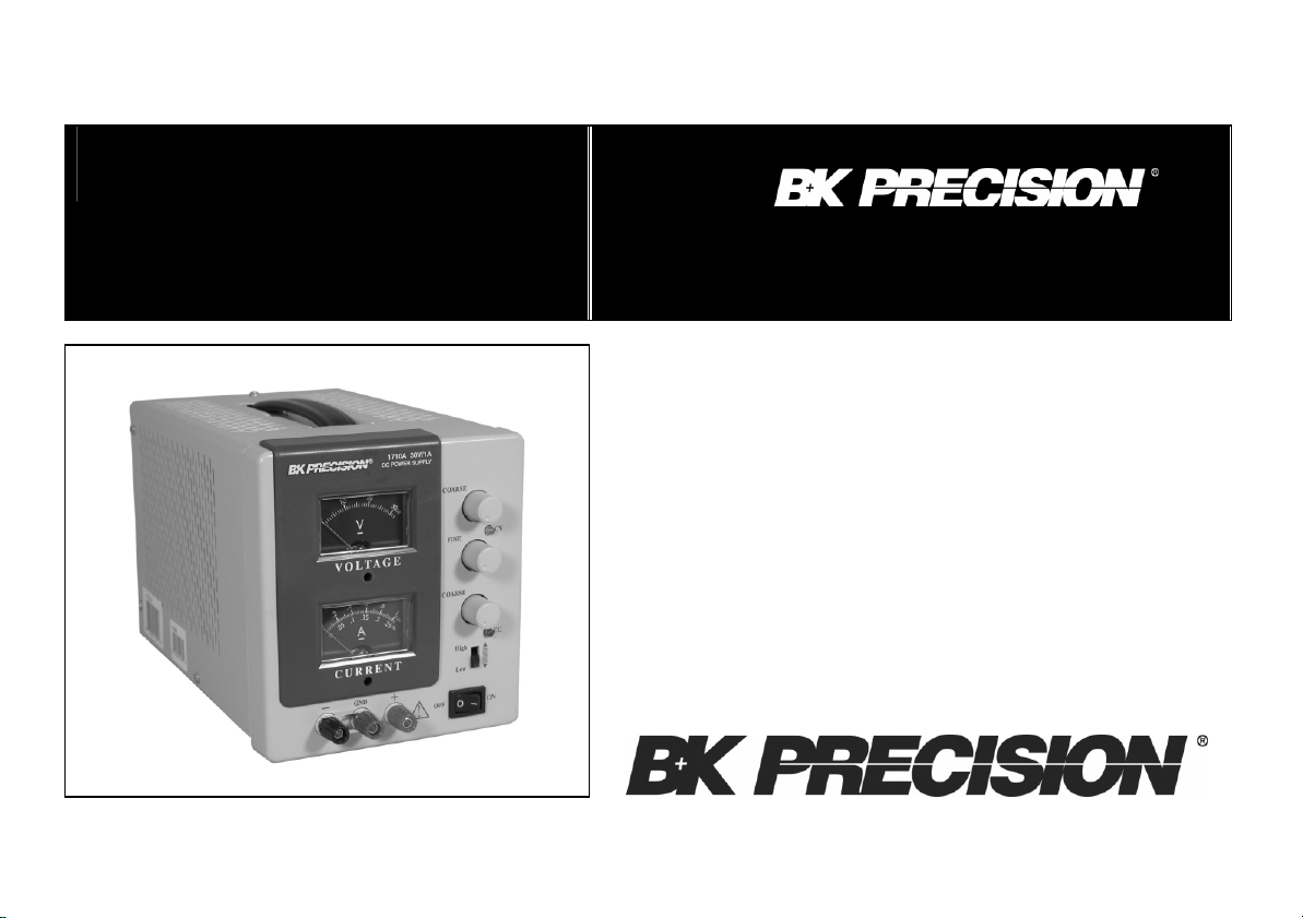
MODELS 1710A and 1730A
INSTRUCTION
MA
NUAL DE
INSTRUCCIÓN
MANUAL
MODELOS 1710A & 1730A
0-30V
DC POWER SUPPLY
0-1A (1710A)
0-3A (1730A)
FUENTE DE PODER DE DC
Page 2

TEST INSTRUMENT SAFETY
Normal use of test equipment exposes you to a certain amount of danger from electrical shock because testing must sometimes be
performed where exposed high voltage is present. An electrical shock causing 10 milliamps of current to pass through the heart will stop
most human heartbeats. Voltage as low as 35 volts dc or ac rms should be considered dangerous and hazardous since it can produce a
lethal current under certain conditions. Higher voltages are even more dangerous. Your normal work habits should include all accepted
practices to prevent contact with exposed high voltage, and to steer current away from your heart in case of ac cidental contact with a
high voltage. Observe the following safety precautions:
1. There is little danger of electrical shock from the dc output of this power supply. However, there are several other possible test
conditions using this power supply that can create a high voltage shock hazard:
a. If the equipment under test is the “hot chassis” type, a serious shock hazard exists unless the equipment is unplugged (just turning
off the equipment does not remove the hazard), or an isolation transformer is used.
b. If the equipment under test is “powered up” (and that equipment uses high voltage in any of its circuits), the power supply outputs
may be floated to the potential at the point of connection. Remember that high voltage may appear at unexpected points in
defective equipment. Do not float the power supply output to more than 100 volts peak with respect to chassis or earth ground.
c. If the equipment under test is “off” (and that equipment uses high voltage in any of its circuits under normal operation), discharge
high-voltage capacitors before making connections or tests. Some circuits retain high voltage long after the equipment is turned
off.
2. Use only a polarized 3-wire ac outlet. This assures that the power supply chassis, case, and ground terminal are connected to a good
earth ground and reduces danger from electrical shock.
3. Don’t expose high voltage needlessly. Remove housings and covers only when necessary. Turn off equipment while making test
connections in high-voltage circuits. Discharge high-voltage capacit ors after removing power.
(continued on inside back cover)
WARNING
1
Page 3

Instruction Manual
for
Model
1710A and 1730A
DC POWER SUPPLY
22820 Savi Ranch Parkway
Yorba Linda, CA 92887
www.bkprecision.com
2
Page 4

TABLE OF CONTENTS
A
PPLICATIONS
................................
.............................
20
TEST INSTRUMENT SAFETY...................inside front cover
INTRODUCTION......................................................................4
FEATURES.................................................................................5
SPECIFICATIONS.....................................................................6
CONTROLS AND INDICATORS............................................8
OPERATING INSTRUCTIONS.............................................10
Safety Precautions................................................................10
Equipment Precautions.........................................................10
Hook-Up................................................................................10
Typical Constant Voltage Operation ...................................13
Setting Current Limit ...........................................................14
Typical Constant Current Operation...................................15
Constant Voltage/Constant Current Characteristic............16
Connecting Two Power Supplies in Series .........................16
Connecting Two Power Supplies in Parallel......................19
General..........................................................................20
Electronics Servicing...................................................20
Electronics Manufacturing..........................................20
Electronics Design Lab...............................................21
Electronics Education..................................................21
Battery Charging..........................................................21
MAINTENANCE.............................................................22
Fuse Replacement ........................................................22
Line Voltage Conversion, Internationa l Units........... 22
1710A/1730A Calibration...........................................23
Instrument Repair Service...........................................23
SERVICE INFORMATION............................................25
LIMITED TWO-YEAR WARRANTY..........................26
SPANISH MANUAL.......................................................28
3
Page 5

INTRODUCTION
The B+K Precision Model 1710A and 1730A DC Power Supplies are high quality, general purpose dc power sources. The two models
are very similar to each other, and both are covered in this instruction manual. Each of these power supplies provides 0-30 volts dc
output, adjustable with both coarse and fine controls for precise settability. The current output of the Model 1710A is 0-1 amp, while
Model 1730A is 0-3 amps. Two current ranges, High and Low, provide excellent current settability and meter resolution. Two large
panel-mounted meters continuously monitor the output voltage and cu rrent.
These power supplies exhibit excellent regulation and low ripple characteristics. The circuit design incorporates a pre-regulator, which
greatly reduces internal power dissipation at low output voltages. The styling is both attractive and functional. The mechanical
configuration conserves bench space and allows for easy portability.
These instrument may be used in constant voltage or constant current applications. The crossover from constant voltage to constant
current modes is smooth and automatic. LEDs indicate the “CV” (constant voltage) or “CC” (constant current) mode of operation. In
constant voltage applications, a current limit may be preset. When load variations cause the current to reach the preset limit, the unit then
regulates output current rather than output voltage. Current limits are adjustable from 5% to 100% of maximum. In constant current
applications, the maxi mum voltage may be preset. When load variations cause current to drop below the regulated value, the unit reverts
to regulated voltage operation at the preset value.
Reverse polarity protection prevents accidental damage to the power supply from improper connection to an external voltage, and
current limiting protects the equipment being powered, as well as the power supply.
The output is isolated from chassis and earth ground, which permits full flexibility of connections. When needed, the (+) or (-) polarity
may be strapped to ground, or either polarity may be floated to an external voltage. Two supplies may be connected in series as a 0 -to-60
volt power source, or two supplies may be connected in parallel, with suitable balancing resistors, for up to twice the output current.
These power supplies are well suited for a wide variety of electrical and electronics applications, including service shops, engineering
labs, production testing, school laboratories, and home use by hobbyists.
4
Page 6

0-30 VOLTS
BUILT
-
IN METERING
controls.
0-1 AMP AND 0-3 AMP VERSIONS
LABORATORY QUALITY
CONSTANT VOLTAGE OR CONSTANT CURRENT
TWO CURRENT RANGES
Continuously variable over 0-to-30 volt range with coarse
and fine controls.
0 to 1 amp (1710A) and 0 to 3 amp (1730A) models
available. Each rated for continuous duty at full output
current.
Excellent regulation, low ripple.
Provides regulated dc voltage output or regulated dc
current output. Crossover is smooth and automatic.
High-Low switch selects full output (0-1A for Model
1710A, 0-3A for Model 1730A), or partial output (0-.25A
for Model 1710A, and 0-.5A for Model 1730A). Low
range improves current stability and meter resolution at
lower current values. Switch simultaneously selects range
of adjustment and corresponding meter scale.
FEATURES
Two large, easy-to-read meters continuously monitor output
voltage and current.
LED INDICATORS
Act as pilot light and identify mode of operation.
PRE-REGULATOR
Limits internal dissipation for higher reliability.
ISOLATED OUTPUT
Either polarity may be floated or grounded.
OVERLOAD PROTECTION
Fully adjustable current limiting (from 5% to 100% of
maximum output current) protects circuit under test and the
power supply.
REVERSE POLARITY PROTECTION
Prevents damage to power supply from external voltage of
reverse polarity.
STYLING
Modern functional styling. Configuration conserves bench
space and aids portability. Logical, convenient layout of
5
Page 7

SPECIFICATIONS
Model 1730A Model 1710A
OUTPUT VOLTAGE 0 to 30 VDC, coarse and fine adjustment 0 to 30 VDC, coarse and fine adjustment
OUTPUT CURRENT
High Range
Low Range
CONSTANT VOLTAGE OPERATION
Voltage Regulation
Line (108 - 132V)
Load (no load to full load)
Recovery Time
Ripple Voltage
Peak-to-Peak
RMS
Temperature Coefficient
0° to +40° C
CONSTANT CURRENT OPERATION
Adjustable Current Limits
Current Regulation
Line (108 - 132V)
Load
Current Ripple
0 to 3A
0 to 0.5A
0.01% + 3mV
0.01% + 3mV
100µs typical
2mV typical
1mV
300 PPM/°C
5 to 100%
0.2% + 3mA
0.2% + 3mA
3mA typical
0 to 1A
0 to 0.25A
0.01% + 3 mV
0.01% + 3 mV
100µs typical
3mV typical
1mV
300 PPM/°C
5 to 100%
0.2% + 3mA
0.2% + 3mA
3mA typical
6
Page 8
Model 1730A Model 1710A
METERING
Voltmeter
Range
Accuracy
Ammeter
High Range
Low Range
Accuracy
POWER REQUIREMENTS Domestic: 120 VAC ±10%, 60 Hz
POWER CONSUMPTION Approx. 180W or less at full load Approx. 70W or less at full load
PROTECTION Reverse polarity protection,
TEMPERATURE RANGE
Operation
Storage
DIMENSIONS (HxWxD) 6.2 x 5.5 x 12.5" 6.2 x 5.5 x 12.5"
WEIGHT 10.5 lb. 8 lb.
ACCESSORIES SUPPLIED Spare Fuse
NOTE: Specifications and information are subject to change without notice. Please visit www.bkprecision.com for the most current product
information.
0 to 32V
±2.5%
0 to 3.2A
0 to 0.53A
±2.5%
International: 120, 220, 230, 240 VAC ±10%, 50/60 Hz
Current limiting
0° to +40° C, <75% R.H.
-15° to +70°C, <85% R.H.
Instruction Manual
0 to 32V
±2.5%
0 to 1.04A
0 to 0.26A
±2.5%
Reverse polarity protection,
Current limiting
0° to +40° C, <75% R.H.
-15° to +70°C, <85% R.H.
Spare Fuse
Instruction Manual
7
Page 9

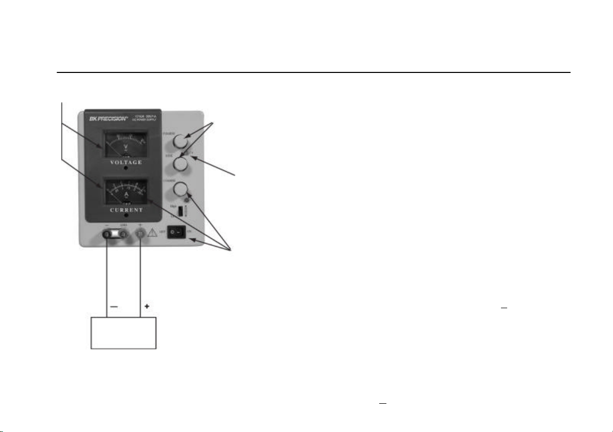
current range: value is read on bottom meter scale of
A
meter.
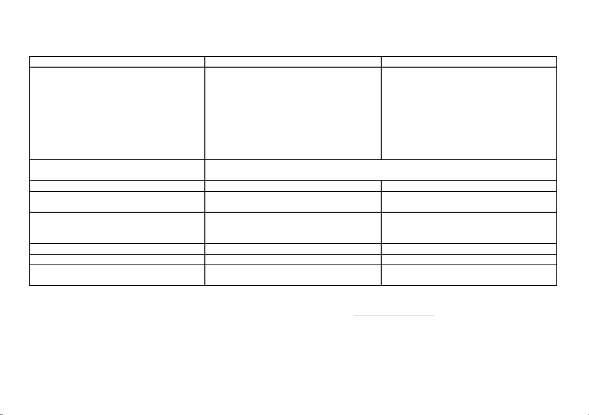
POWER CONTROLS
INDICATORS
Either the “CC” or “CV” indicator will be lighted whenever
the unit is operating, thus serving as a pilot light. The unit
automatically changes from CV to CC operation when the preset
current limit is reached.
1. C.C. (Constant Current) Indicator. Red LED lights in
constant current mode. Unit regulates output current at
value set by CURRENT controls.
2. C.V. (Constant Voltage) Indicator. Green LED lights in
constant voltage mode. Unit regulates output voltage at
value set by VOLTAGE controls.
VOLTAGE CONTROLS
3. Coarse Control. Coarse adjustment of output voltage. Read
value on V meter.
4. Fine Control. Fine adjustment of output voltage. Read
value on V meter.
CURRENT CONTROLS
5. CURRENT Control. Adjusts current limit in constant
voltage mode. Adjusts constant current value in constant
current mode. Range of adjustment is determined by High Low switch.
6. High-Low Switch. High position selects high current range;
value is read on top meter scale of A meter. Low position
selects low
CONTROLS AND INDICATORS
RANGE MODEL 1730A MODEL 1710A
High 0 to 3A 0 to 1A
Low 0 to 0.5A 0 to 0.25A
7. ON-OFF Switch.
OUTPUT TERMINALS
8. “+” Terminal (Red). Positive polarity output terminal.
9. Terminal (Green). Earth and chassis ground.
10. “-” Terminal (Black). Negative polarity output terminal.
METERS
11. A Meter. Reads output current in amperes. Use top scale
when High-Low switch is set to High, bottom scale
when switch is set to Low.
12. V Meter. Reads output voltage on 0 to 32V scale.
REAR PANEL CONTROLS
13. Fuse.
14. Power Cord.
15. 110/220 Line Voltage Conversion Switch.
8
Page 10
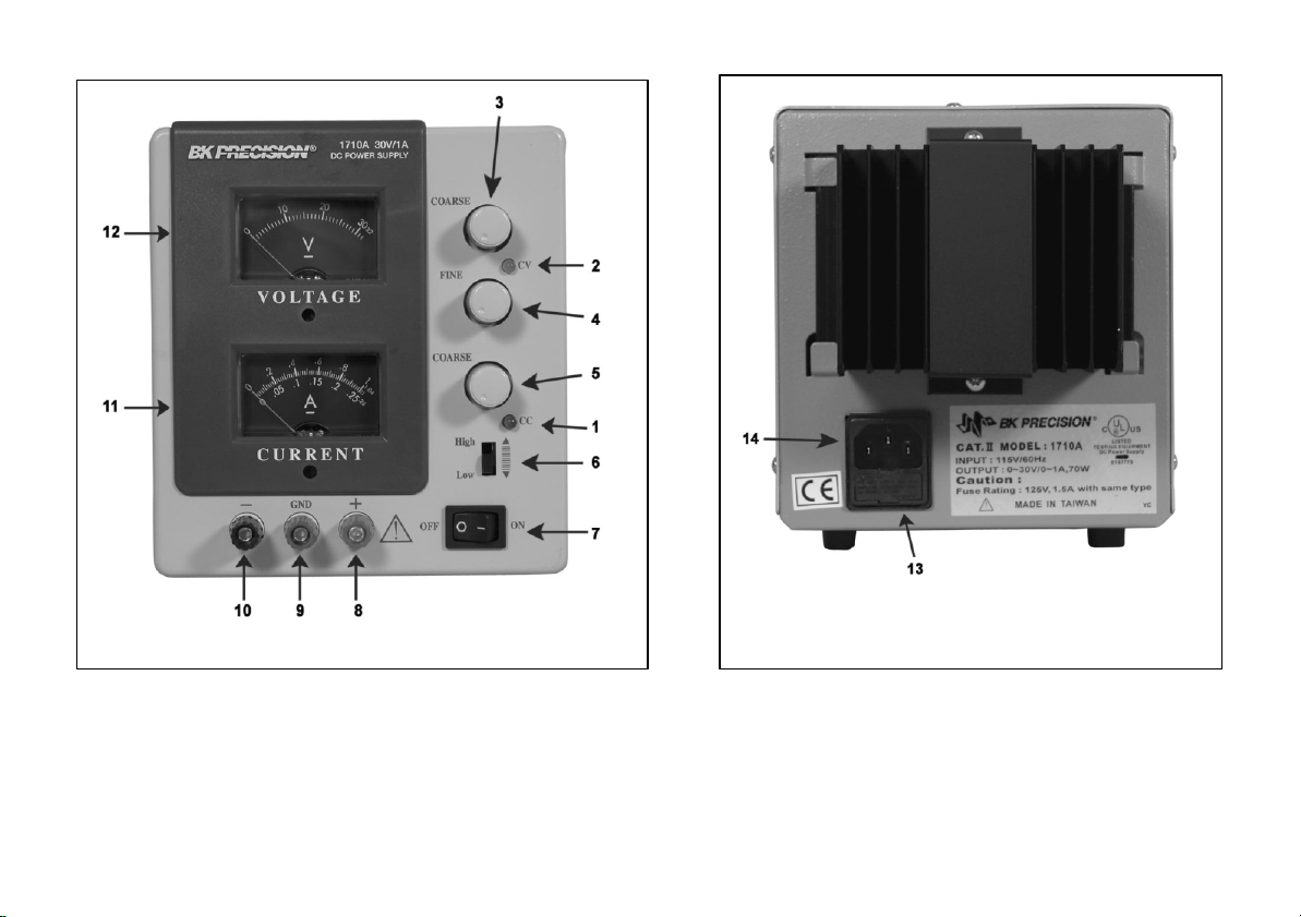
Figure 1. Front Panel Controls and Indicators.
Figure 2. Rear Panel
9
Page 11

OPERATING INSTRUCTIONS
SAFETY PRECAUTIONS
power supply never exceeds
the preset value as the POWER switch is
Use only a polarized 3- wire ac outlet. This assures that the power
supply chassis, case, and ground terminal are connected to a good earth
ground and reduces danger from electrical shock.
There is little danger of electrical shock from the power supply output,
which produces a maximum of 30 volts dc. However, there may be great
danger of electrical shock if the power supply output is connected to
an external high voltage. Some equipment being powered may contain
high voltage and present a shock hazard. Observe caution. If the power
supply out put is floated (referenced to a voltage rather than earth ground)
turn off the power supply and the equipment under test when making
connections. Never float the power supply to a potential greater than 100
volts peak with respect to earth ground.
EQUIPMENT PRECAUTIONS
Avoid using the power supply in ambient temperatures above +40° C.
Always allow sufficient air space around the heat sink at the rear of the
power supply for effective radiation to prevent internal heat build- up.
Although the power supply is protected against reverse polarity
damage, the circuit being powered may not include such protection.
Always carefully observe polarity; incorrect polarity may damage the
equipment under test.
Do not exceed the voltage rating of the circuit being powered. Many
transistors and integrated circuits will not withstand voltage of 30 volts.
There is no need to worry about voltage spikes or overshoot damaging the
equipment under test. The voltage between the output terminals of the
turned on or off.
HOOK-UP
1. Turn off the power supply and the equipment to be powered
during hook- up.
2. Connect the positive polarity of the device being powered to the
red (+) terminal of the power supply.
3. Connect the negative polarity of the device being powered to the
black (-) terminal of the power supply.
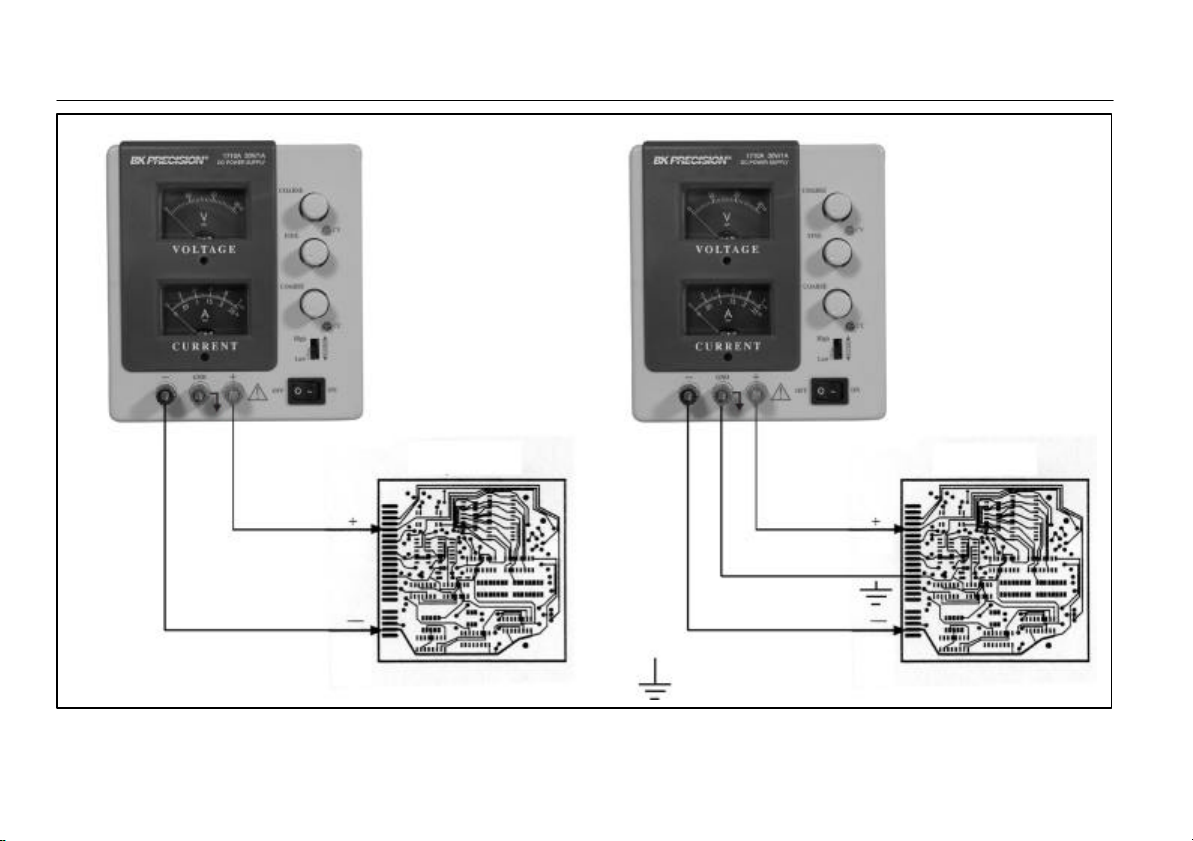
4. Fig. 3 illustrates the grounding possibilities.
a. If the negative polarity of the equipment or circuit being
powered is also the chassis or common, it may be grounded to
earth by strapping the black (-) terminal to the green ( )
terminal as shown in Fig. 3A.
b. Similarly, the positive polarity can be grounded by strapping
the red (+) terminal to the green ( ) terminal as shown in Fig.
3B.
c. If an earth ground reference is not required, the configuration
of Fig. 3C may be used. The scheme in Fig. 3C should also be
used where it is not known whether the chassis is common with
either the positive or negative polarity.
d. If the chassis or common of the equipment being powered is
separate from both the positive and negative polarity power
inputs, use the connection shown in Fig. 3D.
10
Page 12
A. Grounded, common with
Hot
1710A or 1730A
1710A or 1730A
Strap
B. Grounded, common with
OPERATING INSTRUCTIONS
Equipment
Equipment
Strap
negative polarity
POWER SUPPLY
Being Powered
positive polarity
Figure 3 (A and B). Grounding Possibilities.
POWER SUPPLY
Being Powered
Hot
11
Page 13
OPERATING INSTRUCTIONS
No
C. Grounded, common with
1710A or 1730A
1710A or 1730A
No
D. Grounded, not common with
Equipment
Equipment
Strap
negative polarity
POWER SUPPLY
Being Powered
Negative or positive polarity.
Figure 3 (C and D). Grounding Possibilities.
Strap
POWER SUPPLY
Being Powered
12
Page 14
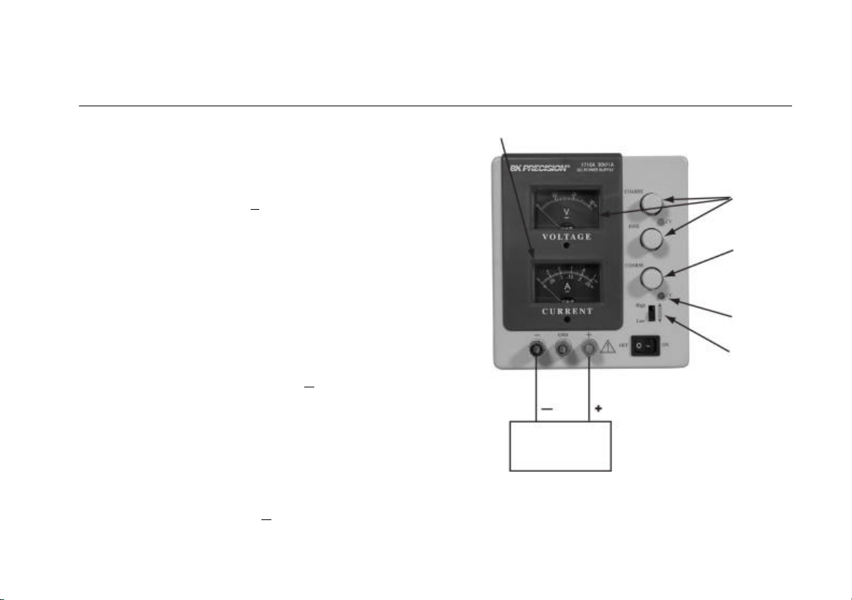
5.
Observe proper polarity. If the circuit being powered is not
OPERATING INSTRUCTIONS
Read output voltage and
Adjust to
CV Indicator on
Current meters
Desired voltage
Load
Figure 4. Typical Constant Voltage Operation
Present current
limiting
equipped with reverse polarity protection, damage to the
circuit can result from reverse polarity. Use color coded
hook-up leads for convenience in identifying polarity, red
for (+) and black for ( -).
6. Make sure that the hook-up leads offer sufficient current
capability and low resistance between the power supply and
the circuits being powered.
TYPICAL CONSTANT VOLTAGE OPERATION
1. Before connecting the device to be powered to the power
supply, determine the maximum safe load current for the
device to be powered and set the current limit value (see
“Setting Current Limit” procedure in this section).
2. Set Fine VOLTAGE control to center and Coarse
VOLTAGE control to minimum (fully counterclockwise).
3. Turn off power supply and connect it to the device to be
powered (see “Hook -Up” procedure in this section).
4. Turn on POWER switch. The CV indicator should light.
5. Increase the VOLTAGE setting until the V meter reads the
desired value. The Fine control permits easier setting to a
specific value.
6. Note the load current on the ammeter.
7. If the load current exceeds the preset current limit, the CV
indicator will go off and the CC indicator will light. In this
case, the power supply automatically switches to the
constant current mode, and further rotation of the
VOLTAGE control will not increase the output voltage as
13
read on the V meter.
Page 15
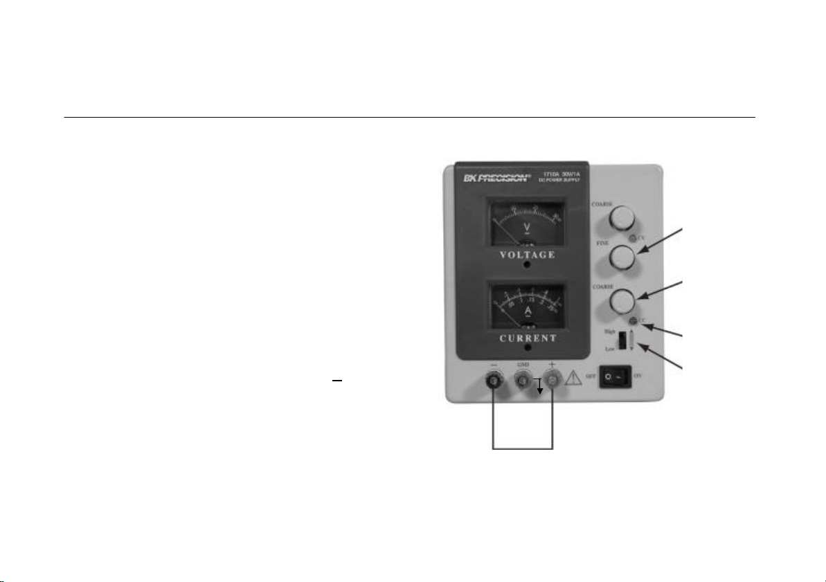
SETTING CURRENT LIMIT
OPERATING INS
TRUCTIONS
Temporarily short
Midrange
1. Determine the maximum safe current for the device
to be powered. If that value is greater than 0.25 A
for Model 1710A, or greater than 0.5 A for Model
1730A, set the High-Low switch to High. If less
than these values, set High-Low switch to Low.
2. Temporarily short the (+) and (-) terminals of the
power supply together with a test lead.
3. Rotate the Coarse VOLTAGE control away from
zero sufficiently for the CC indicator to light.
4. Adjust the CURRENT control for the desired
current limit. Read the current value on the A meter.
5. The current limit (overload protection) has now
been preset. Do not change the CURRENT control
setting after this step.
6. Remove the short between the (+) and (-) terminals
and hook up for constant voltage operation.
Adjust to
desired current
limit
CC Indicator on
Select High
Or Low
range
(+) to (-)
Figure 5. Setting Current Limit.
14
Page 16
TYPICAL CONSTANT CURRENT OPERATION
Read output current
Midrange voltage
OPERATING INSTRUCTIONS
1. Before connecting the device to be powered to the
power supply, determine the maximum safe voltage to
be applied and set the VOLTAGE controls to obtain
that voltage reading on the V meter.
2. Determine the desired constant current value. If greater
than 0.25 A for Model 1710A, or greater than 0.5 A for
Model 1730A, set the High -Low switch to High. If less
than these values, set the High-Low switch to Low.
3. Set the CURRENT control to minimum (fully
counterclockwise).
4. Turn off the power supply and connect it to the device
to be powered.
5. Turn on the power supply. The CC indicator should
light.
6. Increase the CURRENT control setting until the desired
constant current value is read on the A meter, or set the
current limit in advance (before connecting the load) as
prescribed in the earlier “Setting Current Limit”
procedure.
7. If the load current drops below the constant current
value, the CC indicator will go off and the CV indicator
will light. In this case, the power supply automatically
switches to the constant voltage mode, and further
rotation of the CURRENT control will not increase the
output current as read on the A meter.
on meter
limit
Adjust to desired
current
CC Indicator on
Select
High or Low
range
Load
Figure 6. Typical Constant Current Operation.
15
Page 17
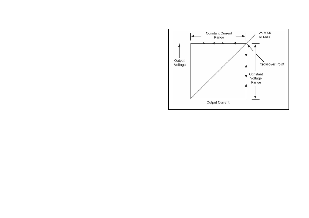
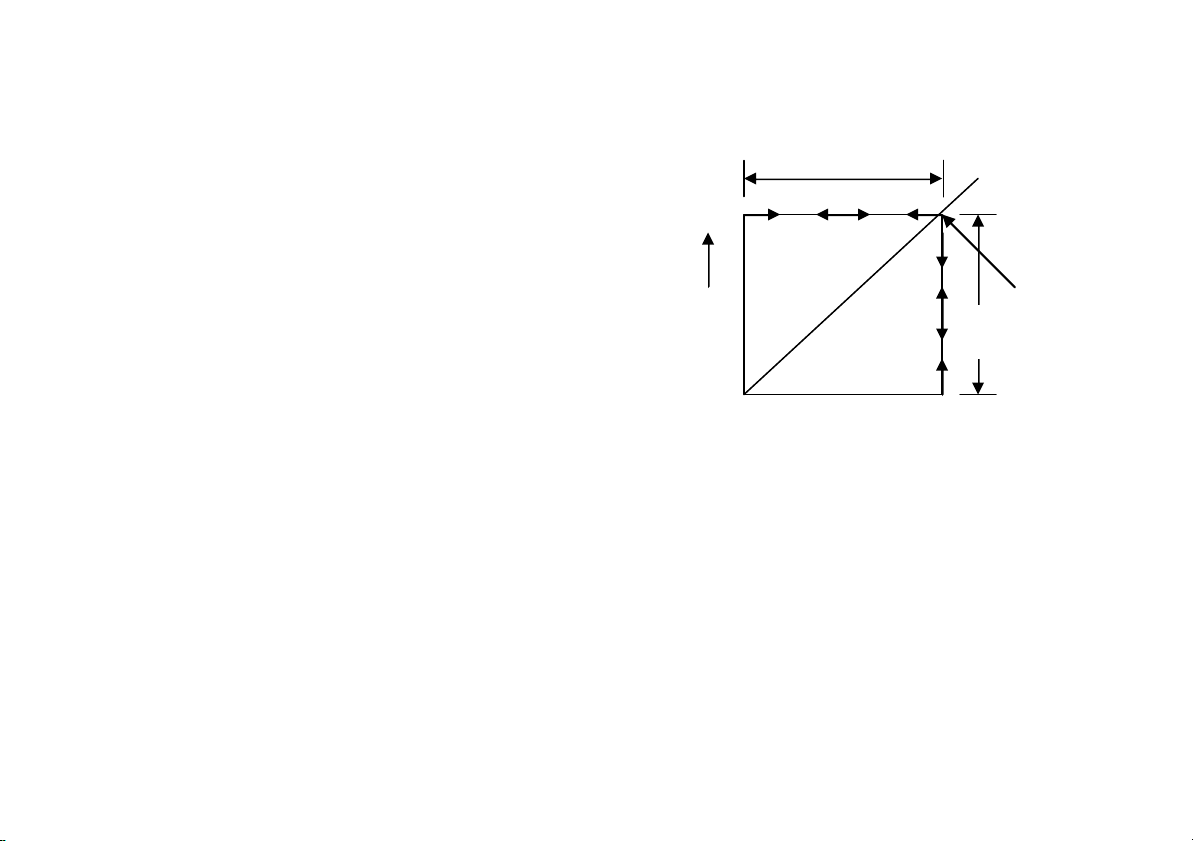
The working characteristic of the Model 1710A and 1730A Power
provide up to 1 amp; two 1730As provide up to 3 amps. See
Supplies is called a constant voltage/constant current automatic crossover
type. This permits continuous transition from constant current to constant
voltage modes in response to the load change. The intersection of constant
voltage and constant current modes is called the crossover point. Fig. 7
shows the relationship between this crossover point and the load.
For example, if the load is such that the power supply is operating in the
constant voltage mode, a regulated output voltage is provided. The output
voltage remains constant as the load increases, up until the point where the
preset current limit is reached. At that point, the output current becomes
constant and the output voltage drops in proportion to further increases in
load. The crossover point is indicated by the front panel LED indicators.
The crossover point is reached when the CV indicator goes off and the CC
indicator comes on.
Similarly, crossover from the constant current to the constant voltage
mode automatically occurs from a decrease in load. A good example of this
would be seen when charging a 12-volt battery. Initially, the open circuit
voltage of the power supply may be preset for 13.8 volts. A low battery will
place a heavy load on the supply and it will operate in the constant current
mode, which may be adjusted for a 1 amp charging rate. As the battery
becomes charged, and its voltage approaches 13.8 volts, its load decreases
to the point where it no longer demands the full 1 amp charging rate. This is
the crossover point where the power supply goes into the constant voltage
mode.
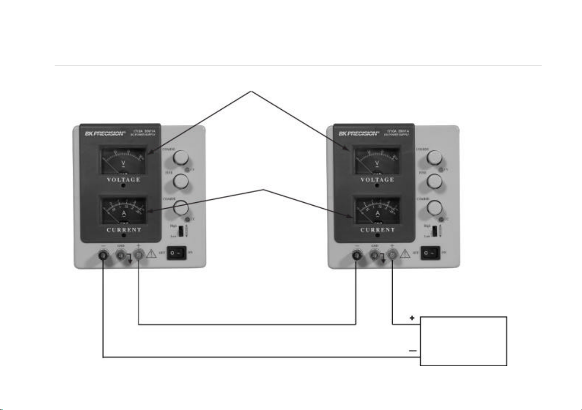
CONNECTING TWO POWER SUPPLIES IN SERIES
Two Model 1710A or 1730A power supplies may be connected in series to
provide a variable 0-60 volt output. In this configuration, two 1710As
16
Figure 7. Constant Voltage/Constant Current Characteristic.
Fig. 8 for the connection scheme.
When connected in series, the VOLTAGE controls of each
power supply exercise control over a 0-30 volt range. Add the
two V meter readings together to determine the total output
voltage, or an external voltmeter may be connected across the
load.
Load current may be monitored from either supply; the
readings will be identical since they are connected in series.
Also, since the supplies are connected in series, it is only
necessary to set the current limit on one of the supplies; the
other may be set for maximum.
Page 18
OPERATING INSTRUCTIONS
Output current
Output voltage equals sum of both voltmeters
equals value on
either ammeter
(both read identic al)
Figure 8. Connecting Two Power Supplies in Series.
Load
17
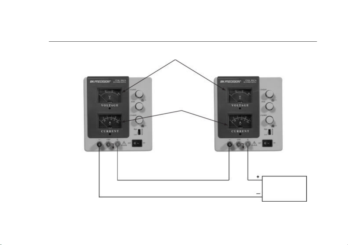
Page 19

OPERATING INSTRUCTIONS
Output current
Power supplies
Use load equalizing
0.1Ω
0.1Ω
equals sum
of both ammeter
1W
1W
Figure 9. Connecting Two Power Supplies in Parallel.
to same voltage
resisters
Load
18
Page 20

CONNECTING
TWO POWER SUPPLIES IN PARALLEL
OPERATING INSTRUCTIONS
Two power supplies may be connected in parallel to double the maximum load current. In this configuration, two 1710As will
provide a variable 0-30 volt output at up to 2 amps; two 1730As will provide a 0-30 volt output at up to 6 amps (heavier gauge
hook-up leads are advisable). Current equalizing resistors must be used as shown in Fig. 9. However, the protective current
limiting feature will prevent damage if current is temporarily unbalanced during set -up.
When connected in parallel and operating in the constant voltage mode, determine the total load current limit and preset the
current limiting for each power supply to half the total load current value. Then when the load is connected, set the VOLTAGE
controls on the two power supplies for equal voltage readings on the V meters. This should also provide approximately equal
current from each supply, as read on the A meters. Add the two A meter readings together for total load current, or connect an
external ammeter in series with the load.
If the current equalizing resistors are not well matched, it is preferable that the voltages be slightly unbalanced to achieve
current balance. Be sure that the supplies are adequately balanced so that both remain in the CV mode.
When connected in parallel and operating in the constant current mode, the VOLTAGE controls of both supplies should be
preset to the same value. Then when the load is connected, the CURRENT controls of the two supplies should be adjusted for
approximately equal current from each unit. Be sure that both supplies remain in the CC mode.
19
Page 21

GENERAL
Some servicing applications require the injection of a
The Model 1710A and 1730A power supplies have a very
wide variety of applications in electrical and electronics
servicing, engineering laboratories, manufacturing and
testing facilities, schools, and home hobbying. The power
supply output is fully adjustable from 0 to 30 volts, and 0 to
1 amp (Model 1710A) or 0 to 3 amps (Model 1730A). This
flexibility makes them suitable for most applications
requiring a dc power source.
ELECTRONICS SERVICING
Most electronics troubleshooting and repair is performed
on a test bench. This power supply can provide the dc power
source to operate a module or circuit board on the test bench
when it is removed from its parent equipment. It can be used
to power portable, battery -operated equipment and check the
effect of low battery voltage. It can power vehicular
equipment such as tape players, auto sound systems, CB
radios, etc. on the test bench.
Most automobiles and other vehicles use 12-volt electrical
systems. Although the electrical system is normally referred
to as a 12 -volt system, actual battery voltage when fully
charged is approximately 14 volts. The power supply may be
set to 14 volts for servicing equipment from v ehicles with
12-volt electrical systems. Some trucks use a 24-volt
electrical system; bench testing of equipment from these
systems should be performed at 28 volts.
APPLICATIONS
variable dc voltage for certain tests, such as checking the
effect of AGC bias in a television receiver. This requires an
isolated dc power supply, such as the Model 1710A or
1730A. The equipment being tested may contain its own
power supply and operate from ac power. A dc voltage may
already be present in the circuit. One polarity of the power
supply output is floated to an appropriate point in the circuit,
such as the emitter of a transistor. The other polarity of the
power supply output is then applied to another point in the
circuit, such as the base of that transistor. Varying the power
supply voltage then varies the dc bias on the stage, and the
effects may be noted. A series limiting resistor is often used
to protect the circuits from overdissipation.
ELECTRONICS MANUFACTURING
In electronics manufacturing facilities, the power supply is
often used as a dc power source while testing and adjusting
modules, subassemblies, and complete units in the production
and assembly area or in the quality control area. The
instrument can be used in incoming inspection as a dc power
source for testing purchased components and subassemblies.
20
Page 22

This power supply is particularly well suited for manufacturing appli
-
can be used in the classroom labo
ratory to conduct experiments in
APPLICATIONS
cations because of its ease of operation and its continuous duty rating.
When load current or total power dissipation are among the main
characteristics to be measured, the total load current and voltage are
instantly displayed on the two meters. The current limit can be set so that
all units which do not meet the load current specification will cause the
CC indicator to light, and the unit can be rejected.
ELECTRONICS DESIGN LAB
The technician or engineer working in an engineering laboratory
requires a dc power supply to power breadboard and prototype circuits.
This power supply is ideal because it monitors both current and voltage
simultaneously, limits current to protect the circuit, is adjustable over a
wide range, and has excellent regulation and very low ripple.
Use of the instrument in an engineering laboratory is very similar to
that described for servicing electronics equipment and modules, except
that lower currents may be prevalent when powering individual circuits.
The current limiting feature is very valuable in this application because it
can protect unproven circuits from damage.
ELECTRONICS EDUCATION
The student in an electronics curriculum may use the power supply for
powering equipment and circuits as previously described for all other
applications. In addition, the power supply
fundamental electronics. In learning Ohm’s law, for example, the
relationships of resistance, current, and
voltage are vividly demonstrated by the use of a power supply.
Being able to observe both the current and voltage meter
simultaneously is a great aid in such experiments.
BATTERY CHARGING
The power supply can be used as a battery charger to restore the
charge in rechargeable batteries such as lead-acid, nickel-cadmium,
and some alkaline types. Refer to the battery manufacturer’s
charging specifications for proper voltage and current settings.
Charging information is sometimes printed on the batteries. Battery
charging, at least initially, requires the constant current mode of
operation. Before connecting the power sup ply to the battery, preset
the VOLTAGE controls to the fully charged terminal voltage
specified by the battery manufacturer. Turn off the power supply
while connecting the battery. Observe proper polarity and connect as
for constant current operation. Adjust the CURRENT control for the
maximum charging current specified by the battery manufacturer (If
the maximum charging current is greater than the power supply’s
maximum load current, set the CURRENT control to maximum). The
CC indicator will light and the battery will charge at the preset
current limit, which can be read on the A meter. As the battery
approaches full charge, its terminal voltage will approach that of the
power supply output and the charging current will taper off. The
power supply may automatically switch to CV (constant voltage)
operation. When this occurs, the power supply will continue to
provide a trickle charge.
21
Page 23

WARNING
LINE VOLTAGE CONVERSION, INTERNATIONAL UNITS
The following instructions are for use by qualified personnel only. To
avoid electrical shock, do not perform any servicing other than
contained in the operating instructions unless you are qualified to do
so.
FUSE REPLACEMENT
If the fuse blows, the CV, CC, or LED meter indicators will not
light and the power supply will not operate. The fuse should not
normally open unless a problem has developed in the unit. Try to
determine and correct the cause of the blown fuse, then replace only
with a fuse of the correct rating.
MODEL OPERATION FUSE VALUE
1710A
1730A
Table 1. Fuse Values.
120V
220 / 230 / 240V
120V
220 / 230 / 240V
1.5 A, 250V
1 A, 250V
2.5 A, 250V
1.5A, 250V
MAINTENANCE
This power supply can be switched from 110 VAC to
220/230/240 VAC by a switch located on the rear panel. To
select the desired line voltage, simply insert the fuse and fuse
holder so that the appropriate voltage is pointed to by the arrow.
Be sure to use the proper vale fuse (see label on rear panel).
22
Page 24

1710A/1730A CALIBRATION
6.
Set the front panel Coarse
VOLTAGE
control for a reading of
MAINTENANCE
If readjustment is required, use the following procedure.
Locations of the adjustments are shown in Fig. 11. The meters
may be mechanically zeroed through their front panel access
holes prior to any calibration.
1. Set the front panel controls as follows:
Coarse and Fine VOLTAGE controls fully clockwise.
CURRENT control fully clockwise.
High-Low switch to Low .
Power switch to On.
2. Connect the multimeter to measure the voltage at pin 7 of
IC2 with respect to the front panel red (+) output jack.
Adjust R21 for -5.00 volts on the multimeter.
3. Connect the multimeter to measure the voltage at pin 1 of
IC2 with respect to the front panel red (+) output jack.
Adjust R63 for 0 ±10 mV on the multimeter.
4. Connect the multimeter to measure the DC voltage
between the black (-) and red (+) output jacks. The
voltage should be 30 to 32 volts, the green CV indicator
should be lit, and the red CC indicator should be off.
5. Set the front panel Fine VOLTAGE control for a reading
of 30.0 volts on the multimeter. Adjust upper R54 for a
front panel meter reading of 30.0 volts on the
VOLTAGE meter.
10 volts on the VOLTAGE meter.
7. Set High-Low switch to High.
8. Connect the multimeter to read the DC current between the
black (-) and red (+) output jacks, using the 10 amp range. The
red CC indicator should light and the green CV indicator
should go off.
9. Set the front panel CURRENT control for a reading of 1.00
amps on the multimeter for the Model 1710A, or 3.00 amps
for the Model 1730A. Adjust R56 for a front panel meter
reading the same as the multimeter.
10. Set the High-Low switch to Low, the multimeter should read
0.25 ± 2 counts for the Model 1710A, or 0.50 ± 2 counts for
the Model 1730A.
INSTRUMENT REPAIR SERVICE
Because of the specialized skills and test equipment required for
instrument repair and calibration, many customers prefer to rely
upon B+K Precision for this service. We maintain a network of
B+K Precision authorized service agencies for this purpose. To use
this service, even if the instrument is no longer under warranty,
follow the instructions given in the WARRANTY SERVICE
INSTRUCTIONS section of this manual. There is a nominal charge
for instruments out of warranty.
23
Page 25

Figure 11. Location of Adjustments.
24
Page 26

SERVICE INFORMATION
Warranty Service: Please return the product in the original packaging with proof of purchase to the address below.
Clearly state in writing the performance problem and return any leads, probes, connectors and accessories that you
are using with the device.
Non-Warranty Service: Return the product in the original packaging to the address below. Clearly state in writing the
performance problem and return any leads, probes, connectors and accessories that you are using with the device.
Customers not on open account must include payment in the form of a money order or credit card. For the most
current repair charges please visit www.bkprecision.com and click on “service/repair”.
Return all merchandise to B&K Precision Corp. with pre-paid shipping. The flat -rate repair charge for Non-Warranty
Service does not include return shipping. Return shipping to locations in North American is included for Warranty
Service. For overnight shipments and non-North American shipping fees please contact B&K Precision Corp.
B&K Precision Corp.
22820 Savi Ranch Parkway
Yorba Linda, CA 92887
www.bkprecision.com
714-921-9095
Include with the returned instrument your complete return shipping address, contact name, phone number
and description of problem.
25
Page 27

Limited Two-Year Warranty
B&K Precision Corp. warrants to the original purchaser that its products and the component parts thereof, will be free
from defects in workmanship and materials for a period of two years from date of purchase.
B&K Precision Corp. will, without charge, repair or replace, at its option, defective product or component parts.
Returned product must be accompanied by proof of the purchase date in the form of a sales receipt.
To obtain warranty coverage in the U.S.A., this product must be registered by completing a warranty registration form
online at www.bkprecision.com within fifteen (15) days of purchase.
Exclusions: This warranty does not apply in the event of misuse or abuse of the product or as a result of
unauthorized alterations or repairs. The warranty is void if the serial number is altered, defaced or removed.
B&K Precision Corp. shall not be liable for any consequential damages, including without limitation damages resulting
from loss of use. Some states do not allow limitations of incidental or consequential damages. So the above limitation
or exclusion may not apply to you.
This warranty gives you specific rights and you may have other rights, which vary from state-to-state.
B&K Precision Corp.
22820 Savi Ranch Parkway
Yorba Linda, CA 92887
www.bkprecision.com
714-921-9095
Model Number: ___________________ Date Purchased: ____________________
26
Page 28

TEST INSTRUMENT SAFETY
4. If possible, familiarize yourself with the equipment being tested and the location of its high voltage points. However, remember that
high voltage may appear at unexpected points in defective equipment.
5. Use an insulated floor material or a large, insulated floor mat to stand on, and an insulated work surface on which to place
equipment; and make certain such surfaces are not damp or wet.
6. When testing ac powered equipment, the ac line voltage is usually present on some power input circuits such as the on-off switch,
fuses, power transformer, etc. “any time” the equipment is connected to an ac outlet.
7. B+K Precision products are not authorized for use in any application involving direct contact between our product and the human
body, or for use as a critical component in a life support device or system. Here, “direct contact” refers to any connection from or to
our equipment via any cabling or switching means. A “critical component” is any component of a life support device or system
whose failure to perform can be reasonably expected to cause failure of that device or system, or to affect its safety or effectiveness.
8. Never work alone. Someone should be nearby to render aid if necessary. Training in CPR (cardio-pulmonary resuscitation) first aid
is highly recommended.
(continued from inside fro nt cover)
27
Page 29

Uso normal de probado de prueba te espose a cierta cantidad de peligro por un choque eléctrico porque revisiones son algunas veces hechas
donde hay alto voltaje descubierto. Un choque eléctrico que cause 10 milliamps pasar a través del corazón pararía la mayoría de los
corazones humanos. Voltaje tan bajo hasta 30 voltios dc ou ac rms podría ser considerado peligroso porque puede producir una corriente letal
bajo ciertas condiciones. Voltajes mas alt os pueden ser aun mas peligrosos. Tus hábitos normales de trabajo deben de incluir todas las
practicas aceptadas para prevenir contacto con alto voltaje descubierto, y dirigir corriente lejos de el corazón en caso de contacto accidental
con un alto voltaje. Observe las siguientes medidas de seguridad:
1. Hay poco peligro de un choque eléctrico de la salida de cd de esta fuente de poder. Pero, puede haber otras posibles condiciones de
prueba que cuando usando esta fuente de poder se puede crear un peligro de un choque de alto voltaje.
• Si el equipo bajo prueba es de el tipo “chasis caliente”, un serio peligro de choque existe al menos que el equipo este desconectado
( nada mas apagando el equipo no remueve el peligro), o si un transformador de aislamiento es usado.
• Si el equipo bajo prueba esta “prendido” (y este equipo usa alto voltaje en cualquiera de sus circuitos), las salidas de la fuente de
poder pueden ser flotadas a el potencial al el punto de conexión. Recuerden que el alto poder puede aparecer en puntos inesperados
en equipo defectuoso. No flote la salida de la fuente de poder por mas de 100 voltios pico con respecto al chasis o tierra.
• Si el equipo bajo prueba esta “apagado” (y este equipo usa alto voltaje en cualquiera de sus circuitos cuando en operación normal),
descarga alto-voltaje capacitares antes de hacer conexiones o pruebas. Algunos circuitos conservan alto voltaje mucho después que
el equipo es apagado.
2. Solo use una enchufe polarizada de 3-conductores. Esto asegura que el chasis de la fuente de poder, cubierta, y la terminal de tierra están
conectadas a una buena tierra y reduce el peligro de un choque eléctrico.
3. No se expone a alto poder innecesariamente. Remueva cubiertas solo cuando mas necesario. Apague el equipo cuando este haciendo
conexiones de prueba en circuito de alto-voltaje. Descargue los capacitadotes después de que remueva el poder.
(continua el la parte de atrás)
SEGURIDAD DE EL INSTRUMENTO DE PRUEBA
PRECAUCIONES
28
Page 30

SEGURIDAD DE EQUIPO DE PRUEBA
APLICACIONES
--------------------------------
-------------
46
TABLA DE CONTENIDO
INTRODUCTION .................................................................30
CARACTERISTICAS...........................................................31
ESPECIFICACIONES...........................................................32
CONTROLES & INDICADORES........................................34
INTRODUCIONES DE OPERACIÓN.................................36
precauciones de segundad......................................................36
precauciones del equipo.........................................................36
Típica operación de voltaje constante...................................39
Estableciendo el limite de corriente .......................................40
Típica operación de corriente constante.................................41
Voltaje constante / corriente constante Características.........42
Conectando dos fuentes de poder en serie.............................42
Conectando dos fuentes de poder en paralelo........................45
General ---------------------------------------------------------46
servicio electrónico -------------------------------------------46
electrónica en manufactura ----------------------------------46
laboratorio de diseño electrónico ---------------------------47
educación en electrónica-------------------------------------47
cargado de baterias/pilas -------------------------------------47
MANTENIMIENTO-----------------------------------------48
Remplazo de fusibles -----------------------------------------48
conversión de línea de voltaje ------------------------------48
Ajustamiento---------------------------------------------------48
Calibración ---------------------------------------------------49
Informaction De Servic o----------------------------------51
29
Page 31

El B & K Precision Modelo 1710A y 1730A CD Fuente de
regula la corriente d
e salida en vez de el voltaje de salida.
INTRODUCCION
Poder es de una alta calidad, propósito general cd fuente de
poder. Provee 0 –30 voltios cd salida, ajustable con ambos
grueso y fino controles de voltaje para precisos ajustes. El
Modelo 1710A es de 0-1 amps, mientras que el 1730A es de 0-3
amps. Dos intervalos de corriente, alta y baja, facilitan una
excelente estabilidad de corriente y contador de resolución.
Dos medidores grandes, montados en el panel frontal,
continuamente controlan la salida del voltaje y corriente.
Estas fuente de poder 1710A y 1730A exhibe excelente
regulación y baja ondulación características. El diseño de el
circuito incorpora un pre-regulador , cual grandemente reduce
disipación de poder interna a bajos voltajes de salida. El estilo es
ambo atractivo y funcional. La configuración mecánica conserva
espacio y permite fácil portabilidad.
Estos instrumentos puede ser usado en constante voltaje o
constante corriente aplicaciones. El cambio de constante voltaje
a constante corriente modo es suave y automático. LED’s
indican el “VC” (voltaje constante) o CC( constante corriente)
modo de operación. En aplicaciones de voltaje constante, un
limite de corriente esta presente. Cuando variaciones de carga
causan la corriente alcanzar el limite presente, la unidad entonces
Limites de corriente son ajustables desde 5% hasta 100%
máximo. En aplicaciones de constante corriente, el voltaje
máximo puede estar presente. Cuando variaciones de carga
causan una baja de corriente por debajo de el valor regulado,
la unidad cambia a operación de voltaje regulado a el
prerregulado valor.
Polaridad reversa protección previene daño accidental a la
fuente de poder de conexiones inapropiadas a un voltaje
externo, y la corriente de limitación protege el equipo que
esta siendo prendido, como también a la fuente de poder.
La salida esta aislada de el chasis y tierra, cual permite total
flexibilidad de conexiones. Cuando necesitado, el (+) o (-)
polaridad puede estar atados a tierra, o la polaridad puede
estar flotando a un voltaje externo. Dos fuentes pueden
estar conectadas en series como a 0-60 voltios fuente de
poder, o dos fuentes pueden ser conectadas en paralelo, con
adecuados resistores balanceadores, por hasta doble la
corriente de salida.
Esta fuente de poder esta muy adecuada para una amplia
variedad de aplicaciones eléctricas y electrónicas,
incluyendo talleres de servicio, laboratorios de ingeniería,
pruebas de producción, laboratorios de escuela, y uso de
casa por aficionados
30
Page 32

0-30 VOTIO
S
INDICADOR INTEGRADO
Continuamente variable sobre 0 a 30 voltios rango con
grueso y fino controles
Versiones 0-1 AMP y 0-3 AMP
Los modelos 0-a-1 amp (1710A) y 0-a-3 amp (1730A) son
disponibles. Cada cual clasificado por su continuo
rendimiento su máxima salida de corriente.
CALIDAD DE LABORATORIO
Excelente regulacio,baja onduracio
VOLTAJE CONSTANTE O CORRIETE CONSTANTE
Provees regulado cd voltaje de salida o salida regulada de
corriente cd .Cruce es suave
Y automático
DOS MARGENES DE CORRIENTE
Interruptor Alto-Bajo selecciona máxima salida (0-1A para
el Modelo 1710A, 0-3A para el Modelo 1730A), o salida
parcial (0-.25A para el Modelo 1710A, y 0-.5A para el
Modelo 1730A). El intervalo bajo mera la estabilidad de la
corriente y del contador de resolución en los valores de la
corriente baja. El interruptor selecciona simultáneamente el
margen de ajuste y el grado de escale correspondiente.
CARACTERÍSTICAS
Dos medidores grandes y fáciles de leer, continuamente
supervisan la salida del voltaje y corriente.
LED INDICADOVES
Actúa como piloto y identifica el modo de operación y
medida
PRE-REGULADOR
Limita disipación interna para mas alta confiabilidad
SALIDA AISLADA
La polaridad puede ser flotadon o a tierra
PROTECCIÓN DE SOBRECARGA
Completamente ajuste de limitación de corriente(desde
5% a 100% de máximo
Salida de corriente )protege circuitos bajo prueba y la
fuente de poder
PROTECCIÓN DE POLARIDAD VOLTEADA
Previene daño ala fuente de energía de volltaje externos
de polaridad volteada
ESTILO
Estilo de funcionalidad moderna.Configuración conuerva
31
espacio de banca y ayuda a
Si poryabilidad.Lógico,converniente layout de controles
Page 33

ESPECIFICACIONES
VOLTAJE DE SALIDA 0 a 30VDC grueso y fino ajuste 0 a 30VDC grueso y fino ajuste
CORRIENTE DE SALIDA
Intervalo alto
Intervalo bajo
OPERACIÓN DE CONSTANTE VOLTAJE
Regulación de voltaje
Linea (108-132V)
Carga(no carga a carga completa)
Tiampo de reoperación
Voltaje deondulación
Pico a pico
RMS
Coeficiente de temperatura
( 0 a +35 C )
OPARACION DE CONSTATE
Limites ajustables de corriente
Regulación de corriente
Linea (108-132V)
Carga
Corriente de ondulación
Modelo 1730A Modelo 1710A
0 a 3A
0 a .5A
0.01% + 3mv
0.01% + 3mv
100 us típico
2mv típico
1mv
300PPm/o °C
5% a100%
0.2% + 3mA
0.2% + 3mA
3mA típico
0 a 1A
0 a .25A
0.01% + 3mv
0.01% + 3mv
100us típico
3mV típico
1mv
5% a100%
0.2% + 3mA
0.2% + 3mA
3mA típico
32
Page 34

MIDIEDO
Volmetro
Rango
Precision
Ametro
Margen alto
Margen bajo
Precision
REQUERIMIENTE DE PODER
Domestico
Internacional
CONSUMO DE PODER Aproximadamente 180W o menos a
PROTECCIÓN Protección de polaridad
RANGO DE TEMPERATURA
Operación
Almacenamiento
DIMENSIONES(AxAxP) 6.2 x 5.5 x 12.5” 6.2 x 5.5 x 12.5”
PESO 8 LB 10.5 LB
ACCESORIOS INCLUIDOS Fusible extra,Manual de
NOTA: Las especificaciones y la información están conforme a cambio sin el aviso de B&K Precision Corp. Por
favor visite www.bkprecision.com para las especificaciones más corriente y información de nuestros productos.
Modelo 1730A Modelo 1710A
0 a 32V
+/-2.5%
0 a 3.2A
0 a 0.53 A
+/-2.5%
120VAC +/- 10%,60Hz
120/220/230/240VAC+/10%,50/60Hz
carga completa
volteada,limitación de corriente
0° a +40°C, 75%R.H
-15° a +70°C, 85% R,H
instrucciones
0 a 32V
+/-2.5%
0 a 1.04 A
0 a 0.26 A
+/-2.5%
120VAC +/- 10%,60Hz
120/220/230/240VAC+/10%,50/60Hz
Aproximadamente 70W o menos
a carga Completa
Protección de polaridad
volteada,limitación de corriente
0° a +40°C, 75%R.H
-15° a +70°C, 85% R,H
Fusible extra,Manual de
instrucciones
33
Page 35

CONTROLES Y INDICADORES
INDICADORES
Sea el “CC” o “CV” y los LED indicadores pueden ser
prendidos cuando sea que la unidad este operando, de este
Rango 1730A 1710A
Alto 0 a 3A 0 a 1A
Bajo 0 a .5A 0 a .25A
modo sirviendo como una luz piloto. La unidad
automáticamente cambia de CV a CC operación cuando el
preseleccionado limite de corriente es alcanzado.
1. C.C. (corriente constante) Indicador. Roja LED
prende en constante corriente modo. La unidad
regula la corriente de salida at un valor establecido
por los CURRENT (corriente )controles.
2. C.V. (voltaje constante) indicador. Verde LED
prende en constante voltaje modo. La unidad regula
el voltaje de salida establecido por los
VOLTAGE(voltaje) controles.
CONTROLES DE VOLTAJE
3. Grueso Control (Control grueso) . Ajustes gruesos
de el voltaje de salida. Leer valor en el voltímetro
4. Fine Control (control fino). Ajuste fino de salida de
voltaje. Leer valor en el voltímetro.
CONTROLES DE CORRIENTE
5. Grueso CURRENT(corriente) control. Ajuste el
limite de corriente en constante voltaje modo.
Ajusta constante valor de corriente en el constante
corriente modo. Un margen de ajuste es
determinado por un interruptor de Alto y bajo.
6. Interruptor Alto-Bajo. Posición alta selecciona un
margen de corriente alta; el valor es leído en la parte
superior del medidor de escala del Amperímetro.
Posición baja selecciona un margen de corriente
baja; el valor es leído en lar parte inferior del
medidor de escala de Amperímetro
CONTROLES DE PODER
7. prendido-apagado switch.
TERMINALES DE SALIDA
8. “+” Terminal (rojo). Positiva polaridad terminal
de salida.
9. GND Terminal. Tierra y chasis tierra.
10. “ -“ Terminal (negra). Negativa polaridad
terminal de salida.
11. Amperímetro. Lee la salida de corriente en
amperes. Use al escala superior cuando el
interruptor Alto -Bajo es ajustado a alto, escala
inferior cuando el interruptor está ajustado a
Bajo
12. Voltímetro. Lee la salida de voltaje en escala de
0 hasta 32 V.
CONTROLES DEL PANEL TRASERO
13. Fusible
14. Cordón de poder
15. .Switch de conversión de line
34
Page 36

indicadores de el panel delantero Figura 2.Panel trasero
Figura 1.Controles y
35
Page 37

INSTRUCCIONES DE OPERACIÓN
PRECAUCIONES DE SEGURIDAD
Use solo a polarizado 3-conductores ca enchufe. Esto asegure
que la fuente de poder chasis, caja, y la terminal de tierra son
conectada a una buena tierra y reduce el peligro de un choque
eléctrico.
Hay un pequeño peligro de choque eléctrico dela salida de la
fuente de poder, cual produce un máximo de 30 voltios cd. Pero,
puede haber un gran peligro de choque eléctrico si la salida de la
fuente de poder es conectada a un extremado alto voltaje. Algún
equipo siendo prendido puede contener alto voltaje y presenta un
peligro de choque. Observe precaución. Si la salida de la fuente
de poder es flotada (referencia a un voltaje en vez que la tierra)
apague la fuente de poder y el equipo bajo prueba cuando este
haciendo conexiones. Nunca flote la fuente de poder a un
potencial mas grande que 100 voltios pico con respecto a la tierra.
PRECAUCIONES DEL EQUIPO
Evite usar la fuente de poder en temperaturas ambientales arriba
de +40 C. Siempre permita suficiente espacio de aire alrededor de
el disipador de calor en al parte trasera de la fuente de poder para
una radiación efectiva para prevenir calor interno atrapado.
Aunque la fuente de poder esta protegida enconara de daño de
polaridad volteada, el circuito que esta prendido no puede incluir
tal protección. Siempre cuidadosamente
observe la polaridad; polaridad incorrecta puede dañar el equipo
bajo prueba.
No exceda los voltajes recomendados de los circuitos que son
prendidos. Muchos transistores y circuitos integrados no pueden
tolerar voltajes de 30 voltios.
No hay necesidad de preocuparse acerca de brincos de voltaje o
sobresaltos dañando el equipo bajo prueba. El entre las terminales de
salida de la fuente de poder nunca excede el establecido valor cuando
el (Power) switch de poder es apagado o encendido.
Conexión
1. Apague la fuente de poder y el equipo que va ha ser prendido
cuando este conectando.
2. Conecte la polaridad positiva a el dispositivo que va a ser
prendido a la terminal roja de la fuente de poder.
3. Conecte la polaridad negativa de el dispositivo que va a ser
prendido a la terminal negra de la fuente de poder.
4. Fig. 3 ilustra las posibilidades de tierra.
a. Si la polaridad negativa de el equipo o el circuito que esta
encendido es también el chasis o común, puede ser
conectado a tierra por medio de atando la terminal negra a la
verde como en Fig.3A
b. Similarmente, la polaridad positiva puede ser conectada a
tierra atando la terminal roja a la verde como es mostrado
en la Fig.3
c Si la referencia de tierra no es requerida, la configuración de Fig.
3C puede ser usada. El diagrama in Fig.3C debería también ser
usado donde no es conocido si el chasis es común con la
polaridad positiva o negativa.
d Si el chasis o común de el equipo encendido es separado de ambas
polaridades negativa y positiva entradas de poder, use la conexión en
Fig. 3D
36
Page 38

A. Tierra, comun co
n
B. Tierra, comun con
INSTRUCCIONES DE OPERACIÓN
Corto
Polaridad negativas
Corto
Equipo encendido Equipo encendido
Caliente
Caliente
polaridad positiva
Figura 3 A y B .Posibilidades de conecciones etierra
37
Page 39

D.
Negativas o P
ositivas
Sin
Sin
INSTRUCCIONES DE OPERACIÓN
C. No referencia a tierra
Corto
Equipo encendido
Figura 3 C y D .Posibilidades de conecciones etierra
Corto
Equipo encendido
A tierra,no comu n con polaridades
38
Page 40

Lectura de voltaje de salida en
Ajust al voltaje
CV indicador
Preestablecido
INSTRUCCIONES DE OPERACIÓN
OPERACION TIPICA DE VOLTAJE CONSTANTE
1. Antes de conectar el dispositivo para ser encendido por la
fuente de poder, determine la máxima carga de corriente
segura para el dispositivo que va ha ser encendido y
establezca el valor de el limite de corriente (vea
“Establecer el limite de corriente” procedimiento en esta
sección)
2. Coloque el control de VOLT AJE fino en el centro y el
control de VOLTAJE grueso al mínimo (completamente en
la dirección en contra de las anejillas de reloj)
3. Apague la fuente de poder y conéctela a el dispositivo que
va ha ser prendido. (vea “Conectado” procedimiento en
esta sección ).
4. Prenda el POWER switch. The CV luz de el indicador
debe de prender.
5. xAumente la posición de el VOLTAJE hasta que la Voltaje
El voltímetro lee el valor deseado. El control FINO
permite mas fácil colocación a un valor especifico.
6. Note la carga de la corriente En el amperímetro.
7. Si la carga de corriente excede el limite de corriente
establecido, el CV indicador se apagara y el indicador de
CC prendera. En este caso , la fuente de poder
automáticamente cambiara a el modo de constante
corriente, y ma s rotación de el control de VOLTAJE
aumentara la salida de voltaje Como es leído en el
voltímetro
Medidores de voltaje y corriente
Deseado
Prendido
Limite de corriente
Carga
Figura 4. Típica operación de voltaje constante
39
Page 41

Ajuste al
límite
Seleccione margen
Corto circuito temporal
CC indicador
INSTRUCCIONES DE OPERACIÓN
8. xAumente la posición de el VOLTAJE hasta que la Voltaje
El voltímetro lee el valor deseado. El control FINO permite
mas fácil colocación a un valor especifico.
9. Note la carga de la corriente En el amperímetro.
10. Si la carga de corriente excede el limite de corriente
establecido, el CV indicador se apagara y el indicador de
CC prendera. En este caso , la fuente de poder
automáticamente cambiara a el modo de constante corriente,
y mas rotación de el control de VOLTAJE aumentara la
salida de voltaje Como es leído en el voltímetro
ESTABLECIENDO EL LIMITE DE CORRIENTE
1. Determine la máxima corriente permitida para el dispositivo
que va ha ser encendido. Si el valor es mayor que 0.25 A
para el modelo 1710A, o mayor que 0.5 A para el modelo
1730A, fije el interruptor Alto-Baja a Alto. Si es menor que
estos valores, fije el interruptor Alto -Bajo a Bajo
2. Temporalmente toque la (+) y (-) terminales de la fuente de
poder con una sonda de prueba.
3. Rote el control de Voltaje grueso lejos de el cero
suficientemente para encender el indicador de CC .
4. Ajuste el grueso y fino CORRIENTE control para el deseado
limite de corriente. Lea el va lor de la corriente en el
amperímetro.
5. El limite de corriente (sobrecarga protección) ha sido
establecido. No - camble la posición de los controles de
CORRIENTE después de este paso.
6. Remueva el corto cicuito entre la (+) y (-) terminales y
conecte para la operación de constante voltaje
Figura 5. Estableciendo el limite de corriente
(+) to (-)
40
Rango medio
de corriente deseado
Prendido
Alto o Bajo
Page 42

Preestablecido
Ajuste a la corriente
Seleccione margen
CC indicador
OPERACION TIPICA DE CORRIENTE CONSTANTE
1. Antes de conectar el dispositivo que va ha ser encendido
por la fuente de poder, determine el voltaje máximo seguro
que va ha ser aplicado, y coloque los controles de
VOLTAJE para obtener esa lectura de voltaje en la Voltaje
LED pantalla.
2. Determine el valor deseado de corriente constante. Si el
valor es mayor que 0.25 A para el modelo 1710A, o mayor
que 0.5 A para el modelo 1730A, fije el interruptor Alto-
Baja a Alto. Si es menor que estos valores, fije el
interruptor Alto -Bajo a Bajo.
3. Ponga el Grueso y Fino conteo de CORRIENTE al mínimo
(completamente en contra de la dirección de las anejillas
del reloj)
4. Apague la fuente de poder y conéctela al dispositivo que va
ha ser encendido.
5. Prenda la fuente de poder. El indicador de CC debe de
prender.
6. Aumente el Grueso y Fino control de CORRIENTE
posición hasta que el valor deseado de constante corriente
sea leído en el amperímetro, o ponga él limite de corriente
en avanzado (antes de conectar la carga) como fue
prescribid en el previo “Estableciendo el Limite de
Corriente “ procedimiento.
7. Si la corriente de carga cae debajo de el valor de corriente
constante, el CC indicador se apagara y el CV indicador
prendera. En este caso, la fuente de poder
automáticamente cambiara a el modo de voltaje constante,
y más rotaciones de los controles de CORRIENTE no
aumentaran la salida de corriente.
Lea corriente de salida en el medidor
Carga
Figura 6. Tipica operación de corriente
41
Limite de voltaje
Deseada
Prendido
Alto o Bajo
Page 43
Rango de voltaje
constante
Voltaje
VOLTAJE CONSTANTE/ CORRIENTE CONSTANTE CARACTERISTICAS
La característica de trabajo de esta fuente de poder es llamada un
constante voltaje/ constante corriente automático cruce tipo. Esto
permite continua transición de constante corriente a constante
voltaje modo en respuesta al cambio de carga. La intersección de
constante voltaje y constante corriente modos es llamada él punte
de cruce. Fig. 7 muestra la relación entre punto de cruce y la
carga.
Por ejemplo, si la carga es tal que la fuente de poder este operando
en el modo de constante voltaje, una salida de voltaje regulada si
proveída. La salida de voltaje permance constante cuando la carga
aumenta, hacia arriba hasta el punto donde el establecido limite de
corriente es alcanzado. En este punto, la corriente de salida se hace
constante y la salida de voltaje cae en proporción al aumento en la
carga. El punto de cruce es indicado por los LED indicadores en el
tablero frontal. El punto de cruce es alcanzado cuando el CV
indicado se apaga y el CC indicador se prende.
Similarmente, cruce desde la constante corriente al el made de
constante voltaje ocurre automáticamente de una disminución de la
carga. Un buen ejemplo de esto puede ser vist cuando se carga una
batería de 12 - voltios. Inicialmente, el voltaje de el circuito abierto
de la fuente de poder pudo se establecido para 13.8 voltios. Una
batería baja pone una carga pesada en la fuente y operara en el
modo de corriente constante, cuando puede ser ajustada a un
velocidad de cargado de 1 amp. Cvando la batería se carga, y su
voltaje aproxima 13.8 voltios, su carga disminuye a el punto donde
no mas demanda el completo 1 amp velocidad de carga. Este es el
punto de cruce donde la fuente de poder va al modo de constante
voltaje.
CONECTANDO DOS FUENTES DE PODE EN SERIES
Dos Modelo 1710A y 1730A fuentes de poder pueden ser
conectadas en serie para proveer un variable 0-60 voltios salida.
de salida
Figura 7. Voltaje constante/Corriente constante características
En esta configuración Un par de mo delos 1710A puede dar hasta 1
amp; un par de modelos 1730A hasta 3 amps . Vea Fig. 8 por e
diagrama reconexión.
Cuando conectado en series, los controles de VOLTAJE de cada
fuente de poder ejercen control sobre an rango de 0-30 voltios. Sume
las lecturas de los dos voltímetros en un conjunto para determinar la
salida total de tensión o conecte un voltímetro externo a través de al
carga para determinar el voltaje total de salida.
La corriente de carga puede ser observada desde cualquier fuente;
las lecturas serán idénticas porque están conectados en serie.
También, porque las fuentes están conectadas en serie, solo es
necesario establecer un limite de corriente en una de las fuentes; la
otra puede ponerse al má
Rango de corriente constante
Ponto de gruce
Corriente de salida
42
Page 44
Lea la corriente de
Voltaje de salida es igual a la suma de dos pantallas
INSTRUCCIONES DE OPERACIÓN
cualquier los dos
lean idénticamente
Carga
Figura 8 .Conectando dos fuentes de poder en serie
43
Page 45

Uso de resistores
igualadores
salida de corriente es
Ajuste ambas
fuentes de poder a el
mismo voltaje
igual a la suma de
ambas pantallas
Carga
Figura 9. Conectando dos fuentes de poder en paralelo
44
Page 46

INSTRUCCIONES DE OPERACIÓN
CONECTANDO DOS FUENTES DE PODER EN
PARALELO
Dos fuentes de poder pueden ser conectadas en paralelo
para doblar la corriente máxima de corriente. En esta
configuración las dos fuentes proveerán dos 0-30 voltios
salida hasta 6 amps (1730A); 2 amp (1710A) ( mas
grueso de sondas es recomendable). Resistor igualador
de corriente debe de ser usados como se muestra en la
Fig. 9. Pero, la característica protectiva de la limitación
de corriente prevendrá daño si la corriente es
temporalmente disbalanceada en el arreglo.
Cuando conecte en paralelo y opere en constante voltaje
mode, determine el limite total de corriente de la carga y
preestablezca la limitación de corriente para cada fuente
de poder a la mitad de el valor total de la corriente de la
carga. Entonces cuando la carga es conectada, ponga los
controles de VOLTAJE en las dos fuentes de corriente
para lecturas iguales de voltaje. Esto también debe
proveer aproximadamente la misma corriente de cada
fuente. Sume las dos lecturas de el medidor de corriente
para una corriente total de carga, o conecte un ammetro
externo en serie con la carga.
Si los resistores igualadores de corriente no están bien
parejos, es preferible que los voltajes estén ligeramente
desbalanceados para lograr un balance de corriente.
Asegúrese que las fuentes esten adecuadamente
balanceadas para que ambos permanezcan en el modo
CV.
Cuando este conectado en paralelo y operando el modo
de constante voltaje, los controles de VOLTAJE de
ambas fuentes deben de ser preestablecidos a el mismo
valor. Entonces cuando la carga es conectada, los
controles de CORRIENTE de las dos fuentes deben de
ser ajustados para aproximadamente la misma corriente
de cada unidad. Asegúrese que las dos fuentes
permanezcan el el modo CC.
45
Page 47

APLICACIONES
GENERAL
El modelo 1710A y 1730A fuente de poder tiene una muy ancha
variedad de aplicaciones en el servicio eléctrico y electrónico,
laboratorios de ingeniería, manufactura y lugares de prueba,
escuelas, para el aficionado. La salida de la fuente de poder es
totalmente ajustable desde 0 a 30 voltios y de 0 hasta 1 amp
(Modelo 1710A) o 0 hasta 3 amps (Modelo 1730A). Esta
flexibilidad las hace adecuadas para la mayoría de las aflicciones
que requieran una fuente de poder de cd.
SERVICIO ELECTRONICO
La mayoría de el revisado electrónico o reparación es hecho en
la banca de prueba. La fuente de poder puede proveer la fuente
de poder cd para operar un modulo o tablero de circuito en la
banca de prueba cuando es removido de su equipo mayor. Puede
ser usado para encender portátil, batería-operado equipo y ver el
efecto de bajo voltaje de batería. Puede encender equipo de
carro como tocadores de cases, equipos de sonido de carro, CB
radios, etc. en la banca de prueba.
La mayoría de los automóviles y otros vehículos usan un sistema
eléctrico de 12-voltios. Aunque el sistema eléctrico es
normalmente referido como un sistema de 12 -voltios, el voltaje
actual de batería cuando esta totalmente cargada es de
aproximadamente 14 voltios. La fuente de poder puede ser
puesta a 14 voltios para servir equipo de vehículos con el sistema
eléctrico de 12 - voltios. Algunas camionetas usan un sistema
eléctrico de 24-voltios; pruebas de banca de este equipo con
estos sistemas debe de hacerse a 28 voltios.
Algunas aplicaciones de servicio requieren la infección de un
voltaje cd variable para ciertas pruebas, como revisar los efectos
de el AGC bias en un receptor de televisión. Esto requiere un cd
fuente de poder aislada, como el modelo 1710A y 1730A . El
equipo bajo prueba puede contener su propio fuente de poder y
operar de ca energía. Un voltaje cd puede estar ya presente en el
circuito. Una polaridad de la salida de la fuente de poder es
flotada a un punto apropiado en el circuito, como el emisor de
un transistor. La otra polaridad de la salida de la fuente de poder
es entonces aplicada a otro punto en el circuito , tal como la
base de el transistor. Variando el voltaje de la fuente de poder
cuando varia el nivel cd en esa etapa, y los efectos pueden ser
notados. Un resistor limitador en serie es frecuentemente usado
para proteger los circuitos de sobre disipación.
MANUFACTURA DE ELECTRONICA
En los talleres de manufactura electrónica, la fuente de energía
es frecuentemente usado como una fuente de energía cd cuando
revisando y ajustando módulos, subsanables, y las unidades
completas en las arreas de producción y ensamblado o en la arrea
de control de calidad. El instrumento puede ser usado en
inspecciones como una fuente de energía para revisar
componentes comprados y subasembles.
Esta. Fuente de poder es particularmente muy adecuada para las
aplicaciones de manufactura por su facilidad de operación y su
continuo grado de servicio. Cuando la corr iente de carga o el
poder disipado total están entre la principales característica que
van ha ser medidas, la corriente total de carga y voltaje son
fácilmente mostrados en las pantallas LED. El limite de
corriente puede ser establecido para que todas la unidades cuales
no tengan las especificaciones de la corriente de carga hagan que
el indicador CC prenda, y la unidad puede ser rechazada.
46
Page 48

APLICACIONES
LABORATORIO DE DISENO ELECTRONICO
El técnico o el ingeniero trabajando en un laboratorio de
ingeniería recrié de una fuente de energía cd para prender
tableros y circuitos. Esta fuente de poder es ideal porque
ve la corriente de salida, el volare de salida, limita la
corriente para proteger el circuito, y es ajustable sobre un
ancho rango, además tiene excelente regulación y muy
baja ondulación.
Uso de este instrumento en un laboratorio de ingeniería
es muy similar a lo descrito para el servicio de equipo de
electrónica y módulos, excepto que mas bajas corrientes
prevale en cuando encendiendo circuitos individuales. La
característica de limitación de corriente es muy
importante en esta aplicación porque puede proteger noprobados circuitos de daño.
EDUCACION DE ELECTRONICA
Los estudiantes de un currículo en electrónica pueden
usar la fuente de poder para encender equipo y circuito
come previamente descrito para todas las otras
aplicaciones. Adicionalmente, la fuente de poder puede
ser usada en el salón de laboratorio para conducir
experimentos en los principios de electrónica. En
aprender la ley de Ohm, por ejemplo, la relaciones de
resistencia, corriente y voltaje son fácilmente
demostradas con el uso de la fuente de poder.
CARGADO DE BATERIA
La fuente de energía también puede ser usada como un
cargador de baterías para reemplazar la carga en pilas
recargables tal como plomo-ácido, nicol-cadium, y otras
tipo alcalino. Refiérase a el fabricante de las baterías
para especificaciones de carga para el voltaje y corriente
apropiados. Información de carga esta algunas veces
escrita en las baterías. El cargado de baterías. Al menos
inicialmente, recrié el made de operación de corriente
constante. Antes de conectar la fuente de energía a la
batería, establezca los controles de VOLTAJE a el
completo terminal voltaje cargado especificado por el
fabricador de la batería. Apague la fuente de poder
cuando la este conectando a la batería. Observe polaridad
apropiada y conecte como para operación de corriente
constante. Ajuste el control de CORRIENTE para el
máximo cargado de corriente especificado por el
fabricante de la batería.( Si la máxima corriente de
cargado es mas grande que la máxima corriente de carga
de la fuente de energría, ponga el control de
CORRIENTE al máximo). El indicador de CC prendera
y la pila se cargara a el preestablecido limite de
corriente. Cuando la pila se aproxime a carga completa,
el voltaje en sus terminales se aproximara a el de salida
de la fuente de energía y la corriente empezara a decaer.
La fuente de energía puede automáticamente cambiar a
operación CV (Voltaje constante). Cuando esto ocurra, la
fuente de poder continuara dando una carga triple.
47
Page 49

MANTENIMIENTO
PRECAUCION
Las siguientes instrucciones son solo para el uso de
personal calificado. Para evitar choque eléctrico, no haga
ningún servicio otro que el contenido en las instrucciones de
operación al menos que este calificado para hacerlo.
REMPLAZO DE FUSIBLE
Si el fusible se quema, la CV,CC o LED medidores
indicadores se encenderán y la fuente de energía no
funcionara. El fusible no debe de estar normalmente abierto
al menos que un problema se haya desarrollado en la unidad.
Trate de deterimar y corregir la causa de el fusible quemado,
entonces cambie solo con un fusible de el adecuado ratina.
Modelo Operación Valor de
1710A 120V
220/230/240V
1730A 120V
220/230/240V
Fusible
1.5 A, 250V
1 A, 250 V
2.5 A, 250V
1.5 A, 250V
CONVERSION DE LINEA DE VOLTAJE, LINEAS
INTERNACIONALES
El 1710A y 1730A Modelo fuente de poder puede ser
cambiado de 110 VCA a 220/230/240 VCA por un switch
localizado en el panel trasero. Para seleccionar el voltaje
deseado, simplemente cambie la posición de el fusible.
Asegure que la posición de el fusible es apropiado a el
voltaje deseado.
AJUSTES
Esta unidad fue precisamente ajustada en la fabrica antes de
enviarla. Reajustamiento es solo recomendado si
reparaciones han sido hechas en un circuito que afecte el
ajuste de precison, o si usted tiene una razón de creer que la
unidad esta fuera de ajuste. Pero ajustes solo deben de ser
intentados si un milímetro con una precisión de 0.1% cdv o
mejor esta disponible (B & K Precision Modelo 390 u
equivalente).
48
Page 50

1710A y 1730A CALIBRACION
Si ajustes son requeridos, use el siguiente
procedimiento. Lugares de ajuste son mostrados en Fig.
11.
1. Ponga el panel delantero de controles de el Modelo
1710A y 1730A como sigue:
Grueso y Fino VOLTAJE controles completamente
en la dirección de la anejillas del reloj
Grueso y Fino CORRIENTE controles
completamente en la dirección de las manejillad del
reloj
Interruptor Alto-Bajo cambiar a Bajo
Switch de poder en encendido
2. Conecte el multimero para medir el voltaje al perno
7 de IC2 con respecto al el panel delantero rojo (+)
jack de salida. Ajuste R21 por –5.00 voltios en el
multimetro.
3. Conecte el multimetro para medir el voltaje al perno
1 de IC2 con respecto a el panel delantero rojo (+)
jack de salida. Ajuste R63 para 0+/-10mV en el
multimetro.
4. Conecte el multimetro para medir CD voltaje entre
el negro(-) y rojo(+) jack de salida. El voltaje debe
de ser 30 a 32 voltios, el indicador verde debe de
estar prendido, y el rojo CC indicador apagado.
5. Ponga el panel delantero control Fino de VOLTAJE
para una lectura de 30 voltios en el multimetro.
Ajuste el de arriba R54 para una lectura en el
medidor de el panel delantero de 30 votios en el
medidor DE VOLTAJE.
6. Ponga el panel delantero control Grueso de
VOLTAJE para una lectura de 10 voltios en el
medidor de voltaje
7. Fije Interruptor Alto -Bajo cambiar a Alto
8. Conecte el mutimetro para leer entre el negro y rojo
jack de salida, usando el rango de 10 amps. El CC
indicador rojo debe de apagarse.
9. en el panel frontal fije el control de corriente para
una lectura de 1.00 amps en el multíetro para
modelo 1710A, o 3.00 amps para el modelo 1730A.
Ajuste el R56 para una lectura en el panel frontal
que sea igual a la multímero
10. Fije el interruptor Alto-Bajo, el multimetro debería
leer conteos de .25+/-2 para el modelo 1710A, o
conteos de .50 +/- 2 para el modelo 1730A
SERVICIO DE REPARACION DE EL
INSTRUMENTO
Por la habilidades especializadas y el equipo requerido
para la reparación y calibración, muchos clientes
prefieren depender en B & K para este servicio. Nosotros
mantenemos una red de B&K Precision agencias
autorizadas de servicio para este propósito. Para usar este
servicio, aunque si el instrumento ya no esta bajo
garantía, siga las instrucciones en el INTRUCCIONES
DE EL SERVICIO DE GARANTIA sección de este
manual. Hay un cargo nominal por instrumentos fuera de
garantía.
49
Page 51

Medidor de
Tablero principal Verdemedidor de voltaje
Rojo medidor de corriente
Figura 11. Lugares de ajuste
Corriente cero
50
Page 52

INFORMACION DE SERVICIO
Servicio de Garantía: Por favor regrese el producto en el empaquetado original con prueba de la fecha de la
compra a la dirección debajo. Indique claramente el problema en escritura, incluya todos los accesorios que se
estan usado con el equipo.
Servicio de No Garantía: Por favor regrese el producto en el empaquetado original con prueba de la fecha de la
compra a la dirección debajo. Indique claramente el problema en escritura, incluya todos los accesorios que se
estan usado con el equipo. Clientes que no tienen cuentas deben de incluir pago en forma de queque, orden de
dinero, o numero de carta de crédito. Para los precisos mas corriente visite www.bkprecision.com y oprime
“service/repair”.
Vuelva toda la mercancía a B&K Precision Corp. con el envío pagado por adelantado. La carga global de la
reparación para el servicio de la No-Garantía no incluye el envío de vuelta. El envío de vuelta a las localizaciones
en norte americano es incluido para el servicio de la garantía. Para los envíos de noche y el envío del no-Norte los
honorarios americanos satisfacen el contacto B&K Precision Corp.
B&K Precision Corp.
22820 Savi Ranch Parkway
Yorba Linda, CA 92887
www.bkprecision.com
714-921-9095
Incluya con el instrumento la dirección de vuelto para envío, nombre del contacto, número de teléfono
y descripción del problema.
51
Page 53

DOS-ANOS GARANTIA LIMITADA
B&K Precision Corp. Autorizaciones al comprador original que su productos y componentes serán libre de
defectos por el periodo de un ano desde el día en que se compro.
B&K Precision Corp. sin carga, repararemos o sustituir, a nuestra opción, producto defectivo o componentes.
Producto devuelto tiene que ser acompañado con prueba de la fecha del la compra en la forma de un recibo de las
ventas.
Para obtener cobertura en los EE.UU., este producto debe ser registrado por medio de la forma de registro en
www.bkprecision.com dentro de quince (15) días de la compra de este producto.
Exclusiones: Esta garantía no se aplica en el evento de uso en error o abuso de este producto o el resultado
de alteraciones desautorizado o reparaciones. La garantía es vacía si se altera, se desfigura o se quita el
número de serie.
B&K Precision Corp. no será obligado a dar servicio por danos consecuente, incluyendo sin limitaciones a danos
resultando en perdida de uso. Algunos estados no permiten limitaciones de daños fortuitos o consecuentes. Tan la
limitación o la exclusión antedicha puede no aplicarse a usted.
Esta garantía le da ciertos derechos y pueden tener otros derechos, cuales cambian estado por estado.
B&K Precision Corp.
22820 Savi Ranch Parkway
Yorba Linda, CA 92887
www.bkprecision.com
714-921-9095
Numero de Modelo: Fecha de compra:
52
Page 54

SEGURIDAD DE EL EQUIPO DE PRUEBA
(Continua por dentro de portada)
4. Si es posible, familiarícese con el equipo que va ha ser revisado y el lugar de los puntos de alto voltaje. Pero,
recure que alto voltaje puede aparecer en puntos inesperados en equip o defectivo
5. Use un piso de material insuflado o un largo, insuflado tapete para parase en el, y una superficie de trabajo
insuflada el la cual pueda poner el equipo; y asegurese que estas superficies no estén húmedas o mojadas.
6. Cuando este probando equipo encendido por ca, la linea de voltaje de corriente alterna esta usualmente
presente en algunos de los circuitos de entrada tal como el switch de encendido / apagado, fusibles,
transformador de poder, etc. “Cualquier tiempo” que el equipo este conectado a un enchufe de ca.
7. B & K Precision productos no estan autorizados en ninguna aplicación que incluya contacto directo entre
nuestro producto y el cuerpo humano, o para uso como un componente critico en un dispositivo o sistema de
soporte de vida. Aqui, ‘contacto directo” se refiere a cualquier conexión de o a nuestro equipo a través de
cualquier cableado o mecanismo de cambio. Un “ componente critico” es un componente de un dispositivo o
sistema de soporte de vida cual falla a funcionar puede esperar razonablemente causar una falla de el
dispositivo o sistema, o afectar su seguridad o eficacia.
8. Nunca trabaje solo. Algvien debe de estar cerca para prestar ayuda si necesaria. Entrenamiento en CPR
(cardio- pulmonaria resucitación) primeros auxilios es altamente recomendado.
53
Page 55

Declaration of CE Conformity
according to EEC directives and NF EN 45014 norm
Responsible Party Alternate Manufacturing Site
Manufacturer’s Name: B&K Precision Corporation B&K Taiwan 0574
Manufacture’s Address: 22820 Savi Ranch Pkwy.
Yorba Linda, CA 92887-4610
USA
Declares that the below mentioned product
Product Name: DC Power Supplies
Part Numbers: 1651A, 1652, 1653A, 1655A, 1710A, 1711A, 1715A, 1730A, 1735A, 1740A, 1740B, 1743A, 1744, 1745,
1745A, 1746A, 1760A, 1761
complies with the essential requirements of the following applicable European Directives:
Low Voltage Directive 73/23/EEC (19.02.73) amended by 93/68/EEC (22.07.93)
Electromagnetic Compatibility (EMC) 89/336/EEC (03.05.88) amended by 92/68/EEC (22.07.93)
and conforms with the following product standards:
Safety EN 61010-1:2001
EMC EN 61326:1997 + A1:1998 + A2:2001
EN 50081-1
EN 50081-2
This Declaration of Conformity applies to above listed products place on the EU market after:
February 4, 2005
Date Victor Tolan
President
Page 56

22820 Savi Ranch Parkway
Yorba Linda, CA 92887
www.bkprecision.com
© 2005 B&K Precision Corp.
481-377-9-001
Printed in U.S.A.
28
 Loading...