

Page 1

Find Quality Products Online at: sales@GlobalTestSupply.com
www.GlobalTestSupply.com
Page 2

Safety Summary
The following safety precautions apply to both operating and maintenance personnel and must be followed during all
phases of operation, service, and repair of this instrument.
Before applying power to this instrument:
• Read and understand the safety and operational information in this manual.
• Apply all the listed safety precautions.
• Verify that the voltage selector at the line power cord input is set to the correct line voltage. Operating the instrument
at an incorrect line voltage will void the warranty.
• Make all connections to the instrument before applying power.
• Do not operate the instrument in ways not specied by this manual or by B&K Precision.
Failure to comply with these precautions or with warnings elsewhere in this manual violates the safety standards of design,
manufacture, and intended use of the instrument. B&K Precision assumes no liability for a customer’s failure to comply
with these requirements.
Category rating
The IEC 61010 standard denes safety category ratings that specify the amount of electrical energy available and the
voltage impulses that may occur on electrical conductors associated with these category ratings. The category rating is
a Roman numeral of I, II, III, or IV. This rating is also accompanied by a maximum voltage of the circuit to be tested,
which denes the voltage impulses expected and required insulation clearances. These categories are:
Category I (CAT I): Measurement instruments whose measurement inputs are not intended to be connected to the
mains supply. The voltages in the environment are typically derived from a limited-energy transformer or a battery.
Category II (CAT II): Measurement instruments whose measurement inputs are meant to be connected to the mains
supply at a standard wall outlet or similar sources. Example measurement environments are portable
tools and household appliances.
Category III (CAT III): Measurement instruments whose measurement inputs are meant to be connected to the mains
installation of a building. Examples are measurements inside a building’s circuit breaker panel
or the wiring of permanently-installed motors.
Category IV (CAT IV): Measurement instruments whose measurement inputs are meant to be connected to the primary
power entering a building or other outdoor wiring.
Do not use this instrument in an electrical environment with a higher category rating than what is specied in this manual
for this instrument.
You must ensure that each accessory you use with this instrument has a category rating equal to or higher than the
instrument’s category rating to maintain the instrument’s category rating. Failure to do so will lower the category rating
of the measuring system.
2
Find Quality Products Online at: sales@GlobalTestSupply.com
www.GlobalTestSupply.com
Page 3

Electrical Power
This instrument is intended to be powered from a CATEGORY II mains power environment. The mains power should be
115 V RMS or 230 V RMS. Use only the power cord supplied with the instrument and ensure it is appropriate for your
country of use.
Ground the Instrument
To minimize shock hazard, the instrument chassis and cabinet must be connected to an electrical safety ground. This
instrument is grounded through the ground conductor of the supplied, three-conductor AC line power cable. The power
cable must be plugged into an approved three-conductor electrical outlet. The power jack and mating plug of the power
cable meet IEC safety standards.
Do not alter or defeat the ground connection. Without the safety ground connection, all accessible conductive parts
(including control knobs) may provide an electric shock. Failure to use a properly-grounded approved outlet and the
recommended three-conductor AC line power cable may result in injury or death.
Unless otherwise stated, a ground connection on the instrument’s front or rear panel is for a reference of potential only
and is not to be used as a safety ground. Do not operate in an explosive or ammable atmosphere.
Do not operate the instrument in the presence of ammable gases or vapors, fumes, or nely-divided particulates.
The instrument is designed to be used in oce-type indoor environments. Do not operate the instrument
• In the presence of noxious, corrosive, or ammable fumes, gases, vapors, chemicals, or nely-divided particulates.
• In relative humidity conditions outside the instrument’s specications.
• In environments where there is a danger of any liquid being spilled on the instrument or where any liquid can condense
on the instrument.
• In air temperatures exceeding the specied operating temperatures.
• In atmospheric pressures outside the specied altitude limits or where the surrounding gas is not air.
• In environments with restricted cooling air ow, even if the air temperatures are within specications.
• In direct sunlight.
This instrument is intended to be used in an indoor pollution degree 2 environment. The operating temperature range is
0∘C to 40∘C and 20% to 80% relative humidity, with no condensation allowed. Measurements made by this instrument
may be outside specications if the instrument is used in non-oce-type environments. Such environments may include
rapid temperature or humidity changes, sunlight, vibration and/or mechanical shocks, acoustic noise, electrical noise,
strong electric elds, or strong magnetic elds.
3
Find Quality Products Online at: sales@GlobalTestSupply.com
www.GlobalTestSupply.com
Page 4

Do not operate instrument if damaged
If the instrument is damaged, appears to be damaged, or if any liquid, chemical, or other material gets on or inside the
instrument, remove the instrument’s power cord, remove the instrument from service, label it as not to be operated,
and return the instrument to B&K Precision for repair. Notify B&K Precision of the nature of any contamination of the
instrument.
Clean the instrument only as instructed
Do not clean the instrument, its switches, or its terminals with contact cleaners, abrasives, lubricants, solvents, acids/bases,
or other such chemicals. Clean the instrument only with a clean dry lint-free cloth or as instructed in this manual. Not
for critical applications
This instrument is not authorized for use in contact with the human body or for use as a component in a life-support
device or system.
Do not touch live circuits
Instrument covers must not be removed by operating personnel. Component replacement and internal adjustments must
be made by qualied service-trained maintenance personnel who are aware of the hazards involved when the instrument’s
covers and shields are removed. Under certain conditions, even with the power cord removed, dangerous voltages may
exist when the covers are removed. To avoid injuries, always disconnect the power cord from the instrument, disconnect
all other connections (for example, test leads, computer interface cables, etc.), discharge all circuits, and verify there
are no hazardous voltages present on any conductors by measurements with a properly-operating voltage-sensing device
before touching any internal parts. Verify the voltage-sensing device is working properly before and after making the
measurements by testing with known-operating voltage sources and test for both DC and AC voltages. Do not attempt
any service or adjustment unless another person capable of rendering rst aid and resuscitation is present.
Do not insert any object into an instrument’s ventilation openings or other openings.
Hazardous voltages may be present in unexpected locations in circuitry being tested when a fault condition in the circuit
exists.
Fuse replacement must be done by qualied service-trained maintenance personnel who are aware of the instrument’s fuse
requirements and safe replacement procedures. Disconnect the instrument from the power line before replacing fuses.
Replace fuses only with new fuses of the fuse types, voltage ratings, and current ratings specied in this manual or on
the back of the instrument. Failure to do so may damage the instrument, lead to a safety hazard, or cause a re. Failure
to use the specied fuses will void the warranty.
Servicing
4
Find Quality Products Online at: sales@GlobalTestSupply.com
www.GlobalTestSupply.com
Page 5
Do not substitute parts that are not approved by B&K Precision or modify this instrument. Return the instrument to
B&K Precision for service and repair to ensure that safety and performance features are maintained.
For continued safe use of the instrument
• Do not place heavy objects on the instrument.
• Do not obstruct cooling air ow to the instrument.
• Do not place a hot soldering iron on the instrument.
• Do not pull the instrument with the power cord, connected probe, or connected test lead.
• Do not move the instrument when a probe is connected to a circuit being tested.
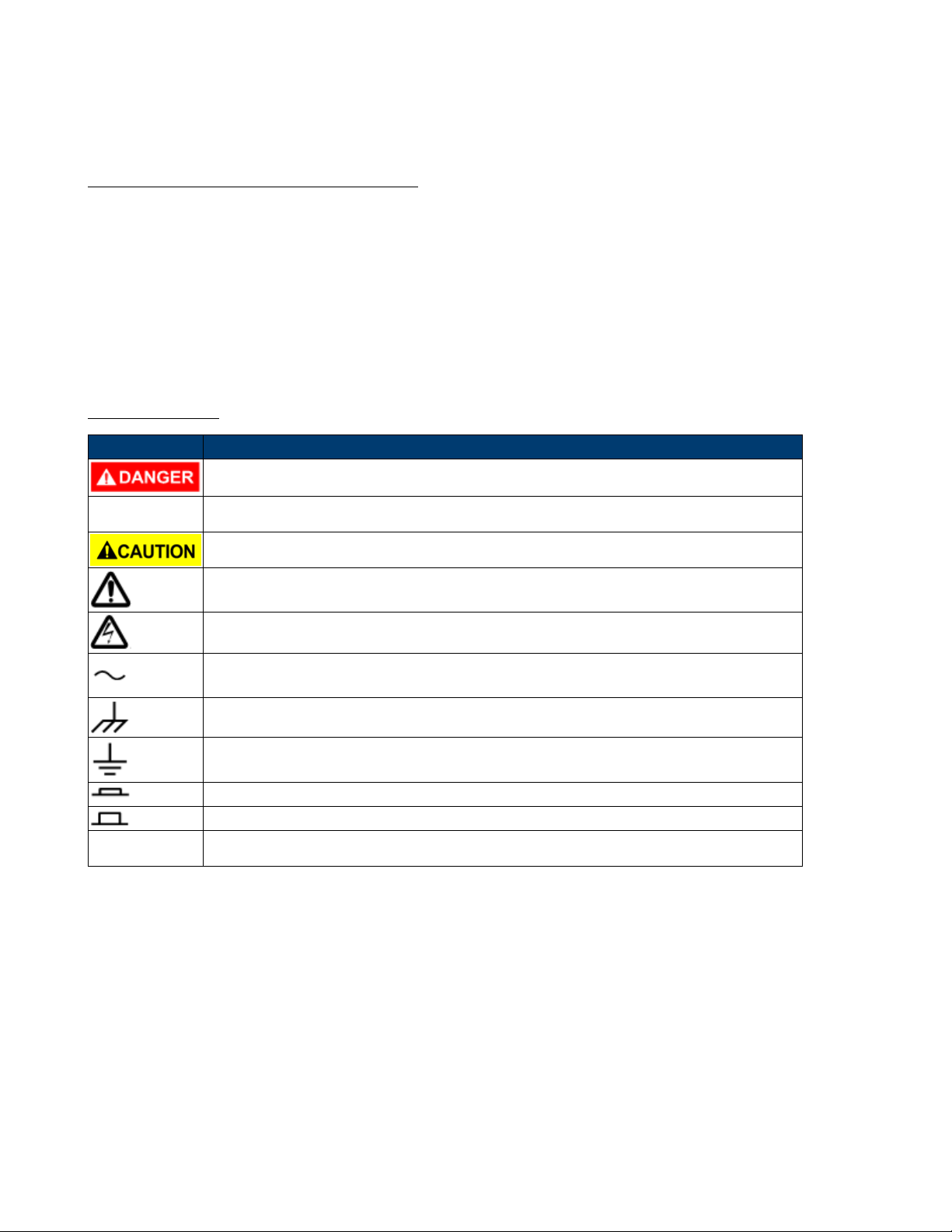
Safety Symbols
Symbol Description
indicates a hazardous situation which, if not avoided, will result in death or serious injury.
indicates a hazardous situation which, if not avoided, could result in death or serious injury
indicates a hazardous situation which, if not avoided, will result in minor or moderate injury
Refer to the text near the symbol.
Electric Shock hazard
Alternating current (AC)
Chassis ground
Earth ground
This is the In position of the power switch when instrument is ON.
This is the Out position of the power switch when instrument is OFF.
is used to address practices not related to physical injury.
5
Find Quality Products Online at: sales@GlobalTestSupply.com
www.GlobalTestSupply.com
Page 6

Contents
1 IMPORTANT SAFETY INSTRUCTIONS 7
1.1 Precautions 7
2 Product Overview 8
2.1 Package Contents 8
2.2 Power Requirements 8
2.3 Interface and Controls 8
3 Basic Operation 9
3.1 Setting Voltage and Current by Rotary Knob and Up/Down Keys 9
3.2 Setting Voltage and Current Using Keypad 9
4 Operating Instructions 10
4.1 Output Enable 1
4.2 Output Disable 10
4.3 Locking the Keypad and Rotary Knob 10
4.4 Unlocking the Keypad and Rotary Knob 10
4.5 Setting the RS-485 Address 10
4.6 Setting the Upper Voltage Limit 10
4.7 Enable Output at Power Up 11
4.8 Disable Output at Power Up 11
4.9 LCD Brightness 11
4.10 Enable/Disable SCPI 11
0
5 Using Programming Features 13
5.1 Preset Program 13
5.2 Setting Timed Program 13
5.3 Run Timed Programming 13
6 Maintenance 14
6.1 Recalibration 14
6.2 Troubleshooting 14
7 PC Software Control and Installation 15
7.1 USB Driver Installation 15
7.2 Software Installation 15
7.3 Multi-Unit Control 16
7.3.1 Connect Multiple Power Supplies to PC with RS-485 16
7.4 Software Setup and Conguration 16
7.4.1 Setup a new instrument 17
7.4.2 Enable SCPI protocol 19
7.4.3 Internal Timed Program 19
7.4.4 External Timed Program 20
7.4.5 Internal Preset Memory 20
7.4.6 Data Logging 21
7.4.7 Data Log Sampling Time and Voltage Upper Limit (UVL) Setting 21
8 Specications 25
9 Service Information 26
10 LIMITED ONE-YEAR WARRANTY 2
6
Find Quality Products Online at: sales@GlobalTestSupply.com
www.GlobalTestSupply.com
7
Page 7

IMPORTANT SAFETY INSTRUCTIONS
1. Do not use this apparatus near water.
2. Clean only with dry cloth.
3. Do not block any ventilation openings.
4. Do not install unit near any heat source or heating emitting devices.
5. Prevent the power cord from being walked on or pinched.
6. Unplug this unit during lightning storms or when unused for long periods of time.
1.1 Precautions
1. The unit must be used within its specied range.
The rated input voltages can be found on the rating label at the back of the unit. Before plugging into the AC supply,
check with the rating label.
2. This unit has a built-in Tracking O.V.P. (Over Voltage Protection) feature. In the event of the output voltage
becoming 10% greater than the set value, the O.V.P. will be triggered and the output power will be cut o and
>FAULT< warning will appear.
When you get this warning, switch o the unit and remove all loading.
If you switch the unit back on again it should resume normal operation. In the event that this problem persists contact
the manufacturer.
3. This unit has a built-in buzzer, which will sound when Over Temperature/Overload/Over Voltage Protection has been
triggered. When you get this warning, switch the unit o and remove all loading.
Check your load and output voltage setting.
Allow the unit to cool down for 30 minutes.
If you switch the unit back on it should resume normal operation.
In the event this problem persists contact B&K Precision for assistance.
4. Only use the supplied software and optional accessories with this unit.
5. Refer all servicing to manufacturer.
Warning! The maximum output voltage for Model 1698B is up to 60Vdc. It may be hazardous to touch metal part
of the terminals.
7
Find Quality Products Online at: sales@GlobalTestSupply.com
www.GlobalTestSupply.com
Page 8

Product Overview
2.1 Package Contents
• Power Supply (1696B, 1697B or 1698B)
• Power cord
• USB cable
2.2 Power Requirements
2.3 Interface and Controls
Parameter Value
Voltage 100 - 240 VAC
Frequency 50/60 Hz
Fuse 4A Slow Blow 250V
Item Description
1 Rotary control knob
2 Up/Down keys
3 Dual function control keys
4 Negative output terminal (black)
5 Chassis ground terminal (green)
6 Positive output terminal (red)
Front Panel Items Rear Panel Items
Figure 2.1 Interface and Controls
8
Find Quality Products Online at: sales@GlobalTestSupply.com
www.GlobalTestSupply.com
Item Description
1 Power Switch
2 Power Input
3 RS-485 Port
4 USB Port
Page 9

Basic Operation
3.1 Setting Voltage and Current by Rotary Knob and Up/Down Keys
1. Press to switch between setting voltage and current.
2. Rotate control knob or press and to set voltage/current level. Press the control knob to
toggle the cursor position.
3.2 Setting Voltage and Current Using Keypad
1. Press to switch between setting voltage and current.
2. Use the numeric keypad to to input voltage or current value.
3. Press Enter to conrm input values.
9
Find Quality Products Online at: sales@GlobalTestSupply.com
www.GlobalTestSupply.com
Page 10

Operating Instructions
4.1 Output Enable
1. Press .
2. Press within 3 seconds to ENABLE output .
4.2 Output Disable
1. Press .
2. Press within 3 seconds to DISABLE output .
4.3 Locking the Keypad and Rotary Knob
1. Press
2. Press
.
within 3 seconds to lock keypad and rotary knob .
4.4 Unlocking the Keypad and Rotary Knob
1. Press
2. Press within 3 seconds to unlock keypad and rotary knob .
4.5 Setting the RS-485 Address
1. Press
2. Press within 3 seconds to enter into RS-485 address set menu.
3. Use numeric keypad to to input an address from 1 to 255.
4. Press to conrm.
4.6 Setting the Upper Voltage Limit
10
Find Quality Products Online at: sales@GlobalTestSupply.com
www.GlobalTestSupply.com
Page 11

1. Press .
2. Press on the numeric keypad within 3 seconds to enter upper voltage limit adjustment menu. The rst line
says “Over” and the second if the voltage limit setting.
.
3. Use the numeric keypad
4. Press to conrm.
to to input upper voltage limit.
4.7 Enable Output at Power Up
This feature limits the upper level setting of output voltage to prevent inadvertent setting of high voltage, which may
damage your application. The value of this upper voltage range limit will be retained until further reset.
1. Press .
2. Press the up arrow key within 3 seconds to enable output on power up.
4.8 Disable Output at Power Up
1. Press .
2. Press the down arrow key
within 3 seconds to disable output on power up.
4.9 LCD Brightness
1. Press .
2. Press on numeric keypad within 3 seconds to enter brightness menu.
3. Use the rotary knob to raise or lower brightness from 0 to 9.
4. Press to conrm.
4.10 Enable/Disable SCPI
11
Find Quality Products Online at: sales@GlobalTestSupply.com
www.GlobalTestSupply.com
Page 12

1. Press .
2. Press on numeric keypad within 3 seconds to enter into SCPI enable/disable menu.
3. Use the rotary knob to toggle between ‘Y’ to enable SCPI and ‘N’ to disable SCPI command protocol
and use the extended protocol command set instead.
4. Press
to conrm.
12
Find Quality Products Online at: sales@GlobalTestSupply.com
www.GlobalTestSupply.com
Page 13

Using Programming Features
5.1 Preset Program
1. Press Program .
2. Use the numeric keypad thru to select a preset voltage and current value.
3. Use and to adjust preset voltage and current values.
4. Press within 3 seconds to conrm or press to exit program setting.
5.2 Setting Timed Program
The unit can be programmed to operate up to 20 timed subprograms (0-19 STEP as shown in the display). Each
subprogram is capable of running a preset operation period of 1 second to 99 minutes and 99 seconds with its own preset
voltage and current level. The timed subprogram can be set to run in sequence repeatedly from 1 to 9999 cycles or
innity run. You can run the unit through the sequence of subprograms for the input cycles number unless interrupted
by pressing the CLEAR key.
1. Press
2. Use to select a step to be modied.
3. Use the up and down keys to navigate between setting voltage, current, and time
4. Press Enter to conrm and exit.
then press on the numeric keypad to enter program setting menu.
5.3 Run Timed Programming
1. Press then press to select step program to run
2. Use to select the number of steps to run (2 to 20) and press .
Ex. Selecting step 3 means run from step 1 to step 3
3. Input the desired number of cycles from 0000 to 9999 using the numeric keypad or rotary knob, press to
conrm and begin timed program. Leave this setting on 0000 for innite cyclic run. Press to
terminate the program.
13
Find Quality Products Online at: sales@GlobalTestSupply.com
www.GlobalTestSupply.com
Page 14

Maintenance
6.1 Recalibration
The purpose of recalibration is to reduce the dierence between the set values and the displayed values on the LCD
display. Recalibration is only required when this dierence is greater than 0.1 V for voltage or -0.01 A / +0.02 A for
current.
6.2 Troubleshooting
Keypad and Dial do not work Check key lock symbol for lock state, unlock unit by pressing
then key, otherwise switch the unit o and then back on to see if the problem persists.
No output power Check the output for on/o symbol on the display. Press
Cannot get a high voltage
setting within the
rated maximum
“OUT OF RANGE”
keeps appearing
When keying in operations
the unit keeps exiting and
does not save inputs
then .
Check the upper voltage limit setting by pressing then . Adjust the
maximum voltage limit with the
Check if the setting is within the rated range. If this occurs during voltage setting, refer to troubleshooting solution to the previous problem.
Only 10 seconds are allowed for inputting and 3 seconds for operation mode settings.
and keys.
14
Find Quality Products Online at: sales@GlobalTestSupply.com
www.GlobalTestSupply.com
Page 15

PC Software Control and Installation
The PC software provides remote communication, data logging, front panel emulation, and timed programming capabilities
using the USB or RS-485 interfaces. The software supports Windows 7, 8, 8.1, 10.
Note: Do not connect both USB and RS-485 simultaneously.
7.1 USB Driver Installation
Figure 7.1 Download Link
1. Click “CP210X_USB_Driver.zip” to begin the download
2. Whem complete, right click on the .zip folder and click “Extract All…”
3. Depending on your system right-click and run the 32-bit or 64-bit installer as administrator to begin installation, see
Figure 7.2.
Figure 7.2 Install as the Administrator
7.2 Software Installation
15
Find Quality Products Online at: sales@GlobalTestSupply.com
www.GlobalTestSupply.com
Page 16

Figure 7.3
Figure 7.4
4. Click “Next” to continue. Figure 7.4
5. Select a destination location for the software. Figure 7.5
6. Select a location for the software shortcut.Figure 7.6
7. Check the box if you would like to create a desktop shortcut and click “Next” to continue. Figure 7.7
8. Click “Install” to begin installation.Figure 7.8
7.3 Multi-Unit Control
7.3.1 Connect Multiple Power Supplies to PC with RS-485
Use the RS-485 interface at the back of the power supply to daisy-chain up to 31 power supplies, see Figure 7.9. The
USB to RS-485 adapter shown in Figure 7.10 below is required.
7.4 Software Setup and Conguration
Connect the instrument to the PC with the supplied USB cable and power on the instrument. Ensure the drivers are
installed and the device is connected. To install the drivers, refer to Section 7.1 above for driver installation instructions.
16
Find Quality Products Online at: sales@GlobalTestSupply.com
www.GlobalTestSupply.com
Page 17

Figure 7.5
Figure 7.6
Also, the software uses the “SCPI” protocol, this must be enabled, see Section 7.4.2. With the instrument connected,
open the PC software. Figure 7.11 shows the screen to expect when the software starts. If there is already a saved
connection the software will automatically connect to the instrument.
7.4.1 Setup a new instrument
17
Find Quality Products Online at: sales@GlobalTestSupply.com
www.GlobalTestSupply.com
Page 18

Figure 7.7
Figure 7.8
• Select the “Setting” tab. See Figure 7.12
• Click on “Edit” to access the connection settings. See Figure 7.13
Note: When using USB: Only connection name, connection type, and COMM port are required. See Figure 7.14
18
Find Quality Products Online at: sales@GlobalTestSupply.com
www.GlobalTestSupply.com
Page 19

Figure 7.9 Connection diagram for multiple power supply control
Figure 7.10 Connection diagram between USB adapter and RS-485 connectors
• Type in a connection name, select USB from the drop down, and select the correct COMM port assigned by your PC.
Check the windows the device manager to determine the correct COMM port. In this case Windows has assigned
COM port 12. Click “Save” and the black display will light up to indicate a successful connection. See Figure 7.15
• If using RS-485, enter the three digit ID displayed on the RS-485 setting on the instrument.
− To set the RS-485 ID on the instrument press
or numeric keypad entry to edit ID. Press to save and exit.
If everything has gone well and the power supply is connected the software should look similar to Figure 7.16.
Display Panel
then and use the and
7.4.2 Enable SCPI protocol
Press then to enter SCPI setting. Use to move the selector down next to the
“n” and press to save and exit. See Figure 7.17
7.4.3 Internal Timed Program
Congure up to 20 user dened voltage, current, and duration steps save to the instruments internal memory, or read
parameters already stored in the internal memory for edit.
1. Click on the “Internal Timed Program” tab
2. Double-click on the desired cell and use the slider to set voltage and current values.
3. Set the number of cycles from 1 to 9999 and click to start, or click to save the program into the
instruments internal memory for future recall.
19
Find Quality Products Online at: sales@GlobalTestSupply.com
www.GlobalTestSupply.com
Page 20

Figure 7.11
Figure 7.12
7.4.4 External Timed Program
External Timed Program is completely controlled by the PC. The PC counts the step time and changes the specic
voltage and current levels of the power supply. Congure up to 20 user dened voltage, current, and duration steps.
1. Click on the “External Timed Program” tab. See Figure 7.20
2. Double-click on the desired cell and use the slider to set voltage and current values. Figure 7.21
3. Set step duration with the up/down buttons. The time can be set from 0 up to 9 hours 59 minutes and 59 seconds.
If time set left at 0 the step will be skipped. See Figure 7.22
4. Set the number of cycles from 0-999. Leave this setting at 0 for continuous loop.
5. Click
to start running the cycle.
7.4.5 Internal Preset Memory
Preset up to 9 voltage and current combinations into memory for quick output. Set voltage and current with the slider
bar and click to conrm. See Figure 7.23
20
Find Quality Products Online at: sales@GlobalTestSupply.com
www.GlobalTestSupply.com
Page 21

Figure 7.13
Figure 7.14
7.4.6 Data Logging
Data Log allows can be used to view present or stored output data, see Figure 7.24. Data can be saved and exported
as .CSV spreadsheet le or sent to a printer.
7.4.7 Data Log Sampling Time and Voltage Upper Limit (UVL) Setting
Under the “Setting” tab:
• Adjust the data log sampling time. 1S means the voltage, current, and power reading will be recorded every 1 second.
• Set the Voltage Upper Limit (UVL) and general output setting and timed programming setting will not exceed this
limit. See Figure 7.25
• Click to save.
Figure 7.15
21
Find Quality Products Online at: sales@GlobalTestSupply.com
www.GlobalTestSupply.com
Page 22

Figure 7.16 Figure 7.17 SCPI Selection
Figure 7.18
22
Find Quality Products Online at: sales@GlobalTestSupply.com
www.GlobalTestSupply.com
Page 23

Figure 7.19
Figure 7.20
Figure 7.21
23
Find Quality Products Online at: sales@GlobalTestSupply.com
www.GlobalTestSupply.com
Page 24

Figure 7.22
Figure 7.23
Figure 7.24
Figure 7.25
24
Find Quality Products Online at: sales@GlobalTestSupply.com
www.GlobalTestSupply.com
Page 25

Specications
Note: All specications apply to the unit after:
1. A temperature stabilization time of 15 minutes over an ambient temperature range of 23∘C±5∘C.
2. Short correction operation performed before making measurement.
Specications are subject to change without notice.
25
Find Quality Products Online at: sales@GlobalTestSupply.com
www.GlobalTestSupply.com
Page 26

Programmable DC Power Supplies
Models 1696B, 1697B & 1698B
Specifications
Note: All specifications apply to the unit after a temperature stabilization time of 30 minutes over an ambient temperature range of 23 °C ± 5 °C.
Model 1696B 1697B 1698B
Output Rating
Voltage 1 to 20 V 1 to 40 V 1 to 60 V
Current 0 to 10 A 0 to 5 A 0 to 3.3 A
Max Output Power 200 W
Load Regulation
Voltage ≤ 200 mV ≤ 200 mV ≤ 100 mV
Current ≤ 25 mA ≤ 15 mA ≤ 10 mA
Line Regulation
Voltage ≤ 10 mV
Programming/Readback Resolution
Voltage 10 mV
Current 1 mA
Power 1 mW
Meter Accuracy
Voltage Meter ± (1% + 2 counts for V > 5 V)
Current Meter ± (1% + 2 counts for I > 0.5 A)
Ripple & Noise
Voltage ≤ 30 mVp-p / ≤ 6 mVrms
Current ≤ 10 mArms
General
Efficiency ≥ 70%
AC Input 100 to 240 VAC ±10%, 50/60 Hz
Display Meter 4-digit voltage, current and power meter
I/O Interface USB (type B), RS485
Operating Temperature 32 °F to 104 °F (0 °C to 40 °C), ≤ 80% R.H
Safety LVD: EN61010-1:2010
Electromagnetic Compatibility EN55011, EN61000-3-2, EN61000-3-3, EN61000-6-1
Dimensions 7.6” x 3.85” x 8.46” (193 mm x 98 mm x 215 mm)
Weight 6.6 lbs. (3 kg)
Warranty 2 years
Included Accessories PC software, RS485 adapter, USB cable, and test report
Optional Accessories RS232 to RS485 adapter (ATR-2485)
3
Find Quality Products Online at: sales@GlobalTestSupply.com
www.GlobalTestSupply.com
 Loading...