

Page 1
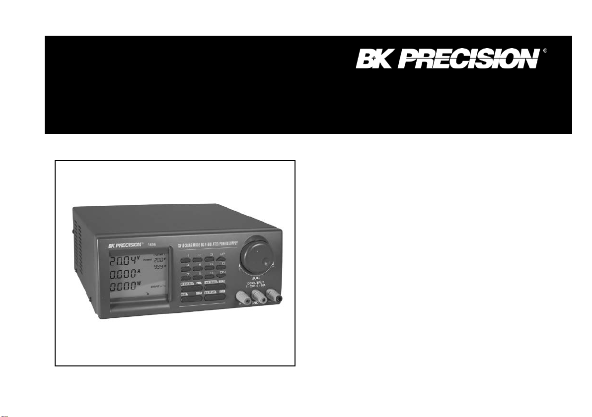
Model 1696/1697/1698
L ABORATORY GRADE
INSTRUCTION
MANUAL
MANUAL DE INSTRUCCIONES
Modelo 1696 / 1697 / 1698
SWITCHING MODE
PROGRAMMABLE DC
POWER SUPPLIES with
PC INTERFACE
Page 2

2
TABLE OF CONTENTS
1. IMPORTANT SAFETY INSTRUCTIONS & PRECAUTIONS FOR USE .............................................................. 3
2. SPECIFICATIONS ............................................................................................................................................ 4
3. INTRODUCTION .............................................................................................................................................. 5
4. CONTROLS & INDICATORS ........................................................................................................................... 6
5. GENERAL OPERATING PRINCIPLE .............................................................................................................. 8
6. OPERATING INSTRUCTIONS ......................................................................................................................... 9
6.1 SETTING OF OP ERATION M ODE ......................................................................................................... 9
6.2. MANUAL OP ERATI ON M ODE .......................................................................................................... 13
7. USING THE PRESET FEATURE .................................................................................................................... 14
7.1 OPER ATIN G THE TIME D PRO GRAM ................................................................................................ 15
7.2. RUNN ING THE TIME D PRO GRAM ................................................................................................... 16
8. MAINTENANCE .............................................................................................................................................. 19
8.1 RECALIBRATION ................................................................................................................................ 19
8.2 TROUBLE SHOOTING ......................................................................................................................... 20
9. PC INTERFACE CONTROL USER MANUAL ................................................................................................ 21
9.1. INTRODUCTION ................................................................................................................................. 21
9.2. SYSTEM REQUIREMENT AND INSTALLATION .............................................................................. 21
9.3. RS-232 IN TERF ACE OPER ATI ON ....................................................................................................... 22
9.4. RS-485 IN TERF ACE OPER ATI ON ....................................................................................................... 24
9.4.1 Configuration of each Power Supply .............................................................................................................. 29
9.4.2 Configuration of Multi Windows Analysis ..................................................................................................... 32
SERVICE INFORMATION ................................................................................................................................... 37
WARRANTY INFORMATION.............................................................................................................................. 38
Page 3

3
1. IMPORTANT SAFETY INSTRUCTIONS
1. Do not use this apparatus near water.
2. Clean only with dry cloth.
3. Do not block any ventilation openings.
4. Do not install unit near any heat source or heating emitting d evi ces.
5. Prevent the power cord from being walked on or pinched.
6. Unplug this unit during lightning storms or when unused for long periods of time.
PRECAUTIONS
1. The unit must be used within its specified range.
The rated input volt ages can be found on the rating label at the back of the unit.
Before plugging into the AC supply, check with the rating label.
2. This unit has a built-in Tracking O.V.P. (Over Voltage Protection) f ea tur e . I n the e ve nt of the output voltage be c om ing 10% greater than the se t
value, the O.V.P. wi11 be triggered and the output power will be cut off and > FAULT< warning will appear.
When you get this warning, switch off the unit and remove all loading.
If you switch the unit back on again it should resume normal operation. In the event that this problem persists contact the manufacturer.
3. This unit has a buzzer built inside. The buzzer will sound when Over Temperature/Overload/Over Voltage Protection has been triggered.
When you get this warning, switch off the unit and remove all loading.
Check your load and output voltage setting.
Allow the unit to cool down for 30 minutes.
If you switch the unit back on again, it should resume normal operation.
In the event this problem persists, the unit must be investigated by your agent.
4. Only use the supplied software and optional accessories with this unit.
5. Refer all servicing to manufacturer.
Warning!
The maximum output voltage for Model 1698 is up to 60Vdc.
It may be hazardous to touch metal part of the terminals.
Page 4

4
Specifications
1696
1697
1698
Output Voltage
1-20VDC
10-5A -40VDC
1-60VDC
Output Current
0-10A
0-5A
0-3.3A
Ripple & Noise (P-P)
25mV
25mV
25mV
Load Regulation
Voltage: 0.5%
Voltage: 0.5% +
Voltage: 0.5%
Line Regulation
50mV
50mV
50mV
Input Voltage
100 - 240 VAC, 50Hz / 60Hz
Display Meter
4 digit - display LCD Ammeter, Voltmeter and Power meter
Meter's Accuracy
1.5% + 2 counts
LCD Module Back Light
48 x 6mm
Cooling System
Thermostatic control fan
Protection Devices
Over Temperature, Tracking OVP
Approvals
CE
Dimension (HxWxD)
3.85 x 7.6 x 8.46" (98x193x21 5mm)
2. Technic al Specifications of models 1696, 1697, 1698
< 10 mAr ms
+ 200mV
Current: 0.2%
< 10 mAr ms
200mV
Current: 0.2%
< 10 mAr ms
+ 200mV
Current: 0.2%
Page 5

5
Weight
6.6lbs. (3Kg)
Accessory
PC Windows TM soft war e , R S -232 cable and Operation manual
3. INTRODUCTION
This series of laboratory grade, switching mod e, p rogr ammable p ower su p pl ies are i deal for rep eti tive test ro u tin es i n R&D , Produ ction, Product
Evaluation and various applications.
Information appearing on the large back-lit LCD makes the panel controls simple and easy to use in spi te of its sophisticated features.
Because of the MCU (Micro-Controller Unit) and the related softwar e, user re-calibration without opening the case is an added bonus.
When used with a standard PC, the supplied user friendly software and built in RS-232 interface provides two way communications improving
the functionality of these units.
Data logging with color graphic display in adjusting range Voltage, Current, Watts, and time periods are all valuable tools in data analysis.
Please keep this manual in a safe place and contact the manufacturer for any special requirements in appli cation software or other features.
Page 6
6
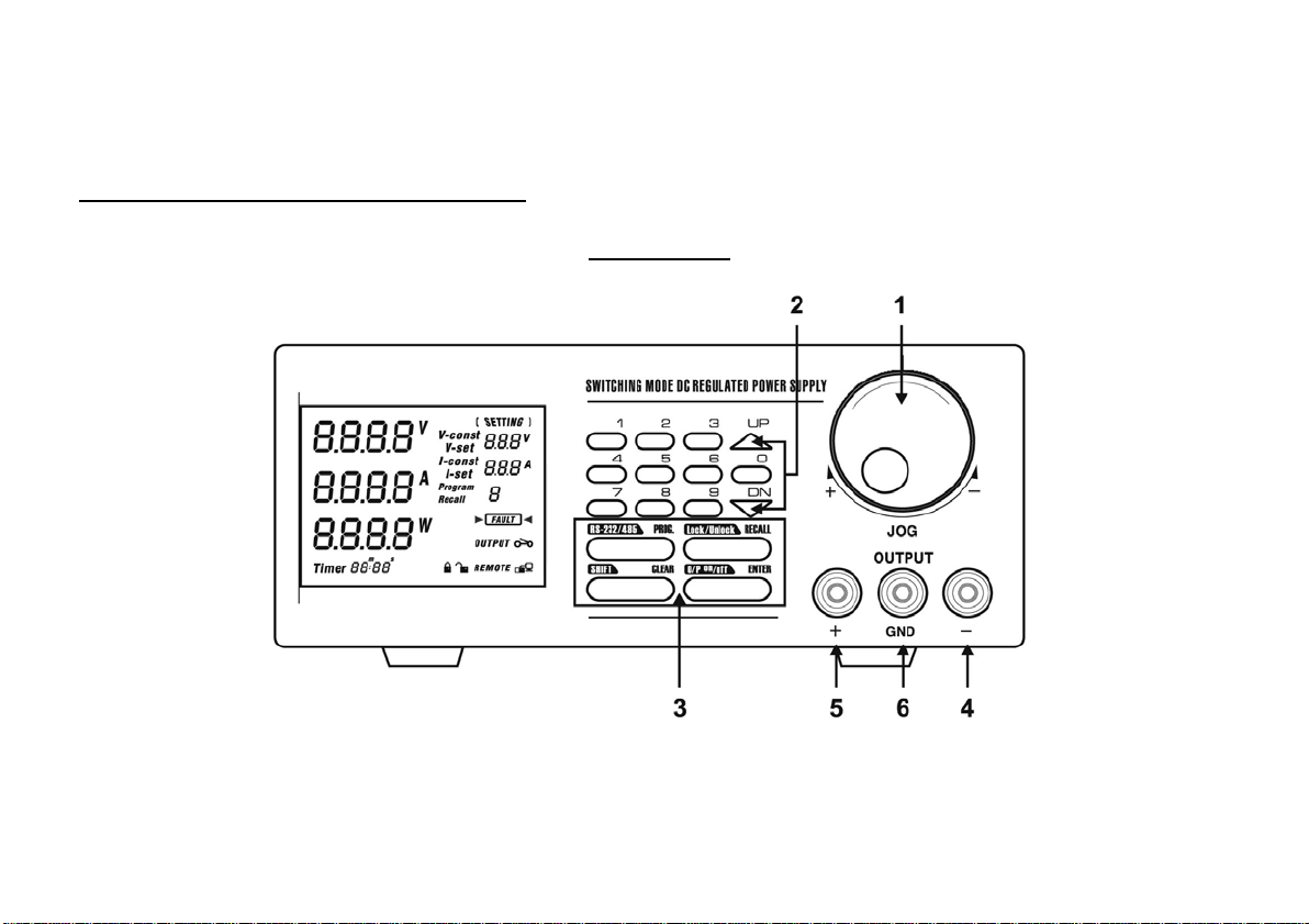
1. JOG DIAL
FRONT PANEL
4. CONTROLS AND INDICATORS
2. UP & DOWN KEY
3. DUAL FUNCTION CONTROL KEYS
4. BLACK COLOR NEGATIVE POLARITY OUTPUT TERMINAL
5. RED COLOR POSITIVE POLARITY OUTPUT TERMINAL
6. GREEN COLOR GROUND TERMINAL (connected to chassis)
Page 7
7
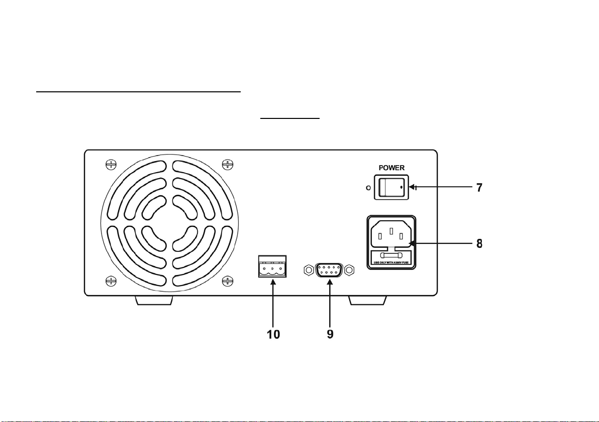
10. RS-485 PORT
BACK PANEL
4. CONTROLS AND INDICATORS
7. POWER SWITCH
8. AC 100 - 240 VAC PO WER SOCKE T WIT H INPUT P OWER FUS E
9. RS-232 PORT
Page 8

8
5. GENERAL OPERATION PRINCIPLE
There are four operation methods for this unit:
• Manual Operation
• Presets
• Timed Program
• PC Interface Mode.
•
The large Liquid Crystal Display will guide you through the various operations/procedures interactively once you understand the operation principle.
There are four Dual Function Control Keys for various operation modes and input states of the unit.
To change/set operation mode (output on /off, key lock & etc.), in most cases you need two Dual Function keys to complete the operation.
To change input values of various settings (voltage, current, preset number, cycles, time period & etc.), use the ENTER key to get ready and confirm the new settings.
Liquid Crystal Display
The back-lit display shows both the preset and the actual voltage, current levels at the output terminals; and status of constant current (CC) or constant voltage (CV) mode. Be
aware of new symbols appearing on the display while inputting. They will guide you and remind you of the correct procedure.
Example: Inputting values of various settings
When a new setting (voltage, current, time periods & etc.) is ready for inputting, the symbol for the related setting will appear on the display. After you key in the required value,
always follow by pressing ENTER to confirm or to complete the operation.
Presets and Timed Subprograms
This unit has the capacity to store 10 programs.
Page 9

9
Program 1 to 9 is for nine sets of Presets of voltage and current.
The program 0 is reserved for the 20 timed subprograms; ea ch is capable of storing 1 second to 99-minute operation period with its preset voltage and current levels.
The timed subprograms can be set to operate repeatedly in sequence from 1 to 232 cycles.
6. OPERATING INSTRUCTIONS
6.1 Setting of Operation Modes
Output On/Off Mode
1. Press SHIFT key.
The display will show Sh:Ft.
2. Press (O/P On/Off) key within 3 seconds.
Watch for the appearing On/Off symbol in the display to confirm your setting, otherwise repeat the above procedure.
Lock/Unlock the Keypad an d Jog Dial
1. Press SHIFT key.
The display will show Sh:Ft.
2. Press (Lock/Unlock) key within 3 seconds.
Watch for the appearin g Lock/Unlock symbol in the display to confirm your setting, otherwise repeat the above procedure.
PC Interface RS-232/RS4S5
1. Press SHIFT key.
The display will show Sh:Ft.
2. Press (RS232/485) key within 3 seconds.
3. Select desired PC Interface by the (RS232/485) key.
4. For RS 232 press RECALL to confirm setting.
5. For RS 485 enter 485 address followed by RECALL to confirm setting.
Page 10

10
Upper Voltage Limit Setting
This feature limits the upper level setting of output voltage to prevent inadvertent setting of high voltage, which may damage your a pplic a tion. The
value of this upper voltage range limit will be retained until further reset.
OPERATING INSTRUCTIONS
Precaution
Reset back to the maximum rated voltage of the unit is recommended to avoid false fault report of the unit
1. Press SHIFT and f ollow by 0 key.
2. T he display w ill show and the present upper v oltag e limit.
3. In put y our desi red v oltage f ollow ed by ENTER to confirm.
4. Recheck setting by repeating step 1.
CONTROL SYMBOLS ON DISPLAY
Page 11

11
OPERATING INSTRUCTIONS
Showing output terminals in ON/OFF state.
Showing key p ad & Jog dial are in Locked (de-activated) or Unlock ( activ a te d ) s tate.
Unit is ready for or has already been linked up with computer.
OUTPUT ENABLE/DISAB LE AT POWER UP
Press the SHIFT then the UP key.
This will enable the output at power up.
i.e. When you switch on the power supply,
the output is also on automatica lly with last set voltage value.
Press the SHIFT then the DN key.
This will disable the output at power up.
This is the default setting for safety reas on!!
WARNING SYMBOL ON DISP LAY
Over Voltage Protection is activated. Take off all loads. See Precautions at first page.
UPPER VOLTAGE LIMIT SYMBOL ON DISPLAY
Press the SHIFT then the 0 key.
The display on the LCD shows the unit ready for input of Upper Limit Range and the original set voltage.
Page 12

12
STANDARD OPERATION SYMBOLS
V- const Constant Voltage mode showing set voltage.
V- set This only appears voltage l evel is ready for setting.
I-set This only appears current level is ready for setting.
I-const This only appears when unit is in (CC) constant current mode.
They show the actual Volts, Amperes and Watts at the output terminals.
Page 13

13
6.2 Manual Operation Mode
In the Manual Operation Mode, once the voltage and current levels have been set, the unit wi11 keep these settings even after unit has been
switched off until further reset.
There are 3 ways to input a setting:
1. By the Jog Dial.
2. By the UP or DOWN key.
3. By the Key Pad.
For any wrong input, e.g. out of specification values, display will show "OUT OF RANGE" FOR ABOUT 3 SECONDS, then returns to
it's previous settings and ready for correct new input.
Manual Sett ing of Voltage and Current by Jo g Dial
1. To change the voltage setting, just rotate the Jog Dial, no other step is needed.
2. To change the current setting, press ENTER twice, the LCD will show I-set, push for desired value.
3. Press ENTER to confirm your chosen current setting.
Manual Sett ing of Voltage and Cur r ent by Up & Down Key
1. To change t he voltage setting, just press the Up & Down Key, no other step is needed.
2. To change the current setting, press ENTER twice, the LCD will show I-set, push the Up & Down key for desired value.
3. Press ENTER to confirm your chosen current setting.
Manual Sett ing of Voltage and Current by K ey Pad
1. Press ENTER.
Display will show V -set and the present voltage setting, key in the desired voltage level.
2. Press ENTER to confirm your chosen voltage setting and the display will show I-set.
3. You can key in the desired current setting now, if you do not want to change the current setting, you still need to press ENTER again
to confirm the new settings of voltage and current to complete the operation.
4. You must press the ENTER key 3 times in total even if you want to change the voltage, otherwise the unit will flash CANCEL
Page 14

14
and returns to its old settings
Note :
If during any of the a bov e key pa d opera t ions , you fall to input a se tt ing w it hin 10 s e c onds , t he unit will cancel the pr ocedur e a nd r e sume its pre v i ous
settings. You can exit any of the above operations by pressing the CLEAR key and the unit will revert to its previous settings.
7. USING THE PRESET FEATURES
PRESET PROGRAM SYMBOLS
Program Unit is ready for inputting of a Preset Program Number (19).
Recall Unit is ready for recalling a Pr eset Program Number.
The unit can store nine preset voltage and current settings.
Once programmed, these settings will be retained even when the unit is switched off.
Preset Programming
1. Press PROG key
The display will show Program_
Key in Program Number (1-9) at the keypad
2. The display will show :a) The newly keyed in Program Number.
b) The old settings of voltage and current with V-set ready for voltage to be reset.
c) Set the required voltage l evel than press ENTER to confirm.
d) The display will show I-set ready for current level to be reset.
e) Set required current level then press ENTER to confirm.
f) The program will automatically advance to the next Preset (as shown in the display Program_ section).
g) If you want to change the voltage and current setting of next Preset repeat procedure B to E, otherwise just press ENTER to
Page 15

15
go to the next Preset.
Whenever you want to determine Preset Programming you can press the CLEAR key to return to normal operation mode.
Selecting Presets
1. Press the RECALL key
The display will show Recall_
2. Press the number key (1-9).
The display will show the chosen Preset Number, its voltage and current level .
3. Press ENTER to activate .The unit will resume the chosen reset values.
If during any of the a bove procedures, you fail to input a setting within 10 seconds, the unit will cancel the procedure and resume the previous
settings. You ca n exit any of the above operations by pressing the CLEAR key and the unit will resume to its previous settings.
7.1 _ Operating the Timed Program
The unit can b e progr a mmed to op er a t e up to 2 0 timed sub p rogr a ms ( 1-19 STEP a s show n in t he dis p l ay). Ea ch s ubp r ogra m is cap ab l e of r unning a
preset operati on peri od of 1 s econd to 99 minutes a nd 99 s econds with it s own pres et volta ge and c ur
in sequence repea tedl y from 1 t o 232 cycl es. Y ou can r un the unit throug h the seq uence of sub progra ms for the inp ut cycl es number unles s int errup ted
by pressing the CLEA R key.
r
ent level. The timed sub progr am ca n be set to run
Programming the Unit
1. P ress the PROG key
2. P ress the 0 key (to get to the Timed Program Mode) and the displa y will show Program 0 StEP -..00
3. Inp ut subprogram number 0 to 19 and press ENTER to confirm.
4. Inp ut voltage level followed by ENTER to confirm and the disp lay will show I-set.
5. Inp ut current followed by ENTER t o confirm. The bottom left corner of the display will show Timer00m00s and the appearing minute symbol m.
6. Inp ut minute period (0-99) f ollowed by ENTER to confirm. The bottom left corner of the dis play will show Timer00m00s and the appeari ng
second symbol s.
7. Inp ut seconds period (0-99) followed by ENTER to confirm. The timed subprogram will automatically to next subprogram number ready input of
new settings.
8. Repeat procedure 4 to 7.
Page 16

16
9. A s ubprogram is confirmed to retain the new settings only when procedure 7 is completed.
10. You can always input zero time period as a terminating subprogram.
Note:
A. Once the subprograms are filled, the unit will return to manual operation mode.
B. Any subprogram with zero time period will become the Terminating Subprogram. For example, if you set the subprogram 7 with zero time
period, all the subprograms after 7 (i.e. 8, 9, 10-19) become non-existent.
The timed program will only cycle from subprogram 0 (STEP) to subprogram 6. You can use this feature to cut off the subprograms that
are not required for the sequence.
C. A subprogram is confirmed to the new settings only when procedure 7 is done.
D. During any of the above procedures, if you fall to input a setting within 10 seconds, the unit will exit from that procedure and return to
manual operating mode. For any wrong input, display will show OUT OF RANGE for about 3 seconds and then returns to its previous
procedure/settings ready for the correct new input.
7.2 Running the Timed Program Cycles
Once the desired numbers of subprograms have been filled as explained in the previous section, all the presets of voltage and current levels
and operation periods will be retained until further programming.
1. Press RECALL followed by the 0 key.
The display will show STEP 00 and Recall 0 and the settings of the first timed subprogram.
2. Use UP^ or DN/ keys to check the settings of all the timed subprograms.
3. Press ENTER and the display will show CYC-0000, the unit is ready for input of repetitive operation cycles.
4. Key in number of cycles required, 1-232 followed by ENTER to start the cycle operation.
5. The unit wi11 run through the Timed Subprogram 0 to 19 or 0 to any subprogram prior to the subprogram with zero rimed period.
6. The display will show the on-going cycle's count down time of operation period, actual and set voltage and current, number of cycles
executed.
7. You can also see the power (Watt) display if you press ENTER.
8. To return to the previous display press ENTER again.
Page 17

17
Note: Beware that the life span of the power supply is limited by the life of the relay, which is l00x 10,000 operation as stated by the relay
manufacturer.
TIMED PROGRAM SYMBOLS
1. Inputting Subprogr ams
Page 18

18
2. Symbols Running in a Timed Program Cycle
Unit is ready for the recheck of all subprogram settings.
Page 19

19
8. MAINTENANCE
8.1 RECALIBRATION
Introduction
This in-case recalibration is to reduce the difference between the Set values and the displayed values on the LCD Display. You only use the recalibration when
the differen ce is great er than 0.1V for volt age or -0.01A / +0.02A for current. The whole recalibration for voltages and current takes less than 15 minutes. It is
performed by a proprietary software using regressi on algorithm.
The recalibration software is compatible to Window XP, Me, 2000, 98SE, 98.
Installation of the recalibration software
1. In the ins tallation disk, run Setup.exe inside the folder of Re-calibration to install the recalibration software.
2. Follow the instructions in the setup program.
3. Finally a SDP Recalibration icon is created in the Program Menu.
Operation Instr uctio n
1. Ensure your PC is off; connect RS-232 to serial com. port of your PC and the power supply.
2. On Your Power Supply, press [SHIFT] key, then quickly press [RS232/485] key and select RS-232 followed by [ENTER] key.
3. Switch on your P C and run the SDP recalibration software.
4. Follow the instructions shown in the software.
Page 20

20
8.2 TROUBLE SHOOTING
1. Keypad and Dial do not work.
Check key lock symbol for lock state, unlock unit by pressing SHIFT then Lock/Unlock key, otherwise switch the unit off and then back on
to see if the problem persists.
2. No output power. Check the output f or on/of f symbol on the display. Pre ss SHIFT O/P ON/OFF key.
3. Cannot get a high voltage setting within the rated maximum. Check the upper voltage limit setting by pressing SHIFT then the 0 key. Reset to
the rated maximum voltage.
4. CANCEL symbol keeps appearing in all keying in operations. Keying in time may not be fast enough as only 10 seconds are allow e d f or data
inputting and 3 seconds for operation mode s e t ti ng.
5. OUT OF RANGE keep s appearing.
Check if setting is within the rated range.
If this occurs during voltage setting, see point 3.
Page 21

21
9. PC INTERFACE CONTROL USER MANUAL
9.1 Introduction
We integrate the micro-controller technology and our proprietary software with switching mode power technology to make this unit user friendly, time saving
and reliable power supply.
In PC interf a ce mode:
1. With our proprietary software one PC can perform remote access/control and output data logging for one programmable power supply with RS-232 or up to
31 programmable power supplies using RS-485 interface.
2. Outputs for dynamic loading like power surges can be recorded stored (also as XLS file) and displayed on the PC.
3. The PC can input, stored, retrieved, and transferred for all the data entries for the Timed Programs and the Memory Presets to the power supply. This
elimina tes the tedi ous pr ocess of key ing i n data f or dif fer ent gr oups of Time d Progr ams a nd Mem ory Pr eset s to the prog ram mable power supply.
4. Using the data logging function, the actual output voltage, amperes, watts, and time periods are recorded in the PC f or late r a naly sis . A dj usting t he s ca les of
voltage, c urre nt, pow er a nd t im e pa ram et ers c an high lig ht f urt he r gra ph ical ana ly sis.
9.2 System Requirement and Software Installation
1. CPU must be 450MHz or a bove.
2. Ram 128 MB.
3. Min. monitor screen size (area) 800 x 600 pixels.
4. Operating Sy stem W indow s® Xp, Me, 2000, 98SE, and 98.
Page 22

22
Installatio n of software
1. Run Setup.EXE with installation disk that comes with the unit.
2. Follow the instr ucti ons i n the set up pr ogram . Duri ng the runn ing of the set up prog ram, you may encounter "VERSION CONFLICT " remark s, ign ore it
and click y es t o c omple te the ins tal lat io n.
3. Finally a software icon is created in the pr ogram menu.
9.3 Operation Instruction for RS-232 Interface
1. Ensure that the PC is off; connect RS-232 to serial COM port of your PC and the power supply.
2. On your power supply, press t he [SHIFT] key, and then quick ly press [RS-232/485] key and select RS-232 (pressing the [RS-232/485] will
toggle between RS-232 and R S-485) followed by the [ENTER] key.
3. Switch your PC and run the program.
4. Click on Setup, and select the desired COM port. The default is set at COM port 1.
5. Click on Supply Connect, and then click on Single i n the drop menu.
6. An "Internal Timed Program" w indow wil l appear. Click on t he Data Log header on the top left and a window as s hown in Fig 1 wi ll appear.
Note:
When the right bottom comer of the dis play window s shows the UVI, value, connection to t he PC is made cor rectly and t he power supply is
operating normally.
Page 23

23
If it shows No Connection, check the following:
A. Go back to setup and check to see if the correct COM port has been assigned.
B. Check the power supply; make sure that the RS-232 has bee n selecte d.
C. Check the RS-232 cable connection.
D. Check to make sure that the power supply is tur ned on.
1. Setting
Once you bring up the software you can your desired sample time from
1 second up from the drop menu.
Data log Sampling Time
You can set your output voltage upper limit value to further safeguard
your low voltage applications.
Voltage Upper Lim it Se tt in g
2. Data Log window
A). You can use the Data Log window to view present output data or
stored data.
B). All the parameters at the bottom of the window display can be
changed by direct entry from the PC (with decimal point) and then
confirmed by the En ter key of the PC, or you can select the values
from the respective drop menu.
Parameters at the bottom of the Data Log window:
VMin Minimum voltage level.
V Max. Maximum voltage level.
Page 24

24
C Min Minimum current level.
C Max. Maximum current level.
V Min. Minimum power level in watt.
W Max. Maximum power level in watt.
3. Log Name
Click cursor on "Untitle", type in a name for your log. Note how the ###(5) icon changes to solid color.
4. Log Description
You can type in a detailed description of your log.
5. ##### Save Log
a) This function (and the icon) becomes effective when a Log Name is entered to replace the "Untitle".
b) By clicking on it will save the current data onto the PC.
c) To retrieve the data, go to the drop menu at (3) Log Description.
6. ##### Export to a file of xls type
Clicking on this icon will export the collected data (in the Save Log) in xls format to your PC.
7. Open file log of xls type
Clicking on this icon will import the collected data in xls format file to the software.
Page 25

25
8. XXX Delete
Clicking on this icon will delete the current or retrieve log on display at (3).
9. Print Log in xls format. P.22
THE DATA LOG WINDOW DISPLAY
Page 26

26
THE TIME FRAME CONCEPT OF DATA LOG
The data logging function starts when the software begins to run.
When T Min is set to zero seconds, it means the unit is on real time and the length of time lapsed is on the left hand side of the Time Minimum.
T Len is the length of time lapsed strafing from the Time Minimum.
Both parameters are adjustable so that any time period of the log can be displayed for analysis.
In the above example, T Min is set to 320 seconds and T length to 60 seconds, the display shows the output data starting at 320 seconds ago and
ending at the 380 second mark.
Page 27

27
serial no S2405000
##. #V
##. #A
0------0
GENERAL INFORMATION
Please refer to (Fig. 3) for the following description. 10.
Power Supply Description:
You may click on and assign an identification number for your power supply in use.
Actually this feature is used mainly when you have multiple power supplies in use via the RS-485.
11. Address:
This function is for multiple power supply applications. Each power supply has a unique address.
Ignore this function when using RS-232.
12. Voltage:
Enter the desired output voltage with decimal point.
13. Current:
Enter the de sired cu rrent limit wi th dec imal po int.
14. and 15.
Alternativ e way to adjust output voltage and current;
Left click increase s by 0.1 units.
Right cl ick de crease s by 0.1 un its.
Page 28

28
16. OUTPUT
232
Left click on icon will switch on or of f the outpu t.
Internal Timed Program
The PC interface remote mode really eliminates the tedious process in keying in groups of entries on the power supply. Because all the data are displayed together
in the monitor, the possibility of wrong entry is greatly reduced. Data of different groups can be classified, store, exported and retrieved for use at any time.
Retrieved data will be in red color if they ex ceed the present pre-set lim its of voltag e in upper v oltag e leve l or curre nt lim iting value.
The operation princi ple of Saving, Exporting, Filing, Deleting and Printing are the same as the Data L og function.
CLEAR TABLE ................................... D eletes a ll da ta on the displa y tab le to prepa re for new data e ntry .
SAVE TO PS ....................................... Transfers data from the Display table to the power supply.
READ FROM PS ................................. Get data from t he p owe r su pply .
RUN ....................................................... To run the timed program.
Running Cycle
Enter the numbe r of the desi red ru nni ng cyc les her e, Maximum cycles is 232.
Operation
1. Clear old data in the p ower s upply by f irst clic k [ Clear T able ] then click [Save to PS].
2. Check if n o data i n pow er sup ply by clicki ng [Re ad Fr o PS].
3. Enter data in the table us ing the Up/ Dow n/ L ef t/ Right keys on PC keyboard for new locations.
Page 29

29
4. Data exceeding the rated voltage and current w ill not be accepted.
5. Voltage exceeding set U VL ( up per o utp ut v olt age lim it) wil l n ot be ac ce pte d.
6. If retrieved or entered data exceeds upper or lower limit, setting of voltage, current, time the date will become red in color.
7. Transfer set data to power supply by clicking [Save to PS].
8. Click [Read Fro PS ] to i nitia te the [run ] comm and.
9. Set numbe r of des ire d [[ru nning cycl e] and c lick [run] .
Internal Preset Memory
The operation princi ple is the same as Internal Timed Program
To activate the selected pr es et, click on the box of the [Select] column then click Run.
If retrieved or entered data exceed present Upper or Lower limit set ting of voltage/current/time, the data becomes red in color.
9.4 Operation Instruction for RS-485 Interface
This interface operation is provided for remote access/control up to 31 power supplies. The setup procedures below:
9.4.1 Configuration of each Power Supply
1. Make certain that your PC is OFF. Use RS-485 plug to connect the power supplies to each other.
2. Check to see if the PC’s are interconnected. Use RS-485 to RS-232 converter to connect power supplies and the serial com port of
your PC (Fig. 4.).
Page 30

30
(FIG 4)
3. On your power supplies, press [SHIFT] key, then quickly press [RS-232/485] key and select RS-485.
4. A 3-digit number will be displayed. This number is the address assigned to the power supply and will be used in the
software.
5. Using the Key Pad to key in the address to assign for each power supply. The range is 001-031 and each of the power
supplies requires a unique address.
6. Switch on your PC and run the SDP program.
7. Click on set up and select the desired Com. Port 1.
8. In the tool bar, click on supply connect, then click on single in the drop menu.
9. An internal timed program window will appear.
10. By choosing the address in the a ddres s fiel d (Fi g . 5) y ou ca n input the desired sett ings for ea c h pow e r supply as given in Section
9.3 on page 12.
Page 31

31
9.4.2 Configuration of Multi Windows Analysis
1. In the tool bar, click on Supply Connect, then click on Multi in the drop menu.
2. A multi-window (Fig. 6) will appear.
3. Click on the icon (circled as below) a Multi Power Supply Connect Set Up (Fig. 7)
Page 32

32
(FIG. 6)
(FIG. 7)
4. Click on AutoScan Connect, the window will show the connected power supply indicated with “Y”.
5. Click on the box along the visible column to set the desired power supply to be visible in Multiple Data log window.
6. You can type in the description and location of your power supplies in the location and description column.
7. Click on Close Icon (at right bottom of window) to return to Multiple Data Log Window.
Page 33

33
1. Multi Alleyway Display one click and it
8. Remarks:
will display the Data Log and output data
of all the power supplies. It will activate
the icon 2, 3 & 4.
2. Show Digital and Log one click and it
will show both t he data log of all
connected power supplies.
Page 34

34
(FIG. 9)
You can click on the data log to select the power supply, the data log will highlight in blue and the address bar in the left bottom window will s how th e sele cted
power supply.
3. Show Digital - one click and will show the digital readings of all the connected power supplies.
4. Show Log - one click and it wi11 show the data log of all the connected power supplies.
5. Single Alley way Disp lays - one click and it will only di sp lay the Dat a L og of t he se lec te d pow er sup ply (F ig. 10). It will dis ab le t he ico n (2 , 3 , & 4). The
parameter at the bottom is the same as the Data Log Window i n RS-232 Interface on Page 14.
The All SP Tick box --- Tick to apply the parameters to all Data Log W ind ows in Mult i Alley way Display .
Page 35

35
6. Log Thumbnails Size Set Up - one cl ick a ll ows use r to adj ust the wi nd ow si ze of t he Da ta Log Wi ndow i n Mul ti A lle yw ay Disp lay . Use the sl ide rs t o
adjust the height and width of the Data Log Windows. Save 4:3 tick box can enable 4:3 screen size for the Data Log Windows.
7. Save Log:
a. Click on it and save log window (Fig. 13) will appear.
b. Click on the box along the Save column to choose the desired power supply data log to save.
c. Type in the table name.
d. Click save will save the current dat a onto the PC.
e. To retrieve data, go to the drop menu at Log (13).
f. To delete the lo g data, click on Delete Log icon (8).
Page 36

36
10. Delete Log
(FIG. 12)
SAMPLING TIME & AVAILABLE LOG TIME RECORD
The available log time record for each log is 1800 x sampling time.
It will delete log data in PC
11. Export to a file log of xls type
Click on this ico n to export the collec ted data in Data Log in xls form at to y our PC.
12. Open File Log of xls type
Click on this ico n to export the collec ted data to the SDP s oftware .
13. Close File Log of xls type
Click this icon to close the import xls format f ile.
14. Print Log
Prints log into xls format.
15. Log
Click on
16. Sample
Click to selec t t he sam pling t ime
17. SetV
Click and type to cha nge the v oltag e s ett ing of t he sele cte d p owe r su pply .
18. SetC
Click on it and ty pe i n t o cha nge the c urre nt set ting of the se lecte d powe r s up ply.
A sampling time of 3 seconds will allow log time record of up to 1800 x 3 = 5400 seconds overwrite the fast log record.
A sa mpli ng t im e of 6 se co nds w i1 1 al low log ti me r ec ord of u p t o 18 00 x 6 = 10800 seconds
Page 37

37
Service Information
Warranty Service: P lease return the product in the original packaging with proof of purchase to the address below. Clearly state in writing the
performance probl em and return any leads, probes, connectors and accessories that you are using with the device.
Non-Warranty Service: Return the product in the original packaging to the address below. Clearly state in writing the performance problem
and return any leads, probes, connectors and accessories that you are using with the device. Customers not on open account must include
payment in the form of a mon ey order or credit card. For the most current repair charges please visit www.bkprecision.com
“service/repair”.
Return all merchandise to B&K Precision Corp. with pre-paid shipping. The flat-rate repair charge for Non-Warranty Service does not include
return shipping. Return shipping to locations in North American is included for Warranty Service. For overnight shipments and non-North
American shipping fees pleas e contact B&K Precision Corp.
B&K Precision Corp.
22820 Savi Ranch Parkway
Yorba Linda, CA 92887
www.bkprecision.com
714-921-9095
Include with the returned i nstrument your complete return shipping address, contact n ame, phone numbe r and descripti on of problem.
and click on
Page 38

38
Limited One-Year Warranty
B&K Precision Corp. warrants to the original purchaser that its products and the component parts thereof will be free from defects in
workmanship and materials for a period of one year from date of purchase.
B&K Precision Corp. will, without charge, repair or replace, at its option, defective product or component parts. Returned product must be
accompanied by proof of the purchase date in the form of a sales receipt.
To obtain warranty coverage in the U.S.A., this product must be registered by completing a warranty registrat ion form on www.bkprecision.com
within fifteen (15) days of purchase.
Exclusions: This warrant y does not apply in the event of mis use or abuse of the product or as a result of unauthorized alterations or
repairs. The warranty is void if the serial number is altered, defaced or removed.
B&K Precision Corp. shall not be liable for any consequential damages, including without limitation damages resulting from loss of use. Some
states do not allow limitations of incidental or consequential damages. So the above limitation or exclusion may not apply to you.
This warranty gives you specific rights and you may have other rights, which vary from state-to-state.
B&K Precision Corp.
22820 Savi Ranch Parkway
Yorba Linda, CA 92887
www.bkprecision.com
714-921-9095
Page 39

39
22820 Savi Ranch Parkway
Yorba Linda, CA 92887
www.bkprecision.com
© 2006 B&K Precision Corp.
Printe d in
PN # 481-522-9-001
 Loading...