

Page 1
User’s Manual
SRP-S300
Thermal Printer
Rev. 1.02
http://www.bixolon.com
Page 2
Rev. 1.02
- 2 -
SRP-S300
■ Safety Precautions
In using the present appliance, please keep the following safety regulations in order to
prevent any hazard or material damage.
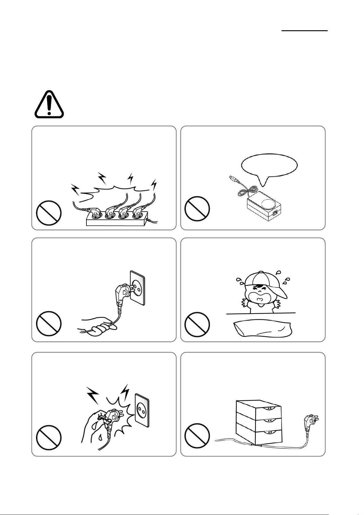
WARNING
Violating following instructions can cause serious injury or death.
Do not bend the cable by force or leave it under any
heavy object.
• A damaged cable can cause a fire.
Do not plug in or unplug with your hands wet.
• You can be electrocuted.
Keep the plastic bag out of children’s reach.
• If not, a child may put the bag on his head.
Do not pull the cable to unplug.
• This can damage the cable, which is the origin of a fire or a
breakdown of the printer.
You must use only the supplied adapter.
• It is dangerous to use other adapters.
Do not plug several products in one multi-outlet.
• This can provoke over-heating and a fire.
• If the plug is wet or dirty, dry or wipe it before usage.
• If the plug does not fit perfectly with the outlet, do not plug in.
• Be sure to use only standardized multi-outlets.
PROHIBITED
PROHIBITED
PROHIBITED
PROHIBITED
PROHIBITED
ONLY SUPPLIED ADAPTER
PROHIBITED
Page 3
Rev. 1.02
- 3 -
SRP-S300
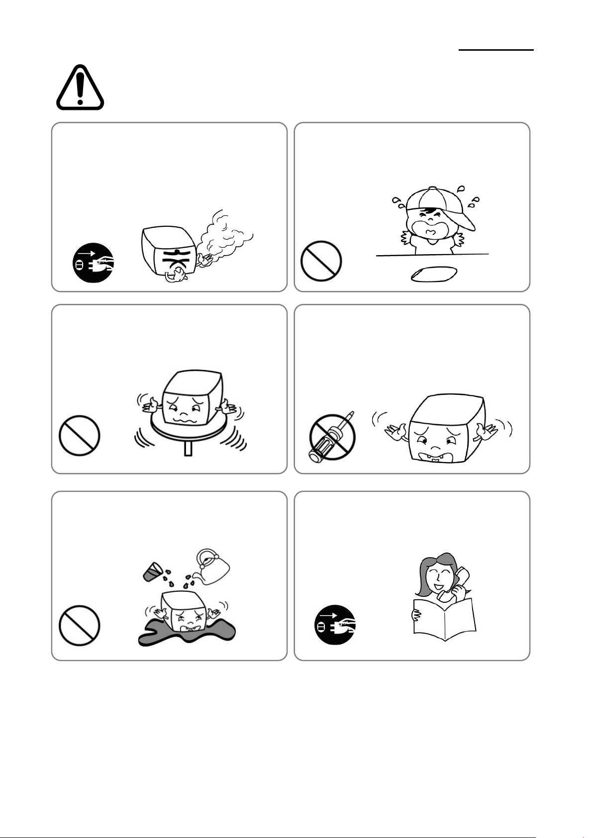
CAUTION
Violating following instructions can cause slight wound or damage the appliance.
Do not use the printer when it is out of order. This
can cause a fire or an electrocution.
• Switch off and unplug the printer before calling your dealer.
Do not let water or other foreign objects in the
printer.
• If this happened, switch off and unplug the printer before
calling your dealer.
Use only approved accessories and do not try to
disassemble, repair or remodel it for yourself.
• Call your dealer when you need these services.
• Do not touch the blade of auto cutter.
Install the printer on the stable surface.
• If the printer falls down, it can be broken and you can hurt
yourself.
Keep the desiccant out of children’s reach.
• If not, they may eat it.
If you observe a strange smoke, odor or noise from
the printer, unplug it before taking following
measures.
• Switch off the printer and unplug the set from the mains.
• After the disappearance of the smoke, call your dealer to
repair it.
TO UNPLUG
PROHIBITED
DISASSEMBLING
PROHIBITED
PROHIBITED
PROHIBITED
TO UNPLUG
PRINTER
PRINTER
PRINTER
PRINTER
DEALER
PRINTER
Page 4

Rev. 1.02
- 4 -
SRP-S300
■ Warning - U.S.A
This equipment has been tested and found to comply with the limits for a Class A digital
device pursuant to Part 15 of the FCC Rules. These limits are designed to provide
reasonable protection against harmful interference when the equipment is operated in a
commercial environment. This equipment generates uses, and can radiate radio frequency
energy and, if not installed and used in accordance with the instruction manual, may cause
harmful interference to radio communications. Operation of this equipment in a residential
area is likely to cause harmful interference in which case the user will be required to correct
the interference at his own expense.
■ Notice - Canada
This Apparatus complies with class “A” limits for radio interference as specified in the
Canadian department of communications radio interference regulations.
Get appareil est conforme aux normes class “A” d’interference radio tel que specifier par
ministre canadien des communications dans les reglements d’interference radio.
■ Caution
Some semiconductor devices are easily damaged by static electricity. You should turn the
printer “OFF”, before you connect or remove the cables on the rear side, in order to guard
the printer against the static electricity. If the printer is damaged by the static electricity, you
should turn the printer “OFF”.
■ Waste Electrical and Electric Equipment(WEEE)
This marking shown on the product or its literature, indicates that is should not
be disposed with other household wastes at the end of its working life, To
prevent possible harm to the environment or human health from uncontrolled
waste disposal, please separate this from other types of wastes and recycle it
responsibly to promote the sustainable reuse of material resources. Household
users should contact either the retailer where they purchased this product, or
their local government office, for details of where and how they can take this item for
environmentally safe recycling. Business users should contact their supplier and check the
terms and conditions of the purchase contract. This product should not be mixed with other
commercial wastes for disposal.
■ Rating Label Symbol Information
DC(Direct current)
Page 5

Rev. 1.02
- 5 -
SRP-S300
■ Introduction
The SRP-S300 Roll Printer is designed for use with electronic instruments such as system
ECR, POS, banking equipment, computer peripheral equipment, etc.
The main features of the printer are as follows:
1. Print at a max. speed of 170mm/s(Sticky, Re-stick,Linerless Extreme), 300mm/s(Receipt).
2. Low noise thermal printing.
3. Support of USB(built-in type), Ethernet, Serial, Parallel, Powered USB,
Wireless LAN, and Bluetooth interfaces.
4. Internal data buffer(data can be received and buffered while printing).
5. Control of external devices like cash registers through peripheral device drive circuit.
6. Barcode Printing.
7. Support of various print density settings(by changing memory switch settings).
It is advisable to read the contents of this manual carefully before using the printer for the
first time.
※ Note
The socket-outlet shall be near the equipment and it shall be easy accessible.
※ All specifications are subjected to change without notice.
This equipment is indoor use and all the communication hiring are limited to inside of the
building.
We at BIXOLON maintain ongoing efforts to enhance and upgrade the functions and quality
of all our products. In following, product specifications and/or user manual content may be
changed without prior notice.
Page 6

Rev. 1.02
- 6 -
SRP-S300
■ Table of Contents
1. Setting Up the Printer .................................................................................................... 7
1-1 Unpacking ............................................................................................................... 7
1-2 Connecting the Cables ............................................................................................ 8
1-2-1 USB Interface ................................................................................................. 8
1-2-2 Parallel Interface(IEEE1284) .......................................................................... 9
1-2-3 Serial Interface(RS232) ................................................................................ 10
1-2-4 Ethernet Interface ......................................................................................... 11
1-2-5 Wireless LAN Interface ................................................................................. 12
1-2-6 Powered USB Interface ................................................................................ 13
1-2-7 Bluetooth Interface ....................................................................................... 14
1-3 Drawer Cable ........................................................................................................ 15
1-4 Setting the Dip Switches........................................................................................ 16
1-4-1 DIP Switch 1 ................................................................................................. 16
1-4-2 DIP Switch 2 ................................................................................................. 17
1-5 Installing or Replacing the Paper Roll ................................................................... 19
1-6 Recommended Papers .......................................................................................... 21
1-7 Using the Printer .................................................................................................... 22
1-7-1 Control Panel ............................................................................................... 22
1-7-2 Mounting Partition(40,58,62mm) .................................................................. 23
1-7-3 Using of 83mm Paper Roll ........................................................................... 24
1-8 Setting Volume ...................................................................................................... 25
1-9 Using of Taken Sensor Function ........................................................................... 26
1-10 Removing Paper Jam .......................................................................................... 27
1-11 Connecting the computer .................................................................................... 28
1-12 Connecting the Power Supply ............................................................................. 28
2. Self Test ....................................................................................................................... 29
3. Hexadecimal Dumping ................................................................................................ 31
4. Specification ................................................................................................................ 32
5. Appendix ...................................................................................................................... 33
5-1 Cleaning Printer ..................................................................................................... 33
Page 7
Rev. 1.02
- 7 -
SRP-S300
1. Setting Up the Printer
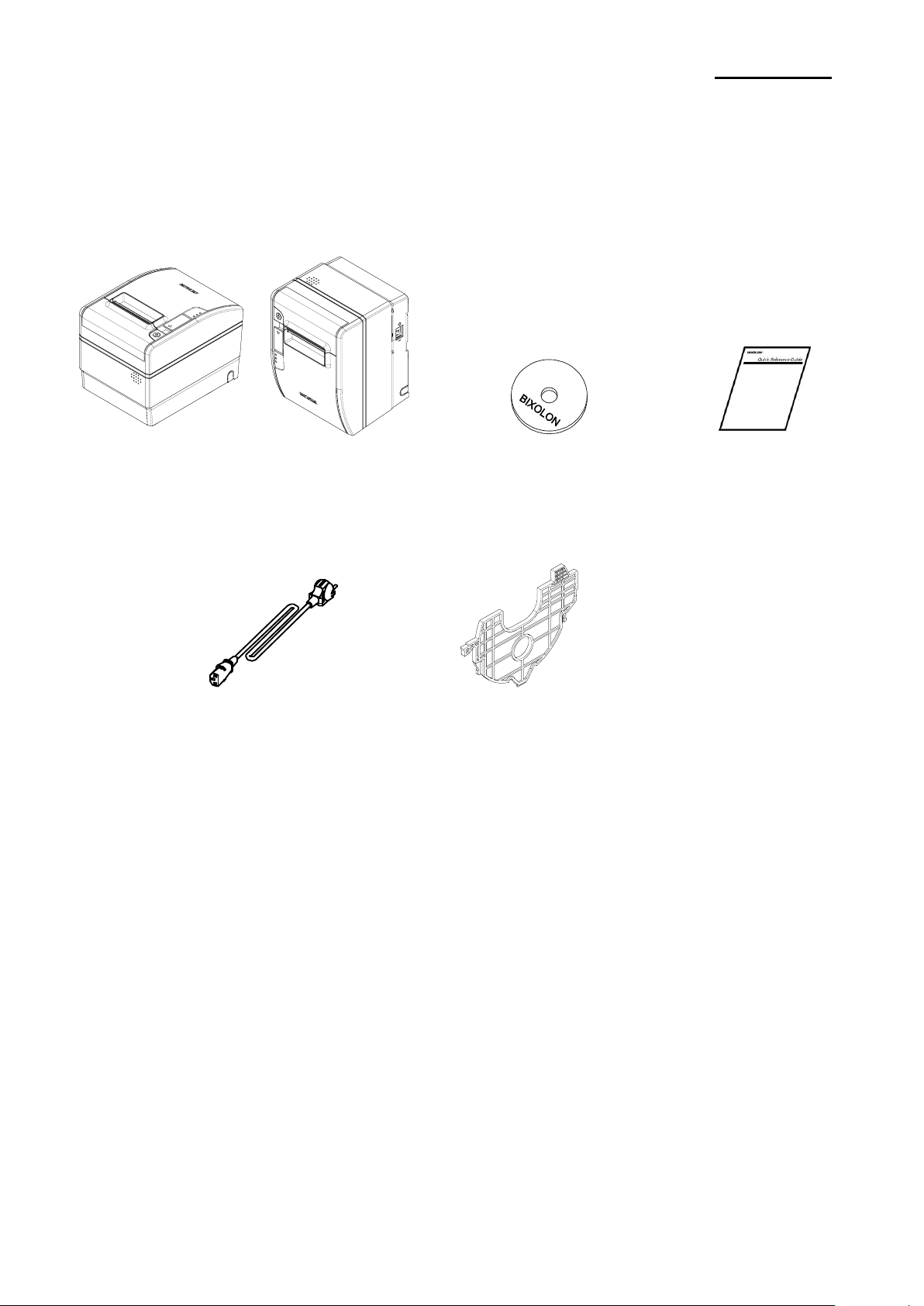
1-1 Unpacking
Your printer box should include these items. If any items are damaged or missing, please
contact your dealer for assistance.
SRP-S300 CD Installation Guide
Power cord Partition 2ea
Page 8
Rev. 1.02
- 8 -
SRP-S300
1-2 Connecting the Cables
Connect the printer to the host computer using the right interface cable that complies with
the specifications of the interface. The drawer to be used with the printer should meet the
specifications of the printer.
※ Caution
Before connecting any of the cables, make sure that both the printer and the host are
turned off.
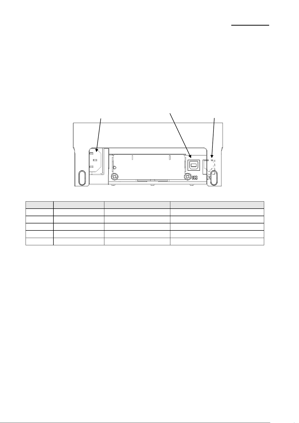
1-2-1 USB Interface
Pin No.
Signal Name
Designation(Color)
Function
Shell
Shield
Drain Cable
Frame Ground
1
VBUS
Red
Host Power: DC5[V] / 500[mA]
2
D-
White
Differential Data Line(D-)
3
D+
Green
Differential Data Line(D+)
4
GND
Black
Signal Ground
USB connector
Power
Drawer kick-out
connector
Page 9
Rev. 1.02
- 9 -
SRP-S300
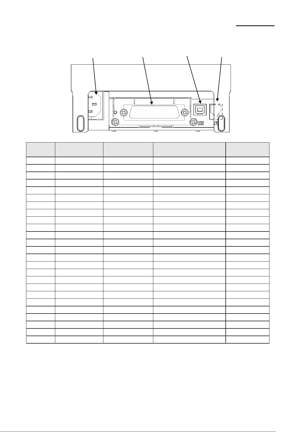
1-2-2 Parallel Interface(IEEE1284)
Pin No.
Source
Compatibility
Mode
Nibble Mode
Byte Mode
1
Host
nStrobe
HostClk
HostClk
2
Host / Printer
Data 0(LSB)
-
Data 0(LSB)
3
Host / Printer
Data 1
-
Data 1
4
Host / Printer
Data 2
-
Data 2
5
Host / Printer
Data 3
-
Data 3
6
Host / Printer
Data 4
-
Data 4
7
Host / Printer
Data 5
-
Data 5
8
Host / Printer
Data 6
-
Data 6
9
Host / Printer
Data 7(MSB)
-
Data 7(MSB)
10
Printer
nACK
PtrClk
PtrClk
11
Printer
Busy
PtrBusy / Data3,7
PtrBusy
12
Printer
Perror
AckDataReq / Data2,6
AckDataReq
13
Printer
Select
Xflag / Data1,5
Xflag
14
Host
nAutoFd
HostBusy
HostBusy
15 - NC
NC
NC
16 - GND
GND
GND
17 - FG
FG
FG
18
Printer
Logic-H
Logic-H
Logic-H
19~30 - GND
GND
GND
31
Host
nInit
nInit
nInit
32
Printer
nFault
nDataAvail / Data0,4
nDataAvail
33 - GND
ND
ND
34
Printer
DK_Status
ND
ND
35
Printer
+5V
ND
ND
36
Host
nSelectIn
1284-Active
1284-Active
USB connector
Parallel connector
Drawer kick-out
connector
Power
Page 10
Rev. 1.02
- 10 -
SRP-S300
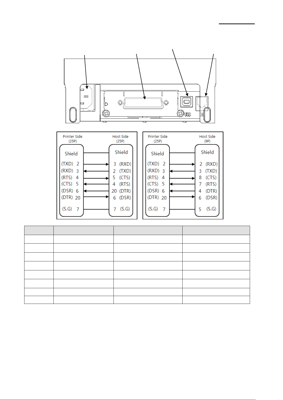
1-2-3 Serial Interface(RS232)
Pin No.
Signal Name
Direction
Function
FG
FG
-
Frame Ground
2
TxD
Output
Transmit Data
3
RxD
Input
Receive Data
4
RTS
Output
Ready To Send
5
CTS
Input
Clear To Send
6
DSR
Input
Data Set Ready
7
SG
-
Signal Ground
20
DTR
Output
Data Terminal Ready
Power
Serial connector
Drawer kick-out
connector
USB connector
Page 11

Rev. 1.02
- 11 -
SRP-S300
1-2-4 Ethernet Interface
Pin No.
Signal Name
Designation(Color)
Function
1
TD+
White Orange
Transmit +
2
TD-
Orange
Transmit -
3
TCT
White Green
Receive +
4
NC
Blue
-
5
NC
White Blue
-
6
RCT
Green
Receive -
7
RD+
White Brown
-
8
RD-
Brown
-
* If you push the function key, IP and MAC information can be obtained.
* Refer to the Network User Manual that is available from the BIXOLON website for more
detailed information.
Power
Ethernet connector
Ethernet Function key
USB connector
Drawer kick-out
connector
Page 12

Rev. 1.02
- 12 -
SRP-S300
1-2-5 Wireless LAN Interface
1-2-5-1 Wireless LAN Communication Specifications
Item
Specifications
Frequency
2.412~2.484 GHz
Channel
Channel 1~13
Protocol
802.11b, 802.11g, 802.11n
1-2-5-2 Connecting Wireless LAN
Printer can be connected to terminal devices with wireless LAN communication capability
(PDA, PC, smartphone, tablet PC, etc.).
* Refer to the Wireless LAN Connection Manual for more detailed instructions about how
to establish the connection.
Drawer kick-out
connector
Power
Wireless LAN module
USB connector
Page 13

Rev. 1.02
- 13 -
SRP-S300
1-2-6 Powered USB Interface
Pin No.
Signal Name
Function
Shield
Shield
Prevent Noise
1
PGND
Main Power Ground
2
VPP24V
Main Power
3
GND
Signal ground
4
D+
Data Line(D+)
5
D-
Data Line(D-)
6
VBUS
Host Power
7
VPP24V
Main Power
8
PGND
Main Power Ground
* Refer to www.poweredusb.org for detailed information related to the specifications of
cable and connector.
* Do not apply power when using Powered USB.(Powered USB uses its own power.)
* In case of using Powered USB interface, the other USB interface provided by default is
not useful. (In this case, USB communication is only available through the Powered USB)
Power
Powered USB connector
USB connector
Drawer kick-out
connector
Page 14

Rev. 1.02
- 14 -
SRP-S300
1-2-7 Bluetooth Interface
1-2-7-1 Bluetooth Communication Specifications
Item
Specifications
Frequency
2.402 ~ 2.480 GHz
Version
4.2
2.1 + EDR
Module Type
Class 1
1-2-7-2 Bluetooth Connection
Printer can be connected to terminal devices with Bluetooth communication capability
(PDA, PC, smartphone, tablet PC, etc.)
* Refer to the Bluetooth Connection Manual for more detailed instructions about how to
establish the connection.
Power
Bluetooth module
USB connector
Drawer kick-out
connector
Page 15

Rev. 1.02
- 15 -
SRP-S300
1-3 Drawer Cable
Connect the cash drawer connecting cable to the cash drawer connector located in the
back of the printer.
※ Warning
Use a cash drawer that meets the printer specifications.
Using an improper cash drawer may cause faults in the cash drawer and the printer.
Make sure to use a cash drawer with an internal coil resistance of 24 Ω(Ohm) or higher.
(The maximum current is 1A.)
The open signal time for the cash drawer should not exceed 0.8 seconds. After opening
the cash drawer, make sure to idle for at least 3.2 seconds(at least 4 times that of the
open signal time) before operating it.
Do not connect to a communication connector such as telephone line or modem as it
can damage the project.
※ Caution
Do not connect a telephone line to the drawer kick-out connector.
Otherwise, the telephone line and the computer may be damaged.
Pin No.
Signal Name
Direction 1 Frame Ground
-
2
Drawer Kick-out Drive Signal 1
Output
3
Drawer Open/Close Signal
Input 4 +24V
-
5
Drawer Kick-out Drive Signal 2
Output 6 Signal Ground
-
Page 16

Rev. 1.02
- 16 -
SRP-S300
1-4 Setting the Dip Switches
1-4-1 DIP Switch 1
• Serial Interface
SW
Function
ON
OFF
Default
1-1
Auto Line Feed
Enabled
Disabled
OFF
1-2
Flow Control
XON/XOFF
DTR/DSR
OFF
1-3
Data Length
7-bit
8-bit
OFF
1-4
Parity Check
Yes
No
OFF
1-5
Parity Selection
EVEN
ODD
OFF
1-6
Baud Rate(bps)
Refer to the following Table 1
OFF
1-7
ON
1-8
OFF
• Parallel / USB / Ethernet / Wireless LAN / Powered USB Interface
SW
Function
ON
OFF
Default
1-1
Auto Line Feed
Enabled
Disabled
OFF
1-2
Reserved
-
-
OFF
1-3
Reserved
-
-
OFF
1-4
Reserved
-
-
OFF
1-5
Reserved
-
-
OFF
1-6
Reserved
-
-
OFF
1-7
Reserved
-
-
ON
1-8
Reserved
-
-
OFF
• Bluetooth Interface
SW
Function
ON
OFF
Default
1-1
Auto Line Feed
Enabled
Disabled
OFF
1-2
Reserved
-
-
OFF
1-3
SSP Mode
Enabled
Disabled
OFF
1-4
Reserved
-
-
OFF
1-5
Reserved
-
-
OFF
1-6
Reserved
-
-
OFF
1-7
Reserved
-
-
ON
1-8
Reserved
-
-
OFF
• Table 1 – Baud Rate(bps) Selection
Baud Rate
1-6
1-7
1-8
Default
2400
ON
OFF
OFF
9600
4800
ON
OFF
ON
9600
OFF
ON
OFF
19200
OFF
OFF
OFF
38400
OFF
ON
ON
57600
OFF
OFF
ON
115200
ON
ON
ON
Page 17

Rev. 1.02
- 17 -
SRP-S300
1-4-2 DIP Switch 2
• SRP-S300L/T
SW
Function
ON
OFF
Default
2-1
Reserved
-
-
OFF
2-2
Black Mark Sensor
Disabled
Enabled
OFF
2-3
Internal Bell Control
Disabled
Enabled
OFF
2-4
Taken Sensor
*1)
Disabled
Enabled
OFF
2-5
Printing Density
Refer to the following Table 2
OFF
2-6
OFF
2-7
OFF
2-8
Auto External Buzz
Enabled
Disabled
OFF
*1)
Dip Switch 2-4 is only valid for Taken Sensing Model (SRP-S300T).
And then both taken sensing and back feeding are disabled when 2-4 is on.
• SRP-S300R
SW
Function
ON
OFF
Default
2-1
Reserved
-
-
OFF
2-2
Near End Sensor Control
Disabled
Enabled
OFF
2-3
Internal Bell Control
Disabled
Enabled
OFF
2-4
Reserved
-
-
OFF
2-5
Printing Density
Refer to the following Table 2
OFF
2-6
OFF
2-7
OFF
2-8
Auto External Buzz
Enabled
Disabled
OFF
• Table 2 – Print Density Selection
Printing Density
2-5
2-6
2-7
Default
Level 1
OFF
OFF
OFF
- Level 1 is
default
- Level 6 is
darkest
Level 2
ON
OFF
OFF
Level 3
OFF
ON
OFF
Level 4
ON
ON
OFF
Level 5
OFF
OFF
ON
Level 6
ON
OFF
ON
Page 18

Rev. 1.02
- 18 -
SRP-S300
※ Print Density
The print density can be set to one of eighteen different levels through virtual memory
switches.
Dip Switch
Density
Density Level
Light Dark
Speed
6(High Speed)
3
Level 1
5
6
Level 2
4
9
Level 3
3
12
Level 4
2
15
Level 5
1(Low Speed)
18
Level 6
Memory Switch
Density
Density Level
Light Dark
Speed
6(High Speed)
1 2 3
Level 1
5
4 5 6
Level 2
4
7 8 9
Level 3
3
10
11
12
Level 4
2
13
14
15
Level 5
1(Low Speed)
16
17
18
Level 6
* Choose Unified Utility or Self-Test mode to set the print density using the VMSM (Virtual
Memory Switch Management).
※Note
Change in DIP Switch settings are recognized only when the printer power is turned on or
when the printer is reset by using the interface. If the DIP Switch setting is changed after
the printer power is turned on, the change does not take effect until the printer is turned on
again or is reset.
Page 19

Rev. 1.02
- 19 -
SRP-S300
1-5 Installing or Replacing the Paper Roll
※ Caution
Use the paper rolls in supported sizes only. The printer may not recognize the availability
of the paper correctly if the paper roll is stuck to the tube.
1-5-1 Make sure that the printer is in standby mode and that no data is sent before
replacing the paper as it can lead to data loss.
1-5-2 Open the paper roll cover by raise the cover-open lever.
※ Caution
Do not open the print cover while the printer is operating, otherwise the printer may be
damaged.
1-5-3 Remove any existing used paper roll core when replacing the paper roll.
1-5-4 Insert the paper roll as shown in the following picture.
Page 20

Rev. 1.02
- 20 -
SRP-S300
1-5-5 Check the orientation of the roll paper when inserting it into the printer.
1-5-6 Pull out a small amount of paper as shown in the picture, and close the cover.
※ Caution
When closing the cover, hold down the center of printer cover firmly so that paper roll is
loaded correctly.
1-5-7 After the paper is rolled about 70mm, it switches to the black mark mode if there is
a black mark, otherwise, it is automatically set to the continuous paper mode.
1-5-8 Once the setting is completed, the paper will be cut automatically.
Page 21

Rev. 1.02
- 21 -
SRP-S300
1-6 Recommended Papers
Sticky, Re-stick,Linerless Extreme
- Iconex Sticky Media(USA):
Classic: 9023-1253, 9023-1232(80mm), 9023-1823, 9023-1397(58mm),
9023-1233, 9023-1818(40mm)
Classic High Tack: 9023-1254(80mm), 9023-1500(58mm), 9023-1258(40mm)
Classic High Temp: 9023-1267, 9023-1463 (80mm), 9023-1269(40mm)
Ultralite: 9023-1866(80mm), 9023-1410(58mm), 9023-1865(40mm)
Classic High Tack Plus: 9023-1846(80mm)
- Iconex Linerless Label(USA)
Linerless Extreme: 9023-1873, 9023-1708(40mm)
- MAX International Converters, Inc. MAXStick Products Ltd(USA)
Receipt
- TF50KS-E(Paper Thickness: 65μm): Nippon Paper Industries Co., Ltd.
- PD 150R(Paper Thickness: 75μm): New Oji Paper Mfg. Co., Ltd.
- PD 160R(Paper Thickness: 75μm): New Oji Paper Mfg. Co., Ltd.
- P350(Paper Thickness: 62μm): Kansaki Specialty Paper, Inc.(USA)
- P220AG(Paper Thickness: 65μm): Mitsubishi Paper Mills Limited
- P220A(Paper Thickness: 65μm): Mitsubishi Paper Mills Limited
- F5041(Paper Thickness: 65μm): Mitsubishi HitecPaper Flensburg GmbH
※ Caution
Use of papers other than those recommended above may damage TPH or degrade the
printing quality and our company is not responsible for the damage caused by nonrecommended papers. If you have to use other products, we recommend that you use
papers with a similar level of quality to the recommended ones.
Page 22

Rev. 1.02
- 22 -
SRP-S300
1-7 Using the Printer
1-7-1 Control Panel
○ POWER LED
The POWER light is on whenever the printer is on.
○ ERROR LED
This indicates an error.
○ PAPER LED
This light indicates the near end of the paper roll. Install a new
paper roll and the printer will continue printing. When the light
blinks, it indicates the self-test printing standby state or macro
execution Standby state when the macro execution command is
used.
○ FEED Button
Press the FEED button once to advance paper one line. You can
also hold down the FEED button to feed paper continuously.
Page 23

Rev. 1.02
- 23 -
SRP-S300
1-7-2 Mounting Partition(40,58,62mm) Position the partition on the front and back grooves and press the center part to fix it as
shown in the picture.
The position to secure the partition varies depending on the type of paper.
(Refer to the picture below.)
1. 58mm (2”) roll paper: mount 1 partition at Position #1.
2. 40mm roll paper: mount 2 partitions at Positions #1 and #2.
3. 62mm roll paper: mount 1 partition at Position #2.
※ The shape of the partition is the same for each type of roll paper.
※ Caution
After using narrower papers (e.g. 40, 58, 62mm width) than the maximum paper width of
80mm, please do not use any wider ones as it might affect printing quality due to uneven
platen roller abrasion.
Position #1
Position #2
Page 24

Rev. 1.02
- 24 -
SRP-S300
1-7-3 Using of 83mm Paper Roll Remove the side-mounted partition when using 83mm roll paper.
※ Caution
The default partition cannot be used in conjunction with the separately packaged partition.
Default Partition
Page 25

Rev. 1.02
- 25 -
SRP-S300
1-8 Setting Volume
Open the plate at the bottom of the printer and use a cross-head screwdriver to adjust the
volume.
Then, close the plate.
※ Caution
To mute the volume, turn it counter-clockwise all the way.
Plate
Plate
Decrease
the Volume
Increase
the Volume
Page 26

Rev. 1.02
- 26 -
SRP-S300
1-9 Using of Taken Sensor Function
When it comes to Taken Sensor, it will detect the paper not to feed next paper before user
detach it. This function will be supported by SRP-S300T.
Also, it’s available in Partial Cut Mode only but not in Full Cut Mode.
Page 27

Rev. 1.02
- 27 -
SRP-S300
1-10 Removing Paper Jam
1-10-1 When a paper jam occurs, turn the printer OFF and then back ON, open the cover,
and remove the jammed paper.
※ In case of a minor jam, it may be possible that the operating blade returns to the
original position and cover can be opened simply by turning the printer OFF and
then back ON.
Follow the steps shown below if the cover does not open after power cycling.
1-10-2 Turn the printer OFF.
1-10-3 Lift the paper rollout part of the COVER-CUTTER to remove it.
1-10-4 Turn the knob and insert the blade that sticks out using a cross-head screwdriver as
shown below.
1-10-5 Lift the cover-open lever and remove the jammed paper. Put the COVER-CUTTER
back in place.
1-10-6 Turn the printer ON and use it.
Page 28

Rev. 1.02
- 28 -
SRP-S300
1-11 Connecting the computer
Use the cable that comes with the printer to connect the printer to computers.
1-11-1 Plug the cable connector securely into the printer’s interface connector located
in the back of the printer.
1-11-2 Tighten the screws on the cable connector.(Only Serial Interface)
(Serial Cable Sample Image)
1-11-3 Connect the other end of the cable to the COM port of the PC.
1-12 Connecting the Power Supply ※ Caution
When connecting or disconnecting the power supply from the printer, make sure that
the power supply is not plugged into an electrical outlet. Otherwise you may damage
the power supply or the printer.
If the power supply’s rated voltage and your outlet’s voltage do not match, contact
your dealer for assistance. Do not plug in the power cord. Otherwise, you may damage
the power supply or the printer.
1-12-1 Make sure that the printer’s power switch is turned off, and the power
supply’s power cord is unplugged from the electrical outlet.
1-12-2 Check the label on the power supply to make sure that the voltage required by
the power supply matches that of your electrical outlet.
1-12-3 Plug in the power supply’s cable as shown below. Notice that the flat side of
the plug faces down.
※ Note
To remove the DC cable connector, make sure that the power supply’s power cord
is unplugged; then grasp the connector at the arrow and pull it straight out.
Power cord
Power
Page 29

Rev. 1.02
- 29 -
SRP-S300
2. Self Test
The self-test checks whether the printer has any problems. If the printer does not function
properly, contact your dealer. The self-test procedure is as follows:
2-1 Check whether the paper is inserted correctly.
2-2 Turn on the printer while depressing the Feed button. Self-diagnostics will begin.
2-3 The printer prints the current status of the printer such as the version of the ROM and
DIP switch setting.
2-4 The printer prints the current status and stops after printing the following statement.
(PAPER indicator keeps blinking.)
SELF-TEST PRINTING.
SELECT MODES BY PRESSING FEED BUTTON.
Continuous SELF-TEST : Less than 1 second
VMSM Selection : 1second or more
2-5 Press the FEED button for less than 1 second to perform “Continuous SELF-TEST”.
Hold down the FEED button for 1 second or longer to perform “VMSM Selection”.
2-5-1 Self-Test
2-5-1-1 If you press the FEED button for less than 1 second, the printer will print in the
preset character type.
2-5-1-2 The self-test completes automatically and cuts the paper after printing the following
line.
*** COMPLETED ***
2-5-1-3 The printer goes into standby mode when the self-test is complete.
2-5-2 Virtual Switch Setting Mode
2-5-2-1 When the printer goes into virtual switch-setting mode, the following lines will be
printed.
** VMSM Selection **
0: Exit and Reboot Printer
1: Print Current Settings
2: Set Print Density
3: Set Print Speed
4: Set Cutting Mode
5: Beep-once Alram
6: Continuous Alarm
7 Set Black Mark Cut Position
*1)
8or more: None
*1)
Sticky, Re-stick, Linerless Extreme Model only
Page 30

Rev. 1.02
- 30 -
SRP-S300
2-5-2-2 Make sure to press the FEED button to perform the above functions.
2-5-2-2-1 Step 1: The number indicates the number of times the FEED button needs
to be pressed. Make sure to press it for less than 1 second.
2-5-2-2-2 Step 2: Hold down the FEED button for 1 second or longer to enter the
selected item. If there is no selected item in Step 1, select “0: Exit
and reboot printer” to exit.
2-5-2-3 When the new settings are applied, hold down the FEED button for 1 second
or longer to save the changes. Cut the paper when the following line is printed.
(If “0: Exit and reboot printer” is not performed, the new settings will not be saved.)
*** COMPLETED ***
2-6 The settings will take effect after the printer reboots.
※ Note
You can check whether the printer operates normally or not through self-diagnostics. You
can check printing quality, ROM version, and DIP switch settings through self-diagnostics.
Page 31

Rev. 1.02
- 31 -
SRP-S300
3. Hexadecimal Dumping
This function allows experienced users to see exactly what data is coming to the printer.
This can be useful in finding software problems. When you turn on the hexadecimal dump
function, the printer prints all commands and data in hexadecimal format along with a guide
section to help you find specific commands.
To use the hexadecimal dump function, follow these steps.
3-1 After making sure that the printer is off, open the cover.
3-2 Turn the printer on, while holding down the FEED button.
3-3 Close the cover, and then the printer enters the hexadecimal dump mode.
3-4 Select the hexadecimal printing function in the mode selection menu to move to the
hexadecimal printing mode.
3-5 Run any software program that sends data to the printer.
The printer will print all the codes it receives in a two-column format.
The first column contains the hexadecimal codes and the second column gives the
ASCII characters that correspond to the codes.
1B 21 00 1B 26 02 40 40 40 40
. ! . . & . @ @ @ @
02 0D 1B 44 0A 14 1E 28 28 28
. . . D . . . .(((
00 01 0A 41 0D 42 0A 43 43 43
. . . A . B . C C C
- A period(.) is printed for each code that has no ASCII equivalent.
- During the hex dump, all commands are disabled.
3-6 When the printing finishes, turn off the printer.
3-7 Turn on the printer and then the hexadecimal mode is off.
Page 32

Rev. 1.02
- 32 -
SRP-S300
4. Specification
Printing Method
Thermal Line Printing
Dot Density
203 dpi(8 dots/mm)
Paper Width / Printing Width
83mm
80mm or 72mm
80mm
72mm
62mm
60mm
58mm
48mm
40mm
32mm
Paper Width
79.5 ±0.5mm, 61.5 ±0.5mm,
57.5 ±0.5mm, 39.5 ±0.5mm,
82.5 +1,-0.5mm
Characters Per Line(Default)
48(Font A), 64(Font B), 64(Font C)
※ For 80mm Roll Paper
Printing Speed
Sticky, Re-stick, Linerless Extreme:
Max. 170mm/sec
Receipt: Max. 300mm/sec
Receive Buffer Size
4Kbytes
※ Note
Printing speed may become slightly slower depending on the data transmission speed
and the combination of commands.
Supply
Voltage
SMPS Input Voltage
100~240 VAC
Frequency
50/60 Hz
SMPS Output Voltage
+24 VDC/2.5A
Environmental
Conditions
Temperature
0 ~ 40 ℃(Operating)
-20 ~ 60 ℃(Storage)
Humidity
10 ~ 80 % RH(Operating)
10 ~ 90 % RH(Storage)
; Excluding papers
Life Span *)
Printer Head
Sticky, Re-stick, Linerless Extreme: 75km
Receipt: 150km
Auto Cutter
Sticky,Re-stick: 1,000,000 cuts
Receipt: 3,000,000 cuts
*) The specifications were determined based on operation at normal temperature using
designated paper on default settings. They are subject to change depending on
temperature or printing level.
*) The specifications were tested according to standard reliability.
Page 33

Rev. 1.02
- 33 -
SRP-S300
5. Appendix
5-1 Cleaning Printer
Paper dust inside the printer may lower the print quality. In this case clean the printer as
follows:
It is recommended to clean after every 30 rolls when using Sticky, Re-stick,
Linerless Extreme paper.
5-1-1 Open the printer cover and remove any paper.
5-1-2 Use a cloth soaked in alcohol solvent or Cleaning Card (Pen) to clean the printer
head and roller.
5-1-3 Wipe the paper sensor with a cotton swab or dry cloth.
5-1-4 Clean the Auto Cutter using a cloth soaked in alcohol solvent or Cleaning Card (Pen).
5-1-5 Insert a paper roll and close the printer cover.
 Loading...