

Page 1
Service Manual
SRP-F310/312
Front Exit Thermal Printer
Rev. 1.00
http://www.bixolon.com
Page 2

SRP-F310/312
■ Table of Contents
1. Precaution Segment...................................................................................................................................4
1-1 Safety Precautions..................................................................................................................................4
1-2 Servicing Precaution...............................................................................................................................5
1-3 Precaution for Electrostatically Sensitive Devices (ESDs) .....................................................................6
1-4 Operational Precautions .........................................................................................................................6
2. Installation and Operation .........................................................................................................................7
2-1 Installation...............................................................................................................................................7
2-1-1 AC Adapter Installation ....................................................................................................................7
2-1-2 Interface Cable Installation ..............................................................................................................7
2-1-3 USB Cable Installation .....................................................................................................................7
2-1-4 Cash Drawer Cable Installation .......................................................................................................7
2-1-5 ETHERNET Cable Installation.........................................................................................................8
2-1-6 Dongle(Usb A-Type) Cable Installation ...........................................................................................8
2-1-7 Cover Open Installation ...................................................................................................................8
2-1-8 Paper Roll Installation ......................................................................................................................8
2-2 Operation ................................................................................................................................................9
2-2-1 Setting the DIP switches..................................................................................................................9
2-2-2 Setting the DIP switch (RS-232C Serial Interface) .......................................................................... 9
2-2-3 Setting the DIP switch (IEEE1284 Parallel, USB Interface) ............................................................9
2-2-4 Hexadecimal Dumping...................................................................................................................10
2-2-5 The self Test Mode ........................................................................................................................10
2-2-6 Setting the Memory Switches ........................................................................................................12
3. Product Specifications.............................................................................................................................15
3-1 Appearance...........................................................................................................................................15
3-1-1 Printer Dimensions (mm) ...............................................................................................................15
3-1-2 AC Adapter Dimensions (mm) .......................................................................................................15
3-1-3 Feature Locations-SRP-F310/312 .................................................................................................16
3-2 General Specifications..........................................................................................................................17
3-3 Thermal Printer Specifications..............................................................................................................18
3-3-1 Printer Specification .......................................................................................................................18
3-3-2 Character Specification..................................................................................................................18
3-3-3 Paper Specification ........................................................................................................................19
3-3-4 Reliability and Environment Specification......................................................................................19
3-3-5 Printable Area ................................................................................................................................20
3-3-6 TPH (Thermal Printer Head) Specification ....................................................................................20
3-3-7 Other Component Specification.....................................................................................................21
3-4 SMPS Specifications ............................................................................................................................22
3-4-1 SMPS (Switching Mode Power Supply) Specification ...................................................................22
3-4-2 SMPS Output Connector ...............................................................................................................22
3-5 Interface Specifications.........................................................................................................................23
3-5-1 RS-232C Serial Interface...............................................................................................................23
3-5-2 IEEE1284 Parallel Interface...........................................................................................................25
3-5-3 USB2.0 Interface............................................................................................................................27
3-6 Cash Drawer Specifications..................................................................................................................30
3-6-1 Drawer Cable .................................................................................................................................30
3-6-2 Cable Connection ..........................................................................................................................30
3-7 ETHERNET Specifications ...................................................................................................................31
3-7-1 Ethernet..........................................................................................................................................31
3-7-2 WLAN.............................................................................................................................................32
Rev. 1.00
- 2 -
Page 3

SRP-F310/312
4. Hardware ...................................................................................................................................................33
4-1 Wiring Diagram .....................................................................................................................................33
4-2 Block Diagram.......................................................................................................................................34
4-3 Special Circuit Descriptions..................................................................................................................39
4-3-1 Power Circuit..................................................................................................................................39
4-3-2 RESET Circuit................................................................................................................................40
4-3-3 Buzzer and Cash Drawer Circuits..................................................................................................41
4-3-4 I/F PBA Detect Block Diagram.......................................................................................................42
4-3-5 RS-232C Communication Block Diagram......................................................................................42
4-3-6 Parallel Communication Block Diagram ........................................................................................43
4-3-7 USB Communication Block Diagram ............................................................................................. 43
4-3-8 DIP Switch Circuit ..........................................................................................................................43
4-3-9 Thermal Printer Head Circuit .........................................................................................................44
5. Disassembly and Assembly ....................................................................................................................45
5-1 Case lower block ..................................................................................................................................45
5-2 Case Upper block .................................................................................................................................48
5-3 Frame block ..........................................................................................................................................51
6. Adjustments and Maintenance................................................................................................................53
6-1 Adjustment............................................................................................................................................53
6-1-1 Remaining Roll Paper Adjustment.................................................................................................53
6-2 Maintenance .........................................................................................................................................54
7. Troubleshooting .......................................................................................................................................55
7-1 Troubleshooting flow chart....................................................................................................................55
7-1-1 POWER LED does not light...........................................................................................................56
7-1-2 Paper and Error led blink ...............................................................................................................57
7-1-3 Paper and Error led lit ....................................................................................................................58
7-1-4 Paper led lit ....................................................................................................................................59
7-1-5 Error led blink.................................................................................................................................60
7-1-6 Error led lit......................................................................................................................................61
7-1-7 Self test is not normal ....................................................................................................................62
7-1-8 Data from host is not printed normally ...........................................................................................63
7-2 Power Problem .....................................................................................................................................64
7-2-1 Printing Quality Problems ..............................................................................................................65
7-2-2 Printer Mechanism Problems......................................................................................................... 66
7-2-3 Auto Cut Mechanism Problems .....................................................................................................66
Rev. 1.00
- 3 -
Page 4

SRP-F310/312
1. Precaution Segment
1-1 Safety Precautions
1. Be sure that all of the built-in protective devices are replaced. Restore any missing protective shields.
2. When reinstalling the chassis and its assemblies, be sure to restore all protective devices including:
nonmetallic control knobs and compartment covers.
3. Make sure that there are no cabinet openings through which people – particularly children - might
insert fingers and contact dangerous voltages. Such openings include excessively wide cabinet
ventilation slots and improperly fitted covers and drawers.
4. Leakage Current Hot Check:
WARING: Do not use an isolation transformer during this test.
Use a leakage-current tester or a metering system that complies with American National Standards
Institute (ANSI C101.1, Leakage Current for Applications), and Underwriters Laboratories (UL Publications
UL1410, 59.7).
With the unit completely reassembled, plug the AC line cord directly into a 100VAC or 240VAC outlet of the
Adaptor.
With the unit’s AC switch first in the ON position and then OFF, measure the current between a
known Earth ground (metal water pipe, conduit, etc.) and all exposed metal part, including: metal cabinet,
frame, and screw-heads and printer. The current measure should not exceed 0.1 milliamp. Reverse the
power-plug prong in the AC outlet and repeat the test.
5. Design Alteration Warning:
Never alter or add to the mechanical or electrical design of the ECR. Unauthorized alterations might create
a safety hazard. Also any design changes or additions will void the manufacture’s warranty.
6. Components, parts and wiring that appear to have overhead or that are otherwise damaged should be
replaced with parts that meet the original specifications. Always determine the cause of damaged or
overheating and correct any potential hazards.
7. Observe the original lead dress, especially near the following areas: sharp edges, and especially the AC
and high voltage supplies. Always inspect for pinched, out-of-place, or frayed wiring.
Do not change the spacing between components and the printed circuit board. Check the AC power cord
for damage. Make sure that leads and components do not touch thermally hot parts.
8. Product Safety Notice:
Some electrical and mechanical parts have special safety-related characteristics, which might not be
obvious from visual inspection. These safety features and the protection they give might be lost if the
replacement component differs from the original-even if the replacement is rated for higher voltage,
wattage, etc.
Components that are critical for safety are indicated in the circuit diagram by shading, ( )or ( ).
Use replacement components that have the same ratings, especially for flame resistance and dielectric
strength specifications. A replacement part that does not have the same safety characteristics as the
original might create shock, fire or other hazards.
Rev. 1.00
- 4 -
Page 5

SRP-F310/312
1-2 Servicing Precaution
WARNING 1: First read the Safety Precaution section of this manual. If some unforeseen
circumstance creates a conflict between the servicing and safety precautions,
always follow the safety precaution.
WARNING 2: An electrolytic capacitor installed with the wrong polarity might explode.
1. Always unplug the unit’s AC power cord from the AC power source or the Power Switch off before
attempting to:
(a) Remove or reinstall any component or assembly,
(b) Disconnect an electrical plug or connector,
(c) Connect a test component in parallel with an electrolytic capacitor.
2. Some components are raised above the printed circuit board for safety.
An insulation tube or tape is
sometime used. The internal wiring is sometimes clamped to prevent contact with thermally hot
components. Reinstall all such elements to their original position.
3. After servicing, always check that the screws, components and wiring have been
correctly reinstalled.
Make sure that the portion around the serviced part has not been damaged.
4. Check the insulation between the blades of the AC plug and accessible conductive parts
(example: metal panels and input terminals).
5. Insulation Checking Procedure: Disconnect the power cord from the AC source and
turn the power switch
ON. Connect an insulation resistance meter (500V) to the blades of the AC plug.
The insulation resistance
between each blade of the AC plug and accessible conductive parts (see above) should be
greater than 1 mega-ohm.
6. Never defeat any of the B+ voltage interlock. Do not apply AC power to the unit
(or any of its assemblies)
unless all solid-state heat sinks are correctly installed.
7. Always connect an instrument’s ground lead to the instrument chassis ground before
connecting the positive lead; always remove the instrument’s ground lead last.
Rev. 1.00
- 5 -
Page 6

SRP-F310/312
1-3 Precaution for Electrostatically Sensitive Devices (ESDs)
1. Some semiconductor (solid state) devices are easily damaged by static electricity. Such components are
called Electrostatically Sensitive Devices (ESDs); examples include integrated circuits and some field-effect
transistors. The following techniques will reduce the occurrence of component damaged caused by static
electricity.
2. Immediately before handling any semiconductor components or assemblies, drain the electrostatic charge
from your body by touching a known earth ground. Alternatively, wear a discharging wrist-strap device.
(Be sure to remove it prior to applying power-this is an Electric shock precaution.)
3. After removing an ESD-equipped assembly, place it on a conductive surface such as aluminum foil to
prevent accumulation of electrostatic charge.
4. Do not use freon-propelled chemical. These can generate electrical charges that damage ESDs.
5. Use only a grounded-tip soldering iron when soldering or unsoldering ESDs.
6. Use only an anti-static solder removal device. Many solder removal devices are not rated as anti-static;
these can accumulate sufficient electrical charge to damage ESDs.
7. Do not remove a replacement ESD from its protective package until you are ready to install it.
Most replacement ESDs are packaged with leads that are electrically shorted together by conductive foam,
aluminum foil or other conductive materials.
8. Immediately before removing the protective material from the leads of a replacement ESD, touch the
protective material to the device will be installed.
9. Minimize body motions when handling unpacked replacement ESDs. Motions such as brushing clothes
together, or lifting a foot from a carpeted floor can generate enough static electricity to damaged an ESD.
1-4 Operational Precautions
1. The heating element of the printer mechanism’s thermal head and the driver IC are easily damaged.
Never allow these components to come into contact with metal or other hard objects.
2. Never touch the printer mechanism’s heating element with your hand. Doing so can damage the heating
element and affect proper operation.
3. The head and motor areas are very hot during and immediately after printing. Do not touch components
in these areas directly with your hand.
4. Do not use any paper other than these specified in this manual otherwise print head reliability and print
quality are affected adversely.
5. Thermal paper starts to color at around 70ºC. Take care to protect unused and printed thermal paper
against the affects of heat, light and characters on the paper to feed.
6. Take the roll paper out of the printer when you will not use the printer for a long time in a high
temperature and humidity environment.
Rev. 1.00
- 6 -
Page 7
SRP-F310/312
2. Installation and Operation
2-1 Installation
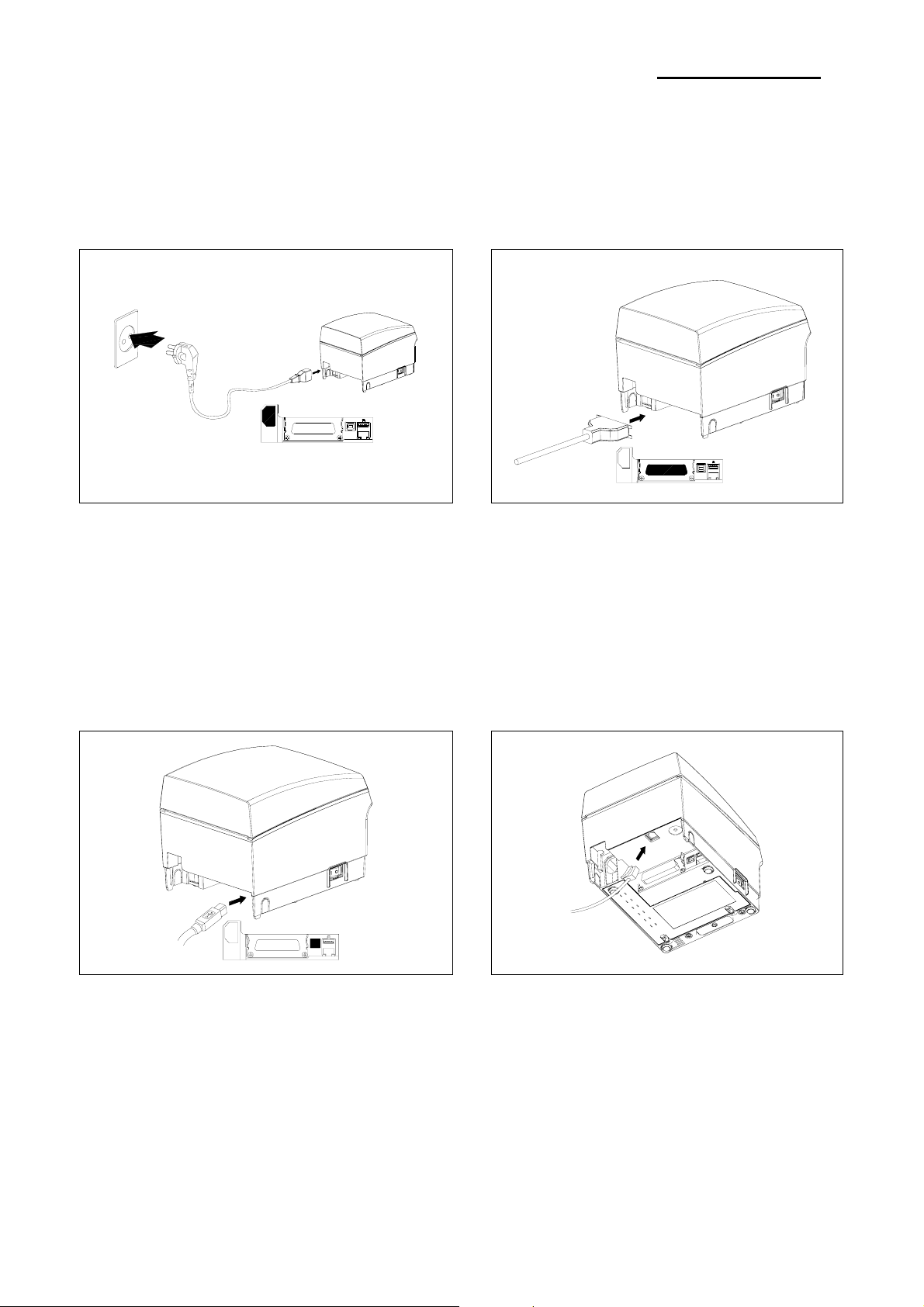
2-1-1 AC Adapter Installation
Figure 2-1 AC Adapter Installation
1. Make sure the printer is turned off with the
side of the switch.
2. Plug the power cord into the SMPS
on the printer.
3. Plug the AC Adapter power cord into the wall outlet.
2-1-3 USB Cable Installation
2-1-2 Interface Cable Installation
1. Turn off the printer, host ECR and Computer.
2. Plug RS-232, USB or Parallel Cable connector
into the I/F connector on the printer.
3. Tighten the screws on both sides of the connector.
4. Turn on the printer, host ECR and Computer.
2-1-4 Cash Drawer Cable Installation
Interface Cable
Figure 2-2 I/F Cable Installation
Interface connector
USB Connector
UAB-B Cable
Figure 2-3 USB B-TYPE Cable Installation
1. Turn the printer off.
2. Plug USB cable connector into
the connector on the printer.
Figure 2-4 Cash Drawer Cable Installation
1. Turn the printer off.
2. Plug the cash drawer cable connector into
the connector on the printer.
(To remove the cash drawer cable, press
the clip on the connector, grasp the connector
and pull it out.)
Rev. 1.00
- 7 -
Page 8
SRP-F310/312
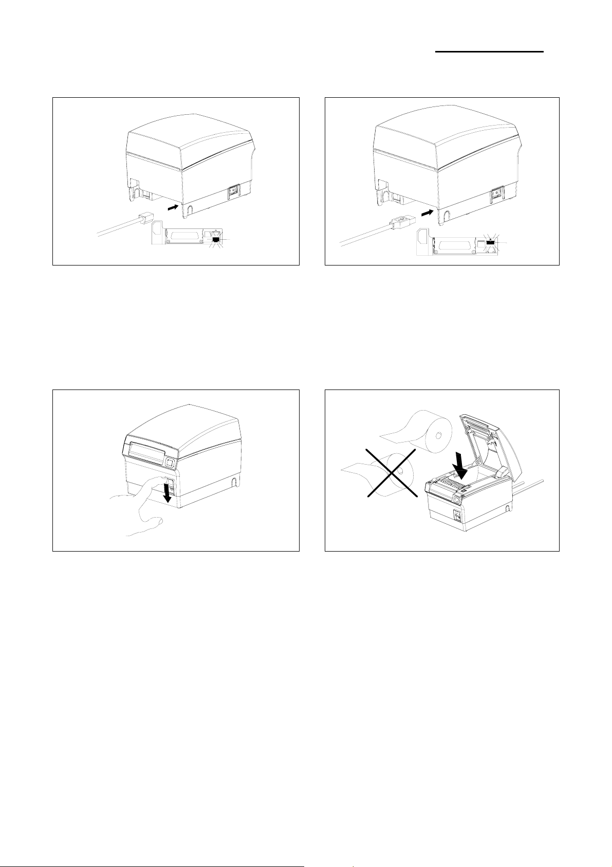
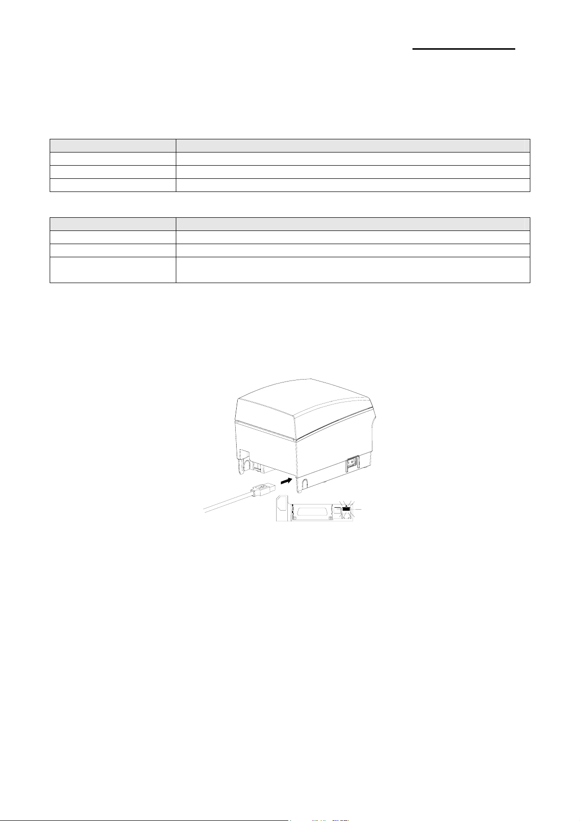
2-1-5 ETHERNET Cable Installation
Interface Connector
Figure 2-5 ETHERNET Cable Installation
1. Turn the printer off..
2. Plug the ETHERNET Cable into
the connector on the printer.
2-1-7 Cover Open Installation
2-1-6 Dongle(Usb A-Type) Cable Installation
Dongle Cable
Figure 2-6 Dongle Cable Installation
1. Turn the printer off..
2. Plug the Dongle Cable into
the connector on the printer.
2-1-8 Paper Roll Installation
Figure 2-7 Cover Open Installation
1. Turn the printer off.
2. Push the Cover-open Button
Figure 2-8 Paper Roll Installation
1. Open the cover printer and remove the used
paper roll core if there is one.
2. Load the paper roll on the paper holder as
shown.
3. Close the cover printer.
Rev. 1.00
- 8 -
Page 9
SRP-F310/312
2-2 Operation
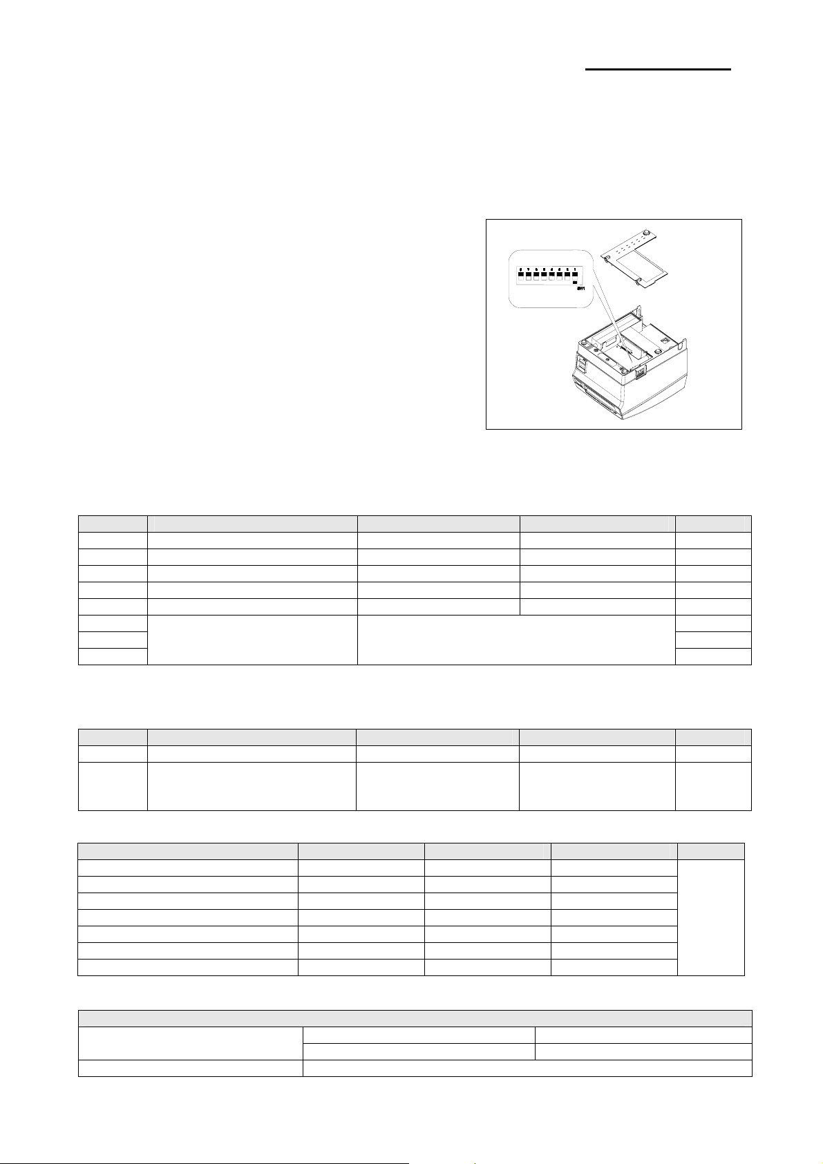
2-2-1 Setting the DIP switches
The DIP switches are located on the bottom of the printer. The DIP switches are used to set the printer to perform various
functions. Follow these when changing DIP switches setting:
1. Turn the printer power switch off.
Open the Cover .
2. Flip the DIP switches using tweezers or another marrow-ended
tool. Switches are in when up and off when off down in the
Figure 2-9.
3. The new setting takes effect when you turn on the printer.
Note: Always change DIP switch settings only when the
printer is turned off. Change made with the power on
have no effect and then on again.
Figure 2-9 Setting the DIP switches
2-2-2 Setting the DIP switch (RS-232C Serial Interface)
• DIP Switch
SW Function ON OFF Default
1-1 Auto-Cutter Selection Disable Enable OFF
1-2 Handshaking XON/XOFF DTR/DSR OFF
1-3 Data Length 7bits 8bits OFF
1-4 Parity Check Yes No OFF
1-5 Parity Selection EVEN ODD OFF
1-6 OFF
1-7 ON
Baud Rate Selection (bps) Refer to the following table
1-8
2-2-3 Setting the DIP switch (IEEE1284 Parallel, USB Interface)
• DIP Switch
SW Function ON OFF Default
1-1 Auto-Cutter Selection Disable Enable OFF
1-2
~
Reserved - - OFF
1-8
• Table – Baud rate (bps) Selection
Transmission Speed SW 1-6 SW 1-7 SW 1-8 Default
2400 ON OFF OFF
4800 ON OFF ON
9600 OFF ON OFF
19200 OFF OFF OFF
38400 OFF ON ON
57600 OFF OFF ON
115200 ON ON ON
※ Auto Cutter Enable / Disable selection
Dip Switch Set 1
SW 1-1
ON Auto Cutter Disabled
OFF Auto Cutter Enabled
Application Ignores Auto Cutter error for continuous printing.
OFF
9600
Rev. 1.00
- 9 -
Page 10

SRP-F310/312
2-2-4 Hexadecimal Dumping
This feature allows experienced users to see exactly what data is coming to the printer. This can be useful in
finding software problems. when you turn on the hexadecimal dump function, the printer prints all commands
and data in hexadecimal format along with a guide section to help you find specific commands.
To use the hexadecimal dump function, follow these steps:
1. After you make sure that the printer is off.
Open the cover.
2. Turn on the printer, while holding down the FEED button with beep.
3. close the cover, then the printer enters the hexadecimal dump mode.
Run any software program that sends data to the printer. The printer will print all the codes it
receives in a two-column format. The first column contains the hexadecimal codes and the second
column gives the ASCII characters that corresponds to the codes.
1B 21 00 1B 26 02 40 40 . ! . . & @ @
02 0D 1B 44 0A 14 1E 28 . . . D . . . . (
00 01 0A 41 0D 42 0A 43 . . . A . B . C
Note: A period(.) is printed for each code that no ASCII equivalent.
Note: During the hex dump all commands expect DLE EOT and DLE ENQ are disabled.
4. When the printing finishes, turn off the printer.
5. Turn on the printer and then the hexadecimal model is off.
2-2-5 The self Test Mode
The self-test checks whether the printer has any problem. If the printer does not function properly, contact
your dealer The self-test checks the following:
1. Make sure paper roll ahs been installed properly.
2. Turn on the power while holding down the FEED button with beep. The self-test begins.
3. Tue self-test prints the current printer status, which provides the control ROM version and the DIP
witch setting.
4. After printing the current printer status, self-test printing will print the following and pause (The
PAPER LED light blinds).
SELF-TEST PRINTING.
PLEASE PRESS THE FEED BUTTON.
5. Press the FEED button to continue printing. The printer prints a pattern using the built-in character
set.
6. The self-test automatically ends and cuts the paper after printing the following.
*** COMPLETED ***
The printer is ready to receive data as soon as it completes the self-test.
Rev. 1.00
- 10 -
Page 11

SRP-F310/312
SRP-F310 V01.00 STD 010110
================================
FPGA INFORMATION
BOARD VER.: 0x3
PROGRAM VER. : 0x11
DIP SWITCH STATUS
12345678
ON: *
OFF: ****** *
MEMORY SWITCH STATUS
MSW1 12345678
MSW2 12345678
MSW3 12345678
MSW4 12345678
MSW5 12345678
MSW6 12345678
MSW11 12345678
MSW12 12345678
SERIAL SETTING
BAUD RATE : 115200 BPS
DATA BITS : 8 BITS
PARITY CHECK : NONE
STOP BITS : 1 BIT OR MORE
HANDSHAKING : DTR/DSR
ETHERNET SETTING
MAC ADDR: 00:11:22:33:44:55
LAN_DHCP disabled
IP ADDR : 192.168.192.123
NETMASK : 255.255.255.0
GATEWAY : 192.168.192.254
WLAN SETTING
NETWORK: adhoc
AUTH: open
ENCRYPT: none
ESSID: BIXOLON_adhoc
WLAN_DHCP disabled
IPADDR: 192.168.1.1
NETMASK: 255.255.255.0
GATEWAY: 192.168.1.2
BUFFER CAPACITY: 512KBYTES
PRINT DENSITY
LIGHT [ 1 2 3 4 ] DARK
*
SELF-TEST PRINTING
PLEASE PRESS THE FEED BUTTON
ASCII
!"#$%&'()*+,-./0123456789:;<=>?@
"#$%&'()*+,-./0123456789:;<=>?@A
#$%&'()*+,-./0123456789:;<=>?@AB
$%&'()*+,-./0123456789:;<=>?@ABC
%&'()*+,-./0123456789:;<=>?@ABCD
&'()*+,-./0123456789:;<=>?@ABCDE
'()*+,-./0123456789:;<=>?@ABCDEF
()*+,-./0123456789:;<=>?@ABCDEFG
)*+,-./0123456789:;<=>?@ABCDEFGH
*+,-./0123456789:;<=>?@ABCDEFGHI
+,-./0123456789:;<=>?@ABCDEFGHIJ
,-./0123456789:;<=>?@ABCDEFGHIJK
-./0123456789:;<=>?@ABCDEFGHIJKL
./0123456789:;<=>?@ABCDEFGHIJKLM
/0123456789:;<=>?@ABCDEFGHIJKLMN
0123456789:;<=>?@ABCDEFGHIJKLMNO
123456789:;<=>?@ABCDEFGHIJKLMNOP
23456789:;<=>?@ABCDEFGHIJKLMNOPQ
3456789:;<=>?@ABCDEFGHIJKLMNOPQR
456789:;<=>?@ABCDEFGHIJKLMNOPQRS
56789:;<=>?@ABCDEFGHIJKLMNOPQRST
6789:;<=>?@ABCDEFGHIJKLMNOPQRSTU
789:;<=>?@ABCDEFGHIJKLMNOPQRSTUV
89:;<=>?@ABCDEFGHIJKLMNOPQRSTUVW
9:;<=>?@ABCDEFGHIJKLMNOPQRSTUVWX
PC437
ЗьйвдаезклипомДЕЙжЖфцтыщяЦЬ¢£¥Ptƒ
ьйвдаезклипомДЕЙжЖфцтыщяЦЬ¢£¥Ptƒб
йвдаезклипомДЕЙжЖфцтыщяЦЬ¢£¥Ptƒбн
вдаезклипомДЕЙжЖфцтыщяЦЬ¢£¥Ptƒбну
даезклипомДЕЙжЖфцтыщяЦЬ¢£¥Ptƒбнуъ
аезклипомДЕЙжЖфцтыщяЦЬ¢£¥Ptƒбнуъс
езклипомДЕЙжЖфцтыщяЦЬ¢£¥PtƒбнуъсС
зклипомДЕЙжЖфцтыщяЦЬ¢£¥PtƒбнуъсСª
клипомДЕЙжЖфцтыщяЦЬ¢£¥PtƒбнуъсСªº
липомДЕЙжЖфцтыщяЦЬ¢£¥PtƒбнуъсСªº¿
ипомДЕЙжЖфцтыщяЦЬ¢£¥PtƒбнуъсСªº¿┌
помДЕЙжЖфцтыщяЦЬ¢£¥PtƒбнуъсСªº¿┌ ┐
омДЕЙжЖфцтыщяЦЬ¢£¥PtƒбнуъсСªº¿┌ ┐½
мДЕЙжЖфцтыщяЦЬ¢£¥PtƒбнуъсСªº¿┌ ┐½¼
ДЕЙжЖфцтыщяЦЬ¢£¥PtƒбнуъсСªº¿┌ ┐½¼¡
ЕЙжЖфцтыщяЦЬ¢£¥PtƒбнуъсСªº¿┌ ┐½¼¡«
ЙжЖфцтыщяЦЬ¢£¥PtƒбнуъсСªº¿┌ ┐½¼¡«»
жЖфцтыщяЦЬ¢£¥PtƒбнуъсСªº¿┌ ┐½¼¡«»▓
ЖфцтыщяЦЬ¢£¥PtƒбнуъсСªº¿┌ ┐½¼¡«»▓▒
фцтыщяЦЬ¢£¥PtƒбнуъсСªº¿┌ ┐½¼¡«»▓▒░
цтыщяЦЬ¢£¥PtƒбнуъсСªº¿┌ ┐½¼¡«»▓▒░┃
тыщяЦЬ¢£¥PtƒбнуъсСªº¿┌ ┐½¼¡«»▓▒░┃┤
ыщяЦЬ¢£¥PtƒбнуъсСªº¿┌ ┐½¼¡«»▓▒░┃┤╡
ùÿÖÜ¢£¥
яЦЬ¢£¥PtƒбнуъсСªº¿┌┐½¼¡«»▓▒░┃┤╡╢╖
Pt
ƒбнуъсѪº¿┌ ┐½¼¡«»▓▒░┃┤╡╢
Rev. 1.00
Figure 2-10 The Self-Test Sheet
- 11 -
Page 12
SRP-F310/312
2-2-6 Setting the Memory Switches
This printer has Memory Switch set which is software switches. Memory Switch set has MSW1,
MSW2,MSW3, MSW4, MSW5, MSW6, MSW11, MSW12, Customize value.
Memory Switch setting utility can change the Memory Switch set to ON or OFF as shown in the table below
(default: all OFF):
Settings of the Memory Switch are stored in the NV memory: therefore, even if the printer is turned off, the
settings are maintained.
※ Notes: The Memory Switch is available to be changed by three methods:
- Memory Switch setting utility.
- Control from BXL/POS command.
MSW1
Switch Function ON OFF
MSW 1-1
MSW 1-2
MSW 1-3
MSW 1-4~5 -- Fixed to OFF
MSW 1-6
MSW 1-7
MSW 1-8 -- Fixed to OFF
MSW1-1~MSW1-3
MSW 1-3 MSW 1-2 MSW 1-1 Print speed Remark
OFF OFF OFF Print speed level 4 270 mm/s
OFF OFF ON Print speed level 3 250 mm/s
OFF ON OFF Print speed level 2 230 mm/s
OFF ON ON Print speed level 1 200 mm/s
MSW1-6~MSW1-7
MSW 1-7 MSW 1-6 Print density Remark
ON OFF Density level 3 Dark
OFF ON Density level 2
OFF OFF Density level 1 Light(Default)
MSW2
Switch Function ON OFF
1 Specification for Destination Double byte Country Single byte Country
2 Reserved -- Fixed to OFF
3~8 Code Page Selection Refer to following Table
Select Print Speed Refer to following Table
Select Print Density Refer to following Table
Rev. 1.00
- 12 -
Page 13
SRP-F310/312
MSW2-3~MSW2-8
MSW2-8 MSW2-7 MSW2-6 MSW2-5 MSW2-4 MSW2-3 Character Table
OFF OFF OFF OFF OFF OFF Page 0 437
(USA, Standard Europe)
OFF OFF OFF OFF ON OFF Page 1 Katakana
OFF OFF OFF ON OFF OFF Page 2 850 (Multilingual)
OFF OFF OFF ON ON OFF Page 3 860 (Portuguese)
OFF OFF ON OFF OFF OFF Page 4 863 (Canadian-French)
OFF OFF ON OFF ON OFF Page 5 865 (Nordic)
OFF OFF ON ON OFF OFF Page 16 1252 (Latin I)
OFF OFF ON ON ON OFF Page 17 866 (Cyrillic #2)
OFF ON OFF OFF OFF OFF Page 18 852 (Latin 2)
OFF ON OFF OFF ON OFF Page 19 858 (Euro)
OFF ON OFF ON OFF OFF Page 21 862 (Hebrew DOS code)
OFF ON OFF ON ON OFF Page 22 864 (Arabic)
OFF ON ON OFF OFF OFF Page 23 Thai42
OFF ON ON OFF ON OFF Page 24 1253 (Greek)
OFF ON ON ON OFF OFF Page 25 1254 (Turkish)
OFF ON ON ON ON OFF Page 26 1257 (Baltic)
ON OFF OFF OFF OFF OFF Page 27 Farsi
ON OFF OFF OFF ON OFF Page 28 1251 (Cyrillic)
ON OFF OFF ON OFF OFF Page 29 737 (Greek)
ON OFF OFF ON ON OFF Page 30 775 (Baltic)
ON OFF ON OFF OFF OFF Page 31 Thai14
ON OFF ON OFF ON OFF Page 32 Hebrew Old code
ON OFF ON ON OFF OFF Page 33 1255
(Hebrew New code)
ON OFF ON ON ON OFF Page 34 Thai11
ON ON OFF OFF OFF OFF Page 35 Thai18
ON ON OFF OFF ON OFF Page 36 855 (Cyrillic)
ON ON OFF ON OFF OFF Page 37 857 (Turkish)
ON ON OFF ON ON OFF Page 38 928 (Greek)
ON ON ON OFF OFF OFF Page 39 Thai16
ON ON ON OFF ON OFF Page 40 1256 (Arabic)
ON ON ON ON OFF OFF Page 41 1258 (Vietnam)
ON ON ON ON ON OFF Page42 Khmer(Cambodia)
OFF OFF ON OFF OFF ON Page47 1250 (Czech)
MSW3
Switch Function ON OFF
MSW 3-1
MSW 3-2
Select Emulation Refer to following Table
MSW 3-3
1~8 Reserved -- Fixed to OFF
MSW3-1~MSW3-3
MSW 3-3 MSW 3-2 MSW 3-1 Emulation Remark
OFF ON ON Emulation 4
OFF ON OFF Emulation 3
OFF OFF ON Emulation 2
OFF OFF OFF Emulation 1 BXL/POS
MSW4
Switch Function ON OFF
MSW 4-1 ASCII font selection Customized font Resident font
MSW 4-2 Extended font selection Customized font Resident font
MSW 4-3
MSW 4-4
Single byte Font Selection Refer to following Table
MSW 4-5
MSW 4-6
Double byte Font selection Refer to following Table
MSW 4-7
MSW 4-8 Reserved -- Fixed to OFF
Rev. 1.00
- 13 -
Page 14
SRP-F310/312
MSW\4-3~MSW4-4
MSW 3-4 MSW 3-3 Single byte Font Selection Remark
OFF OFF Font A 12x24
OFF ON Font B 9x17
ON OFF Font C 9x24
MSW\4-5~MSW4-7
MSW 4-7 MSW 4-6 MSW 4-5 Double byte font type Remark
OFF OFF OFF KS5601
OFF OFF ON SHIFT-JIS
OFF ON OFF BIG5
OFF ON ON GB2312
ON OFF OFF GB18030
MSW5
Switch Function ON OFF
MSW 5-1 Auto cutter function Full cutting Partial cutting
MSW 5-2 Reserved -- Fixed to OFF
MSW 5-3 2 color support Enable Disable
MSW 5-4 Auto Line Feed Enable Disable
MSW 5-5 Near-End Sensor Disable Enable
MSW 5-6 Reserved -- Fixed to OFF
MSW 5-7 Reserved -- Fixed to OFF
MSW 5-8 Reserved -- Fixed to OFF
MSW6
Switch Function ON OFF
MSW 6-1
MSW 6-2 Internal buzzer control Disable Enable
MSW 6-3
MSW 6-4 Reserved -- Fixed to OFF
MSW 6-5 Offline status condition Pulse mode Step mode
MSW 6-6 Select watermark printing function Enable Disable
MSW 6-7 Reserved -- Fixed to OFF
MSW 6-8 NearEnd sensor detect signal Enable Disable
MSW11
Switch Function ON OFF
11-1~8 Reserved -- Fixed to OFF
MSW12
Switch Function ON OFF
12-1~8 Reserved -- Fixed to OFF
Auto generate pulse to internal
buzzer
Internal buzzer with cash drawer
pulse
Enable Disable
Enable Disable
Rev. 1.00
- 14 -
Page 15
SRP-F310/312
3. Product Specifications
3-1 Appearance
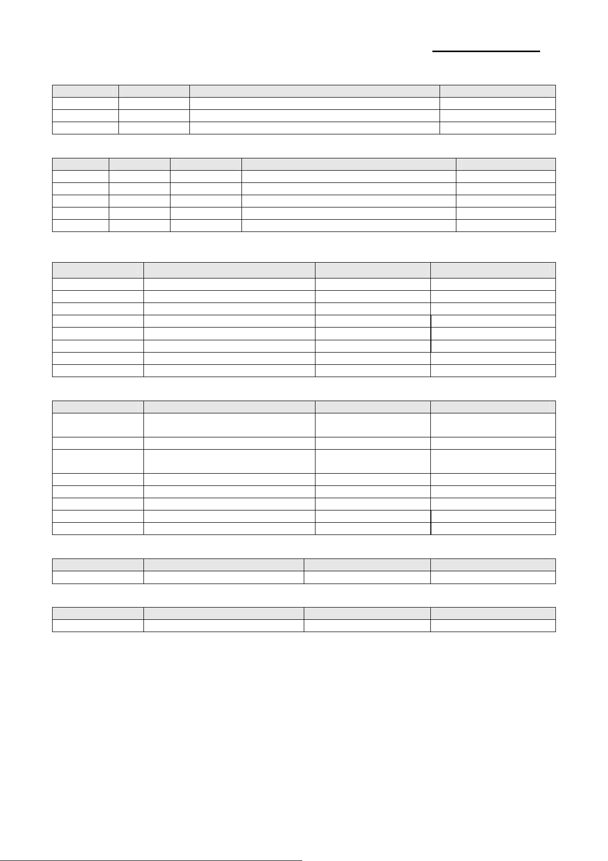
3-1-1 Printer Dimensions (mm)
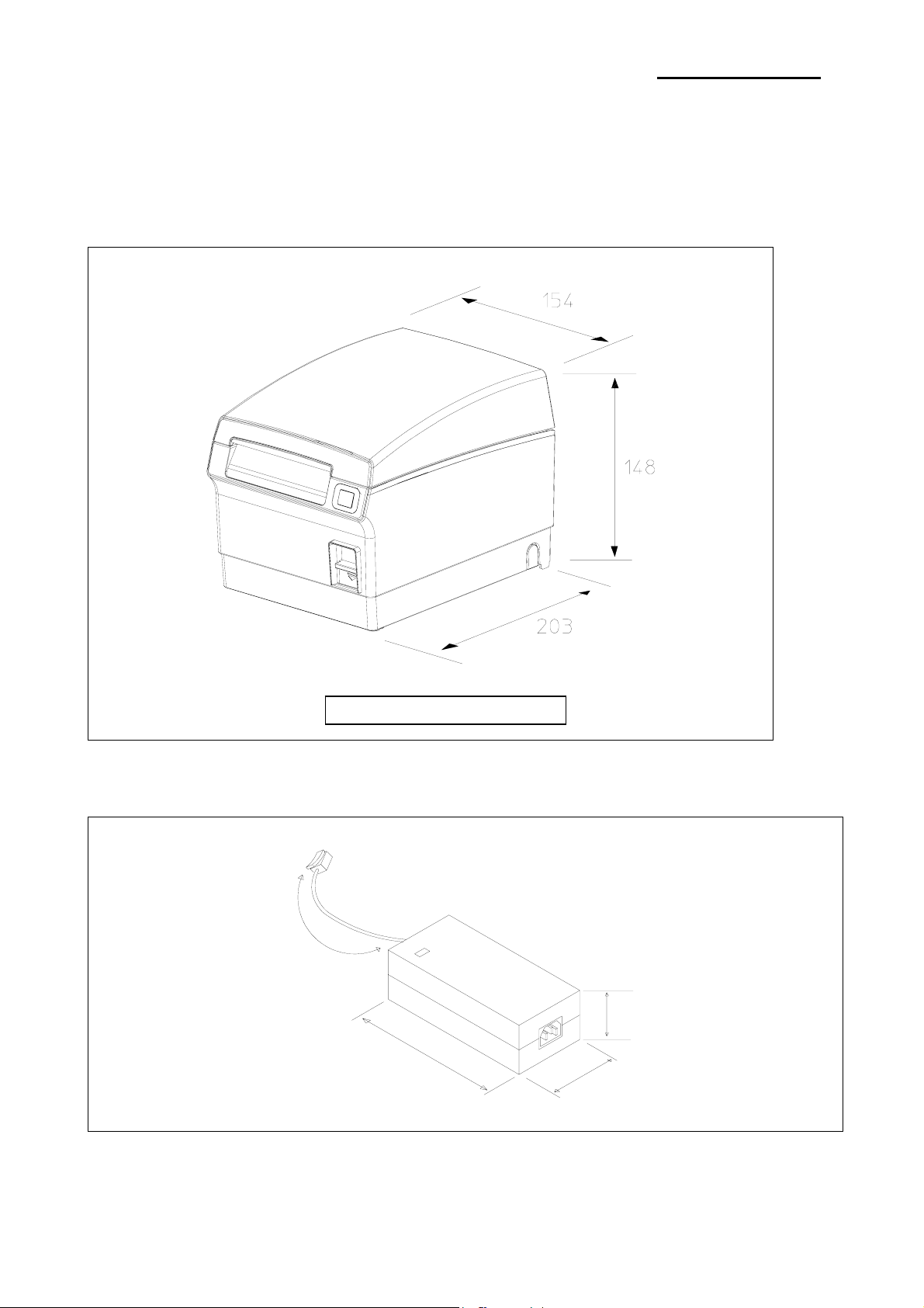
3-1-2 AC Adapter Dimensions (mm)
150mm
SRP-F310/312
Figure 3-1 Printer Dimension
120mm
Figure 3-2 Adapter Dimension
31mm
56mm
Rev. 1.00
- 15 -
Page 16
SRP-F310/312
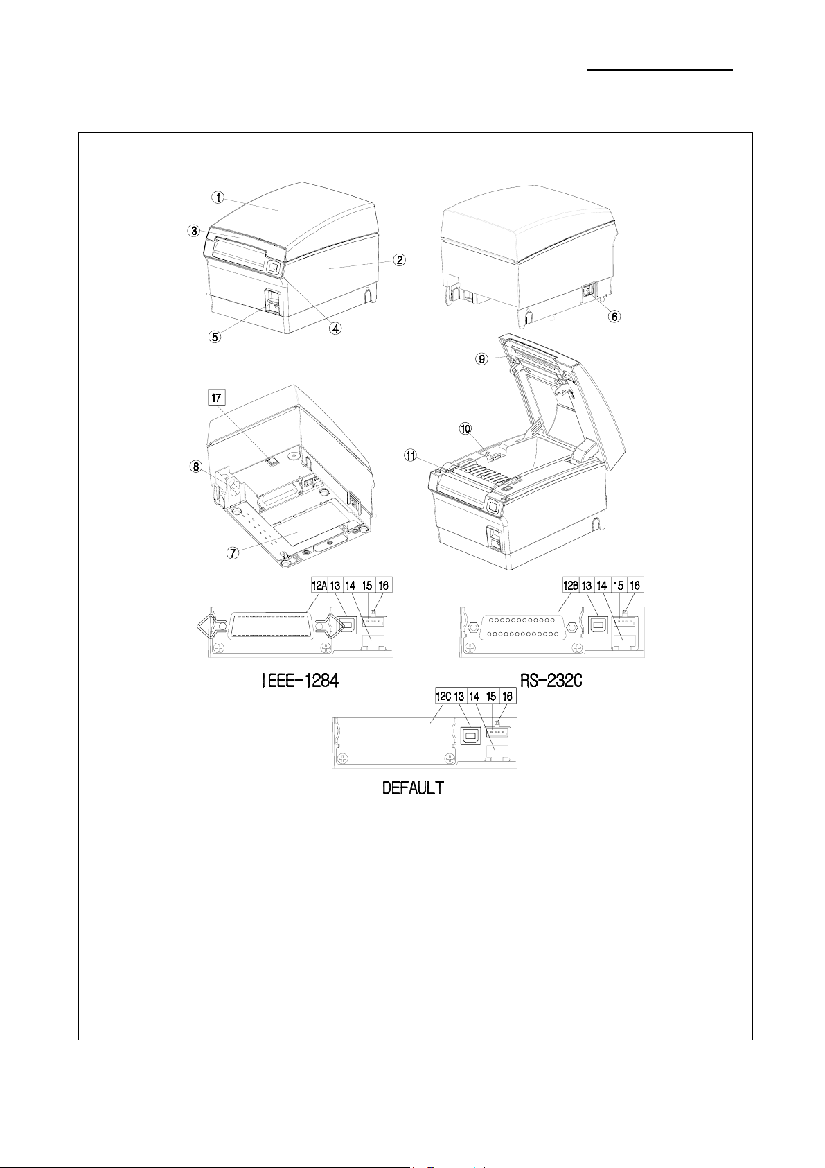
3-1-3 Feature Locations-SRP-F310/312
1. cover-open
2. case-lower
3. function-led
4. feed-button
5. Push Button
6. Power Button
7. cover Dip Switch
8. SMPS
9. TPH
Rev. 1.00
10. Paper Sensor Control
11. Auto-Cutter
12A. Parallel interface(IEEE-1284)
12B. Serial interface(RS-232C)
12C. Default interface
13. USB B-TYPE 2.0
14. ETHERNET
15. Dongle
16. ETHERNET, WLAN Reset
17. DK(RJ11)
Figure 3-3 Feature Location
- 16 -
Page 17

SRP-F310/312
3-2 General Specifications
Item Description Remark
• SRP-F310/312: Default Communication
Product
Processor
Memory
Interface Serial
(RS-232C)
Interface Parallel
USB
USB2.0
Printer
Auto Cutter
Power Consumption • Approx. 27W (Peak)
Electrical
Condition
AC
Adapter
(SMPS)
Dimensions(mm) • 203(W) x 154(D) x 148(H)
Environmen
t Condition
Weight • 3.1 Kg (With Packing)
• SRP-F310/312P: IEEE1284 Parallel Communication
• SRP-F310/312S: RS-232C Serial Communication
• ST SPEAR-09-B042(ARM926EJ-S core @ 333MHz)
Internal boot ROM Size: 32KBytes
Internal static RAM Size: 8KBytes
• RAM
DDR2 SDRAM: 256Mbits (MT47H16M16BG-3:G)
NAND FLASH: 128Mbits (NAND128W3A2CN6F)
• Flow Control:
1) DTR / DSR (H/W Flow Control)
2) XON / XOFF (S/W Flow Control)
• Baud Rate: 2400 / 4800 / 9600 / 19200 / 38400
/ 57600 / 115200 bps
• Receive Buffer: 4 Kbytes
• Connector: DB25P Female (I/F PBA Side)
• Mode:
1) Forward Mode: Compatibility Mode
2) Reverse Mode: Nibble / Byte Mode
• Connector: 36 Pin Centronics (Ribbon Type)
• Transfer Type: BULK
• Speed: 12 Mbps (Full-Speed)
• Power: Self-Powered
• Transfer Type: BULK
• Speed: 480 Mbps (High-Speed)
• Power: Self-Powered
• Printing Method: Thermal Line Printing
• Printing Speed
1) SRP-F310: Mono 270mm/Sec, 63.82 Line/Sec
2Color 130mm/Sec, 30.73Line/sec
2) SRP-F312: Mono 270mm/Sec, 72 Line/Sec
2Color 130mm/Sec, 34.6Line/sec
• Type: Guillotine
• Cutting Method: 1 Point Partial Cutting
• Input: AC 100V ~ 240V, 50Hz/60Hz
• Output: DC 24V±5%, 2.5A
Temperature
Humidity
Altitude
• Operating: 0°C ~ +45°C
• Storage: -20°C ~ +60°C
• Operating: 10% to 80%
non-condensing
• Storage: 10% to 90%
non-condensing
• Operating: 10,000ft(Max)
• Storage: 10,000ft(Max)
Table 3-1 General Specification
The Flow Control, Baud
Rate, Stop Bit and
Parity Are determined
by DIP S/W position.
Rev. 1.00
- 17 -
Page 18
SRP-F310/312
3-3 Thermal Printer Specifications
3-3-1 Printer Specification
1) 180dpi
Item Description Remark
Model • SRP-F310 (TPH: KRB-72-7TA02-BIX2,KYOCERA CORPORATION)
Print Method • Thermal Line Printing
Dot Density • 0.141 mm(7 Dots/mm)
Printing Direction • Unidirection with friction feed
Printing Width • 72.2mm, 512 dot Position
Character / Line • 42 (Font A: 12x24) • 56 (Font B: 9x17 )
Character Spacing
Printing Speed
Paper feeding Speed • Approx. 270mm/sec
2) 203 dpi
Item Description Remark
Model • SRP-F312 (TPH: KRC-80-8TA02-BIX2,KYOCERA CORPORATION)
Print Method • Thermal Line Printing
Dot Density • 0.125mm(8 Dots/mm)
Printing Direction • Uni-direction with friction feed
Printing Width •80.0mm, 640 dot Position
Character / Line • 48 (Font A: 12x24) • 64 (Font B: 9x17 )
Character Spacing
Printing Speed
Paper feeding Speed • Approx. 270mm/sec
3-3-2 Character Specification
Item Description Remark
Number of Character
Character Structure
• 0.28mm (0.01) (2 dots) (Font A)
• 0.28mm (0.01) (2 dots) (Font B)
• Mono Max. 270mm (63.82 Lines/sec, 1/6inch feed)
• 2color Max. 130mm (30.73 Lines/sec, 1/6inch feed)
• Ladder Barcode: Mono 270mm/sec, 2Color 130mm/sec
Table 3-2 Thermal Printer Specification
• 0.25mm (0.01) (2 dots) (Font A)
• 0.25mm (0.01) (2 dots) (Font B)
• Mono Max. 270mm (72 Lines/sec, 1/7inch feed)
• 2color Max. 130mm (34.6 Lines/sec, 1/7inch feed)
• Ladder Barcode: Mono 270mm/sec, 2Color 130mm/sec
Table 3-3 Thermal Printer Specification
• Alphanumeric Characters: 95
• Extended Characters: 128 x 34 Page
(Including one space page)
• International Characters: 32
• 12 x 24 (Font A) (Including 2-dot spacing in horizontal)
• 9 x 17 (Font B) (Including 2-dot spacing in horizontal)
Font A is selected as the default
Table 3-4 Thermal Printer Character Specification
Rev. 1.00
- 18 -
Page 19
SRP-F310/312
3-3-3 Paper Specification
Item Description Remark
Paper Type
Paper Form • Paper Roll
Paper Width • 80mm / 83mm
Paper Roll Size • Max 105mm(3.26”)
Spool Inside Dia. • 12mm (0.47)
Spool Outside Dia. • 18mm (0.71)
※ Note
* Mono: The Following paper can be used instead of the specified paper above.
TF50KS-E(Paper thickness: 65μm): Nippon Paper industries Co., Ltd.
PD 160R ( “ : 75μm): New Oji Paper Mfg, Co., Ltd.
P350 ( “ : 62μm): Kansaki Specialty Paper, Inc. (USA)
* 2Color: PB-670 ( “ : 75μm): Mitsubishi
PD750R ( “ : 75μm): Oji paper Mfg. Co.,Ltd.
• Mono:TF50KS-E(Nippon paper)
• 2Color: PB-70(Mitsubishi)
Table 3-5 Thermal Printer Paper Specification
3-3-4 Reliability and Environment Specification
Item Description Remark
• Mechanism: Monochrome: 20,000,000 Lines
2Color : 10,000,000 Lines
Life
MCBF • Monochrome:70,000,000Lines, 2Color:35,000,000Lines
Environmental
Temperature
Humidity
The reliability values above are assumed When a 15-Line feed
and a 10-Line print repeat alternately
• Head: 1x10
• Auto Cutter: 1,800,000 Cut,
• Operating: 0°C ~ +45°C
• Storage: -20°C ~ +60°C (Except for Paper)
• Operating: 10% ~ 80% RH(non-condensing)
• Storage: 10% ~ 90% RH(non-condensing)
Table 3-6 Thermal Printer Reliability Specification
8
Pulses, Monochrome: 150Km, 2Color: 75Km
Rev. 1.00
- 19 -
Page 20
SRP-F310/312
a
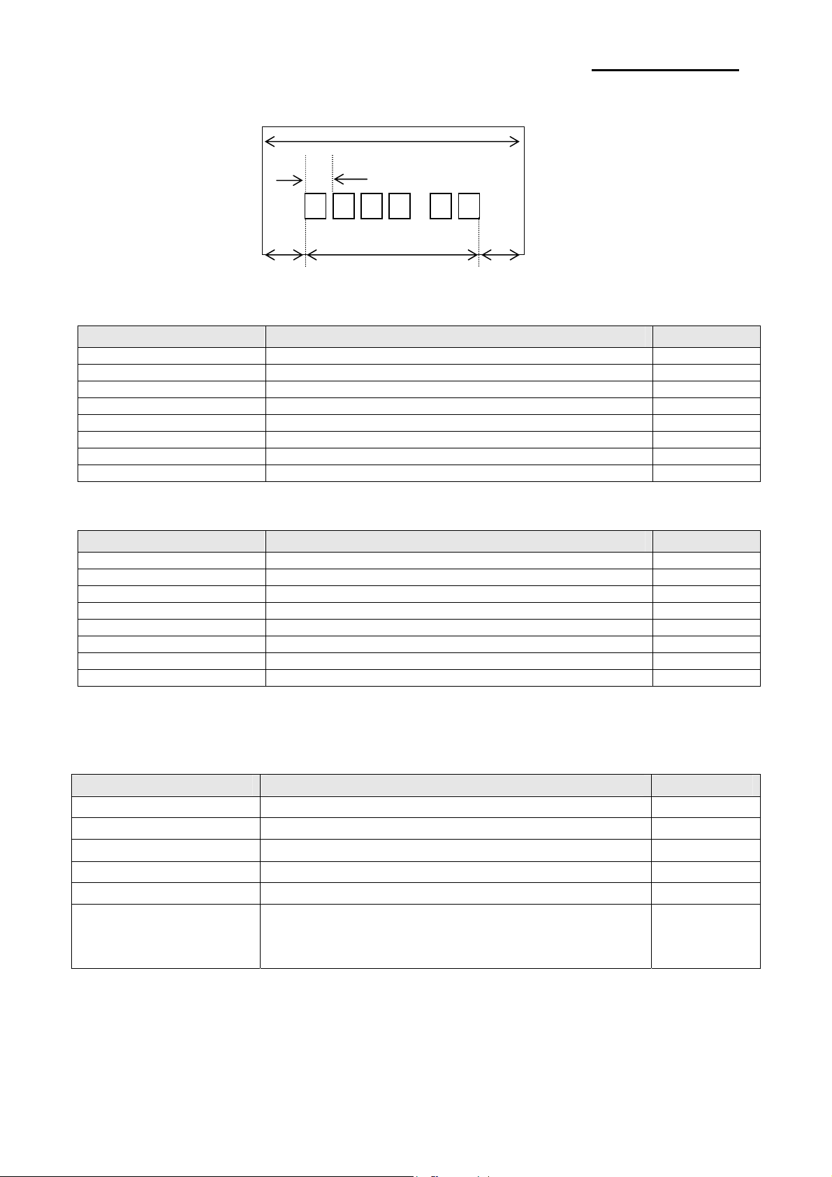
3-3-5 Printable Area
1) 180dpi
Item Description Remark
a 80±0.5mm(3.15 ±0.0197)
b 0.141 (0.0056 )
c 72.2±0.2mm(2.83 ±0.0079)
d 2.75mm~4.25mm
e 2.75mm~4.25mm
Dots 512
Font 9X17 56 Character
Font 12X24 42 Character
* ‘d’ & ‘e’ position can be shifted while printing according to the paper position.
2) 203dpi
Item Description Remark
A 80±0.5mm(3.15 ±0.0197)
B 0.125 (0.0049 )
C 80mm±0.2mm (2.83±0.0079)
D 2.75mm~4.25mm
E 2.75mm~4.25mm
Dots 640
Font 9X17 64 Character
Font 12X24 48 Character
* ‘d’ & ‘e’ position can be shifted while printing according to the paper position.
d c e
b
Figure 3-4 Printable Area
3-3-6 TPH (Thermal Printer Head) Specification
1) 180dpi
Item Description Remark
Heat Element Structure 2 Heaters / Dot
Number of Heat Element 512 Dots
Heat Element Pitch 0.141mm/dot, 7Dot/mm (180DPI)
Print Width 72.2±0.2mm
Average Resistance 800Ω ± 3%
Thermister
1) Resistance R25: 30kΩ ± 5% (At 25℃)
2) B Value: 3950K ± 2%
3) Temperature: - 40℃ ~ +80℃
Table 3-7 TPH Specification
Rev. 1.00
- 20 -
Page 21
SRP-F310/312
Item Maximum Unit Conditions
Print Cycle (S.L.T.) 0.46 ms/Line
T=25℃
Supply Energy 0.20 mJ/Dot
Supply Voltage 24 V Voltage among the connector terminals
Substrate Temperature 70
℃
Temperature detected by Thermistor
Number of heating dots at same time 256 Dots
Logic Supply Voltage (VDD) 3.3 V
Logic Supply Current (IDD) 204 mA ALL-HIGH
Table 3-8 TPH Maximum Condition (At 25℃)
2) 203dpi
Item Description Remark
Heat Element Structure 2 Heaters / Dot
Number of Heat Element 640 Dots
Heat Element Pitch 0.125mm/dot, 8Dot/mm (203DPI)
Print Width 80±0.2mm
Average Resistance 800Ω ± 3%
Thermister
1) Resistance R25: 30kΩ ± 5% (At 25℃)
2) B Value: 3950K ± 2%
3) Temperature: - 40℃ ~ +80℃
Table 3-9 TPH Specification
Item Maximum Unit Conditions
Print Cycle (S.L.T.) 0.42 ml/Line
Supply Energy 0.09 mJ/Dot
T=25℃
Supply Voltage 24 V Voltage among the connector terminals
Substrate Temperature 70 ℃ Temperature detected by Thermistor
Number of heating dots at same time 320 Dots
Logic Supply Voltage (VDD) 3.3 V
Logic Supply Current (IDD) 255 mA ALL-HIGH
Table 3-10 TPH Maximum Condition (At 25℃)
3-3-7 Other Component Specification
Item Description Remark
• Model: ORC-RWB80 (OHYANE RIKI MFG, Co., Ltd)
• Type: Guillotine Type
Auto Cutter
• Motor: DC Brush Motor FK-180SH-12280 (Mabuchi Motor)
• Voltage: 24V DC ± 5%(Motor), 5V DC ± 5%(Switch)
• Current: 200mA (Average), 1.5A(Peak)
• Model: STH-39H0001 (SHINANO MOTOR CO, LTD.)
• Type: 2-Phase, Bi-Polar chopper dual,3.75 Step angle
Paper Feed Motor
• Voltage: 4.13V ± 10% DC
• Drive Current: 0.7A [PHASE]
• Winding Resistance: 5.9Ω ±10% @ 25℃
• Winding Inductance: 4.2mH ±20% @ 1KHz 1Vrms
Paper End Sensor • Reflection Type Photo Sensor
Paper Roll Near End Sensor • Reflection Type Photo Sensor
Table 3-11 Other Component Specification
Rev. 1.00
- 21 -
Page 22

3-4 SMPS Specifications
3-4-1 SMPS (Switching Mode Power Supply) Specification
Item Description Remark
• Typical: 100V ~ 240V AC
Input Voltage
Input Current • Max: 1.5A (When 120V)
Inrush Current Limiting
Load Regulation
Ripple Noise • ±200mV @ 24Vdc
Short-Circuit Protection
O.V.P
(Over Voltage Protection)
O.T.P
(Over-temperature Protection)
3-4-2 SMPS Output Connector
• Min: 90V AC
• Max: 264V ac
• Max: 30A at 115Vac input Voltage for a cold start at 25℃
ambient conditions
• +24V ±5% @ 0~2.5A Static
• +24V +5/-10% @ 2~6.5A Dynamic
• The power supply shall not be damaged from the condition that
between DC output and DC ground are shorted. An output short
circuit is defined as output impedance of less than 300mΩ for
greater than 1 second. The power supply will operate normally
when this condition is removed promptly within 2 seconds.
• 26Vdc~30Vdc
• The power supply will be shutdown at an over-temperature
condition. This shutdown shall be cleared by removal of this
abnormal condition and input power recycling.
Table 3-12 Power Adapter (SMPS) Specification
Pin Number Signal Name
1 +24 VDC
2 GND
3 N.C
Shield Frame GND
Table 3-13 Power Connector Pin Description
SRP-F310/312
Rev. 1.00
(a)
Figure 3-5 SMPS DC Output Connector(a) & Printer Power Connector(b)
(b)
- 22 -
Page 23

SRP-F310/312
3-5 Interface Specifications
3-5-1 RS-232C Serial Interface
3-5-1(a) Specification
Item Description Remark
Data Transmission • Serial
Synchronization • Asynchronous
HandShaking
(Flow Control)
Signal Level
Baud Rate • 2400/4800/9600/19200/38400/57600/115200 bps
Data Word Length • 8 bits
Parity • None
Connector • DB25P Female (I/F PBA)
※ Note: The HandShaking (Flow Control) / Data Word Length / Baud Rate / Parity functions depend on the
DIP Switch settings. Refer to the Operation Manual.
3-5-1(b) RS-232C I/F Cable
• H/W: DTR/DSR
• S/W: XON/XOFF
• Logic1 (MARK): -3V ~ -15V
• Logic0 (SPACE): +3V ~ +15V
Table 3-14 RS-232C Specification
XON: ASC Code 11h
XOFF:ASC Code 13h
Connector: User Spec.
In Case PC: D-SUB25P-Female or D-SUB9P-Female
Figure 3-6 RS-232C Cable
Printer Side: D-SUB25P-Male
Rev. 1.00
- 23 -
Page 24

3-5-1(c) Cable Connection
SRP-F310/312
PRINTER
SIDE (25P)
3-5-1(d) Signal Description
Pin No. Signal name Direction Function
1 FG - Frame Ground
2 TxD Output Transmit Data
3 RxD Input Receive Data
4 RTS Output Ready To Send
5 CTS Input Clear To Send
6 DSR Input
7 SG -
20 DTR Output
HOST
SIDE (25P)
Figure 3-7 RS-232C Cable Connection
This signal indicates whether the host computer can receive data.
(H/W flow control)
1) MARK(Logic1): The host can receive a data.
2) SPACE(Logic0): The host can not receive a data.
3) The printer transmits a data to the host, after confirming
this signal.
4) When XON/XOFF flow control is selected, the printer does
not check this signal.
Signal Ground
This signal indicates whether the printer is busy. (H/W flow control)
1) MARK(Logic1): The printer is busy.
2) SPACE(Logic0): The printer is not busy.
3) The host transmits a data to the printer, after confirming
this signal.
4) When XON/XOFF flow control is selected, the host does
not check this signal.
Table 3-15 RS-232C Pin Description
PRINTER
SIDE (25P)
HOST
SIDE (9P)
Rev. 1.00
- 24 -
Page 25

SRP-F310/312
3-5-1(e) H/W Flow Control
When DTR/DSR flow control is select, before transmitting a data, the Printer checks whether the host is
BUSY or not. If the host is BUSY, the Printer does not transmit a data to the host. If the host is not BUSY, the
Printer transmits a data to the Host. The host is the same. Refer to the Interface Part of Chapter 7 (Special
Circuit Diagrams).
3-5-1(f) S/W Flow Control
When XON/XOFF flow control is selected, the printer transmits XON(ACSII 11h) or XOFF(ASCII 13h) signal
through the TXD line.
If the Printer is BUSY, the Printer transmits XOFF(ASCII 13h) to host through the TXD line. Then the host
recognize that the Printer is BUSY. So, the host does not transmit a data to the Printer. If the Printer is
released from BUSY, the Printer transmits XON(ASCII 11h) to host through the TXD line. Then the host
recognize that the Printer is not BUSY. And the host transmit a data to the Printer.
※ Note: Refer to the Operation Manual about XON/XOFF flow control.
3-5-2 IEEE1284 Parallel Interface
Bidirectional parallel interface: in accordance with the IEEE1284 Nibble/Byte mode.
3-5-2(a) Forward Mode Specification (Compatibility mode)
Data transmission from host computer to printer: Centronics compatible
Item Description Remark
Data Transmission • 8-bits Parallel
Synchronization • External supplied nStrobe signals
HandShaking • nACK and Busy signals
Signal Level • TTL compatible
Connector • Centronics 36P
Table 3-16 IEEE1284 Specification
3-5-2(b) Reverse Mode Specification (Nibble / Byte mode)
Data transmission from the printer to the host computer.
The STATUS data transmission from the printer to the host computer is accomplished in the Nibble or Byte
mode. This mode allows data transmission from the asynchronous printer under the control of the host
computer. Data transmission in the Nibble mode are made via the existing control lines in units of for bits
(Nibble). In the Byte mode, data transmission in accomplished by making the 8-bit data lines bidirectional.
Neither mode can operate at the same time as the compatibility mode, so switching is always required.
Rev. 1.00
- 25 -
Page 26
SRP-F310/312
3-5-2(c) Signal Specification (Compatibility/Nibble/Byte mode)
Pin No. Source Compatibility Mode Nibble Mode Byte Mode
1 Host nStrobe HostClk HostClk
2 Host / Printer Data 0 (LSB) - Data 0 (LSB)
3 Host / Printer Data 1 - Data 1
4 Host / Printer Data 2 - Data 2
5 Host / Printer Data 3 - Data 3
6 Host / Printer Data 4 - Data 4
7 Host / Printer Data 5 - Data 5
8 Host / Printer Data 6 - Data 6
9 Host / Printer Data 7 (MSB) - Data 7 (MSB)
10 Printer nAck PtrClk PtrClk
11 Printer Busy PtrBusy/Data3,7 PtrBusy
12 Printer Perror AckDataReq /Data2,6 AckDataReq
13 Printer Select Xflag/Data1,5 Xflag
14 Host nAutoFeed HostBusy HostBusy
15 NC ND ND
16 GND GND GND
17 FG FG FG
18 Printer Logic-H Logic-H Logic-H
19~30 GND GND GND
31 Host nlnit nInit nlnit
32 Printer nFault nDataAvail /Data0,4 nDataAvail
33 GND ND ND
34 Printer DK_Status ND ND
35 Printer +5V ND ND
36 Host nSelectln 1284-Active 1284-Active
Table 3-17 IEEE1284 Pin Description
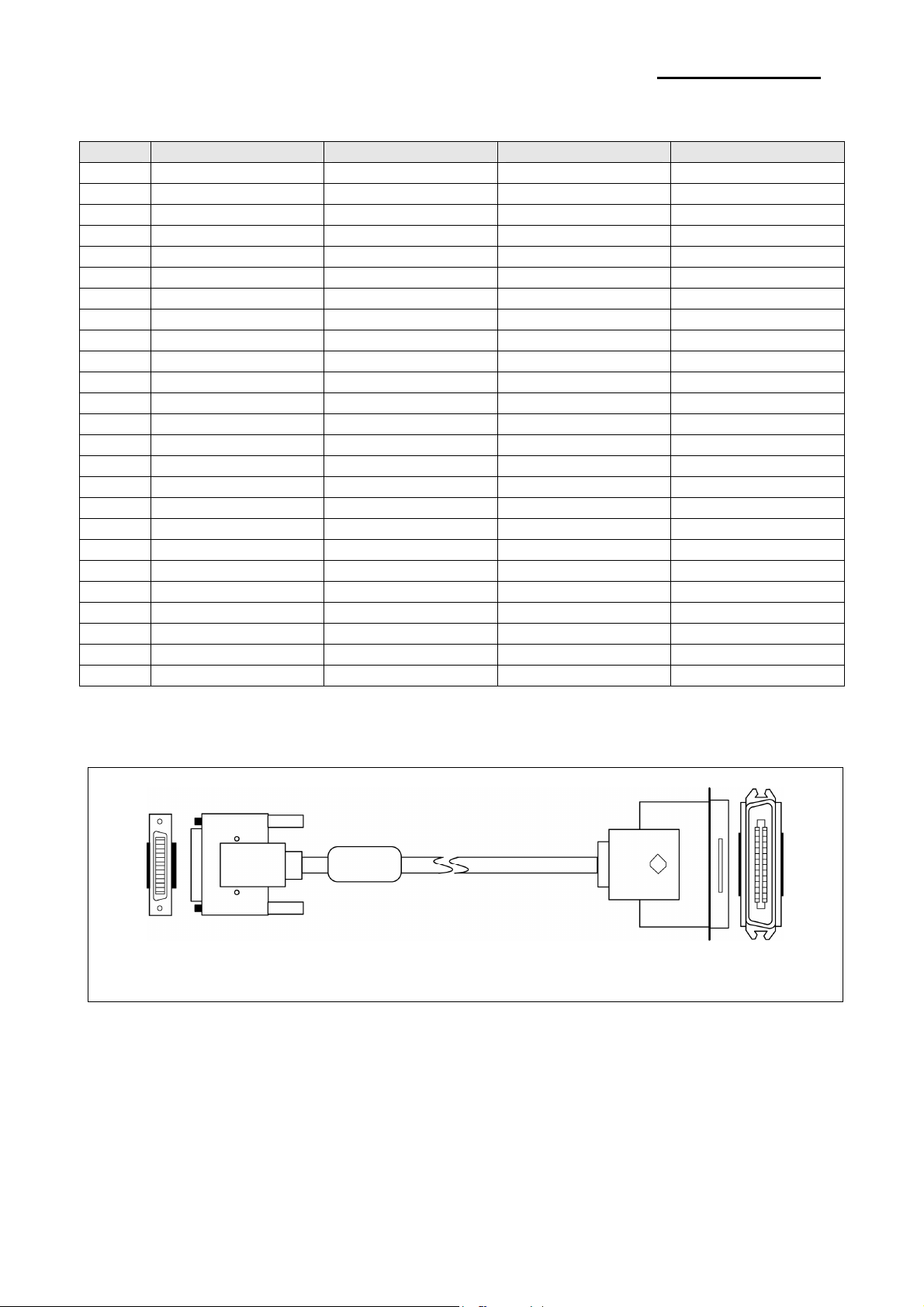
3-5-2(c) IEEE1284 I/F Cable
Rev. 1.00
Host Side: DB25M
Printer Side: CN36M
Figure 3-8 IEEE1284 Cable
- 26 -
Page 27
SRP-F310/312
3-5-3 USB2.0 Interface
SRP-F310/312 support the USB (Universal Serial Bus) Serial Communication.
3-5-3(a) Specification
Item Description Remark
Transfer Type • BULK
Data Signal
Data Format
Speed • 480 Mbps
Cable & Connector
Other
3-5-3(b) Signal Description
Pin No. Signal Name Assignment(Color) Function
Shell Shield Drain Wire Frame Ground
1 VBUS Red Host Power: DC5[V] / 500[mA]
2 D- White Differential Data Line
3 D+ Green Differential Data Line
4 GND Black Signal Ground
3-5-3(c) Cable
USB cable consists of four conductors, two power conductors, and two signal conductors.
High-/full-speed cable consists of a signaling twisted pair, VBUS, GND, and an overall shield. High-/full
speed cable must be marked to indicate suitability for USB usage. High-/full-speed cable may be used with
either low-speed, full-speed, or high-speed devices. When high-/full-speed cable used with low-speed
devices, the cable must meet all low-speed requirements.
Low-speed recommends, but does not require the use of a cable with twisted signaling conductors.
• Bi-direction, Half-Duplex
• Differential Signal Pair (D+ / D-)
• NRZI Format
• Zero Bit Stuffing after 6 ones
• Cable: 5m / 2m
• Connector: B Type(Device) / A Type(Host)
• Supports the 480 Mbps high-speed mode (HS) for
USB 2.0, as well as the 12 Mbps full-speed (FS) and
the low-speed (LS modes) for USB 1.1
Table 3-18 USB Specification
Table 3-19 USB Pin Description
Rev. 1.00
- 27 -
Page 28

SRP-F310/312
Figure 3-9 USB Cable
3-5-4(d) Construction
Raw materials used in the fabrication of this cable must be of such quality that the fabricated cable is
capable of meeting or exceeding the mechanical and electrical performance criteria of the most current USB
Specification revision and all applicable domestic and international safety/testing agency requirements; e.g.,
UL, CSA, BSA, NEC, etc., for electronic signaling and power distribution cables in its category.
American Wire
Gauge (AWG)
28
26
24
22
20
Nominal Conductor
Outer Diameter
0.381 mm (0.015)
0.406 mm (0.016)
0.483 mm (0.019)
0.508 mm (0.020)
0.610 mm (0.024)
0.610 mm (0.024)
0.762 mm (0.030)
0.787 mm (0.031)
0.890 mm (0.035)
0.931 mm (0.037)
Table 3-20 Power Pair
Stranded Tinned
Conductors
7 x 36
19 x 40
7 x 34
19 x 38
7 x 32
19 x 36
7 x 30
19 x 34
7 x 28
19 x 32
Rev. 1.00
- 28 -
Page 29

SRP-F310/312
※ Note: Minimum conductor construction must be stranded tinned copper.
To minimize end user termination problems, USB uses a keyed connector protocol. The physical difference
in the Series A and B connectors insures proper end user connectivity. The A connector is the principle
means of connecting USB devices directly to a host or to the downstream port of a hub. All USB devices
must have the standard Series A connector specified in this chapter. The B connector allows device vendors
to provide a standard detachable cable. This facilitates end user cable replacement.
Figure 2-10 illustrates the keyed connector protocol.
Series A Connectors
Series B Connectors
◆Series A plugs are
always oriented upstream
towards the Host System
A Plugs
(From the
USB Device)
A Receptacles
(Downstream Output
from the USB Host orHub)
Figure 3-10 Keyed Connector Protocol
The following list explains how the plugs and receptacles can be mated:
• Series “A” receptacle mates with a Series “A” plug. Electrically, Series “A” receptacles function as outputs
from host systems and/or hubs.
• Series “A” plug mates with a Series “A” receptacle. The Series “A” plug always is oriented towards the host
system.
• Series “B” receptacle mates with a Series “B” plug (male). Electrically, Series “B” receptacles function as
inputs to hubs or devices.
• Series “B” plug mates with a Series “B” receptacle. The Series “B” plug is always oriented towards the USB
hub or device.
◆Series B plugs are
always oriented downstream towards
the USB Device
B Plugs
(From the
Host System)
B Receptacles
(Upstream Input to the
USB Device or Hub)
Rev. 1.00
- 29 -
Page 30

SRP-F310/312
3-6 Cash Drawer Specifications
3-6-1 Drawer Cable
Ferrite Core: 1 turn (OP-18E: 18.2 x 12.5 x 25.5)
Figure 3-11 Drawer Cable
3-6-2 Cable Connection
Pin No. Description Direction
1 Frame GND 2 Drawer Kick-Out Driver Signal #1 Output
3 Drawer Open / Close Signal Input
4 +24V 5 Drawer Kick-Out Driver Signal #2 Output
6 Signal GND -
Table 3-21 Drawer Cable Connection
※ Note: +24V is always output through pin 4 during power on.
Rev. 1.00
- 30 -
Page 31
SRP-F310/312
3-7 ETHERNET Specifications
3-7-1 Ethernet
1) Ethernet specifications
Network Interface: 10/100 Base-T All in one type (Auto detection)
[Protocol]
Layer Protocol
Network Layers ARP, IP, ICMP
Transport Layers TCP, UDP
Application Layers
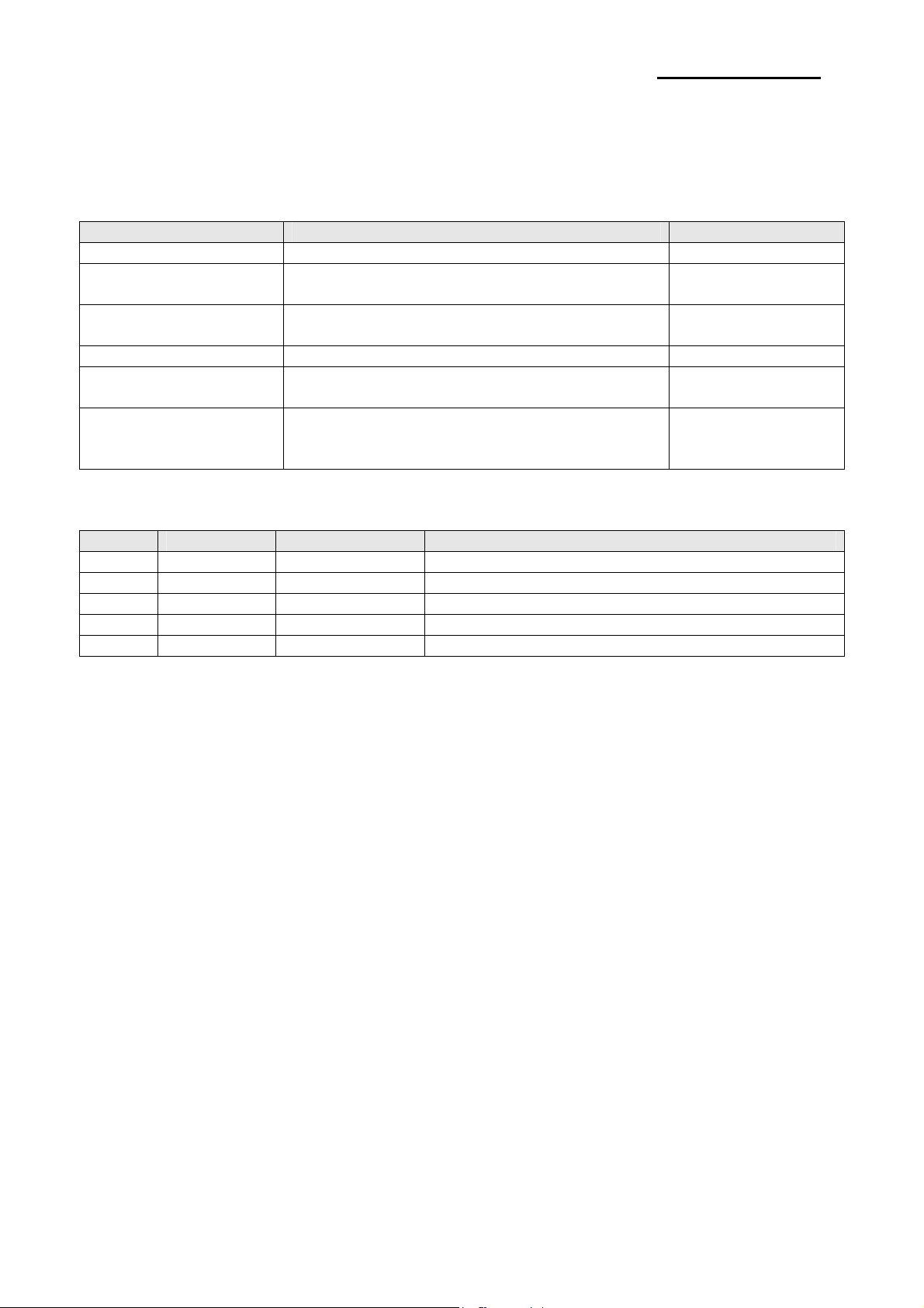
2) Ethernet cable
3) Ethernet signal descriptions
Pin No. Signal name Assignment (Color) Function
1 TD+ White Orange Transmit +
2 TD- Orange Transmit 3 TCT White Green Receive +
4 NC Blue
5 NC White Blue
6 RCT Green Receive 7 RD+ White Brown
8 RD- Brown
* For more information, refer to the Network User Manual in Bixolon Web Site.
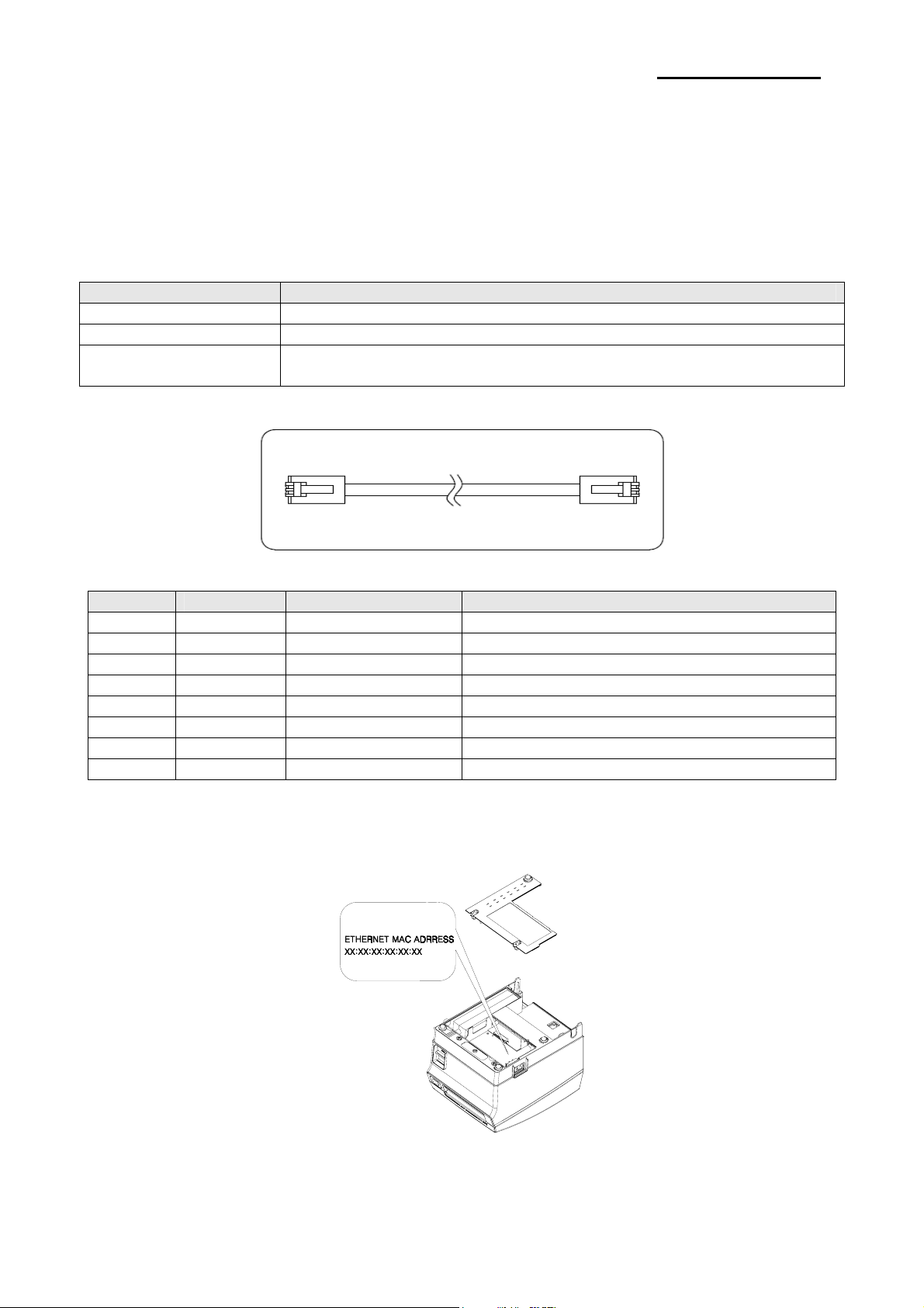
4) Ethernet MAC address
When you open the cover, you can see the 'ethernet MAC address' on the board.
DHCP, DNS, Raw Print, SMTP(notify Printer status)
HTTP, HTTPS(setting), FTP (settings), TELNET (settings)
Rev. 1.00
- 31 -
Page 32
SRP-F310/312
3-7-2 WLAN
1) WLAN specifications
Support IEEE 802.11b/g Infrastructure, Ad-hoc mode.
Frequency Band and Operating Channels]
Item Description
Frequency band 2.4000 – 2.497 GHz
Modulation OFDM with BPSK, QPSK, 16QAM, 64QAM (11g) BPSK, QPSK, CCK (11b)
Data rate : 54/48/36/24/18/12/11/9/6/5.5/2/1 Mbps auto fallback
[Protocol]
Layer Protocol
Network Layers ARP, IP, ICMP
Transport Layers TCP, UDP
Application Layers
[Security]
- WEP64/128
- WPA/WPA2(TKIP/AES-CCMP) PSK
- HTTPS(SSL2.0, SSL3.0, TLS1.0)
2) WLAN USB extension cable
DHCP, DNS, Raw Print, SMTP(notify Printer status)
HTTP, HTTPS(settings), FTP (settings), TELNET (settings)
3) Compatible WLAN USB adaptor list
SRP-F310/312 is compatible with WLAN USB adaptor using RT73(RT2571W/RT2573/RT2671) chipset.
You can use WLAN printer with WLAN USB adaptor offered by BIXOLON Co.,Ltd. or purchased by
personally.
Tested WLAN USB adaptor list is below.
- CNET CWD-854
- TP-Link TL-WN32G
- D-Link DWA-110
- Buffalo WLI-U2-SG54HP
We recommand using WLAN USB adaptor in a list.
* For more information, refer to the Network User Manual in BIXOLON Co.,Ltd. Web Site.
Rev. 1.00
- 32 -
Page 33

SRP-F310/312
4. Hardware
4-1 Wiring Diagram
Rev. 1.00
[Figure 4-1 Board Wiring Diagram]
- 33 -
Page 34
SRP-F310/312
4-2 Block Diagram
Rev. 1.00
- 34 -
Page 35
SRP-F310/312
Rev. 1.00
- 35 -
Page 36

SRP-F310/312
Rev. 1.00
- 36 -
Page 37

SRP-F310/312
Rev. 1.00
- 37 -
Page 38

SRP-F310/312
[Figure 4-2 Block Diagram]
Rev. 1.00
- 38 -
Page 39
SRP-F310/312
4-3 Special Circuit Descriptions
4-3-1 Power Circuit
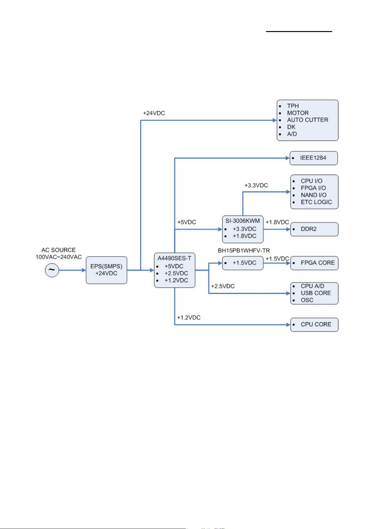
This system is operated under 100Vac or 240Vac. The power circuit supplies the three differential DC voltage
sources.
[Figure 4-3 Power Block Diagram]
1) Drawer Driving and Feed, Auto Cutter Motor Voltage and TPH Driving Voltage: +24VDC
+24VDC is supplied from SMPS. This Voltage is smoothed by capacitors (CE1).
This voltage is used as a Cash Drawer Solenoid Driving voltage, Step motor driving voltage and a source
voltage of the other voltage sources and TPH Driving Voltage.
2) IEEE1284 Logic IC Driving Voltage: +5VDC
Step down voltage the input +24VDC to +5VDC by a switching regulation U13(A4490SES-T)
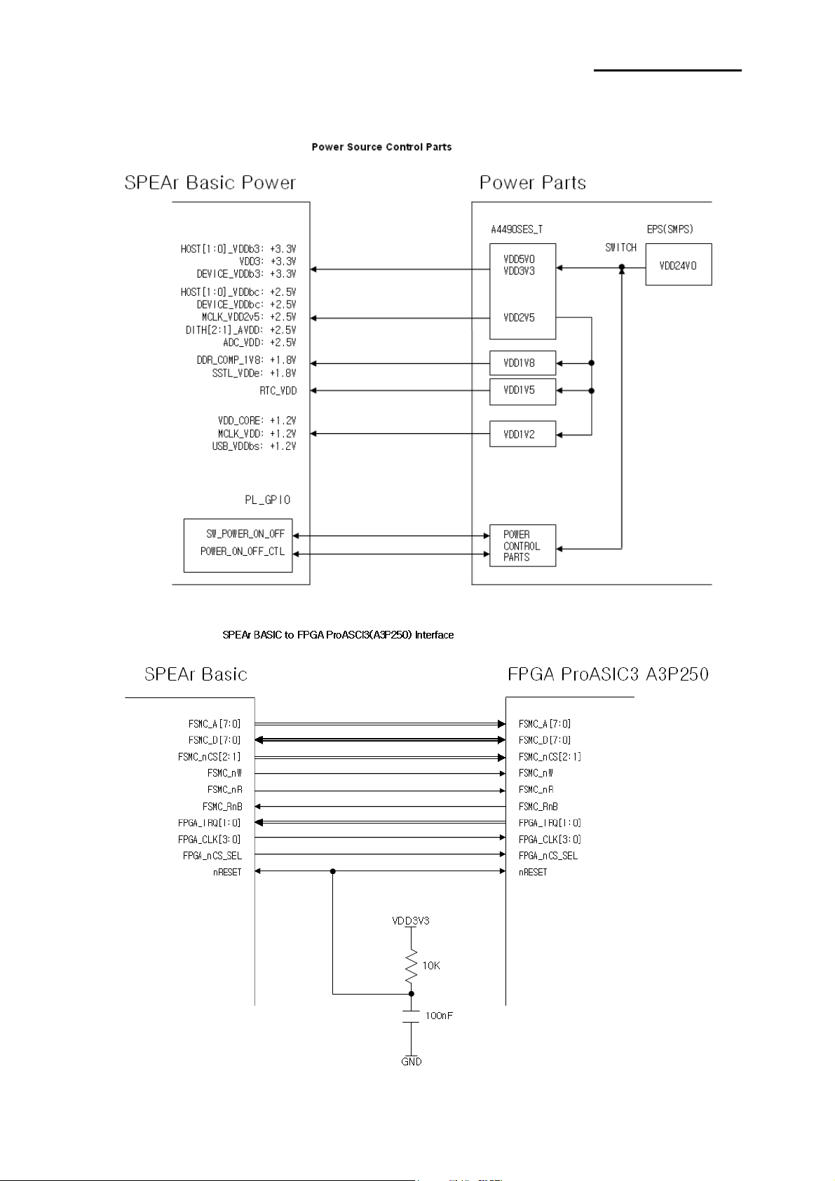
3) CPU I/O, FPGA I/O, NAND Flash and etc. LOGIC Voltage: +3.3VDC
Step down voltage the input +5VDC to +3.3VDC by a regulation.U15(SI-3006KWM)
4) CPU A/D, USB core and OSC Voltage: +2.5VDC
Step down voltage the input +24VDC to +2.5VDC by a switching regulation.U13(A4490SES-T)
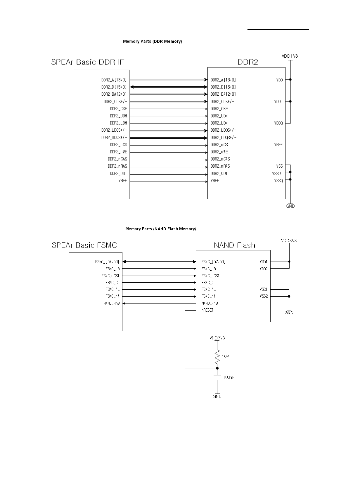
5) DDR2 Voltage: +1.8VDC
Step down voltage the input +5VDC to +1.8VDC by a regulation.U15(SI-3006KWM)
Rev. 1.00
- 39 -
Page 40
SRP-F310/312
6) FPGA core Voltage: +1.5VDC
Step down voltage the input +2.5VDC to +1.5VDC by a regulation.U16(BH15PB1WHFV-TR)
7) CPU core Voltage: +1.2VDC
Step down voltage the input +24VDC to +1.2VDC by a switching regulation.U13(A4490SES-T)
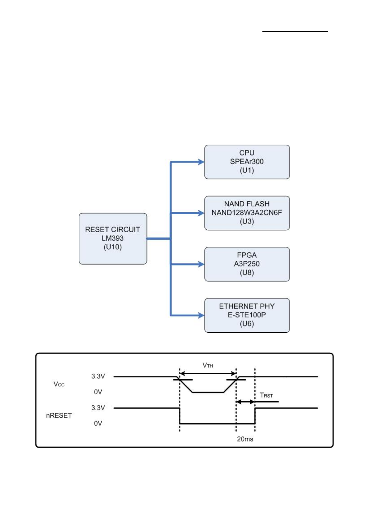
4-3-2 RESET Circuit
Reset signal is signal in order to start-up CPU under Power-on.
Reset circuit uses a reset ASM811REUSF-T(U8). When 3.3Vdc is fallen under 2.7Vdc by Power-off,
reset signal prohibits the system from miss-operating by lowering down to 0V.
Rev. 1.00
[Figure 4-4 Reset Block Diagram]
[Figure 4-5 Reset Waveform]
- 40 -
Page 41
SRP-F310/312
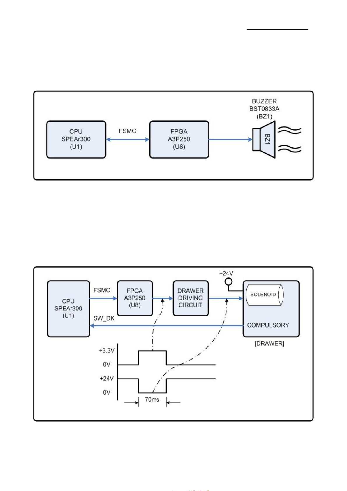
4-3-3 Buzzer and Cash Drawer Circuits
1) Buzzer Driving Circuit
The Buzzer is used to inform several kinds of states which occur under system operating and gives some
information to users by controlling the CPU (SPEAr300)
[Figure 4-6 Buzzer Block Diagram]
2) Cash Drawer Driving Circuit
The circuit is used for opening cash drawer and driven by the Q301, Q302(2SD2170). When its state is high
level signal, Q301 or Q302 (2SD2170) drive the solenoid to open the cash drawer. As an optional item, we
provide sensor switch (we call it a compulsory switch) which checks the drawer whether it is opened or not.
This sensor switch turns on for the drawer open condition, and turns off for the other.
※ Caution: Make sure that the Cash Drawer solenoid resistance is more than 20Ω.
Rev. 1.00
[Figure 4-7 Cash Drawer Block Diagram]
- 41 -
Page 42

SRP-F310/312
4-3-4 I/F PBA Detect Block Diagram
When the printer is ON, the printer checks what kind of the I/F PBA is installed. After detection, the CPU
specify the I/O port properly. The following is the method of I/F PBA detection.
The I/F PBA has the three return Signal (MD0~2).
The CPU recognize the I/F PBA by the value of the three return signal.
I/F PBA MD0 MD1 MD2
RS-232C L H L
IEEE1284 H L L
No Connection L L L
4-3-5 RS-232C Communication Block Diagram
The CPU is used for serial communication. And also RS-232C Driver (MAX232), is used to serial
communication. Show following block diagram.
[Figure 4-8 RS-232C Communication Block Diagram]
Rev. 1.00
[Figure 4-9 RS-232C Communication Waveform]
- 42 -
Page 43
SRP-F310/312
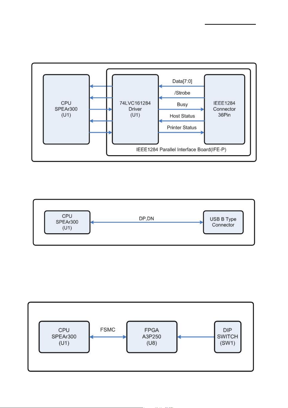
4-3-6 Parallel Communication Block Diagram
The printer support the bidirectional Parallel Interface with Centronics, Nibble, Byte Mode.
The Centronics is Forward and the Nibble, Byte are reverse Mode.
[Figure 4-10 IEEE1284 Communication Block Diagram]
4-3-7 USB Communication Block Diagram
The printer support the USB (Universal Serial Bus). The transfer type of the printer is the BULK.
[Figure 4-11 USB2.0 Communication Block Diagram]
4-3-8 DIP Switch Circuit
The key board circuit consist of the scan signal of 3 lines and the return signal of 2-line. The CPU sends
repeatedly and continuously the scan data DIP_A~DIP. The DIP S/W information input in the return signal if
the specific DIP S/W is ON status during the given time. The CPU reads the data through DIP IN1~IN2 and
analyzes what DIP S/W is ON and performs the selected function.
[Figure 4-12 USB Communication Block Diagram]
Rev. 1.00
- 43 -
Page 44

SRP-F310/312
4-3-9 Thermal Printer Head Circuit
First, the CPU sends a Serial Clock and Serial Data 256bits(32Bytes) to the Shift Register of the Thermal
Printer. The Serial Data are stored to each Shift Register in the Thermal Printer. Because the Data#1 Pin and
the Data#2 pin are shorted on Main PCB, the Data(256bits) are stored in both Shift Register#1 and #2.
Second, the CPU send a Latch Signal to the Thermal Printer. Then, the Data of both Shift Register#1 and #2
(256*2=512bits) are moved to the Latch Register. After that, the CPU sends a Strobe Signal to the Thermal
Printer. Then, the Printer outputs the Serial Data. Each Strobe Signal manages the Printer Dot.
STB No. DOT No. DOTs/STB SRP-F310/312 Strobe Processing
STB1 1 ~ 256 256
STB2 257 ~ 512 256
The content of data is same.
CPU
SPEAr300
CLK
DATA#1,2
[Figure 4-13 Thermal Printer Block Diagram]
256 CLK
256bits 256bits 256bits
/LATCH
STROBE1
STROBE2
Rev. 1.00
Printing (1~256 ) P rinting(1~256)
Printing( 257~512)
[Figure 4-14 Thermal Printer Timing Waveform]
- 44 -
Page 45

5. Disassembly and Assembly
5-1 Case lower block
SRP-F310/312
1. Remove the ①two screws.
2. Separate the ②COVER DOWN-FRONT
1. Remove the ①two screws.
2. Separate the ②INTERFACE DEFAULT
Rev. 1.00
- 45 -
Page 46

SRP-F310/312
1. Separate the ①COVER DIP-SWITCH
form the SRP-F310/312
2. Remove the ②SMPS
1. Remove the ①two screws.
2. Separate the ②ASE LOWER
Rev. 1.00
- 46 -
Page 47

SRP-F310/312
1. Separate the ①FPC from MAIN PCB
2. Separate the ②FIVE CONNECTOR
from MAIN PCB
1. Remove the ①four screws.
2. Separate the ②MAIN PCB
from ④BRACKET PCB.
3. Remove the ③two screw.
4. Separate the ④BRACKET PCB
from SRP-F310/312.
Rev. 1.00
- 47 -
Page 48
SRP-F310/312
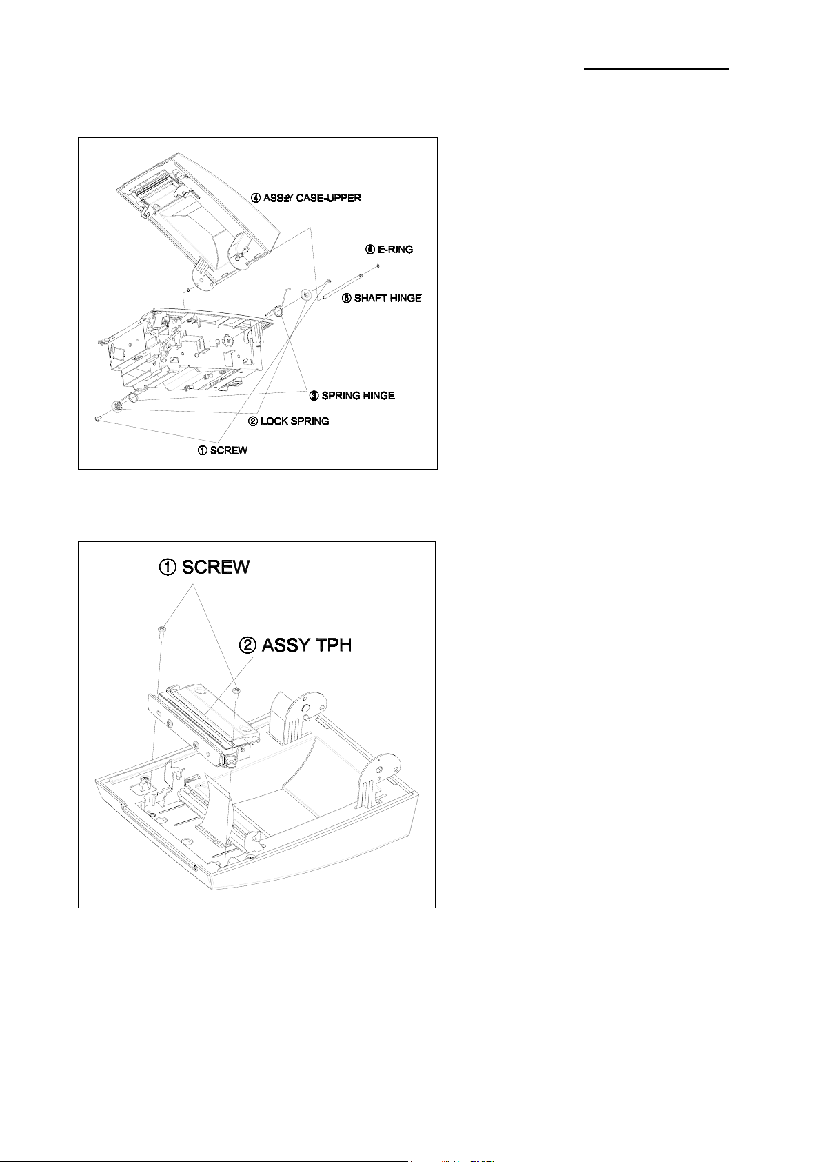
5-2 Case Upper block
1. Remove the ①screw
2. Separate the ②LOCK SPRING,
③SPRING HINGE
3. Remove the ⑥E-Ring.
4. Separate the ⑤SHAFT HINGE
From ④ASS`Y CASE-UPPER
1. Remove ①two screws.
2. Separate the ②ASS`Y TPH
From ASS`Y CASE-UPPER
Rev. 1.00
- 48 -
Page 49

SRP-F310/312
1. Remove the ①two screws.
2. Separate the ②CASE UPPER
from the ASSY HOUSING.
3. Separate the ③COVER UP-FRONT
from ②CASE UPPER
4. Remove the ④screw.
5. Separate the ⑤COVER HINGE
from the ASSY HOUSING.
1. Remove the ①four screws.
2. Separate the ②BRACKET HOUSING
from the ASSY HOUSING
3. Separate the ⑥two WASHER
from the ⑤SHAFT HINGE
4. Separate the ⑤SHAFT HINGE and
③BRACKET HOOK and ④SPRING
from the ②BRACKET HOUSING
5. Remove the ⑧screw.
6. Separate the ⑨PCB LED
from the ⑦COVER HOUSING
7. Remove the ⑫⑬FFC,FPC
from the ⑪PCB TPH
8. Remove the ⑩two screws.
9. Separate the ⑪PCB TPH
from the ⑦COVER HOUSING
Rev. 1.00
- 49 -
Page 50

SRP-F310/312
1. Remove the ①two screws.
2. Separate the ②GUIDE TPH
from the ASSY TPH
3. Remove the ⑥screw.
4. Separate the ASSY FIXED CUTTER
from the ASSY TPH
5. Remove the ③two screws.
6. Separate the ④CUTTER
from the ⑤GUIDE CUTTER
7. Remove the ⑫SPECIAL SCREW.
8. Separate the ⑪E-RING, ⑩SHAFT TPH
from the ⑦TPH
9. Remove the ⑧SPRING TPH, ⑦TPH
from the ⑨BRACKET TPH
Rev. 1.00
- 50 -
Page 51

5-3 Frame block
SRP-F310/312
1. Remove the ①two screws.
2. Separate the ASSY CUTTER
from the FRAME MAIN
3. Remove the ③four screws.
4. Separate the ④AUTO CUTTER
from the ②BRACKET CUTTER
1. Separate the ①PARTITION
from the FRAME MAIN
2. Remover the ③WASHER.
3. Separate the ②SHAFT FEED
from the FRAME MAIN
4. Remover the ④WASHER.
5. Separate the ⑤PUSH BUTTON
And ⑥SPRING LOCK-L
from the FRAME MAIN
Rev. 1.00
- 51 -
Page 52

SRP-F310/312
1. Remove the ①four screws.
2. Separate the ②BRACKET MAIN
From the FRAME MAIN
3. Remove the ③screw.
4. Separate the ④COVER OPEN S/W
From the FRAME MAIN
5. Remove the ⑤screw.
6. Separate the ⑥PCB FEED
From the FRAME MAIN
7. Remove the ⑦screw.
8. Separate the ⑧PCB PAPER-END
From the FRAME MAIN
Rev. 1.00
1. Remove the ①screw, And separate
the NEAR END SENSOR from
the BRACKET MAIN.\
2. Remover the ⑥SCREW.
3. Separate the ③KNOB P-END and
④HOUSING SENSOR from the
②HOUSING P-END
4. Separate the ⑤PCB SENSOR
from the ④HOUSING SENSOR
5. Remover the ⑧E-RING
6. Separate the ⑦two GEARS
from the BRACKET MAIN
7. Remove the ⑨two SCREWS
8. Separate the ⑩MOTOR
from the BRACKET MAIN
9. Remove the ⑪SCREW.
10. Separate the ⑫ PCB-DK
from the BRACKET MAIN
11. Remover the⑬ WASHER
12. Separate the ⑭SHAFT FIX
13. Remover the ⑮WASHER
14. Separate the ASSY ROLLER
PLATEN from the BRACKET MAIN
15. Remover the BUSHING
17. Remover the GEAR PLATEN
- 52 -
Page 53

SRP-F310/312
6. Adjustments and Maintenance
6-1 Adjustment
6-1-1 Remaining Roll Paper Adjustment
This sensor is set to the step4 position at the factory. If you find that there is not or too enough paper
remaining on the roll when the near-end sensor is triggered, you can change the setting to the upper or
Lower position as described below.
Note: The factory setting is based on a paper roll core with an outside diameter of 18mm. If you use a paper
roll with a core with an outside diameter of more than 18mm, it is better to change to the upper
position(Rotate the tab at front side) as described below.
1. Open the paper roll cover.
2. Rotate the tab at front or rear Position.
Rev. 1.00
- 53 -
Page 54

SRP-F310/312
6-2 Maintenance
Paper dust in the heating elements may lower the print quality.
In this case, clean the print head as follow;
Caution: ※ Turn off the printer power before cleaning.
Caution: ※ Note that the thermal head (Thermal element and Radiation plate) becomes very hot during
normal operation, creating the danger of burn injury. Be sure to wait for about 10 minutes after
turning printer power off before beginning the cleaning.
1. Open the cover-open.
2. Clean the thermal element (the area that looks like it is marked a thin black line) of the thermal head
with a cotton swab moistened with an alcohol solvent. (ethanol, methanol, or IPA)
3. After confirming that the alcohol solvent has been dried up completely, close the cover open.
Radiation plate
Head tip
Spring pin
Print circuit board
Connector
Note: ※ Never touch the thermal element with your hand.
Doing so can damage the thermal element.
Note: ※ Do not scratch the printer head.
Base
Heat sensitive
layer
Protective
layer
Electrode
Resistor
Board
Rev. 1.00
- 54 -
Page 55
SRP-F310/312
7. Troubleshooting
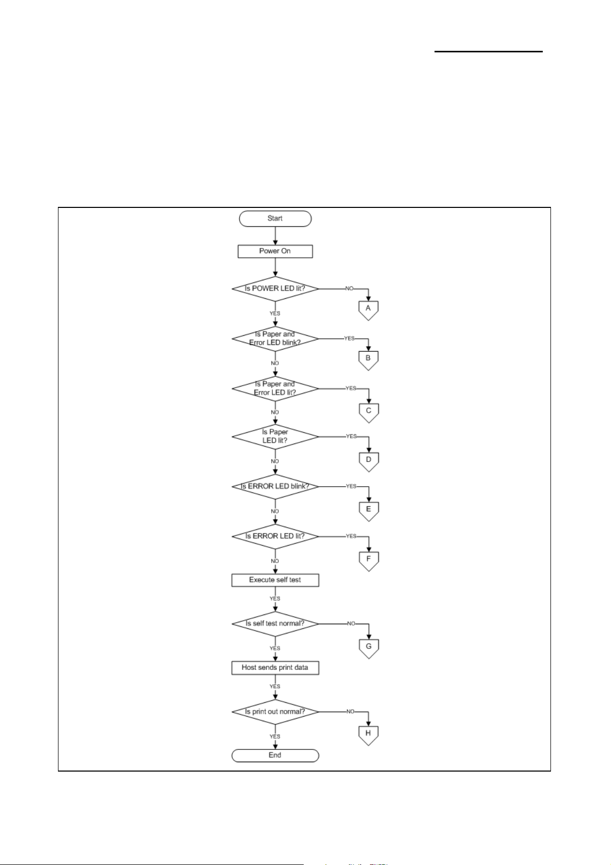
This chapter describes the methods for troubleshooting in this Receipt Printer.
7-1 Troubleshooting flow chart
If the source of a problem is not clear, use the flowchart below to find and replace a defective component.
Normally, servicing should be performed by component replacement. Repairs of the PCBs and other
components should be performed only by technicians.
Rev. 1.00
- 55 -
Page 56

SRP-F310/312
7-1-1 POWER LED does not light
A
Is AC adaptor & power cord
connected properly?
YES
Does AC adaptor have
proper output voltage rating?
(approx. +24V)
NO
NO
Connect AC adaptor & power cord
properly.
OK?
YES
END
NO
Replace AC adaptor.
YES
Has fuse F1 on
main PCB blown?
NO
Is POWER LED
continuity normal?
YES
Replace PCB-main ass’y
END
NO
NO
NO
OK?
YES
END
YES
Replace fuse F1
OK?
YES
END
NO
Replace Operation panel ass’y
OK?
YES
END
Rev. 1.00
- 56 -
Page 57

SRP-F310/312
7-1-2 Paper and Error led blink
Rev. 1.00
- 57 -
Page 58
SRP-F310/312
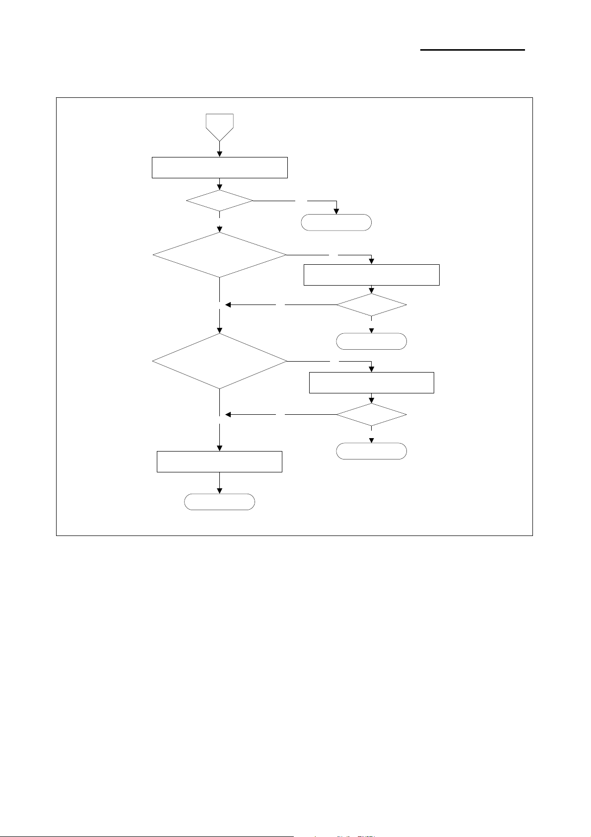
7-1-3 Paper and Error led lit
Turn power off, then once again
Is paper roll not inserted?
C
OK?
NO
YES
Is paper-end sensor,
continuity normal?
NO
YES
END
NO
Replace or insert paper roll
OK?
YES
END
NO
Replace Sensor-paper-end ass’y
YES
Replace PCB-main ass’y
END
NO
OK?
YES
END
Rev. 1.00
- 58 -
Page 59
SRP-F310/312
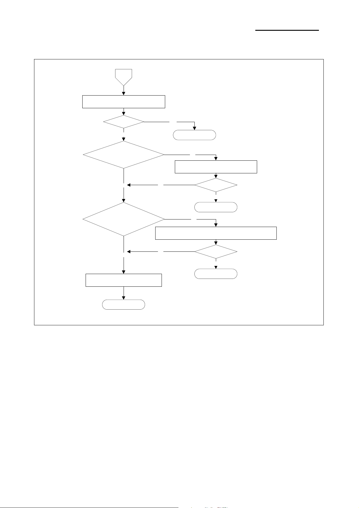
7-1-4 Paper led lit
D
Turn power off, then once again
OK?
NO
Is paper roll in
paper near-end condition?
YES
Is paper near-end sensor
continuity normal?
NO
YES
END
NO
Replace or insert paper roll
NO
OK?
YES
END
YES
Replace PCB-main ass’y
END
Replace Sensor-paper-near end ass’y
NO
OK?
YES
END
Rev. 1.00
- 59 -
Page 60

SRP-F310/312
7-1-5 Error led blink
E
Turn power off, then once again
OK?
NO
Is correct I/F PBA inserted?
YES
Replace PCB-main ass’y
NO
YES
END
NO
Replace I/F PBA
OK?
YES
END
END
Rev. 1.00
- 60 -
Page 61

SRP-F310/312
7-1-6 Error led lit
Rev. 1.00
- 61 -
Page 62
SRP-F310/312
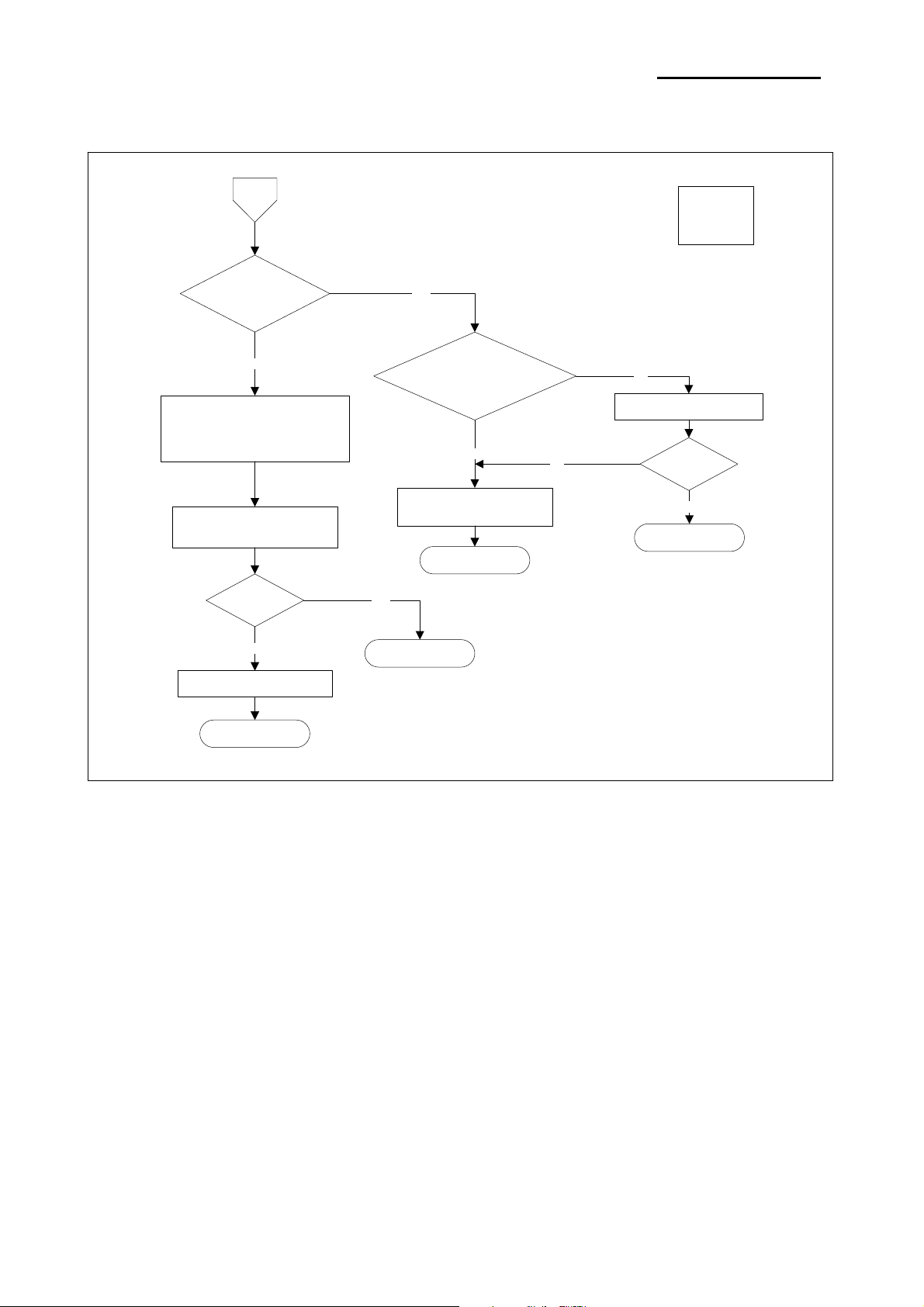
7-1-7 Self test is not normal
G
Does not printer
operate at all?
NO
Printing is carried out,
but print quality is deficient or
paper feeding is not normal
Replace printer
mechanism ass’y
YES
Is output voltage of
regulator on PCB-main
within SPEC?(*1)
YES
Replace printer
mechanism ass’y
END
NO
*1
VH : +24V
VCC : +5V
NO
Replace PCB-main ass’y
OK?
YES
END
OK?
NO
Replace PCB-main ass’y
END
YES
END
Rev. 1.00
- 62 -
Page 63
SRP-F310/312
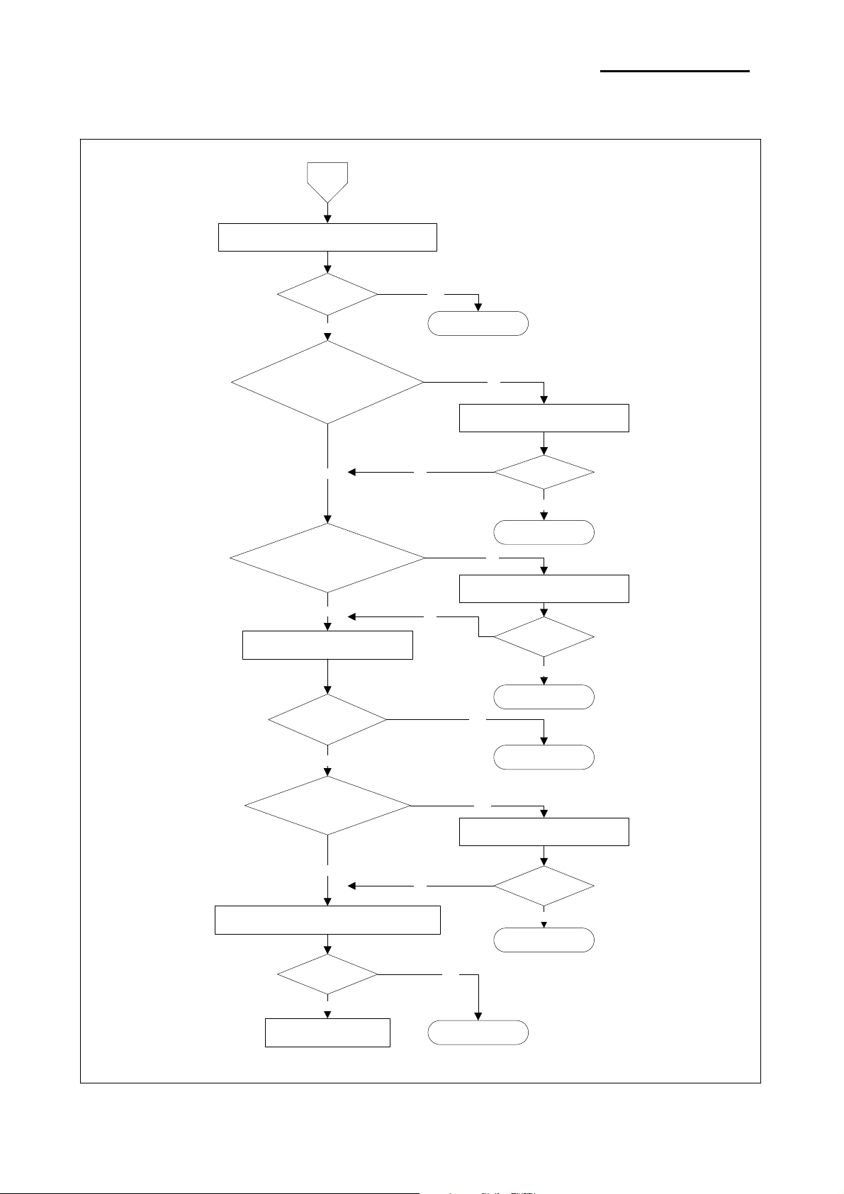
7-1-8 Data from host is not printed normally
H
Send data from host to printer
OK?
NO
Are interface
parameters set to
identical values at host and
printer?
YES
NO
YES
END
NO
Make settings identical
OK?
Does interface cable
match specifications?
YES
Replace interface PCB ass’y
OK?
NO
Is the interface
wire broken?
NO
NO
YES
END
NO
Replace with a proper cable
NO
OK?
YES
END
YES
END
YES
Replace the interface cable
OK?
Rev. 1.00
Replace printer mechanism ass’y
OK?
NO
YES
END
YES
ENDCheck the host
- 63 -
Page 64

SRP-F310/312
7-2 Power Problem
If a problem that can be verified by visual examination has occurred, use the tables below to determine the
cause and perform repairs.
There are four tables, divided by symptom category:
• Printing Quality Problems
• Printer Mechanism Problems
• Auto cutter Mechanism Problems
The tables contains the following columns:
• Problem
This is the symptom that can be verified
• Problem Causes
This is a listing of one or several possible causes that should be examined.
• Level
- Level A
The problem can be corrected by persons who are familiar with the printer and have general knowledge,
but special technical skills are not required.
- Level B
The problem requires thorough knowledge and familiarity with the printer as well as technical skills and
experience.
• Checkpoint
These are one or more areas in the printer that should be checked.
• Action
These are the steps to correct the problem. If the problem persists after taking these steps, check the
other possible causes listed.
Rev. 1.00
- 64 -
Page 65

SRP-F310/312
7-2-1 Printing Quality Problems
Problem Probable Cause Level Checkpoint Action
Certain parts
are printed
with vertical
white lines
Certain parts
are printed
with vertical
black lines
Horizontal
black lines
are
generated or
the vertical
width of the
characters is
reduced
Foreign substance on the
head surface
Head surface is damaged B
Internal IC of the head is
damaged
Vertical scratched trace on the
paper
Damage to the internal IC of
the head
Irregular feeding B
Feeding motor failure B
Roller rotation is not smooth A
Roller and the head are not
attached properly
A
B
A
B
A
Check the foreign
substance on the head
surface
Check the damage of the
head surface such as dents
Damage of the internal IC
of the head
Check whether there are
obstructions such as
bumps
Damage of the internal IC
of the head
Check for damage to the
gears and for foreign
substances in the gear
profile
Check whether the motor
runs smoothly without load
Check whether oil remains
in the bearings holding the
roller
Cover is not completely
closed
Remove the foreign
substance with a
cleaning pen
Replace the head
Replace the head
Remove the
obstructions
Replace the head
Replace the gears
or remove the
foreign substance
Replace the motor
Add oil for the
bearings
Open the cover,
then and
completely close it
Overall
printing
density is low
Rev. 1.00
The spring pushing the head is
not strong enough
Head surface is damaged B
B
- 65 -
Check whether the screws
mounting the spring are
loose
Check for abrasions on the
head surface
Fasten the screws
Replace the head
Page 66
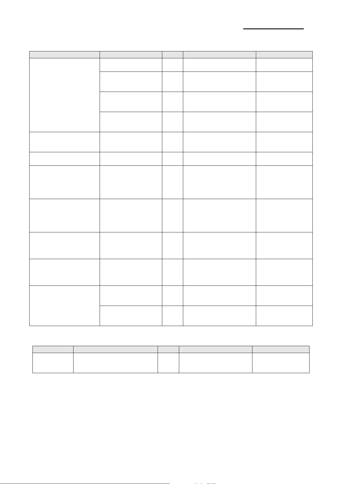
SRP-F310/312
7-2-2 Printer Mechanism Problems
Problem Probable Cause Level Checkpoint Action
Feeding motor failure B
Gear is dislocated
from the rotating axis
Paper feeding failure
Paper jam o B Check for paper jam
Auto cutter jam B Check for auto cutter jam
Cover cannot be
opened when pressing
the button
Cover cannot be
closed
Error LED is on and
there is a long and
continuous beep sound
while the printer is in
the ready state.
Error LED is on and
there is a short and
continuous beep sound
while the printer is in
the ready state.
Error LED is on and
there is no beep sound
while the printer is in
the ready state.
Joint or bouncing
sound during feeding
operation
Entered characters
and printed characters
are different
7-2-3 Auto Cut Mechanism Problems
Problem Probable Cause Level Checkpoint Action
Auto cutter
does not
work at all
DIP switch setting failure A
Auto cutter jam B Check for auto cutter jam
Deformation of Hook B
Cover Open sensor
failure
Paper End sensor
failure
Near End sensor
failure
Gears are damaged
or are impeded by
foreign substances
Check the
communication speed
Communication cable
failure
B
B Check for sensor failure
B Check the sensor failure
B Check for sensor failure
B
A
A
Check for short failure
inside the motor
Check the assembly
status of the washers
holding the gears
Check for deformation of
Hook
Check for damage or
foreign substances on the
gears
Communication speed is
set by DP switches for
Serial Mode
Check RS-232C null
modem
Cable
Check whether DIP
switch 1-1 is ON
Replace the motor
Reassemble the
gears and washers
Open the cover,
and then remove
the jammed paper
Open the cover
cutter, and then
restart the printer
Open the cover
cutter, and then
restart the printer
Straighten the
Hook with =pliers
Replace the sensor
Replace the sensor
Replace the sensor
Replace the gears
or remove the
foreign substance
Check the DIP
Replace the cable
Change ON to OFF
Ass’y
Ass’y
Ass’y
switch setting
Rev. 1.00
- 66 -
 Loading...