

Page 1
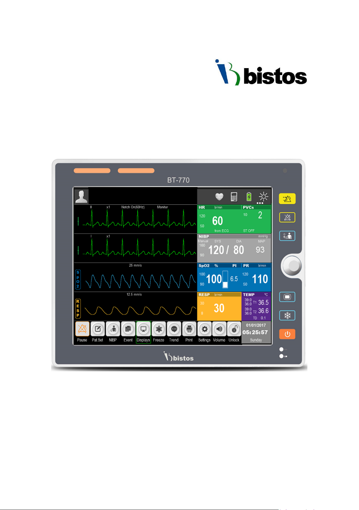
BT-770 Patient monitor
Operation Manual
Keep this manual for future reference
P/N : 770-ENG-OPM-EUR-R01
Page 2

BT-770 Operation manual
1
P/N : 770-ENG-OPM-EUR-R01
Bistos Co., Ltd.
2019.06
Information and descriptions contained in this manual are the property of Bistos Co., Ltd. and
may not be copied, reproduced, disseminated, or distributed without express written
permission from Bistos Co., Ltd.
Information furnished by Bistos Co., Ltd is believed to be accurate and reliable. However, no
responsibility is assumed by Bistos for its use, or any infringements of patents or other rights of
third parties that may result from its use. No license is granted by implication or otherwise
under any patent or patent rights of Bistos Co., Ltd.
The information contained herein is subjects to change without notice.
Prepared by:
Bistos Co., Ltd.
th
7
FL., A Bldg., Woolim Lions Valley 5-cha,
302, Galmachi-ro, Jungwon-gu, Seongnam-si,
Gyeonggi-do, Korea
Telephone: +82 31 750 0340
Fax: +82 31 750 0344
Revision R01
June, 2019
Printed in Korea
Copyright © Bistos Corporation 2018. All rights reserved.
Proprietary Material
Page 3

BT-770 Operation manual
2
P/N : 770-ENG-OPM-EUR-R01
Bistos Co., Ltd.
2019.06
Contents
0. Safety information ······················································································ 6
0.1 General precautions, warnings and cautions ···························································· 8
0.2 Shock hazards ············································································································· 11
0.3 Battery warnings········································································································· 12
0.4 General precautions on environment ······································································· 13
1. System basics ······························································································ 14
1.1 Intended use ··············································································································· 14
1.2 Operating principle ····································································································· 16
1.3 System configurations ································································································ 16
1.4 Product outlook ·········································································································· 18
1.5 Description of monitor ······························································································· 20
1.6 Understanding the display ························································································· 23
1.7 Smart Hotkeys ············································································································ 24
1.8 Essential performance ································································································ 24
2. Preparing for operation ··············································································· 25
2.1 Installation ·················································································································· 25
2.2 Connecting to power ·································································································· 27
3. Basic operations ·························································································· 28
3.1 Turn on ························································································································ 28
3.2 Turn off ······················································································································· 29
3.3 Basic operations ········································································································· 29
3.4 Operation mode ········································································································· 31
3.5 Measurement setup ··································································································· 32
3.6 Freezing waves ··········································································································· 32
3.7 Other common setup ································································································· 33
4. Patient information management ······························································· 36
4.1 Patient setup menu ···································································································· 36
4.2 Admitting a patient ···································································································· 37
4.3 Patient information ····································································································· 37
4.4 Discharging a patient ·································································································· 39
4.5 Clear alarms ················································································································ 39
4.6 Clear trend ·················································································································· 39
4.7 Clear NIBP trend ········································································································· 39
5. Display format ····························································································· 40
5.1 Selecting user interface ······························································································ 40
5.2 Display description ····································································································· 40
6. Alarm ············································································································ 43
6.1 Alarm types ················································································································· 43
6.2 Alarm condition priorities ·························································································· 43
6.3 Alarm mode ················································································································ 44
Page 4

BT-770 Operation manual
3
P/N : 770-ENG-OPM-EUR-R01
Bistos Co., Ltd.
2019.06
6.4 Alarm states ················································································································ 45
6.5 Alarm setup ················································································································· 48
6.6 Latch alarm ················································································································· 50
6.7 Manual event ············································································································· 51
6.8 Alarm record ·············································································································· 51
7. ECG ·············································································································· 52
7.1 Overview ····················································································································· 52
7.2 Safety information ····································································································· 52
7.3 Monitoring steps ········································································································ 53
7.4 ECG display ················································································································· 56
7.5 ECG setup ··················································································································· 57
7.6 Alarm setup ················································································································ 59
8. RESP ············································································································ 60
8.1 Overview ····················································································································· 60
8.2 Safety information ····································································································· 60
8.3 Placing electrodes for respiration monitoring ··························································· 60
8.4 Respiration display ····································································································· 61
8.5 Respiration setup ······································································································· 62
8.6 Alarm setup ····················································································································· 63
9. PR ················································································································ 64
9.1 Overview ····················································································································· 64
9.2 Display ························································································································ 64
9.3 Setting PR sound ········································································································· 64
9.4 Alarm setup ················································································································ 64
10. SpO2 ··········································································································· 65
10.1 Overview ··················································································································· 65
10.2 Safety information ··································································································· 65
10.3 Monitoring steps ······································································································ 66
10.4 Display ······················································································································ 67
10.5 Setting SpO
·············································································································· 67
2
10.6 Measuring influencing factors ·················································································· 68
10.7 Alarm setup ·············································································································· 69
10.8 Technical description ······························································································· 69
11. NIBP ··········································································································· 70
11.1 Overview ··················································································································· 70
11.2 Safety information ··································································································· 71
11.3 Measurement limits ································································································· 72
11.4 Measurement procedure ························································································· 73
11.5 NIBP display ·············································································································· 74
11.6 Setting inflation pressure ························································································· 75
11.7 NIBP reset ················································································································· 75
11.8 Clean and disinfection method of NIBP cuff ···························································· 75
11.9 Alarm setup ·············································································································· 76
Page 5

BT-770 Operation manual
4
P/N : 770-ENG-OPM-EUR-R01
Bistos Co., Ltd.
2019.06
12. TEMP ········································································································· 77
12.1 Overview ··················································································································· 77
12.2 Safety information ··································································································· 77
12.3 Measurement steps ································································································· 77
12.4 Measurement requirements ···················································································· 78
12.5 Temperature display ································································································ 78
12.6 Setting temperature unit ························································································· 79
12.7 Alarm setup ·············································································································· 79
13. Review ······································································································ 80
13.1 Reviewing trend chart ······························································································· 80
13.2 Reviewing trend table ······························································································ 81
13.3 NIBP measurement review ······················································································ 82
14. Battery ······································································································· 83
14.1 Overview ··················································································································· 83
14.2 Battery usage guide ·································································································· 83
14.3 Checking battery performance ················································································ 84
14.4 Battery recycling ······································································································· 84
15. Caring and cleaning ···················································································· 85
15.1 Overview ··················································································································· 85
15.2 Cleaning ···················································································································· 85
15.3 Disinfection ·············································································································· 86
16. Maintenance ······························································································ 87
16.1 Checking ··················································································································· 87
16.2 Viewing software version information ····································································· 88
16.3 Maintenance plan ···································································································· 88
16.4 ECG calibration ········································································································· 89
17. Accessories ································································································ 90
18. Specifications ····························································································· 191
18.1 Safety specification ·································································································· 91
18.2 Hardware specifications ··························································································· 92
18.3 Functional specification ··························································································· 93
19. Alarm information ······················································································ 98
19.1 Physiological alarm ··································································································· 98
19.2 Technical alarm ········································································································ 100
20. Default parameter configuration ································································ 102
21. Common faults and maintenance ······························································· 104
22. Manufacturer’s declaration on EMC ··························································· 105
22.1 Electromagnetic emissions ······················································································· 106
22.2 Recommended separation distances between portable and mobile RF communications
equipment and BT-770 ····································································································· 107
22.3 Electromagnetic immunity ······················································································· 108
Page 6

BT-770 Operation manual
5
P/N : 770-ENG-OPM-EUR-R01
Bistos Co., Ltd.
2019.06
Product Warranty ······························································································ 110
Figure 1-1: Front view ············································································································ 18
Figure 1-2: Side view ············································································································· 18
Figure 1-3: Rear view ············································································································· 19
Figure 1-4: Front view ············································································································ 20
Figure 1-5: Side view ············································································································· 21
Figure 1-6: Rear view ············································································································· 22
Figure 1-7: Standard display ·································································································· 23
Figure 3-1: “Settings” menu ·································································································· 31
Figure 4-1: “Patient” menu ··································································································· 36
Figure 4-2: “Quick Admit” menu ··························································································· 37
Figure 4-3: “Patient Info” menu ···························································································· 38
Figure 5-1: Standard display ··································································································· 40
Figure 5-2: Big ECG format ····································································································· 41
Figure 5-3: Big font format ···································································································· 42
Figure 5-4: ECG 7-Lead full screen format ············································································· 42
Figure 7-1: 3-Lead placement method ·················································································· 55
Figure 7-2: 5-Lead placement method ·················································································· 55
Figure 7-3: ECG wave in standard display format ·································································· 57
Figure 7-4: ECG parameter in standard display format ························································· 57
Figure 7-5: “ECG Setup” menu ······························································································
Figure 8-1: 5-lead respiration electrode placement ······························································ 61
Figure 8-2: Respiration wave ································································································· 61
Figure 8-3: Respiration parameter display ············································································ 62
Figure 8-4: “RESP setup” menu ····························································································· 62
Figure 9-1: PR parameter display ·························································································· 64
Figure 10-1: SpO
Figure 10-2: SpO
Figure 10-3: “SpO
parameter display ····················································································· 67
2
wave ········································································································· 67
2
Setup” menu ···························································································· 68
2
Figure 11-1: NIBP parameter display ····················································································· 74
Figure 12-1: TEMP parameter display ··················································································· 78
Figure 13-1: Trend chart ········································································································ 80
Figure 13-2: “Tr e nd” table ····································································································· 81
Figure 13-3: NIBP measurement review ················································································ 82
58
Page 7
BT-770 Operation manual
6
P/N : 770-ENG-OPM-EUR-R01
Bistos Co., Ltd.
2019.06
WARNING
CAUTION
Indicates the protection level against the ingress of liquid.
sensor
Indicates the protection level against the ingress of liquid.
It correspond the accessories for SpO2 and ECG.
0 Safety information
Before using BT-770 Patient monitor, read this entire manual and be fully understood the
following safety information to prevent injury of patient and user.
Symbols Used
The following symbols identify all instructions that are important to safety. Failure to follow
these instructions can lead to injury or damage to the patient monitor. When used in
conjunction with the following words, the symbols indicate:
Can lead to serious injury or death.
Can lead to minor injury or product/property damage
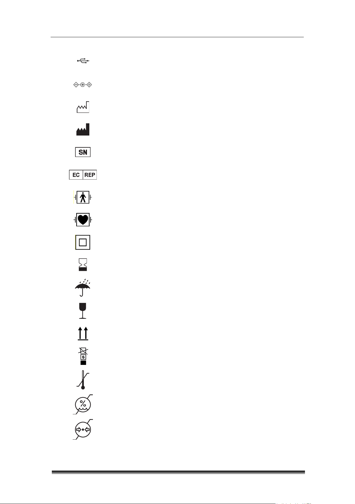
The following symbols are placed on product, label, packaging and this manual in order to
stand for the information about:
IPX1
IPX2
Used to identify safety information.
Be well-known this information thoroughly before using BT-770.
Used to identify safety information.
Be well-known this information thoroughly before using BT-770
IPX1 is protection against some water drops falling vertically.
It correspond the device, patient monitor and accessory, temperature
IPX2 is protection from some water drops when the device is tilted up
to and including 15°.
Refer to operation manual. Read manual before placing the device.
Indicates DC power supply.
Indicates the device is in the battery operation mode.
Indicates nurse call interface.
Indicates network interface.
Page 8
BT-770 Operation manual
7
P/N : 770-ENG-OPM-EUR-R01
Bistos Co., Ltd.
2019.06
Indicates the authorized representative in the European Community of
Indicates the medical device that can be broken or damaged if not
Indicates the temperature limitation for operation, transport and
Indicates the range of atmospheric pressure to which the medical
Indicates USB interface.
Indicates power adapter polarity.
Indicates the production date.
Indicates the manufacturer.
Indicates the serial number of the device.
manufacturer.
Indicates a defibrillation-proof type BF applied part.
Indicates a defibrillation-proof type CF applied part.
Indicates CLASS II equipment.(Adapter)
Indicates the date after which the medical device is not to be used.
Indicates to keep the device dry.
handled carefully.
Indicates to keep upright
Indicates the maximum stacking limit.
storage.
Indicates the humidity limitation for operation, transport and storage.
device can be safely exposed.
Page 9

BT-770 Operation manual
8
P/N : 770-ENG-OPM-EUR-R01
Bistos Co., Ltd.
2019.06
cates to not dispose the device together with unsorted municipal
Indicates the device contains natural rubber latex.(Accessories)
Indicates the packing material is recyclable.
Indi
waste(for EU only). The solid bar symbol indicates that mains adapter is
put on the market after 13 August 2005.
0.1 General precautions, warnings and cautions
• Examine the patient monitor and any accessories periodically to ensure that the
cables, adapter cords and instruments do not have visible evidence of damage that
may affect patient safety or performance. The recommended inspection interval is
once per week or less. Do not use the patient monitor if there is any visible sign of
damage.
• Only the DC power adapter supplied with the BT-770 is approved for use with the
device.
• Do not attempt to service the BT-770 patient monitor. Only qualified service
personnel by Bistos Co. Ltd. should attempt any needed internal servicing.
• Perform periodic safety testing to insure proper patient safety. This should include
leakage current measurement and insulation testing. The recommended testing
interval is once per year.
• If the hospital or healthcare institutions using this device fail to implement a
satisfactory maintenance schedule, it will result in device failure and may endanger
the patient’s safety.
• Use the patient monitor under the conditions specified in this operation manual.
Beyond the conditions, the patient monitor may not function properly and the
measurement results may not accurate and may result in device failure or
endangering the patient’s safety.
• Do not operate the BT-770 patient monitor if it fails to pass the power on self-test
procedure.
• During the operation, do not disconnect any cable.
• The BT-770 patient monitor is intended to be used by clinical professionals or trained
doctors, nurses or laboratory assistant.
• Do not service and maintain or clean the device including accessories while in use
with a patient.
Page 10

BT-770 Operation manual
9
P/N : 770-ENG-OPM-EUR-R01
Bistos Co., Ltd.
2019.06
WARNING
• Thoroughly read and understand the manual prior to use of the BT-770. Failure
needs to be installed and put into service according to the EMC information
• Using the device to one patient at a time.
to do so could result in personal injury or equipment damage.
• The device is intended for clinical patient monitoring, and only trained and
qualified doctors and nurses should use the device.
• The alarm volume, upper and lower alarm limits should be set according to the
actual situation of the using environment. Do not just rely on audio alarm
system while monitoring the patient, because too low alarm volume or muted
alarm may result in notice failure of alarm situation and endanger the patient’s
safety. Please pay close attention to the actual clinical status of the patient.
• Use only the power adapter supplied with monitor.
• Position the monitor where it is easy to de-energize the monitor when needed.
• Do not open the enclosure to avoid an electric shock. Any repair and upgrade
of monitor should be done by service personnel trained and authorized by
Bistos. Co., Ltd.
• When handling packaging materials, abide by local laws and regulations or
hospital waste disposal regulations. Keep the packaging materials away from
children.
• Do not use in the presence of flammable anesthetics to prevent explosion or
fire.
• Install the power lines and cables of accessories carefully to avoid patient
entanglement or suffocation, cables tangled or electrical interference.
• When the monitor is used together with electrosurgical devices, the user (a
doctor or a nurse) should ensure the safety of the patient and instrument.
• The physiological wave, physiological parameters and alarm information
displayed on the monitor are only for the doctor’s reference and should not be
directly used as the basis for clinical treatment.
• This is not a therapeutic device.
• For patients with pacemakers, the cardio tachometer may count the
pacemaker pulse in case of a cardiac arrest or arrhythmias. Never rely solely on
the cardio tachometer alarm. Closely monitor the patients with pacemaker. For
the inhibition of the device on pacemaker, refers to this manual.
• Use of accessories other than those listed and approved for use with this
product may result in increased emissions or decreased immunity.
• Medical electrical equipment needs special precautions regarding EMC and
Page 11

BT-770 Operation manual
10
P/N : 770-ENG-OPM-EUR-R01
Bistos Co., Ltd.
2019.06
provided in this manual. In addition, portable and mobile RF communications
engineer must repair or replace components.
CAUTION
equipment can affect medical electrical equipment.
• The equipment shall not be used adjacent to other devices unless verification
of normal operation in the configuration in which it is to be used can be
achieved.
• Keep matches, and all other sources of ignition, out of the room in which the
patient monitor is located. Textiles, oils, and other combustibles are easily
ignited and burn with great intensity in air enriched with oxygen. Personal
injury or equipment damage could occur.
• A fire and explosion hazard exists when performing cleaning or maintenance
procedures in an oxygen-enriched environment.
• The patient monitor has been validated with the accessories and options listed
in this manual and found to comply with all relevant safety and performance
requirements applicable to the device. It is therefore the responsibility of the
person or organization who makes an unauthorized modification, or
incorporates an unapproved attachment to the device.
• An operator may only perform maintenance procedures specifically described
in this manual.
• Do not remove the covers of a BT-770 yourself to avoid damage to the
equipment and unexpected electrical shock. Only qualified Bistos service
• Please install or carry the instrument properly to prevent damage due to
falling, collision, strong vibration or other mechanical force.
• Avoid instrument splashed by water.
• Avoid high temperatures, the instrument should be used within a temperature
range of 5 ℃ ~ 40 ℃。
• Avoid using instrument in the environment such as pressure is too high, poor
ventilation, dusty, or contain salt, sulfur gas and chemical.
• Before using the monitor, check the monitor and accessories if there is damage
that may affect patient safety. If there is obvious damage or aging, replace the
parts before use. The replacement should be made with same parts of original
parts.
• Before powering on the device, make sure that the power used by the device
complies with the supply voltage and frequency requirements on the
equipment label or in the Operator’s Manual.
Page 12

BT-770 Operation manual
11
P/N : 770-ENG-OPM-EUR-R01
Bistos Co., Ltd.
2019.06
defibrillator depends on use of proper cables.
WARNING
Unplug the monitor from its power source prior to cleaning or maintenance to
ome chemical cleaning agents may be conductive and leave a residue that may
o not allow cleaning agents to
• Equipment should be tested at least once a year, the test should be done and
recorded by trained, have security testing knowledge and experienced
personnel. If there are any problems in the tests, they must be repaired.
• When the instrument and accessories are about to exceed the useful life
(expected service life: 5 years), it must be treated in accordance with relevant
local laws and regulations or the hospital's rules and regulations.
• Do not connect to other equipment or network which not specified in the
instruction for use, in risk of external high voltage.
• Do not connect any equipment or accessories that are not approved by the
manufacturer or according to IEC 60601-1 to the monitor. The operation or use
of non-approved equipment or accessories with the monitor is not tested or
supported, and monitor operation and safety are not guaranteed in such a
case.
• Any non-medical equipment (such as the external printer) is not allowed to be
used within the patient vicinity (1.5m/6ft.).
• Parts and accessories used must meet the requirements of the applicable
safety standards, and/or the system configuration must meet the
requirements of the medical electrical systems standard.
• Ensure that the conductive parts of electrodes and associated connectors,
including neutral electrodes, do not come in contact with earth or any other
conducting objects.
• Protection of ME EQUIPMENT against effects of discharge of a cardiac
0.2 Shock hazards
prevent personal injury or equipment damage.
S
permit a build-up of conductive dust or dirt. D
contact electrical components and do not spray cleaning solutions onto any of
these surfaces. Personal injury or equipment damage could occur.
Do not expose the unit to excessive moisture that would allow for liquid pooling.
Personal injury or equipment damage could occur.
Page 13

BT-770 Operation manual
12
P/N : 770-ENG-OPM-EUR-R01
Bistos Co., Ltd.
2019.06
Do not touch the patient and signal input/output parts simultaneously
service documentation should service the monitor.
WARNING
Improper operation may cause the internal lithium ion battery to be hot, ignited or
Properly dispose of or recycle the depleted battery according to local regulations.
Due to the risk of electrical shock hazard, only qualified personnel with appropriate
0.3 Battery warnings
exploded, and it may lead to the decrease of the battery capacity. It is necessary to
read the operation manual carefully and pay more attention to warning message.
Do not open the battery compartment. Only the qualified service personnel
authorized by the manufacturer can open the battery compartment and replace
the battery, and batteries of same model and specification should be replaced.
Be careful when connecting the battery with polarity.
Do not use the battery near fire or environmental temperature exceeds 60 ℃. Do
not heat or splash the battery or throw it into fire or water.
Do not destroy the battery. Do not pierce battery with a sharp object such as a
needle. Do not hit with a hammer, step on or throw or drop the battery. Do not
disassemble or modify the battery. The battery can heat, smoke, deformation or
burning.
When leakage or foul smell is found, stop using the battery immediately. If your
skin or cloth comes into contact with leaked liquid, cleanse it with clean water at
once. If the leaked liquid splashes into your eyes, do not wipe them. Irrigate them
with clean water first and go to see a doctor immediately.
Page 14
BT-770 Operation manual
13
P/N : 770-ENG-OPM-EUR-R01
Bistos Co., Ltd.
2019.06
Avoid placing in an area
Power off when the
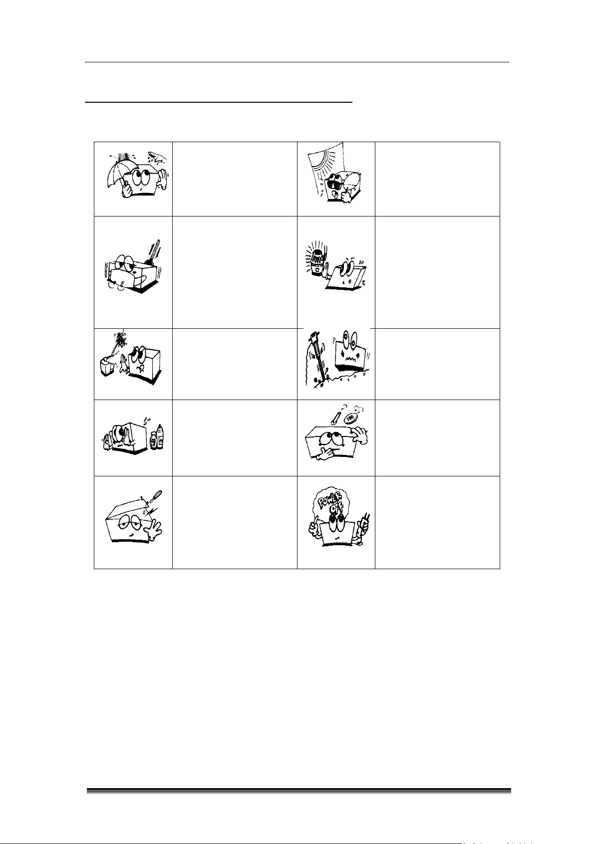
0.4 General precautions on environment
Do not keep or operate the equipment under the environment listed below.
Avoid placing in an area
exposed to moisture. Do
not touch the equipment
with wet hand.
where high variation of
temperature exists.
Operating temperature
ranges from 5
Operating humidity
℃ ~ 40℃.
ranges from 30% ~ 85 %.
Avoid exposure to direct
sunlight
Avoid in the vicinity of
electric heater.
Avoid placing in an area
where there is an
excessive humidity rise
or ventilation problem.
Avoid placing in an area
where chemicals are
stored or where there is
in danger of gas leakage.
Do not disjoint or
disassemble the device.
Bistos Co., Ltd. does not
have liability of it.
Avoid placing in an area
where there is an
excessive shock or
vibration.
Avoid dust and especially
metal material enter into
the equipment
equipment is not fully
ready to operate.
Otherwise, the
equipment could be
damaged.
Page 15

BT-770 Operation manual
14
P/N : 770-ENG-OPM-EUR-R01
Bistos Co., Ltd.
2019.06
1 System basics
1.1 Intended use
The BT-770 Patient Monitors acquire the physiological signals such as ECG, respiratory rate,
non-invasive blood pressure (NIBP), blood oxygen saturation (SpO
signals are converted into digital data and processed, examines the data for alarm conditions
and display them. The monitor also provides an operation control panel for users. The patient
monitor intend to use in hospital clinical area such as intensive care units, cardiac care units,
operating room, emergency department, to provide additional information to the medical and
nursing staff about the physiological condition of the patient. The BT-770 patient monitors are
intended to be used only under regular supervision of clinical personnel. It is suitable for adult
and pediatric, neonate. The intended locations of use are hospitals and clinics.
1) Intended patient population
- Adult (>18 years adults) and Pediatrics (30 days < and <18 years) and Neonate (0
days< and <30days)
) and temperature. The
2
2) Intended user profile
- Doctor, physicians or nursing staff who is qualified personnel
- Basic experiences or knowledge on medical field, especially on patient monitoring
- Trained or requested to read IFU before use
3) Environment of use
- Hospital and clinic
- Requirements: Stable power source
4) Scope of application
This monitor is suitable for bedside monitoring of patient. This monitor enables ECG,
respiration (RESP), pulse rate (PR), blood oxygen saturation (SpO
), noninvasive blood pressure
2
(NIBP) and temperature (TEMP) monitoring. It is equipped with a replaceable built-in battery to
provide convenience for the patient movement in hospital.
5) Indications and contraindications
Blood oxygen saturation (SpO2)
Indication:
- Monitoring effectives of oxygen therapy
- A reading is needed to facilitate the completion of an early warning score to inform
clinical assessment
- Sedation or anesthesia
- Transport of patients who are unwell and require oxygenation assessment
Page 16

BT-770 Operation manual
15
P/N : 770-ENG-OPM-EUR-R01
Bistos Co., Ltd.
2019.06
- Haemodynamic instability (e.g. cardiac failure or Myocardial Infarction)
- Respiratory illness e.g. asthma, chronic obstructive pulmonary disease
- Monitoring during administration of respiratory depressant drugs, e.g. opiate
epidural or patient-controlled analgesia.
- Assessing oxygen saturation during physical activity e.g. in pulmonary rehabilitation
Contraindications
- Pulse oximetry does not give an indication of haemoglobin so if the patient is
profoundly anaemic then their oxygen saturation may by normal but they may still be
hypoxic
Source: NHS. “Clinical Procedure_ Procedure for Pulse Oximetry/SPO2”. Wirral Community NHS Trust. Sep, 2013
Non-invasive blood pressure (NIBP)
Indication:
- To determine a patient’s blood pressure
- Screen for hypertension
- Following the effect of anti-hypertensive treatments in a patient to optimize their
management
- Assessing a person’s suitability for a spot or certain occupations
- Estimation of cardiovascular risk
- Determining for the risk of various medical procedure
- Figuring out whether a patient is clinically deteriorating or is at risk.
Contraindications
- Oscillometric blood pressure devices may not be accurate in patients with weak or
thready pulse
- In patients with heart beats below 50 beats/minutes, even if the rhythm is regular,
some of the semi-automatic devices are unable to reduce their deflation rate
sufficiently so that too rapid a falling in cuff pressure results in underestimation of
systolic blood pressure and overestimation of diastolic blood pressure.
- Do not apply to limb with AV fistula, significant injury or burn, or lymph node removal
post mastectomy.
Source: [1] NHS. “Clinical Procedure_ Procedure for Blood Pressure Monitoring”. Wirral Community NHS Trust. Dec,
2013
[2] Clinical Quality& Patient Safety Unit, QAS. Clinical Practice Procedures: Assessment/Non-invasive blood
pressure. Queensland Government, 2016. https://www.ambulance.qld.gov.au/clinical.html
Electrocardiography (ECG)
Indication:
- The electrocardiogram (ECG) has proven to be among the most useful diagnostic test
in clinical medicine. It is routinely used in the evaluation of patients to detect
myocardial injury, ischemia and the presence of prior infarction, in the assessment of
patients with electrolyte abnormalities, drug toxicities and implanted defibrillators
and pacemakers.
Page 17

BT-770 Operation manual
16
P/N : 770-ENG-OPM-EUR-R01
Bistos Co., Ltd.
2019.06
- In addition to its usefulness in the evaluation of ischemic coronary disease, the ECG,
in conjunction with ambulatory ECG monitoring, is of particular use in the diagnosis of
disorders of the cardiac rhythm and in the evaluation of syncope. Other common uses
of the ECG include the assessment of metabolic disorders and side effects of
pharmacotherapy, as the evaluation of primary and secondary cardiomyopathic
processes, among others.
Contraindications
- No absolute contraindications to performing an ECG exist, other than patient refusal.
Some patients may have allergies or, more commonly, sensitivities to the adhesive
used to affix the leads; in these cases, hypoallergenic alternatives are available from
various manufacturers.
Source: Tarek, A. “Electrocardiography”,<Medscape>, Apr 17, 2017
Temperature (TEMP)
Indication:
- To obtain the baseline temperature to enable comparisons to be made with future
recordings
- To enable close observation in resolving hypothermia/hyperthermia
- To observe and monitor patients for changes indicating an infection
- To monitor the effect of treatment for antimicrobial therapy for infection
- Using before and during a blood transfusion to monitor for signs of a reaction
Contraindications
- No known contraindications
1.2 Operating principle
Refer to the chapters for every physiological parameter from chapter 7 to chapter 12.
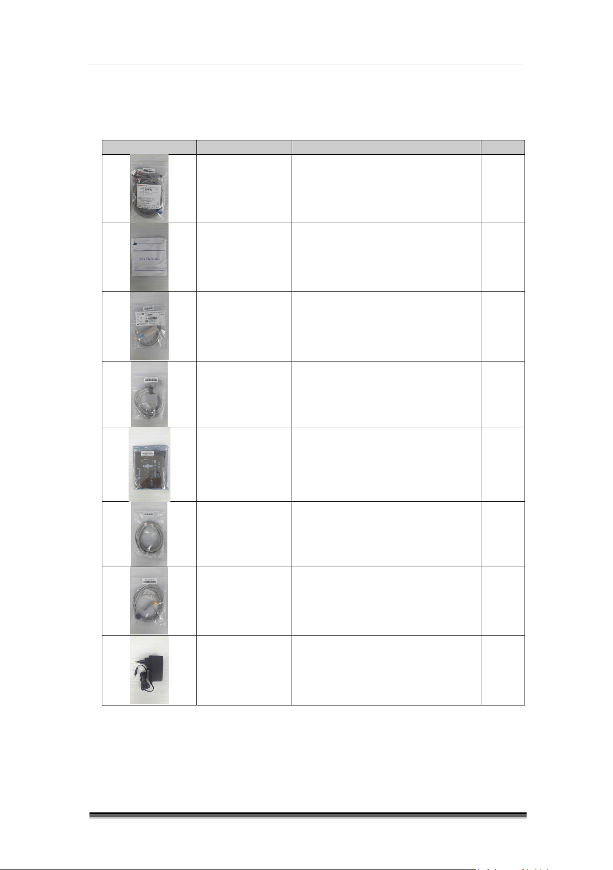
1.3 System configurations
Basic configuration of BT-770
• Main body with 12 inch touch screen and built-in lithium-ion battery
• ECG cable and electrode
• Adult SpO2 probe and extension cable
• Non-invasive blood pressure cuff
• Temperature probe
• AC/DC adapter
Page 18
BT-770 Operation manual
17
P/N : 770-ENG-OPM-EUR-R01
Bistos Co., Ltd.
2019.06
Picture
Name
Description
Qty
Options of BT-770
• External plug-in printer
ECG cable and
lead wire
(standard)
Measures ECG 1ea
ECG electrode
(standard)
Adult SpO2
sensor
(standard)
SpO2 extension
cord
(Standard)
Adult NIBP cuff
(standard)
NIBP extension
tube
(standard)
Electrode for ECG measurement 1ea
SpO2 sensor for adult 1ea
Cord to connect the SpO2 sensor and
main body
1ea
Measures NIBP for adult 1ea
Tube to connect the NIBP cuff and
main body
1ea
Temperature
sensor
(Standard)
Adapter
(Standard)
Measures the body temperature 1ea
For power supply 1ea
Page 19
BT-770 Operation manual
18
P/N : 770-ENG-OPM-EUR-R01
Bistos Co., Ltd.
2019.06
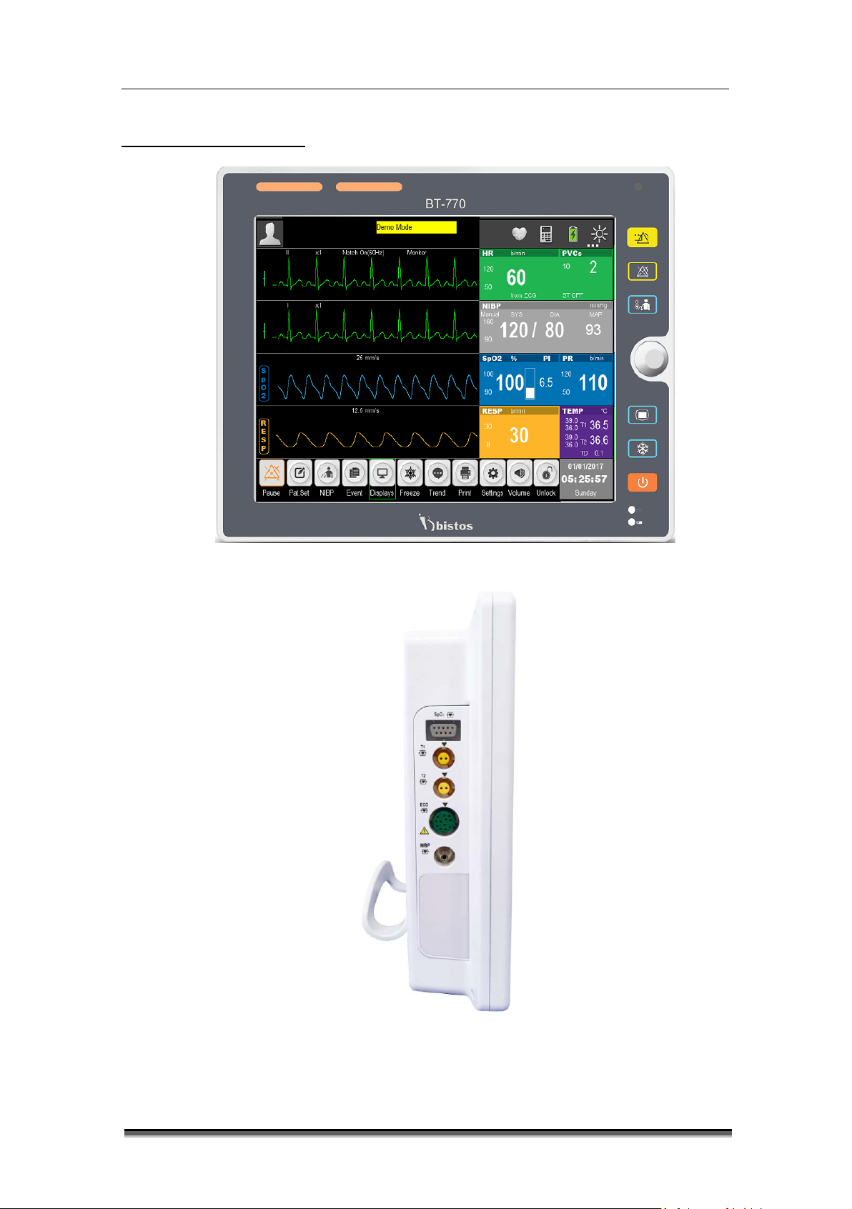
Figure1-1: Front view
Figure1-2 : Side view
1.4 Product outlook
Page 20
BT-770 Operation manual
19
P/N : 770-ENG-OPM-EUR-R01
Bistos Co., Ltd.
2019.06
Figure1-3 : Rear view
Page 21
BT-770 Operation manual
20
P/N : 770-ENG-OPM-EUR-R01
Bistos Co., Ltd.
2019.06
Indicates the priority of physiological alarm and technical
- Low priority: Yellow, constant on
- Power On: Press down the key more than 2 seconds.
system will shut down 3 seconds”.
- On: The battery is being charged or has been fully
battery.
Turned on when the monitor is being powered by the
To pause the alarm sound. Alarm pause time can be set
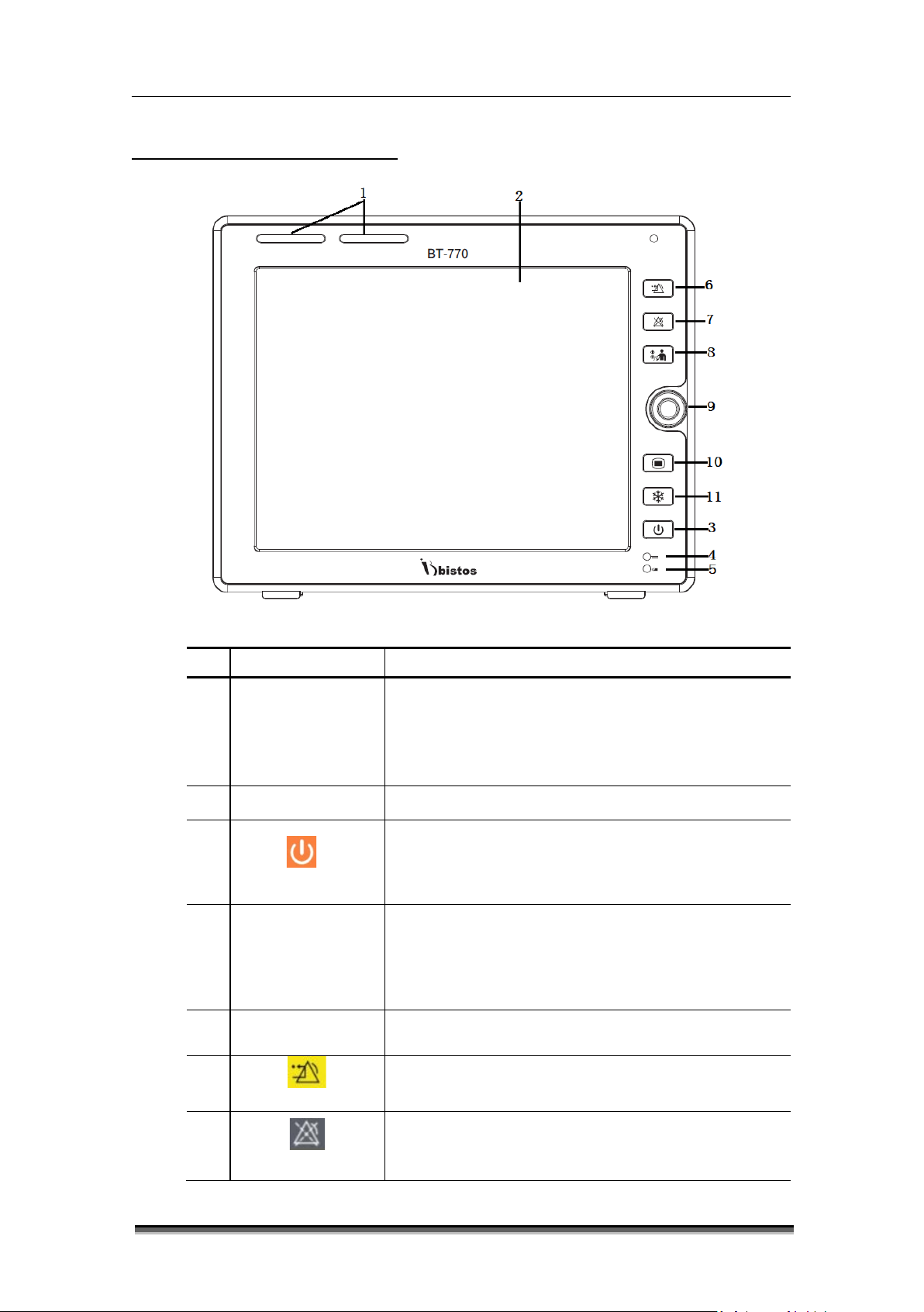
1.5 Description of monitor
1
2
3
Name Description
Alarm indicator
Display area Display the waveform and measured value
[Power]
Battery indicator
4
DC power indicator
5
Figure1-4: Front view
alarms in different colors and flashing frequencies.
- High priority: Red, fast flashing (1.4 - 2.8 Hz)
- Medium priority: Yellow, slow flashing (0.4 - 0.8 Hz)
- Power Off: Press down the keys more than 2 seconds
and the system will display the alarm message “The
charged.
- Off: The battery has not been installed.
- Flashing: The monitor is being powered by the
adapter.
6
[Alarm reset]
7
[Alarm pause]
To reset the alarm condition.
as 1 , 2, 3, 4, 5, 10, 15 minutes, and permanent. Default
setting is 2 minutes.
Page 22
BT-770 Operation manual
21
P/N : 770-ENG-OPM-EUR-R01
Bistos Co., Ltd.
2019.06
8
9
10
11
[NIBP start/stop]
Control knob
[Setting]
Start and stop the non-invasive blood pressure
measurement.
Rotate: move the cursor.
Press: select the menu or execute a command.
Enter to the setting mode. Press again to close the
setting mode.
Freeze/unfreeze the waveform.
[Freeze]
1
2
3
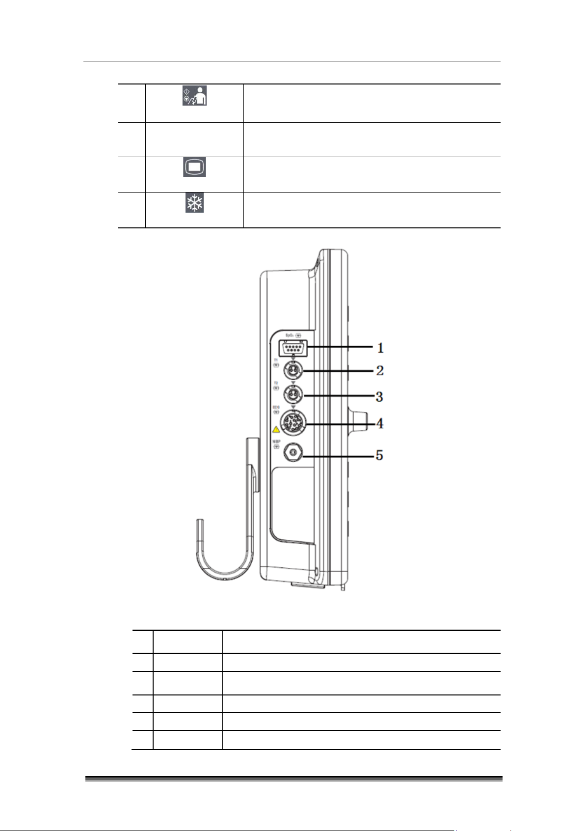
4
5
Figure1-5: Side view
Name Description
SpO2 SpO2 cable interface
T1 Temperature probe interface
T2 Temperature probe interface
ECG ECG cable interface
NIBP NIBP cuff interface
Page 23
BT-770 Operation manual
22
P/N : 770-ENG-OPM-EUR-R01
Bistos Co., Ltd.
2019.06
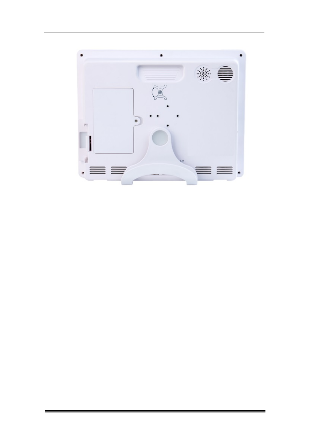
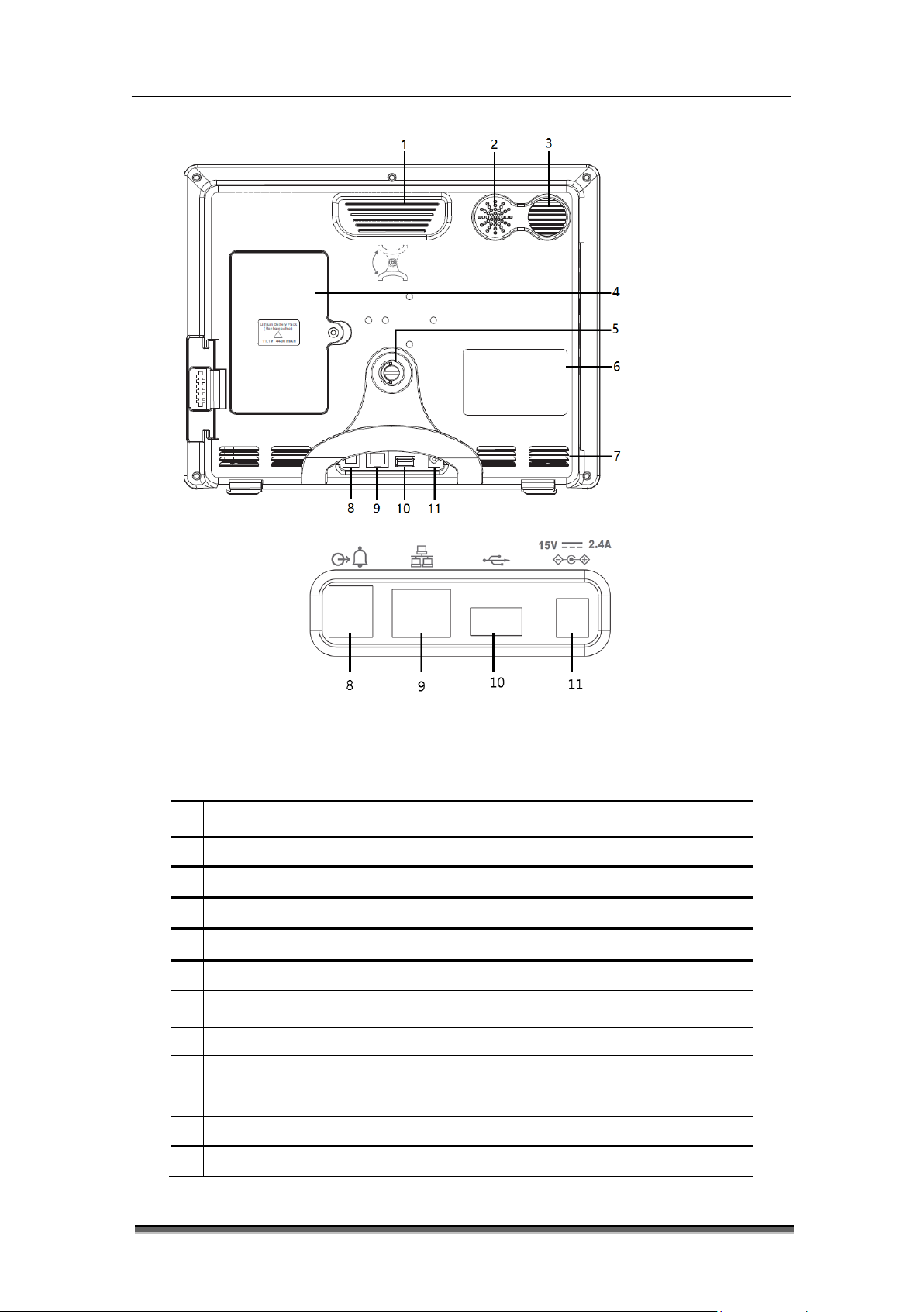
Figure1-6: Rear view
1
2
3
4
5
6
7
Auxiliary output interface Nurse call
8
9
10
Name Description
Handle Handle for main body transport
Speaker holes For alarm and synchronizing sound
Air outlet Heat dissipation
Battery cover Battery compartment cover
Bracket To wall mount the monitor
ID label Identify the monitor information
Air intake For ventilation
Network port For CMS
USB port For trend or software upgrade
11
Power adapter 15V, 2.4A adapter
Page 24
BT-770 Operation manual
23
P/N : 770-ENG-OPM-EUR-R01
Bistos Co., Ltd.
2019.06
Include patient information, alarm status icon,
mode, it displays “DEMO”.
Mainly display the waves of physiological
left side.
Show the corresponding parameter measured
- RESP
Display the network status, battery status,
Shows the hotkeys, which are frequently used for
some common operations.
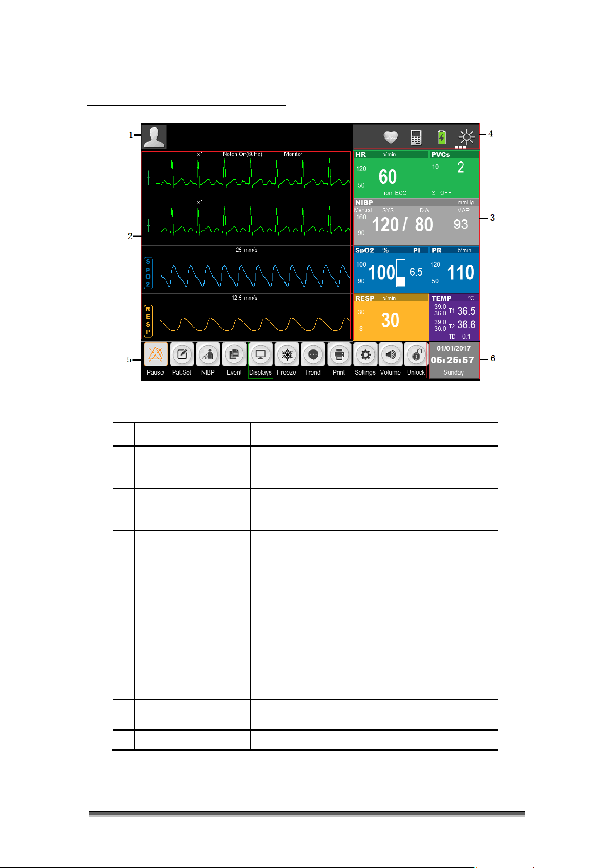
1.6 Understanding the display
Figure 1-7: Standard display
1
2
Name Description
Information area
Waveform area
physiological and technical alarms. In DEOM
parameters with name of the parameter on the
value and current upper and lower alarm limits of
each parameter module. The parameters are
shown in fixed position, that is, from top to
3
Parameter area
bottom and from left to right:
- ECG
- NIBP
- SpO
and PR
2
- TEMP
Information Tip Area
4
5
6
Hot key icons
Date and Time area Display the current date and time.
automatic identification screen brightness icon.
Page 25
BT-770 Operation manual
24
P/N : 770-ENG-OPM-EUR-R01
Bistos Co., Ltd.
2019.06
1.7 Smart Hotkeys
Smart hotkeys are graphic hotkeys displayed at the bottom of the main screen of the monitor,
and enable the user to use specific features conveniently.
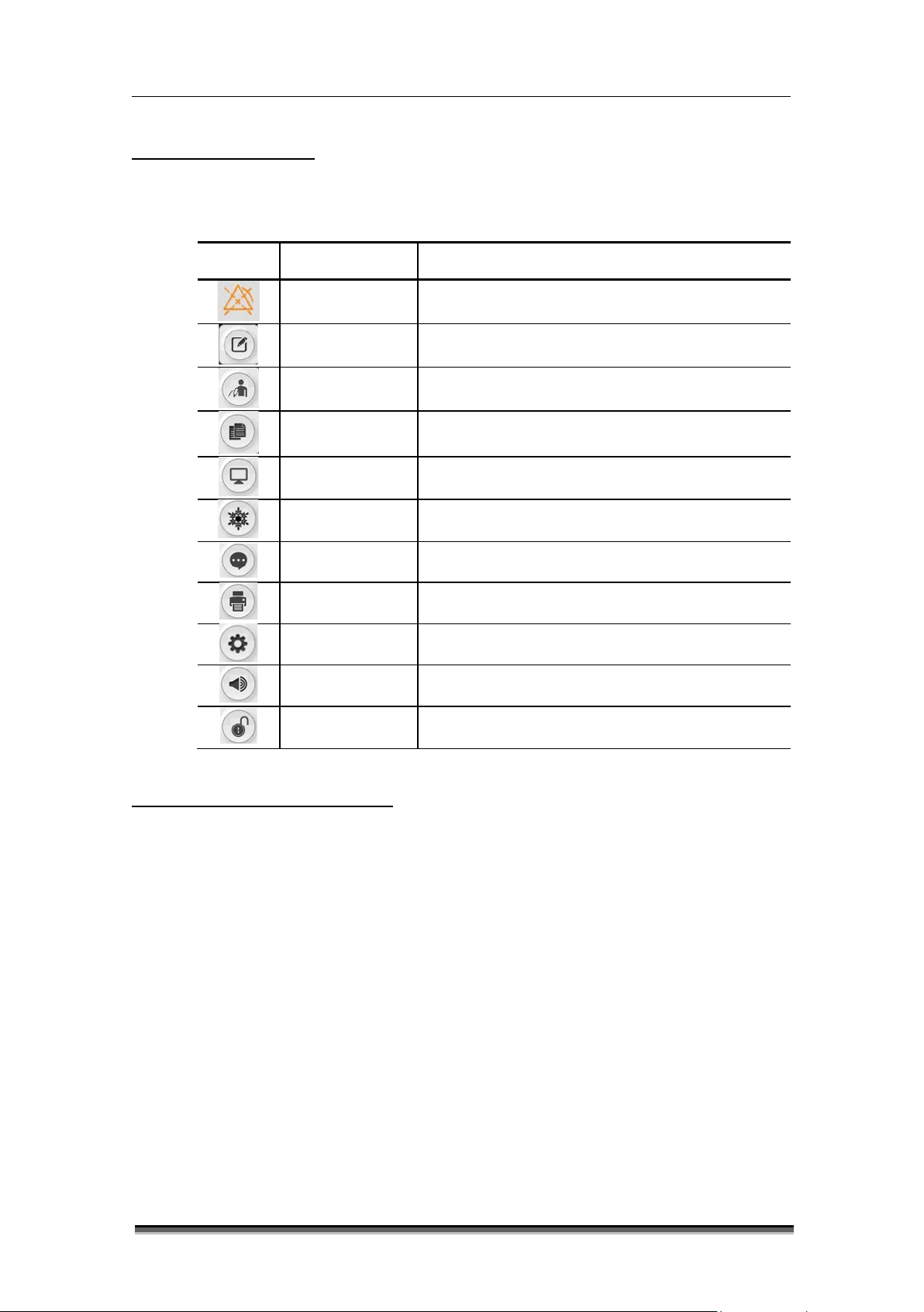
Key Name Description
[Pause] Alarm pause
[Pat. Set] Patient information setting
[NIBP] NIBP measurement start and stop
[Event] Manual event mark
[Displays] Change the display format
[Freeze] Freeze the waveform
[Tre nd] Trend display
[Print] Print key
[Settings] Setup menu
[Volume]
[Unlock]
Volume setup key
Touch screen lock key
1.8 Essential performance
This device Multi-parameter Patient Monitor provides various patient vital signs such as pulse
rate, ECG, respiration, blood oxygen saturation, blood pressure and temperature by placing or
inserting the various sensors to the appropriate site of patient. The device is composed with
display, control circuit and panel, and input part for various sensors. It detects ECG, SpO2, NIBP,
etc. using ECG cable and specific probes and sensors. The detected analog signal amplifies and
converted to digital. This concerted data feed to the CPU and converted to the display format
as number and waveform. This device is incorporated with alarm system. The alarm generated
when the detected signal range is beyond the user set alarm limits.
Page 26

BT-770 Operation manual
25
P/N : 770-ENG-OPM-EUR-R01
Bistos Co., Ltd.
2019.06
WARNING
All analog and digital devices connected to the monitor must be certified by IEC
input/output part may be connected.
2 Preparing for operations
2.1 Installation
To ensure normal working of the monitor, read this chapter before use, and install as required.
standards (e.g. IEC 60950 Data processing equipment standard and IEC 60601-1
Medical equipment standard). Furthermore, all configurations shall comply with
valid version of IEC 60601-1 standard. The personnel connecting additional devices
to the input / output signal ports are responsible for the compliance with IEC
60601-1 standard. If there is any question, please contact Bistos.
If the patient cable interface and network interface are connected with multiple
devices, the total electric leakage current cannot exceed the allowable value.
The copyright of monitor software belongs to our company. Without permission,
any organization or individual shall not interpolate, copy or exchange by any means
or form.
When the monitor is combined with other devices, it must comply with IEC 60601-
1:2005 + A1:2012, and should not be connected with multiple socket outlet or
extension cord.
Do not connect the device on other equipment or network, to which a signal
Prior to installation, the operator must ensure that the following space, power, environmental
requirements are met.
2.1.1 Unpack and check
BT-770 patient monitor was inspected rigorously at the factory before delivery, in order to
avoid being hit when transported, carried out careful packaging. Before unpacking, carefully
inspect the package. If any damage, please immediately contact the Bistos. Unpack in the
correct way, carefully remove the monitor and accessories from the box and check with the
packing list. Check if there is any mechanical damage, the all listed are completely packed. If
you have questions, please contact the marketing department of Bistos or agency.
Please keep the packing box and materials for use in future transporting or storage.
Page 27

BT-770 Operation manual
26
P/N : 770-ENG-OPM-EUR-R01
Bistos Co., Ltd.
2019.06
Relative humidity
30 % ~ 85 % (Non-condensing)
Atmospheric pressure
700 ~ 1060 mbar (hPa)
Transportation
Prevent severe shock, vibration, rain and snow splashing during transport.
The packaged monitor should be stored in well-ventilated room with
corrosive gases.
WARNING
Ensure that the monitor is used under specified environment. Fail to do this, the
damage to equipment and other unforeseen consequences.
2.1.2 Placement requirements
Equipment installation must meet:
- The left and right side of the monitor should have space more than 100 cm from the wall
- Back on the monitor should have space more than 50 cm.
- Ensure that the operating floor and the monitor have enough space for connecting the
accessory wires.
2.1.3 Power requirements
- DC power supply adapter
Input: A.C. 100 V - 240 V, 50/60 Hz
Output: D.C. 15 V, 2.5 A
- Built-in rechargeable lithium-ion battery: D.C. 11.1 V, 4400 mAh
2.1.4 Environmental requirements
The storage, transport and use of the monitor must meet the following environmental
requirements.
Operating
Ambient temperature
environment
Storage
ambient temperature -20 ℃ ~ 60℃, relative humidity 0 ~ 95 % (Non-
condensing), atmospheric pressure 700 ~ 1060 mbar(hPa), and without
The operating environment of the monitor should avoid noise, vibration, dust, corrosive or
flammable and explosive materials. In order to allow air flowing smoothly and achieve good
heat dissipation, at least 2 inches (5cm) clearance should be kept around the device.
5℃ ~ 40 ℃
When the device is moved from one environment to another, the device may have
condensation due to the differences in temperature or humidity. In this case, wait until the
condensation disappears before using the device.
technical specifications declared in this manual may not be met and it may result in
Page 28

BT-770 Operation manual
27
P/N : 770-ENG-OPM-EUR-R01
Bistos Co., Ltd.
2019.06
WARNING
Do not try to open the monitor when the power is connecting.
2.2 Connecting to power
During the operation, do not disconnect any cable.
Connect to power adapter in the following steps:
- Make sure that the AC power supply meets the following specifications: a.c.100V-
240V, 50/60Hz.
- Use the power adapter provided with the monitor. Plug the power adapter into the
power connector of the monitor, and plug the other end of the power adapter into
the mains (low voltage power supply network facilities) power outlet with protective
earth.
Page 29

BT-770 Operation manual
28
P/N : 770-ENG-OPM-EUR-R01
Bistos Co., Ltd.
2019.06
WARNING
If the monitor is damaged, or fails to work normally, do not use it for patient
monitoring. Please contact the maintenance personnel or Bistos immediately.
3 Basic operations
3.1 Turn on
3.1.1 Check the monitor
- Before turn on the monitor, check whether there is mechanical damage to the monitor,
and whether the external cables and accessories are connected correctly.
- Plug the power adapter into the AC power outlet. If using battery power, make sure the
battery is fully charged.
- Check all the functions required for patient monitoring to make sure that the monitor
operates properly.
3.1.2 Start the monitor
If finish to check the monitor, it is ready to start the monitor.
Press the [Power] key, the yellow warning lights flash once and the system enter the
program reading interface; finally the system makes a “tick” sound, the boot screen disappears,
and the system enters the main interface.
- If any fatal error occurs during self-test, the system will alarm. If this case persists,
please stop to using the monitor and contact the maintenance personnel or Bistos.
- Check all available monitor functions to ensure that the monitor operate properly.
- If the monitor equipped with a battery, charge the battery after each use to ensure
sufficient power.
- After unpacking, when use the monitor first time, the monitor should be powered
with adapter.
3.1.3 Connect the sensors
Connect the required sensor to the monitor and the monitoring site of patient.
Page 30

BT-770 Operation manual
29
P/N : 770-ENG-OPM-EUR-R01
Bistos Co., Ltd.
2019.06
CAUTION
not recommended.
3.1.4 Start monitoring
Start monitoring in the following steps:
- Check if the patient cable and the sensor are connected properly.
- Check if the settings of the monitor are corrects, such as patient type.
- For the details of parameter measurement or monitoring, see the appropriate
section.
- The operator can operate according to their own habits, standing in front, left or
right of the monitor, easy to observe and operate the monitor.
3.2 Turn off
Turn off the monitor in the following steps
- Disconnect the cables and sensors connected to the patient.
- Press and hold the [Power] key for 2 seconds to pop up the 3 seconds countdown
window, and the monitor turns off in 3 seconds.
• If the monitor is not turned off properly, you can simply disconnect the power
to shutdown forcibly. But the forced shutdown may cause data loss, and it is
3.3 Basic operations
3.3.1 Using the control knob
Control knob can be used to perform the following operations:
- Rotate: Rotate control knob clockwise or counter clockwise to move the cursor.
- Press: Press control knob to perform an action, such as access to a menu or execute a
command.
Control knob is the main control means. On the interface or the menu, the green highlighted
box that moves with the knob turning is called the cursor. By turning the control knob, you can
position the cursor in order to perform the desired operation.
3.3.2 Using keys
Page 31

BT-770 Operation manual
30
P/N : 770-ENG-OPM-EUR-R01
Bistos Co., Ltd.
2019.06
The monitor has three types of keys:
- Soft keys: Within the display these keys allow quick access to certain menus or performing
certain actions, including:
• Parameter hotkeys: Select a parameter area and enter the appropriate parameter
setup menu, including drug calculation and time setup.
• Wave hotkeys: Select a wave area and enter the appropriate parameter setup.
• Smart hotkeys: The shortcut keys that the user can operate quickly are displayed at
bottom of the screen. Refer to ‘1.7 Smart Hotkeys’.
- Hard keys: The physical keys on the monitor, such as the [Alarm pause] key on the front
panel.
- Popup keys: Menu keys relevant to the tasks that automatically appear on the monitor
screen when need, such as, the confirmation key popped up when you need to confirm
the change.
3.3.3 Using the touch screen
Click on the touch screen to quickly and easily perform specific operation.
3.3.4 Using soft keyboard
If you choose a menu which needs to enter characters, the system will display the soft
keyboard on the screen. If you finish entering, press [Enter] key to confirm that you have
finished entering and close the soft keyboard.
3.3.5 Using menu
Select the [Settings] smart key on the monitor or press the [Setting] key on the monitor
panel to open the “Settings” mode as shown below. You can set-up the mon it o r.
Page 32

BT-770 Operation manual
31
P/N : 770-ENG-OPM-EUR-R01
Bistos Co., Ltd.
2019.06
Figure 3-1: ”Setting” menu
The style of other menus is basically similar to the “Settings”, and generally consists of the
following components:
• Menu title: A title of the current menu.
• Close menu: Close the current menu. Exit the current menu or close the current menu
and return to the previous menu.
• Main display area: Display options, buttons or prompt messages. The symbol “>>”
indicates that selecting this option can enter the corresponding submenu.
• Confirmation key area: Some menus contain a confirmation key area to confirm the
menu operations, including confirmation and cancel key.
3.4 Operation mode
The monitor has 2 operating modes, of which the demo mode is protected by a password.
1. Monitoring mode (operating mode)
This is the daily operating mode of patient monitoring; you can change some settings in
accordance with the patients, such as alarm limits. However, when the patient is discharged,
the monitor will restore these settings to default according to pre-set configuration.
2. Demo mode
This mode is protected by a password for demonstration purpose only.
• Enter the demo mode:
Page 33

BT-770 Operation manual
32
P/N : 770-ENG-OPM-EUR-R01
Bistos Co., Ltd.
2019.06
WARNING
The demo mode is mainly used to show the monitor’s performance and for
thus affecting patient monitoring, and delaying diagnosis and treatment.
Select [Settings]Smart Hotkey or press [Setting] key on the monitor panel
→ “Settings”;
Select “Demo Mode>>” → enter the password and confirm, and the monitor
enters the demo mode.
• Exit demo mode:
Select [Settings]Smart Hotkey or press [Setting] key on the monitor panel
→ “Settings”;
Select “Exit Demo >>” and the monitor exits the demo mode.
user training. In actual clinical use, the demo function is prohibited in order to
avoid mistaking the displayed waves and parameters as those of the patient,
3.5 Measurement setup
This section only describes the general settings of measuring wave in monitor mode; for other
specific settings of each parameter, please refer to the appropriate section.
Select the wave area of a parameter to enter the appropriate setup menu. The setup menu
defines the specific wave setup of the parameter, such as wave gain and wave speed. You may
set the waves of different parameters as needed.
3.6 Freezing waves
In the patient monitoring process, you can freeze the wave on the screen, review and carefully
observe the patient's condition during this time. Freeze / unfreeze the wave as follows:
Select 【Freeze】 hotkey or press the [Freeze] key on the monitor panel to freeze the
displayed wave of the monitor.
Select 【Freeze】 hotkey or press the [Freeze] key on the monitor panel again to release
the freezing state.
Page 34

BT-770 Operation manual
33
P/N : 770-ENG-OPM-EUR-R01
Bistos Co., Ltd.
2019.06
3.7 Other common setup
The common setup of the monitor is the general setup that defines how the monitor works, for
example: alarm volume setting. They may affect the setup of multiple measurements or display
interfaces.
3.7.1 Defining the monitor
When install the monitor or change the usage occasion, the monitor should be defined as
follows:
Select [Settings]Smart Hotkey or press [Setting] key on the monitor panel →
“Settings”.
Select “User Maintenance >>” →enter the password and confirm → “User Maintenance”
menu.
Select “Device Name”: Enter device name through the soft keyboard on the screen.
Select “Department”: Enter the sector and department using the device through the
soft keyboard on the screen.
Select “Bed Number”: Enter the bed number through the soft keyboard on the
screen.
3.7.2 Language setup
Set the monitor language in the following steps:
Select [Settings]Smart Hotkey or press [Setting] key on the monitor panel →
“Settings”.
Select “User Maintenance >>” →enter the password and confirm →“User Maintenance”
menu.
Select “Language”, and select the option as needed:
“English”: The interface language of the monitor is English.
“Türkçe”: The interface language of the monitor is Turkish.
“Español”: The interface language of the monitor is Spanish.
“Français”: The interface language of the monitor is French.
“Italiano”: The interface language of the monitor is Italian.
“Deutsch”: The interface language of the monitor is German.
Page 35

BT-770 Operation manual
34
P/N : 770-ENG-OPM-EUR-R01
Bistos Co., Ltd.
2019.06
3.7.3 Date and time
Set the monitor time in the following steps:
Select [Settings]Smart Hotkey or press [Setting] key on the monitor panel →
“Settings”;
Select “User Maintenance >>” →enter the password and confirm →“User Maintenance”
menu.
Select “Time Setup >>” → enter “Time Setup>>” menu.
Or you can enter the “Time Setup” directly by touching the time display area on the
display.
“Date (YYYY-MM-DD)”: Set the year, month, and day.
“Time (24H)”: Set the hour, minute and second.
Select “Date Format”, and set the date format in accordance with custom
“YYYY-MM-DD” : Ye ar- Month-Day.
“MM-DD-YYYY”: Month -Day-Ye ar.
“DD-MM-YYYY”: Day-Month-Yea r.
“Time Format”, set the time format is 24H.
3.7.4 Volume control
1. Alarm Volume
Select 【Volume】smart hotkey → “Volume Setup” menu.
Select “Alarm Volume”: Set alarm volume from 1 to 9.
2. QRS Volume
Select 【Volume】smart hotkey → “Volume Setup” menu.
Select “QRS Volume”: Set QRS volume from 0 to 9. 0 means off.
3. Pulse Volume
Select 【Volume】smart hotkey → “Volume Setup” menu.
Select “Pulse Volume”: Set pulse volume from 0 to 9. 0 means off.
4. Touch Volume
Page 36

BT-770 Operation manual
35
P/N : 770-ENG-OPM-EUR-R01
Bistos Co., Ltd.
2019.06
Select 【Volume】smart hotkey → “Volume Setup” menu.
Select “Touch Volume”: Set touch volume from 0 to 9. 0 means off.
5. Key Volume
Select 【Volume】smart hotkey → “Volume Setup” menu.
Select “Key Volume”: Set key volume from 0 to 9. 0 means off.
3.7.5 Setting parameter unit
You can select a preferred unit through the following operations
Select [Settings]Smart Hotkey or press [Setting] key on the monitor panel →
“Settings”.
Select “User Maintenance >>” → enter the password and confirm →“User Maintenance”
menu.
Select “Unit Setup >>” →“Unit Setup” menu.
Select “Height Unit”, and select the unit “cm” / “inch” as needed.
Select “Weight Unit”, and select the unit “kg” / “lb” as needed.
“ST Unit” fixed as “m V ”, is not optional.
Select “Pressure Unit”, and select the unit “mmHg” / “kPa” as needed.
Select “TEMP Unit”, and select the unit “℃” / “℉”as needed.
Page 37

BT-770 Operation manual
36
P/N : 770-ENG-OPM-EUR-R01
Bistos Co., Ltd.
2019.06
WARNING
Whether the patient is admitted or not, the system will give a default value to
ventricular premature beats, and fails to perform ST segment analysis.
4 Patient information management
Connect the patient to the monitor, and the monitor will display and store the physiological
data of the patient, so the patient can be monitored without admitting the patient. However,
admitting the patient correctly is very important.
If the monitor has admitted the patient, it is recommended to operate the monitor to
discharge the current patient before connecting to (not admitted) the next patient. Otherwise,
the data of the previous patient will be stored in the data of the current patient.
“Patient Type” and “Pace Maker”, “Patient Type” default “Adult”, “Pace Maker”
default “No”, and the user must confirm that the default value is appropriate for
the patient being monitored.
For patients with pacemakers, “Pace Maker” must be set to “Yes”. Otherwise, the
pacing pulse will be treated as normal QRS wave group, and the system is unable
to detect the alarm status of “ECG Signal weak”.
For patients without a pacemaker, “Pace Maker” must be set to “No”. Otherwise,
the system is unable to detect the arrhythmias (including PVCs count) related to
4.1 Patient setup menu
You can manage the patient through the “Patient” menu. To enter “Patient” menu, operate as
follows:
Select [Settings]Smart Hotkey or press [Setting] key on the monitor panel → “Settings”
→ “Patient >>” → “Patient” menu;
OrSelect [Pat. Set] Smart Hotkey to enter “Patient” menu, as shown in Fig. 4-1.
Figure 4-1 “Patient” menu
Page 38

BT-770 Operation manual
37
P/N : 770-ENG-OPM-EUR-R01
Bistos Co., Ltd.
2019.06
4.2 Admitting a patient
Admit a patient as follows:
In “Patient” menu, select “Quick Admit” → “Warning” message → “OK” → “Quick Admit”
menu, as shown in Figure 4-2.
Figure 4-2 “Quick Admit” menu
Select “Patient Type”, and set the patient category as needed: “Adult” and “Pediatric” and
“Neonate”.
Select “Pace Maker”, and set whether the patient wears a pacemaker according to the
patient condition: “Yes” or “No”.
After setting, select “OK” to save the current setup or select “Cancel” and do not save the
current setup.
4.3 Patient information
To edit patient information, operate as follows:
In the “Patient” menu, select “Patient Info”. The “Patient Info” menu as shown in Figure 4-3 will
be displayed.
Page 39

BT-770 Operation manual
38
P/N : 770-ENG-OPM-EUR-R01
Bistos Co., Ltd.
2019.06
Figure 4-3. “Patient Info” menu
1. Select “Last Name”, and enter patient’s surname through the soft keyboard(Letters: not more
than 20 characters).
2. Select “First Name”, and enter patient name through the soft keyboard(Letters: not more than 20
characters).
3. Select “Patient ID”, and enter the patient ID through the soft keyboard (Letters: not more than 20
characters).
4. Select “Case Number”, and enter the case number through the soft keyboard(Letters: not more
than 20 characters).
5. Select “Gender”, and set the patient’s gender.
6. Select “Patient Type”, and set the patient category as needed: Adult and Pediatric and Neonate.
7. Select “Pace Maker”, and set whether the patient wears a pacemaker.
8. Select “Height(cm)”, and set the patient’s height via the pop-up keyboard on the screen(Range: 0~
250).
9. Select “Weight (kg)”, and set the patient’s weight via the pop-up keyboard on the screen(Range: 0
~350).
10. Select “Blood Type”, and set the patient’s blood type: A, B, AB or O.
11. Select “Admission Date (MM-DD-YYYY)”, and set the date of admitting the patient.
Page 40

BT-770 Operation manual
39
P/N : 770-ENG-OPM-EUR-R01
Bistos Co., Ltd.
2019.06
12. Select “Birthday (MM-DD-YYYY)”, and set the birth date of the patient.
After setting, select “OK” to save the current setting or select “Cancel” and do not save the current
setting.
4.4 Discharging a patient
To discharge a patient, operate as follows:
In the “Patient” menu, select “Discharge Patient” → “Warning” message → “OK” to finish the
operation of discharging a patient.
After the patient is discharged, all the information of the patient stored in the monitor will be
cleared. Therefore, discharge the patient only when needed.
4.5 Clear alarms
To clear alarms, operate as follows:
In the “Patient” menu, select “Clear Alarms” → “Warning” message → “OK” to finish the
operation of clear alarms.
After the alarm is cleared, all the information of alarms stored in the monitor will be cleared.
Therefore, clear alarm only when needed.
4.6 Clear trend
To clear trend, operate as follows:
In the “Patient” menu, select “Clear Tabular Trend” → “Warning” message → “OK” to finish the
operation of clear tabular trend.
After the tabular trend was cleared, all the information of tabular trend stored in the monitor
will be cleared. Therefore, clear tabular trend only when needed.
4.7 Clear NIBP trend
To clear NIBP trend, operate as follows:
In the “Patient” menu, select “Clear NIBP Trend” → “Warning” message → “OK” to finish the
operation of clear NIBP trend.
After the NIBP trend was cleared, all the information of NIBP trend stored in the monitor will
be cleared. Therefore, clear NIBP trend only when needed.
Page 41

BT-770 Operation manual
40
P/N : 770-ENG-OPM-EUR-R01
Bistos Co., Ltd.
2019.06
5 Display format
The monitor has four display format, which are “Normal Screen”, “Big ECG Screen”, “Big font
Screen”, and “ECG 7-Lead Full-Screen”. The user can select the display format according to
needs, and get different screen information.
5.1 Selecting user interface
Select the user interface as follows:
Select [Displays] smart hotkey→ Screen Select;
Select the display format according to needs:
“Normal Screen”: Standard interface.
“Big ECG Screen”: Big ECG interface.
“Big font Screen”: Big font interface.
“ECG 7-Lead Full-Screen”: ECG 7-Lead Full interface.
5.2 Display description
5.2.1 Normal display format
Figure 5-1: Standard Display
Page 42

BT-770 Operation manual
41
P/N : 770-ENG-OPM-EUR-R01
Bistos Co., Ltd.
2019.06
The normal display provides the parameter wave being monitored and the parameters
displayed in the parameter area. This is the basic display of the monitor. In this display mode all
parameters, two ECG waves, one blood oxygen saturation percentage wave, one respiratory
wave are displayed.
5.2.2 Big ECG format
The big ECG format is as shown in Figure 5-2.
Figure 5-2: Big ECG format
5.2.3 Big font format
The big font format is as shown in Figure 5-3.
Page 43

BT-770 Operation manual
42
P/N : 770-ENG-OPM-EUR-R01
Bistos Co., Ltd.
2019.06
Figure 5-3: Big font format
5.2.4 ECG 7-Lead full screen format
The ECG 7-Lead full screen format is as shown in Figure 5-4.
Figure 5-4: ECG 7-Lead full screen format
Page 44

BT-770 Operation manual
43
P/N : 770-ENG-OPM-EUR-R01
Bistos Co., Ltd.
2019.06
WARNING
In any single region (e.g. ICU), it has potential danger if the same or similar
devices use different alarm setup.
6 Alarm
Alarm means that the monitor prompts the medical staff through sound and light when the
abnormal changes in vital signs are monitored or the monitor has a failure or is unable to
monitor the patient successfully.
- After setting, the alarm and other parameters of the monitor won’t be lost when the
system is power off, unless modified manually. Connect the power again and turn on the
monitor, it will resume normal working, and the alarm and other parameters remain
unchanged.
6.1 Alarm types
According to the nature of the alarm, the alarms of the monitor can be divided into
physiological alarms, technical alarms and prompt messages.
Physiological alarms
A physiological alarm is usually triggered when a physiological parameter of the patient
exceeds the alarm limit or the patient has physiological abnormalities. The information of
physiological alarm is displayed in the physiological alarm area on top of the screen.
Technical alarms
Technical alarm is also known as a system error message, which is caused by improper
operation or system failure resulting in system malfunction or monitoring result distorted.
The information of technical alarm is displayed in the technical alarm area on top of the
screen.
Prompt messages
Strictly speaking, the prompt messages are not alarms. The monitor also will display some
information associated with system status in addition to the physiological alarms and
technical alarms, and generally such information do not involve the patient's vital signs.
The prompt messages generally appear in the technical alarm area and parameters area.
6.2 Alarm condition priorities
According to the severity of the alarm conditions, the physiological alarms of the monitor can
be divided into high priority, medium priority and low priority.
High priority alarms
The patient is in critical condition that is life-threatening, and should be immediately
rescued, or the monitor has a serious mechanical failure or malfunction, causing it unable
to detect the patient's critical state and endangering the patient’s life.
Page 45

BT-770 Operation manual
44
P/N : 770-ENG-OPM-EUR-R01
Bistos Co., Ltd.
2019.06
Medium priority alarms
The patient's physiological signs are abnormal and appropriate measures or treatment
should be taken immediately, or although it won’t endanger the patient’s life, the
mechanical failure or disoperation of the monitor will affect the normal monitoring of key
physiological parameters.
Low priority alarms
The patient's physiological signs are abnormal and appropriate measures or treatment
may need to be taken, or certain monitoring function is invalid due to mechanical failure
or disoperation, but it won’t endanger the patient’s life.
The priority of all technical alarms and some physiological alarms have been set in the monitor
at the factory and cannot be modified by the user. The levels of some physiological alarms can
be modified.
6.3 Alarm mode
When an alarm occurs, the monitor uses the following audible or visual alarm to prompt the
user:
Visual alarm
Audible alarm
Alarm info
Parameter flashing
Of which, the visual alarm, audible alarm, and alarm information distinguish the alarm levels in
a different manner respectively.
6.3.1 Visual alarm
When an alarm occurs, the alarm indicator will flash in different colors and frequencies to
prompt the alarm priority.
High priority alarm: Red, fast flashes.
Medium priority alarm: Yellow, slow flashes.
Low priority alarm: Yellow, lit without flashing.
6.3.2 Audible alarm
An audible alarm is that the monitor prompts the alarm priorities with different sound
characteristics when an alarm occurs.
Page 46

BT-770 Operation manual
45
P/N : 770-ENG-OPM-EUR-R01
Bistos Co., Ltd.
2019.06
High priority alarm: Beep-beep-beep--beep-beep----beep-beep-beep--beep-beep
Medium priority alarm: Beep-beep-beep
Low priority alarm: Beep
6.3.3 Alarm information
Alarm information displayed on the physiological or technical alarm area of the monitor
indicates the corresponding alarm information when an alarm occurs. The system will
distinguish the alarm priority with different background colors:
High priority alarm: Red
Medium priority alarm: Yellow
Low priority alarm: Yellow
The following flags in front of physiological alarms are used to distinguish the alarm priorities.
High priority alarm: ***
Medium priority alarm: **
Low priority alarm: *
6.3.4 Parameter flashing
When the physiological parameter values in the parameter area will flash once per second, and
the upper limit and lower limit of the parameter will also flash at the same frequency, it
indicating that the parameter exceeds the upper limit or lower limit.
6.4 Alarm states
In addition to the above alarm modes, you can also set the monitor to the following three
alarm states as needed, and display different alarm icons on the screen:
Alarm Reset
Alarm sound off
Alarm pause
Alarm off
Page 47

BT-770 Operation manual
46
P/N : 770-ENG-OPM-EUR-R01
Bistos Co., Ltd.
2019.06
WARNING
When the alarm is off, and the alarm reminder signal is on, the system will have
alarm reminder tone.
6.4.1 Alarm reset
Select button, and you can temporarily turn off the alarm sound of currently occurring
physiological alarms of the monitor, but the alarm information is still retained. For technical
alarms, clear the alarm state, display alarm prompt information, the alarm state icon area
displays the icon. When a new physiological alarm or technical alarm occurs, the alarm
reset is automatically canceled.
6.4.2 Alarm sound off
The alarm sound can be turned off through the following operations:
Select [Settings] smart hotkey→ “Settings”.
Select “User Maintenance >>”→enter the password and confirm →“User Maintenance”
menu.
Select “Alarm Param >>”→“ Alarm Param” menu.
Set “Minimum Alarm Volume” to “0”. “Minimum Alarm Volume” range from 0 to 9, the
default value is 1.
Select 【Volume】smart hotkey →“Volume Setup” menu.
Set “Alarm Volume” to “0”.
When the alarm sound is turned off, the alarm state area on the screen shows the icon.
If “Minimum Alarm Volume” is larger than 0, the system will cancel alarm sound off state.
6.4.3 Alarm pause
Press the [Pause] smart hotkey or [Alarm pause] key on the monitor panel to
temporarily stop the alarm of the monitor in the following steps:
[Pause]smart hotkey will appear magnified and reverse colored icon.
The light alarm and audible alarm of the physiological alarms are suspended, and the
alarm information is not displayed.
The remaining time of alarm pause is displayed in the physiological alarm area.
Alarm parameters and upper / lower limit stop flashing.
Page 48

BT-770 Operation manual
47
P/N : 770-ENG-OPM-EUR-R01
Bistos Co., Ltd.
2019.06
WARNING
When the alarm volume is set to ‘0’ or the alarm pause time is set to permanent,
operator should use this feature carefully.
The audible alarm and light alarm of technical alarms are suspended, but the alarm
message is still displayed.
After the alarm pause is finished, the monitor will automatically cancel the alarm pause state.
During the alarm pause, you can also press [Pause] smart hotkey or [Alarm pause] key
on the monitor panel to cancel the alarm pause manually.
You can set the alarm pause time as follows:
Select [Settings]Smart Hotkey or press [Setting] key on the monitor panel →
“Settings”.
Select “User Maintenance >>” → enter the password and confirm →“User Maintenance”
menu.
Select “Alarm Param >>”→“ Alarm Param” menu.
Select “Alarm Pause Time”, and set the alarm pause time.
“1min” /“2min” /“3min” /“4min” /“5min” /“10min” /“15min” “Permanent”. By
default, the alarm pause time is 2 minutes.
“Permanent” means alarm off.
It is recommended that the SpO2 alarm pause time shall not more than two minutes.
6.4.4 Alarm off
As shown in 6.4.3, if the “Alarm Pause Time” is set to “Permanent”, press the [Pause] smart
hotkey or [Alarm pause] key on the monitor panel, and the monitor will turn off the alarm.
In this case, except the alarm prompt characteristics maintained in alarm pause state:
[Pause] smart hotkey will appear magnified icon.
The physiological alarm area displays “Alarm Pause”.
You can press the [Pause] smart hotkey again to manually cancel the alarm off.
If the monitor is in the alarm state of suspension or high priority technical alarm is triggered,
the alarm and the alarm off pause are automatically canceled.
the monitor does not sound an alarm when an alarm occurs. Therefore, the
Page 49

BT-770 Operation manual
48
P/N : 770-ENG-OPM-EUR-R01
Bistos Co., Ltd.
2019.06
6.5 Alarm setup
6.5.1 Setting the alarm delay time
To limit alarm of continuous measurement parameter, you can set the alarm delay time. If the
alarm condition disappears during the delay period, the monitor will not generate an alarm. In
“Alarm Param” menu, select “Alarm Delay” time and “ST Alarm Delay” time.
The specific operation is as follows:
Select [Settings] smart hotkey or press [Setting] key on the monitor panel →
“Settings”.
Select “User Maintenance >>” → enter the password and confirm → “User Maintenance”
menu.
Select “Alarm Param >>” → “Alarm Param” menu.
Select “Alarm Delay”, and set the alarm delay time as needed:
“Off”: Turn off the alarm delay.
“1s” / “2s” / “3s” / “4s” / “5s” / “6s” / “7s” / “8s”: Alarm delay time is 1 sec, 2 sec, 3
sec, 4 sec, 5 sec, 6 sec, 7 sec or 8 sec. By default, the alarm delay time is 4 seconds.
Select “ST Alarm Delay”, and set the ST alarm delay time as needed.
“Off”: ST alarm delay is off
“10s” / “20s” / “30s” / “45s” / “1min” / “2min” / “3min”: ST alarm delay time is 10
sec, 20 sec, 30 sec, 45 sec, 1 min, 2 min or 3 min. By default, the ST alarm delay time
is 20 seconds.
6.5.2 Setting the alarm reminder signal and alarm reminder interval
The alarm reminder signal can be turned on or off. When the alarm is off and the alarm sound
is off, and then the alarm reminder signal is on. You can set the alarm reminder interval as
needed: “1min” / “2 min” / “3 min”.
The specific operation is as follows:
Select 【Settings】Smart Hotkey→ “Settings” .
Select “User Maintenance >>” →enter the password and confirm → “User Maintenance”
menu.
Select “Alarm Param >>” → “Alarm Param” menu.
Select “Alarm Reminder Signal”, and set the alarm reminder signal as needed:
Page 50

BT-770 Operation manual
49
P/N : 770-ENG-OPM-EUR-R01
Bistos Co., Ltd.
2019.06
“On”: The alarm Reminder Signal is on.
“Off”: The alarm Reminder Signal is off.
Select “Alarm Reminder Interval”, and set the alarm reminder interval as needed:
“1min” / “2 min” / “3 min”: Alarm reminder interval is 1 min, 2 min or 3 min. By
default, the alarm reminder interval is 3 min.
6.5.3 Setting a parameter alarm
You can set the parameter alarm for every alarm separately. For SpO2, as an example, select
“Alarm Setup >>” in the “Settings” menu and select “SpO
menu.
1. Turn on / off alarm
Select “Alarm Switch” and set the alarm switch as follows:
” and enter the SpO2 alarm setup
2
“On”: Turn on SpO
alarm; when the parameter alarm occurs, the monitor will
2
prompt according to the set alarm level.
“Off”: Turn off SpO
alarm; icon is displayed in the parameter area, and the
2
monitor won’t prompt the parameter alarm.
2. Set the alarm priority
Select “Alarm Level”, and set the alarm priority as follows:
“Mid”: Set the alarm priority to medium.
“High”: Set the alarm priority to high.
Note: Regulatory requirements, the parameter (ECG, blood oxygen saturation, blood pressure)
can set the alarm priority high and mid.
3. Set the alarm limit
In any cases, the alarm system only allows setting the values within the effective range of the
system, and the upper alarm limit must be higher than the lower alarm limit.
Select “SpO
Low Limit” and set the lower limit of SpO2 alarm.
2
Select “SpO
Select “PR Low Limit” and set the lower limit of PR alarm.
Select “PR High Limit” and set the upper limit of PR alarm.
High Limit” and set the upper limit of SpO2 alarm.
2
Page 51

BT-770 Operation manual
50
P/N : 770-ENG-OPM-EUR-R01
Bistos Co., Ltd.
2019.06
Type
Adults
Pediatric
Neonate
Range
Default
Range
Default
Range
Default
SpO2 Low Limit
0-99
90
0-99
90
0-99
90
SpO2 High Limit
1-100
100
1-100
100
1-100
95
PR Low Limit
15-299
50
15-349
75
15-349
100
PR High Limit
16-300
120
16-350
160
16-350
200
NOTE
When setting the upper and lower alarm limits, confirm the patient category and
continuously, and the initial alarm preset value will not be provided additionally.
4. Restore default alarm setup
Select “Default”, and restore the alarm setup to the factory setup.
set its range according to the clinical need. If the setting exceeds the alarm
limits, the alarm system will fail easily.
When the alarm limit is turned on, and the upper and lower alarm limits are
manually set, the monitor will display the upper and lower alarm limits
6.6 Latch alarm
Physiological alarms can be set to “Latching” or “No latching”.
“Latching”: Even if the cause of physiological alarm is cleared, the system will still be
“latched”, that is, continue to display the alarm information corresponding to physiological
alarm, the alarm sound also continues, but the alarm mode has the following changes:
Parameters and upper or lower alarm limit are no longer flashing.
Display the time that the latest alarm was triggered after the alarm message in the
physiological alarm area.
“No latching”: After the causes of physiological alarm are cleared, the system will no
longer prompt the physiological alarm.
The default alarm of the system is no-latching alarm. You can set the alarm as latching or nolatching in the following steps.
Select [Settings] smart hotkey or press [Setting] key on the monitor panel →
“Settings”.
Select “User Maintenance >>” →enter the password and confirm → “User Maintenance”
menu.
Select “Alarm Param >>” → “Alarm Param” menu.
Select “Latching Alarm”, and set the alarm as needed:
“Latching”: Latching alarm.
“No latching”: Non-latching alarm.
Page 52

BT-770 Operation manual
51
P/N : 770-ENG-OPM-EUR-R01
Bistos Co., Ltd.
2019.06
6.7 Manual event
In the patient monitoring process, some events may have an impact on the patient, resulting in changes
of some monitoring waves or parameters. In order to assist in the analysis of these effects, you can
manually record these events through the [Event] smart hotkey, and then view it in the event review,
refer to15.4 Event Review for detailed operation.
6.8 Alarm record
When the monitor’s machine alarm system is powered down, all alarm records are not saved.
Physiological alarm can store 200 alarm records, if full of 200, the latest alarm records will replace the
beginning of the record;
Technical alarm can store 100 alarm records, if full of 100, the latest alarm records will replace the
beginning of the record.
Page 53

BT-770 Operation manual
52
P/N : 770-ENG-OPM-EUR-R01
Bistos Co., Ltd.
2019.06
NOTE
In the factory setup, ECG wave display in the first two waves from top in the
wave area in the normal display format.
WARNING
To monitor ECG signal, ECG cable and ECG electrodes specified in this manual
During use of ES equipment, don’t put electrodes near the earthing plate of such
7 ECG
7.1 Overview
Electrocardiogram (ECG) is produced by the continuous electrical activity of the patient's heart,
and displayed with wave and numeric on the monitor in order to accurately assess the
physiological state of the patient at the time. The ECG cable should be connected properly, so
as to obtain a correct measurement value and normal display. This monitor can simultaneously
display 7 ECG waves.
Patient cable consists of two parts.
Wires connected to the monitor
ECG electrodes connected to the patient
Connect to the monitor with five lead ECG cable, and ECG can display two different waves by
adjusting the two leads. You can use the control knob to change the lead name on the left of
the ECG wave on the screen and select the lead to be monitored.
The parameters displayed in the parameter area of the monitor include heart rate (HR), ST
segment measurements and arrhythmia counts per minute. All these parameters can be used
as alarm parameters.
The monitor is designed for defibrillation proof, so the monitor operates normally after
defibrillation.
7.2 Safety information
must be used.
When connecting the electrodes or patient cable, make sure that the patient is
absolutely not connected with any other conductive parts or in contact with the
ground. In particular, make sure that all the ECG electrodes, including the neutral
electrodes, are attached to the patient and prevent them from contact with the
conductive parts or ground.
When using electrosurgical (ES) equipment, users should put ECG electrodes at
middle of the ES earthing plate and ES knives to prevent from burns. Cables of ES
equipment cannot be wrapped with ECG cables together.
Page 54

BT-770 Operation manual
53
P/N : 770-ENG-OPM-EUR-R01
Bistos Co., Ltd.
2019.06
equipment, otherwise ECG signals will be much disturbed.
Do not expose the monitor to X-ray or strong magnetic fields (e.g. MRI).
For patients who wear a pace maker, pacing pulse analysis must be turned on.
Otherwise, the pacing pulse may be counted as a normal QRS wave, make the
ECG signal too weak to detect the alarm.
Periodically check the skin that the electrode is placed at. If there is any sign of
allergy or irritation, replace the electrode or change the placement position.
Electrosurgical (ESU) device interference, defibrillator discharge
When the patient needs defibrillation, do not use non-defibrillator type ECG
cables. For defibrillation protection, please use the accessories specified by
manufacturer. (Refer to Chapter 17. Accessories)
During defibrillation, the operating personnel shall not touch the patient,
tables and instrument.
During defibrillation, the ECG cable connected with the patient’s body may
be damaged. Check if the function is normal again before using these
cables.
The monitor will recover within10 seconds after defibrillation and will not
lose any stored data. During electrosurgery or defibrillation, the
measurement accuracy may be temporarily reduced. This does not affect
the safety of the patient or the instrument.
7.3 Monitoring steps
7.3.1 Preparation
Before placing the electrode, prepare the patient’s skin in the following steps.
Skin preparation: Since the skin is a poor conductor, it is very important to treat the
patient's skin for electrode placement appropriately to make good contact between the
electrode and the skin. Select the flat position with less muscles for the electrode
placement, and refer to the method below for treatment of the skin:
Remove the body hair at the position for electrode placement.
Gently rub the skin at the position for electrode placement to remove dead skin cells.
Wash the skin thoroughly with soap and water (do not use ether and pure alcohol, as
this will increase the skin's impedance).
Dry the skin completely before placing the electrode.
Install the spring clip or stud prior to the placement of the electrodes.
Page 55

BT-770 Operation manual
54
P/N : 770-ENG-OPM-EUR-R01
Bistos Co., Ltd.
2019.06
WARNING
Check if the lead is adequately attached and do not have any damage before
Off” prompt, and trigger an audible and visual alarm.
Place the electrode on the patient.
Connect the ECG cable and ECG interface.
monitoring. When the ECG cable is unplugged, the screen will display “ECG Lead
7.3.2 Selecting lead
Select the ECG parameter area or wave area → “ECG Setup” menu.
Select “Other Setup >>”→ “ECG Other Setup” menu.
Select “Lead Type”, and select the ECG lead as needed.
“3-Lead”: 3-lead; ECG wave options: I, II, III.
“5-Lead”: 5-lead; ECG wave options: I, II, III, AVR, AVL, AVF, V.
7.3.3 Lead name and corresponding color
The lead names in European standard and U.S. standard (represented with R, L, N, F, C in
European Standard, and represented with RA, LA, RL, LL, V in the U.S. standard) are shown in
Table 9 -1.
Table 7-1: Lead Name in European Standard and American Standard
European Standard (EN) American Standard (AHA)
Lead Name Color Lead Name Color
R Red RA White
L Yellow LA Black
F Green LL Red
N Black RL Green
C White V Brown
7.3.4 Installing the electrodes
3-lead
The electrode placement position of 3-lead is shown in Fig. 7-1.
Page 56

BT-770 Operation manual
55
P/N : 770-ENG-OPM-EUR-R01
Bistos Co., Ltd.
2019.06
R/RA electrode: placed below the clavicle, near the right shoulder.
L/LA electrode: placed below the clavicle, near the left shoulder.
F/LL electrode: placed on the left abdomen.
European Standard American Standard
Figure 7-1: 3-Lead placement method
5-lead
The electrode placement position of 5-lead is shown in Fig. 9-2:
R/RA electrode: placed below the clavicle, near the right shoulder.
L/LA electrode: placed below the clavicle, near the left shoulder.
N/RL electrode: placed on the right abdomen.
F/LL electrode: placed on the left abdomen.
C/V electrode: placed on the chest wall.
European Standard American Standard
Figure 7-2: 5-Lead placement method
Page 57

BT-770 Operation manual
56
P/N : 770-ENG-OPM-EUR-R01
Bistos Co., Ltd.
2019.06
NOTE
To ensure the patient safety, all leads must be connected to the patient.
waveform problem.
WARNING
• For patients with pacemakers, the cardio tachometer may count the pacemaker
If the electrodes are attached correctly, but the ECG wave is not accurate, then
replace the lead.
Interference from ungrounded instrument near the patient and ESU may cause
7.3.5 Checking the pacemaker
Before ECG monitoring, it is very important to set the pace maker state of the patient properly.
If the patient has a pacemaker, set “Pace Maker” to “Yes”, and the icon displays in the
patient information area. When the system detects a pacing signal, the “┃”symbol will be
marked in the top of the ECG wave.
You can change the pacing state in the following method:
Select the patient information area to pop up the “Patient Info” menu, or select the
[Pat. Sat] smart hotkey and select “Patient Info” menu.
Select “Yes” / “No” for “Pace Maker” as needed, indicating that the patient with or
without pacemaker.
Diagnostic, Monitor, Surgery will not affect rejection of pacemaker pulses.
pulse in case of a cardiac arrest or arrhythmias. Never rely solely on the cardio
tachometer alarm. Closely monitor the patients with pacemaker. For the
inhibition of the device on pacemaker, refers to this manual.
7.4 ECG display
ECG wave display
The monitor displays two ECG waves on the normal screen. Fig. 7-3 below is the monitoring
interface of 5-lead, and is for reference purposes only. The graphics displayed on your monitor
may be slightly different.
Page 58

BT-770 Operation manual
57
P/N : 770-ENG-OPM-EUR-R01
Bistos Co., Ltd.
2019.06
Figure 7-3: ECG wave in normal display format
In addition, when “Pace Maker” is set to “Yes”, and the patient wears a pacemaker, the
“┃”symbol will be marked in the top of the ECG wave.
ECG parameter display
The ECG parameter area of the monitor in the normal screen is shown in Fig. 9-4:
Figure 7-4: ECG parameter in standard display format
7.5 ECG setup
Select the ECG parameter area or wave ECG area or select the [Settings] smart hotkey and
“Parameter Setup >>” and “ECG Setup >>” to pop up the “ECG Setup” menu, which is as shown
below. You can set the ECG through the “ECG Setup” menu.
Page 59

BT-770 Operation manual
58
P/N : 770-ENG-OPM-EUR-R01
Bistos Co., Ltd.
2019.06
Figure 7-5: “ECG Setup” menu
Select “HR Source”, and set the heart rate source.
“Auto”: Automatically select HR source.
“ECG”: Select ECG monitoring as the HR source.
“SpO2”: Select SpO2 monitoring as the HR source.
Select “Calculated Channel” and select heart rate calculated channel.
“Auto”: Automatically select Heart Rate calculated Channel.
“I”: Select the first ECG waveform as the Heart Rate calculated Channel.
“II”: Select the second ECG waveform as the Heart Rate calculated Channel.
“V”: Select the third ECG waveform as the Heart Rate calculated Channel.
Select “ECG1” / “ECG2” to set the display wave channel. Select “ECG1”/ “ECG2”, and set
the names of upper ECG wave and lower ECG wave on the screen.
ECG1/ECG2 should not be the source of the same wave, source waveform can be set
I/II/III/AVR/AVL/AVF/V.
Select “Wave Gain”, and set the ECG wave gain. When the wave is shorter, increase the
wave gain factor appropriately; when the wave is high or the peak cannot be displayed,
reduce the wave gain appropriately, gain can be set Auto/×0.25/×0.5/×1/×2. When Big
ECG interface is selected, gain can be set Auto/×0.25/×0.5/×1/×2/×4.
Select “Wave Speed”, and set the wave speed. The wave speed is
“12.5mm/s”/“25mm/s”/“50mm/s”. The default is 25mm/s.
Select “Filter”, and set the filter mode:
Page 60

BT-770 Operation manual
59
P/N : 770-ENG-OPM-EUR-R01
Bistos Co., Ltd.
2019.06
“Diagnostic”: Diagnostic mode
“Monitor”: Monitor mode
“Surgery”: Surgery mode
Select “Arrhythmia Analysis>>”, and set the alarm switch, alarm level, alarm record.
Select “ST Analysis>>”, and set the ST analysis, ST Channel, ST Alarm Setup.
“ST analysis”: You can set “Off” or “On”.
“ST Channel”: You can set “1”, “2”, “3”.
“ST Alarm Setup”: and set the alarm switch, alarm level, alarm record.
Select “Other Setup>>”, and set the QRS Volume, Lead Type , Notch Filter, Pace Maker.
7.6 Alarm setup
Select “Alarm Setup >>”→ “Alarm Setup” interface to set ECG related alarms; see 6.5 Alarm
Setup for the setting method.
Page 61

BT-770 Operation manual
60
P/N : 770-ENG-OPM-EUR-R01
Bistos Co., Ltd.
2019.06
NOTE
Respiration monitoring does not apply to patient with large range of activities, as
this may lead to false alarm.
WARNING
Do not use anti-electric knife ECG cable for respiration monitoring.
respiration, and therefore it cannot be used for diagnostic purpose.
NOTE
For optimal respiration wave, R and L electrodes should be placed horizontally if
places diagonally if II lead is selected for respiration measurement.
8 RESP
8.1 Overview
Thoracic electrical bio impedance is a method used for measuring the respiration. When the
patient is breathing, the thoracic impedance between two ECG electrodes changes due to
thoracic activity. The monitor generates a respiratory wave on the screen by measuring the
changing impedance value. The monitor calculates the respiration rate (RR) according to the
wave cycle.
8.2 Safety information
Respiration measurement cannot identify the apnea because it will alarm if the
next respiration is not detected in the predetermined period after last
8.3 Placing electrodes for respiration monitoring
Since the skin is a poor conductor, it is very important to treat the patient's skin for electrode
placement appropriately to get better respiration signals. Refer to 7.3.1.
Respiration measurement uses standard ECG cable and electrode placement method. You can
use different ECG cables (3-lead or 5-lead). Respiratory signal is measured between two ECG
electrodes. If standard ECG electrode position is used, the two electrodes are R (right arm) and
L (left arm) electrodes of I lead or R (right arm) and F (left leg) electrode of II lead.
I lead is selected for respiration measurement. R and F electrodes should be
Figure 8-1 below shows the placement of 5-lead electrodes.
Page 62

BT-770 Operation manual
61
P/N : 770-ENG-OPM-EUR-R01
Bistos Co., Ltd.
2019.06
NOTE
Adjusting the standard position of ECG electrodes will lead to changes in the ECG
wave, and may affect the ST and arrhythmia analysis.
Figure 8-1: 5-lead respiration electrode placement
8.3.1 Adjusting position of respiration electrode
If you want to measure ECG and respiration simultaneously, you may need to adjust the
position of the two electrodes for respiration measurement.
8.3.2 Cardiomotility superimpose
The effect of cardiomotility on the respiratory wave is called cardiomotility superimposing.
When the respiration electrodes collect impedance changes caused by rhythmic blood flow,
this will happen. Placing the respiration electrodes correctly will reduce this effect. The liver
and ventricle should avoid the connection of respiration electrode, so that the heart or
pulsating flow won’t generate artifact.
8.4 Respiration display
Respiration wave is displayed as shown in Figure 8-2.
Figure 8-2: Respiration wave
Page 63

BT-770 Operation manual
62
P/N : 770-ENG-OPM-EUR-R01
Bistos Co., Ltd.
2019.06
Respiration parameters are displayed as shown in Figure 10-3.
Figure 8-3: Respiration parameter display
8.5 Respiration setup
Select the RESP parameter zone or respiration wave area → “RESP Setup” menu, which is
shown below. You can set respiration through “RESP Setup” menu.
Figure 8-4: “RESP Setup” menu
8.5.1 Setting apnea time
Apnea alarm is a high level alarm for monitoring the apnea. In “RESP Setup” menu, set “Apnea
Delay” to an appropriate value and set the apnea alarm time. When the apnea time of the
patient is longer than the set time, the monitor will trigger an alarm. Set time can be set“20s” /
“25s” / “30s” / “35s” / “40s” /“45s” /“50s” /“55s” /“60s”, default apnea alarm time is 20s.
Page 64

BT-770 Operation manual
63
P/N : 770-ENG-OPM-EUR-R01
Bistos Co., Ltd.
2019.06
8.5.2 Adjusting wave gain
In “RESP Setup” menu, select “Wave Gain”, and set the wave gain: the greater gain, the higher
wave amplitude. Gain can be set “x0.5” / “x1” / “x2”,the default is “x1”.
8.5.3 Setting sweep speed
In “RESP Setup” menu, select “Wave speed”, and set the sweep speed: the faster sweep speed,
the smoother wave. The wave speed is “6.25mm/s” / “12.5mm/s” / “25mm/s”. The default is
“12.5mm/s”.
8.5.4 Setting calculated channel
In “RESP Setup” menu, select “Calculated Channel”, and set the calculated channel. The
calculated channels are “RA-LA”, “RA-LL”, “LA-RL” and “LL-RL”. The default is “RA-LA”.
8.5.5 Setting sensitivity
In “RESP Setup” menu, select “sensitivity”, and set the sensitivity. The sensitivity is “1” / “2” /
“3” / “4” / “5”. The default is “2”.
8.6 Alarm setup
Select “Alarm Setup >>”→ “Alarm Setup” interface to set respiration related alarms; see 6.5
Alarm Setup for the setting method.
Page 65

BT-770 Operation manual
64
P/N : 770-ENG-OPM-EUR-R01
Bistos Co., Ltd.
2019.06
NOTE
HR sound has higher priority than PR sound. When HR makes a sound, PR won’t.
When HR sound set to 0, PR can make a sound.
9 PR
9.1 Overview
The mechanical activity of the heart causes arterial pulsation, and PR (pulse rate) value can be
obtained by measuring this pulsation. PR value can be obtained through SpO
The average calculation of the heart rate is the direct average method. The refresh rate is
every 1 second.
9.2 Display
The color of PR parameter area is same as SpO2 parameter color of PR source, as shown in Fig.
9-1:
measurement.
2
Figure 9-1: PR parameter display
9.3 Setting PR sound
Select SpO2 parameter area or SpO2 wave area → “SpO2 Setup” menu;
Select “Pulse Volume” to set “Pulse Volume” to 0~9. Select 0 to turn off the pulse volume, and
select 9 to set the maximum volume.
9.4 Alarm setup
Select PR parameter area → “SpO2 Setup” menu → “Alarm Setup >>” to enter the “Alarm
Setup” interface, and set PR alarm switch, alarm level and upper/lower alarm limit. See 6.5
Alarm Setup for detailed setting method.
Page 66

BT-770 Operation manual
65
P/N : 770-ENG-OPM-EUR-R01
Bistos Co., Ltd.
2019.06
WARNING
Please use SpO2 sensor specified in this Manual, operate in accordance with the
Before monitoring, check whether the sensor cable is normal. When SpO2 sensor
10 SpO
2
10.1 Overview
Blood oxygen saturation (SpO2) is the percentage of oxyhemoglobin (HbO2) capacity bound by
oxygen in the blood in the total hemoglobin (Hb) capacity that can be combined, that is, the
concentration of oxygen in the blood.
The principle for monitoring the pulse SpO
or toe, use the finger (or toe) as a transparent container for hemoglobin, use 660nm
wavelength red light and 950nm near-infrared light as the incident light, maximum output
power is 300 mW, measure the light transmission intensity through the tissue bed, and
calculate the concentration of hemoglobin and SpO
The passing lights depend on a variety of factors, most of which are constant. However, one of
these factors, the arterial blood flow, changes with time, as it is pulsating. By measuring the
light absorbed during pulsating, it is possible to obtain the arterial blood SpO
pulsation can give a “plethysmography” wave and pulse rate signal.
The main screen displays “SpO
” value and “plethysmography” wave.
2
This monitor applies to measure SpO
neonate (<30 days). Contact SpO
probe to Patient’s finger (or toe) to get “SpO2” value and
2
“plethysmography” wave.
is to fix the probe fingerstall on the patient’s finger
2
.
2
. Detection
2
of adults (>18 years) and pediatric (<18 years,>30 days),
2
SpO
function of this monitor has been calibrated in factory.
2
The monitor is defibrillation proof, so the monitor operates normally after defibrillation.
10.2 Safety information
Manual, and observe all warnings and precautions.
cable is unplugged from the socket, the screen will display “SpO2 Sensor Off”
error message, and trigger an audible and visual alarm simultaneously.
If the sensor or sensor packaging has signs of damage, do not use this SpO2
sensor; return it to the manufacturer.
If there is carboxyhemoglobin, methemoglobin or dye diluted chemical, the SpO2
value will have deviation.
When the patient has a tendency to hypoxia, use the oximeter to analyze blood
samples in order to fully grasp the patient's condition.
Page 67

BT-770 Operation manual
66
P/N : 770-ENG-OPM-EUR-R01
Bistos Co., Ltd.
2019.06
Do not put the sensor on limbs with arterial duct or intravenous tube.
SpO2 low alarm limit cannot be less than 85.
NOTE
Do not put the oxygen probe and blood pressure cuff on the same limb, because
equipment.
NOTE
Turn on the monitor, plug in SpO2 probe and connect patient’s finger (or toe),
monitor displays SpO2 wave, “SpO2 Pulse Search” displayed in the technical alarm
Do not intertwine electrosurgical equipment cable with the sensor cable.
Avoid using the monitor and sensors while using the NMR equipment, in order to
avoid severe burns to the patient as a result of induced currents.
During long time continuous monitoring of a patient, check the position of SpO2
sensor once every 2 hours, and move properly when the skin changes or every
four hours. Some patients may require more frequent inspection, such as
patients with perfusion disorders or sensitive skin, because persistent and
prolonged monitoring may increase unpredictable skin changes, such as
allergies, redness, blistering or pressure necrosis.
When the measured pulse rate is not complete, then the "---".
Before using, verify compatibility between the monitor, probe and cable,
otherwise it may cause injury to the patient.
Functional testers cannot be used to evaluate the accuracy of pulse oximetry and
pulse oximetry.
blood flow occlusion during blood pressure measurement will affect the SpO2
readings.
The monitor cannot be used to verify the accuracy of SpO
10.3 Monitoring steps
1. Select the appropriate SpO
2. Turn on the monitor, and connect the SpO
3. Clean the measurement site, such as finger with nail polish.
4. Put the SpO
sensor probe on the patient’s body.
2
sensor according to the patient.
2
lead wire to the monitor.
2
probe and SpO2
2
5. Select the appropriate alarm settings.
6. Start monitoring.
Page 68

BT-770 Operation manual
67
P/N : 770-ENG-OPM-EUR-R01
Bistos Co., Ltd.
2019.06
area until the monitor measured SpO2 value and pulse rate. “SpO2 Search
rate. Check the sensor mounting position, whether the sensor is damaged or
sensor type. Reconnect the sensor or use new sensor.
Timeout” displayed in the technical alarm area until the monitor measured pulse
10.4 Display
SpO2 parameter area is as shown in figure 10-1.
Figure 10-1: SpO
SpO2 wave is as shown in figure 10-2.
Figure 10-2: SpO
parameter display
2
wave
2
10.5 Setting SpO2
Select SpO2 parameter area or SpO2 wave area → “SpO2 Setup” menu, which is shown below.
You can set SpO
through “SpO2 Setup” menu.
2
Page 69

BT-770 Operation manual
68
P/N : 770-ENG-OPM-EUR-R01
Bistos Co., Ltd.
2019.06
Figure 10-3: “SpO2 Setup” menu
10.5.1 Setting wave speed
Select “Wave Speed” and set wave speed to “12.5mm/s” or “25mm/s”; the faster speed,
the smoother wave.
10.5.2 Setting wave mode
Select “Wave Mode”, and set the wave drawing mode
“Scan”: Scan mode.
“Fill”: Fill mode.
10.5.3 Setting average time
Select “Average Time”, and set the average time to “2-4s”, ”4-8s” , ”8-16s”.
10.5.4 Pulse volume
The user can set the pulse volume. The pulse volume can be set to 0, 1, 2, 3, 4, 5, 6, 7, 8,
or 9. By default, the pulse volume is set to 3.
10.6 Measuring influencing factors
During operation, the following factors can affect the accuracy of SpO2 measurement:
High-frequency radio wave interference, such as interference generated by the host
system or interference from electrosurgery instrument connected to the system.
Intravenous dye.
Page 70

BT-770 Operation manual
69
P/N : 770-ENG-OPM-EUR-R01
Bistos Co., Ltd.
2019.06
Too frequent movement of the patient.
External light radiation.
Sensor is improperly installed or improperly in contact with the patient.
Sensor temperature.
The sensor is placed on limbs with blood pressure cuff, arterial duct or lumen tube.
Concentration of non-functional hemoglobin such as carboxyhemoglobin (COHb) and
methemoglobin (MetHb).
Shock, anemia, hypothermia, and the application of vasoconstrictor drugs may reduce the
arterial blood flow to a level that cannot be measured.
The measurement also depends on the absorption of specific wavelengths of light by
oxyhemoglobin and reduced hemoglobin. If there is any other substance that absorbs the
same wavelength, the measurement may have false or low SpO
values, such as: carbon
2
hemoglobin, methemoglobin, methylene blue, and indigo carmine.
SpO
Operating environment limit: Operating temperature range: 5~40℃, Humidity
probe described in Annex is recommended.
2
range:30%~85% (non-condensing) Atmospheric pressure: 700hPa~1060hPa.
10.7 Alarm setup
In “SpO2 Setup” menu, select “Alarm Setup >>” to enter “Alarm Setup” interface, and set SpO2
alarm switch, alarm level, upper and lower alarm limit. See 6.5 Alarm Setup for detailed setting
method.
10.8 Technical description
Accessories have passed the biocompatibility test and meet the requirements of ISO
10993-1.
Fluke's index 2XL Oxygen Analyzer can be used to check the function of the monitor and
can be used to assess the accuracy of the pulse rate but cannot be used to assess the
accuracy of blood oxygen.
Functional testers cannot be used to evaluate the accuracy of pulse oximetry probe and
pulse oximetry.
Measure the maximum temperature between the oxygen probe and the tissue contact
surface:Measured as described in Annex BB of ISO 80601-2-61,the temperature is less
than 41 ° C.
Page 71

BT-770 Operation manual
70
P/N : 770-ENG-OPM-EUR-R01
Bistos Co., Ltd.
2019.06
11 NIBP
11.1 Overview
The monitor uses oscillometric method to measure noninvasive blood pressure (NIBP).
The oscillometric method for measuring blood pressure is to inflate a cuff with a certain
amount of pressure until the arterial blood flow has been completely blocked. As applied
pressure decreases, the arterial blood flow which was completely occluded gradually opened,
and completely opened. Then, the pulsation of the arterial vascular wall will generate a shock
wave in the cuff. SBP, MAP, and DBP are obtained by measuring and analyzing cuff pressure
oscillations when deflating.
Produce first most clear signal - reflect SBP
Oscillation amplitude reaches the peak - reflect MAP
When the cuff pressure is suddenly lowered - reflect DBP
Measuring mode: manual, cycle, and continuous. Each mode shows systolic, mean and
diastolic blood pressure.
Manual mode
Using Manual mode start to measures by hand
Automatic mode measures
Use manual mode to open automatic mode, then the measure will automatically turn to
automatic mode after a certain time. During measurement, any error will stop the current
automatic measurement, but not affect next automatic measurement unless the time
interval less than 30s. If the time interval less than 30s, should delay the next automatic
measurement, keep the interval more than 30s.
The time interval can be choose In Automatic mode as 1, 2, 3, 4, 5, 10, 15, 30, 60, 90, 120,
180, 240, 480 minutes.
Continuous mode
Choose continuous mode, 5 seconds after complete a measurement start the next
measurement, continue 5 minutes then stop. During measurement, any error will stop the
continuous measurement. If the first measurement time is over 4 minutes and 40 seconds
but less than 5 minutes, the continuous mode will stop before 5 minutes, if the first
measurement time is over 5 minutes, the continuous mode will stop after 5 minutes.
The monitor is defibrillation proof, so the monitor operates normally after defibrillation.
Page 72

BT-770 Operation manual
71
P/N : 770-ENG-OPM-EUR-R01
Bistos Co., Ltd.
2019.06
WARNING
Do not carry out non-invasive blood pressure measurement on patients with
measurements and compare, if necessary, contact the Equipment Division.
11.2 Safety information
sickle cell disease and skin damage or any expected damage. Do not measure
NIBP on traumatic body part. This may cause further injury.
When pediatric patients are measured, in order to ensure the cuff pressure does
not exceed its maximum measurement range of patient types (Adult mode:
300mmHg and Pediatric mode: 240mmHg, Neonate mode: 150mmHg), you must
ensure that you have selected the correct patient type (see patient information
menu settings). Using the wrong type of pattern is likely to endanger the patient
to patient safety, as higher blood pressure levels for adults does not apply to
pediatric and neonate.
For patients with severe coagulation disorder, determine if the automatic blood
pressure measurement is carried out according to the clinical evaluation, since
the friction of body and cuff may produce hematoma.
Do not install a cuff on the limbs with intravenous infusion or duct, because it
may lead to tissue damage around the duct when the cuff is inflated and makes
the infusion slow down or be blocked.
The inflatable tube connecting the blood pressure cuff and the monitor should
be smooth without entanglement. The pressure generated by being kinked
connection tubing may cause blood flow interference.
For patients with severe thrombotic disorders, determine whether to carry out
automatic blood pressure measurement according to the clinical situations, since
the limb bundled with a cuff may produce hematoma.
Measure blood pressure frequently will affect the distribution of blood flow, May
endanger the safety of patients.
Check the patient's physiological condition before measure blood pressure, in
order to ensure that long time measure will not damage the circulation of
patients
For mastectomy patients, applying the NIBP cuff on the surgery side arm can
cause lymphedema. Measure blood pressure on opposite side arm.
Pressurization of the cuff can temporarily cause loss of function of
simultaneously used monitoring device on the same limb.
Measurement results may be affected by posture and mental state of the
patient.
If there are doubts on the measurement results, please use other blood pressure
Page 73

BT-770 Operation manual
72
P/N : 770-ENG-OPM-EUR-R01
Bistos Co., Ltd.
2019.06
11.3 Measurement limits
According to the patient's condition, the oscillometric method has some limitations. This
measurement is to look for the regular pulse waves generated by arterial pressure. If the
patient's condition makes this detection method difficult, the measured value becomes
unreliable, and pressure measurement time increases. The user should be aware that the
following conditions may interfere with measurement method, making the pressure
measurement unreliable or extend the time. In this case, the patient's condition does not
allow measurement.
Patient movement
If the patient is talking, moving, shaking or cramping, the measurement will be unreliable
or even impossible, as these may interfere with the detection of arterial pressure pulse,
and extend the pressure measurement time.
Arrhythmia
If the patient shows arrhythmia which results in irregular heartbeat, the measurement
will be unreliable and even cannot be done, and the pressure measurement time will be
extended.
Use of an artificial heart-lung machine
If a patient is connected to an artificial heart-lung machine, the measurement will be
impossible.
Pressure changes
If the arterial pressure pulse is being analyzed to obtain a measured value at a certain
time and the blood pressure of the patient changes rapidly, the measurement will be
unreliable or impossible.
Severe shock
If the patient is in severe shock or hypothermia, the pressure measurement will not be
reliable, because the decrease of blood flow to the periphery would cause decrease in
arterial pulsation.
Limit heart rate
If the heart rate is below 40bpm (beats / min) or above 240bpm (beats / min), the blood
pressure measurement is impossible.
Obese patients
A thick layer of fat around a limb blocks the arterial oscillation so that it cannot reach the
cuff. The accuracy is lower than normal.
Environmental Requirements
Measuring blood pressure should meet the environment range as follow:
Page 74

BT-770 Operation manual
73
P/N : 770-ENG-OPM-EUR-R01
Bistos Co., Ltd.
2019.06
NOTE
When have doubt about blood pressure measuring result, re-measure after the
patient sit-in about 5 minutes. If still have doubt, replace the blood pressure
ambient humidity 30%~85%, no condensing,
ambient temperature 5~40℃,
Atmospheric pressure: 700hPa~1060hPa.
NIBP performance and measurement accuracy will be affected beyond the range.
11.4 Measurement procedure
11.4.1 Prepare the measurement
1. Turn on the monitor, and check if it works properly.
2. Verify the patient category, and make changes if improper. Depending on the current
patient type, the patient type is selected in the patient information interface.
3. Connect the blood pressure cuff extension tube to the monitor.
4. Select the cuff in accordance with the following method, make sure that the cuff is
completely deflated, and then tie it to the upper arm or thigh of the patient.
Determine the limb circumference of the patient.
Select the appropriate cuff (marked with appropriate limb circumference). Cuff width
should be 40% of the limb circumference or 2/3 of the upper arm length. The length
of the inflated part of the cuff should be sufficient for 50%~80% around the limb.
Place the cuff on the upper arm or thigh of the patient, and ensure that the marking
φ is located just above the appropriate artery. Make sure that the cuff does not wrap
too tight around the limb, or it may cause distal discoloration or even ischemia.
11.4.2 Patient posture requirements during measurement
1. Sit comfortable or lie down relaxedly.
2. No crossing legs.
3. Back and elbow should be supported.
4. The center of NIBP cuff and the right atrium are at in the same level.
5. Remind patients, no talking during measurement and try to relax.
Page 75

BT-770 Operation manual
74
P/N : 770-ENG-OPM-EUR-R01
Bistos Co., Ltd.
2019.06
measuring equipment and measure again.
sphygmomanometer.
The operator should be in the position where he/she can readily operate the
11.4.3 Start/stop measurement
Use the [NIBP start/stop] key on the monitor panel or [NIBP] smart hotkey on the
display to start / stop the blood pressure measurement.
11.4.4 Correcting measurement results
The position of limb blood pressure measurement should be in the same horizontal position of
the patient's heart. Otherwise, correct the measurement results with the following correction
method.
If the cuff is above the heart level position, increase 0.75mmHg (0.10kPa) per centimeter
of gap to the measured results.
If the cuff is below the heart level position, subtract 0.75mmHg (0.10kPa) per centimeter
of gap from the measured results.
If the patient is obese or clothes are too thick, subtract 5mmHg ~ 10mmHg (0.65kPa ~
1.3kPa) from the measured results.
11.5 NIBP display
NIBP measurement has no waveform display, and only displays NIBP measurement results in
the parameter area, as shown in Fig. 11-1. The figure below is for reference only. The graphics
displayed on the monitor may be slightly different.
Figure 11-1: NIBP parameter display
Page 76

BT-770 Operation manual
75
P/N : 770-ENG-OPM-EUR-R01
Bistos Co., Ltd.
2019.06
NOTE
Please be especially careful to clean the air ball and control valve of whole air
11.6 Setting inflation pressure
If necessary, you can manually set the initial cuff inflation pressure as follows.
Select the NIBP parameter area → “NIBP Setup” menu;
Select “Initial Pressure”, and set the appropriate cuff pressure value. When the patient is
adult, the pressure can be select from “140”, ”160” , ”180”. The default cuff pressure
value is “160”.
Select “Initial pressure”, and set the appropriate cuff pressure value. When the patient is
pediatric, the pressure can be select from “140”, ”160”. The default cuff pressure value is
“140”.
Select “Initial pressure”, and set the appropriate cuff pressure value. When the patient is
neonate, the pressure can be select from “100”, ”120”. The default cuff pressure value is
“100”.
11.7 NIBP reset
Select NIBP parameter area → “NIBP Setup” menu → Select “Reset”, and restore the inflation
pressure of the blood pressure pump to currently configured initial settings. When the blood
pressure pump is not working properly, but no warning is given, you can reset the blood
pressure pump, and automatically restores the blood pressure pump.
11.8 Clean and disinfection method of NIBP cuff
If necessary, NIBP cuff and NIBP extension tube can be cleaned and disinfected together
without separated
11.8.1 Cleaning method
1. Prepare enzyme cleaning agent, distilled water and 10% solvent, respectively in different
spray bottle.
2. Sprinkle cleaning agent on NIBP cuff, connector and extension tube, keep 1 minute for the
dry stains.
3. Use a soft cloth to wipe smooth face. Use soft hair brush to brush visible stain and
irregular surface
4. Rinsed with copious amounts of distilled water.
Page 77

BT-770 Operation manual
76
P/N : 770-ENG-OPM-EUR-R01
Bistos Co., Ltd.
2019.06
system. Do not allow any liquid entering into reversing valve and saturated valve.
on the cuff and extension tube.
Don’t use a soft cotton ball and fiber to clean this accessory because they will stick
11.8.2 Disinfection method
1. Sprinkle bleach solution (Formula: the proportion of water and bleaching powder to 1:10)
then keep 5 minutes
2. Wipe off excess bleach solution and elute with distilled water again
3. Natural dry cuff
11.9 Alarm setup
In “NIBP Setup” menu, select “Alarm Setup >>” to enter “Alarm Setup” interface, and set NIBP
alarm switch, alarm level, upper and lower alarm limit. See 6.5 Alarm Setup for detailed setting
method.
Page 78

BT-770 Operation manual
77
P/N : 770-ENG-OPM-EUR-R01
Bistos Co., Ltd.
2019.06
WARNING
Before monitoring, check if the probe cable is normal. Unplug the temperature
contact Bistos.
12 TEMP
12.1 Overview
The monitor has two temperature measurement channels; the temperature sensor will
measure the body temperature, and calculate the difference between the body temperature
data.
The monitor is designed for defibrillation proof, so the monitor operates normally after
defibrillation.
12.2 Safety information
probe cable from the jack, the screen will display “TEMP1 Sensor Off” and
“TEMP2 Sensor Off” prompt and make an alarm sound.
Calibrate the temperature measuring instrument at least once every two years
(or according to hospital procedures). When calibration is required, please
12.3 Measurement steps
Please refer to the following steps:
1. Turn on the monitor and check if it works normally.
2. Select the appropriate temperature probe according to the patient category and
measurement needs.
3. Insert the probe lead wire into the temperature probe interface.
4. Attach the probe to the patient properly.
5. Make sure that the alarm settings apply to the patient.
When measuring body temperature, temperature probe can be attached to body surface such
as the neck, armpits, ears and other locations.
Page 79

BT-770 Operation manual
78
P/N : 770-ENG-OPM-EUR-R01
Bistos Co., Ltd.
2019.06
WARNING
Please measure the body temperature in the specified environment temperature
range, or else it may be dangerous.
WARNING
The operator, prior to use, need to check the compatibility of the probe and
critical properties.
12.4 Measurement requirements
The normal measuring range of monitor is 0℃~50℃, and the accuracy is consistent in this
range.
The environmental temperature range for body temperature measuring is 5℃~40℃. Get the
right temperatures for the shortest measurement time is 40s, and the measuring interval is 1s.
12.5 Temperature display
The monitor can display the body temperature of two channels (T1 and T2) and the alarm
limits, difference between the two temperature (TD) and temperature units. Select Temp
parameter area and open the [Temp Setup] menu.
Temperature display area is as shown below:
Figure 12-1: TEMP parameter display
thermometer. If the temperature value displayed by the monitor has significant
difference from the body temperature under normal condition, please check if
the probe resistance of the monitor matches the resistance set in the monitor
system; if not, please replace a probe with appropriate resistance or adjust the
monitor and select the appropriate resistance. Incompatible probe will affect the
Page 80

BT-770 Operation manual
79
P/N : 770-ENG-OPM-EUR-R01
Bistos Co., Ltd.
2019.06
12.6 Setting temperature unit
You can define your favorite temperature unit as follows:
Select TEMP parameter area → “TEMP Setup” menu.
In the “TEMP Setup” menu, set “Unit” to “℃” or “℉”
12.7 Alarm setup
In “TEMP Setup” menu, select “Alarm Setup >>” to enter “Alarm Setup” interface, and set
TEMP alarm switch, alarm level, upper and lower alarm limit. See 6.5 Alarm Setup for detailed
setting method.
12.8 Technical description
Accessories have passed the biocompatibility test and meet the requirements of ISO 10993-1.
Page 81

BT-770 Operation manual
80
P/N : 770-ENG-OPM-EUR-R01
Bistos Co., Ltd.
2019.06
13 Review
The monitor provides up to 168 hours trend data review of all monitoring parameters, 1000
groups of NIBP measurement data and 200 physiological alarm events, 100 technical alarm
events. The user can select trend chart or trend table to view trend change; or view the latest
wave.
13.1 Reviewing trend chart
Select [Trend] smart hotkey to enter [Trend] menu, and select [Graphic] to enter the
following window.
Figure 13-1: Trend chart
In the trend chart, use the following method to select the parameter to be reviewed:
Select the parameter box, rotate the shuttle to select the parameters to be reviewed,
press the shuttle, and set the parameter box as the parameter to be reviewed.
Browse the trend chart in the following method:
Select and to move the trend cursor.
Select and to turn pages to left or right and move the trend chart.
The cursor top displays the current time corresponding to the current cursor position,
and the left of the trend chart window displays the parameter values of the time,
which will change automatically with the move of trend cursor.
Page 82

BT-770 Operation manual
81
P/N : 770-ENG-OPM-EUR-R01
Bistos Co., Ltd.
2019.06
13.2 Reviewing trend table
Select [Trend] smart hotkey to enter “Trend ” menu, select “Tabular” and enter the
following window.
Figure 13-2: “Trend” table
Browse the trend table in the following method:
Select and to turn pages to left or right and move the trend table to
observe the target parameters.
Select and to turn pages up or down and move the trend table to observe
more data.
Page 83

BT-770 Operation manual
82
P/N : 770-ENG-OPM-EUR-R01
Bistos Co., Ltd.
2019.06
13.3 NIBP measurement review
Select 【Trend】smart hotkey to enter “Trend” menu, and select “NIBP” to enter the
following window
Figure 13-3: NIBP measurement review
This window shows the measurement time of noninvasive blood pressure, systolic blood
pressure “SYS”, diastolic blood pressure “DIA”, mean blood pressure “MAP” and pulse rate
“PR”. The monitor can store 1000 sets of NIBP measurements in total.
NIBP viewing method is as follows:
Select and to turn pages up or down and move the trend table to observe
more data.
Page 84

BT-770 Operation manual
83
P/N : 770-ENG-OPM-EUR-R01
Bistos Co., Ltd.
2019.06
14 Battery
14.1 Overview
The monitor has a built-in rechargeable battery to ensure that the monitor can also be used
normally in case of patient transfer or power failure. When the monitor is connected to an DC
power source, it will charge the battery no matter whether the monitor is turned on or not. In
the case of power failure, the system will automatically use the battery to power the monitor
to avoid interrupting the monitor working.
The battery icon on the screen indicates the battery status:
Battery is working properly and is fully charged.
Battery is working properly and the green part indicates the battery power.
Battery power is low, and requires charging immediately, or else the pulse oximeter will
turn off automatically.
Battery is not installed.
Battery is properly installed and being charged.
The battery power can only maintain for some time. Low battery voltage will trigger a high
level technical alarm “Battery Low”; in this case, connect the monitor to DC power and charge
the battery.
14.2 Battery usage guide
Battery life depends on the frequency and time of use. If the battery maintenance and storage
are proper, the lithium battery life is three years. If you do not use the battery properly, its life
may be shortened. It is recommended to replace the lithium battery once every three years.
In order to ensure the maximum capacity of the battery, please note the following usage guide:
Do not drop the battery.
Check the battery performance once every two years. Before servicing the monitor or you
suspect that the battery is the fault source, also check the battery performance.
Page 85

BT-770 Operation manual
84
P/N : 770-ENG-OPM-EUR-R01
Bistos Co., Ltd.
2019.06
WARNING
Keep the battery out of the reach of children.
WARNING
Do not open the battery compartment. Only the qualified service personnel authorized
WARNING
Do not disassemble the battery, throw it in fire, or short-circuit it. Battery fire,
battery with bare hand directly.
•
• Use only the designated battery.
• If the battery is damaged or leaks, replace it immediately. Do not use a defective battery
for the monitor.
• Do not open the battery compartment. Only the qualified service personnel authorized
by the manufacturer can open the battery compartment and replace or check the
battery, and when it needs replacement, the replacement should be same model with
established battery.
• Do not disassemble the battery, throw it in fire, or short-circuit it. Battery fire, explosion
and leakage may lead to personal injury. Do not touch the leaking battery with bare hand
directly.
14.3 Checking battery performance
Please refer to the following steps to check the battery performance:
Disconnect the monitor from the patient and stop all monitoring or measurement.
Connect DC power to the monitor, and charge the battery for more than 4 hours
uninterruptedly.
Disconnect the DC power and power the monitor with battery until the monitor is turned
off.
Battery duration reflects the battery performance.
If the battery operating time is significantly shorter than the time stated in specifications,
please contact our service personnel for replacing the battery.
•
by the manufacturer can open the battery compartment and replace or check the
battery, and when it needs replacement, the replacement should be same model with
established battery.
14.4 Battery recycling
If the battery has visible damage or cannot store power, it should be replaced and recycled
properly. Follow the appropriate regulations to dispose of used batteries.
•
explosion and leakage may lead to personal injury. Do not touch the leaking
Page 86

BT-770 Operation manual
85
P/N : 770-ENG-OPM-EUR-R01
Bistos Co., Ltd.
2019.06
WARNING
Before cleaning the monitor or sensor, turn off the power and disconnect the DC
15 Caring and cleaning
15.1 Overview
In the using process, please make sure that there is no dust on or near your device. To prevent
damage, please use the diluted detergents and disinfectants specified in this Manual, and use
the lowest possible concentration. For the damage or accident caused by using other materials
or methods, our company does not assume any responsibility.
15.2 Cleaning
The device should be cleaned regularly. In the heavily polluted environment, increase the
frequency of cleaning. Before cleaning, please consult the hospital about device cleaning
requirements.
Below are available cleaning agents:
Diluted ammonia
Diluted sodium hypochlorite (washing bleach)
Diluted formaldehyde
Hydrogen peroxide (3%)
Ethanol (70%)
Isopropanol (70%)
Before cleaning:
Turn off the monitor and disconnect the power.
Use a soft cotton ball to adsorb appropriate amount of cleaning agent and wipe the
display screen.
Use a soft lint-free cloth to adsorb appropriate amount of cleaning agent and wipe
the surface of the device.
If necessary, use a clean, dry, lint-free cloth to remove any excess detergent.
Dry the device naturally in a ventilated cool environment.
•
power.
Page 87

BT-770 Operation manual
86
P/N : 770-ENG-OPM-EUR-R01
Bistos Co., Ltd.
2019.06
The monitor should be kept clean. It is recommended to regularly clean the
etching cleaner such as soap and water.
CAUTION
Do not leave any cleaning solution on the surface of any part of the device.
NOTE
Wipe the monitor and sensor surface with medical alcohol, dry it naturally or with
hospital for advice.
CAUTION
formaldehyde.
•
enclosure surface and the display screen. Cleaning the enclosure with non-
• To avoid damaging the monitor:
Do not use strong solvents such as acetone.
Most cleaners must be diluted before use. Diluting should be according to
the manufacturer's instructions.
Do not use abrasive materials (such as steel wool).
Do not allow any liquid entering into the enclosure, and never immerse any
part of the device into liquid.
clean, dry, lint-free cloth.
Bistos is not liable for effectiveness of using these chemicals for infectious disease
control. Please consult the infectious disease control officers or experts of the
15.3 Disinfection
In order to avoid damage to the product, we recommend that the product is disinfected only
when it is deemed necessary by the hospital maintenance procedures. We also recommend
that the instrument to be disinfected must first be cleaned.
• To prevent damage to the monitor, do not disinfect the monitor with gas (EtO) or
Page 88

BT-770 Operation manual
87
P/N : 770-ENG-OPM-EUR-R01
Bistos Co., Ltd.
2019.06
WARNING
If the hospitals or institutions using this instrument can’t implement a
endanger human health.
16 Maintenance
•
satisfactory maintenance schedule, it will result in device failure and may
16.1 Checking
Check the following basic items before each using the monitor:
Check for any mechanical damage.
Check all exposed wires, insertions and accessories.
Check all instrument functions that may be used for patient monitoring and ensure that
the instrument is in good working condition.
If the instrument function has any sign of damage, do not use this monitor for any patient
monitoring. Please contact the hospital's professional maintenance personnel or our customer
service personnel.
Every 6-12 months or after each repair, a comprehensive examination must be performed by
trained and qualified technical service personnel, including functional safety checks; the
specific inspection items are as follows:
Environment and power meet the requirements.
Device and accessories have no mechanical damage.
The power supply has no wear, and the insulation is good.
Specified accessories are used.
Alarm system is functioning correctly.
Battery performance meets the requirements.
Monitoring functions are in good working condition.
Ground impedance and leakage current meet the requirements.
If the instrument function has any sign of damage, do not use this monitor for any patient
monitoring. Please contact the hospital's professional maintenance personnel or our customer
service personnel.
All checks that require disassembling the instrument must be performed by qualified service
personnel. Safety and maintenance checks may also be carried out by the Company's
personnel.
Page 89

BT-770 Operation manual
88
P/N : 770-ENG-OPM-EUR-R01
Bistos Co., Ltd.
2019.06
Inspection / Maintenance Item
Frequency
Check the safety according to IEC
60601-1
At least once every two years, after replacing the
power supply or the monitor falls down.
Check all monitoring or measuring
functions not listed
At least once every two years, or when you suspect
that the measured value is not accurate.
At least once every two years, or follow hospital
regulations
At least once every two years, or follow hospital
regulations
16.2 Viewing software version information
You can view the software version through the following steps:
Select 【Settings】Smart Hotkey→ “Settings” Menu;
Select “Monitor Info>>”→ “Monitor Info” menu;
“Monitor Info” menu displays the software version information of the monitor.
16.3 Maintenance plan
The following tasks can only be done by qualified service personnel of Bistos. When the
following maintenance is needed, please contact your service representative. Before testing or
maintenance, clean and disinfect the device.
NIBP leakage test
NIBP calibration
Page 90

BT-770 Operation manual
89
P/N : 770-ENG-OPM-EUR-R01
Bistos Co., Ltd.
2019.06
16.4 ECG calibration
In the process of using the monitor, the displayed ECG signals may be inaccurate due to
hardware or software problems, mainly shown as waveform amplitude becoming larger or
smaller. At this moment, you need to calibrate ECG.
Prepare the following instruments before testing:
ECG simulator
ECG cable
Vernier caliper
The calibration method is as follows:
Connect the ECG cable to the monitor.
Connect the ECG electrodes to the ECG simulator.
Select 【Settings】Smart Hotkey→ “Settings” Menu;
Select “User Maintenance >>” →enter the password and confirm → “User Maintenance”
menu.
Select “Module Maintenance >>” → “Module Maintenance” menu.
Select “ECG ”→ “ECG Maintenance” menu, and select “Calibration” to calibrate the ECG.
Measure the wave amplitude with a caliper; in different filtering modes, ×0.25 is 2.5 ± 5%
(mm), ×0.5 is 5.0 ±% 5 (mm), ×1 is 10.0 ±% 5 (mm), and ×2 is 20.0 ±% 5 (mm). Comparing
the amplitude of the square wave with the ruler, the error range should be within 5%.
When calibration is complete, select “Stop Calibration” to exit.
Page 91

BT-770 Operation manual
90
P/N : 770-ENG-OPM-EUR-R01
Bistos Co., Ltd.
2019.06
WARNING
Use the accessories specified in this manual. Using other accessories may
normal life time is two years. Please replace in time.
No.
Description
QTY
Type-number
Manufacturer:
Shenzhen Launch Electronics Tech CO., Ltd
98ME01AC009(AHA standard) or
98ME01EC009(IEC standard)
Adult Finger Clip SpO2
Sensor
Manufacturer:
Unimed Medical Supplies,Inc
3
SpO2 extension cable
U403-01
Manufacturer:
Shenzhen Med-link Electronics Tech Co.,Ltd
Y000A1
Manufacturer:
TECHNOLOGY CO., LTD
CJP37-C12B1
Manufacturer:
Shenzhen taijia electronic Co., Ltd
SPT4520010N
Manufacturer:
CO., LTD
UE36LCP1-150240SPA
17 Accessories
•
damage the monitor, or cannot reach the safety and performance claimed in this
manual.
• The operating and storage environment of the monitor should meet the
requirements of the accessories. Please refer to the manual of the accessories
for these requirements.
• Disposable accessories can only be used once, because repeated use can cause
performance degradation.
• If the packaging or accessories have any sign of damage, do not use such
accessories.
• For ECG Cables, SpO
Sensor, Blood Pressure Cuff and Temperature Sensor, the
2
Standard accessories are as follows:
ECG Cables and lead-wires
1
ECG electrodes(5)
2
Adult Non-Invasive blood
4
pressure cuff
5 NIBP extension tube 1
1
1
1
XIAMEN CONJOIN ELECTRONICS
6 Temperature Sensor 1
7 Power Adapter 1
DONGGUAN SHILONG GUHUA ELECTRONIC
Page 92

BT-770 Operation manual
91
P/N : 770-ENG-OPM-EUR-R01
Bistos Co., Ltd.
2019.06
Type of electric shock
Class II and internally powered equipment
power supply (battery).
Electric shock protection
Type CF applied part (defibrillation proof)
Explosion protection
Common equipment, no explosion protection
Liquid inlet protection
IPX1
Operating mode
Continuous mode
Movement
Portable equipment
Input: AC 100 - 240V (50/60 Hz)
Output: DC 15V / 2.4A
11.1V Li-ion battery 4400 mA
Operating Time(When it fully charged): 5 hours
Charging Time(Fully): 4 hours
18 Specifications
18.1 Safety specifications
18.1.1 Product category
In accordance with classification specified in the European Medical Device Directive 93/42/EEC,
this monitor is Class IIb device. The monitor is classified as follows in accordance with IEC
60601-1:
Category Name Specification
protection
grade
grade
grade
18.1.2 Power
Power
Adapter
When you question the integrity of the external protective
earthing or protective ground conductor parameter of the
equipment, the device must be powered by the internal
Rechargeable Battery
Page 93

BT-770 Operation manual
92
P/N : 770-ENG-OPM-EUR-R01
Bistos Co., Ltd.
2019.06
Physical Characteristics
Dimensions
Main Unit: 320(W) X 250(H) X 65(D)
Weight
<= 2.8 Kg for standard configuration
Display
Type
Color TFT touch screen LCD
Size and resolution
12”, 800 X 600 pixels
Audio
Alarm sound (45 ~ 85 dB), key pressing sound
QRS sound, PR sound
Alarm sound meet the IEC 60601-1-8 standard requirements
Alarm signal
Off, 1s, 2s, 3s, 4s, 5s, 6s, 7s, 8s, depending on the setup
Default is 4s
1min, 2min, 3min, 4min, 5min, 10min, 15min or permanent,
Default is 2 minutes.
Data storage
Trend
168 hours. Resolution: 1 min
Alarm event
200 physiological alarm events, 100 technical alarm events
NIBP measurement result
1000 groups
Environment
Operation
Transport and storage
Temperature
5~ 40°C (41°F~104°F)
–20 ~ 60°C (-4°F~140°F)
Humidity
30~ 85% non-condensing
0 ~ 95 % non-condensing
Atmospheric pressure
70~106 kPa
70~106 kPa
18.2 Hardware specifications
Speaker
Alarm delay
Pause duration
depending on the setup
Page 94

BT-770 Operation manual
93
P/N : 770-ENG-OPM-EUR-R01
Bistos Co., Ltd.
2019.06
ECG
3 lead
I, II, III
5 lead
I, II, III, aVR, aVL, aVF, V
Auto, 2.5mm/mV(x0.25), 5 mm/mV(x0.5),
10mm/mV(x1.0), 20mm/mV(x2.0), 40mm/mV(x4.0)
Wave sweep speed
12.5 mm/s, 25 mm/s, 50 mm/s
Diagnostic mode
0.05 - 100 Hz
Monitor mode
0.5 - 40 Hz
Surgery mode
1 - 25 Hz
CMRR
>100 dB
Notch
50/60 Hz notch filter can be set to on or off
Differential input
impedance
> 5 MΩ
Electrode polarization
voltage range
± 400 mV
Baseline recovery time
<5s after defibrillation (in monitor and surgery mode)
Calibration signal
1 mV (peak – peak), accuracy ± 3%
Lead-off detection
current
Measuring electrode: < 0.1 uA
Drive electrode: < 1uA
Pacing pulse
For PACE MAKER pulses that meet the criteria below, pacing
Pulse width: 0.2ms ~ 2.0 ms
Average HR
Calculate from 15s data
Interval of HR refreshing
Calculate once every second
Time from 80 bpm to 120 bpm: ≤ 10 sec
Time from 80 bpm to 40 bpm: ≤ 10 sec
For T-wave with 100ms QRS wave, 350ms QT period, 180ms
affected
Without overshoot
pulses
Amplitudes (ap) from ±2 mV to ±700 mV and pulse widths
Tall T-wave rejection
capability
2mV
18.3 Functional specifications
18.3.1 ECG/TEMP/RESP
Lead Type
Display sensitivity
Band width
Pulse identification
HR change response time
Tall T-wave suppression
rejection of pacemaker
pulse will be marked on the screen.
Detection range(Amplitude): ± 2 mV ~ ± 700 mV
duration and 1.2mV amplitude, the HR calculation will not be
from 0.1 ms to 2.0 ms.
Page 95

BT-770 Operation manual
94
P/N : 770-ENG-OPM-EUR-R01
Bistos Co., Ltd.
2019.06
HR
Adult: 15 ~ 300 bpm
Pediatric/Neonate: 15 ~ 350 bpm
Resolution
1 bpm
Heart rate measurement
error
± 1 bpm or ± 1%, whichever is greater
Ventricular bigeminy
80 ± 1 bpm
Slow alternating ventricular bigeminy
60 ± 1 bpm
Rapid alternating ventricular bigeminy
120 ± 1 bpm
Bidirectional systoles
90 ± 2 bpm
1 mV, 206 bpm Ventricular tachycardia
<10 s
0.5 mV, 206 bpm Ventricular tachycardia
<10 s
2 mV, 206 bpm Ventricular tachycardia
<10 s
2 mV, 195 bpm Ventricular tachycardia
<5 s
1 mV, 195 bpm Ventricular tachycardia
<5 s
4 mV, 195 bpm Ventricular tachycardia
<5 s
HR Alarm
Adult: 16 ~ 300, 1 bpm step
Pediatric/Neonate: 16 ~ 350, 1 bpm step
Adult: 15 ~ 299, 1 bpm step
Pediatric/Neonate: 15 ~ 349, 1 bpm step
TEMP
Standard compliance
ISO 80601-2-56:2009
Measurement method
Thermistor
Operating mode
Direct mode
Measuring range
0 ℃ ~ 50.0 ℃ (32 ℉ ~ 122.0 ℉)
Resolution
0.1 ℃
Measurement accuracy
± 0.3 ℃
Number of channel
2
TEMP Alarm
T1/T2 upper limit
0.1 ℃ ~ 50.0
0.1
step
T1/T2 lower limit
0 ℃ ~ 49.9
0.1
step
TD upper limit
0 ℃ ~ 50.0
0.1
step
RESP
Measurement method
Thoracic electrical bio impedance method
Measuring range
Lead RA-LA, RA-LL,LA-RL,LL-RL
Wave gain
X0.5, x1, x2
Respiratory impedance
range
0.2 ~ 3 Ω
Base line impedance
500 ~ 2 000 Ω
Scan speed
6.25 mm/s, 12.5 mm/s, 25 mm/s
Measurement accuracy
± 2 rpm
Measurement range
0 ~ 120 rpm
Measuring range
Heart rate measuring
accuracy and response to
irregular rhythm
Time to alarm for
tachycardia
HR upper limit
HR lower limit
℃,
℃,
℃,
℃/℉
℃/℉
℃/℉
Page 96

BT-770 Operation manual
95
P/N : 770-ENG-OPM-EUR-R01
Bistos Co., Ltd.
2019.06
RR Alarm
Adult: 7 ~ 120
Pediatric/Neonate: 7 ~ 150
Adult: 6 ~ 119
Pediatric/Neonate: 6 ~ 149
RR upper limit
RR lower limit
Page 97

BT-770 Operation manual
96
P/N : 770-ENG-OPM-EUR-R01
Bistos Co., Ltd.
2019.06
NIBP
Standards compliant
IEC 80601-2-30:2009/A1:2013
Measurement method
Automatic oscillometric method
Operating mode
Manual, automatic, continuous
Useful life
100, 000 times
Measurement interval in
automatic mode
1/2/3/4/5/10/15/30/60/90/120/180/240/480min
Typical measurement
time
20~40s
Adult
Pediatric
Neonate
Systolic blood pressure
40-270
40-200
40-130
Mean blood pressure
20-230
20-175
20-100
Diastolic blood pressure
10-210
10-162
10-90
Maximum average error: ±5mmHg
Maximum standard deviation: 8mmHg
Resolution
1mmHg
Default
Pressure setting range
Adult
160mmHg
140mmHg, 160mmHg, 180mmHg
Pediatric
140mmHg
140mmHg, 160mmHg,
Neonate
100mmHg
100mmHg, 120mmHg,
Adult: 300mmHg
Pediatric: 240mmHg
Neonate: 150mmHg
Adult: 320~330mmHg
Pediatric: 265~275mmHg
Neonate: 160~165mmHg
Static Pressure accuracy
±3mmHg
NIBP Alarm
Adult
Pediatric
Neonate
NIBP upper limit
1 mmHg step
SYS
31 ~ 280
31 ~ 230
31 ~ 145
MAP
11 ~ 240
11 ~ 175
11 ~ 105
DIA
11 ~ 220
11 ~ 165
11 ~ 105
NIBP lower limit
1 mmHg step
SYS
30 ~ 279
30 ~ 229
30 ~ 144
MAP
10 ~ 239
10 ~ 174
10 ~ 104
DIA
10 ~ 219
10 ~ 164
10 ~ 104
NIBP Electrical characteristics
Supply voltage
10V~14V DC
Maximum power
consumption
3.6w
Quiescent current
50mA
Maximum current during
measurement
180mA
Maximum current during
inflation
300mA
18.3.2 NIBP
Normal mode measuring
range (mmHg)
Measurement accuracy
Initial inflation pressure
Overpressure protection
point (software)
Overpressure protection
point (hardware)
(mmHg)
(mmHg)
Page 98

BT-770 Operation manual
97
P/N : 770-ENG-OPM-EUR-R01
Bistos Co., Ltd.
2019.06
SpO2
Standards compliant
ISO 80601-2-61:2011
Measurement accuracy verification
12 healthy
samples and is 1.56%”.
Display range
0% ~ 100%
SpO2 display resolution
1%
SaO2 checking accuracy
±2% (70%~100%) (adult/pediatric mode);
not define when lower than 70% ;
Upper alarm limit
1%~100%
Lower alarm limit
0%~99%
SpO2 alerting signal
generates a delay
No delay
SpO2 value refresh period
1s/time
Low sensitivity
6~8s
Intermediate sensitivity
4~6s
Advanced sensitivity
2~4s
Low sensitivity
8s
Intermediate sensitivity
6s
Advanced sensitivity
4s
Alarm sign generates
delay period
0s
PR
Measuring range
25~250bpm
Resolution
1% bpm
Accuracy
±2% or ±2bpm, whichever is greater
PR alarm
Adult: 16 ~ 300
Pediatric/Neonate: 16 ~ 350
Adult: 15 ~ 299
Pediatric/Neonate: 15 ~ 349
18.3.3 SpO2
The SpO2 accuracy has been verified in human experiments by Comparing with arterial
blood sample reference measured with a CO-oximeter. Pulse oximeter measurements are
statistically distributed and about two-thirds of the measurements are expected to come
within the specified accuracy range compared to CO- oximeter measurements.
The accuracy of the oximeter has been validated by a clinical trial involving
adult subjects - 4 women and 8 men. Among them medium skin are 4 subjects, light skin
are 5 subjects, dark skin are 3 subjects, the age from 21 to 28.
Overall accuracy was determined by calculating the root mean square error across all
±3% (70%~100%) (neonate mode);
SpO2 alarm limit range
Average period
Alarm condition delay
period
Upper limit
<
<
<
Lower limit
Page 99

BT-770 Operation manual
98
P/N : 770-ENG-OPM-EUR-R01
Bistos Co., Ltd.
2019.06
Source
Alarm message
P
Causes and countermeasures
HR Too High
HR value is higher than the upper alarm limit or
PVCs value is higher than the upper alarm limit or
Asystole
H
The patient has arrhythmia. Check the patient's
VF/VTA
H
R on T
M*
Frequent PVC
M*
Couplet PVC
M*
Single PVC
M*
PVC Bigeminy
M*
PVC Trigeminy
M*
Tachycardia
M*
Bradycardia
M*
Miss Beat
M*
Pacemaker Not Capture
H
Pacemaker works abnormally; check the
H
H
The patient ECG signal is too weak, and the
ST-I Too High
ST value is higher than the upper alarm limit or
ST-I Too Low
19 Alarm information
This chapter lists some important physiological and technical alarm information, and some
alarms are not necessarily listed.
Note that in this chapter: P column indicates the default alarm priority: H indicates high
priority, M indicates middle priority, L indicates low priority, and “*” indicates priority set by
the user.
Corresponding countermeasures are listed for each alarm message. If you operate in
accordance with the countermeasures but the problem persists, contact your service
personnel.
19.1 Physiological alarms
ECG
HR Too Low
PVCS Too High M*
M*
lower than the lower alarm limit. Check the
patient's physiological condition, and check if the
patient category and alarm limit settings are
appropriate for the patient.
lower than the lower alarm limit. Check the
patient's physiological condition, and check if the
patient category and alarm limit settings are
appropriate for the patient.
condition, electrodes, cables and lead wires.
Pacemaker Not work
ECG Signal weak
pacemaker.
system can’t analyze. Check the patient's
condition, electrodes, cables and leads.
M*
Page 100

BT-770 Operation manual
99
P/N : 770-ENG-OPM-EUR-R01
Bistos Co., Ltd.
2019.06
Source
Alarm message
P
Causes and countermeasures
ST-II Too High
lower than the lower alarm limit. Check the
ST-II Too Low
ST-III Too High
RR Too High
Patient PR value is higher than the upper alarm
The patient’s respiratory signal is too weak, and
RESP ARTIFACT
H*
Respiration heartbeat interference
T1 Too High
T1/T2 value is higher than the upper alarm limit
T1 Too Low
T2 Too High
TD value is higher than the upper alarm limit or
SpO2 Too High
SpO2 value is higher than the upper alarm limit or
PR Too High
PR value is higher than the upper alarm limit or
NIBP signal weak
NIBP value is higher than the upper alarm limit or
NIBP-Sys Too High
NIBP-Sys Too Low
NIBP-Mean Too High
NIBP-Mean Too Low
NIBP-Dia Too High
ST-III Too Low
RR Too Low
Resp
patient’s physiological condition, and check if the
patient category and alarm limit settings are
appropriate for the patient.
limit or lower than the lower alarm limit. Check
the patient's physiological condition, and check if
M*
the patient category and alarm limit settings are
appropriate for the patient.
Temp
SpO2
Apnea(RESP) H
T2 Too Low
M*
TD Too High
SpO2 Too Low
M*
the system can’t analyze. Check the patient's
condition, electrodes, cables and leads.
or lower than the lower alarm limit. Check the
patient's physiological condition, and check if the
patient category and alarm limit settings are
appropriate for the patient.
lower than the lower alarm limit. Check the
patient's physiological condition, and check if the
patient category and alarm limit settings are
appropriate for the patient.
lower than the lower alarm limit. Check the
patient's physiological condition, and check if the
patient category and alarm limit settings are
appropriate for the patient.
PR Too Low
NIBP
lower than the lower alarm limit. Check the
patient's physiological condition, and check if the
patient category and alarm limit settings are
appropriate for the patient.
lower than the lower alarm limit. Check the
patient's physiological condition, and check if the
M*
patient category and alarm limit settings are
appropriate for the patient.
 Loading...