

Page 1

TA780G M2+/TA780G M2+ HP BIOS Manual
BIOS Setup ................................................................................................ 1
1 Main Menu ............................................................................................. 3
2 Advanced Menu...................................................................................... 6
3 PCIPnP Menu....................................................................................... 15
4 Boot Menu............................................................................................. 18
5 Chipset Menu ....................................................................................... 20
6 T-Series Menu....................................................................................... 28
7 Exit Menu ............................................................................................. 37
i
Page 2

TA780G M2+/TA780G M2+ HP BIOS Manual
BIOS Setup
Introduction
The purpose of this manual is to describe the settings in the AMI BIOS Setup
program on this motherboard. The Setup program allows users to modify the basic
system configuration and save these settings to CMOS RAM. The power of CMOS
RAM is supp lied by a b attery so that it retains the Setup information when the power
is tur ned of f.
Bas ic Input-Output System (BIOS) determines what a computer can do without
accessing programs from a disk. This system controls mos t of the input and output
devices s uch as keybo ard, mous e, serial ports and disk drives. BIOS activates at t he
first stage of the booting process, lo ading and executing the operating s ystem. Some
additional features, such as virus and password protection or chipset fine-tuning
options ar e also included in BIOS.
The rest of this manual will to guide yo u thro ugh the options a nd s ettings in BIOS
Setup.
Plug and Pla y Support
This AMI BIOS supports the Plug and Play Version 1.0A specification.
EPA Green PC Support
This AMI BIOS supports Version 1.03 of the EPA Green PC specification.
APM Support
This AMI BI OS supports Vers ion 1.1& 1.2 of the Advanced Power Management
(APM) sp ecification. Power management features ar e impleme nted via the Sys tem
Management Interrupt (SMI). Sleep and Suspend power management modes are
supported. Power to the hard disk drives and video monitors can also be managed by
this AMI BIOS.
ACPI Support
AMI ACPI BIOS support Version 1.0/2.0 of Advanced Configuration and Power
interface specification (ACPI). It provid es ASL code for power management and
device configuration capab ilities as d efined in the ACPI specif icatio n, developed by
Mic rosoft, Intel and Toshiba.
1
Page 3
TA780G M2+/TA780G M2+ HP BIOS Manual
PCI Bus Support
This AMI BIOS also suppo rts Version 2.3 of the Intel PCI (Peripheral Component
Inte rc o n nect ) loc a l b us s pec ific at io n.
DRAM Support
DDR2 SDRAM (Double Data Rate II Synchronous DRAM) is supported.
Supported CPUs
This AMI BIOS supports the AMD CPU.
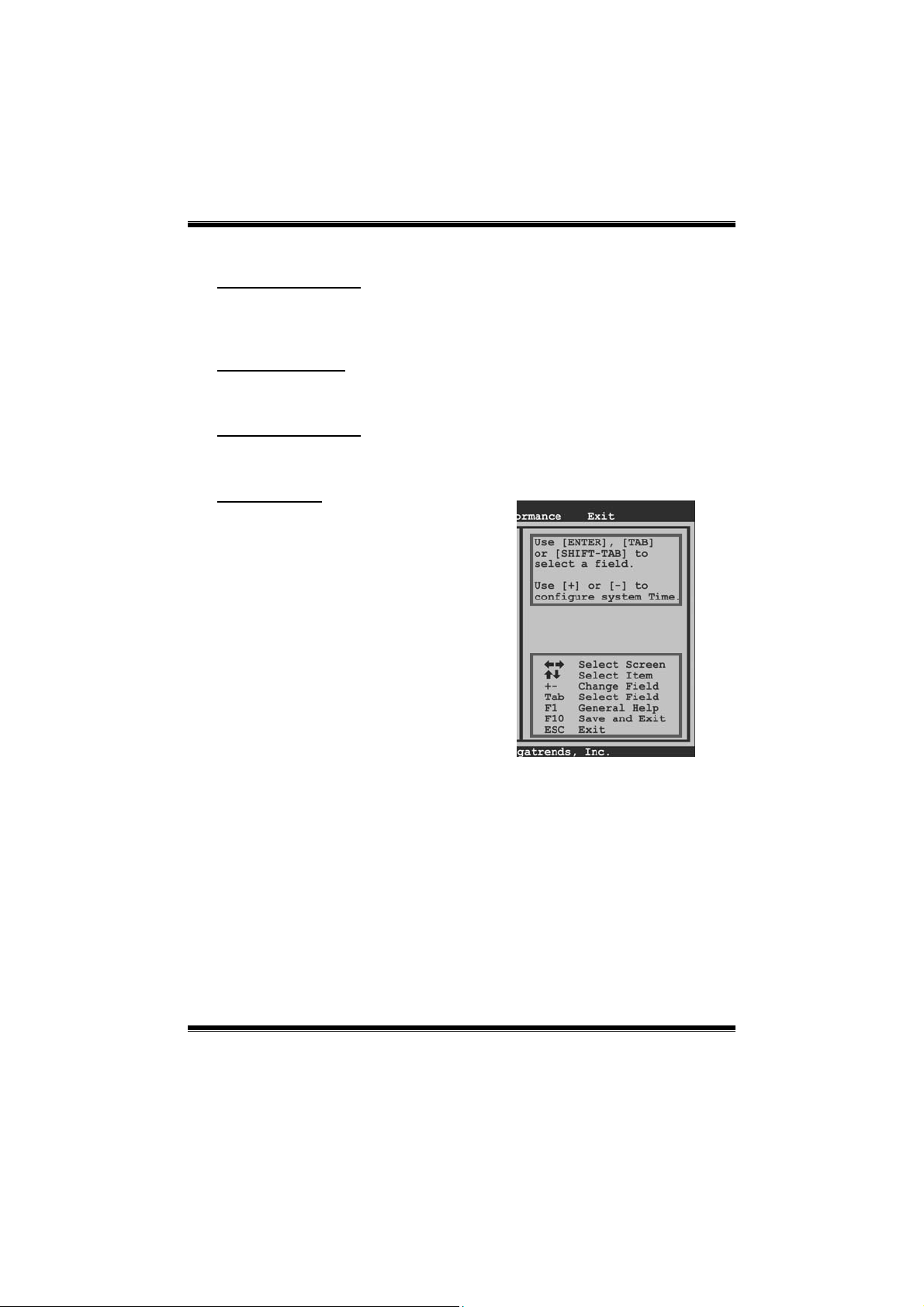
Using Setup
Whe n starting up the co mputer, press
<Del> during the Power-On Self-Test
(POST) to enter the BIOS s etup utility.
In the BIOS setup utility, you will see
General Help description at the top right
corner, and this is providing a brief
descriptio n of the selected item.
Navigation Keys for that particular menu
are at the bottom right corner, and you can
use these keys to select it em and c hange
the settings.
Notice
z The default BIOS settings apply for most conditions to ensure optimum performance
of the motherboard. If the system becomes unstable after changing any settings,
please load the default settings to ensure sys tem’s co mpatibility and stability. Use
Load Setup Default under the Exit Menu.
z For better sys tem p erfo rmance, the BIOS firmwar e is b eing continuo us ly upd ated.
The BIOS information described in this manual is for your reference only. The actual
BIOS information and settings on board may be slightly different from this manual.
z The content of this manual is subject to b e changed without not ice. W e wi ll not be
responsib le fo r any mistakes found in this user’s manual and any system damage that
may b e c aused b y wro ng-settings.
General Help
Navigation Keys
2
Page 4
TA780G M2+/TA780G M2+ HP BIOS Manual
1 Main Menu
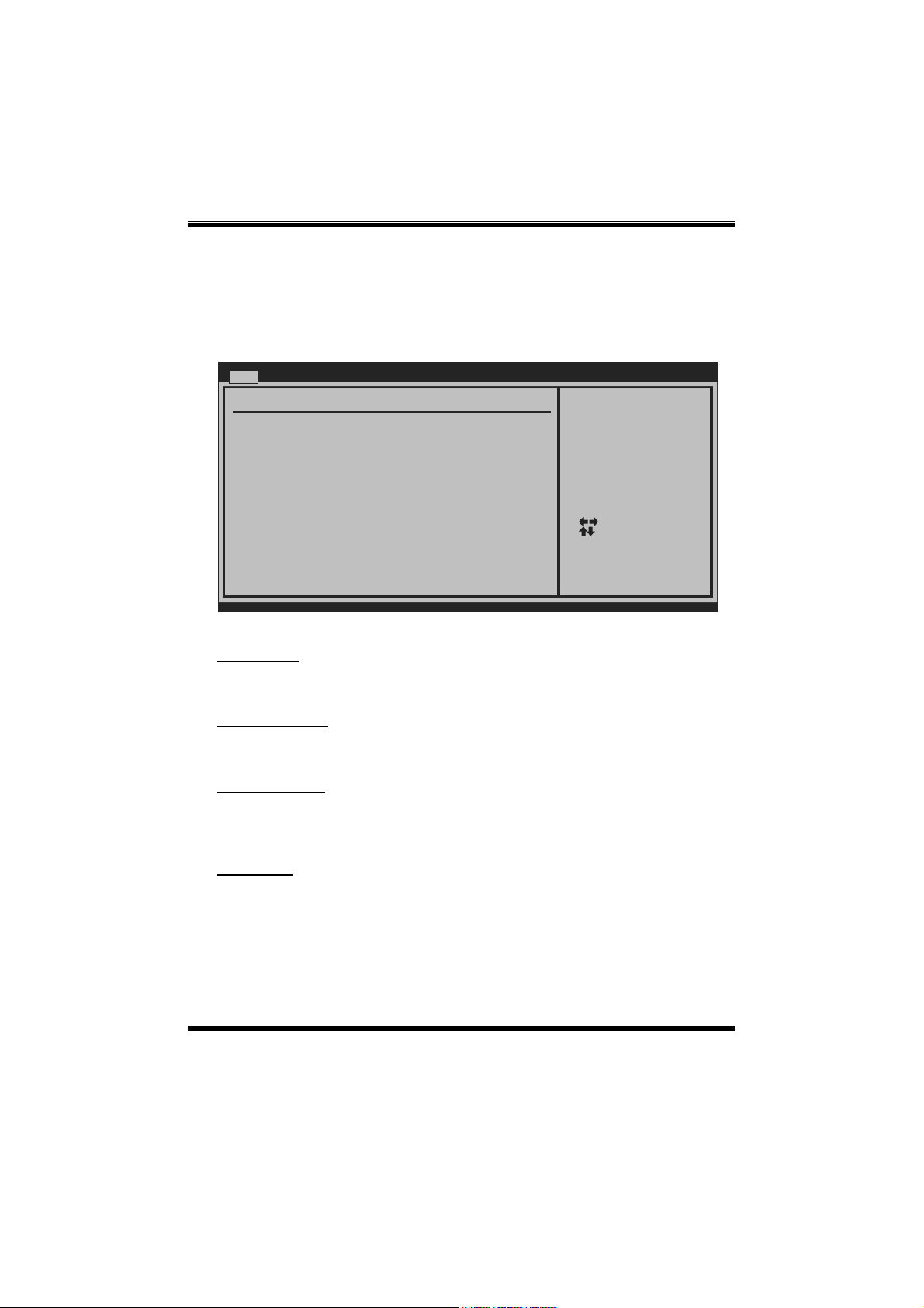
Once you enter AMI BIOS Setup Utility, the Main Menu will appear on the screen
providing an overview of the basic s ystem information.
Main Advanced PCIPnP Boot Chipset T-Series
System Overview
AMI BIOS
Version :01.01.01
Build Date:01/01/08
System Time 00
System Date [Tue 01/01/2008]
Floppy A
> IDE Configuration
vxx.xx (C)Copyright 1985-200x, American Megatrends, Inc.
AMI BIOS
Shows system information including BIOS version and built date.
BIOS SETUP UTILITY
[ :00:00]
Exit
Use [ENTER], [TAB]
or [SHIFT-TAB] to
select a field.
Use [+] or [-] to
configure system Time.
Select Screen
Select Item
+-
Change Field
Tab
Select Field
F1
General Help
F10
Save and Exit
ESC
Exit
System Time
Set t he syst em inter nal c loc k.
System Date
Set the system date. Note that the ‘Day’ automatically changes when you set the
date.
Floppy A
Select the type of flopp y disk d rive installed in your system.
Optio ns: 360 K, 5. 25 in / 1.2M, 5.25 in / 720K, 3. 5 in / 1.44M, 3.5 in /
2.88M, 3.5 in / None
3
Page 5
TA780G M2+/TA780G M2+ HP BIOS Manual
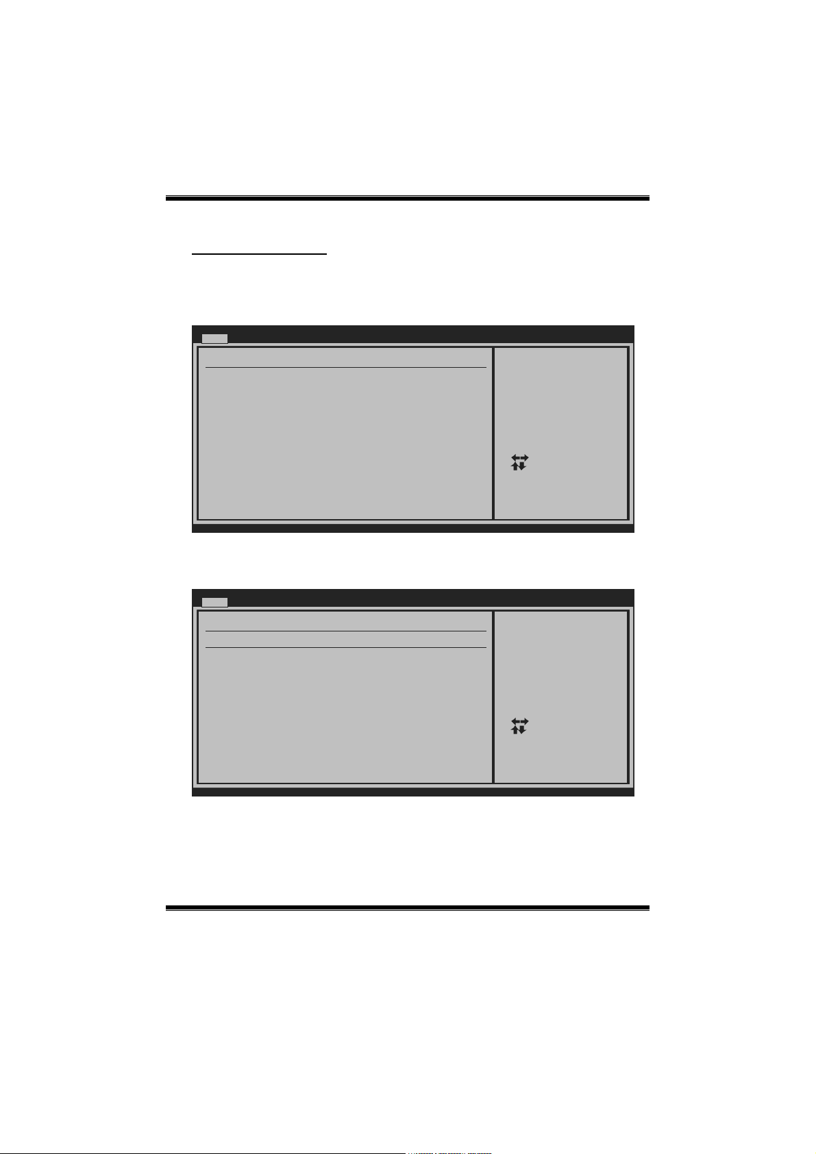
IDE Configuration
The BIOS will automat ically detect the presence of IDE/SATA devic es. T here is a
sub-menu for each IDE/SATA device. Select a devic e and press <Enter> to enter
the sub-menu of detailed options.
Main
IDE Confuguration
> Primary IDE Master
> Primary IDE Slave
> SATA 1 Device
> SATA 2 Device
> SATA 3 Device
> SATA 4 Device
> SATA 5 Device
> SATA 6 Device
Hard Disk Write Protect [Disabled]
IDE Detect Time Out (Sec) [35]
BIOS SETUP UTILITY
While entering setup,
BIOS auto detects the
presence of IDE
devices. This displays
the status of auto
detection of IDE
devices.
Select Screen
Select Item
Go to Sub Screen
Enter
General Help
F1
Save and Exit
F10
Exit
ESC
vxx.xx (C)Copyright 1985-200x, American Megatrends, Inc.
Primary IDE Master/Slave ; SATA 1/2/3/4/5/6 Device
Main
Primary IDE Master
Device :
Type [Auto]
LBA/Large Mode [Auto]
Block (Multi-Sector Transfer)[Auto]
PIO Mode [Auto]
DMA Mode [Auto]
S.M.A.R.T [Auto]
32Bit Data Transfer [Enabled]
vxx.xx (C)Copyright 1985-200x, American Megatrends, Inc.
BIOS SETUP UTILITY
Select the type
of device connected
to the system.
Select Screen
Select Item
Change Option
+-
General Help
F1
Save and Exit
F10
Exit
ESC
The BIOS detects the informat ion and va lues of resp ec tive devices, and thes e
info rmat ion and values are s hown below to t he name of the sub - menu.
4
Page 6

TA780G M2+/TA780G M2+ HP BIOS Manual
Type
Select the type of the IDE/SATA drive.
Optio ns: Auto (Default) / CDROM / ARMD / Not Installed
LBA/Large Mode
Enable or disable the LBA mode.
Optio ns: Auto (Default) / Disabled
Block (Multi-Sector Transfer)
Enable or disable multi-secto r transfer.
Optio ns: Auto (Default) / Disabled
PIO Mode
Select the PIO mode.
Optio ns: Auto (Default) / 0 / 1 / 2 / 3 / 4
DMA Mode
Select the DMA mode.
Optio ns: Auto (Default) / Disabled
S.M.A.R.T
Set the Smart Monitoring, Analysis, and Reporting Technology.
Optio ns: Auto (Default) / Disabled / Enabled
32Bit Data Transfer
Enable or disable 32-bit data transfer.
Optio ns: Enabled (Default ) / Disab led
Hard Disk Write Protect
Disab le or enable device write protec tion. T his will be effective only if the device
is acc essed thro ug h BIOS.
Optio ns: Disabled (Default) / Enabled
IDE Detect Time Out (Sec)
Select the time out value for detecting IDE/SATA devices.
Optio ns: 35 (Default) / 30 / 25 / 20 / 15 / 10 / 5 / 0
5
Page 7
TA780G M2+/TA780G M2+ HP BIOS Manual
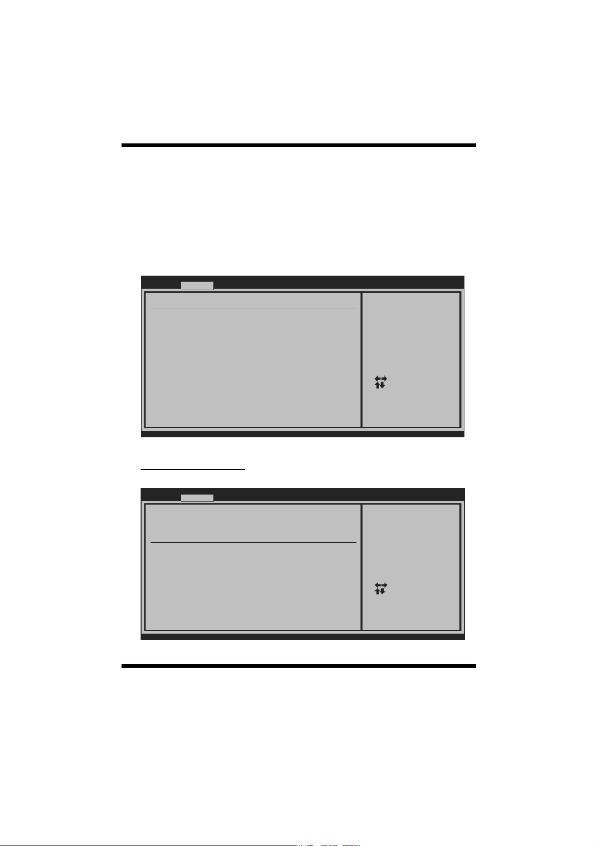
2 Advanced Menu
The Advanced Menu allows you to configure the settings of CPU, Super I/O, Power
Management, and other system devic es.
Notice
z Beware of that setting inappropriate values in items of this menu may cause
system to malfunction.
Main Advanced PCIPnP Boot Chipset T-Series
WARNING: Setting wrong values in below sections
may cause system to malfunction.
> CPU Configuration
> SuperIO Co nfiguration
> Smart F an Configuration
> Hardware Health Configuration
> ACPI Configuration
> USB Configuration
MPS Revision [1.4]
BIOS SETUP UTILITY
Configure CPU.Advanced Settings
Select Screen
Select Item
Go to Sub Screen
Enter
General Help
F1
Save and Exit
F10
Exit
ESC
Exit
vxx.xx (C)Copyright 1985-200x, American Megatrends, Inc.
CPU Configuration
This item shows the CPU informatio n that the BIOS automatically detects.
Advanced
CPU Configuration
Module Version:
AGESA Version:
Physical Count:
Logical Count:
AMD CPU
Revision:
Cache L1:
Cache L2:
Cache L3:
Speed :
Current FSB Multiplier:
Maximum FSB Multiplier:
Able to Change Freq :
uCode Patch Level :
Secure Virtual Machine Mode [Enabled]
PowerNow [Enabled]
ACPI SRAT Table [Enabled]
vxx.xx (C)Copyright 1985-200x, American Megatrends, Inc.
BIOS SETUP UTILITY
6
Enable/Disable
Secure Virtual Machine
Mode (SVM)
+F1
F10
ESC
Select Screen
Select Item
Change Option
General Help
Save and Exit
Exit
Page 8

TA780G M2+/TA780G M2+ HP BIOS Manual
Secure Virtual Machine Mode
Virt ualization Technolo gy c an virtually sepa rate your system reso urc e into several
parts, thus enhance the performance when running virtual machines or multi
interface systems.
Optio ns: Enabled (Default ) / Disab led
PowerNow
This item allows you to enable or disable the PowerNow power saving technology.
Optio ns: Enabled (Default ) / Disab led
ACPI SRAT Table
The oper at ing system sc ans the ACP I SRAT at boo t time and us es the infor mation to
bett er allocate memory and sc hedule softwar e thr eads for maximum perfo rmance.
This item controls whether the SRAT is made available to the operating system at
boot up, or not.
Optio ns: Enabled (Default ) / Disab led
SuperIO Configuration
Advanced
Configure ITE8718 Super IO Chipset
Onboard Floppy Controller [Enabled]
Serial Port1 Address [3F8/IRQ4]
Parallel Port Address [378]
Parallel Port Mode [Normal]
Parallel Port IRQ [IRQ7]
Keyboard PowerOn [Disabled]
Mouse PowerOn [Disabled]
BIOS SETUP UTILITY
Allows BIOS to Enable
or Disable Floppy
Controller
Select Screen
Select Item
Change Option
+-
General Help
F1
Save and Exit
F10
Exit
ESC
vxx.xx (C)Copyright 1985-200x, American Megatrends, Inc.
Onboard Floppy Controller
Select enabled if your system has a floppy disk controller (FDC) installed on the
system board and you wish to use it. If you installed another FDC or the system uses
no floppy drive, select disabled in this field.
Optio ns: Enabled (Default ) / Disab led
7
Page 9

TA780G M2+/TA780G M2+ HP BIOS Manual
Serial Port1 Address
Select an address and corresponding interrupt for the first and second serial ports.
Optio ns: 3F8/IRQ 4 (Default) / 2F8/IRQ3 / 3E8/IRQ4 / 2E8/IRQ3 / Auto / Disabled
Parallel Port Address
This item allows you to determine access onboard parallel port controller with which
I/O Addres s.
Optio ns: 378 (Default) / 278 / 3BC / Disabled
Parallel Port Mode
This item allows you to determine how the paralle l port sho uld function.
Options: Normal (Default) Using Parallel port as Standard Printer Port.
EPP Using Parallel Port as Enhanced Parallel Port.
ECP Using Parallel port as Extended Capabilit ies Port.
ECP+EPP Using Parallel port as ECP & EPP mode.
Parallel Port IRQ
This item allows you to select the IRQ for the onboard parallel port.
Optio ns: IRQ7 (Default) / IRQ5 / Disabled
Keyboard PowerOn
This item allows you to control the keyboard power on funct ion.
Optio ns: Disabled (Default) / Enabled
Mouse PowerOn
This item allows you to control the mouse power on functio n.
Optio ns: Disabled (Default) / Enabled
8
Page 10

TA780G M2+/TA780G M2+ HP BIOS Manual
Smart Fan Configuration
Advanced
Smart Fan Configuration
CPU Smart Fan [Disabled]
Smart Fan Calibration
Control Mode
Fan Ctrl OFF( C)
Fan Ctrl On( C)
Fan Ctrl Start value
Fan Ctrl Sensitive
o
o
BIOS SETUP UTILITY
When you choice [Auto]
,[3Pin] or [ 4Pin],
please run the
calibration to define
the Fan p arameters for
Smart Fan control
Select Screen
Select Item
Change Option
+-
General Help
F1
Save and Exit
F10
Exit
ESC
vxx.xx (C)Copyright 1985-200x, American Megatrends, Inc.
CPU Smart Fan
This item allows you to control the CPU Smart Fan function.
Optio ns: Disabled (default) / Auto / 4-pin / 3-pin
Smart Fan Calibration
Choose this item and then the BIOS will auto test and detect the CPU/System fan
functions and show CPU/System fan speed.
Control Mode
This item provides several operation modes of the fan.
Optio ns: Quiet / Performance / Manual
Fan Ctrl OFF(℃)
If the CP U/Sys tem Tempera ture is lower than the s et value, FAN wil l turn off.
Optio ns: 0~127 (℃)
Fan Ctrl On(℃)
CPU/Syst em fan starts to work under smart fan function when arrive this set value.
Optio ns: 0~127 (℃)
9
Page 11

TA780G M2+/TA780G M2+ HP BIOS Manual
Fan Ctrl Start Value
When CPU/System temperature arrives to the set value, the CPU/System fan will
work und er Smart Fan Function mod e.
Optio ns: 0~127 (℃)
Fan Ctrl Sensitive
Incr easing the value will rais e the sp eed o f CPU/System fan.
Optio ns: 1~127
Hardware Health Configuration
This item shows the system t emp erature, fan speed, a nd vo lt age information.
Advanced
Hardware Health Configuration
H/W Health Function [Enabled]
SYS
Temperature
CPU Temperature
CPU FAN Speed
CPU Core
+1.10V
+3.30V
+5.00V
+12.0V
DDR Voltage
HT Voltage
5VSB
VBAT
vxx.xx (C)Copyright 1985-200x, American Megatrends, Inc.
H/W Health Function
If yo u co mputer contains a monitoring system, it will sho w PC health status during
POST stage.
Optio ns: Enabled (Default ) / Disab led
BIOS SETUP UTILITY
Enables Hardware
Health Monitoring
Device.
Select Screen
Select Item
Change Option
+-
General Help
F1
Save and Exit
F10
Exit
ESC
10
Page 12
TA780G M2+/TA780G M2+ HP BIOS Manual
ACPI Configuration
Advanced
ACPI Settings
Suspend mode [S1 (POS)]
ACPI Version Features [ACPI v1.0]
ACPI APIC support [Enabled]
AMI OEMB table [Enabled]
Headless mode [Disabled]
> Power
BIOS SETUP UTILITY
Select the ACPI
state used for
System Suspend.
Select Screen
Select Item
Change Option
+-
General Help
F1
Save and Exit
F10
Exit
ESC
vxx.xx (C)Copyright 1985-200x, American Megatrends, Inc.
Suspend mode
The item allows you to select the suspend typ e under the ACPI operating system.
Options: S1 (POS) (Default) Power on Suspend
S3 (STR) Suspend to R AM
S1 & S3 POS+ST R
ACPI Version Features
The it em allows yo u to selec t the vers ion of ACP I.
Options: ACPI v1.0 (Default) / ACPI v2.0
ACPI APIC supp ort
This item is used to enable or dis able the motherboard's APIC (Advanced
Programmable Interrupt Contro ller). The APIC provides multip rocessor s upport,
more IRQs and faster interrupt handling.
Optio ns: Enabled (Default ) / Disab led
AMI OEMB table
Set this value to allo w the ACPI BIOS to add a pointer to an OEMB t able in the Root
System Description Table (RSDT) table.
Optio ns: Enabled (Default ) / Disab led
11
Page 13

TA780G M2+/TA780G M2+ HP BIOS Manual
Headless mode
This is a server-specific feature. A headless server is one that operates without a
keyboard, monitor or mouse. To run in headless mode, both BIOS and operating
system (e.g. Windows Server 2003) must support headless operation.
Optio ns: Disabled (Default) / Enabled
Power
Advanced
Restore on AC Power Loss [Last State]
RTC Resume [Disabled]
vxx.xx (C)Copyright 1985-200x, American Megatrends, Inc.
BIOS SETUP UTILITY
Enable/Disable SMI
based power management
and APM support.
Select Screen
Select Item
Change Option
+-
General Help
F1
Save and Exit
F10
Exit
ESC
Restore on AC Power Loss
This setting sp ecifies how your system should behave after a power fail or interrupts
occurs. By choosing Disabled will leave the computer in the power off state.
Choos ing Enabled will restore the system to the status before power failure or
interrupt occ urs.
Optio ns: Last State (Default) / Disabled
RTC Resume
When “Enabled”, you can set the date and time at which the RTC (real-time clock)
alarm awakens the system from Suspend mode.
Optio ns: Disabled (Default) / Enabled
12
Page 14

TA780G M2+/TA780G M2+ HP BIOS Manual
USB Configuration
This item shows the USB contro ller and using USB device information.
Advanced
USB Configuration
Module Version - 2.24.2-13.4
USB Devices Enabled:
Legacy USB Support [Enabled]
USB 2.0 Controller Mode [HiSpeed]
BIOS EHCI Hand-Off [Enabled]
> USB Mass Storage Device Configuration
BIOS SETUP UTILITY
Enables support for
legacy USB. AUTO
option disables
legacy support if
no USB devices are
connected.
Select Screen
Select Item
Change Option
+-
General Help
F1
Save and Exit
F10
Exit
ESC
vxx.xx (C)Copyright 1985-200x, American Megatrends, Inc.
Legacy USB Support
This item determines if the BIOS should provide legacy support for USB devic es
like the keyboard, mouse, and USB drive. This is a useful feature when using such
USB devices with operating sys tems that do not natively support USB (e.g.
Microsoft DOS or Windows NT).
Optio ns: Enabled (Default ) / Disab led
USB 2. 0 Con troller Mode
This item allows you to select the operation mode of the USB 2.0 co ntro ller.
Options: HiSpeed (Default) USB 2.0-480Mbps
FullSpeed USB 1.1-12Mbps
BIOS EHCI Hand -Off
This item allows you to enable suppo rt for operating systems witho ut an EHCI
hand-off feature.
Optio ns: Enabled (Default ) / Disab led
13
Page 15

TA780G M2+/TA780G M2+ HP BIOS Manual
USB Mass Storage Device Configuration
Advanced
USB Mass Storage Device Configuration
USB Mass Storage Reset Delay [20 Sec]
Device #
Emulation Type [Auto]
vxx.xx (C)Copyright 1985-200x, American Megatrends, Inc.
BIOS SETUP UTILITY
Number of seconds
POST waits for the
USB mass storage
device after start
unit command.
Select Screen
Select Item
Change Option
+-
General Help
F1
Save and Exit
F10
Exit
ESC
USB Mass Storage Reset Delay
This item allows you to set the reset delay for USB mass sto rage device.
Options: 20 Sec (Default) / 10 Sec / 30 Sec / 40 Sec
Emulation Type
This item allows you to select the emulation type of the USB mass storage device.
Optio ns: Auto (Default) / Flopp y / Forc ed FDD / Hard Dis k / CDROM
MPS Version
The BIOS supports version 1.1 and 1.4 of the Intel multiprocessor specification.
Selec t vers io n s uppor ted by t he operat ion sys te m running on th is co mputer.
Optio ns: 1.4 (Defau lt) / 1.1
14
Page 16

TA780G M2+/TA780G M2+ HP BIOS Manual
3 PCIPnP Menu
This section describes configuring the PCI bus system. PCI, or Personal Computer
Interconnect, is a syste m which allo ws I/O devic es to operate at sp eeds near ing the
speed of the CPU itself uses when communicating with its own special components.
Notice
z Beware of that setting inappropriate values in items of this menu may cause
system to malfunction.
Main Advanced PCIPnP Boot Chipset T-Series
Advanced PCI/PnP Settings
WARNING: Setting wrong values in below sections
may cause system to malfunction.
Clear NVRAM [No]
Plug & Play O/S [No]
PCI Latency Timer [64]
Allocate IRQ to PCI VGA [Yes]
Palette Snooping [Disabled]
PCI IDE BusMaster [Enabled]
> PCI Resource
> PCI Express Configuration
BIOS SETUP UTILITY
Clear NVRAM during
System Boot.
Select Screen
Select Item
Change Option
+-
General Help
F1
Save and Exit
F10
Exit
ESC
Exit
vxx.xx (C)Copyright 1985-200x, American Megatrends, Inc.
Clear NVRAM
This item allows you to clear the data in the NVRAM (CMOS) by selecting “Yes”.
Options: No (Default) / Yes
Plug & Play OS
When set to YES, BIOS will o nly initialize the PnP cards us ed for the boot sequence
(VGA, IDE, SCSI). The rest of the cards will be initialized by the PnP operating
system like Windo w™ 95. When set to NO, BIOS will initialize all the PnP cards.
For non-PnP operating systems (DOS, Netware™), this option must set to NO.
Options: No (Default) / Yes
15
Page 17

TA780G M2+/TA780G M2+ HP BIOS Manual
PCI Latency Timer
This item co ntrols how long a PCI device can hold th e PC I bus before another takes
over. The longer the latency, the longer the PCI device can retain control of the bus
before handing it over to another PCI device.
Optio ns: 64 ( Default) / 0-255
Allocate IRQ to PCI VGA
This item allows BIOS to choos e a IRQ to assign for the PCI VGA card.
Optio ns: Yes (Default) / No
Palett e Snooping
Some old grap hic contro llers ne ed to “snoop” on the VGA palette and then map it to
their display as a way to provide boot information and VGA compatibility. This item
allows such snooping to take place.
Optio ns: Disabled (Default) / Enabled
PCI IDE BusMast er
This item is a toggle for the built-in driver that allows the onboard IDE controller to
perform DMA (Direc t Memory Acc ess) trans fers.
Optio ns: Enabled (Default ) / Disab led
PCI Resource
PCIPnP
PCI Resource
IRQ3 [Available]
IRQ4 [Available]
IRQ5 [Available]
IRQ7 [Available]
IRQ9 [Available]
IRQ10 [Available]
IRQ11 [Available]
IRQ14 [Available]
IRQ15 [Available]
DMA Channel 0 [Available]
DMA Channel 1 [Available]
DMA Channel 3 [Available]
DMA Channel 5 [Available]
DMA Channel 6 [Available]
DMA Channel 7 [Available]
Reserved Memory Size [Disabled]
vxx.xx (C)Copyright 1985-200x, American Megatrends, Inc.
BIOS SETUP UTILITY
16
Available: Specified
IRQ is available to be
used by PCI/PnP
devices.
Reserved: Specified
IRQ is reserved for
use by Legacy ISA
devices.
Select Screen
Select Item
Change Option
+-
General Help
F1
Save and Exit
F10
Exit
ESC
Page 18

TA780G M2+/TA780G M2+ HP BIOS Manual
IRQ3/4/5/7/9/10/11/14/15
Thes e items will allow you to assign each sys tem inter rup t a type, depending on the
type o f devic e using the in terrupt. The optio n “Avai lab le” means t he IRQ is go ing
to ass ign auto matically.
Optio ns: Available (Default)
DMA Channel 0/1/3/5/6/7
These items will allow you to assign each DMA channel a type, depending on the
type o f devic e us ing the channel. The op t ion “Available” means the channe l is
going to assign auto matically.
Optio ns: Available (Default)
Reserved Memory Size
This item allows BIOS to reserve certain memory size for specif ic PCI device.
Optio ns: Disabled (Default) / Enabled
PCI Express Configuration
PCIPnP
PCI Express Configuration
Active State Power-Management[Disabled]
BIOS SETUP UTILITY
Enable/Disable
PCI Express L0s and
L1 link power
states.
Select Screen
Select Item
Change Option
+-
General Help
F1
Save and Exit
F10
Exit
ESC
vxx.xx (C)Copyright 1985-200x, American Megatrends, Inc.
Active State Power-Management
This item sets the ASPM configuration for the PCI Express devic es before the
operating system boots. This function is for OS which does not support ASPM.
Optio ns: Disabled (Default) / Enabled
17
Page 19

TA780G M2+/TA780G M2+ HP BIOS Manual
4 Boot Menu
This menu allo ws you to setup the s ys tem boo t options.
Main A dvanced PCIPnP Boot Chipset T-Series
Boot Settings Configuration
> Boot Device Priority
> Hard Disk Drives
> Removable Drives
> CD/DVD Drives
Quick Boot [Enabled]
Full Screen LOGO Show [Disabled]
AddOn ROM Display Mode [Force BIOS]
Bootup Num-Lock [ON]
Interrupt 19 Capture [Enabled]
BIOS SETUP UTILITY
Exit
Specifies the
Boot Device
Priority sequence.
Select Screen
Select Item
Go to Sub Screen
Enter
General Help
F1
Save and Exit
F10
Exit
ESC
vxx.xx (C)Copyright 1985-200x, American Megatrends, Inc.
Boot Device Priority
Items in this s ub-menu specify the boot device priority sequence from the available
devices. The number of device items that appears on the screen depends on the
number of devices ins talled in the system.
Optio ns: Removable / Hard Disk / CDROM / Legacy LAN / Disabled
Hard Disk Drives
The BIOS will attempt to arrange the hard disk boot sequence automatically. You
can also change the booting sequence. The numb er of device items that appears on
the screen depends on the number of devices installed in the system.
Optio ns: Pri. Master / Pri. Slave / Sec. Master / Sec. Slave / USB HDD0 /
USB HDD1 / USB HDD2 / Bootable Add-in Cards
Removable Drives
The BIOS will attempt to arrange the removable drive boot sequenc e automatically.
You can also ch ange t he boo t ing sequenc e. T he numb er of device items that
appears on the screen depends on the number of devices installed in the system.
Options: Floppy Disks / Zip100 / USB-FDD0 / USB-FDD1 / USB-ZIP0 /
USB-ZIP1 / LS120
18
Page 20

TA780G M2+/TA780G M2+ HP BIOS Manual
CD/DVD Drives
The BIOS will attempt to arrange the CD/DVD drive boo t seq uence automatically.
You can also ch ange t he boo t ing sequenc e. T he numb er of device items that
appears on the screen depends on the number of devices installed in the system.
Optio ns: Pri. Mas ter / Pri. Slave / Sec. Mas ter / S ec. S lave / US B CDROM0 /
USB CDROM 1
Quick Boot
Enabling this option will cause an abridged version of the Power On Self-Test
(POS T) to execute after you power up the computer.
Optio ns: Enabled (Default ) / Disab led
Full Screen LOGO Show
This item allows you to enable/disable Full Screen LOGO Show function.
Optio ns: Disabled (Default) / Enabled
AddOn ROM Display Mode
This item sets the display mode for op tion ROM.
Options: Force BIOS (Default) / Keep Current
Bootup Num-Lock
Selec ts the NumLoc k State after the system s witched on.
Options: ON (Default) / OFF
Interrupt 19 Capture
When set to Enabled, this item allows the option ROMs to trap inter rupt 19.
Optio ns: Enabled (Default ) / Disab led
19
Page 21

TA780G M2+/TA780G M2+ HP BIOS Manual
5 Chipset Menu
This submenu allows you to configure the specific features of the chipset installed on
your system. This chipset manage bus speeds and access to system memory
resources, such as DRAM. It also coordinates communications with the PCI bus.
Main A dvanced PCIPnP Boot Chipset T-Series
> SouthBridge Configuration
> RS780 C onfiguration
> OnBoard Pe ripherals Configuration
BIOS SETUP UTILITY
Options for NBAdvanced Chipset Settings
Select Screen
Select Item
Go to Sub Screen
Enter
General Help
F1
Save and Exit
F10
Exit
ESC
Exit
vxx.xx (C)Copyright 1985-200x, American Megatrends, Inc.
SouthBridge Configuration
BIOS SETUP UTILITY
> SB Azalia Audio Configuration
OHCI HC(Bus 0 Dev 18 Fn o) [Enabled]
OHCI HC(Bus 0 Dev 18 Fn 1) [Enabled]
EHCI HC(Bus 0 Dev 18 Fn 2) [Enabled]
OHCI HC(Bus 0 Dev 19 Fn 0) [Enabled]
OHCI HC(Bus 0 Dev 19 Fn 1) [Enabled]
EHCI HC(Bus 0 Dev 19 Fn 2) [Enabled]
OHCI HC(Bus 0 Dev 20 Fn 5) [Enabled]
OnChip SATA Channel [Enabled]
OnChip SATA Type [Native IDE]
SATA IDE Combined Mode [Enabled]
Combined Mode Option [SATA as primary]
SB CIM Version
vxx.xx (C)Copyright 1985-200x, American Megatrends, Inc.
Chipset
20
Options for SB HD Azal
Select Screen
Select Item
Go to Sub Screen
Enter
General Help
F1
Save and Exit
F10
Exit
ESC
Page 22

TA780G M2+/TA780G M2+ HP BIOS Manual
SB Azalia Audio Configuration
BIOS SETUP UTILITY
HD Audio Azalia Device [Enabled]
HD Onboard PIN Config [Enabled]
Azalia Front Panel [Auto]
SDIN0 Pin Config [Azalia]
SDIN1 Pin Config [Azalia]
SDIN2 Pin Config [Azalia]
SDIN3 Pin Config [Azalia]
Azalia Snoop [Disabled]
vxx.xx (C)Copyright 1985-200x, American Megatrends, Inc.
Chipset
Options
Auto
Disabled
Enabled
Select Screen
Select Item
Change Option
+-
General Help
F1
Save and Exit
F10
Exit
ESC
HD Audio Azalia Device
This item allows you to control the HD audio device.
Optio ns: Enabled (Default ) / Disab led
HD Onboard PIN Config
This item allows you to configure the pin definition of the onboard HD header.
Optio ns: Enabled (Default ) / Disab led
Azalia Front Panel
This item controls the HD front panel header function.
Optio ns: Auto (Default) / Disabled
SDIN0/1/2/3 Pin Config
Options: Azalia (Default) / AC’97
Azalia Snoop
This item controls the HD snoop func tion.
Optio ns: Disabled (Default) / Enabled
OHCI HC(Bus 0 Dev 18/19/20 Fn 0/1/5)
Optio ns: Enabled (Default ) / Disab led
21
Page 23

TA780G M2+/TA780G M2+ HP BIOS Manual
EHCI HC(Bus 0 Dev 18/19 Fn 2)
Optio ns: Enabled (Default ) / Disab led
OnChip SATA Channel
This optio n allows you to enable the o n-c hip Serial ATA.
Optio ns: Enabled (Default ) / Disab led
OnChip SATA Type
This optio n allows you to select the on-chip S erial ATA operation mode.
Optio ns: Native IDE (Default) / RAID / AHCI / Legacy IDE / IDEÆAHCI
SATA IDE C ombined Mode
This optio n contro ls the SATA/P ATA co mbined mod e.
Optio ns: Enabled (Default ) / Disab led
Combined Mode Option
This item allows you to set the SATA/PATA combined mod e.
Optio ns: SATA as p rimary (Default) / IDE as primary
RS780 Configuration
BIOS SETUP UTILITY
RS780 Configuration
> Internal G raphics Configuration
> PCI Express Configuration
Primary Video Controller [PCI-GFX0-GPP-IGFX]
NB Power Management Features [Auto]
vxx.xx (C)Copyright 1985-200x, American Megatrends, Inc.
Chipset
22
Internal Graphics Conf
Select Screen
Select Item
Go to Sub Screen
Enter
General Help
F1
Save and Exit
F10
Exit
ESC
Page 24

TA780G M2+/TA780G M2+ HP BIOS Manual
Internal Graphics Configuration
BIOS SETUP UTILITY
Internal Graphics Configuration
Internal Graphics Mode [UMA]
UMA Frame Buffer Size [Auto]
GFX Engine Clock Override [Disable]
GFX Engine Clock [500]
Surround View [Disabled]
FB Location [Above 4G]
NB Azalia [Enable]
> Debug O ption
vxx.xx (C)Copyright 1985-200x, American Megatrends, Inc.
Chipset
Options
Disable
UMA
SIDEPORT
UMA+SIDEPORT
Select Screen
Select Item
Change Option
+-
General Help
F1
Save and Exit
F10
Exit
ESC
Internal G rap hi cs Mod e
This item allows you to select the memory mode used for internal graphics device.
Opt io ns: UMA (Def a u lt) / SIDEP ORT / UMA+ SIDEPORT / Dis ab le
UMA Frame Buffer Size
This item allows you to choose the UMA frame buffer size for internal graphics.
Options: Auto (Default) / 16M / 32M / 64M / 128M / 256M / 512M / Disabled
GFX Engine Clock Override
This item allows you to control the internal GFX engine clock override function.
Optio ns: Disabled (Default) / Enabled
GFX Engine Clock
This item allows you to set the internal GFX engine clock.
Optio ns: 500 (Default)
Surround View
This item allows you to control the Surround View Function.
Options: Disabled (Default)
FB Location
This item allows you to set the FB-DIMM location.
Options: Above 4G (Default) / Under 4G
23
Page 25

TA780G M2+/TA780G M2+ HP BIOS Manual
NB Azalia
This item allows you to control the northbridge HD azalia function.
Optio ns: Enabled (Default ) / Disab led
Debug Option
BIOS SETUP UTILITY
Bank Mapping Control [Auto]
UMA Address Swizzle Control [Auto]
VBIOS Type [Auto]
Chipset
Options
Auto
Manual
Select Screen
Select Item
Change Option
+-
General Help
F1
Save and Exit
F10
Exit
ESC
vxx.xx (C)Copyright 1985-200x, American Megatrends, Inc.
Bank Mapping Control
Options: Auto (Default) / Manual
UMA Addres s Sw izzle Control
Options: Auto (Default) / Manual
VBI OS Typ e
Options: Auto (Default) / Manual
24
Page 26

TA780G M2+/TA780G M2+ HP BIOS Manual
PCI Express Configuration
BIOS SETUP UTILITY
PCI Express Configuration
GPP Slots Power Limit, W [25 ]
> Port #04 Features
> Port #07 Features
> NB-SB P ort Features
vxx.xx (C)Copyright 1985-200x, American Megatrends, Inc.
GPP Slots Power Limit, W
Optio ns: 25 ( Default) / 0-255
Port #04/07 Features
BIOS SETUP UTILITY
Gen2 High Speed Mode [Disabled]
Link ASPM [Disabled]
Chipset
Chipset
Select Screen
Select Item
Update
Enter
General Help
F1
Save and Exit
F10
Exit
ESC
Auto - RC only
advertize Gen2
capability.
vxx.xx (C)Copyright 1985-200x, American Megatrends, Inc.
Gen2 High Speed Mode
Options: Disabled (Default) / So ftware Switc h / Autonomous Awitch
Link A SPM
Options: Disabled (Default) / L0s / L1 / L0x & L1
25
Select Screen
Select Item
Change Option
+-
General Help
F1
Save and Exit
F10
Exit
ESC
Page 27

TA780G M2+/TA780G M2+ HP BIOS Manual
NB-SB Port F eatures
BIOS SETUP UTILITY
NB-SB Link ASPM [Disabled]
NP NB-SB VC1 Traffic Support [Disabled]
Link Width [Auto]
Chipset
Options
Disabled
L1
Select Screen
Select Item
Change Option
+-
General Help
F1
Save and Exit
F10
Exit
ESC
NB- SB Li n k ASP M
vxx.xx (C)Copyright 1985-200x, American Megatrends, Inc.
Options: Disabled (Default) / L1
NP NB-SB VC1 Traffic Support
Options: Disabled (Default) / Enabled
Link Width
Options: Auto (Default) / 8bit / 16bit
Primary Video Controller
This optio n allows you to s elect the video controller in charge.
Opt io ns: PCI-GF X0-GPP -IGF X (Def a u lt)
NB Power Management Fea tures
This option controls the NB power management function.
Optio ns: Auto (Default) / Disabled
26
Page 28

TA780G M2+/TA780G M2+ HP BIOS Manual
OnBoard Peripherals Configuration
BIOS SETUP UTILITY
Realtek PCIE NIC [Enable]
Realtek Option ROM [Disabled]
Chipset
Enable/Disable
Onboard Broadcom
PCIE Network
Controller
Select Screen
Select Item
Change Option
+-
General Help
F1
Save and Exit
F10
Exit
ESC
vxx.xx (C)Copyright 1985-200x, American Megatrends, Inc.
Realtek PCIE NIC
This optio n allo ws you to contro l the onboard LAN controller.
Optio ns: Enable (Default) / Disable
Realtek Option ROM
This item allo ws yo u to enab le or disable the Onbo ard LAN Boot ROM.
Optio ns: Disabled (Default) / Enabled
27
Page 29

TA780G M2+/TA780G M2+ HP BIOS Manual
6 T-Series Menu
This submenu allo ws you to change volt age and clock o f var ious devices.
(However, we suggest you to use the def ault s ett ing. Changing t he voltage and c lock
improperly may damage the device.)
Notice
z Beware of that setting inappropriate values in items of this menu may cause
system to malfunction.
Main Advanced PCIPnP Boot Chipset T-Series
T-Series Settings
WARNING: Setting wrong values in below sections
may cause system to malfunction.
OverClock Navigator [Normal]
=========== Automate OverClock System ===========
Auto OverClock System [V6-Tech Engine]
============ Manual OverClock System ============
CPU Overvoltage [StartUp]
Memory Overvoltage [1.95V]
Chipset Overvoltage [1.15V]
HT Overvoltage [1.20V]
CPU Frequency [200]
> Memory Configuration
> DRAM Timing Configuration
> Hyper T ransport Configuration
Integrated Memory Test [Disabled]
vxx.xx (C)Copyright 1985-200x, American Megatrends, Inc.
BIOS SETUP UTILITY
Options
Normal
Automate OverClock
Manual OverClock
Select Screen
Select Item
Change Option
+-
General Help
F1
Save and Exit
F10
Exit
ESC
Exit
OverClock Na vigator
OverClock .Navigator is designed for beginners in overclock field.
Based on many test and experiments from Biostar Engineer Team, OverClock
Navigator provides 3 default overclock configurations that are able to raise the
system performance.
Options: Normal (Default) / Automate OverClock / Manual OverClock
28
Page 30

TA780G M2+/TA780G M2+ HP BIOS Manual
Auto OverClock System
Main Advanced PCIPnP Boot Chipset T-Series
T-Series Settings
WARNING: Setting wrong values in below sections
may cause system to malfunction.
OverClock Navigator [Automate OverClock]
=========== Automate OverClock System ===========
Auto OverClock System [V6-Tech Engine]
============ Manual OverClock System ============
CPU Overvoltage [StartUp]
Memory Overvoltage [1.95V]
Chipset Overvoltage [1.15V]
HT Overvoltage [1.20V]
CPU Frequency [200]
> Memory Configuration
> DRAM Timing Configuration
> Hyper T ransport Configuration
Integrated Memory Test [Disabled]
vxx.xx (C)Copyright 1985-200x, American Megatrends, Inc.
BIOS SETUP UTILITY
Options
Normal
Automate OverClock
Manual OverClock
Select Screen
Select Item
Change Option
+-
General Help
F1
Save and Exit
F10
Exit
ESC
Exit
The Ove rc lock Navigator provides 3 dif f erent engines help ing you to overclock your
system. These engines will boost your system performance to different level.
Options:
V6 Tech Engine
This engine will make a good over-clock performanc e.
V8 Tech Engine
This engine will make a better over-clock performance.
V12 T ech Engine
This engine will make a best over-clock performance.
Cautions:
1. Not every AMD CPU performs the above overclock setting ideally; the difference may vary
with the insta lle d C P U mode l.
2. Fr om BET experim ent, the Atholo n 64 FX CP U is not suit able for this A.O. S. fe ature .
29
Page 31

TA780G M2+/TA780G M2+ HP BIOS Manual
Manual Overclock System (M.O.S.)
Main Advanced PCIPnP Boot Chipset T-Series
T-Series Settings
WARNING: Setting wrong values in below sections
may cause system to malfunction.
OverClock Navigator [Manual OverClock]
=========== Automate OverClock System ===========
Auto OverClock System [V6-Tech Engine]
============ Manual OverClock System ============
CPU Overvoltage [StartUp]
Memory Overvoltage [1.95V]
Chipset Overvoltage [1.15V]
HT Overvoltage [1.20V]
CPU Frequency [200]
> Memory Configuration
> DRAM Timing Configuration
> Hyper T ransport Configuration
Integrated Memory Test [Disabled]
vxx.xx (C)Copyright 1985-200x, American Megatrends, Inc.
BIOS SETUP UTILITY
MOS is designed for experienced overclock users.
It allows users to c ustomize personal overclock setting.
CPU Overvoltage
This item allows you to select CPU Voltage Contro l.
Optio ns: StartUp (Default)
Memory O vervoltag e
This item allows you to select DDR Volt age Control.
Options: 1.95V (Default) / 2.00V / 2.05V / 2.10V
Exit
Options
Normal
Automate OverClock
Manual OverClock
Select Screen
Select Item
Change Option
+-
General Help
F1
Save and Exit
F10
Exit
ESC
Chipset Overvoltage
This item allows you to select NB/S B Voltage Control.
Optio ns: 1.15V (Default) / 1.20V / 1.25V / 1.30V / 1.35V / 1.40V
HT Overvoltage
This item allows you to select HT Voltage Control.
Optio ns: 1.20V (Default) / 1.25V / 1.30V / 1.35V / 1.40V
30
Page 32

TA780G M2+/TA780G M2+ HP BIOS Manual
CPU Frequency
This item allows you to select the CPU Frequency.
Options: 200 (MHz) (Default) / 200-600
Memory Configuration
BIOS SETUP UTILITY
Memory Configuration
Bank Interleaving [Auto]
Channel Interleaving [XOR of Address bit]
Enable Clock to All DIMMs [Disabled]
MemClk Tristate C3/ATLVID [Disabled]
Memory Hole Remapping [Enabled]
DCT Unganged Mode [Always]
Power Down Enable [Enabled]
Power Down Mode [Channel]
> ECC Configuration
vxx.xx (C)Copyright 1985-200x, American Megatrends, Inc.
T-Series
Enable Bank Memory
Interleaving
+F1
F10
ESC
Select Screen
Select Item
Change Option
General Help
Save and Exit
Exit
Bank Interleaving
Bank Interlea ving is an advanced chipset technique used to impro ve memo ry
performance. Memory interleaving incre ases bandwid th by allowin g simu ltaneo us
access to more than one piece of memory.
Optio ns: Auto (Default)
Channel Interleavin g
This item allows you to control the DDR2 dual-channel func tion.
Options: XOR of Address bit (Default)
Enable Clock to All DIMMs
This item determines whether the BIOS should act ively reduce EMI
(Electromagnetic Interference) and reduce power consumption by turning off
unocc upied or inac tive DIM M slots.
Optio ns: Disabled (Default) / Enabled
31
Page 33

TA780G M2+/TA780G M2+ HP BIOS Manual
MemClk Tristate C3/ATLVID
This item enables or disables the MemClk Tristate function in C3 Mode.
Optio ns: Disabled (Default) / Enabled
Memory Hole Remapping
This item allows you to enable or dis able the remapping of the overlapped PCI
memory above the total physical memory. Only 64-bit OS supports this function.
Optio ns: Enabled (Default ) / Disab led
DCT Unganged Mode
This item controls the DRAM controller ganged (128bit*1) / unganged (64bit*2)
dual-channel operation mode. If two DRAM modules with different size are
installed, using unganged mode can still make it run in dual-channel operatio n.
Options: Always (Default) / Ganged / Unganged
Power Down Enable
This item controls the DRAM power down function.
Optio ns: Enabled (Default ) / Disab led
Power Down Mode
This item allows you to select the DRAM power do wn mode.
Optio ns: Channel (Default) / CS
32
Page 34

TA780G M2+/TA780G M2+ HP BIOS Manual
ECC Configuration
BIOS SETUP UTILITY
ECC Configuration
ECC Mode [Disabled]
DRAM ECC Enable [Disabled]
DRAM SCRUB REDIRECT [Disabled]
4-Bit ECC Mode [Disabled]
DRAM BG Scrub [Disabled]
Data Cache BG Scrub [Disabled]
L2 Cache BG Scrub [Disabled]
L3 Cache BG Scrub [Disabled]
vxx.xx (C)Copyright 1985-200x, American Megatrends, Inc.
T-Series
Set the level of ECC
protection. Note: The
Super ECC mode
dynamically sets the
DRAM scrub rate so
all of memory is
scrubbed in 8 hours.
Select Screen
Select Item
Change Option
+-
General Help
F1
Save and Exit
F10
Exit
ESC
ECC Mode
This item allows you to select the DRAM ECC Mode.
Optio ns: Disabled (Default) / Basic / Good / Super / Max / User
DRAM ECC Enabled
Optio ns: Disabled (Default) / Enabled
DRAM Scrub Redirect
Optio ns: Disabled (Default) / Enabled
4-bit ECC Mode
Optio ns: Disabled (Default) / Enabled
DRAM BG Scrub/Data Cache BG Scrub/L2 Cache BG Scrub/L3 Cache BG Scrub
Options: Disabled (Default) / 40ns / 80ns / 160ns / 320ns / 640ns / 1.28us / 2.56us /
5.12us / 10.2us / 20.5us / 41.0us / 81.9us / 163. 8us / 327. 7us / 655.4us
33
Page 35

TA780G M2+/TA780G M2+ HP BIOS Manual
DRAM Timing Configuration
BIOS SETUP UTILITY
DRAM Timing Configuration
Memory Clock Mode [Auto]
Memclock Value [200 MHz]
DRAM Timing Mode [Auto]
Memory CLK
CAS Latency(Tcl)
RAS/CAS Delay(Trcd)
Row Precharge Time(Trp)
Min Active RAS(Tras)
RAS/RAS Delay(Trrd)
Row Cycle (Trc)
vxx.xx (C)Copyright 1985-200x, American Megatrends, Inc.
T-Series
Select the DRAM
Frequency programming
method. If A uto,
the DRAM speed will
be based on SPDs.
If Limit, the DRAM spe
will not exceed the
specified value. If
Manual, the DRAM speed
specified will be
programmed regardless.
Select Screen
Select Item
Change Option
+-
General Help
F1
Save and Exit
F10
Exit
ESC
Memory Clock Mode
This item allows you to control the Memory Clock.
Optio ns: Auto (Default) / Manual
Memclock Value
This item allows you to set the Memory Clock.
Options: 200MHz (Default) / 266MHz / 333MHz / 400MHz / 533MHz
DRAM Timing Mode
This item allo ws you to choose to manually or automatically regulate the DRAM
Timing.
Optio ns: Auto (Default) / MaxMemClk
34
Page 36

TA780G M2+/TA780G M2+ HP BIOS Manual
Hyper Transport Configuration
BIOS SETUP UTILITY
Hyper Transport Configuration
NODE0:PCI-X2 HT Link
Link Speed [Auto]
Link Width [Auto]
vxx.xx (C)Copyright 1985-200x, American Megatrends, Inc.
T-Series
The Hypertransport
link will run at this
speed if it is slower
than or equal to the
system clock and the
board is capable.
Select Screen
Select Item
Change Option
+-
General Help
F1
Save and Exit
F10
Exit
ESC
Link Speed
Options: Auto (Default) / 200MHz / 400MHz / 600MHz / 800MHz / 1GHz
Link Wid th
Optio ns: Auto (Default) / 8 Bit / 16 Bit
35
Page 37

TA780G M2+/TA780G M2+ HP BIOS Manual
Integrated Memory Test
Integrated Memory Test allows users to test memory module co mpatibilit ies witho ut
additional device or software.
Step 1:
This item is dis abled on default; change it to “ Enable” to preced e memory test.
Main Advanced PCIPnP Boot Chipset T-Series
T-Series Settings
WARNING: Setting wrong values in below sections
may cause system to malfunction.
OverClock Navigator [Normal]
=========== Automate OverClock System ===========
Auto OverClock System [V6-Tech Engine]
============ Manual OverClock System ============
CPU Overvoltage [StartUp]
Memory Overvoltage [1.95V]
Chipset Overvoltage [1.15V]
HT Overvoltage [1.20V]
CPU Frequency [200]
> Memory Configuration
> DRAM Timing Configuration
> Hyper T ransport Configuration
Integrated Memory Test [Enabled]
vxx.xx (C)Copyright 1985-200x, American Megatrends, Inc.
BIOS SETUP UTILITY
Options
Normal
Automate OverClock
Manual OverClock
Select Screen
Select Item
Change Option
+-
General Help
F1
Save and Exit
F10
Exit
ESC
Exit
Step 2:
When the process is done, change the setting back from “Enabled” to “Disabled” to
complete the test.
Main Advanced PCIPnP Boot Chipset T-Series
T-Series Settings
WARNING: Setting wrong values in below sections
may cause system to malfunction.
OverClock Navigator [Normal]
=========== Automate OverClock System ===========
Auto OverClock System [V6-Tech Engine]
============ Manual OverClock System ============
CPU Overvoltage [StartUp]
Memory Overvoltage [1.95V]
Chipset Overvoltage [1.15V]
HT Overvoltage [1.20V]
CPU Frequency [200]
> Memory Configuration
> DRAM Timing Configuration
> Hyper T ransport Configuration
Integrated Memory Test [Disabled]
vxx.xx (C)Copyright 1985-200x, American Megatrends, Inc.
BIOS SETUP UTILITY
36
Options
Normal
Automate OverClock
Manual OverClock
Select Screen
Select Item
Change Option
+-
General Help
F1
Save and Exit
F10
Exit
ESC
Exit
Page 38

TA780G M2+/TA780G M2+ HP BIOS Manual
7 Exit Menu
This menu allows you to load the optimal default settings, and save or disc ard the
changes to the BIOS items.
Main Advanced PCIPnP Boot Chipset T-Series
Exit Options
Save Changes and Exit
Discard Changes and Exit
Discard Changes
Load Optimal Defaults
Security Settings
> Security
BIOS SETUP UTILITY
Exit
Exit system setup
after saving the
changes.
F10 key can be used
for this operation.
Select Screen
Select Item
Go to Sub Screen
Enter
General Help
F1
Save and Exit
F10
Exit
ESC
vxx.xx (C)Copyright 1985-200x, American Megatrends, Inc.
Save Changes and Exit
Save all configuration changes to CMOS RAM and exit setup.
Discard Changes and Exit
Abandon all changes made d uring the current session and exit setup.
Discard Changes
Abandon all changes made during the current session and restore the previously
saved values.
Load Optimal Defaults
This s election allo ws you to reload t he BIOS when problem occ urs during sys tem
booting sequence. These configuratio ns are factory settings optimized for this
system.
37
Page 39

TA780G M2+/TA780G M2+ HP BIOS Manual
Security
This sub-menu allows you to provide/revise supervisor and user password.
Security Settings
Supervisor Password :Not Installed
User Password :Not Installed
Change Supervisor Password
Change User Password
Boot Sector Virus Protection [Disabled]
BIOS SETUP UTILITY
Exit
Install or Change the
password.
Select Screen
Select Item
Change
Enter
General Help
F1
Save and Exit
F10
Exit
ESC
vxx.xx (C)Copyright 1985-200x, American Megatrends, Inc.
Change Supervis or Pa sswor d
Setting the supervisor p ass word will prohib it everyone except the supervisor from
making changes using the CMOS Set up Utility. Yo u will be prompted with to enter a
password.
Change User Password
If the Supervisor Password is not set, then the User Password will function in the
same way as the Supervisor Password. If the Supervisor Password is set and the User
Password is set, the “ User” will only be able to view configurations but will not be
able to c hange them.
Boot Sector Virus Protection
This optio n al lows you to c hoos e the VIR US Warning fe ature that is us ed to pro t ect
the IDE Hard Disk boot sector. If this function is enabled and an attempt is made to
write to the boot sector, BIOS will display a warning message on the screen and
sound an alarm beep.
Optio ns: Disabled (Default) / Enabled
38
 Loading...