

Page 1

TA780G M2+/TA780G M2+ HP/TA760G M2+
Setup Manual
FCC Information and Copyright
This equipment has been tested and found to comply with the limits of a Class
B digital device, pursuant to Part 15 of the FCC Rules. These limits are designed
to provide reasonable protection against harmful interference in a residential
installation. This equipment generates, uses, and can radiate radio frequency
energy and, if not installed and used in accordance with the instructions, may
cause harmful interference to radio communications. There is no guarantee
that interference will not occur in a particular installation.
The vendor makes no representations or warranties with respect to the
contents here and specially disclaims any implied warranties of merchantability
or fitness for any purpose. Further the vendor reserves the right to revise this
publication and to make changes to the contents here without obligation to
notify any party beforehand.
Duplication of this publication, in part or in whole, is not allowed without first
obtaining the vendor’s approval in writing.
The content of this user’s manual is subject to be changed without notice and
we will not be responsible for any mistakes found in this user’s manual. All the
brand and product names are trademarks of their respective companies.
Page 2

Table of Contents
Chapter 1: Introduction ............................................................ 1
1.1 Before You Start ................................................................................ 1
1.2 Package Checklist............................................................................. 1
1.3 Motherboard Features...................................................................... 2
1.4 Rear Panel Connectors ..................................................................... 3
1.5 Motherboard Layout......................................................................... 4
Chapter 2: Hardware Installation ............................................. 5
2.1 Installing Central Processing Unit (CPU)....................................... 5
2.2 FAN Headers...................................................................................... 7
2.3 Installing System Memory ................................................................ 8
2.4 Connectors and Slots....................................................................... 10
Chapter 3: Headers & Jumpers Setup .................................. 12
3.1 How to Setup Jumpers .................................................................... 12
3.2 Detail Settings.................................................................................. 12
Chapter 4: RAID Functions ..................................................... 19
4.1 Operating System............................................................................ 19
4.2 Raid Arrays...................................................................................... 19
4.3 How RAID Works............................................................................. 19
Chapter 5: T-Series BIOS & Software ..................................... 22
5.1 T-Series BIOS..................................................................................... 22
5.2 T-Series Software ............................................................................. 30
Chapter 6: Useful Help ............................................................ 35
6.1 Driver Installation Note.................................................................. 35
6.2 Extra Information............................................................................ 36
6.3 Troubleshooting............................................................................... 37
Appendix: SPEC In Other Languages ...................................... 38
German.................................................................................................................. 38
French .................................................................................................................... 40
Italian..................................................................................................................... 42
Spanish ................................................................................................................... 44
Portuguese ............................................................................................................ 46
Polish...................................................................................................................... 48
Russian ................................................................................................................... 50
Arabic..................................................................................................................... 52
Japanese ................................................................................................................ 54
Page 3

TA780G M2+/TA780G M2+ HP/TA760G M2+
CHAPTER 1: INTRODUCTION
1.1 B
EFORE YOU START
Thank you for choosing our product. Before you start installing the
motherboard, please make sure you follow the instructions below:
Prepare a dry and stable working environment with
sufficient lighting.
Always disconnect the computer from power outlet
before operation.
Before you take the motherboard out from anti-static
bag, ground yourself properly by touching any safely
grounded appliance, or use grounded wrist strap to
remove the static charge.
Avoid touching the components on motherboard or the
rear side of the board unless necessary. Hold the board
on the edge, do not try to bend or flex the board.
Do not leave any unfastened small parts inside the
case after installation. Loose parts will cause short
circuits which may damage the equipment.
Keep the computer from dangerous area, such as heat
source, humid air and water.
1.2 PACKAGE CHECKLIST
HDD Cable X 1
Serial ATA Cable X 2
Serial ATA Power Cable X 1
Rear I/O Panel for ATX Case X 1
User’s Manual X 1
Fully Setup Driver CD X 1
FDD Cable X 1 (optional)
USB 2.0 Cable X1 (optional)
S/PDIF out Cable X 1 (optional)
DVI to HDMI Adapter X 1 (optional for TA780G M2+ / TA780G
M2+ HP only)
Note: The package contents may be different due to area or your motherboard version.
1
Page 4
Motherboard Manual
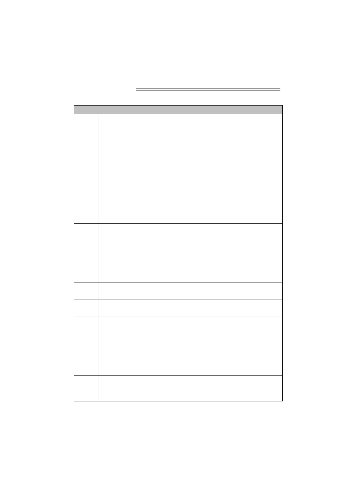
1.3 MOTHERBOARD FEATURES
Socket AM2+ / AM2
AMD Athlon 64 / Athlon 64 FX / Athlon 64 x2
CPU
FSB
Chipset
Super I/O
Main
Memory
Graphics Integrated in AMD 780G/760G Chipset
IDE Int eg r ated ID E Con tro lle r
SATA II Integrated Serial ATA Controller
LAN Realtek RTL 8111C
Sound ALC662
Slots
On Board
Connector
/ Sempron / Phenom p rocess ors
Athlon Max. Power: 125W
Pheno m Max. Power: 95W
Support HyperTransport 3.0
Supports up to 5.2 GT/s Bandwidth
AMD 780G (TA760G M2+: AMD 760G)
AMD SB700 (TA760G M2+: AMD SB710)
ITE 8718F
Prov ides the most commonly used legacy
Super I/O functionality
DDR2 DIMM Slots x 4
Max Memory Capacity 16GB
Each DIMM supports
256MB/512MB/1GB/2GB/4GB DDR2
PCI Express Gen2 x16 slot x1 Supports PCI-E Gen2 x16 expansion cards
PCI Express Gen2 x1 slot x1 Supports PCI-E Gen2 x1 expansion cards
PCI slot x2 Supports PCI expansion cards
Floppy connector x1 Each connector supports 2 Floppy drives
IDE Connector x1 Each connect or supports 2 IDE device
SATA Connect or x6 Each connect or supports 1 SATA devices
SPEC
AMD 64 Architecture enables 32 and 64 b it
computing
Supports Hyper Transport 3.0 and Cool=n=Quiet
Low Pin Count Interface
En viro nment Con tro l init iatives
H/W Mon itor
ITE's "S mart Guard ian" funct ion
Dual Channe l Mode DDR2 memory mod u le
Supports DDR2 533 / 667 / 800
Supports DDR2 1066 (for AM2+ CPU on ly)
Register ed D IMM and ECC DIMM is not support ed
Max S hared V ideo Me mo ry is 512 MB
DX10 support
DVI support
Ultra DMA 33 / 66 / 100 / 133 Bus Master Mode
supports PIO Mode 0~4,
Data transfer rates up to 3 Gb/s
SATA Vers ion 2 .0 spe cif ic at ion co mp liant
10 / 100 / 1000 Mb/s auto negotiation
Half / Full duplex capability
5.1 channels audio out
High Definition Audio
2
Page 5
TA780G M2+/TA780G M2+ HP/TA760G M2+
SPEC
Front Panel Connector x1 Supports front panel facilit ies
Front Audio Connector x1 Supports front panel audio function
CD-in Connector x1 Supports CD audio-in function
S/PDIF out connector x1 Supports digital audio out funct ion
CPU Fan header x1 CPU Fan power supply (with Smart Fan function)
System Fan head er x1 Sys tem Fan Power supply
CMOS clear header x1 Restore CMOS data to factory default
USB connect or x3 Each connector s upports 2 front panel USB ports
Power Connector (24pin) x1 Connects to Power supply
Power Connector (4pin) x1 Connects to Power supply
Printer Port Connector x1 Each connector supports 1 Printer port
Serial port Connector x1 Connects to RS-232 Port
PS/2 Keyboard x1
PS/2 Mous e x1
Back Panel
I/O
Board Size 215 mm(W) x 244 mm(L)
Special
Features
OS Support Windows XP / VISTA
DVI port x1
VGA port x1
LAN port x1
USB Port x4
Audio Jack x3
RAID 0 / 1 / 1+0 support
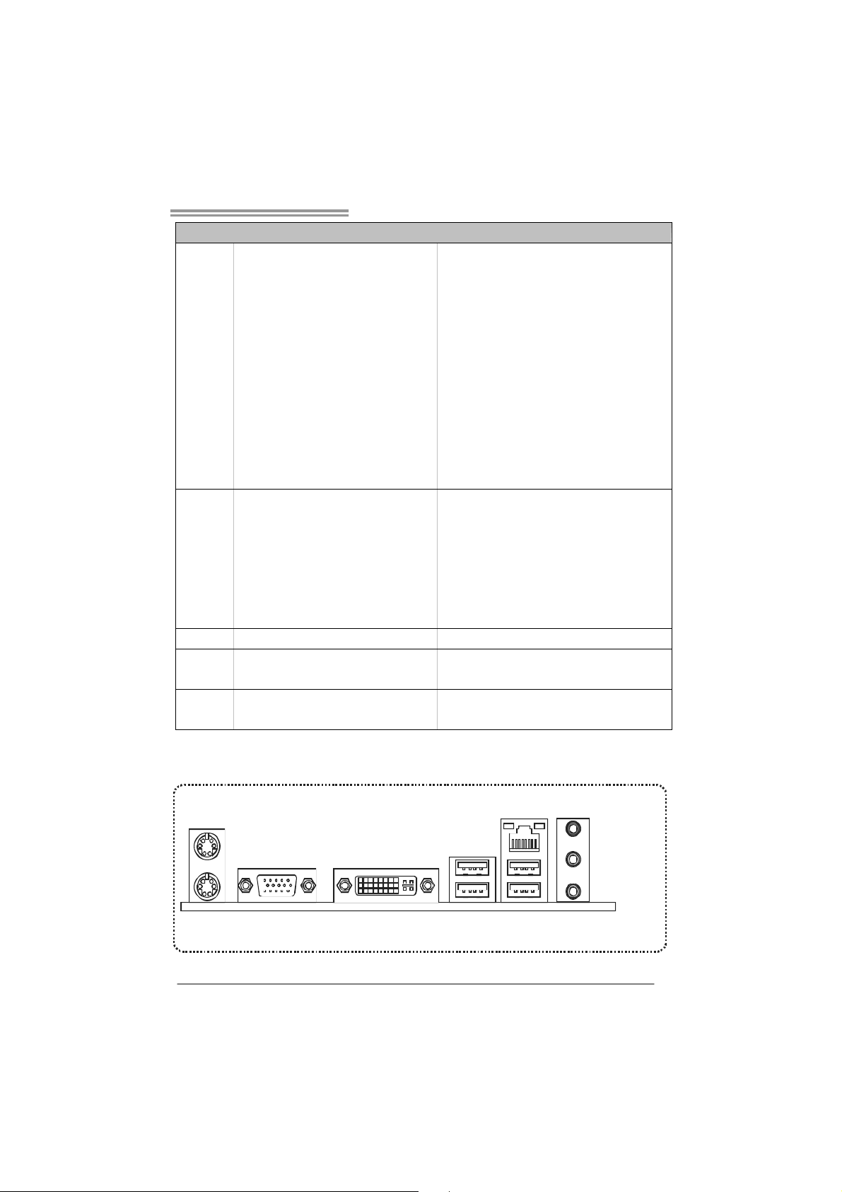
1.4 R
EAR PANEL CONNECTORS
Connects to PS/2 Keyboard
Connects to PS/2 Mouse
Connect to DVI-D monitor
Connect to D-SUB monitor
Connect to RJ-45 ethernet cable
Connect to USB dev ices
Provide Audio-In/Out and microphone connection
Biostar Reserves the right to add or remove support
for any OS With or without notice.
PS/2
Mou se
PS/2
Keyboard
LAN
Line In/
Surr ound
Line Out
Mic In 1/
Bass/ Center
VGA
DVI-D
USB X2USBX2
3
Page 6
Motherboard Manual
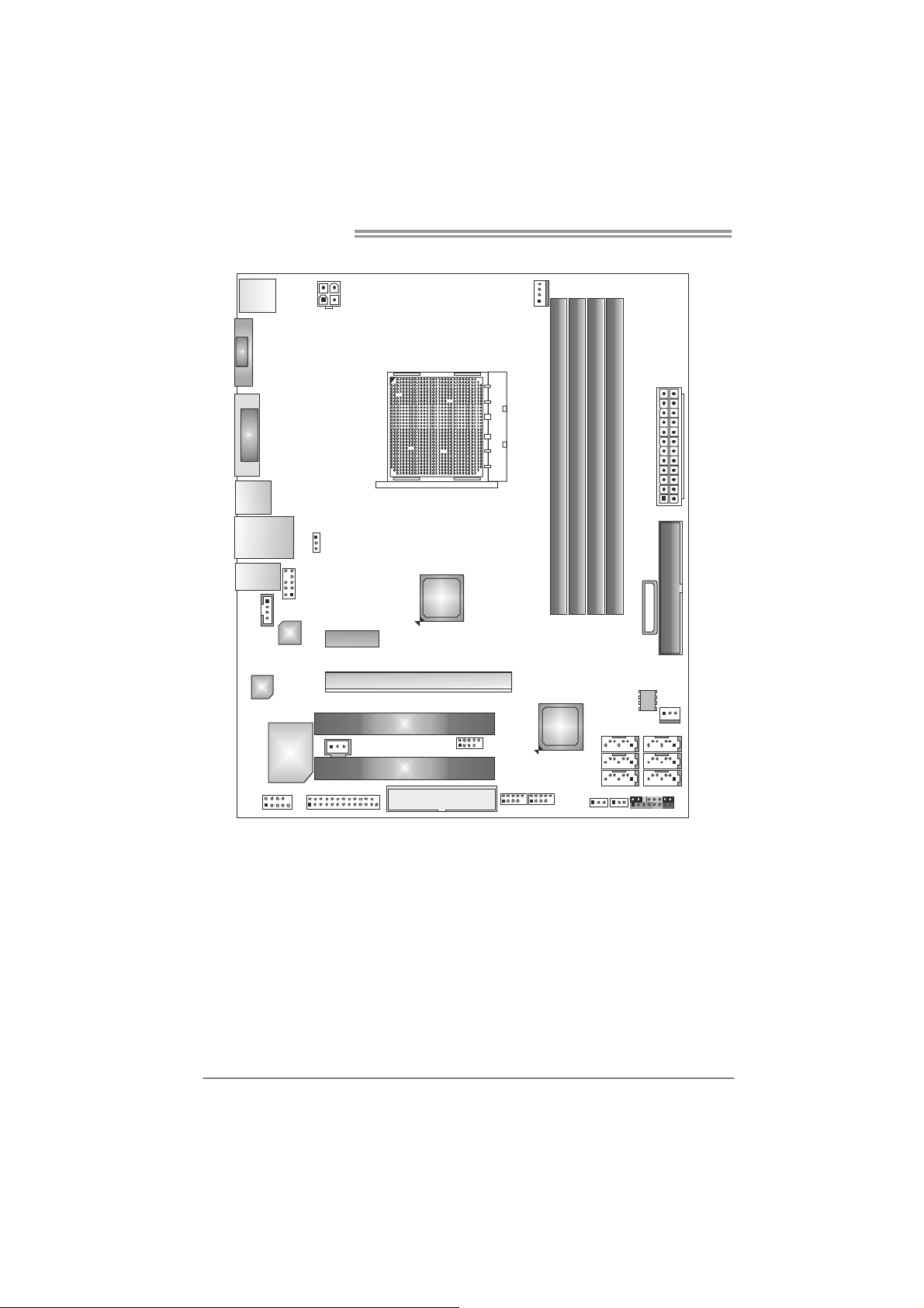
1.5 MOTHERBOARD LAYOUT
JKBMS1
JATXPWR2
VGA
JCFAN1
DVI
JUSB1
JUSBLAN 1
JAUDIO1
JAUDIOF 1
JCDIN1
LAN
Codec
Supe r I/O
JCOM1
Note: represents the 1■
JUS BV1
PEX1_1
JPRNT1
JSPDIF _OUT1
PEX16 _1
PCI1
PCI2
AMD
780G/
760G
FDD1
st
pin.
Socket AM2+
JUSB4
JUSB3 JUSB2
AMD
SB7 00/
SB 710
DIMMA1
JUSBV2
DIMMB1
SAT A3
SATA 1
DIMMA2
DIMMB2
SATA5 S ATA6
JCMOS1
JPANEL1
JATXPWR1
BATTER Y
JSFAN1
BIOS
SATA2
IDE1
SATA4
4
Page 7
TA780G M2+/TA780G M2+ HP/TA760G M2+
CHAPTER 2: HARDWARE INSTALLATION
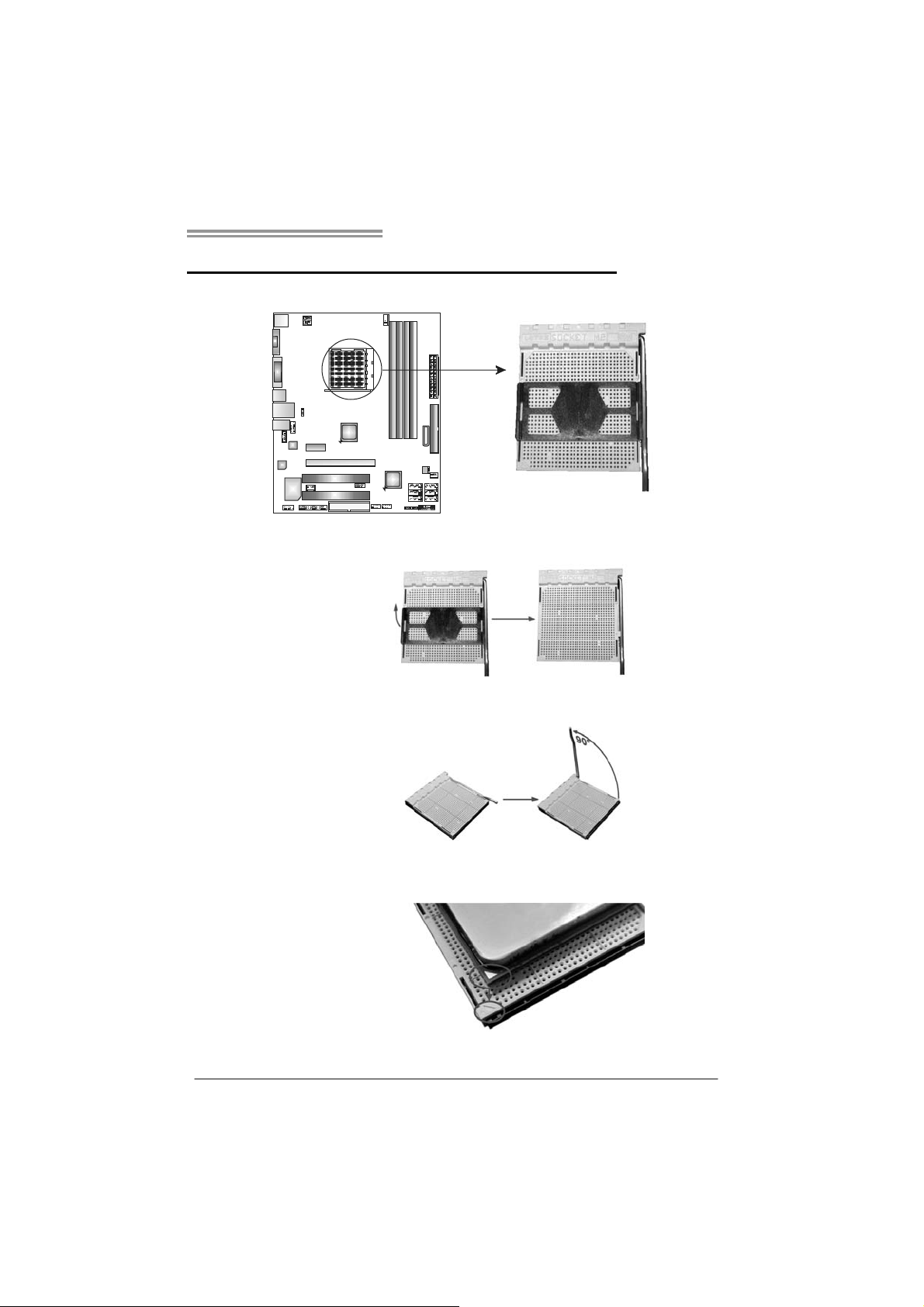
2.1 I
NSTALLING CENTRAL PROCESSING UNIT (CPU)
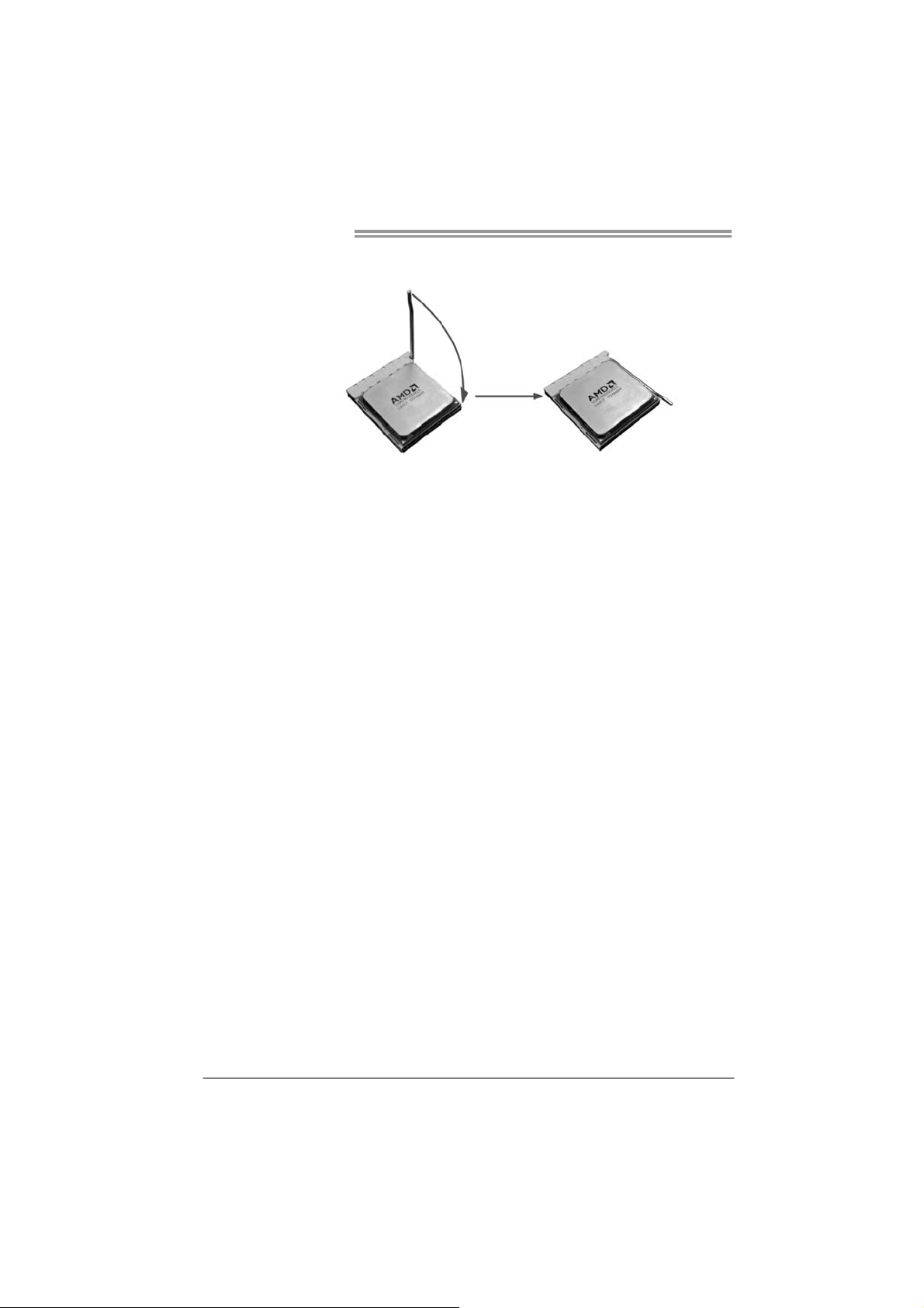
Step 1: Remove the socket protection cap.
Step 2: Pull the lever toward direction A from the socket and then raise the
lever up to a 90-degree angle.
Step 3: Look for the white triangle on socket, and the gold triangle on
CPU should point towards this white triangle. The CPU will fit only
in the correct orientation.
5
Page 8
Motherboard Manual
Step 4: Hold the CPU down firmly, and then close the lever toward direct
B to complete the installation.
Step 5: Put the CPU Fan on the CPU and buckle it. Connect the CPU
FAN power cable to the JCFAN1. This completes the installation.
Note: Please update the BIOS to the latest version while using AM2+ CPUs. Due to the latest CPU
transition, you may encounter the situation that the ne w system failed to boot while using new
AM2+ CPUs. In this case, please install one standard AM2 CPU to boot your system, and
update the latest BIOS from our website for AM2+ CPUs support.
6
Page 9
TA780G M2+/TA780G M2+ HP/TA760G M2+
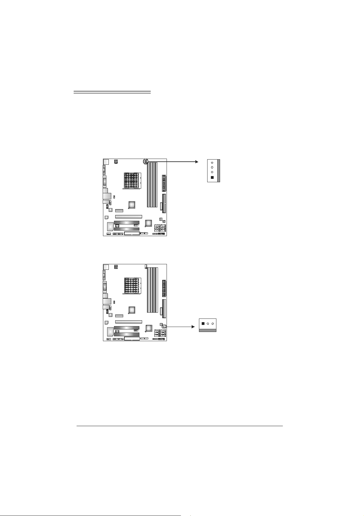
2.2 FAN HEADERS
These fan headers support cooling-fans built in the computer. The fan
cable and connector may be different according to the fan manufact urer.
Connect the fan cable to the connector while matching the black wire to
pin#1.
JCFAN1: CPU Fan Header
4
1
JSFAN1: System Fan Header
13
Pin
Assignment
1 Ground
2 +12V
3
FAN RPM r at e
sense
4 Smart Fan
Control (By Fan)
Pin
Assignment
1 Ground
2 +12V
3 FAN RPM rate
sense
Note:
The JCFAN1 supports 4-pin head connector. The JSFAN1 supports 3-pin head
connector. When connecting with wires onto connectors, please note that the red wire is
the positive and should be connected to pin#2, and the black wire is Ground and should
be connected to GND.
7
Page 10
Motherboard Manual
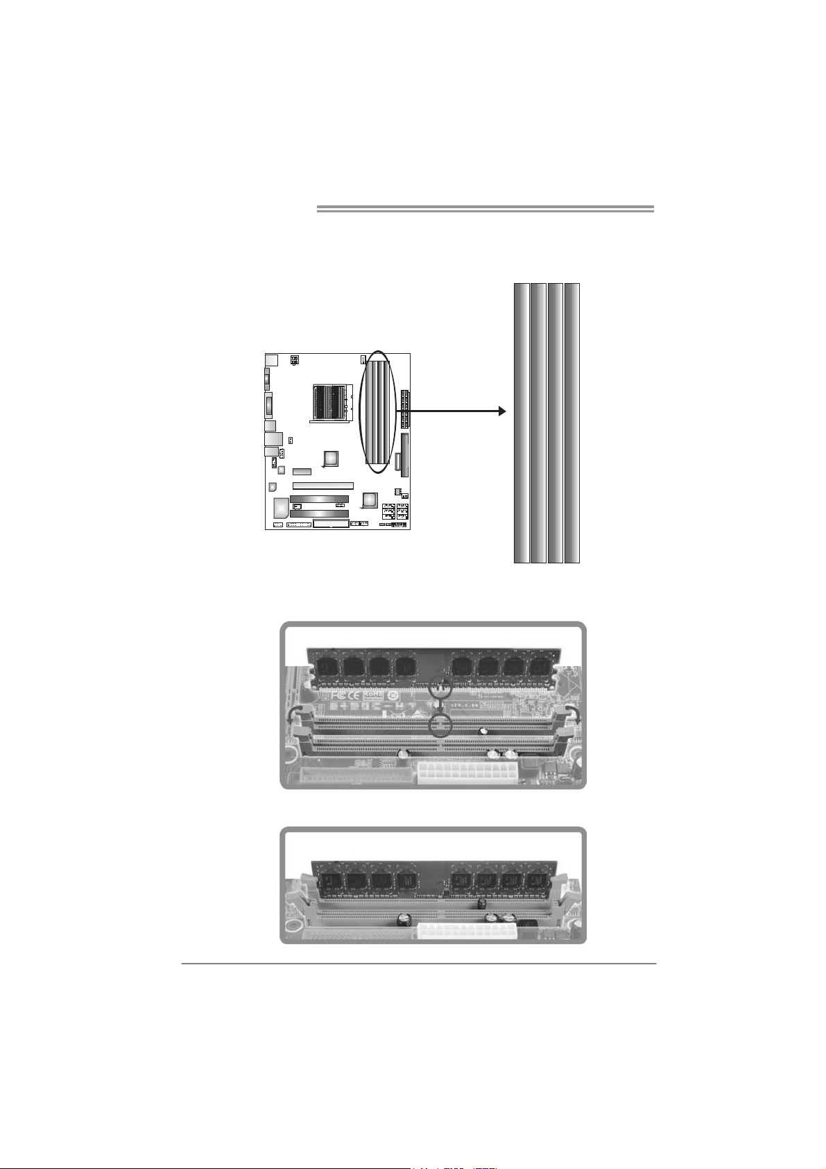
2.3 INSTALLING SYSTEM MEMORY
A. Memory Modules
DIMMB1
DIMMA1
DIMMA2
1. Unlock a DIMM slot by pressing the retaining clips outward. Align a
DIMM on the slot such that the notch on the DIMM matches the
break on the Slot.
DIMMB2
2. Insert the DIMM vertically and firmly into the slot until the retaining
chip snap back in place and the DIMM is properly seated.
8
Page 11
TA780G M2+/TA780G M2+ HP/TA760G M2+
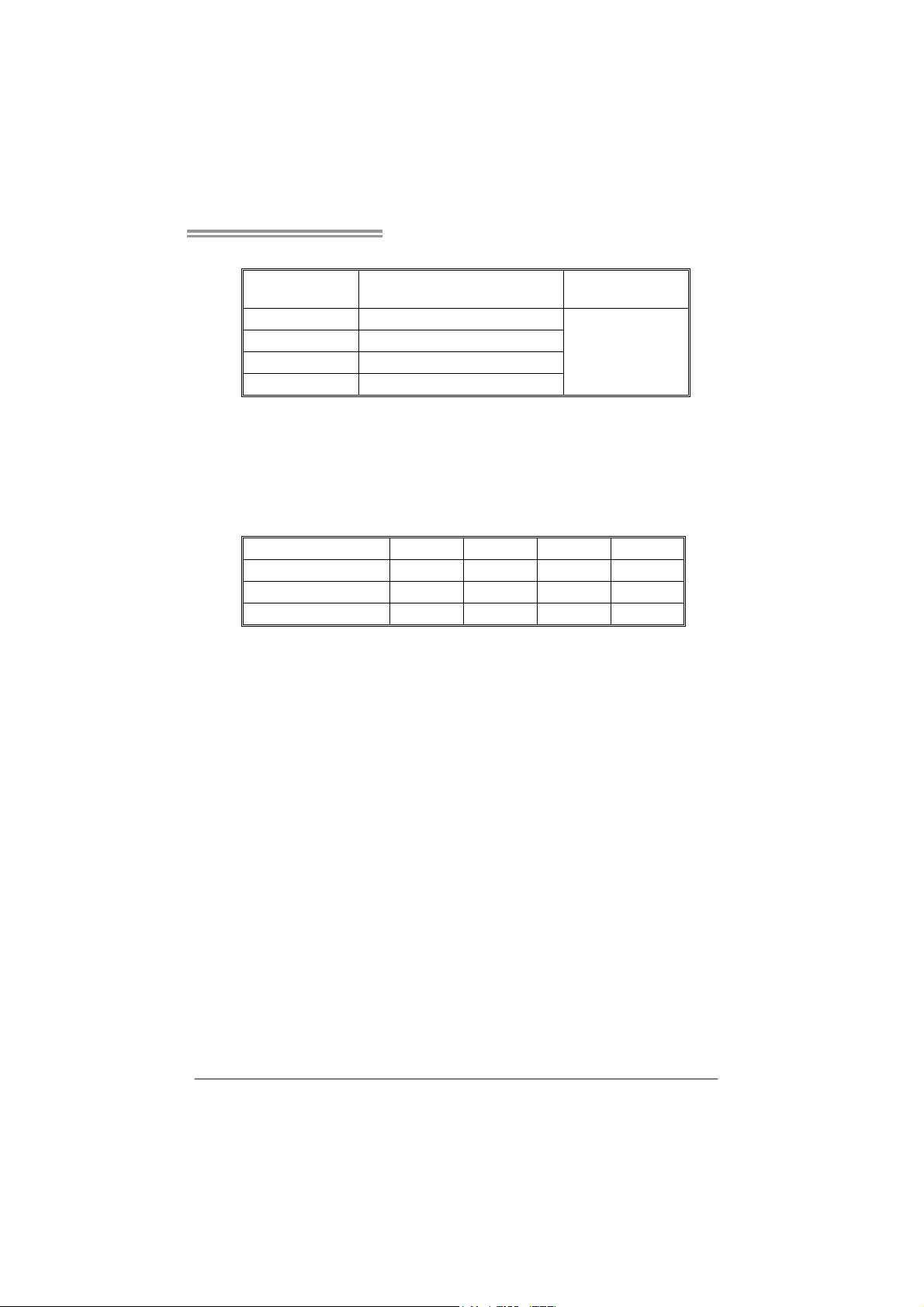
B. Memory Capacity
DIMM Socket
Location
DIMMA1 256MB/512MB/1GB/2GB/4GB
DIMMB1 256MB/512MB/1GB/2GB/4GB
DIMMA2 256MB/512MB/1GB/2GB/4GB
DIMMB2 256MB/512MB/1GB/2GB/4GB
DDR2 Module
Total Memory Size
Max is 16GB.
C. Dual Channel Memory installation
To trigger the Dual Channel function of the motherboard, the memory module
must meet the following requirements:
Install memory module of the same density in pairs, shown in the following
table.
Dual Channel Status
Enabled O O X X
Enabled X X O O
Enabled O O O O
DIMMA1
DIMMB1
(O means memory installed, X means memory not installed.)
The DRAM bus width of the memory module must be the same (x8 or
x16)
DIMMA2
DIMMB2
9
Page 12
Motherboard Manual
3
2.4 CONNECTORS AND SLOTS
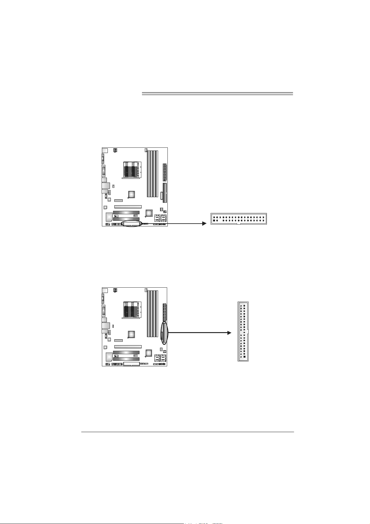
FDD1: Floppy Disk Connector
The motherboard provides a standard floppy disk connector that supports 360K,
720K, 1.2M, 1.44M and 2.88M floppy disk types. This connector supports the
provided floppy drive ribbon cable.
234
IDE1: Hard Disk Connector
The motherboard has a 32-bit Enhanced PCI IDE Controller that provides PIO
Mode 0~4, Bus Master, and Ultra DMA 33/66/100/133 functionality.
The IDE connectors can connect a master and a slave drive, so you can
connect up to two hard disk drives.
13
3940
21
10
Page 13
TA780G M2+/TA780G M2+ HP/TA760G M2+
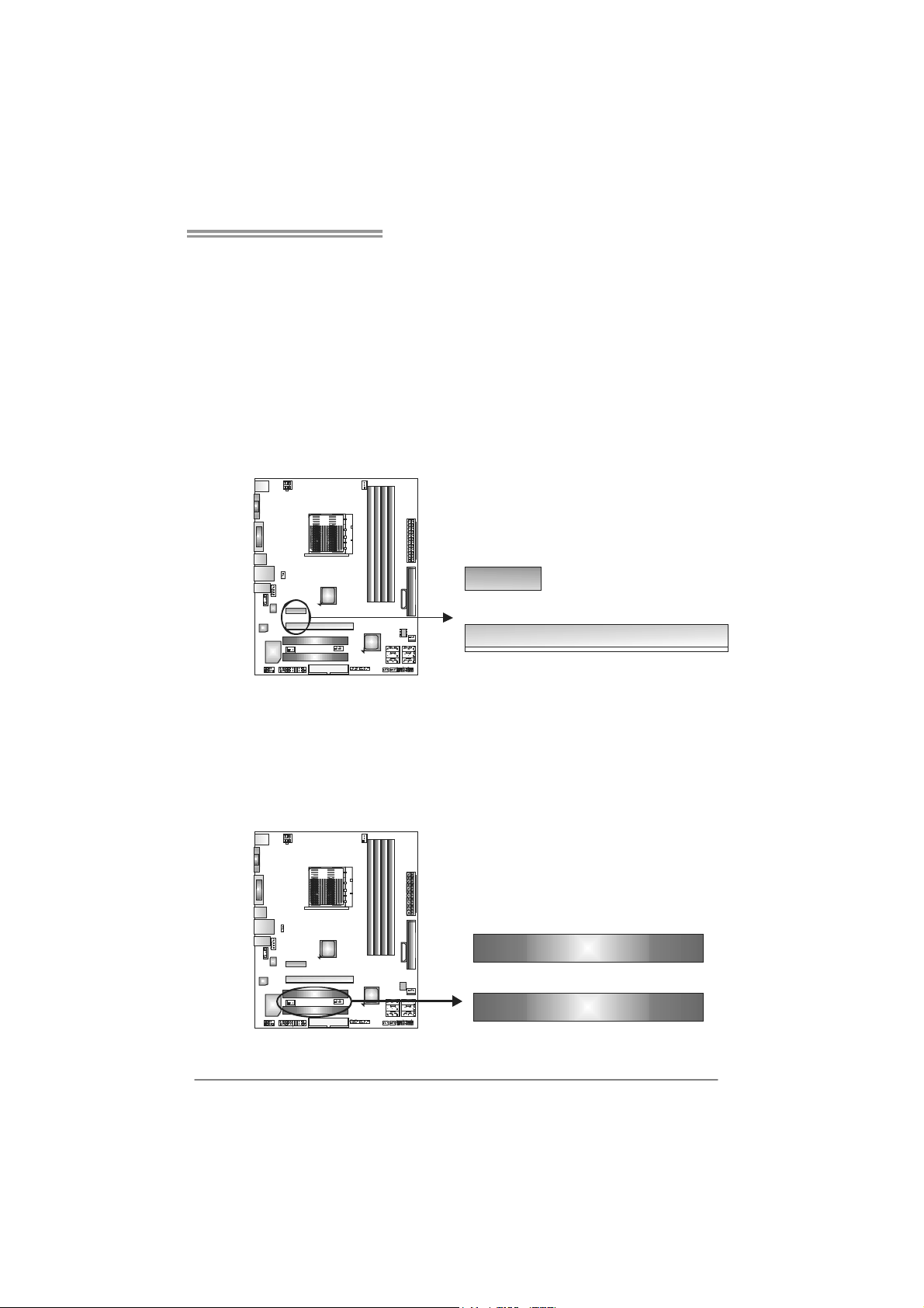
PEX16_1: PCI-Express Gen2 x16 Slot
- PCI-Express 2.0 compliant.
- Maximum theoretical realized bandwidth of 8GB/s simultaneously per
direction, for an aggregate of 16GB/s totally.
PEX1_1: PCI-Express Gen2 x1 Slot
- PCI-Express 2.0 compliant.
- Data transfer bandwidth up to 500MB/s per direction; 1GB/s in total.
- PCI-Express Gen2 supports a raw bit-rate of 5.0Gb/s on the data pins.
- 2X bandwidth over the PCI-Express 1.0 architecture.
PE X1_1
PEX16_1
PCI1~PCI2: Peripheral Component Interconnect Slots
This motherboard is equipped with 2 standard PCI slots. PCI stands for
Peripheral Component Interconnect, and it is a bus standard for expansion
cards. This PCI slot is designated as 32 bits.
PCI1
PCI2
11
Page 14
Motherboard Manual
CHAPTER 3: HEADERS & JUMPERS SETUP
3.1 H
OW TO SETUP JUMPERS
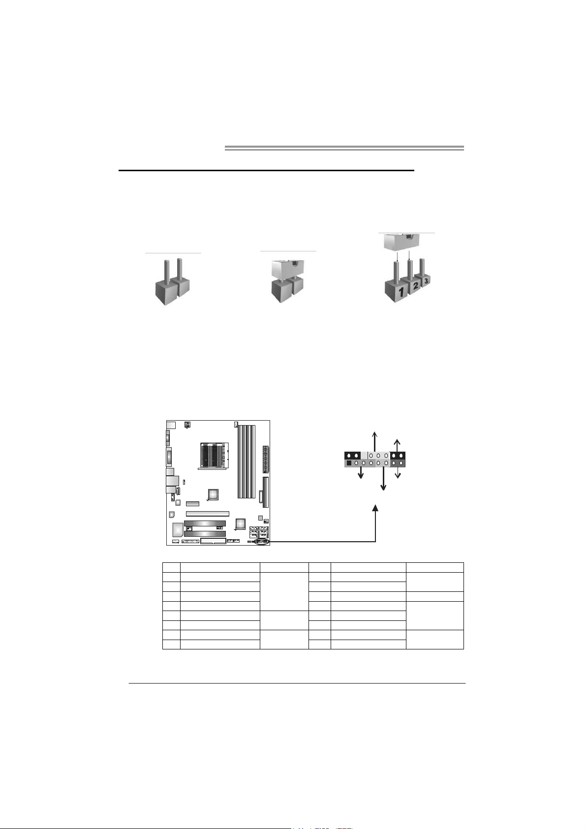
The illustration shows how to set up jumpers. When the jumper cap is
placed on pins, the jumper is “close”, if not, that means the jumper is
“open”.
Pin opened Pin closed Pin1-2 closed
3.2 DETAIL SETTINGS
JPANEL1: Front Panel Header
This 16-pin connector includes Power-on, Reset, HDD LED, Power LED, and
speaker connection. It allows user to connect the PC case’s front panel switch
functions.
PWR_LED
On/Off
-
9
1
++
SPK
HLED
16
8
-
+
RS T
12
Pin Assignment Function Pin Assignment Function
1 +5V 9 N/A
2 N/A 10 N/A
3 N/ A 11 N/A N/A
4 Speaker
5 HDD LED (+) 13 Power LED (+)
6 HDD LED (-)
7 Ground 15 Power button
8 Reset control
Speaker
Connector
Hard drive
LED
Reset button
12 Power LED (+)
14 Power LED (-)
16 Ground
N/A
Power LED
Power-on button
Page 15
TA780G M2+/TA780G M2+ HP/TA760G M2+
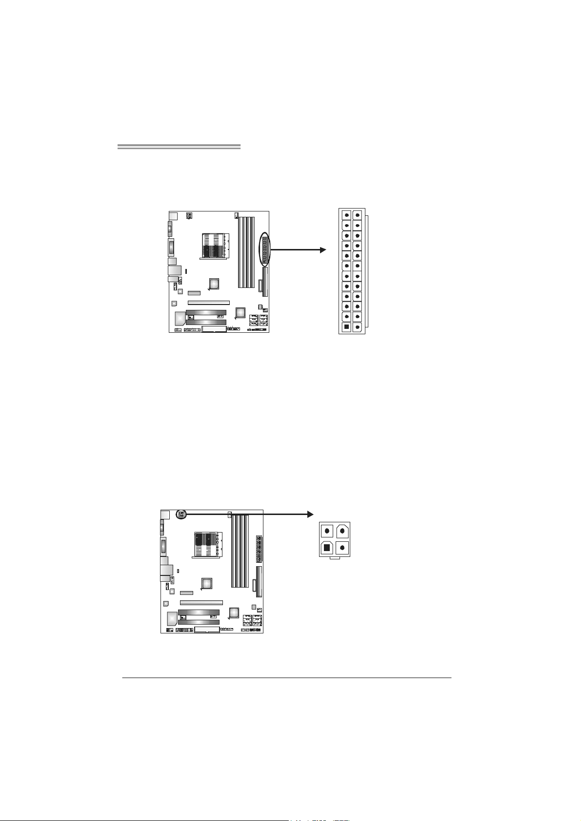
JATXPWR1: ATX Power Source Connector
This connector allows user to connect 24-pin power connector on the ATX
power supply.
12
1
Pin Assignment Pin Assignm ent
13 +3.3V 1 +3.3V
14 -12V 2 +3.3V
15 Ground 3 Ground
16 PS_ON 4 +5V
17 Ground 5 Ground
18 Ground 6 +5V
19 Ground 7 Ground
20 NC 8 PW_OK
21 +5V 9 Standby Voltage+5V
22 +5V 10 +12V
23 +5V 11 +12V
24 Ground 12 +3.3V
24
13
JATXPWR2: ATX Power Source Connector
By connecting this connector, it will provide +12V to CPU power circuit.
34
12
Pin
Assignment
1 +12V
2 +12V
3 Ground
4 Ground
13
Page 16
Motherboard Manual
JUSB2/JUSB3/JUSB4: Headers for USB 2.0 Ports at Front Panel
This header allows user to connect additional USB cable on the PC front panel,
and also can be connected with internal USB devices, like USB card reader.
JUSB4
JUSB3 JUSB2
210
19
SATA1~SATA6: Serial ATA Connectors
The motherboard has a PCI to SATA Controller with 6 channels SATA interface,
it satisfies the SATA 2.0 spec and with transfer rate of 3.0Gb/s.
SATA5 SATA6
SATA3 SATA4
SATA1 SATA2
Assignment
Pin
1 +5V (fused)
2 +5V (fused)
3 USB4 USB5 USB+
6 USB+
7 Ground
8 Ground
9 NC
10 Key
Assignment
Pin
1 Ground
2 TX+
3 TX4 Ground
5 RX6 RX+
7 Ground
14
7
14
Page 17
TA780G M2+/TA780G M2+ HP/TA760G M2+
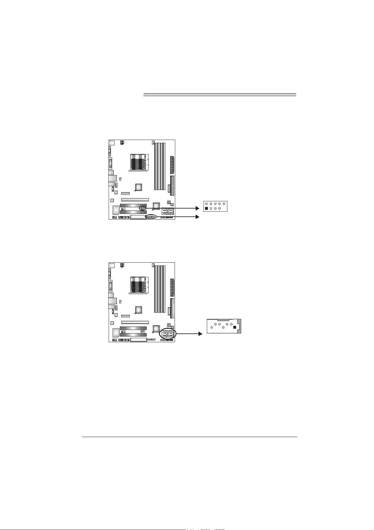
JSPDIF_OUT1: Digital Audio-out Connector
This connector allows user to connect the PCI bracket SPDIF output header.
Pin
Assignment
1 +5V
2 SPDIF_OUT
3 Ground
13
JAUDIOF1: Front Panel Audio Header
This header allows user to connect the front audio output cable with the PC front
panel. This header allows only HD audio front panel connector; AC’97 connector
is not acceptable.
Pin Assignment
1 Mic Left in
2 Ground
3 Mic Right in
4 GPIO
10
9
1
2
5 Right line in
6 Jack Sense
7 Front Sense
8 Key
9 Left line in
10 Jack Sense
15
Page 18
Motherboard Manual
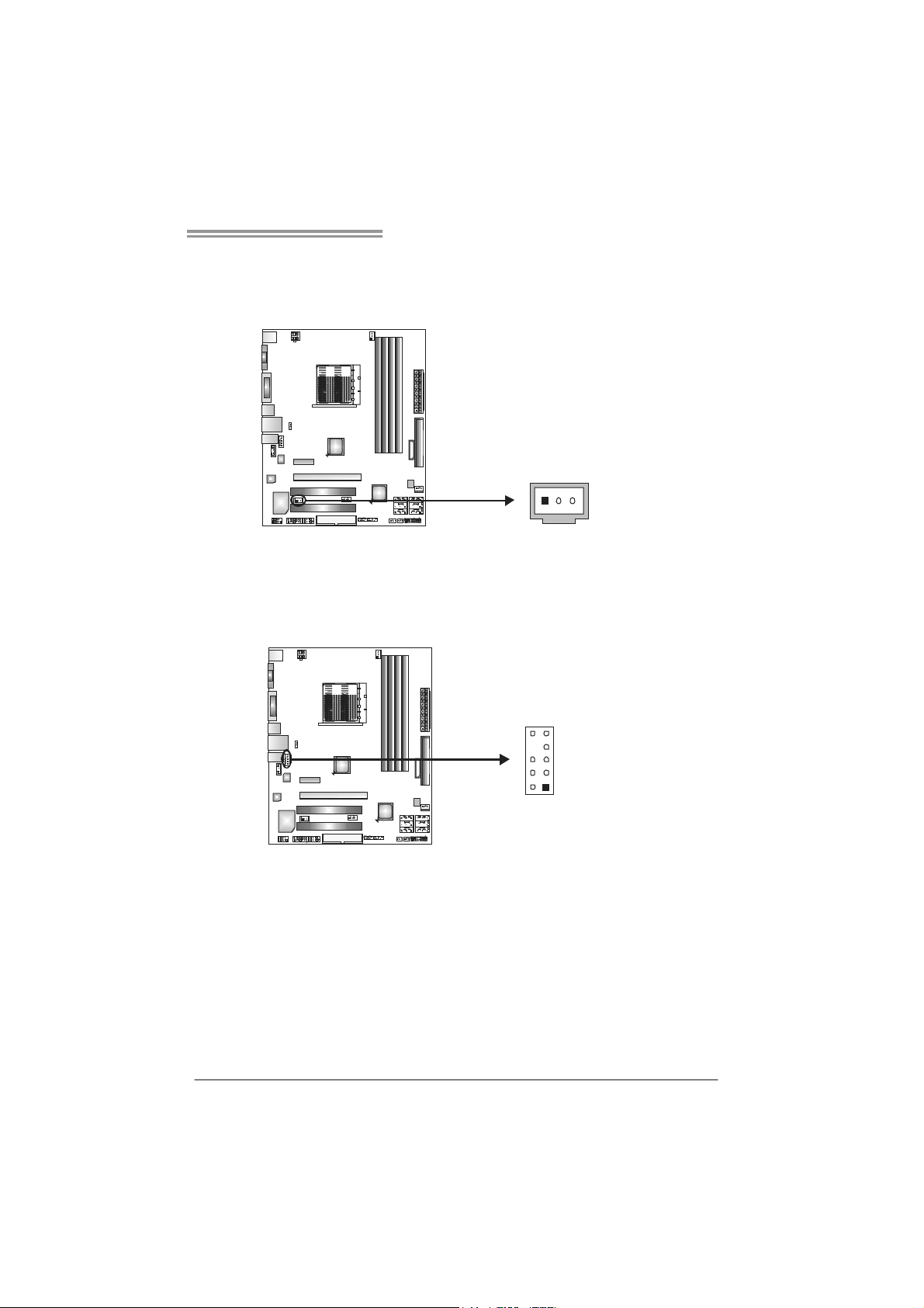
JCDIN1: CD-ROM Audio-in Connector
This connector allows user to connect the audio source from the variaty devices,
like CD-ROM, DVD-ROM, PCI sound card, PCI TV turner card etc.
JCMOS1: Clear CMOS Header
By placing the jumper on pin2-3, it allows user to restore the BIOS safe setting
and the CMOS data, please carefully follow the procedures to avoid damaging
the motherboard.
13
Pin
1 Left Channel
1
2 Ground
3 Ground
4 Right Channel
4
13
Pin 1-2 Close:
Normal Operation
(default).
13
Pin 2-3 Close:
Clear CMOS data.
Assignment
Input
Input
16
※ Clear CMOS Procedures:
1. Remove AC power line.
2. Set the jumper to “Pin 2-3 close”.
3. Wait for five seconds.
4. Set the jumper to “Pin 1-2 close”.
5. Power on the AC.
6. Reset your desired password or clear the CMOS data.
Page 19

TA780G M2+/TA780G M2+ HP/TA760G M2+
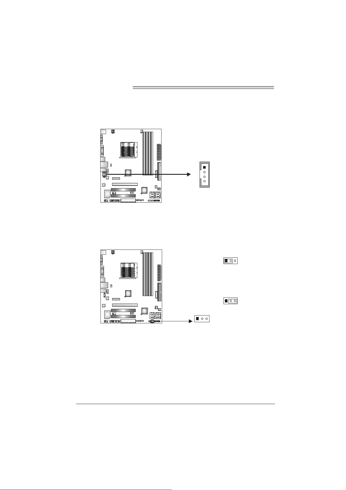
JPRNT1: Printer Port Connector
This header allows you to connector printer on the PC.
2
125
Pin Assignment Pin Assignment
1 -Strobe 14 Ground
2 -ALF 15 Data 6
3 Data 0 16 Ground
4 -Error 17 Data 7
5 Data 1 18 Ground
6 -Init 19 -ACK
7 Data 2 20 Ground
8 -Scltin 21 Busy
9 Data 3 22 Ground
10 Ground 23 PE
11 Data 4 24 Ground
12 Ground 25 SCLT
13 Data 5 26 Key
JCOM1: Serial port Connector
The motherboard has a Serial Port Connector for connecting RS-232 Port.
Pin
Assignment
1 Carrier detect
2 Received data
3 Transmitted data
4 Data terminal ready
5 Signal ground
6 Data set ready
7 Request to send
210
19
8 Clear to send
9 Ring indicator
10 NC
17
Page 20

Motherboard Manual
JUSBV1/JUSBV2: Power Source Headers for USB Ports
Pin 1-2 Close:
JUSBV1: +5V for USB ports at JUSB1/JUSBLAN1.
JUSBV2: +5V for USB ports at front panel (JUSB2/JUSB3/JUSB4).
Pin 2-3 Close:
JUSBV1: +5V STB for USB ports at JUSB1/JUSBLAN1.
JUSBV2: +5V STB for USB ports at front panel (JUSB2/JUSB3/JUSB4).
JUSBV1
1
3
13
JUSBV2
1
3
1
3
13
Pin 1-2 close
13
Pin 2-3 close
18
Page 21

TA780G M2+/TA780G M2+ HP/TA760G M2+
CHAPTER 4: RAID FUNCTIONS
4.1 O
z Supports Windows XP Home/Professional Edition, and Windows Vista.
PERATING SYSTEM
4.2 RAID ARRAYS
RAID supports the following types of RAID arrays:
RAID 0: RAID 0 defines a disk striping scheme that improves disk read and write times for
many applications.
RAID 1: RAID 1 defines techniques for mirroring data.
RAID 1+0: RAID 1+0 combines the techniques used in R AID 0 and RAID 1.
4.3 HOW RAID WORKS
RAID 0:
The controller “stripes” data across multip le drives in a RAID 0 array system. It breaks
up a large file into smaller b locks and performs disk reads and writes across multiple
drives in parallel. The size of each block is determined by the stripe size parameter,
which you set during the creation of the RAID set based on the system environment.
This technique reduces overall disk access time and offers high bandwidth.
Features and Benefits
- Drives: Minimum 1, and maximum is up to 6 or 8. Depending on the
platform.
- Uses: Intended for non-critical data requiring high data throughput, or any
environment that does not require fault tolerance.
- Benefits: provides increased data throughput, especially for large files.
No capacity loss penalty for parity.
- Drawbacks: Does not deliver any fault tolerance. If any drive in the array
fails, all data is lost.
- Fault Tolerance: No.
Block 1
Block 3
Block 5
Block 2
Block 4
Block 6
19
Page 22

Motherboard Manual
RAID 1:
Every read and write is actually carr ied out in parallel across 2 disk drives in a RAID 1
array system. The mirrored (backup) copy of the data can reside on the same disk or on
a second redundant drive in the array. RAID 1 provides a hot-standby copy of data if
the active volume or drive is corrupted or becomes unavailable because of a hardware
failure.
RAID techniques can be applied for high-ava ilability solutions, or as a form of
automatic backup that eliminates tedious manual backups to more expensive and less
reliable media.
Features and Benefits
- Drives: Minimum 2, and maximum is 2.
- Uses: RAID 1 is ideal for small databases or any other application that
requires fault tolerance and minimal capacity.
- Benefits: Provides 100% data redundancy. Should one drive fail, the
controller switches to the other drive.
- Drawbacks: Requires 2 drives for the storage space of one drive.
Performance is impaired during drive rebuilds.
- Fault Tolerance: Yes.
20
Block 1
Block 2
Block 3
Block 1
Block 2
Block 3
Page 23

TA780G M2+/TA780G M2+ HP/TA760G M2+
RAID 1+0:
RAID 1 drives can be stripped usin g RAID 0 techniques. Resulting in a RAID 1+0
solution for improved resiliency, performance and rebuild performance.
Features and Benefits
- Drives: Minimum 4, and maximum is 6 or 8, depending on the platform.
- Benefits: Optimizes for both fault tolerance and performance, allowing for
automatic redundancy. May be simultaneously used with other RAID
levels in an array, and allows for spare disks.
- Drawbacks: Requires twice the available disk space for data redundancy,
the same as RAID level 1.
- Fault Tolerance: Yes.
Block 1
Block 3
Block 5
Block 1
Block 3
Block 5
Block 2
Block 4
Block 6
Block 2
Block 4
Block 6
21
Page 24

Motherboard Manual
CHAPTER 5: T-SERIES BIOS & SOFTWARE
5.1 T-S
ERIES BIOS
T-Series BIOS Features
Overclocking Navigator Engine (O.N.E.)
Memory Integration Test (M.I.T., under Overclock Navigator Engine)
BIO-Flasher: Update BIOS file from USB Flash Drive or FDD
Self Recovery System (S.R.S)
Smart Fan Function
!! WARNING !!
For better system performance, the BIOS firmware is being
continuously updated. The BIOS information described below in
this manual is for your reference only and the actual BIOS
information and settings on board may be different from this
manual. For further information of setting up the BIOS, please
refer to the BIOS Manual in the Setup CD.
A. Overclocking Navigator Engine (O.N.E.)
ONE provides two powerful overclocking engines: MOS and AOS for both
Elite and Casual overclockers.
Main Advanced
T-Series Settings
WARNING: Setting wrong values in below sections
may cause system to malfunction.
OverClock Navigator [Normal]
=========== Automate OverClock System ===========
Auto OverClock System [V6-Tech Engine]
============ Manual OverClock System ============
CPU Overvoltage [StartUp]
Memory Overvoltage [1.95V]
Chipset Overvoltage [1.15V]
HT Overvoltage [1.20V]
CPU Frequency [200]
> CPU FID/VID Control
> DRAM Timing Configuration
> Hyper Transport Configuration
> Memory Configuration
Integrated Memory Test [Disabled]
vxx.xx (C)Copyright 1985-200x, American Megatrends, Inc.
PCIPnP Boot
BIOS SETUP UTILITY
Chipset T-Series
Exit
Options
Normal
Automate OverClock
Manual OverClock
Select Screen
Select Item
Change Option
+-
General Help
F1
Save and Exit
F10
Exit
ESC
22
Page 25

TA780G M2+/TA780G M2+ HP/TA760G M2+
Manual Overclock System (M.O.S.)
MOS is designed for experienced overclock users.
It allows users to customize personal overclock settings.
Main Advanced
T-Series Settings
WARNING: Setting wrong values in below sections
may caus e sys tem to malfunc tion .
OverClock Navigator [Normal]
=========== Automate OverClock System ===========
Aut o Ov erCl ock Sy st em [V6-T ec h Engi ne]
============ Manual OverClock System ============
CPU Overvoltage [StartUp]
Mem or y Over volt ag e [1. 95 V]
Chipset Overvoltage [1.15V]
HT Ov er volt age [ 1. 20V]
CPU Frequency [200]
> CPU FID/VID Control
> D RA M Ti ming C onfi guratio n
> Hyper Transport Configuration
> M em ory Conf ig urat ion
Integrated Memory Test [Disabled]
Main Advanced
T-Series Settings
WARNING: Setting wrong values in below sections
may caus e sys tem to malfunc tion .
OverClock Navigator [Manual OverClock]
=========== Automate OverClock System ===========
Aut o Ov erCl ock Sy st em [V6-T ec h Engi ne]
============ Manual OverClock System ============
CPU Overvoltage [StartUp]
Mem or y Over volt ag e [1. 95 V]
Chipset Overvoltage [1.15V]
HT Ov er volt age [ 1. 20V]
CPU Frequency [200]
> CPU FID/VID Control
> D RA M Ti ming C onfi guratio n
> Hyper Transport Configuration
> M em ory Conf ig urat ion
Integrated Memory Test [Disabled]
vxx. xx (C)Cop yrig ht 1985- 200x, Am eric an Me gatr ends, In c.
vxx. xx (C)Cop yrig ht 1985- 200x, Am eric an Me gatr ends, In c.
PCIP nP Boot
PCIP nP Boot
CPU Overvoltage
This function will increase CPU stability when overclocking. However, the
CPU temperature will increase when CPU voltage is increased.
Memory Overvoltage
This function will increase memory stability when overclocking.
Chipset Overvoltage
This function will increase Northbridge and Southbridge chipset stability
when overclocking.
HT Overvoltage
This function will increase CPU stability when overclocking the HT ratio.
BIOS SETUP UTILITY
Chip se t T-Series
Options
Norm al
Auto ma te O verC lo ck
Manual OverClock
↓
BIOS SETUP UTILITY
Chip se t T-Series
Opti on s
Normal
Automate OverClock
Man ua l Over Cloc k
+F1
F10
ESC
Opti on s
Normal
Automate OverClock
Man ua l Over Cloc k
+F1
F10
ESC
Exit
Select Screen
Select Item
Change Option
General Help
Sav e an d Exit
Exit
Exit
Select Screen
Select Item
Change Option
General Help
Sav e an d Exit
Exit
23
Page 26

Motherboard Manual
p
CPU Frequency
CPU Frequency is directly in proportion to system performance. To
maintain the system stability, CPU voltage needs to be increased also
when raising CPU frequency.
CPU FID/VID Control
Enter this function for more advanced CPU settings.
DRAM Timing Co nfiguratio n
Enter this function for more advanced DRAM clock settings.
Hyper Transpo rt Co nf ig uration
Enter this function for more advanced Hyper Transport settings.
Memory Co nfig uratio n
Enter this function for more advanced memory settings.
NOTE
Overclock is an optional process, but not a “must-do” process; it is
not recommended for inexperienced users. Therefore, we will not
be responsible for any hardware damage which may be caused by
overclocking. We also would not guarantee any overclocking
erformance.
24
Automatic Overclock System (A.O.S.)
For beginners in overclock field, BET had developed an easy, fast, and
powerful feature to increase the system performance, named A.O.S.
Based on many tests and experiments, A.O.S. provides 3 ideal overclock
configurations that are able to raise the system performance in a single
step.
Main Advanced
T-Series Settings
WARNING: Setting wrong values in below sections
may caus e sys tem to malfunc tion .
OverClock Navigator [Normal]
=========== Automate OverClock System ===========
Aut o Ov erCl ock Sy st em [V6-T ec h Engi ne]
============ Manual OverClock System ============
CPU Overvoltage [StartUp]
Mem or y Over volt ag e [1.95 V]
Chipset Overvoltage [1.15V]
HT Ov er volt age [ 1. 20V]
CPU Frequency [200]
> CPU FID/VID Control
> D RA M Ti ming C onfi gur atio n
> Hyper Transport Configuration
> M em ory Conf ig urat ion
Integrated Memory Test [Disabled]
vxx. xx (C)Cop yrig ht 1985- 20 0x, Am eric an Me gatr en ds, In c.
PCIP nP Boot
BIOS SETUP UTILITY
Chip se t T-Series
Options
Norm al
Auto ma te O verC lo ck
Manual OverClock
Opti on s
Normal
Automate OverClock
Man ua l Over Cloc k
+F1
F10
ESC
Exit
Select Screen
Select Item
Change Option
General Help
Sav e an d Exit
Exit
Page 27

TA780G M2+/TA780G M2+ HP/TA760G M2+
V6 Tech Engine
This engine will make a good over-clock performance.
Main Advanced
T-Series Settings
WARNING: Setting wrong values in below sections
may caus e sys tem to malfunc tion .
OverClock Navigator [Automate OverClock]
=========== Automate OverClock System ===========
Aut o Ov erCl ock Sy st em [V6-T ec h Engi ne]
============ Manual OverClock System ============
CPU Overvoltage [StartUp]
Mem or y Over volt ag e [1.95 V]
Chipset Overvoltage [1.15V]
HT Ov er volt age [ 1. 20V]
CPU Frequency [200]
> CPU FID/VID Control
> D RA M Ti ming C onfi gur atio n
> Hyper Transport Configuration
> M em ory Conf ig urat ion
Integrated Memory Test [Disabled]
vxx. xx (C)Cop yrig ht 1985- 20 0x, Am eric an Me gatr en ds, In c.
PCIP nP Boot
BIOS SETUP UTILITY
Chip se t T-Series
V8 Tech Engine
This engine will make a better over-clock performance.
Main Advanced
T-Series Settings
WARNING: Setting wrong values in below sections
may caus e sys tem to malfunc tion .
OverClock Navigator [Automate OverClock]
=========== Automate OverClock System ===========
Aut o Ov erCl ock Sy st em [V8-T ec h Engi ne]
============ Manual OverClock System ============
CPU Overvoltage [StartUp]
Mem or y Over volt ag e [1.95 V]
Chipset Overvoltage [1.15V]
HT Ov er volt age [ 1. 20V]
CPU Frequency [200]
> CPU FID/VID Control
> D RA M Ti ming C onfi gur atio n
> Hyper Transport Configuration
> M em ory Conf ig urat ion
Integrated Memory Test [Disabled]
vxx. xx (C)Cop yrig ht 1985- 20 0x, Am eric an Me gatr en ds, In c.
PCIP nP Boot
BIOS SETUP UTILITY
Chip se t T-Series
V12 Tech Engine
This engine will make a best over-clock performance.
Main Advanced
T-Series Settings
WARNING: Setting wrong values in below sections
may caus e sys tem to malfunc tion .
OverClock Navigator [Automate OverClock]
=========== Automate OverClock System ===========
Auto OverClock System [V12-Tech Engine]
============ Manual OverClock System ============
CPU Overvoltage [StartUp]
Mem or y Over volt ag e [1.95 V]
Chipset Overvoltage [1.15V]
HT Ov er volt age [ 1. 20V]
CPU Frequency [200]
> CPU FID/VID Control
> D RA M Ti ming C onfi gur atio n
> Hyper Transport Configuration
> M em ory Conf ig urat ion
Integrated Memory Test [Disabled]
vxx. xx (C)Cop yrig ht 1985- 20 0x, Am eric an Me gatr en ds, In c.
PCIP nP Boot
BIOS SETUP UTILITY
Chip se t T-Series
Exit
Opti on s
Normal
Automate OverClock
Man ua l Over Cloc k
Select Screen
Select Item
Change Option
+-
General Help
F1
Sav e an d Exit
F10
Exit
ESC
Exit
Opti on s
Normal
Automate OverClock
Man ua l Over Cloc k
Select Screen
Select Item
Change Option
+-
General Help
F1
Sav e an d Exit
F10
Exit
ESC
Exit
Opti on s
Normal
Automate OverClock
Man ua l Over Cloc k
Select Screen
Select Item
Change Option
+-
General Help
F1
Sav e an d Exit
F10
Exit
ESC
25
Page 28

Motherboard Manual
Notices:
1. Not all types of AMD CPU perform above overclock setting ideally; the difference will be based
on the selected CPU model.
B. Memory Integration Test (M.I.T.)
This function is under “Overclocking Navigator Engine” item.
MIT allows users to test memory compatibilities, and no extra devices or
software are needed.
Step 1
The default setting under this item is “Disabled”; the condition parameter should
be changed to “Enable” to proceed this test.
PCIP nP Boot
PCIP nP Boot
26
Main Advanced
T-Series Settings
WARNING: Setting wrong values in below sections
may caus e sys tem to malfunc tion .
OverClock Navigator [Normal]
=========== Automate OverClock System ===========
Aut o Ov erCl ock Sy st em [V6-T ec h Engi ne]
============ Manual OverClock System ============
CPU Overvoltage [StartUp]
Mem or y Over volt ag e [1.95 V]
Chipset Overvoltage [1.15V]
HT Ov er volt age [ 1. 20V]
CPU Frequency [200]
> CPU FID/VID Control
> D RA M Ti ming C onfi gur atio n
> Hyper Transport Configuration
> M em ory Conf ig urat ion
Integrated Memory Test [Disabled]
Main Advanced
T-Series Settings
WARNING: Setting wrong values in below sections
may caus e sys tem to malfunc tion .
OverClock Navigator [Normal]
=========== Automate OverClock System ===========
Aut o Ov erCl ock Sy st em [V6-T ec h Engi ne]
============ Manual OverClock System ============
CPU Overvoltage [StartUp]
Mem or y Over volt ag e [1.95 V]
Chipset Overvoltage [1.15V]
HT Ov er volt age [ 1. 20V]
CPU Frequency [200]
> CPU FID/VID Control
> D RA M Ti ming C onfi gur atio n
> Hyper Transport Configuration
> M em ory Conf ig urat ion
Integrated Memory Test [Enabled]
vxx. xx (C)Cop yrig ht 1985- 20 0x, Am eric an Me gatr en ds, In c.
vxx. xx (C)Cop yrig ht 1985- 20 0x, Am eric an Me gatr en ds, In c.
Step 2
Save and Exit from CMOS setup and reboot the system to activate this test.
Run this test for 5 minutes (minimum) to ensure the memory stability.
Step 3
When the process is done, change the setting back from “Enable” to “Disable”
to complete the test.
BIOS SETUP UTILITY
Chip se t T-Series
↓
BIOS SETUP UTILITY
Chip se t T-Series
Exit
Opti on s
Normal
Automate OverClock
Man ua l Over Cloc k
Select Screen
Select Item
Change Option
+-
General Help
F1
Sav e an d Exit
F10
Exit
ESC
Exit
Opti on s
Normal
Automate OverClock
Man ua l Over Cloc k
Select Screen
Select Item
Change Option
+-
General Help
F1
Sav e an d Exit
F10
Exit
ESC
Page 29

C. BIO-Flasher
BIO-Flasher is a BIOS flashing utility providing you an easy and simple way to
update your BIOS via USB pen drive or floppy disk.
The BIO-Flasher is built in the BIOS chip. To enter the utility, press <F12>
during the Power-On Self Tests (POST) procedure while booting up.
Updating BIOS with BIO-Flasher
1. Go to the website to download the latest BIOS file for the motherboard.
2. Then, save the BIOS file into a USB pen drive or a floppy disk.
3. Insert the USB pen drive or the floppy disk that contains the BIOS file to the
USB port or the floppy disk drive.
4. Power on or reset the computer and then
press <F12> during the POST process.
A select dialog as the picture on the right
appears.
Select the device contains the BIOS file and
press <Enter> to enter the utility.
TA780G M2+/TA780G M2+ HP/TA760G M2+
5. The utility will show the BIOS
files and their respective
information. Select the proper
BIOS file and press <Enter>
then <Y> to perform the BIOS
update process.
6. After the update process, the utility will ask you to reboot the system.
Press <Y> to proceed. BIOS update completes.
z This utility only allows storage device with FAT32/16 format and single
parti tion.
z Shutting down or resetting the system while updating the B IOS will lead to
system boot failure.
27
Page 30

Motherboard Manual
D. Self Recovery System (S.R.S.)
This function can’t be seen under BIOS setup; and is always on whenever the
system starts up.
However, it can prevent system hang-up due to inappropriate overclock
actions.
When the system hangs up, S.R.S. will automatically log in the default BIOS
setting, and all overclock settings will be re-configured.
E. Smart Fan Function
Smart Fan Function is under “Smart Fan Configuration” in “Advanced Menu”.
This is a brilliant feature to control CPU/System Temperature vs. Fan speed.
When enabling Smart Fan function, Fan speed is controlled automatically by
CPU/System temperature.
This function will protect CPU/System from overheat problem and maintain the
system temperature at a safe level.
Main Advanced
WARNING: Setting wrong values in below sections
may cause system to malfunction.
> CPU Configuration
> SuperIO Configuration
> Smart Fan Configuration
> Hardware Health Configuration
> ACPI Configuration
> USB Configuration
MPS Revision [1.4]
PCIPnP Boot
BIOS SETUP UTILITY
Chipset T-Series
Configure CPU.Advanced Settings
Select Screen
Select Item
Go to Sub Screen
Enter
General Help
F1
Save and Exit
F10
Exit
ESC
Exit
28
vxx.xx (C)Copyright 1985-200x, American Megatrends, Inc.
↓
Advanced
Smart Fan Configuration
CPU Smart Fan [Disabled]
Smart Fan Calibration
Control Mode
Fan Ctrl OFF( C)
Fan Ctrl On( C)
Fan Ctrl Start value
Fan Ctrl Sensitive
o
o
vxx.xx (C)Copyright 1985-200x, American Megatrends, Inc.
BIOS SETUP UTILITY
When you choice [Auto]
,[3Pin] or [4Pin],
please run the
calibration to define
the Fan parameters for
Smart Fan control
Select Screen
Select Item
Change Option
+-
General Help
F1
Save and Exit
F10
Exit
ESC
Page 31

TA780G M2+/TA780G M2+ HP/TA760G M2+
Smart Fan Calibration
Choose this item and then the BIOS will automatically test and detect the
CPU/System fan functions and show CPU/System fan speed.
Control Mode
This item provides several operation modes of the fan.
Fan Ctrl OFF(℃)
If the CPU/System temperature is lower than the set value, the CPU/
System fan will turn off. The range is from 0~127, with an interval of 1.
Fan Ctrl On(℃)
The CPU/System fan starts to work when CPU/System temperature
arrives to this set value. The range is from 0~127, with an interval of 1.
Fan Ctrl Start Value
When CPU/System temperature arrives to the set value, the CPU/System
fan will work under Smart Fan Function mode. The range is from 0~127,
with an interval of 1.
Fan Ctrl Sensitive
Increasing the value of slope PWM will raise the speed of CPU/System fan.
The range is from 1~127, with an interval of 1.
29
Page 32

Motherboard Manual
5.2 T-SERIES SOFTWARE
Installing T-Series Software
1. Insert the Setup CD to the optical drive. The drivers installation program
would appear if the Autorun function has been enabled.
2. Select Software In stallation, and then click on the respective software
title.
3. Follow the on-screen instructions to complete the installation.
Launching T-Series Software
After the installation process, you will see the software icon “HW Monitor”/
“eHOT Line” / “Tseries BIOS Update” appears on the desktop. Double-click
the icon to launch T-Series utility.
Hardware Monitor
HW Monitor is a monitor utility that helps you to maintain the health of the PC.
It provides real-time information of CPU/GPU/System temperat ure, fan speed,
and voltage.
Thi s area sh ows vol t age in forma tion
Vol tag e Pa ne l Fan Pa nel
Thi s area sh ows CPU in f orma tion
Thi s area s hows CPU/ Syst em t emper atur e
30
Tu rn t o Fa n Pa nel
Thi s area sh ows CPU/ Syst em f an spe ed
Turn to Voltage Panel
Page 33

TA780G M2+/TA780G M2+ HP/TA760G M2+
e
eHot-Line (Optional)
eHot-Line is a convenient utility that helps you to contact with our
Tech-Support system. This utility will collect the system information which is
useful for analyzing the problem you may have encountered, and then send
these information to our tech-support department to help you fix the problem.
Before you use this uti lity, please set O utlook Express as yo ur default e-mail client application program.
rep resents import ant
*
information that you
must provi de. Withou t
this informat ion, you may
not be able to send ou t
the mail.
This block will show
the infor mation which
would be collect ed in
the mail.
Send the mail ou t.
Describe co ndition
*
of your syst em.
Save these information to a .txt fil
Exit this dialog.
Select your area or
*
the area clos e to yo u.
Provid e the e-mail
addres s that you woul d
like to send the copy to.
Provide t he name of
*
the memory module
manufactu rer.
Provid e the name of
the power supply
manufac turer and the
model no .
After filling up this information, click “Send”
to send the mail out. A warning dialog would
appear asking for your confirmation; click
“Send” to confirm or “Do Not Send” to cancel.
If you want to save this information to a .txt file, click “Save As…” and then you
will see a saving dialog appears asking you to enter file name.
31
Page 34

Motherboard Manual
Enter the file name and then click
“Save”. Your system information
will be saved to a .txt file.
We will not share customer’s data with any other third parties,
so please feel free to provide your system information while using
eHot-Line service.
Open the saved .txt file, you will see
your system information including
motherboard/BIOS/CPU/video/
device/OS information. This
information is also concluded in the
sent mail.
32
If you are not using Outlook Express as your default e-mail client
application, you may need to save the system information to a .txt file
and send the file to our tech support with other e-mail application.
Go to the following web
http://www.biostar.com.tw/app/en-us/about/contact.php for getting
our contact information.
Page 35

TA780G M2+/TA780G M2+ HP/TA760G M2+
BIOS Update
BIOS Update is a convenient utility which allows you to update your
motherboard BIOS under Windows system.
AWARD BIOS AMI BIOS
Clear CMOS function
(Only for AWARD BIOS)
Show current BIOS information
Save cur rent B IOS
to a .bin file
Update BIOS
with a BIOS file
<Backup BIOS>
Once click on this button, the saving
dialog will show. Choose t he
position to save file and enter file
name. (We recommend that the file
name should be English/number
and no longer than 7 characters.)
Then click Save.
After the saving process, finish
dialog will show. Click on OK to
complete the BIOS Backup
procedure.
33
Page 36

Motherboard Manual
<Update BIOS>
Before doing this, please download the proper BIOS file from the website.
For AWARD BIOS, update BIOS procedure
should be run with Clear CMOS function, so
please check on Clear CMOS first.
Then click Update BIOS button, a
dialog will show for asking you backup
current BIOS. Click Yes for BIOS
backup and refer to the Backup BIOS
procedure; or click No to skip this
procedure.
After the BIOS Backup procedure, the
open dialog will show for requesting the
BIOS file which is going to be updated.
Please choose the proper BIOS file for
updating, then click on Open.
The utility will update BIOS with the
proper BIOS file, and this process may
take minutes. Please do not open any
other applications during this process.
After the BIOS Update process, click on
OK to restart the system.
While the system boots up and the full screen logo shows, press <Delete>
key to enter BIOS setup.
In the BIOS setup, use the Load Optimized Defaults function and then Save and
Exit Setup to exit BIOS setup. BIOS Update is completed.
All the information and content above about the T-Series software are subject to be
changed without notice. For better performance, the software is being continuously
updated. The information and pictures described above are for your reference only.
The actual i nformation and settings on board may be slightly different from this
manual.
34
Page 37

TA780G M2+/TA780G M2+ HP/TA760G M2+
CHAPTER 6: USEFUL HELP
6.1 D
RIVER INSTALLATION NOTE
After you installed your operating system, please insert the Fully Setup
Driver CD into your optical drive and install the driver for better system
performance.
You will see the following window after you insert the CD
The setup guide will auto detect your motherboard and operating system.
Note:
If this window didn’t show up after you insert the Driver CD, please use file browser to
locate and execute the file SETUP.EXE under your optical drive.
A. Driver Installation
To install the driver, please click on the Driver icon. The setup guide will
list the compatible driver for your motherboard and operating system.
Click on each device driver to launch the installation program.
B. Software Installation
To install the software, please click on the Software icon. The setup guide
will list the software available for your system, click on each software title
to launch the installation program.
C. Manual
Aside from the paperback manual, we also provide manual in the Driver
CD. Click on the Manual icon to browse for available manual.
Note:
You will need Acrobat Reader to open the manual file. Please download the latest version
of Acrobat Reader so ftware from
http://www.adobe.com/products/acrobat/readstep2.html
35
Page 38

Motherboard Manual
6.2 EXTRA INFORMATION
CPU Overheated
If the system shutdown automatically after power on system for
seconds, that means the CPU protection function has been activated.
When the CPU is over heated, the motherboard will shutdown
automatically to avoid a damage of the CPU, and the system may not
power on again.
In this case, please double check:
1. The CPU cooler surface is placed evenly with the CPU surface.
2. CPU fan is rotated normally.
3. CPU fan speed is fulfilling with the CPU speed.
After confirmed, please follow steps below to relief the CPU protection
function.
1. Remove the power cord from power supply for seconds.
2. Wait for seconds.
3. Plug in the power cord and boot up the system.
Or you can:
1. Clear the CMOS data.
(See “Close CMOS Header: JCMOS1” section)
2. Wait for seconds.
3. Power on the system again.
36
Page 39

6.3 TROUBLESHOOTING
Probable Solution
1. No power to the system at all
Power light don’t illuminate, fan
inside power supply does not turn
on.
2. Indicator light on keyboard does
not turn on.
System inoperative. Keyboard lights
are on, power indicator lights are lit,
and hard drive is spinning.
System does not boot from hard disk
drive, can be booted from optical drive.
System only boots from optical drive.
Hard disk can be read and applications
can be used but booting from hard disk
is impossible.
Screen message says “Invalid
Configuration” or “CMOS Failure.”
Cannot boot system after installing
second hard drive.
TA780G M2+/TA780G M2+ HP/TA760G M2+
1. Make sure power cable is
securely plugged in.
2. Replace cable.
3. Contact technical support.
Using even pressure on both ends of
the DIMM, press down firmly until the
module snaps into place.
1. Check cable running from disk to
disk controller board. Make sure
both ends are securely plugged
in; check the drive type in the
standard CMOS setup.
2. Backing up the hard drive is
extremely important. All hard
disks are capable of breaking
down at any time.
1. Back up data and applications
files.
2. Reformat the hard drive.
Re-install applications and data
using backup disks.
Review system’s equipment. Make sure
correct information is in setup.
1. Set master/slave jumpers
correctly.
2. Run SETUP program and select
correct drive types. Call the drive
manufacturers for compatibility
with other drives.
37
Page 40

Motherboard Manual
APPENDENIX: SPEC IN OTHER LANGUAGES
G
ERMAN
Sp ezif ika tio nen
Sockel AM2+ / AM2
CPU
FSB
Chipsatz
Super E/A
Arbeitsspeich
er
Grafik
IDE
SATA
LAN
HD
Audio-Unters
tützung
Onboard-Ans
chluss
AMD Athlon 64 / Ath lon 64 FX / Althlon 64
X2 / S empron / Ph enom Pro zessoren
Athlon Max. Power: 125W
Pheno m Max. Power: 95W
Unterstützt HyperTransport 3.0 mit einer
Bandbreite von bis zu 5.2 GT/s
AMD 780G (TA760G M2+: AMD 760G)
AMD SB700 (TA760G M2+: AMD SB710)
ITE8718F
Biet et die h äuf ig verwendeten alten Super
E/A-Funktionen.
DDR2 DIMM-Steckplätze x 4
Max. 16GB Arbeitsspeicher
Jeder DIMM unterstützt
256MB/512MB/1GB/2GB/4GB DDR2.
Integrierter AMD 780G/760G-Chipsatz
Int eg riert er IDE - Con tro ller
Integrierter Serial ATA-Controller
Realtek RTL 8111C
ALC662
PCI Express Gen2 x16 Steckplatz x1
PCI Express Gen2 x1 Steckplatz x1 Steckplätze
PCI-Steckp latz x2
Diskettenlaufwerkanschluss x1 Jeder Anschluss unterstützt 2 Diskettenlaufwerke
IDE-Anschluss x1 Jeder Anschluss unterstützt 2 IDE-Laufwerke
SATA-Anschluss x6 Jeder Anschluss unterstützt 1 SATA-Laufwerk
Die AMD 64-Archit ektur unterstützt eine 32-Bit- und
64-Bit-Datenverarbeitung
Unterstützt Hyper Transport 3.0 und Cool’n’Quiet
Low Pin Count-Schnittstelle
Umgebungskontrolle,
Hardware-Überwachung
"Smart Guardian"-Funktion von ITE
Dual-Kanal DDR2 Speichermodul
Unterstützt DDR2 533 / 667 / 800
Unterstützt DDR2 1066 (for AM2+ CPU only)
registrierte DIMMs. ECC DIMMs werden nicht
unterstützt.
Max. 512MB gemeinsam benutzter Videospeicher
Unterstützt DX10
Unterstützt DVI
Ultra DMA 33 / 66 / 100 / 133 Bus Master-Modus
Unterstützt PIO-Modus 0~4,
Datentransferrate b is zu 3 Gb /s
Konform mit der SATA-Spezifikation Version 2.0.
10 / 100 /1000 Mb/s Auto-Negotiation
Halb-/ Vollduplex-Funktion
5.1-Kanal-Audioausgabe
Unterstützt High-Definition Audio
38
Page 41

Rückseiten-E
/A
Platinengröß
e
Sonderfunkti
onen
OS-Unterstü
tzung
TA780G M2+/TA780G M2+ HP/TA760G M2+
Sp ezif ika tio nen
Fronttafelanschluss x1 Unterstützt die Fronttafelfunktionen
Front-Audioanschluss x1 Unterstützt die Fronttafel-Audioanschlussfunktion
CD-IN-Anschluss x1 Unterstützt die CD Audio-In-Funktion
S/PDIF- Ausgangsanschluss x1 Unterstützt die digitale Audioausgabefunktion
CPU-Lüfter-Sockel x1
System-Lüfter-Sockel x1 System-Lüfter-Stromversorgungsanschluss
"CMOS lös chen"-Socke l x1
USB-Anschluss x3
Stromanschluss (24-polig) x1
St romans chlus s (4-po lig) x1
Druckeranschluss Anschluss x1 Jeder Anschluss unterstützt 1 Druckeranschluss
Serieller Anschluss x1
PS/2-Tastatur x1
PS/2-Maus x1
VGA-Anschluss x1
LAN-Anschluss x1
USB-Anschluss x4
Audioanschluss x3
DVI-Anschluss x1
215 mm (B) X 244 mm (L)
Unterstützt RAID 0 / 1 / 1+0
Windows XP / VISTA
CPU-Lüfterstromversorgungsanschluss (mit Smart
Fan -F un ktio n)
Jeder Anschluss unterstützt 2
Fronttafel-USB-Anschlüsse
Biostar behält s ich das Recht vor, ohne Ankünd igung
die Unterstützung für ein Betriebssystem
hinzuzufügen oder zu entfernen.
39
Page 42

Motherboard Manual
FRENCH
Socket AM2+ / AM2
Processeurs AMD Athlon 64 / Athlon 64 FX
UC
Bus frontal
Chipset
Super E/S
Mémoire
principale
Graphiques Integré dans la chipset AMD 780G/760G
IDE Contrôleur IDE intégré
SATA
LAN Realtek RTL 8111C
Prise en
charg e
aud io HD
Fentes
Connecteur
embarqu é
/ Alth lon 64 X2 / Sempron / Phenom
Athlon Max. Power: 125W
Pheno m Max. Power: 95W
Prend en charge Hyp er Transport 3.0
jusqu'à une bande passante de 5.2 GT/s
AMD 780G (TA760G M2+: AMD 760G)
AMD SB700 (TA760G M2+: AMD SB710)
ITE 8718F
Fournit la fonctionnalité de Super E/S
patrimoniales la plus utilisée.
Fentes DDR2 DIMM x 4
Capacité mémo ire max i male de 16 Go
Chaque DIMM prend en charge des DDR2
de 256 Mo/512 Mo et 1Go/2Go/4Go
Contrô leur Serial ATA int é gr é
ALC662
Fente PCI Express Gen2 x16 x1
Fente PCI Express Gen2 x1 x1
Fente PCI x2
Connecteur de disquette x1
Connecteur IDE x1
SPEC
L'architecture AMD 64 permet le calcul 32 et 64 bits
Prend en charge Hyper Trans port 3.0 et Cool’n’Qu iet
Int e rf a ce à f aib le co mpt e d e b roches
Initiatives de contrôle environnementales,
Mon iteur d e mat ériel
Fonction "Gardien intelligent" de l'ITE
Module d e mémo ire DDR2 à mode à do uble vo ie
Prend en charge la DDR2 533 / 667 / 800
Prend en charge la DDR2 1066 (for AM2+ CPU only)
Les DIMM à registres et DIMM avec code correcteurs
d'erreurs ne sont pas prises en charge
Mémoire vidéo partagée maximale de 512 Mo
Prise en charge DX10
Prise en charge DV I
Mode principale de Bus Ultra DMA 33 / 66 / 100 / 133
Prend en charge le mode PIO 0~4,
Taux de transfert jusqu'à 3 Go/s.
Co nfo rme à l a s péc if icat ion SATA Vers ion 2.0
10 / 100 /1000 Mb/s négociation auto matique
Half / Full duplex capability
Sortie aud io à 5 .1 voies
Prise en charge de l'audio haut e définition
Chaque co nne cto r prend en ch arg e 2 lecteurs de
disquettes
Chaque connecteur prend en charge 2 pér ip hér iqu es
IDE
40
Page 43

Connecteur SATA x6
Connecteur du panneau avant x1 Prend en charge les équipements du panneau avant
Connecteur Audio du panneau avant x1 Prend en charge la fonction audio du panneau avant
Connecteur d' entrée CD x 1 Prend en charge la fonction d'entrée aud io de CD
Connecteur de sortie S/PDIF x1 Prend en charge la fonction de sortie audio numérique
Embase de ventilateur UC x1
Embase de ventilateur système x1 Alimentation électrique du ventilateur système
Embase d'effacement CMOS x1
Connecteur USB x3
Connecteur d' aliment ation x 1
(24 broches)
Connecteur d' aliment ation x 1
(4 broch es)
Connecteur de Port d'imprimante x1
Connecteur de Port série x1
Clavier PS/2 x1
Souris PS/2 x1
E/S du
panneau
arrière
Dimension
s de la
cart e
Fonctionnal
ité s
spéciales
Support SE Windows XP / VISTA
Port VGA x1
Port LA N x1
Port USB x4
Fiche aud io x3
Port DV I x 1
215 mm (l) X 244 mm (H)
Prise en charge RAID 0 / 1 / 1 +0
TA780G M2+/TA780G M2+ HP/TA760G M2+
SPEC
Chaque connecteur prend en charge 1 pér ip hér iqu e
SATA
Alimentation électrique du ventilateur UC (avec
fonction de ventilateur intelligent)
Chaque connecteur prend en charge 2 ports USB de
panneau avant
Chaque co nne cto r prend en ch arg e 1 Port
d'imprimante
Biostar se réserve le droit d'ajouter ou de supprimer le
support de SE avec ou sans préavis.
41
Page 44

Motherboard Manual
ITALIAN
Socket AM2+ / AM2
Processori AMD Athlon 64 / Athlon 64 FX
CPU
FSB
Chipset
Super I/O
Memor ia
principale
Grafica Integrata nel Chipset AMD 780G/760G
IDE Con troller IDE int eg rato
SATA Controller Serial ATA integrato
LA N Realtek RTL 8111C
Supporto
audio HD
Allo g gi
su scheda
/ Althlon 64 X2 / Sempron / Phenom
Athlon Max. Power : 125W
Phenom Max. Power: 95W
Supporto di HyperTransport 3.0 fino a
5.2 GT/s di larghezza di banda
AMD 780G (TA760G M2+: AMD 760G)
AMD SB700 (TA760G M2+: AMD SB710)
ITE 8718F
Fo rn is ce le fu nzio nalità leg a cy Su per
I/O usate più comunemente.
Alloggi DIMM DDR2 x 4
Capacità mass ima della memoria 16GB
Ciascun DIMM supporta DDR2
256MB/512MB e 1GB/2GB/4GB
ALC662
Alloggio PCI Express Gen2 x16 x1
Alloggio PCI Express Gen2 x1 x1
Allo g gio PCI x 2
Connettore floppy x1 Ciascun connettore supporta 2 unità Floppy Connettori
Connettore IDE x1 Ciascun connettore supporta 2 unità IDE
SPECIFICA
L’arch itettura AMD 64 abilita la co mp utazio ne 32
e 64 bit
Supporto di Hyper Transport 3.0 e Cool’n’Quiet
Interfaccia LPC (Low Pin Count)
Funzioni di controllo dell’ambiente:
Monitoraggio hardware
Funzione "Smart Guardian" di ITE
Modulo di memoria DDR2 a canale doppio
Supporto di DDR2 533 / 667 / 800
Supporto di DDR2 1066 (for AM2+ CPU only)
DIMM registrati e DIMM ECC non sono supportati
La memoria video condivisa massima è di 512 MB
Supporto DX10
Supporto DVI
Modalità Bus Master Ultra DMA 33 / 66 / 100 /
133
Supporto modalità PIO Mode 0-4
Velocità di trasferimento dei dati fino a 3 Gb/s.
Co mp at ibile s p ec ifiche S ATA Vers io ne 2.0.
Negoziazione automatica 10 / 100 /1000 Mb/s
Capacità Half / Full Duplex
Uscita audio 5.1 canali
Supporto audio High-Definition (HD)
42
Page 45

I/O
pannello
posteriore
Dimension
i scheda
Caratterist
iche
speciali
Sistemi
oper at ivi
supportati
TA780G M2+/TA780G M2+ HP/TA760G M2+
SPECIFICA
Connettore SATA x6 Ciascun connettore supporta 1 unità SATA
Co nnettore pannello fro ntale x1 Sup port a i s er viz i del pannello fr ont ale
Connettore audio frontale x1 Supporta la funzione audio pannello frontale
Connettore CD-in x1 Supporta la funzione input audio CD
Connettore output SPDIF x1 Supporta la funzione d’output audio digitale
Co llet t ore vento lina C PU x1
Co llet t ore vento lina s is tema x1 A limentazion e vent o lina d i sis t ema
Co llet t ore cancellaz io ne CMO S x1
Connettore USB x3
Connettore aliment azione x1
(24 pin)
Connettore aliment azione x1
(4 pin)
Connettore Porta stampante x1 Ciascun connettore supporta 1 Porta stampante
Connettore Po rta seriale x1
Tas t ie r a PS/2 x 1
Mou s e PS /2 x 1
Porta VGA x1
Porta LA N x1
Porta USB x4
Connettore audio x3
Porta DV I x1
215 mm (larghezza) x 244 mm
(altez za)
Supporto RAID 0 / 1 / 1+0
Windows XP / VISTA
Alimentazione ventolina CPU (con funzione Smart
Fan)
Ciascun connettore supporta 2 porte USB
pannello frontale
Biostar si riserva il diritto di aggiungere o
rimuovere il supporto di qualsiasi sistema
operativo senza preavviso.
43
Page 46

Motherboard Manual
SPANISH
Conector AM2+ / AM2
Procesadores AMD Athlon 64 / Athlon 64
CPU
FSB
Conjunto
de chips
Súper E/S
Memoria
principal
Gráficos
IDE Controlador IDE int egrado
SATA Controlador ATA Serie Integrado
Red Local Realtek RTL 8111C
Soporte de
sonido HD
Ranuras
en p laca
FX / Athlon 64 X2 / Se mpro n / Pheno m
Athlon Max. Power: 125W
Pheno m Max. Power: 95W
Admite HyperTransport 3.0 con un ancho
de banda de hasta 5.2 GT/s
AMD 780G (TA760G M2+: AMD 760G)
AMD SB700 (TA760G M2+: AMD SB710)
ITE 8718F
Le ofrece las funcionalidades heredadas
de uso más común Súper E/S.
Ranuras DIMM DDR2 x 4
Capacidad máxima de memoria de 16GB
Cada DIMM admite DDR de
256MB/512MB y 1GB/2GB /4GB
Integrados en el conjunto de chips AMD
780G/760G
ALC662
Ranura PCI Express Gen2 x16 X1
Ranura PCI Express Gen2 x1 X1
Ranura PCI X2
Conector disco flexible X1 Cada conector soporta 2 unidades de disco flexible Conectores
Conector IDE X1 Cada conector soporta 2 dispositivos IDE
Especificación
La arquitectura AMD 64 permite el procesado de 32 y
64 bits
Soporta las tecnologías Hyper Transport 3.0 y
Cool’n’Quiet
Interfaz de cuenta Low Pin
In ic iativas de con tro l d e ent orn o,
Monitor hardware
Función "Guardia inteligente" de ITE
Módulo de memoria DDR2 de canal Doble
Admite DDR2 de 533 / 667 / 800
Admite DDR2 de 1066 (for AM2+ CPU only)
No admite DIMM registrados o DIMM compatibles con
ECC
Memoria máxima de vídeo compartida de 512 MB
Admite DX10
Admite DVI
Modo bus maestro Ultra DMA 33 / 66 / 100 / 133
Soporte los Modos PIO 0~4,
Tasas de transferencia de hasta 3 Gb/s.
Co mp at ible con la vers ión S ATA 2.0.
Negociación de 10 / 100 / 1000 Mb/s
Funciones Half / Full dúplex
Salida de sonido de 5.1 canales
Soporte de sonido Alta Definición
44
Page 47

Panel
trasero de
E/S
Ta mañ o d e
la placa
Funciones
especiales
Soporte de
sistema
operativo
TA780G M2+/TA780G M2+ HP/TA760G M2+
Especificación
Conector SATA X6 Cada conector soporta 1 dispositivos SATA
Co nect or d e p ane l f ron tal X1 S o por ta inst a la ciones en e l pan e l f ron tal
Conector de sonido frontal X1 Soporta funciones de sonido en el panel frontal
Conector de entrada de CD X1 Soporta función de entrada de sonido de CD
Conector de salida S/PDIF X1 Soporta función de salida de sonido digital
Cabecera de ventilador de CPU X1 Fuente de alimentación de ventilador de CPU (con
función Smart Fan)
Cabecera de ventilador de sistema X1 Fuente de alimentación de ventilador de sistema
Cabecera de borrado de CMOS X1
Conector USB X3 Cada cone cto r sopo rta 2 puert os USB frontales
Conector de alimentación X1
(24 patillas)
Conector de alimentación X1
(4 patillas)
Conector Puerto de impresora X1 Cada conector soporta 1 Puerto de impresora
Conector Puerto serie X1
Tec lad o P S /2 X1
Ratón PS/2 X1
Puerto VGA X1
Puerto de red local X1
Puert o USB X4
Conector de sonido X3
Puert o DV I X1
215 mm. (A) X 244 Mm. (H)
Admite RAID 0 / 1 / 1+0
Windows XP / VISTA
Biostar se reserva el derecho de añadir o retirar el
soporte de cualquier SO con o sin aviso previo.
45
Page 48

Motherboard Manual
PORTUGUESE
Socket AM2+ / AM2
Processadores AMD Athlon 64 / Athlon 64
CPU
FSB
Chipset
Especificaç
ão Super
I/O
Memória
principal
Placa
gráf ica
IDE Controlador IDE int egrado
SATA Controlador Serial ATA integrado
LAN Realtek RTL 8111C
Suporte
para áudio
de alta
definição
Ranhuras
Conectores
na placa
FX / A lthlon 6 4 X2 / S empron / Pheno m
Athlon Max. Power: 125W
Pheno m Max. Power: 95W
Suporta a tecnologia HyperTransport 3.0
com u ma largura de band a até 5.2 GT/s
AMD 780G (TA760G M2+: AMD 760G)
AMD SB700 (TA760G M2+: AMD SB710)
ITE 8718F
Proporciona as funcionalidades mais
utilizadas em termos da especificação
Super I/O.
Ranhuras DIMM DDR2 x 4
Capacidad e máx ima de memór ia: 16GB
Cada módulo DIMM suporta uma
memória DDR2 de 256 MB/512 MB &
1GB/2GB/4GB
Integrada no chipset A MD 780G/760G
ALC662
Ranhura PCI Express Gen2 x16 x1
Ranhura PCI Express Gen2 x1 x1
Ranhura PCI x2
Conector da unidade de disquetes x1 Cada conector suporta 2 unidades de disquetes
Conector IDE x1 Cada conector suporta 2 dispositivos IDE
Conector SATA x6 Cada conector suporta 1 dispositivo SATA
ESPECIFICAÇÕES
A arquitectura AMD 64 p er mite uma co mputaç ão de
32 e 64 bits
Suporta as tecnolog ias H ype r Transport 3.0 e
Cool’n’Quiet
Interface LPC (Low Pin Count).
In ic iativas para co ntro lo do a mb ient e
Monitorização do hardware
Função "Smart Guard ian" da ITE
Módulo de memória DDR2 de canal duplo
Suporta módulos DDR2 533 / 667 / 800
Suporta módulos DDR2 1066 (for AM2+ CPU only)
Os módulos DIMM registados e os DIMM ECC não são
suportados
Memória de vídeo máxima partilhada: 512 MB
Suporta as funções DX 10
Suporta as funções DV I
Modo Bus master U ltra DMA 33 / 66 / 100 / 133
Suporta o modo PIO 0~4,
Velocidades de transmissão de dados até 3 Gb/s.
Compat ibilidad e com a espec ificação SATA versão 2.0.
Auto negociação de 10 / 100 / 1000 Mb/s
Capacidade semi/full-duplex
Saída de áudio de 5.1 canais
Suporta a especificação High-Definition Audio
46
Page 49

Entradas /S
aídas no
painel
traseiro
Tamanho
da placa
Característi
cas
especiais
Sistemas
operativos
suportados
TA780G M2+/TA780G M2+ HP/TA760G M2+
ESPECIFICAÇÕES
Conector do painel frontal x1 Para suporte de várias funções no painel frontal
Conector de áudio fro ntal x1 Suporta a fun ção de áudio no pa inel fronta l
Conector para entr ada de CDs x1 Suport a a entrada d e áud io a p art ir de CDs
Conector de sa ída S/ PDIF x1 Suporta a saída d e áudio d igital
Conector da ventoinha da CPU x1
Conector da ventoinha do s istema x1 Alimentação da ventoinha do sistema
Conector para limpeza do CMOS x1
Conector USB x3 Cada conector suporta 2 portas USB no painel frontal
Conector de alimentação x1
(24 pinos)
Conector de alimentação x1
(4 p inos )
Conector da para impressora x1 Cada conector suporta 1 Porta para impressora
Conector da Porta série x1
Tec lad o P S /2 x 1
Rato PS/2 x1
Porta VGA x1
Porta LA N x1
Porta USB x4
Tomada de áudio x3
Porta DV I x 1
215 mm (L) X 244 mm (A)
Suporta as funções RA ID 0 / 1 / 1+0
Windows XP / VISTA
Alimentação da ventoinha da CPU (com a função
Smart Fan)
A Biostar reserva-se o direito de adicionar ou remover
suporte para qualquer sistema operativo com ou sem
av iso prév io.
47
Page 50

Motherboard Manual
POLISH
Socket AM2+ / AM2
AMD Athlon 64 / Athlon 64 FX / Althlon 64
Procesor
FSB
Chipset
Pamięć
główna
Super I/O
Graf ika
IDE Zintegrowany kontroler IDE
SATA Zintegrowany kontroler Serial ATA
LAN Realtek RTL 8111C
Obsługa
aud io HD
Gniazda
X2 / Sempron / Phenom Procesory
Athlon Max. Power: 125W
Pheno m Max. Power: 95W
Obsługa HyperTransport 3.0 o szerokości
pasma do 5.2 GT/s
AMD 780G (TA760G M2+: AMD 760G)
AMD SB700 (TA760G M2+: AMD SB710)
Gniazda DDR2 DIMM x 4
Maks. wielkość pamięci 16GB
Każde gniazdo DIMM obs ługuje moduły
256MB/512MB oraz 1GB/2GB/4GB DDR2
ITE 8718F
Zapewnia najbardziej powszechne
funkcje Super I/O.
Zintegrowana w chipsecie AMD
780G/760G
ALC662
Gniazdo PCI Express Gen2 x16 x1
Gniazdo PCI Express Gen2 x1 x1
Gniazdo PCI x2
SPEC
Architektura AMD 64 umożliwia przetwarzanie 32 i 64
bitowe
Obsługa Hyper Transport 3.0 oraz Cool’n’Quiet
Mod uł pamięci DDR2 z trybem podwójnego kanału
Obsługa DDR2 533 / 667 / 800
Obsługa DDR2 1066 (for A M2+ CPU only)
Brak obsług i Registered D IMM oraz ECC DIMM
Interfejs Low Pin Count
Funkcje kontroli warunków pracy,
Mon itor H /W
Funkcja ITE "Smart Guardian"
Maks. wielkość współdz ie lon ej pa m ięci video wynosi
512 MB
Obsługa DX10
Obsługa DVI
Ultra DMA 33 / 66 / 100 / 133 Tryb Bus Master
obsługa PIO tryb 0~4,
Transfer danych do 3 Gb/s.
Zgodność ze specyfikacją SATA w wersji 2.0.
10 / 100 /1000 Mb/s z automatyczną negocjacją
szybkości
Działanie w trybie po łowicznego / pełnego dupleksu
5.1 kanałowe wyjście audio
Obsługa H igh- Def inition Aud io
48
Page 51

Złącza
wbud owan
e
Back Panel
I/O
Wymiary
płyty
Funkcje
specjalne
Obsluga
systemu
operacyjne
go
TA780G M2+/TA780G M2+ HP/TA760G M2+
SPEC
Złącze napędu dyskietek x1 Każde złącze obs ługuje 2 napędy dyskietek
Złącze IDE x1 Każde złącze obs ługuje 2 urządzenia IDE
Złącze SATA x6 Każde złącze o bs ługuje 1 urządzenie SATA
Złącze panela przedniego x1 Obsługa elementów panela przedniego
Przedn ie z łącze audio x1 Obsługa funkcji audio na panelu przednim
Złącze wejścia CD x1 Obsługa funkcji wejścia aud io CD
Złącze wyjścia S/PDIF x1 Obsługa funkcji cyfrowego wyjścia aud io
Złącze głó wkowe wentylatora procesora
x1
Złącze głó wkowe wentylatora
systemowego x1
Złącze głó wkowe kasowania CMOS x1
Złącze USB x3
Złącze zasilania (24 pinowe) x1
Złącze zas ilania (4 p ino we) x1
Złącze Port drukarki x1 Każde złącze obs ługuje 1 Port drukarki
Złącze Port szeregowy x1
Klawiatura PS/2 x1
Mys z PS /2 x1
Port VGA x1
Port LA N x1
Port USB x4
Gniazdo audio x3
Port DV I x 1
215 mm (S) X 244 mm (W)
Obsługa RAID 0 / 1 / 1+0
Windows XP / VISTA
Zasilanie wentylatora procesora (z funkcją Smart Fan)
Zasilanie wentylatora systemowego
Każde złącze obs ługuje 2 porty USB na panelu
przednim
Biostar zastrzega sobie prawo dodawania lub
odwoływ ania obsługi dowo ln eg o sys temu
operacyjnego b ez powiadomienia.
49
Page 52

Motherboard Manual
RUSSIAN
CPU
(централь
ный
процессор
)
FSB
Набо р
микросхем
Основная
память
Super I/O
Графика
IDE
SATA
Локальна я
сеть
Звуко вая
поддержка
жестког о
диска
Слоты
Встроенны
й разъём
Гнездо AM2+ / AM2
Процессоры AMD Athlon 64 / Athlon 64
FX / A lthlon 6 4 X2 / S empron / Pheno m
(Макси маль н ый ватт: 125W)
Поддержка HyperTransport 3.0 с
пропускной способностью до 5.2 GT/s
AMD 780G (TA760G M2+: AMD 760G)
AMD SB700 (TA760G M2+: AMD SB710)
Слоты DDR2 DIMM x 4
Максимальная ёмкость памяти 16 ГБ
Каждый модуль DIMM поддерживает
256МБ /512МБ & 1ГБ/2ГБ /4ГБ DDR2
ITE 8718F
Обеспечивает наиболее используемые
действующие фун кц и онал ьн ы е
возможно сти Super I/O.
Встроенная в набор микросхем AMD
780G/760G
Встроенное устройство управл ения
встроенными интерфейсами устройств
Встроенное последоват ельное
устройс тво управления ATA
Realtek RTL 8111C
ALC662
Слот PCI Express Gen2 x16 x1
Слот PCI Express Gen2 x1 x1
Слот PCI x2
Разъ ём НГМД x1
Разъ ём IDE x 1
СПЕЦ
Арх итектура AMD 64 разрешать обработка данных
на 32 и 64 бит
Поддержка Hyper Transport 3.0 и Cool’n’Quiet
Мод ул ь памяти с дв ухкан альным режимом DDR2
Поддержка DDR2 533 / 667 / 800
Поддержка DDR2 1066 (for AM2+ CPU only)
Не поддерживает зарегистрированные модули
DIMM and ECC DIMM
Интерфейс с ни зким количеством выводов
Инициативы по охране окружающей среды,
Аппаратный монитор
Функция ITE "Smart Gu ard ian" (Интеллектуальная
защит а)
Максимальная совместно используемая видео
память составляет 512 МБ
Поддержка DX10
Поддержка DVI
Режим "хозяина" шины Ultra DMA 33 / 66 / 100 / 133
Поддержка режима PIO 0~4,
скорость передачи данных до 3 гигабит/с.
Соответствие специ фикации SATA версия 2.0.
Автоматическо е согласовани е 10 / 100 / 1000 Мб /с
Частичная / полна я дуплексная способность
Звуко вая поддержка High - Def in ition
5.1канальный звуковой выход
Каждый разъём поддерживает 2 накопителя на
гибких магнитных дисках
Каждый разъём поддерживает 2 встроенных
интерфейса накопителей
50
Page 53

Задняя
панель
средств
ввода-выв
ода
Разм ер
панели
Специальн
ые
техническ
ие
характери
стики
Поддержк
а OS
TA780G M2+/TA780G M2+ HP/TA760G M2+
СПЕЦ
Разъ ём SATA x6 Каждый разъём поддерживает 1 устройство SATA
Разъ ём на лицевой панели x1 Поддержка устро йств на лицевой панели
Входной звуковой разъём x1 Поддержка звуко вых функций на лицевой панели
Разъ ём ввода для CD x1 Поддержка функции ввода для CD
Разъ ём вывода для S/PDIF x1 Поддержка выво да цифровой звуковой фун кции
Контактирующее приспособление
вентил ятора центрального
процессора x1
Контактирующее приспособление
вентил ятора системы x1
Открытое контактирующе е
приспособление CMOS x1
USB- разъём x3
Разъ ем питания (24 вы вод) x1
Разъ ем питания (4 выво д) x1
Разъ ём Порт подключения
принтера x1
Разъ ём Последов ат ельный порт x1
Клавиатура PS/2 x1
Мышь PS/2 x1
Пор т VGA x1
Пор т LAN x1
USB- порт x4
Гнездо для подключени я
наушников x3
Пор т DVI x1
215 мм (Ш) X 244 мм (В)
Поддержка RAID 0 / 1 / 1+0
Windows XP / VISTA
Источник пит ания для вентил ятора центрального
процессора (с функц ией интеллектуального
вентил ятора)
Источник пит ания для вентил ятора системы
Каждый разъём поддерживает 2 USB-порта на
лицевой панели
Каждый разъём поддерживает 1 По рт подключения
принтера
Biostar сохраняет за собой право добавлять или
удаля ть средства обеспечения для OS с или без
предварительного уведомления.
51
Page 54

Motherboard Manual
ARABIC
ﺔﻴﻨﻘﺗ ﻦﻜﻤﺗAMD 64 ﺔﻋﺮﺴﺑ ﺔﻴﺑﻮﺳﺎﺤﻟ ا تﺎﻴﻠﻤﻌﻟا ءاﺮﺟإ 32 و64 ﺖﺑ
ﺔﻴﻨﻘ ﺗ ﻢﻋﺪﺗHyper Trans port و 3.0 Cool’n’Quiet
ﺗﻢﻋﺪ ﺔﻴﻨﻘ ﺗ Low Pin Count Inter face
ﺔﺌﻴﺒﻟا ﻲﻓ ﻢﻜﺤﺘﻟا ﻞﺋﺎﺳو:
ةﺰﻬﺟﻷا ﺔﻟﺎﺡ ﺔﻓﺮﻌﻤﻟ ﺐﻗاﺮﻡ
ﺔﻔﻴﻇو"S mart Guardian" ﻦﻡ ITE
ةﺮآاذ ةﺪﺡوDDR2 ﻘﻟا ﺔﺟودﺰﻡةﺎﻨ
عﻮﻥ ﻦﻡ ةﺮآاﺬﻟا ﻢﻋﺪﺗDDR2 تﺎﻌﺳ 533 / 667 / 800 ﺖیﺎﺑ ﺎﺠﻴﻡ
عﻮﻥ ﻦﻡ ةﺮآاﺬﻟا ﻢﻋﺪﺗDDR2 تﺎﻌﺳ 1066ﺖیﺎﺑ ﺎﺠﻴﻡ
(DDR2 1066 is for AM2+ CPU only)
ﻢﻋﺪﺗ ﻻ ةﺮآاﺬﻟا ﻖﺋﺎﻗر DIMM ﻊﻡ ﻖﻓاﻮﺘﺗ ﻻ ﻲﺘﻟا ﻚﻠﺗو ECC
ﻰﺼﻗأ ﺔﻌﺳ ةﺮآاﺬﻟ ﻮیﺪﻴﻔﻟا ﺔآﺮﺘ ﺸﻤﻟا 512 ﺎﺠﻴﻡ ﺖیﺎﺑ
ﺔﻴﻨﻘ ﺗ ﻢﻋﺪﺗDX10
ﺔﻴﻨﻘ ﺘﺑ ﻞﻗﺎﻥUltra DMA 33 / 66 / 100 / 133ﻲﺴﻴﺋر ﻊﺿو
ﻊﺿو ﻢﻋدPIO Mode 0~4
ﻞﻘﻥ تﺎﻥﺎﻴﺒﻟا تﺎﻋﺮﺴﺑ ﻞﺼﺗ ﻰﻟإ 3 ﺖﺑﺎﺠﻴﺟ/ﺔﻴﻥﺎ ﺙ.
ﺔﻘﺑﺎﻄﻡ تﺎﻔﺹاﻮﻤﻟ SATA راﺪﺹﻹا 2.0.
ﻞﻡﺎﻜﻟا جودﺰﻤﻟا ﻞﻘﻨﻟا ﺔﻴﻥﺎﻜﻡإ/ﻲﻔﺼﻨﻟا
5.1 تاﻮﻨﻗ جﺮﺨﻟ تﻮﺼﻟا
ﻦﻡ ﻒیﺮﻌﺘﻟا ﻲﻟﺎﻋ تﻮﺼﻟا ﺔﻴﻨﻘ ﺗ ﻢﻋﺪﺗ
ﺔﻥﺮﻤﻟا صاﺮﻗﻸﻟ ﻦﻴآﺮﺤﻡ ﻢﻋﺪی
ةﺰﻬﺟأ ﻦﻡ ﻦﻴﻨﺙا ﺬﻔﻨﻡ ﻞآ ﻢﻋﺪیIDE
52
ﺔﻴﻨﻘ ﺗ ﻢﻋﺪﺗDVI
ﻲﺋﺎﻘﻠﺗ ضو ﺎﻔﺗ10/100 / 1000 ﺖیﺎﺑ ﺎﺠﻴﻡ /ﺔﻴﻥﺎﺙ
ﺔﺤﺘﻓGen2 x16 PCI Express دﺪﻋ1
ﺔﺤﺘﻓGen2 x1 PCI Express دﺪﻋ1
ﺔﺤﺘﻓPCI دﺪﻋ2
تﺎﻔﺻاﻮﻤﻟا
ﺲﺒﻘﻡAM2+ / A M2
تﺎﺠﻟﺎﻌﻡAMD Athlon 64 / Athlon 64 FX / Sempron /
Phenom / Althlon 64 X2
Athlon Max. Power: 125W
Pheno m Max. Power: 95W
ﺗ ﺔﻴﻨﻘ ﺗ ﻢﻋﺪHyperTransport ﻰﻟإ ﻞﺼی ددﺮﺘﺑ 3.0 5.2 GT/s
AMD 780G (TA760G M2+: AMD 760G)
AMD SB700 (TA760G M2+: AMD SB710)
ITE 8718F
ﺔﻔﻴﻇ و ﺮﻓﻮﺗSuper I/O ًﺎﻡ ا ﺪ ﺨ ﺘ ﺳ ا ﺮﺜآﻷا .
ﺔﻌﺳ ةﺮآاذ ىﻮﺼﻗ 16 ﺎﺠﻴﺟ ﺖیﺎﺑ
ﻢﻋﺪﺗ ﻞآ ﺔﺤﺘﻓ DIMM ﻢﻋﺪﺗ ةﺮآاذ ﻦﻣ عﻮﻧ DDR2 ﺔﻌﺳ
256/512 ﺎﺠﻴﻣ ﺖیﺎﺑ و1/ و2/ و4 ﺎﺠﻴﺝ ﺖیﺎﺑ
ﻖﺋﺎﻗر ﻲﻓ ﺔﺠﻡﺪﻡ AMD 780G/760G
ﻢﻜﺤﺘﻡIDE ﻞﻡﺎﻜﺘﻡ ﺬﻔﻨﻡ IDE
ﻢﻜﺤﺘﻡ Serial ATA ﻞﻡﺎﻜﺘﻡ
Realtek RTL 8111C
ALC662
ﺔﻥﺮﻡ صاﺮﻗأ كﺮﺤﻡ ﺬﻔﻨﻡ دﺪﻋ1
ةﺪﺡو ﺔﺠﻟﺎﻌﻤﻟا
ﺔیﺰآﺮﻤﻟا
ﻞﻗﺎﻨﻟا ﻲﻡﺎﻡﻷا ﻲﺒﻥﺎﺠﻟا
ﺔﻋﻮﻤﺠﻡ ﺢﺋاﺮﺸﻟا
Super I/O
ﺔﺤﺘﻓDDR2 DIM M دﺪﻋ4
ةﺮآاﺬﻟا ﺔﻴﺴﻴﺋﺮﻟا
ﺔﻗﺎﻄﺑ تﺎﻡﻮﺳﺮﻟا
SATA
ﺔﻜﺒﺵ ﺔﻴﻠﺥاد
ﻢﻋد تﻮﺼﻟا ﻲﻟﺎﻋ
ﻒیﺮﻌﺘﻟا
تﺎﺤﺘﻔﻟا
ﺬﻓﺎﻨﻤﻟا ﻰﻠﻋ ﺢﻄ ﺳ
ﺬﻔﻨﻡIDE دﺪﻋ1
ﺔﺡﻮﻠﻟا
Page 55

TA780G M2+/TA780G M2+ HP/TA760G M2+
ةﺰﻬﺟأ ﻦﻡ ﺪﺡاو ﺬﻔﻨﻡ ﻞآ ﻢﻋﺪیSATA
ﺔﻴﻡﺎﻡﻷا ﺔﺡﻮﻠﻟا تاﺰﻴﻬﺠﺗ ﻢﻋﺪی
ﺔﻴﻡﺎﻡﻷا ﺔﺡﻮﻠﻟ ﺎﺑ تﻮﺼﻟا ﺔﻔﻴﻇ و ﻢﻋﺪی
ﺞﻡﺪﻤﻟا صﺮﻘﻟا تﻮﺹ ﻞﺥد ﺔﻔﻴﻇو ﻢﻋﺪی
ﻲﻤﻗﺮﻟا تﻮﺼﻟا جﺮﺥ ﺔﻔﻴﻇو ﻢﻋﺪی
ﺔﻔﻴﻇو ﻊﻡ ﺔﺠﻟﺎﻌﻤﻟا ةﺪﺡو ﺔﺡوﺮﻤﻟ ﺔﻗﺎﻄ ﻟا ﻞﻴﺹﻮﺘﻟSmart Fan
مﺎﻈﻨﻟا ﺔﺡوﺮﻤﻟ ﺔﻗﺎﻄﻟا ﻞﻴﺹﻮﺘﻟ
ﺢﺴ ﻡ ﺔﻠﺹوCMOS دﺪﻋ1
ﻲﺘﺤﺘﻓ ﺬﻔﻨﻡ ﻞآ ﻢﻋﺪیUSBﺔﻴﻡﺎﻡﻷا ﺔﺡﻮﻠﻟﺎﺑ
ﺔﻗﺎﻄﻟا ﻞﻴﺹﻮﺗ ﺬﻔﻨﻡ)24سﻮﺑد( دﺪﻋ1
ﺔﻗﺎﻄﻟا ﻞﻴﺹﻮﺗ ﺬﻔﻨﻡ)4سﻮﺑد( دﺪﻋ1
ﺔﻌﺑﺎﻃ ﺬﻔﻨﻡ دﺪﻋ 1
ﻲﻠﺴﻠﺴﺗ ﺬﻔ ﻨﻡ دﺪﻋ1
215 ﻢﻡ)ضﺮﻋ (X 244 ﻢﻡ)عﺎﻔﺗرا( ﻢﺠﺡ ﺔﺡﻮﻠﻟا
ﻆﻔﺘﺤﺗBiostar وأ رﺎﻄﺥﺈﺑ ﻞﻴﻐﺸﺗ مﺎﻈﻥ يﻷ ﻢﻋﺪﻟا ﺔﻟازإ وأ ﺔﻓﺎﺿإ ﻲﻓ ﺎﻬﻘﺤﺑ
رﺎﻄﺥإ نوﺪﺑ.
تﺎﻔﺻاﻮﻤﻟا
ﺬﻔﻨﻡSATA دﺪﻋ6
ﺔﻴﻡﺎﻡﻷا ﺔﺡﻮﻠﻟا ﺬﻔﻨﻡ دﺪﻋ1
ﻲﻡﺎﻡﻷا تﻮﺼﻟا ﺬﻔﻨﻡ دﺪﻋ1
ﺬﻔﻨﻡCD-IN دﺪﻋ1
جﺮﺥ ﺬﻔﻨﻡS/PDIF دﺪﻋ1
وﺮﻡ ﺔﻠﺹوﺔیﺰآﺮﻤﻟا ﺔﺠﻟﺎﻌﻤﻟا ةﺪﺡو ﺔﺡ دﺪﻋ1
مﺎﻈﻨﻟا ﺔﺡوﺮﻡ ﺔﻠﺹو دﺪﻋ1
ﺬﻔﻨﻡUS B دﺪﻋ3
ﺢﻴﺗﺎﻔﻡ ﺔﺡﻮﻟPS/2 دﺪﻋ1
سوﺎﻡ PS/2 دﺪﻋ1
ﺬﻔﻨﻡVGA دﺪﻋ1
ﺔﻴﻠﺤﻡ لﺎﺼﺗا ﺔﻜﺒﺵ ﺬﻔﻨﻡ دﺪﻋ1
ﺬﻓﺎﻨﻡUSB دﺪﻋ4
ﺬﻓﺎﻨﻡ ﻞﺥد/جﺮﺥ
ﺔﺡﻮﻠﻟا ﺔﻴﻔﻠﺨﻟا
تﻮﺹ ﺲﺒﻘﻡ ﺪﻋ3
ﺬﻓﺎﻨﻡDV I دﺪﻋ1
ﺔﻴﻨﻘ ﺗ ﻢﻋﺪﺗRAID 0 / 1 / 1+0
Windows XP / VISTA
ﺔﺹﺎﺥ ﺎیاﺰﻡ
ﻢﻋد ﺔﻤﻈﻥأ ﻞﻴﻐﺸﺘﻟا
53
Page 56

Motherboard Manual
JAPANESE
Socket AM2+ / AM2
AMD Athlon 64 / Athlon 64 FX / Althlon 64
CPU
FSB
チップセット AMD 780G (TA760G M2+: AMD 760G)
メインメモ
リ
Super I/O
グラフィッ
クス
IDE 統合IDE コントローラ
SATA 統合シリアルATA コントローラ
LAN Realtek RTL 8111C
HDオーディ
オのサポート ALC662
X2 / S empron / Ph eno m プロセッサ
Athlon Max. Power: 125W
Pheno m Max. Power: 95W
5.2 GT/sのバンド幅までハイパートランスポ
ート3.0をサポートします
AMD SB700 (TA760G M2+: AMD SB710)
DDR2 DIMMスロット x 4
最大メモリ容量16GB
各DIMMは 25 6MB/512MB &
1GB/2GB/4GB DDR2をサポート
ITE 8718F
もっとも一般に使用されるレガシーSuper I/O
機能を採用しています。
AMD 780G/760Gチップセットに統合
仕様
AMD 64アーキテクチャでは、32ビットと64 ビット計算が可
能です
ハイパートランスポート3.0とクールアンドクワイアットを
サポートします
デュアル チャンネルモードDDR2メモリモジュール
DDR2 533 / 667 / 800 をサポート
DDR2 1066 をサポート (for AM2+ CPU only)
登録済みDIMMとECC DIMMはサポートされません
低ピンカウントインターフェイス
環境コントロールイニシアチブ、
H/Wモニター
ITE の「スマートガーディアン」機能
最大の共有ビデオメモリは512MBです
DX10 のサポート
DVI のサポート
Ultra DMA 33 / 66 / 100 / 133バスマスタモード
PIO Mode 0~4のサポート、
最高3Gb/秒のデータ転送速度
SATAバージョン2.0仕様に準拠。
10 / 100 /1000 Mb/秒のオートネゴシエーション
半/全二重機能
5.1チャンネルオーディオアウト
ハイデフィニションオーディオのサポート
スロット
コネクタ
54
PCI Express Gen2 x16スロット x1
PCI Express Gen2 x1スロット x1
PCIスロット x2
フロッピーコネクタ x1 各コネクタは2つのフロッピードライブをサポートします オンボード
IDE コネクタ x1 各コネクタは2つのIDE デバイスをサポートします
Page 57

TA780G M2+/TA780G M2+ HP/TA760G M2+
仕様
SATAコネクタ x6 各コネクタは1つのSATAデバイスをサポートします
フロントパネルコネクタ x1 フロントパネル機能をサポートします
フロントオーディオコネクタ x1 フロントパネルオーディオ機能をサポートします
CDインコネクタ x1 CDオーディオイン機能をサポートします
S/PDIFアウトコネクタ x1 デジタルオーディオアウト機能をサポートします
CPUファンヘッダ x1 CPUファン電源装置(スマートファン機能を搭載)
システムファンヘッダ x1 システムファン電源装置
CMOSクリアヘッダ x1
USBコネクタ x3
電源コネクタ(24 ピン) x1
電源コネクタ(4ピン) x1
プリンタポートコネクタ x1 各コネクタは1つのプリンタポートをサポートします
シリアルポートコネクタ x1
PS/2キーボード x1
PS/2マウス x1
背面パネル
I/O
ボードサイ
ズ
特殊機能 RAID 0 / 1 / 1+0 のサポート
OSサポート Windows XP / VISTA
VGAポート x1
LANポート x1
USBポート x4
オーディオジャック x3
DVIポート x1
215 mm (幅) X 244 mm (高さ)
各コネクタは2つのフロントパネルUSBポートをサポートし
ます
Biostarは事前のサポートなしにOSサポートを追加または削
除する権利を留保します。
2009/01/15
55
 Loading...