

Page 1

G41- M7 BIOS Manual
i
B IOS Setup................ ............ ............ ........................ ............ ............ .........1
1 Main Menu...............................................................................................3
2 Adv anced Menu.................. ........................ ............ ............ ............ .........7
3 PCIPnP Menu........................................................................................18
4 Boot Menu..............................................................................................20
5 Chipset Menu.........................................................................................23
6 Performance Menu...............................................................................28
7 Exit Menu...............................................................................................32
Page 2

G41- M7 BIOS Manual
BIOS Setup
Introducti on
The purpose of this manual is to describe the settings in the AMI BIOS Setup
program on this motherboard. The Setup program allows users to modify the basic
system configuration and save these settings to CMOS RAM. T he power of CMOS
RAM is supplied by a battery so that it retains the S etup information when the power
is turned off.
Basic Input-Output System (BIOS) determines what a computer can do without
accessing programs from a disk. T his system controls most of the input and output
devices such as keyboard, mouse, serial ports and disk drives. BIOS activates at the
first stag e o f the booting process, l oading and executing the operating system. Some
additional features, such as virus and password protection or chipset fine-tuning
options are also included in BIOS.
T he rest of this manual will to guide you through the options and settings in BIOS
Setup.
Plug and Play Support
T his AMI BIOS supports the P lug and Play Version 1.0A specific ation.
EPA Green PC Support
T his AMI BIOS supports Version 1.03 of the EPA Green PC specification.
APM Supp ort
This AMI BIOS supports Version 1.1&1.2 of the Advanced Power Management
(AP M) speci fic ation . Pow er manag ement fe atures a re implem ented vi a the System
Management Interrupt (SMI). Sleep and Suspend power management modes are
supported. P ower to the hard disk drives and video m onitors can also be managed by
this AMI BIOS.
ACPI Supp ort
AMI ACPI BIOS support Version 1.0/2.0 of Advanced Configuration and Power
interface specifi cation (ACPI). It provides ASL code for pow er management and
device con figuration capabilities as defined in the ACPI specification, developed by
Microso ft, Intel and T oshiba.
1
Page 3
G41- M7 BIOS Manual
PCI Bus Support
T his AMI BIOS also supports Version 2.3 of the Intel PCI (Peripheral Component
Int erconn ect ) local b us speci fi cat io n .
DRA M Support
DDR2 S DR AM (Double Data Rat e II Synchronous DRAM) i s supported.
Su ppor t e d CP Us
T his AMI BIOS supports the Intel CP U.
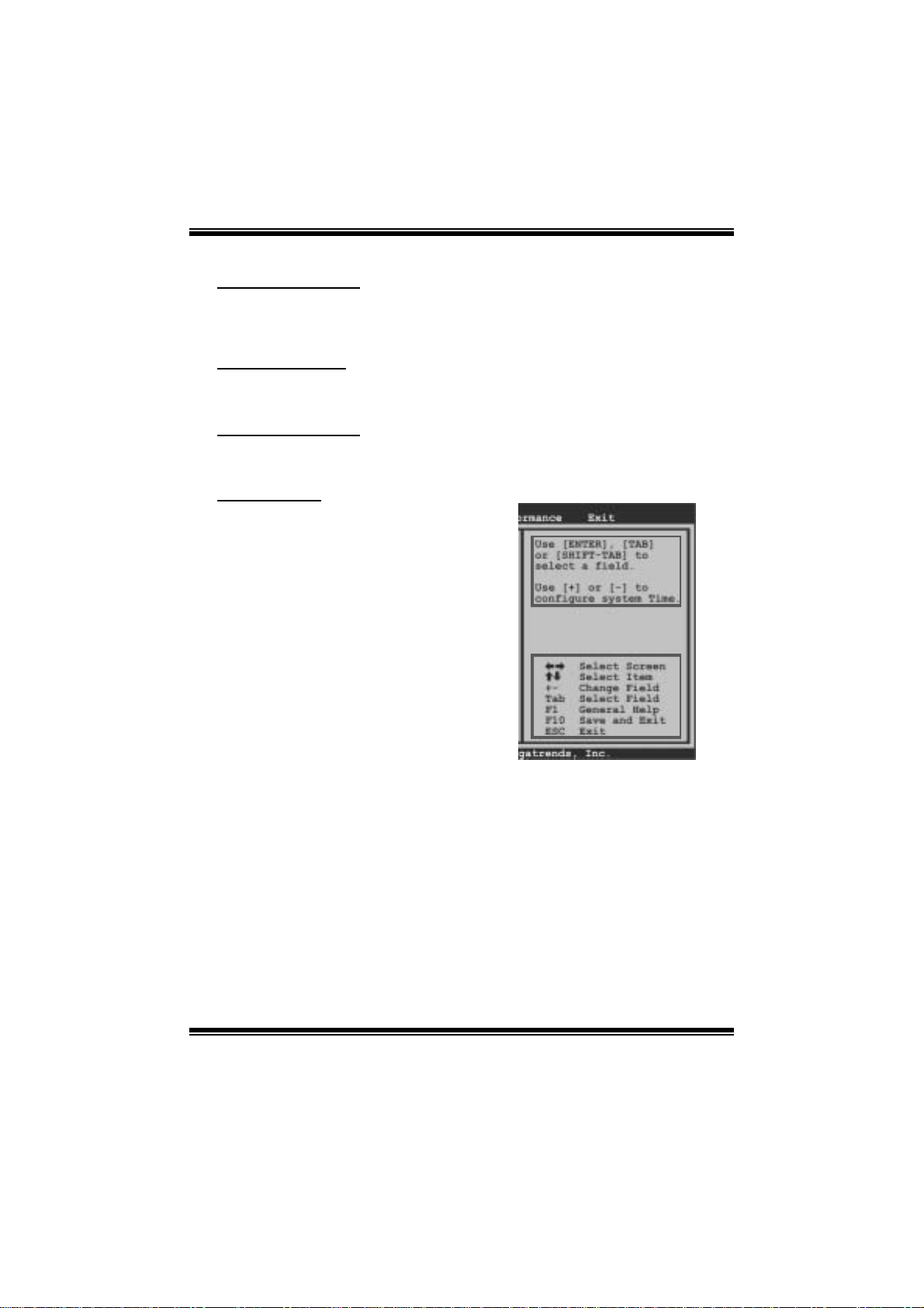
Using Setup
When starting up the computer, press
<Del> during the Power-On Self-Test
(POST) to enter the BIOS setup utility.
In the BIOS setup utility, you will see
General Help description at the top right
corner, and this is providing a brief
description of the selected item.
Navigation Keys for that particular menu
are at the bottom right corner, and you can
us e th ese key s t o sel ect item and ch ange
the settings.
Notice
z T he default BIOS settings apply for most conditions to ensure optimum perform ance
of the motherboard. If the system becomes unstable after changing any settings,
please load the default settings to ensure system’s compatibility and stability. Use
Load Setup Default under the Exit Menu.
z For better system perform ance, the BIOS firmwa re is being continuously updated.
T he BIOS inform ation described in this manual is for your reference only. The actual
BIOS informat ion and settings on board may be slightly differ ent from this manual.
z T he content of this manual is subject to be chang ed without notice. W e will not be
responsible for any mist akes found in this user’s manual and any system damage that
may be caused by wrong-settings.
General Help
Navigation Keys
2
Page 4
G41- M7 BIOS Manual
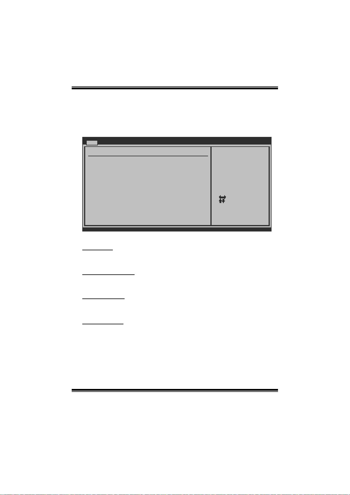
1 Main Menu
Once you enter AMI BIOS S etup Utility, the Main Menu will appear on the screen
providing an overview of the basic system information.
Main Advanced PCIPnP Boot Chipset Performance
System Overview
AMI BIOS
Version :01.01.0 1
Build Date:01/01/0 9
System Memory
Size :
System Time 00
System Date [Thu 01/01/20 09]
Floppy A
> IDE Configuratio n
vxx.xx (C)Copyright 198 5-200x, American Megatre nds, Inc.
AM I BI O S
Shows system informati on including BIOS version, built date, etc.
BIOS SETUP UTILITY
[ :00:00]
Exit
Use [ENTER], [TA B]
or [SHIFT-TAB] t o
select a field.
Use [+] or [-] t o
configure system Time.
Select Screen
Select Item
Change Field
+-
Select Field
Tab
General Help
F1
Save and Exit
F10
Exit
ESC
System Memory
Shows system memory size, VGA shard memory will be excl uded..
System Time
Set the system internal clock.
System Date
Set the system date. Note that the ‘Day’ automatically changes when you set the
date.
3
Page 5

G41- M7 BIOS Manual
Floppy A
Select the type of floppy disk dri ve inst alled in your syst em.
Options: 360K, 5. 25 in / 1.2M, 5.25 in / 720K, 3.5 i n / 1.44M, 3.5 in /
2.88M, 3.5 in / None
IDE Configuration
The BIOS wi ll aut o mati cal l y detect t h e presen c e o f ID E / SAT A devices . Th ere i s a
su b-menu fo r each IDE/S AT A dev ice. S elect a dev ice and press <En ter> to ent er
the sub-menu of detailed opt ions.
Main
IDE Confuguration
ATA/IDE Configurat ion [Enhanced]
Configure SATA C hannels [Before PATA]
Legacy IDE Chann els [SATA Pri, PA TA Sec]
> SATA1 Device
>
SATA2 Device
> IDE Channel 1 Ma ster
> IDE Channel 1 Sl ave
Hard Disk Write Pr otect [Disabled]
IDE Detect Time Ou t (Sec) [35]
BIOS SETUP UTILITY
Options
Disabled
Compatible
Enhanced
Select Screen
Select Item
Go to Sub Scr een
Enter
General Help
F1
Save and Exit
F10
Exit
ESC
vxx.xx (C)Copyright 198 5-200x, American Megatre nds, Inc.
ATA/ IDE Configura tion
T his item allows you to control the onboard IDE controller.
Options: Enhanced (Default) / Compatible / Disabled
Configure SATA Cha nne l s
T his item allows you to control the SATA channel configuration sequence.
Options: Before P ATA (Default) / Behind PAT A
Legacy IDE Channels
T his item appears only when “ATA/IDE Configuration” is set to “Compatible”.
Options: SAT A Pri, PAT A Sec (Default) / SATA Only / PAT A Pri, SATA Sec /
PATA Only
4
Page 6
G41- M7 BIOS Manual
SATA1/2 Device; IDE Channel 1 Master/Slave
Main
SATA1 Device
Device :
Type [Auto ]
LBA/Large Mode [Auto ]
Block (Multi-S e ctor Transfer)[Auto ]
PIO Mode [Auto ]
DMA Mode [Auto ]
S.M.A.R.T [Auto ]
32Bit Data Tra n sfer [Enab led]
vxx . xx (C)Copyright 1985-200x, American Me g atrends, Inc.
BIOS SETU P UTILITY
Select the type
of device connected
to the system.
Se lect Screen
Se lect Item
Ch ange Option
+-
Ge neral Help
F1
Sa ve and Exit
F10
Exit
ESC
The BIOS detects the information and values of respective devices, and these
information and values are shown bel ow t o the name of the sub-menu.
Type
Select the type of the IDE/SAT A drive.
Opti ons: Auto (De faul t ) / C D/DVD / AR M D / Not Ins talled
LBA/Large Mode
Enable or disable the LB A mode.
Options: Auto (Default) / Disabled
Block (Multi-Sector Transfer)
En able o r d i s abl e mu l ti -s ect o r t ransfer .
Options: Auto (Default) / Disabled
PIO Mode
Select the PIO mode.
Options: Auto (Default) / 0 / 1 / 2 / 3 / 4
DMA Mode
Select the DMA mode.
Options: Auto (Default) / Disabled
5
Page 7

G41- M7 BIOS Manual
S.M.A.R.T
Set the Smart Moni toring, Analys is, and Reporting T echnology.
Options: Auto (Default) / Disabled / Enabled
32Bit Data Trans fer
Enable or disable 32-bit data transfer.
Options: Enabled (Default) / Disabled
Har d Disk Wr i te P r otect
Disable or enable device write protection. This will be effective only if the device
is accessed through BIOS .
Options: Disabled (Default) / Enabled
IDE Detect Time Out (Sec)
Select the time out value for detecting IDE/S ATA devi ces.
Options: 35 (Default) / 30 / 25 / 20 / 15 / 10 / 5 / 0
6
Page 8
G41- M7 BIOS Manual
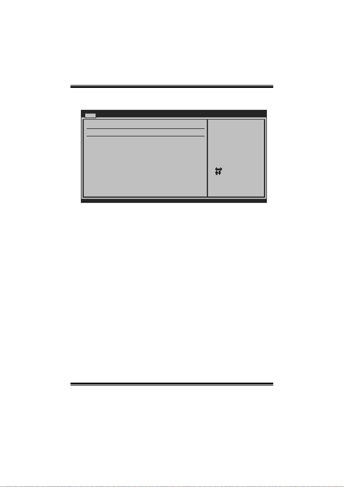
2 Advanced Menu
T he Advanced Menu all ows you to configu re the settings of C PU, S uper I/O, P ower
Management, and other system devices.
Notice
z Beware of that setting inappropriate values in items of this menu may cause
system to malfuncti on.
Main Advanced PCIPnP Boot Chipset Performance
WARNING: Setti n g wrong values in below sections
may c a use system to malfunction.
> CPU Configur a tion
> SuperIO Conf i guration
> Hardware Hea l th Configuration
> Smart Fan Co n figuration
> Power Config u ration
> USB Configur a tion
BIOS SETU P UTILITY
Configure CPU.Advanced Setti n gs
Exit
Se lect Screen
Se lect Item
Go to Sub Screen
Enter
Ge neral Help
F1
Sa ve and Exit
F10
Exit
ESC
vxx . xx (C)Copyright 1985-200x, American Meg atrends, Inc.
CPU Configuration
T his item shows the CPU information that the BIOS automatically detects.
Advanced
Configure advanced CPU setting s
Module Version:xx. xx
Manufacturer:Intel
Frequency :
FSB Speed :
Cache L1 :
Cache L2 :
Ratio Actual Value :
Hardware Prefetche r [Enabled]
Adjacent Cache Lin e Prefetch [Enabled]
Max CPUID Value Li mit [Disabled]
Intel(R) Virtualiz ation Tech [Enabled]
Execute-Disable Bi t Capability [Enabled]
PECI [Disabled]
Core Multi-Process ing [Enabled]
vxx.xx (C)Copyright 198 5-200x, Amer ican Megatrends, Inc.
BIOS SETUP UTILITY
7
For UP platforms ,
leave it enabled .
For DP/MP server s,
it may use to tu ne
performance to t he
specific applica tion.
Select Screen
Select Item
Change Option
+F1
General Help
F10
Save and Exit
ESC
Exit
Page 9

G41- M7 BIOS Manual
Hardware Prefetcher
The proces s o r has a h ardware p re f et cher t h at autom at i cal l y anal yzes it s req u irem en t s
and pre fet ch es dat a an d in s t ru ct ion s fro m th e memo ry i n t o th e Lev el 2 cach e that are
likely to be required in the near future. This reduces the latency associated with
m emory read s.
Options: Enabled (Default) / Disabled
Adjacent Cache Line Prefetch
The processor has a hardware adjacent cache line prefetch mechanism that
aut o mat i cal l y fet ch es an ext ra 6 4-byt e cach e l i n e when ever t he p ro cesso r requests for
a 64-byte cache line. This reduces cache latency by making the next cache line
immediately available if the processor requires it as well.
Options: Enabled (Default) / Disabled
M ax CPUI D Val ue Lim i t
When the computer is booted up, the operating system executes the CPUID
instruction to identify the processor and its capabilities. Befo re it can do so, it must
first query the processor to find out the highest input value CPUID recognizes. This
determines the kind of bas ic information C P UID can provide the operating system.
Options: Disabled (Default) / Enabled
Intel(R) Virtua lization Te c h
Virtualization T echnology can virtually separate your system resou rce into seve ral
parts, thus enhance the performance when running virtual machines or multi
interfa ce systems.
Options: Enabled (Default) / Disabled
Execute-Disa ble Bit Capability
T his item allows you to configure th e Execut e Disabled Bit function, which protects
your system from buffer overflow attacks.
Options: Enabled (Default) / Disabled
PECI
T his item allows you to control the P ECI function for the processor which supports
Platform Environment C ontrol Int erface for bett er thermal m anagement.
Options: Disabled (Default) / Enabled
8
Page 10

G41- M7 BIOS Manual
Core M ulti-Proc e ssing
T his item allows multi-processing fun ction for multi-cor e processors.
Options: Enabled (Default) / Disabled
S uperIO Co n f i g ura ti o n
Advanced
Configure ITE8712 Super IO Chipset
Onboard Floppy Con troller [Enabled]
Parallel Port Addr ess [378]
Parallel Port Mo de [Normal]
Parallel Port IR Q [IRQ7]
Keyboard PowerOn [Disabled]
Mouse PowerOn [Disabled]
Restore on AC Powe r Loss [Power Off]
BIOS SETUP UTILITY
Allows BIOS to E nable
or Disable Flopp y
Controller
Select Screen
Select Item
Change Option
+-
General Help
F1
Save and Exit
F10
Exit
ESC
vxx.xx (C)Copyright 198 5-200x, American Megatre nds, Inc.
Onboard Floppy Controller
Select enabled if your system has a floppy disk controller (FDC) installed on the
system board and you wish to use i t. If you installed another FDC or the system uses
no floppy dri ve, select disabled in this field.
Options: Enabled (Default) / Disabled
Parallel Port Address
Thi s i tem al lows y ou t o deter m ine acces s onboard parallel port controller with which
I/O Address.
Options: 378 (Default) / 278 / 3B C / Disabled
Parallel Port M ode
T his item allows you to determine how the parallel port shoul d functi on.
Options: Normal (Default) Using Parallel port as Standard P rinter P ort.
EPP Using Parallel Port as Enhanced Parallel Port.
ECP Using Parallel port as Extended Capabilities Port.
ECP +EPP Using P arallel port as ECP & EPP mode.
9
Page 11

G41- M7 BIOS Manual
ECP Mode DM A Channel
T his item allows you to select parallel port ECP DMA.
Opti ons: DMA3 (De fault) / DMA0 / DMA1
Parallel Port IRQ
T his item allows you to select the IRQ for the onboard parallel port.
Options: IRQ7 (Default) / IRQ5 / Disabled
Keyboard Powe rO n
T his item allows you to control the keyboard power on funct ion.
Options: Disabled (De fault) / S pecifi c Key / Stroke Key / Any Key
Specific Key Enter
T his item will show only when Keyboard P owerOn is set “Specific Key.”
Stroke Keys Selected
T his item will show only when Keyboard P owerOn is set “Stroke Key.”
Options: Ctrl+ F1 (Default) / Wake Key / Power Key / Ctrl+F 2 / Ctrl+F3 /
C t rl +F 4 / Ct rl + F5 / Ct rl+F 6
Mouse PowerOn
T his item allows you to control the mouse power on function.
Options: Disabled (Default) / Enabled
Restor e on AC Power Loss
T his setting specifies how your system should behave a fte r a power fail or interrupts
occurs. By choosing Disabled will leave the computer in the power off state.
Choosing Enabled will restore the system to the status before power failure or
interrupt occurs.
Options: Power O ff (Default) / Power ON / Last State
10
Page 12

G41- M7 BIOS Manual
Hardware Health Configuration
T his item shows the system temperat ure, fan speed, and voltage information.
Advanced
Hardware Health Co nfiguration
H/W Health Functio n [Enabled]
Shutdown Temperatu re Function[Disabled]
CPU Temperature
SYSTEM Temperature
CPU Fan
System1 Fan
CPU Vcore
NB Voltage
+3.30V
+5.00V
+12.0V
FSB Voltage
DDR Voltage
5VSB
vxx.xx (C)Copyright 198 5-200x, American Megatre nds, Inc.
H/W Health Function
If with a monitoring system, the system will show PC health status during POST
stage.
Options: Enabled (Default) / Disabled
Shutdown Temperature Function
BIOS SETUP UTILITY
Enables Hardware
Health Monitorin g
Device.
Select Screen
Select Item
Change Option
+-
General Help
F1
Save and Exit
F10
Exit
ESC
T his item allows you to set up the CPU shutdown Temperature. This item is only
effective under W indows 98 ACPI mode.
Options: Disabled (Default) / 60℃/140℉ / 6 5℃/149℉ / 70℃/158℉ / 7 5℃/167℉
/ 80℃/ 176℉ / 85℃/185℉ / 90 ℃/194℉
11
Page 13

G41- M7 BIOS Manual
Smart F an Configuration
Advan ced
Smart Fan Conf iguration
CPU Smart Fan [Dis abled]
Smart Fan Cali bration
Control Mode
Fan Ctrl OFF( C)
Fan Ctrl On(C )
Fan Ctrl Start value
Fan Ctrl Sensi tive
o
o
BIOS SETU P UTILITY
When you choice [Auto]
, please run the
calibration to define
the Fan parameters for
Smart Fan control
Select Screen
Select Item
Change Option
+-
General Help
F1
Save and Exit
F10
Exit
ESC
vxx .xx (C)Copyright 1985-200x, American Megatrends, Inc.
CPU Sm art Fan
This ite m allo ws you to control the CPU Smar t Fan functio n.
Options: Disabled (Default) / Auto
Sm art Fan Cali br ation
Choose this item and then the BIOS will auto test and detect the CPU/System fan
fun ctions and s how CPU/S ystem fan speed.
Control Mode
T his item provides several oper ation modes of the fan.
Options: Quiet / Performance / Manual
Fan Ctrl OFF(℃)
If the CP U/System T emperature is lower than the set value, FAN will turn off.
Options: 0~127 (℃) (Interval: 1℃)
Fan Ctrl On(℃ )
CPU/System fan starts to work under smart fan function when ar rive this set value.
Options: 0~127 (℃) (Interval: 1℃)
12
Page 14

G41- M7 BIOS Manual
Fan Ctrl S tart Val ue
When CPU/System temperature arriv es to the set value, the CPU/System fan will
work under Smart Fan Function mode.
Options: 0~127 (Interval: 1)
Fan Ctrl Sensiti ve
Increasin g t h e valu e w ill rai s e t he sp eed of CPU/ Sy s t em fan.
Options: 1~127 (Interval: 1)
Power Con figuration
Advanced
ACPI Settings
Suspend mode [S1(POS)]
Repost Video on S3 Resume [NO]
ACPI Version Featu res [ACPI v1.0]
ACPI APIC support [Enabled]
AMI OEMB table [Enabled]
Headless mode [Disabled]
Energy Lake Featur e [Disabled]
APIC ACPI SCI IRQ [Disabled]
USB Device Wakeup From S3/S4 [Disabled]
High Performance E vent Timer [Disabled]
PSI Control [Enabled]
Advanced Resume Ev ent Controls
Resume On Ring [Disabled]
Resume On PME# [Disabled]
Resume On RTC Al arm [Disabled]
vxx.xx (C)Copyright 198 5-200x, American Megatre nds, Inc.
Suspe nd m ode
BIOS SETUP UTILITY
Select the ACPI
state used for
System Suspend.
Select Screen
Select Item
Change Option
+-
General Help
F1
Save and Exit
F10
Exit
ESC
T he it em allows you to select the suspend type under the AC P I operating system.
Opt i ons : S1 (P OS ) (Defau lt ) P ower on Susp end
S3 (STR) Suspend to RAM
Auto POS+STR
Repost Video on S 3 Resume
T he item allows you to determine whether to invoke VGA B IOS post on S3/ST R
resume.
Options: No (Default) / Yes
13
Page 15

G41- M7 BIOS Manual
ACPI Version Features
The item al l o ws yo u to sel ect t he vers i o n of ACPI.
Options: ACPI v1.0 (Default) / ACP I v2.0 / ACP I v3. 0
ACPI AP I C support
This item is used to enable or disable the motherboard's APIC (Advan ced
Programmable Interrupt Controller). The APIC provides multiprocessor support,
more IRQs and faste r interrupt handling.
Options: Enabled (Default) / Disabled
AMI OEMB t able
Set this value to allow the ACPI B IOS to add a pointer to an OEMB table in the Root
Syst em Description T able (RS DT ) table.
Options: Enabled (Default) / Disabled
Headless mode
This is a server-specific feature. A headless server is one that operates without a
keyboard, monitor or mouse. To run in headless mode, both BIOS and operating
system (e.g. Windows Server 2003) must support headless operation.
Options: Disabled (Default) / Enabled
Energy Lake Feature
T his item allows you control t he energy lake featur e.
Options: Disabled (Default) / Enabled
APIC ACPI SCI IRQ
Options: Disabled (Default) / Enabled
USB Device Wakeup from S3/S4
T his item allows you to enable or disabled the USB resume from S 3/S4 function.
Options: Disabled (Default) / Enabled
14
Page 16

G41- M7 BIOS Manual
High Performance Ev ent Timer
T his item allows you to enable or disabled the HPET.
Options: Disabled (Default) / Enabled
HPET Memory Address
T his item allows you to set the memory address of HPET .
Options: F ED00000h (Default) / FED01000h / FED02000h / FED03000h
PSI C on t ro l
This item allows you to control power supply of CPU for the purpose of saving
energy.
Options: Enabled (Default) / Disabled
Resume On Rin g
T his item allows you to control the wake on ring function.
Options: Disabled (Default) / Enabled
Resume On P ME#
W hen you select Enabled, a PME signal from PCI card ret urns the system to Full ON
state. F or this function to work, you may need a LAN add-on card which supports
the Wake on LAN function. S et the Wake on LAN (WOL) jumper on motherboard
to enabl e i f app l i cab l e.
Options: Disabled (Default) / Enabled
Resume On RTC Alarm
When “ Enabled”, you can set the date and time at which the RTC (real-time clock)
alar m awaken s th e sy s tem from S u s pen d mod e.
Options: Disabled (Default) / Enabled
RTC Alarm Da te (D ays )
You can choose which date the system will boot up.
RTC Ala r m Time
You can choose the system boot up time, input hour, minute and second to specify.
15
Page 17

G41- M7 BIOS Manual
USB Configuration
T his item shows the USB controll er and using USB device information.
Advanced
USB Configuration
Module Version - 2 .24.3-13.4
USB Devices Enable d:
Legacy USB Support [Enabled]
USB 2.0 Controller Mode [HiSpeed]
BIOS EHCI Hand-Off [Enabled]
> USB Mass Storage Device Configuration
BIOS SETUP UTILITY
Options
Disabled
Enabled
Auto
Select Screen
Select Item
Change Option
+-
General Help
F1
Save and Exit
F10
Exit
ESC
vxx.xx (C)Copyright 198 5-200x, American Megatre nds, Inc.
Legacy USB Support
T his item determines if the BIOS should provide legacy support fo r USB devices
li ke the key board, mouse, an d USB d rive. Thi s is a us eful fe ature when u si ng s uch
USB devices with operating systems that do not natively support USB (e.g.
Microso ft DOS or Windows NT).
Options: Enabled (Default) / Disabled / Auto
USB 2.0 Controller Mode
T his item allows you to select the operation mode of the USB 2.0 controller.
Options: HiSpeed (Default) US B 2.0-480Mbps
FullSpeed USB 1.1-12Mbps
BIO S EHCI Hand-Off
This item allows you to enable support for operating systems without an EHCI
hand-off featur e.
Options: Enabled (Default) / Disabled
16
Page 18

G41- M7 BIOS Manual
US B Mass St or ag e De vice C o n f ig ur at io n
Advanced
USB Mass Storage Device Configuration
USB Mass Storage Reset Delay [20 Sec]
Device #
Emulation Type [Auto]
vxx.xx (C)Copyright 1985-200x, American Megatrends, Inc.
BIOS SETUP UTILITY
Number of seconds
POST waits for the
USB mass storage
device after start
unit command.
Select Screen
Select Item
Change Option
+-
General Help
F1
Save and Exit
F10
Exit
ESC
USB Mass Storage Reset Delay
T his item allows you to set the reset delay for USB mass storage device.
Op t i ons : 20 Sec (D efau l t ) / 1 0 S ec / 30 Sec / 40 S ec
E m ula ti o n T ype
T his item allows you to select the emulation type of t he USB mass storage device.
Options: Auto (Default) / Floppy / Forced FDD / Hard Disk / CDROM
17
Page 19

G41- M7 BIOS Manual
3 PCIPnP Menu
T his section describes con figuring the PCI bus system. PC I, or Personal Computer
Interconnect, is a system which allows I/O devices to operate at speeds nearing the
speed o f the CPU itself uses when communicating with its own special components.
Notice
z Beware of that setting inappropriate values in items of this menu may cause
system to malfuncti on.
Main Advanced PCIPnP Boot Chips et T-Series
Advanced PCI/PnP S ettings
WARNING: Setting w rong values in below sec tions
may cause system to m alfunction.
Clear NVRAM [ No]
Plug & Play O/S [ No]
PCI Latency Timer [ 64]
Allocate IRQ to PC I VGA [ Yes]
Palette Snooping [ Disabled]
PCI IDE BusMaster [ Enabled]
IRQ3 [ Available]
IRQ4 [ Available]
IRQ5 [ Available]
IRQ7 [ Available]
IRQ9 [ Available]
IRQ11 [ Available]
vxx.xx (C)Copyright 198 5-200x, Amer ican Megatre nds, Inc.
BIOS SETUP UTILITY
Exit
Clear NVRAM duri ng
System Boot.
Select Screen
Select Item
Change Option
+-
General Help
F1
Save and Exit
F10
ESC
Exit
Clear NVRAM
T his item allows you to clear the data in the NVRAM (CMOS) by sel ecting “Yes”.
Options: No (Default) / Yes
Plug & Play OS
When set to YES, B IOS will only initialize the P nP cards used for the boot sequen ce
(VGA, IDE, SCSI). The rest of the cards will be initialized by the PnP operating
system like Window™ 95. When set to NO, BIOS will initialize all the PnP cards.
For non-PnP operating systems (DOS, Netware™), this option m ust set to NO.
Options: No (Default) / Yes
18
Page 20

G41- M7 BIOS Manual
PCI Latency Tim er
T his item controls how long a PCI device can hold the P CI bus befor e anothe r takes
over. T he longer the latency, the longer the PCI device can retain control of the bus
before handing it over to another PCI device.
Options: 64 (Default) / 32 / 96 / 128 / 160 / 192 / 224 / 248
Allocate IRQ to P CI VGA
T his item allows B IOS to choose a IR Q to ass ign for the PCI VGA card.
Opti ons: Yes (De fault) / No
Palette Snooping
Som e old graphic controllers need to “snoop” on the VGA palette and then map i t to
their display as a way to provide boot information and VGA compat ibility. This item
allows such snooping to take place.
Options: Disabled (Default) / Enabled
PCI IDE BusMaster
T his item is a toggle for the built-in driver that allows the onboard IDE controller to
perform D M A (Direct Memo ry Acc es s ) trans fers .
Options: Enabled (Default) / Disabled
IRQ3/4/5/7/9/10/11/14/15
T hese items will allow you to assign each system interrupt a type, depending on the
type of device using the interrupt. The option “Available” means the IRQ is going
to assign automatically.
Options: Available (Default) / Reserved
DMA Channel 0/1/3/5/6/7
T hese items will allow you to assign each DMA channel a type, depending on the
type of device using the channel. The option “ Available” means the channel is
going to assign automatically.
Options: Available (Default) / Reserved
R eserv ed Memo ry Siz e
T his item allows BIOS to reserve certain memory size for speci fic PC I device.
Options: Disabled (Default) / 16K / 32K / 64K
19
Page 21

G41- M7 BIOS Manual
4 Boot Menu
T his menu allows you to setup the system boot options.
Main Advanced PCIPnP Boot Chipset Performance
Boot Settings
> Boot Device Priority
> Hard Disk Dr ives
> Removable Dr ives
> CD/DVD Drive s
> Boot Setting s Configuration
BIOS SETU P UTILITY
Exit
Specifies the
Boot Device
Priority sequence.
Select Screen
Select Item
Enter
Go to Sub Screen
F1
General Help
F10
Save and Exit
ESC
Exit
vxx .xx (C)Copyright 1985-200x, American Me gatrends, Inc.
Boot De vice Priority
Items in this sub-menu specify the boot device priority sequence from the available
devices. The number of device items that appears on the screen depends on the
number of devi ces installed in the s ystem.
Hard Disk Drives
T he BIOS will att empt to arrange th e hard dis k boot sequence aut om ati cally. You
can also ch an ge th e b o oti n g s equen ce. The n u mber of device i t ems t h at ap p ears o n
the screen depends on the number of devices installed in the system.
Re mo va ble Dr ives
T he BIOS will att empt to arrange the removabl e dri ve bo ot sequence automaticall y.
You can also change the booting sequence. The number of device items that
appears on the screen depends on the number of devic es installed in the system.
20
Page 22

G41- M7 BIOS Manual
CD/DV D Drives
T he BIOS will attempt to arrange the CD/DVD drive boot sequence automatically.
You can also change the booting sequence. The number of device items that
appears on the screen depends on the number of devic es installed in the system.
Boot Settings Configuration
BIOS SETUP UTILITY
Boot
Boot Settings Conf iguration
Quick Boot [ Enabled]
Full Screen LOGO S how [ Enabled]
AddOn ROM Display Mode [ Force BIOS]
Bootup Num-Lock [ ON]
Interrupt 19 Captu re [ Disabled]
BOOT SUCCESS BEEP [ Enabled]
Allows BIOS to s kip
certain tests wh ile
booting. This wi ll
decrease the tim e
needed to boot t he
system.
Select Screen
Select Item
Change Option
+F1
General Help
Save and Exit
F10
Exit
ESC
vxx.xx (C)Copyright 198 5-200x, Amer ican Megatre nds, Inc.
Quick Boot
Enabling this option will cause an abridged version of the Power On Self-Test
(POST) t o execute a fter you power up the computer.
Options: Enabled (Default) / Disabled
Full Scr een LOGO Show
T his item allows you to enable/disable Full Screen LOGO Show function.
Options: Enabled (Default) / Disabled
AddOn ROM Display Mode
T his item sets the display mode for option ROM.
Op t i ons : Force B IO S (Defaul t) / Keep Cu rren t
21
Page 23

G41- M7 BIOS Manual
Bootup Num-Loc k
Selects the NumLock State after the system switched on.
Options: ON (Default) / OFF
Interrupt 19 Capture
Interrupt 19 is the software interrupt that handles the boot di sk funct ion. W hen set to
Enabled, this item allows the option ROMs to trap interrupt 19.
Options: Disabled (Default) / Enabled
BOOT SUCCESS BEEP
W hen this item is set to Enabled, BIOS will let user know boot success with beep.
Options: Enabled (Default) / Disabled
22
Page 24

G41- M7 BIOS Manual
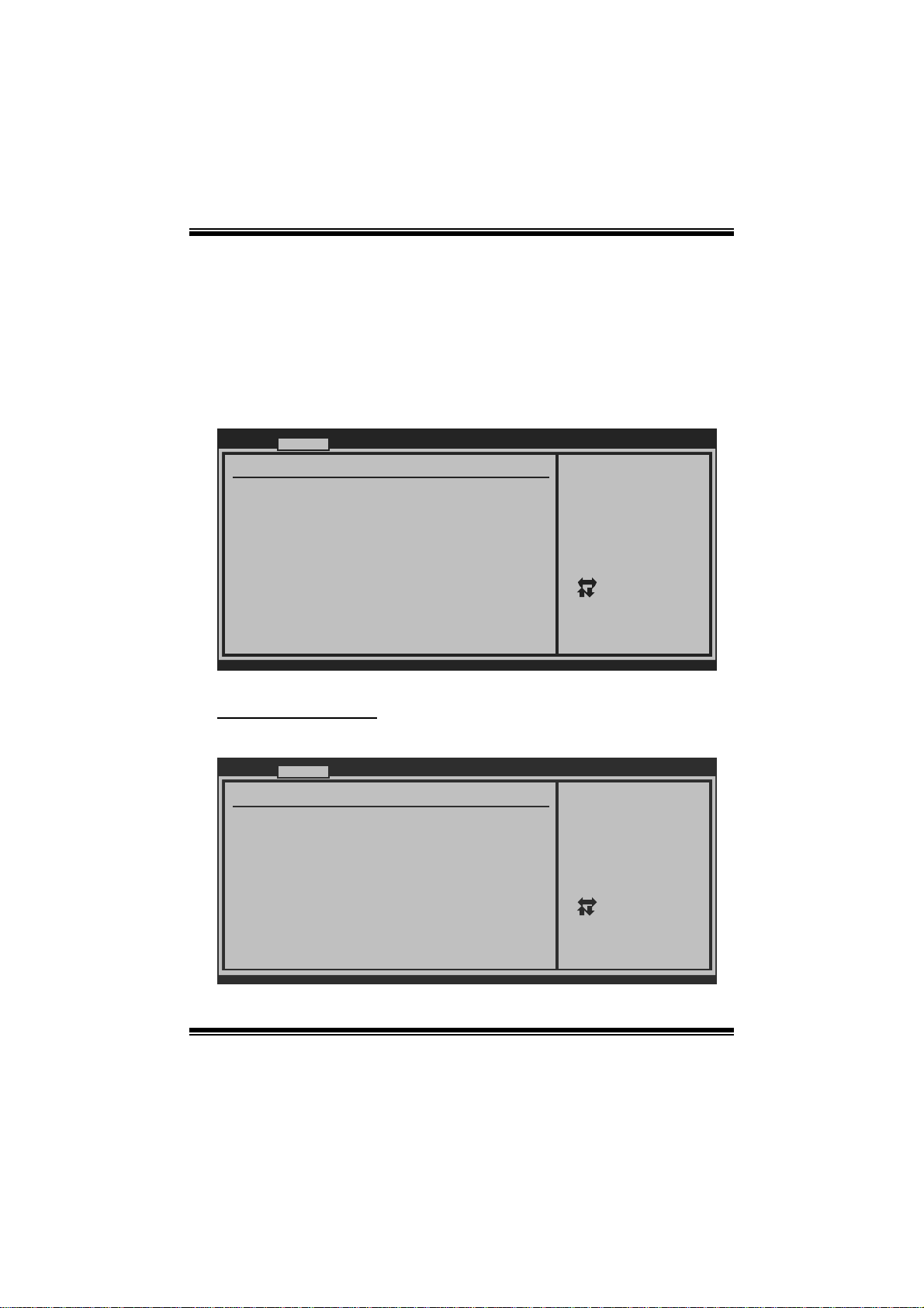
5 Chipset Menu
Thi s s u b m en u all o w s you to co nfi g u re t he sp eci fic featu res of t he chip s et i n stal led o n
your system. This chipset manage bus speeds and access to system memory
resources, such as DRAM. It also coordinat es communicat ions with the P C I bus.
Notice
z Beware of that setting inappropriate values in items of this menu may cause
system to malfuncti on.
Main Advanced PCIPnP Boot Chipset Performance
Advanced Chips et Settings
WARNING: Setti ng wrong values in below sections
may c ause system to malfunction.
> North Bridge Configuration
> South Bridge Configuration
BIOS SETU P UTILITY
Configure North Bridge
features
Exit
Select Screen
Select Item
Enter
Go to Sub Screen
F1
General Help
F10
Save and Exit
ESC
Exit
vxx .xx (C)Copyright 1985-200x, American Me gatrends, Inc.
23
Page 25

G41- M7 BIOS Manual
North Br idge Confi gur ation
BIOS SETUP UTILITY
North Bridge Chips et Configura tion
Memory Remap Featu re [Enabled]
PCI MMIO Allocat ion:
Initiate Graphic A dapter [PEG/PCI]
Internal Graphics Mode Select [Enabled,32 MB]
IGD GTT Graphics m emory size [No VT mode , 2MB]
PAVP Mode [Lite]
PEG Port Configura tion
PEG Port [Auto]
> Video Function C onfiguration
vxx.xx (C)Copyright 198 5-200x, Amer ican Megatre nds, Inc.
Chipset
ENABLE: Allow
remapping of
overlapped PCI m emory
above the total
physical memory.
DISABLE: Do not allow
remapping of mem ory.
Select Screen
Select Item
Change Option
+-
General Help
F1
Save and Exit
F10
ESC
Exit
M emory Re ma p Feature
This item allows you to enable or disable the remapping of the overlapped PCI
memory above the total phys ical memory. Only 64-bit OS supports this function.
Options: Enabled (Default) / Disabled
Initiate Graphic Adapte r
T his item allows you to enable or disable VGA control ler.
Options: PEG/PCI (Default) / IGD / PCI/IGD / PCI/PEG / P EG/IGD
Internal G raphics Mode Selec t
This item will be different as your memory modules. When the memory size is
decided, this frame buffer size will also be fixed.
Options: Enabled,32MB (Default) / Enabled,64MB / Enabled,128MB / Disabled
PAVP Mode
GMCH Protected Audio Video P ath (PAVP ) BIOS support.
Options: Lite (Default) / Disabled / High
24
Page 26

G41- M7 BIOS Manual
PEG Port
T his BIOS feature i s a toggl e that enables or disabl es the PCI Express port.
Options: Auto (Default) / Disabled
Vi deo Function Configura tion
BIOS SETUP UTILITY
Video Function Con figuration
DVMT Mode Select [DVMT Mode]
DVMT/FIXED Memory [2 56MB]
Chipset
This setting is only
Select Screen
Select Item
Change Option
+-
General Help
F1
Save and Exit
F10
ESC
Exit
vxx.xx (C)Copyright 198 5-200x, Amer ican Megatre nds, Inc.
DVMT Mode S elect
T his item allows you to select the DVMT mode.
Options: DVM T M ode (Default) / F ixed Mode
DVMT/FIXED Memory
DVMT stands for “ Dynamic Video Memory T echnology”. This is an enhancement
of the unified memory architecture (UMA) concept. DVMT will set the optimum
amount of memory to be allocated for a balance between graphics and system
perform ance. DVMT dynamically respond to system requirements and applications
demands, by allocating the proper amount of display, texturing and buffer m emory
after the oper ati ng system has boot ed.
Options: 256MB (Default) / 128MB / Maximum DVMT
25
Page 27

G41- M7 BIOS Manual
South Br idge Confi gura tion
BIOS SETUP UTILITY
South Bridge Chips et Configura tion
USB Functions [8 USB Port s]
USB 2.0 Controller [Enabled]
Audio Controller [Azalia]
Onboard Lan Contro l [Enabled]
Onboard Lan Boot R OM [Disabled]
Onboard Lan Order Boot Rom [PnP/BEV(BB S)]
MAC ID Information
SMBUS Controller [Enabled]
SLP_S4# Min. Asser tion Width [1 to 2 sec onds]
vxx.xx (C)Copyright 198 5-200x, Amer ican Megatre nds, Inc.
Chipset
Options
Disabled
2 USB Ports
4 USB Ports
6 USB Ports
8 USB Ports
Select Screen
Select Item
Change Option
+-
General Help
F1
Save and Exit
F10
ESC
Exit
USB Func tions
T he it em determ ines the number of functional USB port.
Options: 8 USB Ports (Default) / 6 USB Ports / 4 USB Ports / 2 USB Ports /
Disabled
USB 2.0 Controller
T his entry is to enabled/ di sabled EHCI controller only. This Bios itself may/may not
have high speed USB support. If the Bios has high speed USB support built in,the
support will be automately turn on when high speed device were attached.
Options: Enabled (Default) / Disabled
Audio Control ler
T his item allows you to select the Audio support.
Options: Azalia (De fault) / All Disabled
Onboard Lan Control
T his item allows you to enable or disable the Onboard LAN.
Options: Enabled (Default) / Disabled
26
Page 28

G41- M7 BIOS Manual
Onboard Lan Boot Rom
T his item allows you to select the s tatus of Onboard LAN Boot R OM.
Options: Disabled (Default) / Enabled
Onboard Lan Order Boot Rom
Options: PnP/BEV(BBS ) (Default) / INT 18 / INT19
MAC ID Information
T his item shows the LAN MAC ID.
SMBUS Controller
T h i s B IO S fe at ure c o n t rols the I/ O buf fe rs fo r the SM Bus.
Options: Enabled (Default) / Disabled
SLP_S4# Min. Assertion Width
Options: 1 to 2 seconds (Default ) / 4 to 5 s econds / 3 to 4 seconds / 2 to 3 seconds
27
Page 29

G41- M7 BIOS Manual
6 Performance Menu
T his submenu allows you to change voltage and clock of various devices.
(However, we suggest you use the default setting. Changing the voltage and clock
improperly may damage the device.)
Notice
z Beware of that setting inappropriate values in items of this menu may cause
system to malfuncti on.
Main Advanced PCIPnP Boot Chips et Perfo rmance
Advance Performanc e Settings
WARNING: Please Cl ear CMOS if system no di splay
after ove rclocking.
Intel(R) SpeedStep (tm) tech [Enabled]
Ratio CMOS Setting [ x15.0]
CPU Frequency Sett ing
PCIE Clock By [Auto]
PCIE Frequency Set ting [100]
DRAM Frequency [Auto]
> ALL Voltage Conf iguration
Configure DRAM Tim ing by SPD [Enabled]
[200]
BIOS SETUP UTILITY
Exit
Disabled: Disabl e GV3
Enabled: Enable GV3
Select Screen
Select Item
Go to Sub Scr een
Enter
General Help
F1
Save and Exit
F10
ESC
Exit
vxx.xx (C)Copyright 198 5-200x, Amer ican Megatre nds, Inc.
I ntel(R) Speed St ep(tm) Tech
This item allows you to enable SpeedStep technology for better power saving.
SpeedStep is a technology built into some Intel processors that allows the clock
sp eed of th e proces s or to be d y nami cal ly chang ed by s o ft ware.
Options: Enabled (Default) / Disabled
Ra t io CM OS Se t ting
T his item allows you to set the CPU ratio frequ ency.
Options: x14 / x15 (Differed by CP U)
CPU Frequency Setting
T his item allows you to select the CPU Frequency.
Options: 200 (Default) / Min= 100MHz; Max= 800MHz
28
Page 30

G41- M7 BIOS Manual
PCIE Cl ock By
T his item allows you to select the PCIE clock control
Options: Auto (Default) / Manual
PCIE Fr eque nc y Set ti ng
T his item allows you to select the PCIE clock control
Options: 100 (Default) / Min=100; M ax=150
DRAM Freque ncy
T his item allows you to control the Memory Clock.
Options: Auto (Defaul t) /DDR2 667Mhz / DDR2 800M hz
ALL Volta ge Conf igur ation
BIOS SETUP UTILITY
Voltage Configurat ion
CPU Voltage [Default]
CPU GTL Ref Voltag e [0.67*VTT]
FSB Voltage [Default]
Chipset Voltage [Default]
MCH GTL Ref Voltag e [0.63*VTT]
Memory Voltage [1.950 V]
vxx.xx (C)Copyright 198 5-200x, Amer ican Megatre nds, Inc.
Performance
CPU Voltage Cont rol
+F1
F10
ESC
Select Screen
Select Item
Change Option
General Help
Save and Exit
Exit
CPU Volta ge
T his item allows you to select CP U Voltage Control.
Options: Default (Default) / +5% / +10% / +15%
CPU GTL Ref Volta ge
T his item allows you to select CP U GTL R ef Voltage Control.
Options: 0. 67*VTT (Default) / 0.65*VTT / 0.63*VT T / 0.615*VTT
29
Page 31

G41- M7 BIOS Manual
FSB Voltage
T his item allows you to select FS B Voltage Control.
Options: Default (Default) / +0.1V / +0.2V / +0.3V
Chipset Voltage
T his item allows you to select Chipset Voltage Control.
Options: Default (Default) / +0.1V / +0.2V / 0.3V
MCH GTL Ref Voltage
T his item allows you to select MCH GT L Ref Voltage Control.
Options: 0. 63*VTT (Default) / 0.61*VTT / 0.60*VT T
Memory Voltage
T his item allows you to select DDR Voltage Control.
Options: 1.950 V (Default) / 2.055 V / 2.153 V / 2.250 V / 2.557 V / 2.649 V /
2.742 V / 2.837 V
Configure DRAM Timing by SPD
Options: Enabled (Default) / Disabled
DRA M tCL
Options: 3 (De fault) / 3 ~ 7
DRAM t RAS
Options: 9 (De fault) / 9 ~ 24
DRA M tRP
Options: 3 (De fault) / 3 ~ 10
DRAM t RCD
Options: 3 (De fault) / 3 ~ 10
DRA M tWR
Options: 3 (De fault) / 3 ~ 15
30
Page 32

G41- M7 BIOS Manual
DRA M tRF C
Options: 15 (Default) / 15 ~ 78
DRA M tWTR
Options: 2 (De fault) / 2 ~ 15
DRAM t RRD
Options: 2 (De fault) / 2 ~ 15
DRA M tRTP
Options: 2 (De fault) / 2 ~ 15
31
Page 33

G41- M7 BIOS Manual
7 Exit Menu
This menu allows you to load the optimal default settings, and save or discard the
changes to the BIOS items.
Main Advanced PCIPnP Boot Chipset Performance
Exit Options
Save Changes a nd Exit
Discard Change s and Exit
Discard Change s
Load Optimal D efaults
BIOS SETU P UTILITY
Exit
Exit system setup
after saving the
changes.
F10 key can be used
for this operation.
> Security
vxx .xx (C)Copyright 1985-200x, American Me gatrends, Inc.
Select Screen
Select Item
Enter
Go to Sub Screen
F1
General Help
F10
Save and Exit
ESC
Exit
Save Changes and Exit
Save all configur ation changes to C MOS R AM and exit setup.
Di scard Changes and Exit
Abandon all changes made during the current sessi on and exit setup.
Di scard Changes
Abandon all changes made during the current session and restore the previously
saved values.
Load Optimal De faults
This selection allows you to reload the BIOS when problem occurs during system
booting sequence. These configurations are factory settings optimized for this
system.
32
Page 34

G41- M7 BIOS Manual
Security
T his sub-menu allows you t o provide/revise supervisor and us er password.
BIOS SETU P UTILITY
Exit
Security Setti ngs
Supervisor Pas sword :Not Installed
User Password :Not Installed
Change Supervi sor Password
User Access Le vel [Full Access]
Change User Pa ssword
Clear User Pas sword
Password Check [Setup]
Boot Sector Vi rus Protection [Disabled]
vxx .xx (C)Copyright 1985-200x, American Me gatrends, Inc.
Install or Change the
password.
Select Screen
Select Item
Change
Enter
General Help
F1
Save and Exit
F10
Exit
ESC
Change Supervi sor Password
Setting the supervisor password will prohibit everyone except the supervisor from
making changes using the CMOS Setup Utility. You will be prompted with to enter a
password.
User Acess Level
T his item allows supervisor to set the user level.
Op t i ons : Ful l Acces s (Defaul t) / N o Access / V iew On l y / Lim i t ed
Cha nge Us er Password
If the Supervisor Password is not set, then the User Password will function in the
same way as the Supervisor Password. If the Supervisor Pas sword is set and the User
Password is set, the “ User” will only be able to view configurations but will not be
abl e to ch an g e t hem.
Cle ar Use r Pa ssword
T his item is for clearing user passwo rd.
33
Page 35

G41- M7 BIOS Manual
P assw or d Check
T his item is for setting the timing that checking password.
Options: Setup (Default) / Always
Boot S e ctor Vi r us Protection
T his option allows you to choose the VIRUS Warning featur e that is used to protect
the IDE Hard Disk boot sector. I f this fun ction is enabled and an attempt is made to
write to the boot sector, BIOS will display a warning message on the screen and
sound an alarm beep.
Options: Disabled (Default) / Enabled
34
 Loading...