

Page 1

G41D3 + /G41D3G+ BIO S Manual
i
B IOS Set up.... ............ ............ ............ ............ ............ ............ ............ .........1
1 Main Me nu...............................................................................................3
2 Adv anc ed Menu...... ............ ............ ............ ............ ............ ............ .........7
3 PCIPnP Menu........................................................................................18
4 Boo t Men u..............................................................................................21
5 Chipse t Menu.........................................................................................24
6 Performance Menu...............................................................................29
7 Exit Menu...............................................................................................3 2
Page 2

G41D3 + /G41D3G+ BIOS Manual
BIOS Setup
Introduction
The purpose of this manual is to describe the settings in the AMI BIOS Setup
program on this motherboard. The S etup program allows users to modify the basic
system configuration and save these settings to CMOS RAM. The power of CMOS
RAM is supplied by a battery so that it retains the S etup information when the power
is turned off.
Basic Input-Output System (BIOS) determines what a computer can do without
acc essing programs from a disk. T his system controls most of the input and output
devices such as keyboard, mouse, serial ports and disk drives. BIOS activates at the
first stag e o f the booting proc ess, loading and executing the operating system. S om e
additional features, such as virus and password protection or chipset fine-tuning
options are also included in B IOS.
T he rest of this manual will to guide you through the options and settings in BIOS
Setup.
Plug and Play Support
T his AM I BIOS supports the P lug and Play Version 1. 0A specific ation.
EPA Green PC Support
T his AM I BIOS supports Version 1. 03 of t he EPA Green PC specification.
APM Support
This AMI BIOS supports Version 1.1&1.2 of the Advanced Power Management
(AP M) speci fic ati on. Power m anag ement fe atures a re im plemen ted via t he S ystem
Management Interrupt (SMI). Sleep and Suspend power management modes are
supported. Power to the hard di sk drives and video m onitors can also be m anaged by
this AMI BIOS.
ACPI Support
AMI ACPI BIOS support Version 1.0/2.0 of Advanced Configuration and Power
interface specifi cation (ACP I). It provides ASL code for pow er manag ement and
device configuration capabilities as defined in the ACPI specific ation, developed by
Microso ft, Intel and T oshiba.
1
Page 3
G41D3 + /G41D3G+ BIOS Manual
PCI Bus Support
T his AMI BIOS also supports Version 2.3 of the Intel PCI (Peripheral Component
Int erconn ect ) local b u s s p eci fic ati on .
DRAM Support
DDR3 SD R AM (Do uble Dat a Rate III Sy nch ron ous D R A M) is suppo rted .
Su ppor t e d CP Us
T his AM I BIOS supports the Intel CP U.
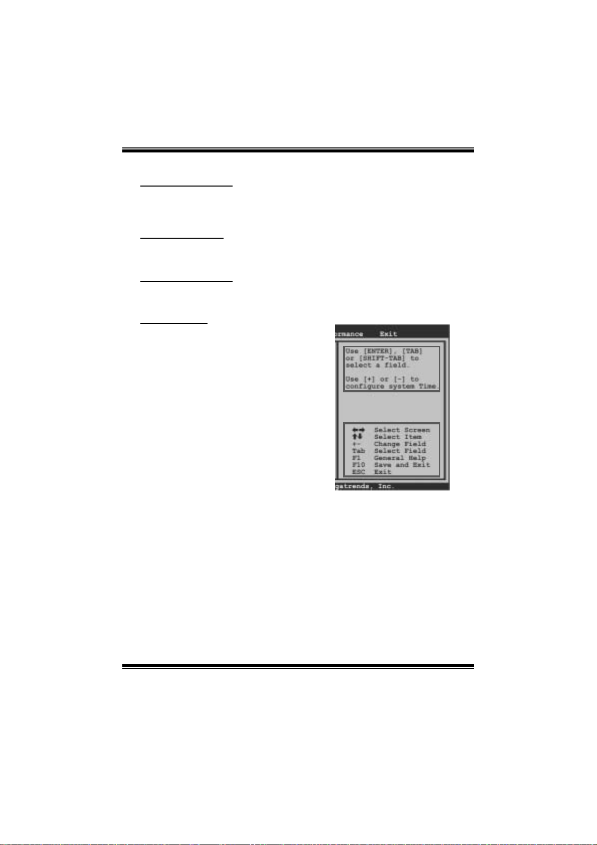
Using Setup
When starting up the computer, press
<Del> during the Power-On Self-Test
(POST) to enter the BIOS setup utility.
In the BIOS setup utility, you will see
General Help description at the top right
corner, and this is providing a brief
description of the selected item.
Navigation Keys for that particular menu
are at the bottom right corner, and you can
us e these keys to sele ct it em and ch ange
the settings.
Notice
z T he default BIOS settings apply for most conditions to ensure optimum performance
of the motherboard. If the system becomes unstable after changing any settings,
please load the default settings to ensure system’s compatibility and stability. Use
Load S etup Default under the Exit Menu.
z For better system per form ance, the BIOS firmware is being continuously updated.
T he BIOS information described in this manual is for your reference only. The actual
BIOS i nformat ion and settings on board may be s li ghtl y differ ent from this manual.
z T he content of this manual is subject to be changed without notice. W e will not be
responsible for any mistakes found in t his user’s manual and any system damage that
may be caused by wrong-settings.
General Help
Navigati on Keys
2
Page 4

G41D3 + /G41D3G+ BIOS Manual
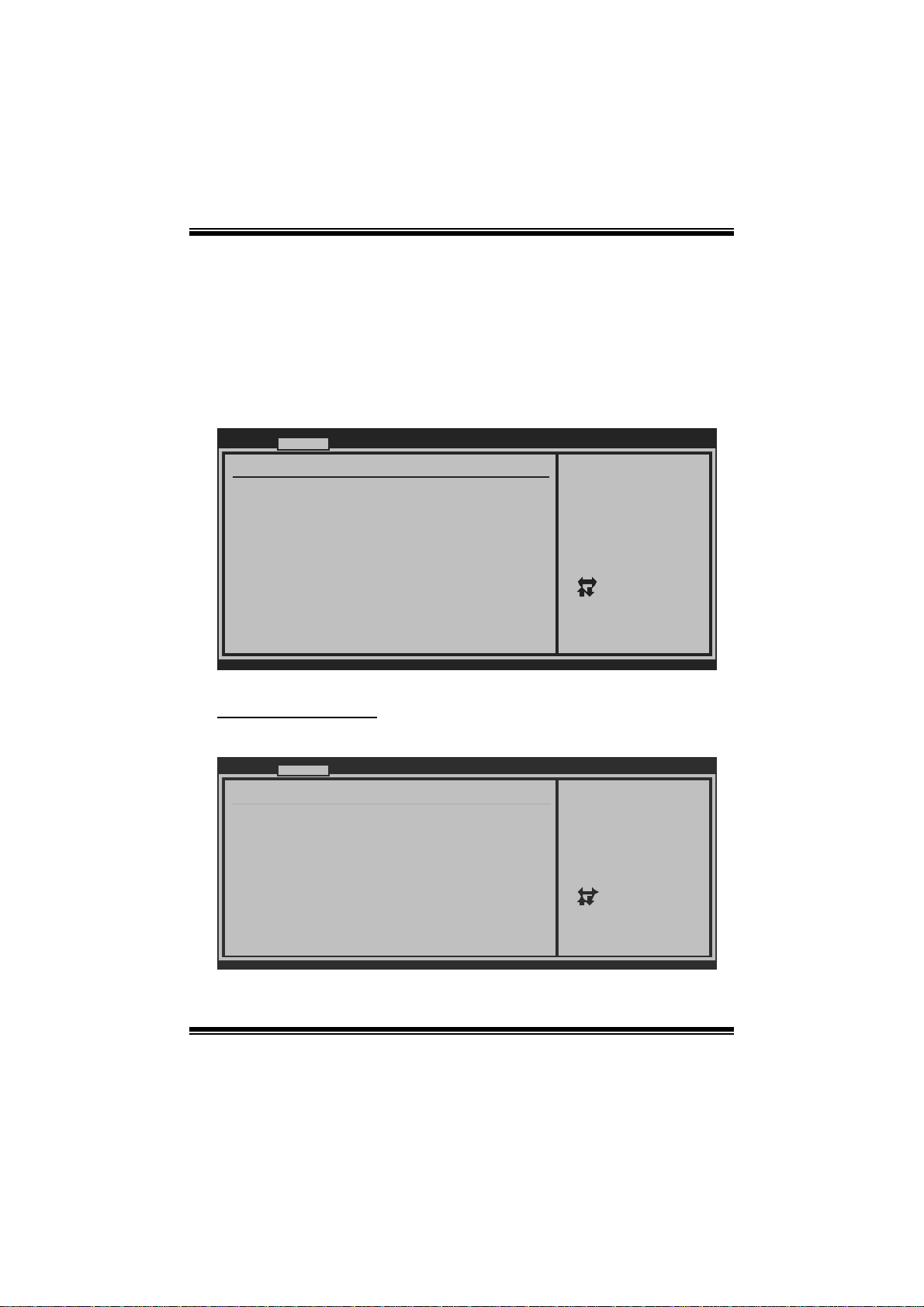
1 M ain Menu
Once you enter AMI BIOS S etup Utility, the Main Menu will appear on the screen
providing an overvi ew of the basic system information.
Main Advanced PCIPnP Boot Chipset Performance
System Overview
AMI BIOS
Version :01.01.01
Build Date:01/01/10
System Time 00
System Date [Fri 01/01/2010]
Floppy A
> IDE Configuration
vxx.xx (C)Copyright 1985-200x, American Megatrends, Inc.
AM I BIOS
BIOS SETUP UTILITY
[ :00:00]
Exit
Use [ENTER], [TAB]
or [SHIFT-TAB] to
select a field.
Use [+] or [-] to
configure system Time.
Select Screen
Select Item
Change Field
+-
Select Field
Tab
General Help
F1
Save and Exit
F10
Exit
ESC
Shows system information including BIOS version, built date, etc.
System Memory
Shows system memory size, VGA shard memory will be excluded..
System Time
Set the system internal clock.
System Date
Set the system date. Note that the ‘Day’ automatically changes when you set the
date.
Floppy A
Select the type of floppy disk dri ve installed in your syst em.
Options: 360K, 5.25 in / 1. 2M, 5.25 in / 720K, 3. 5 in / 1.44M, 3.5 in /
2.88M, 3.5 in / None
3
Page 5

G41D3 + /G41D3G+ BIOS Manual
IDE Configuratio n
Th e BIOS w i ll au t o m ati cal l y detect t h e presen c e o f ID E / SATA d evices . T her e i s a
su b-menu fo r each IDE/ SAT A device. Sel ect a device and press <Ent er> to enter
the sub-menu of detailed options.
Main
IDE Confuguration
ATA/IDE Configuration [ Enhanced]
Configure SATA Channels [ Before PATA]
Legacy IDE Channels [ SATA Pri, PA TA Sec]
> SATA1 Device
>
SATA2 Device
> SATA3 Device
> SATA4 Device
> IDE Channel 1 Master
> IDE Channel 1 Slave
Hard Disk Write Protect [ Disabled]
IDE Detect Time Out (Sec) [ 35]
BIOS SETUP UTILITY
Options
Disabled
Compatible
Enhanced
Select Screen
Select Item
Go to Sub Screen
Enter
General Help
F1
Save and Exit
F10
Exit
ESC
vxx.xx (C)Copyright 1985-200x, Amer ican Megatre nds, Inc.
ATA/IDE Configura ti on
T his i tem allows you to control t he onboard IDE controller.
Options: Enhanced (Default) / Compatible / Disabled
Configure SATA Cha nnels
T his i tem allows you to control t he SATA channel configuration sequence.
Options: B efo re PATA (Default) / Behind PATA
Legac y IDE Channels
T his item appears only when “ATA/IDE C onfiguration” is set to “ Compatible”.
Options: SATA Pri, PATA Sec (Default) / SATA Only / PAT A Pri, SATA Sec /
PAT A Only
4
Page 6

G41D3 + /G41D3G+ BIOS Manual
SATA1/2/3/4 Device; IDE Channel 1 M aster/Slave
Main
SATA1 Device
Device :
Type [Aut o]
LBA/Large Mode [Aut o]
Block (Multi-S ector Transfer)[Aut o]
PIO Mode [Aut o]
DMA Mode [Aut o]
S.M.A.R.T [Aut o]
32Bit Data Tra nsfer [Ena bled]
vxx .xx (C)Copyright 1985-200x, American Megatrends, Inc.
BIOS SETU P UTILITY
Select the type
of device connected
to the system.
Select Screen
Select Item
Change Option
+-
General Help
F1
Save and Exit
F10
Exit
ESC
The BIOS detects the information and values of respective devices, and these
information and values are shown below to the nam e of t he sub-menu.
Type
Select the type of the IDE/SAT A drive.
Opti ons: Auto (Default) / C D/DVD / ARM D / Not Install ed
LBA/Large Mode
Enabl e or di sable the LB A mode.
Options: Auto (Default) / Disabled
Block (Multi-S ector Transfer)
En able o r d i s ab l e m u l ti -s ect o r t ransfer.
Options: Auto (Default) / Disabled
PIO Mode
Select the P IO mode.
Options: Auto (Default) / 0 / 1 / 2 / 3 / 4
DMA Mode
Select the DMA mode.
Options: Auto (Default) / Disabled
5
Page 7

G41D3 + /G41D3G+ BIOS Manual
S.M.A.R.T
Set the Smart Monitoring, Analysis, and R eporting Technology.
Options: Auto (Default) / Disabled / Enabled
32Bit Data Tran sfer
Enabl e or di sable 32-bit data transfer.
Options: Enabled (Default) / Disabled
Har d Disk Wri te Pr otec t
Disable or enable device write protection. T his will be effective only if the device
is accessed through B IOS.
Options: Disabled (De fault) / Enabled
IDE Detect Time Out (Sec)
Select the time out value for detecting IDE/S ATA devices .
Options: 35 (De fault) / 30 / 25 / 20 / 15 / 10 / 5 / 0
6
Page 8
G41D3 + /G41D3G+ BIOS Manual
2 Advanced Menu
T he Advanced Menu allows you to configure the settings of C P U, Super I/O, Power
Management, and other sys tem devices.
Notice
z Beware of that setting inappropriate values in items of this menu may cause
system to malfuncti on.
Main Advanced PCIPnP Boot Chipset Performance
WARNING: Setti ng wrong values in below sections
may c ause system to malf unction.
> CPU Configur ation
> SuperIO Conf iguration
> Hardware Hea lth Configuration
> Smart Fan Co nfiguration
> Power Config uration
> USB Configur ation
BIOS SETU P UTILITY
Configure CPU.Advanced Setti ngs
Exit
Select Screen
Select Item
Go to Sub Screen
Enter
General Help
F1
Save and Exit
F10
Exit
ESC
vxx .xx (C)Copyright 1985-200x, American Megatrends, Inc.
CPU Configuration
T his item shows the CPU information that the BIOS automatically detects.
Advanced
Configure advanced CPU settings
Module Version:xx.xx
Manufacturer:Intel
Frequency :
FSB Speed :
Cache L1 :
Cache L2 :
Ratio Actual Value:
Intel(R) SpeedStep(tm) tech [Disabled]
Intel(R) C-STATE tech [Disabled]
CIE Support [Disabled]
Hardware Prefetcher [Enabled]
Adjacent Cache Line Prefetch [Enabled]
Max CPUID Value Limit [Disabled]
Execute-Disable Bit Capability[Enabled]
PECI [Enabled]
Core Multi-Processing [Enabled]
vxx.xx (C)Copyright 1985-200x, American Megatrends, Inc.
BIOS SETUP UTILITY
7
Disable: Disable GV3
Enable: Enable GV3
Select Screen
Select Item
+-
Change Option
F1
General Help
Save and Exit
F10
ESC
Exit
Page 9

G41D3 + /G41D3G+ BIOS Manual
In tel(R) S p eed Step(tm) Tech
This item allows you to enable SpeedStep technology for better power saving.
SpeedStep is a technology built into some Intel processors that allows the clock
sp eed of the proces s o r to b e d y nami cal l y chang ed by s o ftware.
Options: Disabled (De fault) / Enabled
Inte l(R) C-STATE Tec h
This item allows you to control the C-State power management functions of the
processor.
Options: Disabled (De fault) / Enabled
C1E Support
C1E is “Enhanced Halt State” function, this function helps to save power and
decr ease heat by lowering CPU frequency while the processor is not working.
Options: Disabled (De fault) / Enabled
Hardware Prefetcher
Th e proces s o r h as a h ard w ar e p refetch er t h at au t omat i call y anal y zes it s req uirem en t s
and pre fet ch es dat a and i ns t r uct io ns fr om t h e m emor y i n t o th e L ev el 2 cach e th at are
likely to be required in the near future. This reduces the latency associated with
m emory read s.
Options: Enabled (Default) / Disabled
Adj acent Cache Line Prefetch
The processor has a h ardware adjacent cache line prefet ch mechanism that
aut o mat i cal l y fet ch es an ext ra 6 4-by t e cach e l i n e whenev er t h e p ro ces s o r req uest s for
a 64-byte cache line. This reduces cache latency by making the next cache line
immediately available if the processor requir es it as well.
Options: Enabled (Default) / Disabled
M ax CPUI D Va l ue Li m i t
When the computer is booted up, the operating system executes the CPUID
instruction to identify the processor and its capabilities. Befo re it can do so, it must
first query the processor to find out the highest input value CPUID recognizes. T his
determines t he kind of basic information C P UID can provide the operating system .
Options: Disabled (De fault) / Enabled
8
Page 10

G41D3 + /G41D3G+ BIOS Manual
Execute-Disable Bit Capability
T his i tem allows you to configure th e Execute Disabled B it function, which protects
your system from buffer over flow attacks.
Options: Enabled (Default) / Disabled
PECI
T his item allows you to control the PECI function for the processor which supports
Platform Environm ent Cont rol Int erface for better thermal m anagement.
Options: Enabled (Default) / Disabled
Core Multi-Proc e ssing
T his item allows multi-processing function for multi-core processors.
Options: Enabled (Default) / Disabled
S uperI O Confi gurati on
Advanced
Configure ITE8721 Super IO Chipset
Onboard Floppy Controller [Enabled]
Serial Port1 Address [3F8/IRQ4]
Parallel Port Address [378]
Parallel Port Mode [Normal]
Parallel Port IRQ [IRQ7]
Keyboard PowerOn [Disabled]
Mouse PowerOn [Disabled]
Restore on AC Power Loss [Power Off]
BIOS SETUP UTILITY
Allows BIOS to Enable
or Disable Floppy
Controller
Select Screen
Select Item
Change Option
+-
General Help
F1
Save and Exit
F10
Exit
ESC
vxx.xx (C)Copyright 1985-200x, American Megatrends, Inc.
Onboard Floppy Controll e r
Select enabled if your system has a floppy disk controller (FDC) installed on the
system board and you wish t o use it. If you ins talled another F DC or the system us es
no floppy drive, select dis abled in t his field.
Options: Enabled (Default) / Disabled
9
Page 11

G41D3 + /G41D3G+ BIOS Manual
Serial Port1 Address
Select an address and corresponding int errupt fo r the first and second seri al ports.
Options: 3F8/IRQ4 (Default ) / 2F 8/IRQ3 / 3E8/IRQ4 / 2E8/ IRQ3 / Auto / Di sabled
Parallel Port Address
Th i s i t em al l ows y ou t o deter m ine acces s onboard parallel port controller with which
I/O Address.
Options: 378 (De fault) / 278 / 3BC / Disabled
Parallel Port Mode
T his i tem allows you to determine how the parall el port should function.
Options: Normal (Default) Using Parallel port as Standard P rinter Port.
EPP Using Parallel P ort as Enhanced Parallel Port.
ECP Using Parallel port as Extended Capabilities Port.
ECP + EPP Using Parallel port as ECP & EPP mode.
ECP Mode DMA Channel
T his i tem allows you to select parallel port ECP DMA.
Opti ons: DMA3 (Defaul t) / DMA0 / DM A1
Parallel P ort IRQ
T his i tem allows you to select the IRQ for the onboard parallel port.
Options: IRQ7 (De fault) / IR Q5 / Disabled
Keyboard PowerO n
T his i tem allows you to control t he keyboard power on function.
Options: Disabled (De fault) / Specifi c Key / S troke Key / Any Key
Specific Key Enter
T his i tem wil l show onl y when Keyboard PowerOn is set “Specifi c Key.”
10
Page 12

G41D3 + /G41D3G+ BIOS Manual
Stroke Keys Selected
T his i tem wil l show onl y when Keyboard PowerOn is set “Stroke Key.”
Options: C trl+F1 (Default) / Wake Key / Power Key / Ctrl+F2 / Ctrl+F3 /
C t rl +F 4 / Ct rl +F 5 / Ct rl +F 6
Mouse PowerOn
T his i tem allows you to control t he mouse power on function.
Options: Disabled (De fault) / Enabled
Restore on AC Power Loss
T his s etting specifies how your system should behave a fte r a power fail or interrupts
occurs. By choosing Disabled will leave the computer in the power off state.
Choosing Enabled will restore the system to the status before power failure or
interrupt occurs.
Options: P ower O ff (Default) / Power ON / Last State
Hardware Health C onfiguration
T his i tem shows the system temperature, fan speed, and voltage information.
Advanced
Hardware Health Configuration
H/W Health Function [Enabled]
Shutdown Temperature Function[Disabled]
CPU Temperature
SYS Temperature
CPU Fan
System1 Fan
+12.0V
+5.00V
CPU Voltage
Chipset Voltage
FSB Voltage
Memory Voltage
vxx.xx (C)Copyright 1985-200x, American Megatrends, Inc.
BIOS SETUP UTILITY
Enables Hardware
Health Monitoring
Device.
Select Screen
Select Item
Change Option
+F1
General Help
F10
Save and Exit
Exit
ESC
H/W Health Function
If with a monit oring system, the sys tem will show PC health status during POST stage.
Options: Enabled (Default) / Disabled
11
Page 13

G41D3 + /G41D3G+ BIOS Manual
Shutdown Te m pe r ature Function
T his item allows you to set up the CPU shutdown T emperature. T his item is only
effective under Windows 98 ACPI m ode.
Options: Disabled (De fault) / 60℃/140℉ / 6 5 ℃/149℉ / 70 ℃/158℉ / 7 5 ℃/167℉
/ 80℃/176℉ / 85℃/185℉ / 90℃/194℉
Smart Fan Configuration
Advan ced
Smart Fan Conf iguration
CPU Smart Fan [Dis abled]
Smart Fan Cali bration
Control Mode
Fan Ctrl OFF( C )
Fan Ctrl On(C)
Fan Ctrl Start value
Fan Ctrl Sensi tive
o
o
BIOS SETU P UTILITY
When you choice [Auto]
, please run the
calibration to define
the Fan parameters for
Smart Fan control
Select Screen
Select Item
+-
Change Option
F1
General Help
F10
Save and Exit
ESC
Exit
vxx .xx (C)Copyright 1985-200x, American Megatrends, Inc.
CPU Sma r t Fan
This item allows you to control the CPU Smar t Fan functio n.
Options: Disabled (De fault) / Auto
Sm art Fan Ca l i bration
Choose this item and then the BIOS will auto test and detect the CPU/System fan
fun ctions and show CPU/S ystem fan speed.
Control Mode
T his item provides several oper ation modes of the fan.
Options: Quiet / Performan ce / Manual
12
Page 14

G41D3 + /G41D3G+ BIOS Manual
Fan Ctrl OFF (℃)
If the C PU/System Temperature is lower than the set value, F AN will turn off.
Options: 0~127 (℃) (Interval: 1℃)
Fan Ctrl On(℃ )
CPU/S ystem fan starts to work under smart fan function when ar rive this set value.
Options: 0~127 (℃) (Interval: 1℃)
Fan Ctrl Star t Value
When CPU/System temperature arriv es to the set value, the CPU/System fan will
work under Smart Fan F unction mode.
Options: 0~127 (Interv al: 1)
Fan Ctrl Sensiti ve
Increas i ng t h e valu e w ill rai s e t he sp eed of C PU / Sys t em fan.
Options: 1~127 (Interv al: 1)
Power Configuration
Advanced
ACPI Settings
Suspend mode [S1(POS)]
Repost Video on S3 Resume [NO]
ACPI Version Features [ACPI v1.0]
ACPI APIC support [Enabled]
AMI OEMB table [Enabled]
Headless mode [Disabled]
APIC ACPI SCI IRQ [Disabled]
USB Device Wakeup From S3/S4 [Disabled]
High Performance Event Timer [Disabled]
Advanced Resume Event Controls
Resume On Ring [D isabled]
Resume On PME# [Disabled]
Resume On RTC Alarm [Disabled]
BIOS SETUP UTILITY
Select the ACPI
state used for
System Suspend.
Select Screen
Select Item
Change Option
+-
General Help
F1
Save and Exit
F10
Exit
ESC
vxx.xx (C)Copyright 1985-200x, Amer ican Megatre nds, Inc.
13
Page 15

G41D3 + /G41D3G+ BIOS Manual
Suspe nd m ode
T he item allows you to sel ect the suspend type under the ACPI operating system .
Opt i ons : S1 (PO S ) (Defaul t ) P o wer on S usp end
S3 (STR) Suspend to RAM
Auto POS+STR
Repost Video on S3 Re sume
T he item allows you to determine whether to invoke VGA BIOS post on S 3/ST R
resume.
Options: No (Default) / Yes
ACPI Version Features
Th e item al l o ws yo u to sel ect t he vers i o n of ACPI.
Options: ACPI v1.0 (De fault) / ACP I v2. 0 / ACPI v3. 0
ACPI AP I C support
This item is used to enable or disable the motherboard's APIC (Advanced
Programmable Interrupt Controller). The APIC provides multiprocessor support,
more IRQs and faster int errupt handling.
Options: Enabled (Default) / Disabled
AMI OEMB tabl e
Set this value to allow the ACP I BIOS to add a pointer to an OEMB table in the Root
Syst em Descript ion Table (RSDT ) table.
Options: Enabled (Default) / Disabled
Headless mode
This is a server-specific feature. A headless server is one that operates without a
keyboard, monitor or mouse. To run in headless mode, both BIOS and operating
system (e.g. Windows S erver 2003) must support headless operat ion.
Options: Disabled (De fault) / Enabled
APIC ACPI SCI IRQ
Options: Disabled (De fault) / Enabled
14
Page 16

G41D3 + /G41D3G+ BIOS Manual
USB Device Wakeup from S3/S4
T his i tem allows you to enable or disabled t he USB resume from S 3/S4 function.
Options: Disabled (De fault) / Enabled
High P erformance Eve nt Timer
T his i tem allows you to enable or disabled t he HPET.
Options: Disabled (De fault) / Enabled
HPET Memory Address
T his i tem allows you to set the memory address of HPET .
Options: F ED00000h (De fault) / FED01000h / FED02000h / FED03000h
Resume On Rin g
T his i tem allows you to control t he wake on ring function.
Options: Disabled (De fault) / Enabled
Resume On PME#
W hen you select Enabled, a PME signal from P CI card returns the sys tem to F ull ON
state. For this function to work, you may need a LAN add-on card which supports
the Wake on LAN function. Set the W ake on LAN (W OL) jumper on motherboard
to enabl e i f app l i cab l e.
Options: Disabled (De fault) / Enabled
Resume On RTC Alar m
When “ Enabled”, you can set the date and tim e at which the RTC (real-time clock)
alar m awakens th e s y s tem from Su s pen d mod e.
Options: Disabled (De fault) / Enabled
RTC Alar m Date (Days )
You can choose which date the system will boot up.
RTC Al arm Ti m e
You can choose the system boot up time, input hour, minute and second to specify.
15
Page 17

G41D3 + /G41D3G+ BIOS Manual
USB Configuration
T his i tem shows the USB controller and using USB device information.
Advanced
USB Configuration
Module Version - 2.24.3-13.4
USB Devices Enabled:
Legacy USB Support [ Enabled]
USB 2.0 Controller Mode [ HiSpeed]
BIOS EHCI Hand-Off [ Enabled]
> USB Mass Storage Device Conf iguration
BIOS SETUP UTILITY
Options
Disabled
Enabled
Auto
Select Screen
Select Item
Change Option
+-
General Help
F1
Save and Exit
F10
Exit
ESC
vxx.xx (C)Copyright 1985-200x, Amer ican Megatre nds, Inc.
Legacy USB Support
T his item determines if the BIOS should provide legacy support fo r US B devices
li ke the key board, mouse, and USB drive. T hi s is a useful fe ature wh en usin g such
USB devices with operating systems that do not natively support USB (e.g.
Micros o ft DOS or Windows NT).
Options: Enabled (Default) / Disabled / Auto
USB 2.0 Controller Mode
T his i tem allows you to select the operation mode of t he USB 2.0 controller.
Options: HiSpeed (Default) USB 2.0-480M bps
FullSpeed USB 1.1-12Mbps
BIO S EHCI Hand-Off
This item allows you to enable support for operating systems without an EHCI
hand-o ff feature.
Options: Enabled (Default) / Disabled
16
Page 18

G41D3 + /G41D3G+ BIOS Manual
US B Ma ss Sto rag e De vi ce C o n f ig urat i on
Advanced
USB Mass Storage Device Configuration
USB Mass Storage Reset Delay [20 Sec]
Device #
Emulation Type [Auto]
vxx.xx (C)Copyright 1985-200x, American Megatrends, Inc.
BIOS SETUP UTILITY
Number of seconds
POST waits for the
USB mass storage
device after start
unit command.
Select Screen
Select Item
Change Option
+-
General Help
F1
Save and Exit
F10
Exit
ESC
USB Mass Storage Reset Delay
T his i tem allows you to set the reset delay for USB mass storage device.
Op t i ons : 2 0 Sec (Defaul t ) / 10 S ec / 3 0 S ec / 40 S ec
E m ula ti o n T yp e
T his i tem allows you to select the emulation type of the USB mass storage device.
Options: Auto (Default) / Floppy / Forced FDD / Hard Disk / CDROM
17
Page 19

G41D3 + /G41D3G+ BIOS Manual
3 PCIPnP Menu
T his section describes con figuring the PCI bus system. PCI, or Personal Computer
Interconn ect, is a system which allows I/O devices to operate at speeds nearing the
speed o f the CPU itself uses when communicating with its own special components.
Notice
z Beware of that setting inappropriate values in items of this menu may cause
system to malfuncti on.
Main Advan ced PCIPnP Boot Chipset
Advanced PCI/P nP Settings
WARNING: Setti ng wrong values in below sections
may c ause system to malf unction.
Clear NVRAM [No]
Plug & Play O/ S [No]
PCI Latency Ti mer [64]
Allocate IRQ t o PCI VGA [Yes ]
Palette Snoopi ng [Dis abled]
PCI IDE BusMas ter [Ena bled]
> PCI Resource
> PCI Express Configuration
BIOS SETU P UTILITY
Performance
Clear NVRAM during
System Boot.
Select Screen
Select Item
Change Option
+-
General Help
F1
Save and Exit
F10
Exit
ESC
Exit
vxx .xx (C)Copyright 1985-200x, American Megatrends, Inc.
Clear NVRAM
T his i tem allows you to clear the data in the NVRAM (C MOS ) by selecting “Yes”.
Options: No (Default) / Yes
Plug & Play OS
When set to YES, BIOS will only initialize the PnP cards used for the boot sequence
(VGA, IDE, SCSI). The rest of the cards will be initialized by the PnP operating
system like Window™ 95. When set to NO, BIOS will initialize all the PnP cards.
For non-PnP operating systems (DOS, Netware™), this option must set to NO.
Options: No (Default) / Yes
18
Page 20

G41D3 + /G41D3G+ BIOS Manual
PCI Latency Timer
T his i tem controls how long a PCI device can hold t he PCI bus be for e anothe r takes
over. T he longer the latency, the longer the PCI device can retain control of the bus
before handing it over to another PCI device.
Options: 64 (De fault) / 32 / 96 / 128 / 160 / 192 / 224 / 248
Allocate I RQ to P CI VGA
T his i tem allows B IOS to choose a IR Q to assi gn for the PCI VGA card.
Opti ons: Yes (Default) / No
Palette Sn ooping
Som e old graphic controllers need to “snoop” on the VGA palette and then map it to
their di splay as a way to provide boot i nformation and VGA compati bility. This item
allows such snooping to take place.
Options: Disabled (De fault) / Enabled
PCI IDE BusMaster
T his i tem is a toggle for the built-in driver that allows the onbo ard IDE controller to
perform DMA (Di r ect Mem o ry Acces s ) tran sfers .
Options: Enabled (Default) / Disabled
PCI Reso urce
PCIPnP
PCI Resource
IRQ3 [Avail able]
IRQ4 [Avail able]
IRQ5 [Avail able]
IRQ7 [Avail able]
IRQ9 [Avail able]
IRQ10 [Avail able]
IRQ11 [Avail able]
IRQ14 [Avail able]
IRQ15 [Avail able]
DMA Channel 0 [Avail able]
DMA Channel 1 [Avail able]
DMA Channel 3 [Avail able]
DMA Channel 5 [Avail able]
DMA Channel 6 [Avail able]
DMA Channel 7 [Avail able]
Reserved Memory Size [Disab led]
vxx.xx (C)Copyright 19 85-200x, American Megatrends, Inc.
BIOS SETUP UTILITY
19
Available: Specified
IRQ is available to be
used by PCI/PnP
devices.
Reserved: Specified
IRQ is reserved for
use by Legacy ISA
devices.
Select Screen
Select Item
+-
Change Option
F1
General Help
F10
Save and Exit
ESC
Exit
Page 21

G41D3 + /G41D3G+ BIOS Manual
IRQ3/4/5/7/9/10/11 /14/15
T hese items will allow you to assign each system interrupt a type, depending on the
type of device using the interrupt. The option “Available” means the IRQ is going
to assign automatically.
Options: Available (De fault) / Reserved
DMA Channel 0/1/3/5/6/7
T hese items will allow you to assign each DMA channel a type, depending on the
type of device using the channel. The option “ Available” means the channel is
going to assign automatically.
Options: Available (De fault) / Reserved
Reser ved M emo ry Size
T his item allows BIOS to reserve certain memory size for spe cific PCI device.
Options: Disabled (De fault) / 16K / 32K / 64K
PCI Express Configuration
PCIPnP
PCI Express Configuration
Active State Power-Management[Disabled]
BIOS SETUP UTILITY
Enable/Disable
PCI Express L0s and
L1 link power
states.
Select Screen
Select Item
+-
Change Option
F1
General Help
F10
Save and Exit
ESC
Exit
vxx.xx (C)Copyright 1985-200x, American Megatrends, Inc.
Active State Po wer-Manage ment
This item sets the ASPM configuration for the PCI Express devices before the
operating s ystem boots. T his function is for OS which does not support ASPM.
Options: Disabled (De fault) / Enabled
20
Page 22

G41D3 + /G41D3G+ BIOS Manual
4 Boot Menu
T his m enu allows you t o setup the system boot opti ons.
Main Advan ced PCIPnP Boot Chipset Performance
Boot Settings
> Boot Device Priority
> Hard Disk Dr ives
> Removable Dr ives
> CD/DVD Drive s
> Boot Setting s Configuration
BIOS SETU P UTILITY
Specifies the
Boot Device
Priority sequence.
Enter
F1
F10
ESC
Exit
Select Screen
Select Item
Go to Sub Screen
General Help
Save and Exit
Exit
vxx .xx (C)Copyright 1985-200x, American Megatrends, Inc.
Boot Device Priority
Item s in this sub-menu specify the boot device priority sequence from the available
devices. The number of device items that appears on the screen depends on the
number of devices installed in the system.
Hard Disk Drives
T he BIOS will attem pt to arrange the h ard dis k boot sequence aut om atically. Yo u
can also ch an ge the b o oti n g s equence. Th e n u mber o f devi ce it ems t hat ap p ears o n
the screen depends on the number of devices installed in the system.
Re mo va ble Dr ives
T he BIOS will attem pt to arrange the removab le driv e boot sequ ence aut omati cally.
You can also change the booting sequence. The number of device items that
appears on the screen depends on t he number of devic es installed in the system .
21
Page 23

G41D3 + /G41D3G+ BIOS Manual
CD/DVD Drives
T he B IOS will attempt to arrange the CD/DVD drive boot sequence automatically.
You can also change the booting sequence. The number of device items that
appears on the screen depends on t he number of devic es installed in the system .
Boot Settings Configuration
BIOS SETUP UTILITY
Boot
Boot Settings Conf iguration
Quick Boot [Enabled]
Full Screen LOGO Show [Enabled]
AddOn ROM Display Mode [Force BIOS]
Bootup Num-Lock [ON]
Interrupt 19 Capture [Disabled]
BOOT SUCCESS BEEP [Enabled]
Allows BIOS to skip
certain tests while
booting. This will
decrease the time
needed to boot the
system.
Select Screen
Select Item
Change Option
+F1
General Help
F10
Save and Exit
ESC
Exit
vxx.xx (C)Copyright 1985-200x, American Megatre nds, Inc.
Quick Boot
Enabling this option will cause an abridged version of the Power On Self-Test
(POST) to execute after you power up the computer.
Options: Enabled (Default) / Disabled
Full Screen LO GO Show
T his i tem allows you to enable/di sable Full Screen LOGO Show fun ction.
Options: Enabled (Default) / Disabled
AddOn RO M Display Mode
T his item sets the display m ode for option ROM.
Op t i ons : Force B IO S (Default) / K eep Cu rren t
22
Page 24

G41D3 + /G41D3G+ BIOS Manual
Bootup Num-Loc k
Selects the NumLock State after the system switched on.
Options: ON (De fault) / OFF
Interrupt 19 Capture
Interrupt 19 is the soft ware interrupt t hat handles t he boot disk function. W hen set to
Enabled, this item allows the option R OMs to trap interrupt 19.
Options: Disabled (De fault) / Enabled
BOOT SUCCESS BEEP
W hen this item is set to Enabled, BIOS will let user know boot success with beep.
Options: Enabled (Default) / Disabled
23
Page 25

G41D3 + /G41D3G+ BIOS Manual
5 Chipset Menu
Th i s s ub men u all o ws you to co nfi gu re t he sp eci fic feat u res of th e chips et in s tall ed o n
your system. This chipset manage bus speeds and access to system memory
resourc es, such as DRAM. It also coordinates communicat ions wi th the P CI bus.
Notice
z Beware of that setting inappropriate values in items of this menu may cause
system to malfuncti on.
Main Advan ced PCIPnP Boot Chipset Performance
Advanced Chips et Settings
WARNING: Setti ng wrong values in below sections
may c ause system to malf unction.
> North Bridge Configuration
> South Bridge Configuration
BIOS SETU P UTILITY
Configure North Bridge
features
Exit
Select Screen
Select Item
Enter
Go to Sub Screen
F1
General Help
F10
Save and Exit
ESC
Exit
vxx .xx (C)Copyright 1985-200x, American Megatrends, Inc.
24
Page 26

G41D3 + /G41D3G+ BIOS Manual
Nort h Bridge C onfigur ation
BIOS SETUP UTILITY
North Bridge Chipset Configuration
Memory Remap Feature [Enabled]
PCI MMIO Allocation:
Memory Hole [Disabled]
Initiate Graphic Adapter [PEG/PCI]
IGD Graphics Mode Select [Enabled, 3 2MB]
IGD GTT Graphics memory size [No VT mode , 2MB]
PEG Port Configuration
PEG Port [Auto]
> Video Function Configuration
vxx.xx (C)Copyright 1985-200x, American Megatre nds, Inc.
Chipset
ENABLE: Allow
remapping of
overlapped PCI memory
above the total
physical memory.
DISABLE: Do not allow
remapping of memory.
Select Screen
Select Item
Change Option
+F1
General Help
F10
Save and Exit
ESC
Exit
M emory Re ma p Feature
This item allows you to enable or disable the remapping of the overlapped PCI
memory above the total physical memory. Only 64-bit OS supports thi s function.
Options: Enabled (Default) / Disabled
Memory Hole
You can reserve th is area of s ystem memory for IS A adapter RO M. W hen t his area
is reserved it cannot be cached. C heck the u ser i nfo rmation of periphe rals that n eed
to u se thi s area of syst em m em ory fo r t he mem ory requi rement s .
Options: Disabled (De fault) / 15MB – 16MB
Initiate G raphic Adapter
T his i tem allows you to enable or disable VGA controller.
Options: P EG/PCI (Default) / IGD / P CI/IGD / PCI/PEG / PEG/IGD
IGD Graphi c s Mode Sel ect
This item will be different as your memory modules. When the memory size is
decided, this frame buffer size will also be fixed.
Options: Enabled,32MB (Defaul t) / Enabled,64MB / Enabled,128MB / Disabled
25
Page 27

G41D3 + /G41D3G+ BIOS Manual
PEG Port
T his B IOS feature is a t oggle that enables or disables the PCI Express port.
Options: Auto (Default) / Disabled
Vi deo Functi on Configur a tion
BIOS SETUP UTILITY
Video Function Configuration
DVMT Mode Select [DVMT Mode]
DVMT/FIXED Memory [256MB]
PAVP Mode [Disabled]
Spread Spectrum Clock [Disabled]
Chipset
Options
DVMT Mode
Select Screen
Select Item
Change Option
+F1
General Help
F10
Save and Exit
ESC
Exit
vxx.xx (C)Copyright 1985-200x, American Megatre nds, Inc.
DVMT Mode Select
T his i tem allows you to select the DVMT m ode.
Options: DVMT Mode (Default)
DVMT/F IXED M emory
DVMT stands for “ Dynamic Video Memory T echnology”. This is an enhancem ent
of the unified memory architecture (UMA) concept. DVMT will set the optimum
amount of memory to be allocated for a balance between graphics and system
perform anc e. DVMT dynamically respond to system requirements and applications
demands, by allocating the proper amount of display, texturing and buffer memory
after the operat ing system has booted.
Options: 256MB (Default) / 128MB / Maximum DVMT
PAVP Mode
GMCH P rotected Audio Video P ath (PAVP) BIOS support.
Options: Disabled (De fault) / Lite / High
Spread Spectrum Clock
T his i tem allows you to control t he spread spectrum clock.
Options: Disabled (De fault) / Enabled
26
Page 28

G41D3 + /G41D3G+ BIOS Manual
South Br idge C onfigura tion
BIOS SETU P UTILITY
South Bridge C hipset Configuratio n
USB Functions [8 USB Ports]
USB 2.0 Contro ller [E nabled]
Audio Controll er [A zalia]
Onboard Lan Co ntrol [E nabled]
Onboard Lan Bo ot ROM [D isabled]
MAC ID Informa tion
SMBUS Controll er [E nabled]
SLP_S4# Min. A ssertion Width [1 to 2 seconds]
vxx .xx (C)Copyright 1985-200x, American Megatrends, Inc.
Chipset
Options
Disabled
2 USB Ports
4 USB Ports
6 USB Ports
8 USB Ports
Select Screen
Select Item
+-
Change Option
F1
General Help
F10
Save and Exit
ESC
Exit
USB Functions
T he item determ ines the number of functional US B port.
Options: 8 USB Ports (Default) / 6 USB Ports / 4 USB Ports / 2 USB Ports /
Disabled
USB 2.0 Controller
T his entry is to enabled/ disabled EHCI controller only. This Bios itself m ay/may not
have high speed US B support. If the BIOS has high speed US B support built in, the
support will be automatically turn on when high speed device were atta ched.
Options: Enabled (Default) / Disabled
Audio Control l e r
T his i tem allows you to select the Audio support.
Options: Azalia (D e fault) / All Disabled
Onboard Lan Control
T his i tem allows you to enable or disable t he Onboard LAN.
Options: Enabled (Default) / Disabled
27
Page 29

G41D3 + /G41D3G+ BIOS Manual
Onboard Lan Boot Rom
T his i tem allows you to select the status of Onboard LAN Boot ROM.
Options: Disabled (De fault) / Enabled
MAC ID Informa tion
T his item shows the LAN MAC ID.
SMBUS Controller
T h i s BIOS fe at ur e cont ro ls t h e I/ O b uf fe rs fo r t he SM B u s.
Options: Enabled (Default) / Disabled
SLP_S4# Min. As sertion Width
Options: 1 to 2 seconds (De fault) / 4 to 5 seconds / 3 to 4 seconds / 2 to 3 seconds
28
Page 30

G41D3 + /G41D3G+ BIOS Manual
6 Performance Menu
T his s ubmenu allows you to change voltage and clock of various devi ces.
(Howev er, we suggest you use the default setting. Changing the voltage and clock
improperly may damage the device.)
Notice
z Beware of that setting inappropriate values in items of this menu may cause
system to malfuncti on.
Main Advanced PCIPnP Boot Chipset Performance
Advance Performance Settings
WARNING:Please Clear CMOS if system no display
after overclocking.
PSI Control [Enabled]
CPU Frequency Setting
PCIE Clock By [Auto]
PCIE Frequency Setting [100]
CPU Voltage [Default]
FSB Voltage [Default]
Memory Voltage [Default]
Chipset Voltage [Default]
DRAM Frequency [Auto]
Configure DRAM Timing by SPD [Enabled]
[200]
BIOS SETUP UTILITY
Exit
PSI Control by superio
Select Screen
Select Item
Enter
Go to Sub Screen
F1
General Help
F10
Save and Exit
ESC
Exit
vxx.xx (C)Copyright 1985-200x, American Megatrends, Inc.
PSI Con tro l
This item allows you to control power supply of CPU for the purpose of saving
energy.
Options: Enabled (Default) / Disabled
CPU Frequency Setting
T his i tem allows you to select the CPU Frequency.
Options: 200 (De fault) / Min= 100MHz; Max= 600MHz
PCIE Clock B y
T his i tem allows you to select the PCIE clock control
Options: Auto (Default) / Manual
29
Page 31

G41D3 + /G41D3G+ BIOS Manual
PCIE Fre que ncy Se t ti ng
T his i tem allows you to select the PCIE clock control
Options: 100 (De fault) / Min=100; Max= 150
CPU Voltage
T his i tem allows you to select CPU Voltage Control.
FS B Voltage
T his i tem allows you to select FSB Voltage Control.
Memory Voltage
T his i tem allows you to select Mem ory Voltage Control.
Chipset Voltage
T his i tem allows you to select Chipset Voltage Control.
DRAM Fr eq ue ncy
T his i tem allows you to control t he Memory Clock.
Options: Auto (De fault) / DDR3 800
Configure DRAM Timing by SPD
Options: Enabled (Default) / Disabled
DRAM tCL
Options: 6 (De fault) / 3 ~ 10
DRAM t R AS
Options: 15 (De fault) / 9 ~ 24
DRAM tRP
Options: 6 (De fault) / 3 ~ 10
30
Page 32

G41D3 + /G41D3G+ BIOS Manual
DRAM t R CD
Options: 6 (De fault) / 3 ~ 10
DRAM tWR
Options: 6 (De fault) / 3 ~ 15
DRAM tRFC
Options: 44 (De fault) / 15 ~ 78
DRAM tWTR
Options: 4 (De fault) / 2 ~ 15
DRAM t R RD
Options: 3 (De fault) / 2 ~ 15
DRAM tRT P
Options: 4 (De fault) / 2 ~ 15
31
Page 33

G41D3 + /G41D3G+ BIOS Manual
7 Ex it Menu
This menu allows you to load the optimal default settings, and save or discard the
changes to the BIOS items.
Main Advan ced PCIPnP Boot Chipset Performance
Exit Options
Save Changes a nd Exit
Discard Change s and Exit
Discard Change s
Load Optimal D efaults
BIOS SETU P UTILITY
Exit system setup
after saving the
changes.
F10 key can be used
for this operation.
Exit
> Security
vxx .xx (C)Copyright 1985-200x, American Megatrends, Inc.
Select Screen
Select Item
Enter
Go to Sub Screen
F1
General Help
F10
Save and Exit
ESC
Exit
Save Changes and Exit
Save all configur ation changes to CMOS RAM and exit setup.
Discard Chang es and Exit
Abandon all changes made during the current session and exit setup.
Discard Chang es
Abandon all changes made during the current session and restore the previously
saved values.
Load Optimal Defaults
This selection allows you to reload the BIOS when problem occurs during system
booting sequence. These configurations are factory settings optimized for this
system .
32
Page 34

G41D3 + /G41D3G+ BIOS Manual
Secur ity
T his s ub-menu allows you to provide/revis e supervi sor and user password.
BIOS SETU P UTILITY
Exit
Security Setti ngs
Supervisor Pas sword :Not Installe d
User Password :Not Installe d
Change Supervi sor Password
User Access Le vel [Ful l Access]
Change User Pa ssword
Clear User Pas sword
Password Check [Set up]
Boot Sector Vi rus Protection [Dis abled]
vxx .xx (C)Copyright 1985-200x, American Megatrends, Inc.
Install or Change the
password.
Select Screen
Select Item
Enter
Change
F1
General Help
F10
Save and Exit
ESC
Exit
Change Superv i sor P asswor d
Setting the supervisor password will prohibit everyone except the supervisor from
making changes using the CMOS Setup Utility. You will be prompted with to enter a
password.
User Acess Level
T his item allows supervisor to set the user level.
Op t i ons : Full A cces s (Default) / No A cces s / V iew On l y / L imit ed
Cha nge Us er Password
If the Supervisor Password is not set, then the User Password will function in the
same way as the Supervisor P assword. If the Supervisor Password is set and t he User
Password is set, the “User” will only be able to view configurations but will not be
abl e to ch an g e t h em .
Cle ar Use r Passw ord
T his item is for clearing user password.
33
Page 35

G41D3 + /G41D3G+ BIOS Manual
P assw o rd Check
T his item is for setting the tim ing that checking password.
Options: S etup (Default) / Always
Boot Se ctor V i rus Protec tion
T his option allows you t o choose the VIR US W arning featur e that is used to protect
the IDE Hard Disk boot sector. I f this fun ction is enabled and an attempt is made to
write to the boot sector, BIOS will display a warning message on the screen and
sound an alarm beep.
Options: Disabled (De fault) / Enabled
34
 Loading...