

Page 1

G41D3 BIOS Manual
i
B IOS Set up.... ............ ............ ............ ............ ............ ............ ............ .........1
1 Main Menu...............................................................................................3
2 Adv anc ed Menu.................. ............ ........................ ............ ............ .........7
3 PCIPnP Menu........................................................................................18
4 Boo t Men u..............................................................................................21
5 Chipset Menu.........................................................................................24
6 Performance Menu...............................................................................29
7 Exit Menu...............................................................................................32
Page 2

G41D3 BIOS Manual
BIOS Setup
Introduction
The purpose of this manual is to describe the settings in the AMI BIOS Setup
program on this motherboard. The Setup program allows users to modify the basic
system configuration and save these settings to CMOS RAM. The power of CMOS
RAM is supplied by a battery so that it retains the Setup information when the power
is turned off.
Basic Input-Output System (BIOS) determines what a computer can do without
acc essing programs from a disk. T his system controls most of the input and output
devices such as keyboard, mouse, serial ports and disk drives. BIOS activates at the
fi rst stag e o f the booti ng process, loading and executing the operating system. S om e
additional features, such as virus and password protection or chipset fine-tuning
options are also included i n B IOS.
T he rest of this manual will to guide you through the options and settings in BIOS
Setup.
Plug and Pl ay Support
T his AMI BIOS supports the Plug and Play Version 1. 0A specific ation.
EPA Green PC Support
T his AMI BIOS supports Version 1.03 of the EPA Green PC specification.
APM Support
This AMI BIOS supports Version 1.1&1.2 of the Advanced Power Management
(AP M) speci fic ati on. Power m anagement features a re implem ented v ia th e S ystem
Management Interrupt (SMI). Sleep and Suspend power management modes are
supported. Power to the hard disk dri ves and video moni tors can also be managed by
this AMI BIOS.
ACPI Support
AMI ACPI BIOS support Version 1.0/2.0 of Advanced Configuration and Power
interface specifi cation (ACP I). It provides AS L code for power manag ement and
device configuration capabilities as defined in the ACPI specification, developed by
Microso ft, Intel and T oshiba.
1
Page 3
G41D3 BIOS Manual
PCI Bus Support
T his AMI B IOS also supports Version 2.3 of the Intel PCI (Peripheral Component
Int erconn ect ) local b u s s p eci fi cati o n.
DRAM Sup port
DDR3 SDRAM (Do uble Dat a Rate III Sy nch ron ous D R A M) is suppo rted .
Su ppor t e d CP Us
T his AMI BIOS supports the Intel C P U.
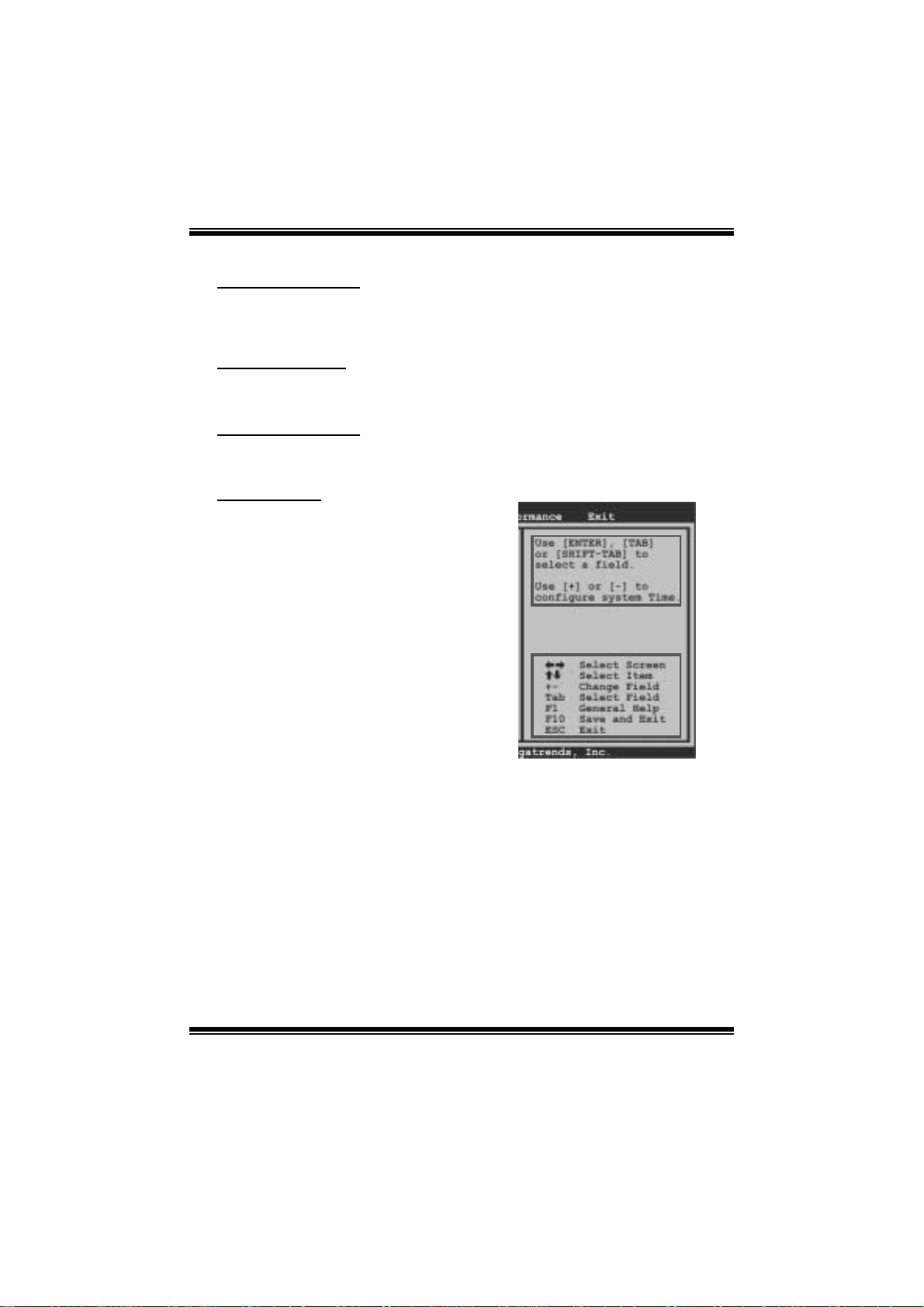
Using Setup
When starting up the computer, press
<Del> during the Power-On Self-Test
(POST) to enter the BIOS setup utility.
In the BIOS setup utility, you will see
General Help description at the top right
corner, and this is providing a brief
description of the selected item.
Navigation Keys for that particular menu
are at the bottom right corner, and you can
us e these keys to select item and ch ange
the settings.
Notice
z T he default B IOS settings apply for most conditions to ensure optimum performance
of the motherboard. If the system becomes unstable after changing any settings,
please load the default settings to ensure system’s compatibility and stability. Use
Load S etup Default under the Exi t Menu.
z For better system per form ance, the BIOS firmwa re is being continuously updated.
T he BIOS information described in this manual is for your reference onl y. The actual
BIOS i nformat ion and settings on board may be slightly differ ent from this manual.
z T he content of this manual is subject to be changed without notice. We will not be
responsible for any m istakes found in this user’ s manual and any system damage that
may be caused by wrong-settings.
General Help
Navigati on Keys
2
Page 4

G41D3 BIOS Manual
1 M ain Men u
Once you enter AMI BIOS Setup Utility, the Main Menu will appear on the screen
providing an overview of the basi c system inform ation.
Main Advanced PCIPnP Boot Chipset Performance
System Overview
AMI BIOS
Version :01.01.01
Build Date:01/01/09
System Memory
Size :
System Time 00
System Date [Thu 01/01/2009]
Floppy A
> IDE Configuration
vxx.xx (C)Copyright 1985-200x, American Megatrends, Inc.
AM I BIO S
Shows s ystem information including B IOS version, built date, etc.
BIOS SETUP UTILITY
[ :00:00]
Exit
Use [ENTER], [TA B]
or [SHIFT-TAB] to
select a field.
Use [+] or [-] to
configure system Time.
Select Screen
Select Item
Change Field
+-
Select Field
Tab
General Help
F1
Save and Exit
F10
Exit
ESC
System Memory
Shows s ystem memory size, VGA shard mem ory will be excluded. .
System Time
Set the system internal clock.
System Date
Set the system date. Note that the ‘Day’ automatically changes when you set the
date.
3
Page 5

G41D3 BIOS Manual
Floppy A
Select the type of floppy disk drive inst alled in your system.
Options: 360K, 5. 25 in / 1.2M, 5. 25 in / 720K, 3.5 i n / 1.44M, 3. 5 in /
2.88M, 3.5 in / None
IDE Configuration
Th e BIOS wi ll au t o m at ical l y detect t h e presen c e o f ID E / SAT A d evices . Th ere i s a
su b-menu fo r each IDE/ SAT A dev ice. Select a device and press <Ent er> to enter
the sub-menu of detailed opti ons.
Main
IDE Confuguration
ATA/IDE Configuration [Enhanced]
Configure SATA Channels [Before PATA]
Legacy IDE Channels [SATA Pri, PATA Sec]
> SATA1 Device
>
SATA2 Device
> SATA3 Device
> SATA4 Device
> IDE Channel 1 Master
> IDE Channel 1 Slave
Hard Disk Write Protect [Disabled]
IDE Detect Time Out (Sec) [35]
BIOS SETUP UTILITY
Options
Disabled
Compatible
Enhanced
Select Screen
Select Item
Go to Sub Screen
Enter
General Help
F1
Save and Exit
F10
Exit
ESC
vxx.xx (C)Copyright 1985-200x, American Megatrends, Inc.
ATA/IDE Confi guration
T his i tem allows you to control the onboard IDE controller.
Options: Enhanced (Default) / Compatible / Disabled
Confi gur e SATA Cha nnels
T his i tem allows you to control the S ATA channel configuration sequenc e.
Options: Befo re PATA (De fault) / Behind PAT A
Legac y IDE Channels
T his item appears only when “ATA/IDE C onfiguration” is set to “Compatible”.
Options: SATA Pri, PATA Sec (Default) / SATA Only / PATA Pri, SATA Sec /
PAT A Only
4
Page 6

G41D3 BIOS Manual
SATA1/2/3/4 Device; IDE Channel 1 Master/Slave
Main
SATA1 Device
Device :
Type [Aut o]
LBA/Large Mode [Aut o]
Block (Multi-S e ctor Transfer)[Aut o]
PIO Mode [Aut o]
DMA Mode [Aut o]
S.M.A.R.T [Aut o]
32Bit Data Tra n sfer [Ena bled]
vxx . xx (C)Copyright 1985-200x, American Megatrends, Inc.
BIOS SETU P UTILITY
Select the type
of device connected
to the system.
Select Screen
Select Item
Change Option
+-
General Help
F1
Save and Exit
F10
Exit
ESC
The BIOS detects the information and values of respective devices, and these
information and values are shown below to the nam e of the sub-menu.
Type
Select the type of the IDE/SATA drive.
Opti ons: Aut o (De faul t) / C D/DVD / AR M D / No t In st all ed
LBA/Large Mode
Enable or disabl e the LBA m ode.
Options: Auto (Default) / Disabled
Block (Multi-S ector Transfer)
En able o r d i s ab l e m u l ti -s ect o r t ran s fer .
Options: Auto (Default) / Disabled
PIO Mode
Select the P IO mode.
Options: Auto (Default) / 0 / 1 / 2 / 3 / 4
DMA Mode
Select the DMA mode.
Options: Auto (Default) / Disabled
5
Page 7

G41D3 BIOS Manual
S.M.A.R.T
Set the Smart Monitoring, Analysis, and R eport ing Technology.
Options: Auto (Default) / Disabled / Enabled
32Bit Data Tran sfer
Enable or disabl e 32-bit data transfer.
Options: Enabled (Default) / Disabled
Har d Disk Wri te Protec t
Disable or enable device write protection. This will be effective only if the device
is accessed through B IOS.
Options: Disabled (De fault) / Enabled
IDE Detect Time Out (Sec)
Select the time out val ue for detecting IDE/S AT A devices.
Options: 35 (Default) / 30 / 25 / 20 / 15 / 10 / 5 / 0
6
Page 8
G41D3 BIOS Manual
2 Advanced Menu
T he Advanced Menu allows you to configure the settings of C P U, Super I/O, P ower
Management, and other syst em devices.
Notice
z Beware of that setting inappropriate values in items of this menu may cause
system to m alfuncti on.
Main Advan ced PCIPnP Boot Chipset Performance
WARNING: Setti n g wrong values in below sections
may c a use system to malf unction.
> CPU Configur a tion
> SuperIO Conf i guration
> Hardware Hea l th Configuration
> Smart Fan Co n figuration
> Power Config u ration
> USB Configur a tion
BIOS SETU P UTILITY
Configure CPU.Advanced Setti n gs
Exit
Select Screen
Select Item
Go to Sub Screen
Enter
General Help
F1
Save and Exit
F10
Exit
ESC
vxx . xx (C)Copyright 1985-200x, American Megatrends, Inc.
CPU Configuration
T his item shows the CPU information that the B IOS automatically detects.
Advanced
Configure advanced CPU settings
Module Version:xx.xx
Manufacturer:Intel
Frequency :
FSB Speed :
Cache L1 :
Cache L2 :
Ratio Actual Value:
Hardware Prefetcher [Enabled]
Adjacent Cache Line Prefetch [Enabled]
Max CPUID Value Limit [Disabled]
Intel(R) Virtualization Tech [Enabled]
Execute-Disable Bit Capability[Enabled]
PECI [Enabled]
Core Multi-Processing [Enabled]
vxx.xx (C)Copyright 1985-200x, American Megatrends, Inc.
BIOS SETUP UTILITY
7
For UP platforms ,
leave it enabled.
For DP/MP server s,
it may use to tune
performance to the
specific application.
Select Screen
Select Item
Change Option
+F1
General Help
F10
Save and Exit
ESC
Exit
Page 9

G41D3 BIOS Manual
Hardware Prefetcher
Th e proces s or has a h ardware p refet ch er t h at au t omat ical l y anal yzes it s requ irem en t s
and pre fet ch es dat a and in s t ru ct ion s fro m t h e m emory i n t o the L ev el 2 cach e t h at are
likely to be required in the near future. This reduces the latency associated with
m emory read s.
Options: Enabled (Default) / Disabled
Adj acent Cache Line Prefetch
The processor has a hardw are adjacent cache line prefet ch mech anism that
aut o mat i cal l y fet ch es an ext ra 6 4-by t e cach e l i ne when ever t h e p ro ces s o r request s for
a 64-byte cache line. This reduces cache latency by making the next cache line
immediately available if the processor requires it as well.
Options: Enabled (Default) / Disabled
M ax CPUI D Va l ue Limit
When the computer is booted up, the operating system executes the CPUID
instruction to identify the processor and its capabilities. Befo re it can do so, it must
first query the processor to find out the highest input value CPUID recognizes. T his
determines t he ki nd of basic information C P UID can provi de the operat ing system .
Options: Disabled (De fault) / Enabled
Inte l(R) Virtualiza tion Te c h
Virtualization Technology can virtually separate your system resou rce into several
parts, thus enhance the performance when running virtual machines or multi
interfa ce systems.
Options: Enabled (Default) / Disabled
Execute-Disable Bit Capability
T his i tem allows you to configure th e Execute Disabled Bit function, which protects
your s ystem from buffer over flow attacks.
Options: Enabled (Default) / Disabled
PECI
T his item allows you to control the PECI function for the processor which supports
Platform Environm ent Control Interface for bet ter therm al m anagement.
Options: Enabled (Default) / Disabled
8
Page 10

G41D3 BIOS Manual
Core Multi-Processing
T his item allows multi-processing fun ction for multi-cor e processors.
Options: Enabled (Default) / Disabled
S uperI O Co n f i g urat i o n
Advanced
Configure ITE8718 Super IO Chipset
Onboard Floppy Controller [Enabled]
Serial Port1 Address [3F8/IRQ4]
Parallel Port Address [378]
Parallel Port Mode [Normal]
Parallel Port IRQ [IRQ7]
Keyboard PowerOn [Disabled]
Mouse PowerOn [Disabled]
Restore on AC Power Loss [Power Off]
BIOS SETUP UTILITY
Allows BIOS to Enable
or Disable Floppy
Controller
Select Screen
Select Item
Change Option
+-
General Help
F1
Save and Exit
F10
Exit
ESC
vxx.xx (C)Copyright 1985-200x, American Megatrends, Inc.
Onboard Floppy Controller
Select enabled if your system has a floppy disk controller (FDC) installed on the
system board and you wish to use i t. If you installed anot her FDC or the system uses
no fl oppy drive, select di sabled in t his field.
Options: Enabled (Default) / Disabled
Serial Port1 Address
Select an address and corr esponding interrupt for the first and second seri al ports.
Options: 3F8/IR Q4 (Default) / 2F 8/IRQ3 / 3E8/IRQ4 / 2E8/ IRQ3 / Auto / Disabled
Parallel Port Address
Th i s i t em al l ows yo u to det ermine acces s onboard paral lel port controller with which
I/O Address.
Options: 378 (Default) / 278 / 3BC / Disabled
9
Page 11

G41D3 BIOS Manual
Parallel Port Mode
T his i tem allows you to determine how the parallel port should function.
Options: Normal (Default) Using Parallel port as Standard P rinter Port.
EPP Using Parallel P ort as Enhanced Parallel Port.
ECP Using Parallel port as Extended Capabilities Port.
ECP + EPP Using P arallel port as ECP & EPP mode.
ECP Mode DMA Channel
T his i tem allows you to s elect parallel port ECP DMA.
Opti ons: DMA3 (Default ) / DMA0 / DMA1
Parallel P ort IRQ
T his i tem allows you to s elect the IRQ for the onboard parallel port.
Options: IRQ7 (De fault) / IR Q5 / Disabled
Keyboard PowerOn
T his i tem allows you to control the keyboard power on function.
Options: Disabled (Default) / Specific Key / Stroke Key / Any Key
Specific Key Enter
T his i tem will show only when Keyboard PowerOn is set “Speci fic Key.”
Stroke Keys Selected
T his i tem will show only when Keyboard PowerOn is set “Stroke Key.”
Options: Ctrl+ F1 (Default) / Wake Key / Power Key / Ctrl+F2 / Ctrl+F3 /
C t rl +F 4 / Ct rl + F5 / Ct rl +F 6
Mouse PowerOn
T his i tem allows you to control the m ouse power on function.
Options: Disabled (De fault) / Enabled
10
Page 12

G41D3 BIOS Manual
Restor e on AC Powe r Loss
T his setting s pecifies how your system should behave a fte r a power fail or interrupt s
occurs. By choosing Disabled will leave the computer in the power off state.
Choosing Enabled will restore the system to the status before power failure or
interrupt occurs.
Options: Power O ff (Default) / P ower ON / Last S tate
Hardware Health Configuration
T his i tem shows the syst em temperature, fan speed, and volt age i nformation.
Advanced
Hardware Health Configuration
H/W Health Function [Enabled]
Shutdown Temperature Function[Disabled]
CPU Temperature
SYS Temperature
CPU Fan
System1 Fan
CPU Voltage
Chipset Voltage
+3.30V
+5.00V
+12.0V
FSB Voltage
Memory Voltage
5V(SB)
vxx.xx (C)Copyright 1985-200x, American Megatrends, Inc.
H/W Health Functio n
If with a monitoring system, the system will show PC healt h status during POST stage.
Options: Enabled (Default) / Disabled
Shutdown Tem perature Function
T his item allows you to set up the CP U shutdown T emperature. This item is only
effecti ve under Wi ndows 98 ACPI m ode.
Options: Disabled (De fault) / 60℃/140℉ / 65℃/149℉ / 7 0℃/158℉ / 75 ℃/167℉
/ 80℃/176℉ / 85 ℃/185℉ / 90℃/194℉
BIOS SETUP UTILITY
Enables Hardware
Health Monitoring
Device.
Select Screen
Select Item
Change Option
+-
General Help
F1
Save and Exit
F10
Exit
ESC
11
Page 13

G41D3 BIOS Manual
Smart Fan Confi guration
Advan ced
Smart Fan Conf iguration
CPU Smart Fan [Disabled]
Smart Fan Cali bration
Control Mode
Fan Ctrl OFF( C)
Fan Ctrl On(C)
Fan Ctrl Start value
Fan Ctrl Sensi tive
o
o
BIOS SETU P U TILITY
When you choice [Auto]
, please run the
calibration to define
the Fan parameters for
Smart Fan control
Select Screen
Select Item
Change Option
+-
General Help
F1
Save and Exit
F10
Exit
ESC
vxx .xx (C)Copyright 1985-200x, American Me gatrends, Inc.
CPU Sma r t Fa n
This item a llo w s you to control the CPU Smart Fan function.
Options: Disabled (De fault) / Auto
Sm art Fan Ca l i bration
Choose this item and then the BIOS will auto test and detect the CPU/System fan
functi ons and show CPU/Syst em fan speed.
Contr ol Mode
T his item provides several operation modes of the fan.
Options: Quiet / Performance / Manual
Fan Ctrl OFF (℃)
If the CP U/System T emperature is lower than the set value, F AN will turn off.
Options: 0~127 (℃) (Interval: 1℃)
Fan Ctrl On(℃ )
CPU/S ystem fan starts to work under smart fan function when arrive this set value.
Options: 0~127 (℃) (Interval: 1℃)
12
Page 14

G41D3 BIOS Manual
Fan Ctrl Start Value
When CPU/System temperature arriv es to the set value, the CPU/System fan will
work under Smart Fan F unction mode.
Options: 0~127 (Interv al: 1)
Fan Ctrl Sensiti ve
Increasi ng t h e valu e w ill rai s e t he sp eed of C P U / Sy s t em fan.
Options: 1~127 (Interv al: 1)
Power Con figuration
Advanced
ACPI Settings
Suspend mode [S1(POS)]
Repost Video on S3 Resume [NO]
ACPI Version Features [ACPI v1.0]
ACPI APIC support [Enabled]
AMI OEMB table [Enabled]
Headless mode [Disabled]
APIC ACPI SCI IRQ [Disabled]
USB Device Wakeup From S3/S4 [Disabled]
High Performance Event Timer [Disabled]
Advanced Resume Event Controls
Resume On Ring [Disabled]
Resume On PME# [Disabled]
Resume On RTC Alarm [Disabled]
BIOS SETUP UTILITY
Select the ACPI
state used for
System Suspend.
Select Screen
Select Item
Change Option
+-
General Help
F1
Save and Exit
F10
Exit
ESC
vxx.xx (C)Copyright 1985-200x, American Megatrends, Inc.
Suspe nd m ode
T he item allows you to select the suspend type under t he AC P I operating syst em.
Opt i ons : S 1 (PO S ) (Defau l t ) Power on Suspen d
S3 (STR) Suspend to RAM
Auto POS+STR
Repost Video on S3 Re sume
T he item allows you to determine whether to invoke VGA BIOS post on S3/ST R
resume .
Options: No (Default) / Yes
13
Page 15

G41D3 BIOS Manual
ACPI Version Features
Th e item al l o ws yo u to sel ect t he vers i o n of ACPI.
Options: ACP I v1.0 (Default) / ACP I v2. 0 / ACPI v3. 0
ACPI AP I C support
This item is used to enable or disable the motherboard's APIC (Advanced
Programmable Interrupt Controller). The APIC provides multiprocessor support,
more IRQs and faster interrupt handling.
Options: Enabled (Default) / Disabled
AMI OEMB table
Set this value to allow the ACPI BIOS to add a pointer to an OEMB table in the Root
Syst em Description Table (RSDT ) table.
Options: Enabled (Default) / Disabled
Headless mode
This is a server-specific feature. A headless server is one that operates without a
keyboard, monitor or mouse. To run in headless mode, both BIOS and operating
system (e.g. Windows S erver 2003) must support headless operati on.
Options: Disabled (De fault) / Enabled
APIC ACPI SCI IRQ
Options: Disabled (De fault) / Enabled
USB Device Wakeup from S3/S4
T his i tem allows you to enable or disabled the USB resume from S3/S4 function.
Options: Disabled (De fault) / Enabled
High P erformance Ev ent Timer
T his i tem allows you to enable or disabled the HPET.
Options: Disabled (De fault) / Enabled
14
Page 16

G41D3 BIOS Manual
HPET Memory Address
T his i tem allows you to s et the memory address of HP ET .
Options: FED00000h (De fault) / FED01000h / FED02000h / FED03000h
Resume On R in g
T his i tem allows you to control the wake on ring function.
Options: Disabled (De fault) / Enabled
Resume On P ME#
W hen you s elect Enabled, a PME signal from P CI card returns the syst em to Ful l ON
state. For this function to work, you may need a LAN add-on card which supports
the Wake on LAN function. Set the Wake on LAN (WOL) jumper on motherboard
to enabl e i f app l i cab l e.
Options: Disabled (De fault) / Enabled
Resum e O n RTC Alarm
When “ Enabled”, you can set the date and time at which the RT C (real-time clock)
alar m awaken s th e s y s tem fro m Su s p en d mo d e.
Options: Disabled (De fault) / Enabled
RTC Alar m Date (Days )
You can choose which date the syst em will boot up.
RTC Al arm Ti me
You can choose the system boot up time, input hour, minute and second t o specify.
15
Page 17

G41D3 BIOS Manual
USB Configuration
T his i tem shows the USB controller and usi ng USB device information.
Advanced
USB Configuration
Module Version - 2.24.3-13.4
USB Devices Enabled:
Legacy USB Support [Enabled]
USB 2.0 Controller Mode [HiSpeed]
BIOS EHCI Hand-Off [Enabled]
> USB Mass Storage Device Configuration
BIOS SETUP UTILITY
Options
Disabled
Enabled
Auto
Select Screen
Select Item
Change Option
+-
General Help
F1
Save and Exit
F10
Exit
ESC
vxx.xx (C)Copyright 1985-200x, American Megatrends, Inc.
Legacy USB Support
T his item determines if the BIOS should provide legacy support fo r US B devices
li ke the key board, mo use, and US B d rive. This is a useful fe atu re when u si ng such
USB devices with operating systems that do not natively support USB (e.g.
Microsoft DOS or Windows NT).
Options: Enabled (Default) / Disabled / Auto
USB 2.0 Controller Mode
T his i tem allows you to s elect the operation mode of the USB 2.0 cont roller.
Options: HiSpeed (De fault) USB 2.0-480Mbps
FullSpeed USB 1.1-12Mbps
BIO S EHCI Hand-Off
This item allows you to enable support for operating systems without an EHCI
hand-o ff feature.
Options: Enabled (Default) / Disabled
16
Page 18

G41D3 BIOS Manual
US B Mass Sto rag e De vice Co nfigurat io n
Advanced
USB Mass Storage Device Configuration
USB Mass Storage Reset Delay [20 Sec]
Device #
Emulation Type [Auto]
vxx.xx (C)Copyright 1985-200x, American Megatrends, Inc.
BIOS SETUP UTILITY
Number of seconds
POST waits for the
USB mass storage
device after start
unit command.
Select Screen
Select Item
Change Option
+-
General Help
F1
Save and Exit
F10
Exit
ESC
USB Mass Storage Reset Delay
T his i tem allows you to s et the reset del ay for USB mass storage device.
Op t i ons : 20 Sec (D e faul t ) / 1 0 S ec / 3 0 S ec / 40 S ec
E m ula ti on T ype
T his i tem allows you to s elect the emulation type of the USB m ass storage device.
Options: Auto (Default) / Floppy / Forced FDD / Hard Disk / CDROM
17
Page 19

G41D3 BIOS Manual
3 PCIPnP Menu
T his section describes con figuring the PCI bus system. PCI, or Personal Computer
Interconnect, is a system which allows I/O devices to operate at speeds nearing the
speed of the CP U itself uses when communicating with its own special components.
Notice
z Beware of that setting inappropriate values in items of this menu may cause
system to m alfuncti on.
Main Advanced PCIPnP Boot Chips et Performance
Advanced PCI/PnP Settings
WARNING: Setting wrong values in below sections
may cause system to malfunction.
Clear NVRAM [No]
Plug & Play O/S [No]
PCI Latency Timer [64]
Allocate IRQ to PCI VGA [Yes]
Palette Snooping [Disabled]
PCI IDE BusMaster [Enabled]
> PCI Resource
BIOS SETUP UTILITY
Exit
Clear NVRAM during
System Boot.
Select Screen
Select Item
+-
Change Option
F1
General Help
Save and Exit
F10
Exit
ESC
vxx.xx (C)Copyright 1985-200x, American Megatrends, Inc.
Clear NVRAM
T his i tem allows you to clear the data in the NVRAM (CMOS) by selecting “ Yes”.
Options: No (Default) / Yes
Plug & Play OS
When set to YES, BIOS will only initialize the PnP cards used for the boot sequen ce
(VGA, IDE, SCSI). The rest of the cards will be initialized by the PnP operating
system like Window™ 95. W hen set to NO, BIOS will initialize all the PnP cards.
For non-PnP operating systems (DOS, Netware™), this option must set to NO.
Options: No (Default) / Yes
18
Page 20

G41D3 BIOS Manual
PCI Latency Tim er
T his i tem controls how long a PC I device can hold t he PCI bus be for e anot he r takes
over. T he longer the latency, the longer the PC I device can retain control of the bus
before handing it over to another PCI devi ce.
Options: 64 (Default) / 32 / 96 / 128 / 160 / 192 / 224 / 248
Allocate IRQ to PCI VGA
T his i tem allows B IOS to choose a IRQ to assign for the PCI VGA card.
Opti ons: Yes (De fault ) / No
Palette Snooping
Som e old graphic controllers need to “snoop” on the VGA palette and then map it t o
their dis play as a way to provide boot information and VGA compati bility. This item
allows such snooping to take place.
Options: Disabled (De fault) / Enabled
PCI IDE BusMaster
T his i tem is a toggle for the built-in driver that allows t he onbo ard ID E controller to
perform D M A (Di r ect Mem o ry Acces s ) tran s fers .
Options: Enabled (Default) / Disabled
PCI Resource
PCIPnP
PCI Resource
IRQ3 [Available]
IRQ4 [Available]
IRQ5 [Available]
IRQ7 [Available]
IRQ9 [Available]
IRQ10 [Available]
IRQ11 [Available]
IRQ14 [Available]
IRQ15 [Available]
DMA Channel 0 [Available]
DMA Channel 1 [Available]
DMA Channel 3 [Available]
DMA Channel 5 [Available]
DMA Channel 6 [Available]
DMA Channel 7 [Available]
Reserved Memory Size [Disabled]
vxx.xx (C)Copyright 1985-200x, American Megatrends, Inc.
BIOS SETUP UTILITY
19
Available: Specified
IRQ is available to be
used by PCI/PnP
devices.
Reserved: Specified
IRQ is reserved for
use by Legacy ISA
devices.
Select Screen
Select Item
+-
Change Option
F1
General Help
F10
Save and Exit
ESC
Exit
Page 21

G41D3 BIOS Manual
IRQ3/4/5/7/9/10/11/14/15
T hese items will allow you to assign each system interrupt a type, depending on the
type of device using the interrupt. The option “Available” means the IRQ is going
to assign automatically.
Options: Available (De fault) / Reserved
DMA Channel 0/1/3/5/6/7
T hese items will allow you to assign each DMA channel a type, depending on the
type of device using the channel. The option “ Available” means the channel is
going to assign automatically.
Options: Available (De fault) / Reserved
Reser ved M emo ry Size
T his item allows BIOS to reserve certain memory size for speci fic PCI device.
Options: Disabled (Default) / 16K / 32K / 64K
20
Page 22

G41D3 BIOS Manual
4 Boot Menu
T his m enu allows you to set up the syst em boot opti ons.
Main Advan ced PCIPnP Boot Chipset Performance
Boot Settings
> Boot Device Priority
> Hard Disk Dr ives
> Removable Dr ives
> CD/DVD Drive s
> Boot Setting s Configuration
BIOS SETU P U TILITY
Exit
Specifies the
Boot Device
Priority sequence.
Select Screen
Select Item
Enter
Go to Sub Screen
F1
General Help
F10
Save and Exit
ESC
Exit
vxx .xx (C)Copyright 1985-200x, American Me gatrends, Inc.
Boot Device Prio rity
Item s in this sub-menu specify the boot device priority sequence from the available
devices. The number of device items that appears on the screen depends on the
number of devices install ed in the system.
Hard Disk Drives
T he BIOS w ill attempt t o arrange th e hard disk bo ot sequence automat ically. You
can also ch ange t he b o oti n g s equence. T h e n u mber o f device it ems t h at ap p ears on
the screen depends on the number of devices installed in the system.
Re mo va ble Dr ives
T he BIOS w ill attempt t o arrange t he removable dri ve bo ot sequence automati cally.
You can also change the booting sequence. The number of device items that
appears on the screen depends on the number of devic es installed in the syst em.
21
Page 23

G41D3 BIOS Manual
CD/DVD Drives
T he BIOS will attempt to arrange the CD/DVD drive boot sequence automatically.
You can also change the booting sequence. The number of device items that
appears on the screen depends on the number of devic es installed in the syst em.
Boot Settings Configuration
BIOS SETUP UTILITY
Boot
Boot Settings Conf iguration
Quick Boot [Enabled]
Full Screen LOGO Show [Enabled]
AddOn ROM Display Mode [Force BIOS]
Bootup Num-Lock [ON]
Interrupt 19 Capture [Disabled]
BOOT SUCCESS BEEP [Enabled]
Allows BIOS to skip
certain tests while
booting. This will
decrease the time
needed to boot the
system.
Select Screen
Select Item
Change Option
+F1
General Help
Save and Exit
F10
Exit
ESC
vxx.xx (C)Copyright 1985-200x, American Megatrends, Inc.
Quick Boot
Enabling this option will cause an abridged version of the Power On Self-Test
(POST) to execute after you power up the computer.
Options: Enabled (Default) / Disabled
Full Screen LOGO S ho w
T his i tem allows you to enable/di sable Full Screen LOGO Show f unction.
Options: Enabled (Default) / Disabled
AddOn RO M Display Mode
T his item sets the display mode for option ROM.
Op t i ons : F orce B IOS (D efault) / Keep Cu rren t
22
Page 24

G41D3 BIOS Manual
Bootup Num-Lock
Selects the NumLock State after the system switched on.
Options: ON (Default) / OF F
Interrupt 19 Capture
Interrupt 19 is the software int errupt that handles the boot disk function. W hen set to
Enabled, this item allows the option ROMs to trap interrupt 19.
Options: Disabled (De fault) / Enabled
BOOT SUCCESS BEEP
W hen t his item is set to Enabled, BIOS will let user know boot success with beep.
Options: Enabled (Default) / Disabled
23
Page 25

G41D3 BIOS Manual
5 Chipset Menu
Th i s su b m en u all o w s you to co nfi g ur e t he speci fic feat u res of the chi ps et i n s tal l ed o n
your system. This chipset manage bus speeds and access to system memory
resourc es, such as DRAM. It al so coordinates communications with the P C I bus.
Notice
z Beware of that setting inappropriate values in items of this menu may cause
system to m alfuncti on.
Main Advan ced PCIPnP Boot Chipset Performance
Advanced Chips et Settings
WARNING: Setti ng wrong values in below sections
may c ause system to malfunction.
> North Bridge Configuration
> South Bridge Configuration
BIOS SETU P U TILITY
Configure North Bridge
features
Exit
Select Screen
Select Item
Go to Sub Screen
Enter
General Help
F1
Save and Exit
F10
Exit
ESC
vxx .xx (C)Copyright 1985-200x, American Me gatrends, Inc.
24
Page 26

G41D3 BIOS Manual
Nort h Bridge C onf i gur ation
BIOS SETUP UTILITY
North Bridge Chipset Configuration
Memory Remap Feature [Enabled]
PCI MMIO Allocation:
Memory Hole [Disabled]
Initiate Graphic Adapter [PEG/PCI]
IGD Graphics Mode Select [Enabled, 32MB]
IGD GTT Graphics memory size [No VT mode, 2MB]
PEG Port Configuration
PEG Port [Auto]
> Video Function Configuration
vxx.xx (C)Copyright 1985-200x, American Megatrends, Inc.
Chipset
ENABLE: Allow
remapping of
overlapped PCI memory
above the total
physical memory.
DISABLE: Do not allow
remapping of memory.
Select Screen
Select Item
Change Option
+F1
General Help
Save and Exit
F10
Exit
ESC
M emory Re map Featur e
This item allows you to enable or disable the remapping of the overlapped PCI
memory above the total physical memory. Only 64-bit OS supports this function.
Options: Enabled (Default) / Disabled
Memory Hole
You can reserve this area of system memory for IS A adapter R OM. W hen t hi s area
is reserved it cannot be cached . C heck th e user informat ion of periphe rals that need
to u se thi s area o f s y st em m em ory fo r t he mem ory requi rement s .
Options: Disabled (Default) / 15MB – 16M B
Initiate G ra phic Adapter
T his i tem allows you to enable or disable VGA controller.
Opti ons: PEG/PC I (Default ) / IGD / P CI/IGD / PC I/P E G / P EG/ IGD
IGD Graphic s Mode Sel ect
This item will be different as your memory modules. When the memory size is
decided, this fram e buffer size will also be fixed.
Options: Enabled,32MB (Defaul t) / Enabled,64MB / Enabled,128MB / Disabled
25
Page 27

G41D3 BIOS Manual
PEG Port
T his B IOS feature is a toggl e that enables or disabl es the PCI Express port.
Options: Auto (Default) / Disabled
Vi deo Functi on Configuration
BIOS SETUP UTILITY
Video Function Configuration
DVMT Mode Select [DVMT Mode]
DVMT/FIXED Memory [256MB]
PAVP Mode [Disabled]
Spread Spectrum Clock [Disabled]
Chipset
Options
DVMT Mode
Select Screen
Select Item
Change Option
+-
General Help
F1
Save and Exit
F10
ESC
Exit
vxx.xx (C)Copyright 1985-200x, American Megatrends, Inc.
DVMT Mode Select
T his i tem allows you to s elect the DVMT m ode.
Options: DVMT Mode (Default)
DVMT/F IXED Memory
DVMT stands for “ Dynamic Video Memory T echnology”. T his is an enhancement
of the unified memory architecture (UMA) concept. DVMT will set the optimum
amount of memory to be allocated for a balance between graphics and system
perform anc e. DVMT dynamically respond to system requirements and applications
demands, by allocating the proper amount of display, texturing and buffer memory
after the oper ati ng system has boot ed.
Options: 256MB (Default) / 128MB / Maximum DVMT
PAVP Mode
GMCH P rotected Audio Video Path (PAVP ) BIOS support.
Options: Disabled (De fault) / Lite / High
Spread Spectrum Clock
T his i tem allows you to control the spread spectrum clock.
Options: Disabled (De fault) / Enabled
26
Page 28

G41D3 BIOS Manual
South Br idge C onfigura tion
BIOS SETU P U TILITY
South Bridge C hipset Configuration
USB Functions [8 USB Ports]
USB 2.0 Contro ller [Enabled]
Audio Controll er [Azalia]
Onboard Lan Co ntrol [Enabled]
Onboard Lan Bo ot ROM [Disabled]
MAC ID Informa tion
SMBUS Controll er [Enabled]
SLP_S4# Min. A ssertion Width [1 to 2 seconds]
vxx .xx (C)Copyright 1985-200x, American Me gatrends, Inc.
Chipset
Options
Disabled
2 USB Ports
4 USB Ports
6 USB Ports
8 USB Ports
Select Screen
Select Item
Change Option
+-
General Help
F1
Save and Exit
F10
Exit
ESC
USB Functions
T he item determ ines the number of functional USB port.
Options: 8 USB Ports (Default) / 6 USB Ports / 4 USB Ports / 2 USB Ports /
Disabled
USB 2.0 Controller
T his entry is to enabled/ disabled EHCI controller onl y. This Bios its elf m ay/may not
have high speed USB support. If the BIOS has high s peed US B support buil t in, the
support will be automatically turn on when high speed device were attached.
Options: Enabled (Default) / Disabled
Audio Control ler
T his i tem allows you to s elect the Audio support.
Options: Azalia (Default) / All Disabled
Onboard Lan Control
T his i tem allows you to enable or disable the Onboard LAN.
Options: Enabled (Default) / Disabled
27
Page 29

G41D3 BIOS Manual
Onboard Lan Boot Rom
T his i tem allows you to s elect the status of Onboard LAN Boot ROM.
Options: Disabled (De fault) / Enabled
MAC ID Informa tion
T his item shows the LAN MAC ID.
SMBUS Controller
T h is BIOS feat ure c o nt ro ls t he I/ O bu ff e rs fo r t he S M B u s.
Options: Enabled (Default) / Disabled
SLP_S4# Min. As serti on Width
Options: 1 to 2 seconds (Default) / 4 to 5 seconds / 3 to 4 seconds / 2 to 3 seconds
28
Page 30

G41D3 BIOS Manual
6 Performance Menu
T his subm enu allows you t o change voltage and clock of various devices.
(However, we suggest you use the default setting. Changing the voltage and clock
improperly may damage the devi ce. )
Notice
z Beware of that setting inappropriate values in items of this menu may cause
system to m alfuncti on.
Main Advanced PCIPnP Boot Chips et Performance
Advance Performance Settings
WARNING:Please Clea r CMOS if sys tem no displ ay
after overclocking.
PSI Control [Enabled]
CPU Frequency Setting
PCIE Clock By [Auto]
PCIE Frequency Setting [100]
CPU Voltage [Default]
MCH REF Voltage [Default]
FSB Voltage [Default]
Chipset Voltage [Default]
Memory Voltage [Default]
DRAM Frequency [Auto]
Configure DRAM Timing by SPD [Enabled]
[333]
BIOS SETUP UTILITY
PSI Control by superio
Exit
Select Screen
Select Item
Enter
Go to Sub Screen
F1
General Help
Save and Exit
F10
Exit
ESC
vxx.xx (C)Copyright 1985-200x, American Megatrends, Inc.
PSI Con tro l
This item allows you to control power supply of CPU for the purpose of saving
energy.
Options: Enabled (Default) / Disabled
CPU Frequency Setting
T his i tem allows you to s elect the CPU Frequency.
Options: 333 (Default) / Min= 100MHz; Max= 600MHz
PCIE Clock B y
T his i tem allows you to s elect the PCIE clock control
Options: Auto (Default) / Manual
29
Page 31

G41D3 BIOS Manual
PCIE Fre quenc y Se tt i ng
T his i tem allows you to s elect the PCIE clock control
Options: 100 (Default) / Min=100; Max= 150
CPU Voltage
T his i tem allows you to s elect CPU Voltage Control.
Options: Default (Default) / +5% / +10% / +15%
MCH REF V oltage
T his i tem allows you to s elect MCH REF Voltage C ontrol.
Options: Default (Defaul t) / 0.63*VTT / 0. 61*VTT / 0. 58*VTT
FS B Voltage
T his i tem allows you to s elect FSB Voltage Control.
Options: Default (Default) / +0.1V / +0.2V / +0.3V
Chipset Voltage
T his i tem allows you to s elect Chipset Voltage Control.
Options: Default (Default) / +0.1V / +0.2V / +0.3V
Memory Voltage
T his i tem allows you to s elect Mem ory Vol tage Control.
Options: Default (Default) / +0.05V / +0.10V / +0.15V / +0.20V / +0.25V /
+0.30V / +0. 35V
DRAM Fr eq uency
T his i tem allows you to control the Memory C lock.
Options: Auto (Default) / DDR3-800 / DDR3-1066
Configure DRAM Timin g by SPD
Options: Enabled (Default) / Disabled
DRAM tCL
Options: 3 (De fault) / 3 ~ 10
30
Page 32

G41D3 BIOS Manual
DRAM t RAS
Options: 9 (De fault) / 9 ~ 24
DRAM tRP
Options: 3 (De fault) / 3 ~ 10
DRAM t RCD
Options: 3 (De fault) / 3 ~ 10
DRAM tWR
Options: 3 (De fault) / 3 ~ 15
DRAM tRFC
Options: 15 (Default) / 15 ~ 78
DRAM tWTR
Options: 2 (De fault) / 2 ~ 15
DRAM t RRD
Options: 2 (De fault) / 2 ~ 15
DRAM tRTP
Options: 2 (De fault) / 2 ~ 15
31
Page 33

G41D3 BIOS Manual
7 Ex it Menu
This menu allows you to load the optimal default settings, and save or discard the
changes to the BIOS items.
Main Advan ced PCIPnP Boot Chipset Performance
Exit Options
Save Changes a nd Exit
Discard Change s and Exit
Discard Change s
Load Optimal D efaults
BIOS SETU P U TILITY
Exit
Exit system setup
after saving the
changes.
F10 key can be used
for this operation.
> Security
vxx .xx (C)Copyright 1985-200x, American Me gatrends, Inc.
Select Screen
Select Item
Go to Sub Screen
Enter
General Help
F1
Save and Exit
F10
Exit
ESC
Save Changes and Exit
Save all confi gur ation changes to CMOS R AM and exit setup.
Discard Changes and Exi t
Abandon all changes made during the current session and exit setup.
Discard Changes
Abandon all changes made during the current session and restore the previously
saved values.
Load Optimal Defaults
This selection allows you to reload the BIOS when problem occurs during system
booting sequence. These configurations are factory settings optimized for this
system .
32
Page 34

G41D3 BIOS Manual
Secur ity
T his sub-menu allows you to provide/revise supervisor and user password.
BIOS SETU P U TILITY
Exit
Security Setti ngs
Supervisor Pas sword :Not Installed
User Password :Not Installed
Change Supervi sor Password
User Access Le vel [Full Access]
Change User Pa ssword
Clear User Pas sword
Password Check [Setup]
Boot Sector Vi rus Protection [Disabled]
vxx .xx (C)Copyright 1985-200x, American Me gatrends, Inc.
Install or Change the
password.
Select Screen
Select Item
Enter
Change
F1
General Help
F10
Save and Exit
ESC
Exit
Change Superv i sor Pas swor d
Setting the supervisor password will prohibit everyone except the supervisor from
making changes using the CMOS Setup Utility. You will be prompted with to enter a
password.
User Acess Level
T his item allows supervisor to set the user level.
Op t i ons : F ull A cces s (De faul t) / N o A ccess / V iew On l y / L im i t ed
Cha nge Us er Password
If the Supervisor Password is not set, then the User Password will function in the
same way as the Supervisor Password. If the S upervisor Pas sword is set and the User
Password is set, the “ User” will only be able to view configurations but will not be
abl e to ch an g e t h em .
Cle ar Use r Passw ord
T his item is for clearing user passwo rd.
33
Page 35

G41D3 BIOS Manual
P asswo rd Check
T his item is for setting the timing that checking password.
Options: Setup (Default) / Always
Boot Sector Vi r us Protection
T his option allows you t o choose the VIR US W arning featur e that is used to protect
the IDE H ard Disk boot sector. I f this fun ction is enabled and an attempt is made to
write to the boot sector, BIOS will display a warning message on the screen and
sound an alarm beep.
Options: Disabled (De fault) / Enabled
34
 Loading...