

Page 1

A740G M2+ BIOS Manual
BIOS Setup ................................................................................................ 1
1 Main Menu ............................................................................................. 3
2 Advanced Menu...................................................................................... 6
3 PCIPnP Menu....................................................................................... 16
4 Boot Menu............................................................................................. 19
5 Chipset Menu ....................................................................................... 21
6 Performance Menu .............................................................................. 31
7 Exit Menu ............................................................................................. 33
i
Page 2

A740G M2+ BIOS Manual
BIOS Setup
Introduction
The purpose of this manual is to describe the settings in the AMI BIOS Setup
program on this motherboard. The Setup program allows users to modify the basic
system configuration and save these settings to CMOS RAM. The power of CMOS
RAM is supplied b y a battery so that it retains the Setup information when the po wer
is tu rned off.
Basic Input-Output System (BIOS) determines what a computer can do without
access ing programs from a disk. This system controls most of the input and output
devices such as ke ybo ard, mous e, ser ial ports and disk dr ives. BIOS ac tivates at the
first stage of the booting process, lo ading and executing the operating system. Some
additional features, such as virus and password protection or chipset fine-tuning
options are also inc luded in BIOS.
The rest of this manual will to guide yo u through the options and s ett ings in BIOS
Setup.
Plug and Play Support
This AMI BIOS supports the Plug and Play Version 1.0A specification.
EPA Green PC Support
This AMI BIOS supports Version 1.03 of the EPA Green PC specification.
APM Support
This AMI BIOS supports Vers ion 1.1&1.2 of th e Advanced Power Manage ment
(APM) specific ation. Po wer ma nagement features are impleme nted via the System
Management Interrupt (SMI). Sleep and Suspend power management modes are
supported. Power to the hard dis k drives and video monitors can also be managed by
this AMI BIOS.
ACPI Support
AMI ACPI BIOS support Version 1.0/2.0 of Advanced Configuration and Power
interface spec if ication (AC PI). It provides ASL code for power management and
device configuration capabilities as defined in the ACPI sp ecificat io n, developed by
Microsoft, Intel and Toshiba.
1
Page 3

A740G M2+ BIOS Manual
PCI Bus Support
This AMI BIOS also suppo rts Vers ion 2.3 of the Intel PCI (Peripheral Component
Interconnect) lo c a l b us s p ec ific a t ion.
DRAM Support
DDR2 SDRAM (Double Data Rate II Synchronous DRAM) is s upported.
Supported CPUs
This AMI BIOS supports the AMD CPU.
Using Setup
Whe n starting up t he co mp uter, press
<Del> during the Power-On Self-Test
(POST) to enter the BIOS setup utility.
In the BIOS setup utility, you will see
General Help description at the top right
corner, and this is providing a brief
descriptio n of the selected item.
Navigation Keys for that particular menu
are at the bottom right corner, and you c an
use these keys to select it em and c hange
the settings.
Notice
z The default BIOS settings apply for most conditions to ensure optimum performance
of the motherboard. If the system becomes unstable after changing any settings,
please load the default settings to ensure system’s co mpatibility and stability. Use
Load Setup Default under the Exit Menu.
z For better system perfo rmance, the BIOS firmware is being continuo usly updated.
The BIOS information described in this manual is for your reference only. The actual
BIOS information and settings on board may b e slightly different from this manual.
z The content of this manual is sub ject to b e changed without notice. We will not be
responsible for any mistakes found in this user’s manual and any system dama ge that
may b e caused by wrong-settings.
General Help
Navigation Keys
2
Page 4
A740G M2+ BIOS Manual
1 Main Menu
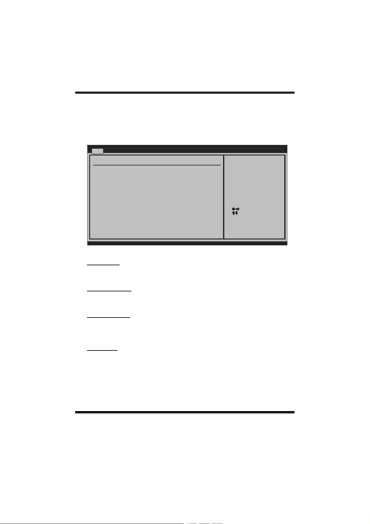
Once you enter AMI BIOS Setup Utility, the Main Menu will appear on the screen
providing an overview of the basic system information.
Main Advanced PCIPnP Boot Chi pset Performance
System Overview
AMI BIOS
Version :01.01.01
Build Date:01/01/08
System Time 00
System Date [Tue 01/01/2008]
Floppy A
> IDE Configuration
vxx.xx (C)Copyright 1985-200x, American Megatrends, Inc .
AMI BIOS
Shows system info rmation including BIOS version and built d ate.
BIOS SETUP UTILITY
[ :00:00]
Exit
Use [ENTER], [TAB]
or [SHIFT-TAB] to
select a field.
Use [+] or [-] to
configure system Time.
Select Screen
Select Item
+-
Change Field
Tab
Select Field
F1
General Help
F10
Save and Exit
ESC
Exit
System Time
Set t he sys tem internal c loc k.
System Date
Set the system date. Note that the ‘Day’ automatically changes when you set the
date.
Floppy A
Select the type of flopp y disk drive installed in yo ur s ystem.
Optio ns : 360K, 5.25 in / 1. 2M, 5.25 in / 720K, 3. 5 in / 1.44M, 3.5 in /
2.88M, 3.5 in / None
3
Page 5
A740G M2+ BIOS Manual
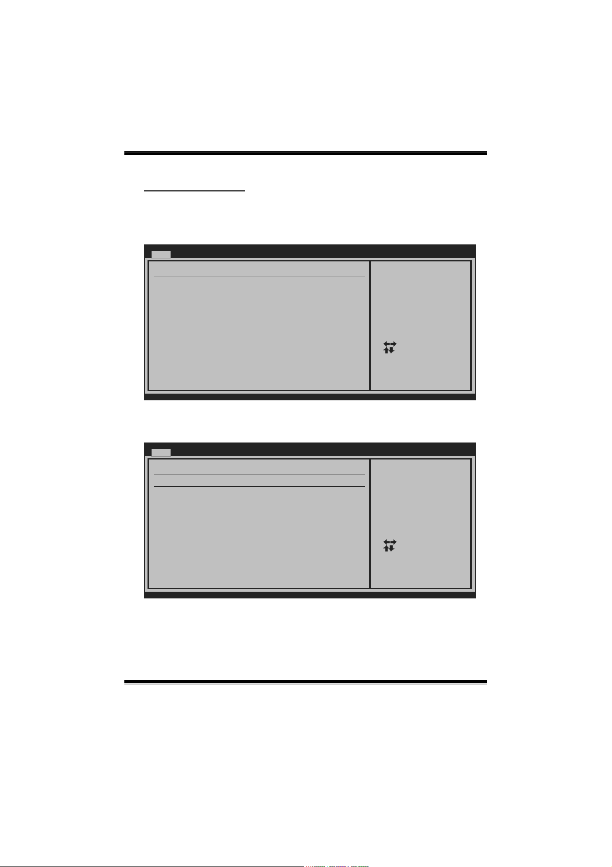
IDE Configuration
The BIOS will auto mat ically d etect the prese nce of I DE/ S ATA devices. There is a
sub-menu for each IDE/SATA device. Select a device and press <Enter> to enter
the sub-menu of detailed options.
Main
IDE Confuguration
> Primary IDE Master
> Primary IDE Slave
> SATA 1 Device
> SATA 2 Device
> SATA 3 Device
> SATA 4 Device
> SATA 5 Device
> SATA 6 Device
Hard Disk Write Protect [Disabled]
IDE Detect Time Out (Sec) [35]
BIOS SETUP UTILITY
While entering setup,
BIOS auto dete cts the
presence of ID E
devices. This displays
the status of auto
detection of IDE
devices.
Select Screen
Select Item
Go to Sub Screen
Enter
General Help
F1
Save and Exit
F10
Exit
ESC
vxx.xx (C)Copyright 1985-200x, American Megatrends, Inc.
Primary IDE Master/Slave ; SAT A 1/2/3/4/5/6 Device
Main
Primary IDE Master
Device :
Type [Auto]
LBA/Large Mode [Auto]
Block (Multi-Sector Transfer)[Auto]
PIO Mode [Auto]
DMA Mode [Auto]
S.M.A.R.T [Auto]
32Bit Data Transfer [Enabled]
vxx.xx (C)Copyright 1985-200x, American Megatrends, Inc.
BIOS SETUP UTILITY
Select the typ e
of device conn ected
to the system.
Select Screen
Select Item
Change Option
+-
General Help
F1
Save and Exit
F10
Exit
ESC
The BIOS detects t he information and values of respec tive devices, and these
info rmation and values are s hown below to the na me of the sub -menu.
4
Page 6

A740G M2+ BIOS Manual
Typ e
Select the type of the IDE/S ATA drive.
Optio ns: Auto (Default) / CDROM / ARMD / Not Installed
LBA/Large Mode
Enable or disable the LBA mode.
Optio ns: Auto (Default) / Disab led
Block (Multi-Sector Transfer)
Enable or disable multi-sec to r transfer.
Optio ns: Auto (Default) / Disab led
PIO Mode
Select the PI O mod e.
Optio ns: Auto (Default) / 0 / 1 / 2 / 3 / 4
DMA Mode
Select the DMA mode.
Optio ns: Auto (Default) / Disab led
S.M.A.R.T
Set the Smart Monitoring, Analysis, and Reporting Technology.
Optio ns: Auto (Default) / Disabled / Enabled
32Bit Data Tra nsfer
Enable or disable 32-bit data transfer.
Optio ns: Enabled (Default) / Disabled
Hard Disk Write Protect
Disab le or enable device write protection. This will be effective only if the device
is acc ess ed through BIOS.
Optio ns: Disabled (Default) / Enabled
IDE Detect Time Out (Sec)
Select the time out value for detecting IDE/SATA devic es.
Optio ns: 35 (Default) / 30 / 25 / 20 / 15 / 10 / 5 / 0
5
Page 7
A740G M2+ BIOS Manual
Y
Y
2 Advanced Menu
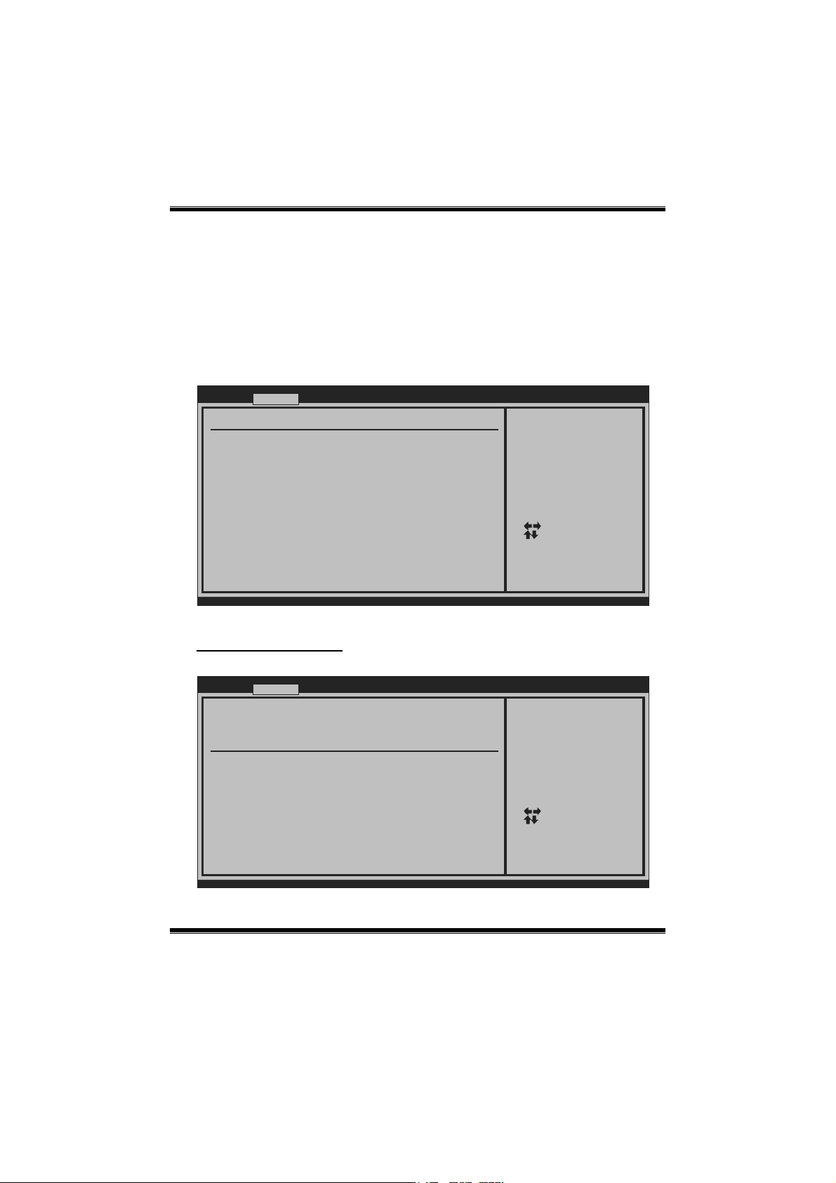
The Advanced Menu allows you to configure the settings of CPU, Super I/O, Power
Management, and other system devices.
Notice
z Beware of that s etting inappropriate values in items of this menu may cause
system to malfunction.
Main Advanced
WARNING: Setting wro ng values in below sections
may cause s ystem to malfunction.
> CPU Configuration
> Hyper T ransport Configuration
> CPU FID/VID Contro l
> SuperIO Co nfiguration
> Smart F an Configuration
> Hardware Health Co nfiguration
> Power C onfiguration
> USB Configuration
PCIPnP Boot
BIOS SETUP UTILIT
Chipset Per formance
Configure CPU.Advanced Set tings
Select Screen
Select Item
Go to Sub Screen
Enter
General Help
F1
Save and Exit
F10
Exit
ESC
Exit
vxx.xx (C)Copyright 1985-200x, American Megatrends, Inc .
CPU Configuration
This item shows the CP U informatio n that the BIOS automatic ally detects.
Advanced
CPU Configuration
Module Version:
AGESA Version:
Physical Cou nt:
Logical Count:
AMD CPU
Revision:
Cache L1:
Cache L2:
Cache L3:
Speed :
Current FSB Multiplier:
Maximum FSB Multiplier:
Able to Change Freq :
uCode Patch Level :
Secure Virtual Machi ne Mode [Enabled]
PowerNow [Enabled]
ACPI SRAT Table [Enabled]
vxx.xx (C)Copyright 1985-200x, American Megatrends, Inc .
BIOS SETUP UTILIT
6
Enable/Disable
Secure Virtual Machi ne
Mode (SVM)
+F1
F10
ESC
Select Screen
Select Item
Change Option
General Help
Save and Exit
Exit
Page 8
A740G M2+ BIOS Manual
Secure Virtual Machine Mode
Virt ualization Tec hnolo gy c an virt ually separate your system resource into several
parts, thus enhance the performance when running virtual machines or multi
interface systems.
Optio ns: Enabled (Default) / Disabled
PowerNow
This item allows you to enable or disable the PowerNow power saving tec hnology.
Optio ns: Enabled (Default) / Disabled
ACPI SRAT Table
The oper ating syst em scans the ACPI SR AT at boo t t ime and us es the informat ion to
bett er allocat e memor y and schedule so ftware threads for maximum perfo rmance.
This item controls whether the SRAT is made available to the operating system at
boot up, or no t.
Optio ns: Enabled (Default) / Disabled
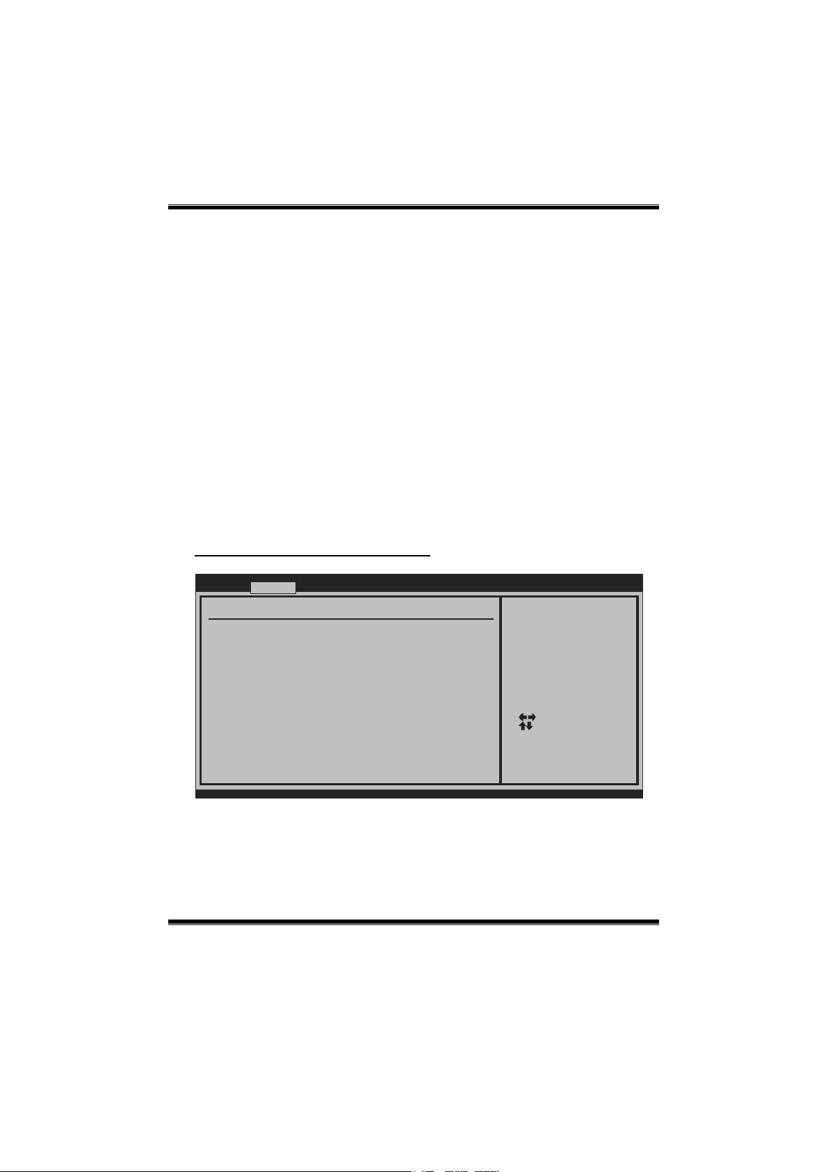
Hyper Transport Configuration
Advanced
Hyper Transport Conf iguration
NODE0:PCI-X2 HT Link
Link Speed [Auto]
Link Width [Auto]
vxx.xx (C)Copyright 1985-200x, American Megatrends, Inc .
BIOS SETUP UTILITY
The Hypertransport
link will run at thi s
speed if it is slower
than or equal to the
system clock and the
board is capable.
Select Screen
Select Item
Change Option
+-
General Help
F1
Save and Exit
F10
Exit
ESC
Link Speed
Optio ns: Auto (Default) / 200MHz / 400MHz / 600MHz / 800MHz / 1GHz
7
Page 9

A740G M2+ BIOS Manual
Link Wid th
Optio ns: Auto (Default) / 8 Bit / 16 Bit
CPU FID/VID Control
Advanced
CPU FID/VID Control
Processor Multiplier [Auto]
Processor Voltage [Auto]
vxx.xx (C)Copyright 1985-200x, American Megatrends, Inc .
BIOS SETUP UTILITY
Options
Processor Multiplier
This item allows you to control the CPU ratio and freq uency.
Optio ns: Auto (Default) / other items differ b y CPU
Processor Voltage
This item allows you to control the CPU voltage.
Optio ns: Auto (Default) / other items differ b y CPU
Select Screen
Select Item
Change Option
+-
General Help
F1
Save and Exit
F10
Exit
ESC
8
Page 10
A740G M2+ BIOS Manual
SuperIO Configuration
Advanced
Configure ITE8718 Su per IO Chipset
Onboard Floppy Contr oller [Enabled]
Serial Port1 Address [3F8/IRQ4]
Parallel Port Addres s [378]
Parallel Port Mode [Normal]
Parallel Port IRQ [IRQ7]
Keyboard PowerOn [Disabled]
Mouse PowerOn [Disabled]
Restore on AC Power Loss [Power Off]
BIOS SETUP UTILITY
Allows BIOS to Enabl e
or Disable Floppy
Controller
Select Screen
Select Item
Change Option
+-
General Help
F1
Save and Exit
F10
Exit
ESC
vxx.xx (C)Copyright 1985-200x, American Megatrends, Inc .
Onboard Floppy Controller
Select enabled if your system has a floppy disk controller (FDC) installed on the
system board and you wish to use it. If you installed another FDC or the system uses
no floppy drive, select disabled in this field.
Optio ns: Enabled (Default) / Disabled
Serial Port1 Address
Select an address and corresponding interrupt for the first and second serial ports.
Optio ns: 3F8/IRQ 4 (Default) / 2F 8/IRQ3 / 3E8/IRQ 4 / 2E8/IRQ3 / Auto / Disabled
Parallel Port Address
This item allows you to determine access onboard parallel port controller with which
I/O Address.
Optio ns: 378 (Default) / 278 / 3BC / Disabled
Parallel Port Mode
This item allows you to determine ho w the parallel port should function.
Options: Normal (Default) Using Parallel port as Standard Printer Port.
EPP Using Parallel Po rt as Enhanced Parallel Port.
ECP Using Parallel port as Extended Capabi lities Port.
ECP+EPP Using Parallel port as ECP & EPP mode.
9
Page 11

A740G M2+ BIOS Manual
Parallel Port IRQ
This item allows you to select the IRQ for the onbo ard parallel port.
Optio ns: IRQ7 (Default) / IRQ5 / Disabled
Keyboard PowerOn
This item allows you to control the keyboard power on function.
Optio ns: Disabled (Default) / Enabled
Mouse PowerOn
This item allows you to control the mouse power on functio n.
Optio ns: Disabled (Default) / Enabled
Restore on AC Power Loss
This setting specifies how your system should behave after a power fail o r interrupts
occurs. By choosing Disabled will leave the computer in the power off s tate.
Choosing Enabled will restore the sys tem to the status before power failure or
interrupt occurs.
Optio ns: Power Off (Default) / Last State
Smart Fan Configuration
Advanced
Smart Fan Configurat ion
CPU Smart Fan [Disabled]
Smart Fan Calibratio n
Control Mode
Fan Ctrl OFF( C)
Fan Ctrl On( C)
Fan Ctrl Start value
Fan Ctrl Sensitive
o
o
vxx.xx (C)Copyright 1985-200x, American Megatrends, Inc .
BIOS SETUP UTILITY
10
When you choice [Aut o]
,[3Pin] or [ 4Pin],
please run the
calibration to define
the Fan p arameters for
Smart Fan control
Select Screen
Select Item
Change Option
+-
General Help
F1
Save and Exit
F10
Exit
ESC
Page 12

A740G M2+ BIOS Manual
CPU Smart Fan
This item allows you to control the CPU Smart Fan function.
Optio ns: Disabled (default) / Auto / 4-pin / 3-pin
Smart Fan Calibration
Choose this item and then the BIOS will auto test and detect the CPU/System fan
functions and show CPU/System fan speed.
Control Mode
This item provides several operatio n modes of the fan.
Optio ns: Quiet / Perfo rmance / Manual
Fan Ctrl OFF(℃)
If the CP U/Sys t em Tempera ture is lower than the s et value, FAN wil l turn off.
Optio ns : 0~127 (℃)
Fan Ctrl On(℃)
CPU/System fan starts to work under smart fan function when arrive this set value.
Optio ns : 0~127 (℃)
Fan Ctr l Start Value
When CPU/System temperature arrives to the set value, the CPU/System fan will
work under S mart Fan F unctio n mod e.
Optio ns : 0~127 (℃)
Fan Ctrl Sensitive
Incr easing the value will raise the speed of CPU/System fan.
Optio ns : 1~127
11
Page 13

A740G M2+ BIOS Manual
Hardware Health Configuration
This item s hows t he system temperature, f an spe ed, and vo ltage infor mat ion.
Advanced
Hardware Hea lth Configuration
H/W Health Function [Enabled]
Shutdown Temperature [Disabled]
SYS
Temperature
CPU Temperature
CPU FAN Speed
SYS FAN Speed
CPU Core
NB Voltage
+3.30V
+5.00V
+12.0V
DDR Voltage
HT Voltage
5VSB
VBAT
vxx.xx (C)Copyright 1985-200x, American Megatrends, Inc .
H/W Health Function
If yo u co mputer co ntains a monitor ing system, it will show PC health status dur ing
POST stage.
Optio ns: Enabled (Default) / Disabled
BIOS SETUP UTILITY
Enables Hardware
Health Monitoring
Device.
Select Screen
Select Item
Change Option
+-
General Help
F1
Save and Exit
F10
Exit
ESC
Shutdow n T emperature
This item allows you to set up the CPU shutdown Temperature. This item is only
effective under Windows 98 ACPI mode.
Optio ns: Disabled (Default) / 70℃/158℉ / 60℃/140℉ / 65℃/149℉ / 75℃/158℉
/ 80℃/158℉ / 85℃/158℉ / 90℃/158℉ / 95℃/158℉
12
Page 14

A740G M2+ BIOS Manual
Power Configuration
Advanced
ACPI Settings
Suspend mode [S1 (POS)]
ACPI Version Feature s [ACPI v1.0]
ACPI APIC support [Enabled]
AMI OEMB table [Enabled]
Headless mode [Disabled]
RTC Resume [Disabled]
Power On by LAN [Disabled]
BIOS SETUP UTILITY
Select the ACPI
state used for
System Suspend.
Select Screen
Select Item
Change Option
+-
General Help
F1
Save and Exit
F10
Exit
ESC
vxx.xx (C)Copyright 1985-200x, American Megatrends, Inc .
Suspend mode
The item allows you to s elect the susp end type und er the ACPI operating syst em.
Options: S1 (POS) (Default) Power on Suspend
S3 (STR) Susp end to RAM
S1 & S3 POS+ST R
ACPI Version Features
The it em a llows yo u to select the vers ion of ACPI.
Options : ACPI v1.0 (Default) / ACPI v2.0
ACPI APIC support
This item is used to enable or disable the motherbo ard's APIC (Advanced
Programmab le Interrupt Contro ller). The APIC provides multiprocessor support,
more IRQs and faster interrupt handling.
Optio ns: Enabled (Default) / Disabled
AMI OEMB table
Set this value to allow the ACPI BIOS to add a pointer to an O EMB table in the Root
System Description Table (RSDT) table.
Optio ns: Enabled (Default) / Disabled
13
Page 15

A740G M2+ BIOS Manual
Headless mode
This is a server-specific feature. A headless server is one that operates without a
keyboard, monitor or mouse. To run in headless mode, both BIOS and operating
system (e.g. Windows Server 2003) must support headless operatio n.
Optio ns: Disabled (Default) / Enabled
RTC Re s ume
When “Enabled”, you can set the date and time at which the RTC (real-time clock)
alarm awakens the system from Suspend mode.
Optio ns: Disabled (Default) / Enabled
Power On by LAN
This item allows you control the wake on LAN (WOL) function.
Optio ns: Disabled (Default) / Enabled
USB Configuration
This item shows the US B co ntroller and using USB d evice information.
Advanced
USB Configuration
Module Version - 2.24.2-13.4
USB Devices Enabled:
Legacy USB Support [Enabled]
USB 2.0 Controller Mode [HiSpeed]
BIOS EHCI Hand-Off [Enabled]
> USB Mass Storage Device Configuration
BIOS SETUP UTILITY
Enables suppor t for
legacy USB. AU TO
option disable s
legacy support if
no USB devices are
connected.
Select Screen
Select Item
Change Option
+-
General Help
F1
Save and Exit
F10
Exit
ESC
vxx.xx (C)Copyright 1985-200x, American Megatrends, Inc.
Legacy USB Support
This item determines if the BIOS should provide legacy support for USB devices
like the keyboard, mouse, and USB drive. This is a useful feature when using such
USB devices with operating systems that do not natively s upport USB (e.g.
Microsoft DOS or Windows NT).
Optio ns: Enabled (Default) / Disabled
14
Page 16

A740G M2+ BIOS Manual
USB 2.0 Controller Mode
This item allows you to select the operation mode of the USB 2. 0 co ntroller.
Options: HiSpeed (Default) USB 2.0-480Mbps
FullSpeed USB 1.1-12Mbps
BIOS EHCI Hand-Off
This item allows you to enable s upport for operating systems witho ut an EHCI
hand-off feature.
Optio ns: Enabled (Default) / Disabled
USB Mass Storage Device Configuration
Advanced
USB Mass Storage Device Configuration
USB Mass Storage Reset Delay [20 Sec]
Device #
Emulation Type [Auto]
vxx.xx (C)Copyright 1985-200x, American Megatrends, Inc.
BIOS SETUP UTILITY
Number of seco nds
POST waits for the
USB mass storage
device after s tart
unit command.
Select Screen
Select Item
Change Option
+-
General Help
F1
Save and Exit
F10
Exit
ESC
USB Mass Storage Reset Delay
This item allows you to set the reset delay for USB mass sto rage device.
Options: 20 Sec (Default) / 10 Sec / 30 Sec / 40 Sec
Emulation Type
This item allows you to select the emulation type o f the USB mass storage device.
Optio ns: Auto (Default) / F lopp y / Forc ed FDD / Hard Disk / CDROM
15
Page 17

A740G M2+ BIOS Manual
3 PCIPnP Menu
This section describes configuring the PCI bus system. PCI, or Personal Computer
Intercon nect, is a system which allows I/ O devic es to oper ate at sp eeds nearing the
speed of the CPU itself uses when communicating with its own special components.
Notice
z Beware of that s etting inappropriate values in items of this menu may cause
system to malfunction.
Main Advanced PCIPnP Boot Chi pset Performance
Advanced PCI /PnP Settings
WARNING: Setting wro ng values in below sections
may cause s ystem to malfunction.
Clear NVRAM [No]
Plug & Play O/S [No]
PCI Latency Timer [64]
Allocate IRQ to PCI VGA [Yes]
Palette Snooping [Disabled]
PCI IDE BusMaster [Enabled]
> PCI Resource
> PCI Express Config uration
BIOS SETUP UTILITY
Clear NVRAM during
System Boot.
Select Screen
Select Item
Change Option
+-
General Help
F1
Save and Exit
F10
Exit
ESC
Exit
vxx.xx (C)Copyright 1985-200x, American Megatrends, Inc .
Clear NVRAM
This item allows you to clear the data in the NVRAM (CMOS) by selecting “Yes”.
Options: No (Default) / Yes
Plug & Play OS
When set to YES, BIOS will only initialize the PnP cards us ed for the boot sequence
(VGA, IDE, SCSI). The rest of the cards wi ll be initialized by the PnP operating
system like W indow™ 95. When set to NO, BIOS will initialize all the PnP cards.
For non-PnP operating systems (DOS, Netware™ ), this option must set to NO.
Options: No (Default) / Yes
16
Page 18

A740G M2+ BIOS Manual
PCI Latency Timer
This item controls how long a PCI device can hold the PCI bus before another takes
over. The longer the latency, the longer the PCI device can retain control of the bus
before handing it over to another PCI device.
Optio ns : 64 ( Default) / 0-255
Allocate IRQ to PCI VGA
This item allows BIOS to c hoos e a IRQ to ass ign for the PCI VGA c ard.
Optio ns: Yes (Def ault) / No
Palett e Snooping
Some old graphic cont ro llers need to “snoop ” on the VGA palet te a nd then map it to
their disp lay as a way to provid e boot information and VGA compatibility. This item
allows such snooping to take place.
Optio ns: Disabled (Default) / Enab led
PCI IDE BusMaster
This item is a toggle for the built-in driver that allows the onboard IDE controller to
perform D MA (Direct Memo ry Access) transfers.
Optio ns: Enabled (Default) / Disabled
PCI Resource
PCIPnP
PCI Resource
IRQ3 [Available]
IRQ4 [Available]
IRQ5 [Available]
IRQ7 [Available]
IRQ9 [Available]
IRQ10 [Available]
IRQ11 [Available]
IRQ14 [Available]
IRQ15 [Available]
DMA Channel 0 [Available]
DMA Channel 1 [Available]
DMA Channel 3 [Available]
DMA Channel 5 [Available]
DMA Channel 6 [Available]
DMA Channel 7 [Available]
Reserved Memory Size [Disabled]
vxx.xx (C)Copyright 1985-200x, American Megatrends, Inc.
BIOS SETUP UTILITY
17
Available: Spe cified
IRQ is availab le to be
used by PCI/Pn P
devices.
Reserved: Specified
IRQ is reserved for
use by Legacy ISA
devices.
Select Screen
Select Item
Change Option
+-
General Help
F1
Save and Exit
F10
Exit
ESC
Page 19

A740G M2+ BIOS Manual
IRQ3/4/5/7/9/10/11/14/15
Thes e items wi ll allow you to assign each system interrupt a type, depending on the
type o f d evice using th e interr upt. The option “ Ava ilab le ” me ans t he IRQ is go ing
to ass ign auto matically.
Optio ns: Available (Default)
DMA Channel 0/1/3/5/6/7
These items will allow you to assign each DMA channel a type, depending on the
type o f d evice using the c hannel. The op t ion “ Availab le” means the cha nnel is
going to assign auto matically.
Optio ns: Available (Default)
Reserved Memory Size
This item allows BIOS to reserve certain memory size for specific PCI d evice.
Optio ns: Disabled (Default) / Enab led
PCI Express Configuration
PCIPnP
PCI Express Configuration
Active State Power-Management[Disabled]
BIOS SETUP UTILITY
Enable/Disable
PCI Express L0s and
L1 link power
states.
Select Screen
Select Item
Change Option
+-
General Help
F1
Save and Exit
F10
Exit
ESC
vxx.xx (C)Copyright 1985-200x, American Megatrends, Inc.
Active State Power-Management
This item sets the ASPM configuration for the PCI Express devic es befor e the
operating sys tem boots. This function is for OS which does not support ASPM.
Optio ns: Disabled (Default) / Enab led
18
Page 20

A740G M2+ BIOS Manual
4 Boot Menu
This menu allows you to se tup the s ystem boo t opt io ns.
Main Advanced PCIPnP Boot Chipset Performance
Boot Settings Config uration
> Boot Device Priori ty
> Hard Disk Drives
> Removable Drives
> CD/DVD Drives
Quick Boot [Enabled]
AddOn ROM Display Mo de [Force BIOS]
Bootup Num-Lock [ON]
Interrupt 19 Capture [Enabled]
BIOS SETUP UTILITY
Exit
Specifies the
Boot Device
Priority seq uence.
Select Screen
Select Item
Go to Sub Screen
Enter
General Help
F1
Save and Exit
F10
Exit
ESC
vxx.xx (C)Copyright 1985-200x, American Megatrends, Inc .
Boot Device Priority
Items in this sub-menu specify the boot d evice priority sequence from the available
devices. The number of device items that appears on the screen depends on the
number of devices ins talled in the system.
Optio ns: Removable / Hard Disk / CDROM / Legacy LAN / Disabled
Hard Disk Drives
The BIOS will attempt to arrange the hard disk boot sequence automatically. You
can also change the booting sequence. The number of device items that appears on
the screen depends on the number of devices installed in the system.
Optio ns: Pri. Master / Pri. Slave / Sec. Master / Sec. Slave / USB HDD0 /
USB HDD1 / US B HDD2 / Bootable Add -in Cards
Removable Drives
The BIOS will attempt to arrange the removable drive boot sequence automatically.
You can also change t he booting sequenc e. The numb er of d evice ite ms that
appears on the screen depends on the number of d evices installed in the system.
Options: Floppy Disks / Zip100 / USB-FDD0 / USB-FDD1 / USB-ZIP0 /
USB-ZIP1 / LS120
19
Page 21

A740G M2+ BIOS Manual
CD/DVD Drives
The BIOS will attempt to arrange the CD/DVD d rive boot seq uence automatically.
You can also change t he booting sequenc e. The numb er of d evice ite ms that
appears on the screen depends on the number of d evices installed in the system.
Optio ns: Pri. Mast er / Pri. Slave / S ec. Mas t er / S ec. Slave / US B C DROM0 /
USB CDRO M 1
Quick Boot
Enabling this option will cause an abridged version of the Power On Self-Test
(POS T) to execute after you power up the comput er.
Optio ns: Enabled (Default) / Disabled
AddOn ROM Display Mode
This item sets the display mode for op tion ROM.
Options: Force BIOS (Default) / Keep Current
Bootup Num-Lock
Selec ts the NumLoc k State after the system s witc hed o n.
Options: ON (Default) / OFF
Interrupt 19 Capture
When set to Enabled, this item allows the opt ion ROMs to trap interrupt 19.
Optio ns: Enabled (Default) / Disabled
20
Page 22

A740G M2+ BIOS Manual
5 Chipset Menu
This submenu allows you to configure the specific features of the chipset installed on
your system. This chipset manage bus speeds and access to system memory
resources, such as DRAM. It also coordinates communications with the PCI bus.
Main Advanced PCIPnP Boot Chipset Performance
> NorthBridge Configuration
> SouthBridge Configuration
> AMD 690G/740 Confi guration
> OnBoard Pe ripherals Configuration
BIOS SETUP UTILITY
Options for NBAdvanced Chi pset Settings
Select Screen
Select Item
Go to Sub Screen
Enter
General Help
F1
Save and Exit
F10
Exit
ESC
Exit
vxx.xx (C)Copyright 1985-200x, American Megatrends, Inc .
NorthBridge Configuration
NorthBridge Chipset Configurati on
> Memory Configuration
> ECC Configuration
> DRAM Timing Config uration
Memory CLK
CAS Latency(Tcl)
RAS/CAS Delay(Trcd )
Row Precharge Time (Trp)
Min Active RAS(Tras)
RAS/RAS Delay(Trrd )
Row Cycle (Trc)
vxx.xx (C)Copyright 1985-200x, American Megatrends, Inc .
BIOS SETUP UTILITY
Chipset
21
Select Screen
Select Item
Go to Sub Screen
Enter
General Help
F1
Save and Exit
F10
Exit
ESC
Page 23

A740G M2+ BIOS Manual
Memory Configuration
BIOS SETUP UTILITY
Memory Configuration
Bank Interleaving [Auto]
Channel Interleaving [Auto]
Enable Clock to All DIMMs [Disabled]
MemClk Tristate C3/A TLVID [Disabled]
Memory Hole Remappin g [Enabled]
Unganged Mode suppor t [Enabled]
Power Down Enable [Enabled]
Power Down Mode [Channel]
vxx.xx (C)Copyright 1985-200x, American Megatrends, Inc .
Chipset
Enable Bank Memory
Interleaving
Select Screen
Select Item
Change Option
+-
General Help
F1
Save and Exit
F10
Exit
ESC
Bank Interleaving
Bank Interle aving is an advanced chipset techniq ue used to improve memory
performance. Memory interleaving inc reas es bandwid th by allowing simultaneo us
access to more than one piece o f memory.
Optio ns: Auto (Default)
Channel Interl eaving
This item allows you to control the DDR2 dual-channel func tion.
Optio ns: Auto (Default) / XOR of Address bit
Enable Clock to All DIMMs
This item determines whether the BIOS should actively reduc e EMI
(Electromagnetic Interference) and reduce power consumption by turning off
unocc upied or inactive DIM M slots.
Optio ns: Disabled (Default) / Enab led
MemClk Tristate C3/ATLVID
This item enables or d isables the MemClk Tristate function in C3 Mode.
Optio ns: Disabled (Default) / Enab led
Memory Hole Remapping
This item allows you to enable or disable the remapping of the overlapped PCI
memo ry above the total physical memory. Only 64-bit OS supports this function.
Optio ns: Enabled (Default) / Disabled
22
Page 24

A740G M2+ BIOS Manual
Unganged Mode Support
This item controls the DRAM controller ganged (128bit*1) / unganged (64b it*2)
dual-channel operation mode. If two DRAM modules with different size are
installed, using unganged mode can still make it run in dual-channel operatio n.
Optio ns: Enabled (Default) / Disabled
Power Down Enable
This item controls t he DRAM po wer do wn function.
Optio ns: Enabled (Default) / Disabled
Power Down Mode
This item allows you to select the DRAM power down mode.
Optio ns: Channel (Default ) / CS
ECC Configuration
BIOS SETUP UTILITY
ECC Configuration
ECC Mode [Disabled]
DRAM ECC Enable [Disabled]
DRAM SCRUB REDIREC T [Disabled]
4-Bit ECC Mode [Disabled]
DRAM BG Scrub [Disabled]
Data Cache BG Scru b [Disabled]
L2 Cache BG Scrub [Disabled]
L3 Cache BG Scrub [Disabled]
vxx.xx (C)Copyright 1985-200x, American Megatrends, Inc .
Chipset
Set the level of ECC
protection. Note: The
Super ECC mode
dynamically sets the
DRAM scrub rate so
all of memory is
scrubbed in 8 hours.
+F1
F10
ESC
ECC Mode
This item allows you to select the DRAM EC C Mode.
Optio ns: Disabled (Default) / Basic / Good / Super / Max / User
DRAM ECC Enabled
Optio ns: Disabled (Default) / Enab led
DRAM Scrub Redirect
Optio ns: Disabled (Default) / Enab led
Select Screen
Select Item
Change Option
General Help
Save and Exit
Exit
23
Page 25

A740G M2+ BIOS Manual
4-bit ECC Mode
Optio ns: Disabled (Default) / Enab led
DRAM BG Scrub/Data Cache BG Scrub/L2 Cache BG Scrub/L3 Cache BG Scrub
Options: Disabled (Default)
DRAM Timing Configuration
BIOS SETUP UTILITY
DRAM Timing Configur ation
Memory Clock Mode [Auto]
DRAM Timing Mode [Auto]
vxx.xx (C)Copyright 1985-200x, American Megatrends, Inc .
Chipset
Select the DRAM
Frequency programming
method. If A uto,
the DRAM speed will
be based on SPDs.
If Limit, the DRAM s pe
will not exceed the
specified value. If
Manual, the DRAM speed
specified will be
programmed regardles s.
Select Screen
Select Item
Change Option
+-
General Help
F1
Save and Exit
F10
Exit
ESC
Memory Clock Mode
This item allows you to control the Memory Cloc k.
Optio ns: Auto (Default) / Manual
DRAM Timing Mode
This item allo ws you to choose to manually or automatically regulate the DRAM
Timing.
Optio ns: Auto (Default) / MaxMemClk
24
Page 26

A740G M2+ BIOS Manual
SouthBridge Configuration
BIOS SETUP UTILITY
> SB Azalia Audio Co nfiguration
OHCI HC(Bus 0 Dev 18 Fn o) [Enabled]
OHCI HC(Bus 0 Dev 18 Fn 1) [Enabled]
EHCI HC(Bus 0 Dev 18 Fn 2) [Enabled]
OHCI HC(Bus 0 Dev 19 Fn 0) [Enabled]
OHCI HC(Bus 0 Dev 19 Fn 1) [Enabled]
EHCI HC(Bus 0 Dev 19 Fn 2) [Enabled]
OHCI HC(Bus 0 Dev 20 Fn 5) [Enabled]
OnChip SATA Channel [Enabled]
OnChip SATA Type [Native IDE]
SATA IDE Combined Mo de [Enabled]
Flash Controller [Disabled]
SB CIM Version
Chipset
Options for SB HD Az al
Select Screen
Select Item
Go to Sub Screen
Enter
General Help
F1
Save and Exit
F10
Exit
ESC
vxx.xx (C)Copyright 1985-200x, American Megatrends, Inc .
SB Azalia Audio Configuration
BIOS SETUP UTILITY
HD Audio Azalia Devi ce [Enabled]
HD Onboard PIN Confi g [Enabled]
Azalia Front Panel [Auto]
SDIN0 Pin Config [Azalia]
SDIN1 Pin Config [Azalia]
SDIN2 Pin Config [Azalia]
SDIN3 Pin Config [Azalia]
Azalia Snoop [Disabled]
vxx.xx (C)Copyright 1985-200x, American Megatrends, Inc .
Chipset
Options
Auto
Disabled
Enabled
Select Screen
Select Item
Change Option
+-
General Help
F1
Save and Exit
F10
Exit
ESC
HD Audi o Azalia Device
This item allows you to control the HD audio devic e.
Optio ns: Enabled (Default) / Disabled
HD Onboard PIN Config
This item allows you to configure the pin definition of the onboard HD header.
Optio ns: Enabled (Default) / Disabled
25
Page 27

A740G M2+ BIOS Manual
Azalia Front Panel
This item controls the HD front panel header function.
Optio ns: Auto (Default) / Disab led
SDIN0/1/2/3 Pin Config
Options: Azalia (Default) / AC’97
Azalia Snoop
This item controls the HD snoop func tion.
Optio ns: Disabled (Default) / Enab led
OHCI HC(Bus 0 Dev 18/19/20 Fn 0/1/5)
Optio ns: Enabled (Default) / Disabled
EHCI HC(Bus 0 Dev 18/19 Fn 2)
Optio ns: Enabled (Default) / Disabled
OnChip SAT A Channel
This optio n allows you to enable the o n-chip Serial ATA.
Optio ns: Enabled (Default) / Disabled
OnChip SAT A Type
This optio n allows you to select the on-chip Serial ATA operation mode.
Optio ns: Native IDE (Default) / R AID / AHCI / Legacy IDE / IDEÆAHCI
SAT A IDE Combined Mode
This optio n controls the SATA/PATA combined mode.
Optio ns: Enabled (Default) / Disabled
Flash Controller
This item allows you to control the flash controller.
Optio ns: Disabled (Default) / Enab led
26
Page 28

A740G M2+ BIOS Manual
AMD 690G/740 Configuration
BIOS SETUP UTILITY
AMD 690G/740 Configu ration
> Internal G raphics Configurati on
> PCI Express Config uration
NB Azalia [Enable]
Chipset
Internal Gra phics Conf
Select Screen
Select Item
Go to Sub Screen
Enter
General Help
F1
Save and Exit
F10
Exit
ESC
vxx.xx (C)Copyright 1985-200x, American Megatrends, Inc .
Internal Graphics Configuration
BIOS SETUP UTILITY
Internal Gra phics Configuration
Internal Graphics Mo de [UMA]
UMA Frame Buffer S ize [Auto]
Current UMA Size [128MB]
Graphics Clock Mode [Sync]
Multifunction [Disabled]
Surround View [Disabled]
Primary Video Contro ller [PCIE/IGFX/PCI]
vxx.xx (C)Copyright 1985-200x, American Megatrends, Inc .
Chipset
Options
Disable
UMA
Select Screen
Select Item
Change Option
+-
General Help
F1
Save and Exit
F10
Exit
ESC
Internal Graphics Mod e
This item allows you to select the memory mode used for internal graphics device.
Opt ions: UMA (Default ) / Dis able
UMA Frame Buffer Size
This item allows you to choose the UMA frame buffer size for internal graphics.
Optio ns: Auto (Default) / 16M / 32M / 64M / 128M / 256M / 512M / Disabled
27
Page 29

A740G M2+ BIOS Manual
Current UMA Size
This item shows the current UMA size.
Graphics Clock Mode
This item allows you to select the graphics c lock mode.
Optio ns: Sync (Default) / AS ync
Multifunction
This item allows you to disabled / enabled multifunct ion device.
Optio ns: Disabled (Default) / Enab led
Surround View
This item allows you to control the S urround View Functio n.
Optio ns: Disabled (Default) / Enab led
Primary Video Controller
This item allows you to select the primary video contro ller.
Optio ns: PCIE/IGFX/PCI (Def ault) / PCIE / IGFX / PCI
PCI Express Configuration
BIOS SETUP UTILITY
PCI Express Configur ation
PCIE GFX0 Link Width [Auto]
PCIE GFX Overclockin g [Disabled]
NB-SB PCIE Link ASPM [Disabled]
GFX PCIE Link ASPM [Disabled]
GPP PCIE Link ASPM [Disabled]
GFX0 Slot Power Limi t, W [75]
GPP Slots Power Limi t, W [25]
vxx.xx (C)Copyright 1985-200x, American Megatrends, Inc .
PCIE GFX0 Link Width
Optio ns: Auto (Default) / x1 / x2 / x4 / x8 / x16
PCIE GFX Ov erclocking
Optio ns: Disabled (Default) / Enab led
Chipset
28
Options
Auto
x1
x2
x4
x8
x16
Select Screen
Select Item
Change Option
+-
General Help
F1
Save and Exit
F10
Exit
ESC
Page 30

A740G M2+ BIOS Manual
NB-SB PCIE Link ASPM
Optio ns: Disabled (Default) / Enab led
GFX PCIE Link ASP M
Optio ns: Disabled (Default) / Enab led
GPP PCIE Link ASPM
Optio ns: Disabled (Default) / Enab led
GFX0 Slot Power Limit, W
Optio ns : 75 ( Default) / 0-255
GPP Slot Power Limit, W
Optio ns : 25 ( Default) / 0-255
NB Aza lia
This item allows you to control the northbridge HD azalia function.
Optio ns: Enabled (Default) / Disabled
OnBoard Peripherals Configuration
BIOS SETUP UTILITY
MAC ID Information 00-E0-4C-36-00-04
Realtek PCIE NIC [Enable]
Realtek Option ROM [Disabled]
Chipset
Enable/Disable
Onboard Broadcom
PCIE Network
Controller
vxx.xx (C)Copyright 1985-200x, American Megatrends, Inc .
MAC ID Information
This item shows the MAC ID.
29
Select Screen
Select Item
Change Option
+-
General Help
F1
Save and Exit
F10
Exit
ESC
Page 31

A740G M2+ BIOS Manual
Realtek PCIE NIC
This optio n allows you to co ntrol the onboard LAN co ntroller.
Optio ns: Enable (Default) / Disable
Realtek Option ROM
This item allows you to enable or disable t he Onbo ard LAN Boot R O M.
Optio ns: Disabled (Default) / Enab led
30
Page 32

A740G M2+ BIOS Manual
6 Performance Menu
This submenu allows you to change voltage and clock of various devices.
(However, we suggest you to use the default setting. Chan ging the voltag e and c lock
improperly may damage the device.)
Notice
z Beware of that s etting inappropriate values in items of this menu may cause
system to malfunction.
Main Advanced PCIPnP Boot Chi pset Performance
Performance Settings
WARNING: Setting wro ng values in below sections
may cause s ystem to malfunction.
CPU Overvoltage [StartUp]
Memory Overvoltage [1.95V]
Chipset Overvoltage [1.15V]
HT Overvoltage [1.20V]
CPU Frequency [200]
BIOS SETUP UTILITY
Change CPU voltage
value.
Select Screen
Select Item
Change Option
+-
General Help
F1
Save and Exit
F10
Exit
ESC
Exit
vxx.xx (C)Copyright 1985-200x, American Megatrends, Inc .
CPU Overvoltage
This item allows you to select CPU Voltage Contro l.
Optio ns: StartUp (Default)
Memory O vervoltage
This item allows you to select DDR Voltage Control.
Options: 1.95V (Default) / 2.00V / 2.05V / 2.10V
Chipset Overvoltage
This item allows you to select NB/SB Voltage Co ntrol.
Optio ns: 1.15V (Default) / 1. 20V / 1.25V / 1.30V / 1.35V / 1.40V
31
Page 33

A740G M2+ BIOS Manual
HT Overvoltage
This item allows you to select HT Voltage Contro l.
Optio ns: 1. 20V (Default) / 1. 25V / 1.30V / 1.35V / 1.40V
CPU Frequency
This item allows you to select the CPU Frequency.
Options: 200 (MHz) (Default) / 200-600
32
Page 34

A740G M2+ BIOS Manual
7 Exit Menu
This menu allows you to load the optimal default settings, and save or discard the
changes to the BIOS items.
Main Advanced PCIPnP Boot Chi pset Performance
Exit Options
Save Changes and Exi t
Discard Changes and Exit
Discard Changes
Load Optimal Default s
Security Set tings
> Security
BIOS SETUP UTILITY
Exit
Exit system setup
after saving the
changes.
F10 key can be used
for this operation.
Select Screen
Select Item
Go to Sub Screen
Enter
General Help
F1
Save and Exit
F10
Exit
ESC
vxx.xx (C)Copyright 1985-200x, American Megatrends, Inc .
Save Changes and Exit
Save all configuration changes to CMOS RAM and exit setup.
Discard Changes and Exit
Abandon all changes made during the current session and exit setup.
Discard Changes
Abandon all changes made during the current session and restore the previously
saved values.
Load Optimal Defaults
This s elec tion allows you to reload the BIOS when problem occurs d uring system
booting sequence. These configurations are factory settings optimized for this
system.
33
Page 35

A740G M2+ BIOS Manual
Security
This sub -menu allows you to provide/revise supervisor and user password.
Security Set tings
Supervisor Password :Not Installed
User Password :Not Installed
Change Supervisor Pa ssword
Change User Password
Boot Sector Virus Pr otection [Disabled]
BIOS SETUP UTILITY
Exit
Install or Change th e
password.
Select Screen
Select Item
Change
Enter
General Help
F1
Save and Exit
F10
Exit
ESC
vxx.xx (C)Copyright 1985-200x, American Megatrends, Inc .
Change Supervis or Pa ssword
Setting the supervisor password will pro hib it everyone except the supervisor from
making changes using the CMOS S etup Utility. Yo u will be promp ted with to enter a
pass word.
Change User Password
If the Supervisor Password is not set, then the User Password will function in the
same way as the Supervisor Password. If the Supervisor Password is set and the User
Pass word is set, the “User” will only be able to view configurations but will not be
able to change them.
Boot Sector Virus Protection
This option allows you to c hoos e the VIRUS Warning feat ure that is us ed to protect
the IDE Hard Disk boot sector. If this function is enabled and an attempt is made to
write to the boot sector, BIOS will display a warning message on the screen and
sound an alar m beep.
Optio ns: Disabled (Default) / Enab led
34
 Loading...