

Page 1

A740G M2+ Set up Manual
FCC Inf or m at ion and Copyri ght
This equipment has been tested and found to comply with the limits of a Class
B digital devic e, pursuant to Part 15 of the FCC Rules. These limits are designed
to provide reas onable protec tion ag ai nst harmful i nterfe rence in a resi dentia l
installation. T his equipment generates, uses , and can radiate radio frequency
energy and, if not ins talled and used in accordance with the instructions , may
cause harmful interference to radio communications. There is no guarantee
that interfe rence will not occur in a particular ins tallati o n.
The vendor makes no re p res e ntatio ns o r wa rran ties wi th r espec t to t he
contents here and specially disclaims any implied warranties of merchantability
o r fi tnes s fo r any pu rpose . F u rt he r the ve nd o r rese rves the ri ght to rev is e this
publication and to make changes to the contents here without obligation to
notify any party beforehand.
D uplic a tion of t his publicat io n, in part or i n whole , is no t allowed without fi rst
obtaining the vendor’s approval in writing.
The content of this user’s manual is subject to be changed without notice and
we will not be res ponsible for any mistakes fo und in this use r’s manual. A l l the
brand and product names are trademarks of their respective companies.
Page 2

Table of Cont ent s
Chapter 1 : In tro d u c tion.....................................................1
1.1 Before You Start................................................................... 1
1.2 Package Checklist................................................................ 1
1.3 Motherboard Features..........................................................2
1.4 Rear Panel Connectors.......................................................... 3
1.5 Mo t he r bo ar d Layou t............................................................4
Chapter 2 : Hardware In s tallation........................................5
2.1 Installing Ce ntral Proce ssing Unit (CPU)................................ 5
2.2 FAN Heade rs........................................................................ 7
2.3 Installing Sy stem Memory......................................................8
2.4 Con nec tors and Slo ts............................................................10
Chapter 3: H ead er s & Jumpers Setu p..............................12
3.1 How to Setu p Jum pers..........................................................12
3.2 Det ail Settin gs.....................................................................12
Chapter 4 : RA ID Fu n c tions...............................................19
4.1 Operatio n Syste m................................................................19
4.2 Raid Array s.........................................................................19
4.3 How RAI D Work s.................................................................19
Chapter 5 : U s eful Help.....................................................22
5.1 Driver Instal latio n Note.......................................................22
5.2 Software .............................................................................23
5.3 Extra Informati on ................................................................27
5.4 Troubleshooting ...................................................................29
Appenden cies: S PEC In Other L an g u a g e.............................30
German................................................................................................30
France..................................................................................................32
Italian..................................................................................................34
Spanish................................................................................................36
Portuguese...........................................................................................38
Polish...................................................................................................40
Russian ................................................................................................42
Arabic..................................................................................................44
Japanese ..............................................................................................46
Page 3
A740G M2+
CHAPTER 1: INTRODUCTION
1.1 BEFORE YOU START
Tha nk you for choosing our p ro duct. Before yo u start ins talling the
mo the rboa rd, plea se make su re you follo w the ins tructio ns be low:
Prepare a dry and stable working environment with
s uf ficie nt li gh ting .
Always disconnect the computer from power outlet
be fo re ope ra tion .
Befo re you tak e the mo the rboa rd o u t f rom a n ti -s ta ti c
bag, ground yourself properly by touching any safely
grounded appliance, o r use grounded wrist s trap to
remove the static charge.
Avo id tou ch ing the compone nts on mo the rboa rd o r the
rea r side of the board unless ne cessary. Hold the bo ard
on the edge , do not try to bend o r flex the board.
Do no t lea ve any un fastene d small parts inside the
case after installation. Loose parts will cause short
circuits wh ich may damage the equipmen t.
Keep the computer from dangerous area, such as heat
sou rce, humid air and water.
1.2 PACKAGE CHECKLIST
HDD Cable X 1
Se ria l ATA Cab le X 1
Rear I/O Panel for ATX Case X 1
I ns talla tion Guide X 1
Fu lly Se tup D rive r C D X 1 (full ve rs ion manua l f iles ins ide )
FDD Cable X 1 (optional)
USB 2.0 Cable X1 (optional)
S/P DI F ou t Ca ble X 1 (op tiona l)
Se ria l ATA P o we r Cab le X 1 (o ptio nal)
Note: The package contents may differ by area or your motherboard version.
1
Page 4
Motherboard Manual
/
2
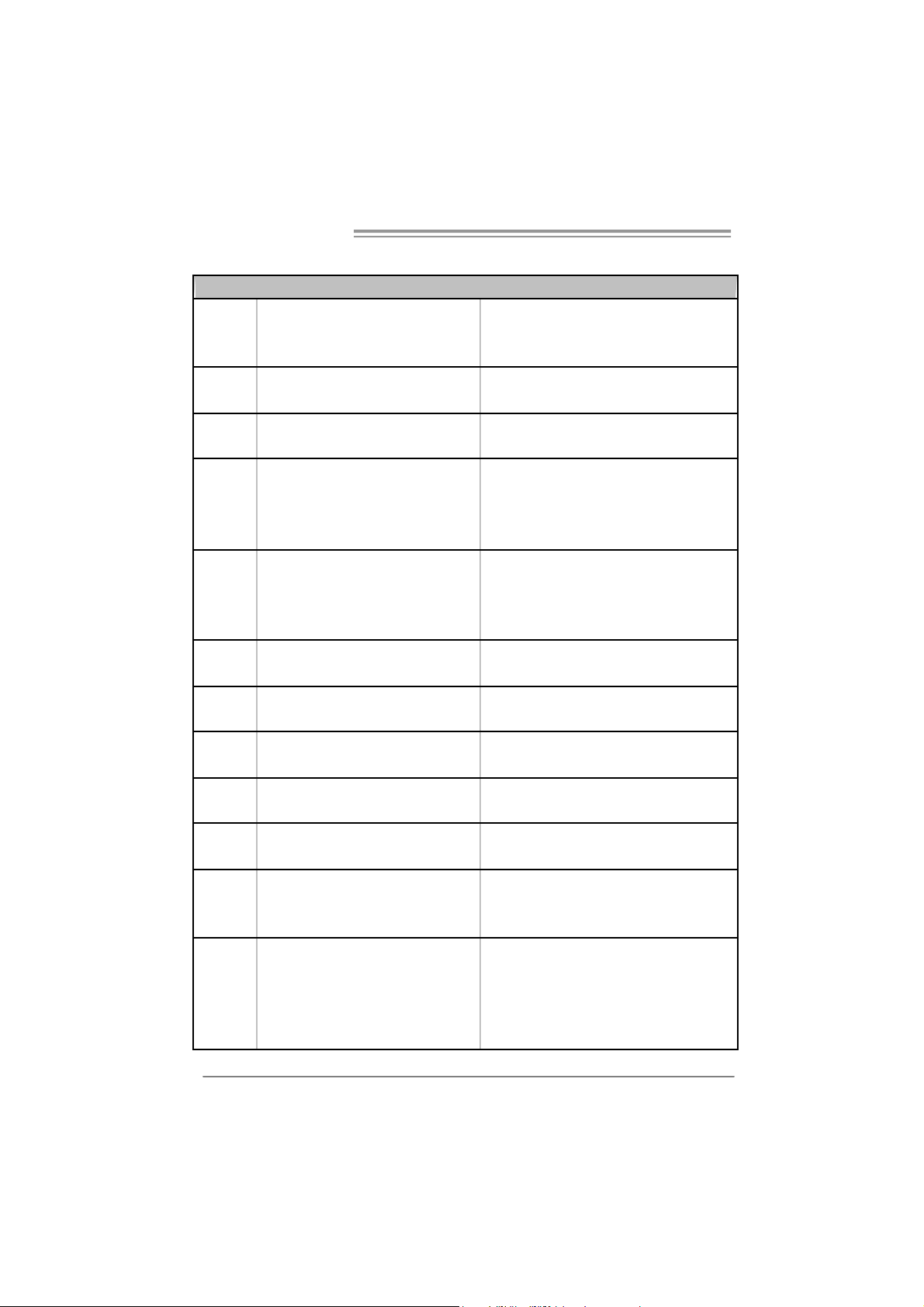
1.3 MOTHERBOARD FEATURES
S ocket AM 2+ / AM 2
CPU
FSB
Chipset
Super I/O
Main
Memory
Graphics Int egrated in AM D 740G Chipset
IDE Integrated IDE Controller
SA TA II I nt e grat e d S e ria l ATA C o nt r ol l er
LA N Realt ek RTL 8101E
Sound ALC662
Slots
On Board
Connector
AM D Athl on 64 / A t hl on 64 FX
/ Sempron / Phenom processors
Support HyperTrans port 2.0
Supports up to 2.0 GT/s Bandwidth
AM D 74 0G
AM D S B700
ITE 8718F
Provides t he most c ommonly used legacy
Sup er I /O functionality
DDR2 DIMM Slots x 4
Max Memory Capacity 8GB
Eac h DIMM s upports 256/512MB/1GB/2GB
DDR2
PCI Express x16 slot x1 Supports PCI-E x16 expansion cards
PCI Express x1 slot x1 Supports PCI-E x1 expansion cards
PCI slot x2 Supports PCI expansion cards
Floppy connector x1 Each connector supports 2 Floppy drives
IDE Connector x1 Each connector supports 2 IDE device
SATA Connector x6 Each connector supports 1 SATA devices
Front Panel Connector x1 Supports front panel facilities
Front A udio Connector x1 Supports front panel audio function
Athlon 64 x
SPEC
AM D 64 Architecture enables 32 and 64 bit
computing
Supports Hyper Transport 2.0 and Cool=n=Quiet
Low Pin Count Interface
Environment Control initiatives
H/W Monitor
ITE's "Smart Guardian" function
Dual Channel Mode DDR2 memory module
Supports DDR2 533 / 667 / 800
Supports DDR2 1066 (for AM2+ CPU only)
Registered DIMM and ECC DIMM is not s upported
Max Shared Video Memory is 512MB
HDCP support
Ultra DMA 33 / 66 / 100 / 133 Bus Master Mode
supports PIO M ode 0~4,
Data transfer rates up to 3 Gb/s
SATA Version 2.0 specification compliant
10 / 100 Mb/s auto negotiation
Half / Full duplex capability
5.1 channels audio out
High Definition Audio
2
Page 5
SPEC
CD-in Connector x1 S upports C D audio-in functi on
S/PDIF out connector x1 Supports digital audio out function
CPU Fan header x1 CPU Fan power supply (with Smart Fan function)
System Fan header x1 System Fan Power supply
CMOS clear header x1 Restore CMOS data t o factory default
USB connector x3 Each connector supports 2 front panel USB ports
Power Connector (24pin) x1 Connects to Power supply
Pow er Connector (4pin) x1 Connects to Power supply
Printer Port Connector x1 Each connector supports 1 Printer port
Serial port Connector x1 Connects to RS-232 Port
PS/2 Keyboard x1
PS/2 Mouse x1
Back Panel
I/O
Board Size 215 mm (W) x 244 mm(L)
Special
Features
OS SupportWindows XP / VISTA
DVI port x1
VGA port x1
LAN port x1
USB Port x4
Audio Jack x3
RAID 0 / 1 / 1+ 0 support
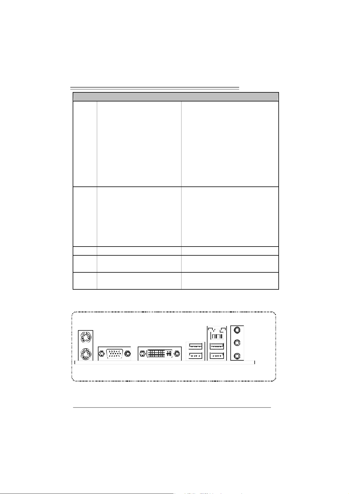
1.4 R
EAR PANEL CONNECTORS
A740G M2+
Connects to PS/2 Keyboard
Connects to PS/2 Mouse
Co nnec t t o DV I- D mo nit or
Connect to D-SUB m onitor
Connect t o RJ-45 ethernet cable
Connect to USB devices
Provide Audi o-In/Out and microphone connection
Biostar Reserves the right to add or remove support
for any OS With or without notice.
PS/ 2
Mouse
PS/2
Keyboard
VGA
DVI-D
LAN
Li n e In/
Surround
Li n e Ou t
Mi c In 1/
Bass/ Center
USBX2USBX2
3
Page 6
Motherboard Manual
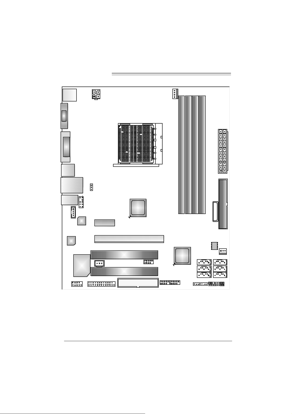
1.5 MOTHERBOARD LAYOUT
JKBMS1
VGA
DVI
JUSB1
JUSBLAN1
JAUDIO1
JCDIN1
JAUDIOF1
LAN
JATXPWR2
JUS BV1
PEX1 _1
AMD
740G
Socket AM2+
JCFAN1
DI MMA1
JATXPWR1
DI MMB1
DI MMA2
DI MMB2
IDE 1
BAT TERY
4
Codec
Sup e r I/ O
JCOM1
Not e: represents the 1■
JPRNT1
JSPDIF_OUT1
PEX16_1
PCI1
PCI2
FDD1
st
pin.
JUSB4
JUSB3 JUSB2
AMD
SB700
JUSBV 2
SATA3
SATA1
SATA5 SATA6
JCMOS1
JPANEL1
JSFAN1
BI OS
SATA2
SATA 4
Page 7
CHAPTER 2: HARDWARE INSTALLATION
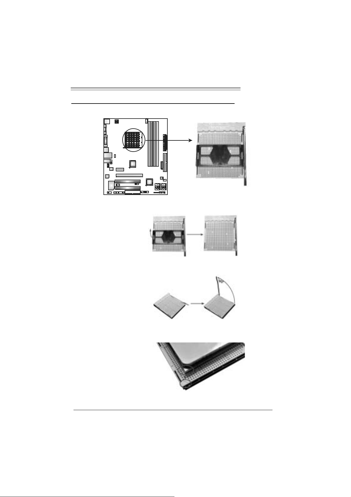
2.1 INSTALLING CENTRAL PROCESSING UNIT (CPU)
Step 1: Remove the socket protection cap.
Step 2: Pull the lever toward direction A from the socket and then raise the
lever up to a 90-degree angle.
A740G M2+
Step 3: Look for the white tri angle on socket, and the gold triangle on
CPU should point towards this white tri angle. The CPU will fit only
in th e cor r ec t or i en tatio n.
5
Page 8
Motherboard Manual
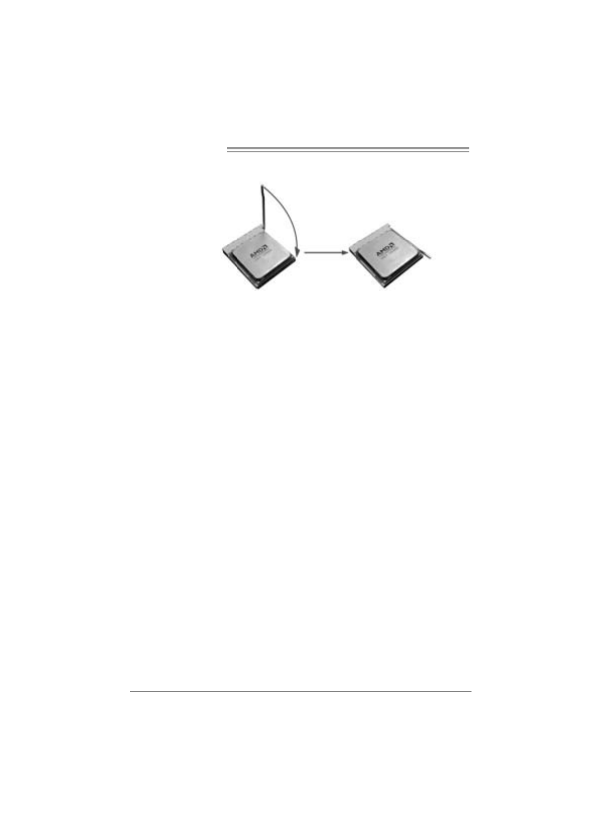
Step 4: Hold the CPU down firmly, and then close the lever toward direct
B to complete the insta llation.
Step 5: Put th e CP U Fan on t he CP U and bu c kl e it . Co nn ec t the CPU
FAN power cable to the JCFAN1. Thi s completes the installation.
Note: Please update the B IOS to the latest version wh ile using AM2+ CP Us . Due to the latest CPU
transition, you may encounter the sit uation that the new system fail ed to boot while using new
AM2+ CPUs. In this case, please i nstall one standar d AM2 CPU to boot your s ystem, and
update the latest BIOS from our website f or AM2+ CPUs support.
6
Page 9
A740G M2+
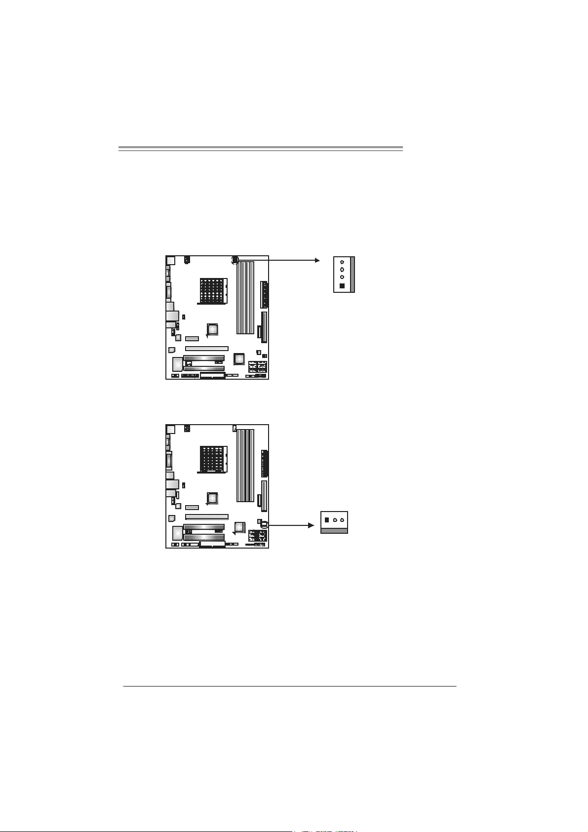
2.2 FAN HEADERS
These fan headers support cooling-fans built i n the computer. The fan
cable and connector may be different according to the fan m anufacturer.
Connect the fan cable to the connector while matching the black wire to
pin#1.
JCFAN1: CPU Fan Header
4
1
JSFAN1: S ystem Fan Header
13
Pin
Assignment
1 Ground
2 +12V
3
FAN RPM rate
sense
4 Smart Fan
Control (By Fan)
Pin
Assignment
1 Ground
2 +12V
3 FAN RPM rate
sense
Note:
The JCFAN1 supports 4-pin head c onnector. The J SFAN1 supports 3-pin head
connector. When connecti ng with wires onto connectors, pl ease note that the r ed wire is
the positi ve and should be connect ed to pin#2, and the black wire is Ground and s hould
be connected to GND.
7
Page 10
Motherboard Manual
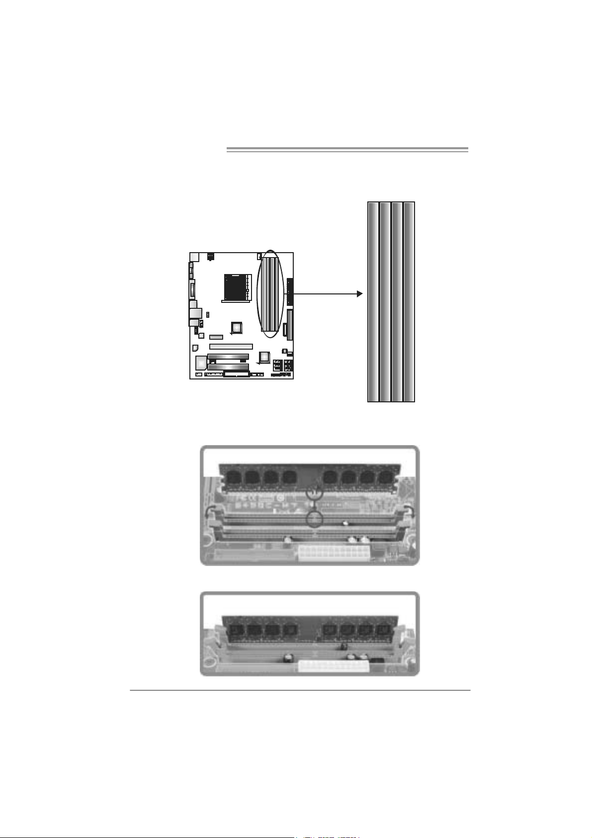
2.3 INSTALLING SYSTEM MEMORY
A. Me mo ry Module s
DIMMB1
DIMMA1
DIMMA2
1. Unlock a DIMM sl ot by pressi ng the retaini ng clips outward. Align a
DIMM on the sl ot such that the notch on the DIMM matches the
break on the Slot.
DIMMB2
2. Insert the DIMM vertically and firml y into the slot until the retaining
chip snap back in place and the DIMM is properl y seated.
8
Page 11
A740G M2+
B. Memory Capacity
DI MM Socket
Location
DIMMA1 256MB/512MB/1GB/2GB
DIMMB1 256MB/512MB/1GB/2GB
DIMMA2 256MB/512MB/1GB/2GB
DIMMB2 256MB/512MB/1GB/2GB
DDR2 Module
To t al Mem o r y
Size
Max is 8 G B.
C. Dual Channel Memory installation
To trigger t he Dual Channel function of t he motherboard, the m emory m odule
must meet the following requiremen t s:
Install memory m odule of the same density in pairs, shown in the following
table.
Du al Channel Status
Enabled O O X X
Enabled X X O O
Enabled O O O O
DIMMA1
DIMMB1
(O means memory installed, X means memory not installed.)
The DRAM bus width of the memory m odule must be the same (x8 or
x16)
DIMMA2
DIMMB2
9
Page 12
Motherboard Manual
2.4 CONNECTORS AND SLOTS
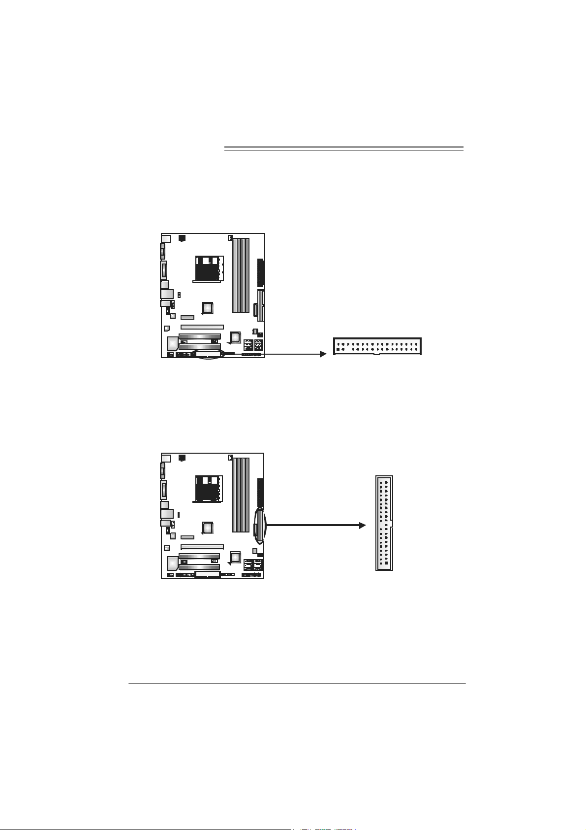
FDD1: Floppy Di sk C onnector
The motherboard provides a st andard floppy disk connector t hat supports 360K,
720K, 1. 2M, 1.44M and 2.88M floppy disk types . This c onnector support s t he
provided f loppy driv e ribbon cable.
234
ID E1: Hard Disk C onne ctor
The motherboard has a 32-bit Enhanced PCI ID E Controller t hat prov ides PI O
Mode 0~4, Bus Master, and U lt ra DMA 33/66/100/133 func t ionality.
The IDE connectors can c onnect a m aster and a s lav e drive, so you can
connec t up t o two hard dis k drives.
133
3940
21
10
Page 13
A740G M2+
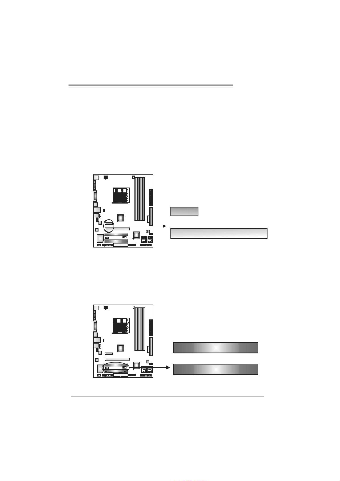
PEX16_1: PCI-Express x16 Slot
- PCI -Ex press 1.0a c ompliant.
- Maximum theoretical realized bandwidth of 4GB/s sim ult aneously per
direct ion, f or an aggregate of 8GB/ s totally.
PEX1_1: PCI-Express x1 Slot
- PCI -Ex press 1.0a c ompliant.
- Dat a transfer bandwidth up to 250MB/s per direct ion; 500MB/s in tot al.
- PCI -Ex press supports a raw bit-rate of 2.5GB/s on t he data pins.
- 2X bandwidth ov er the t radit i onal PCI arc hit ecture.
PEX1_1
PEX16_1
PCI1~PCI2: Periphe ral Component Interconnect Slots
This mot herboard is equipped with 2 standard PCI slots. PC I stands for
Peripheral Com ponent I nt erconnect, and it is a bus standard for expansion
cards . This PCI slot is designated as 32 bits .
PCI1
PCI2
11
Page 14
Motherboard Manual
CHAPTER 3: HEADERS & JUMPERS SETUP
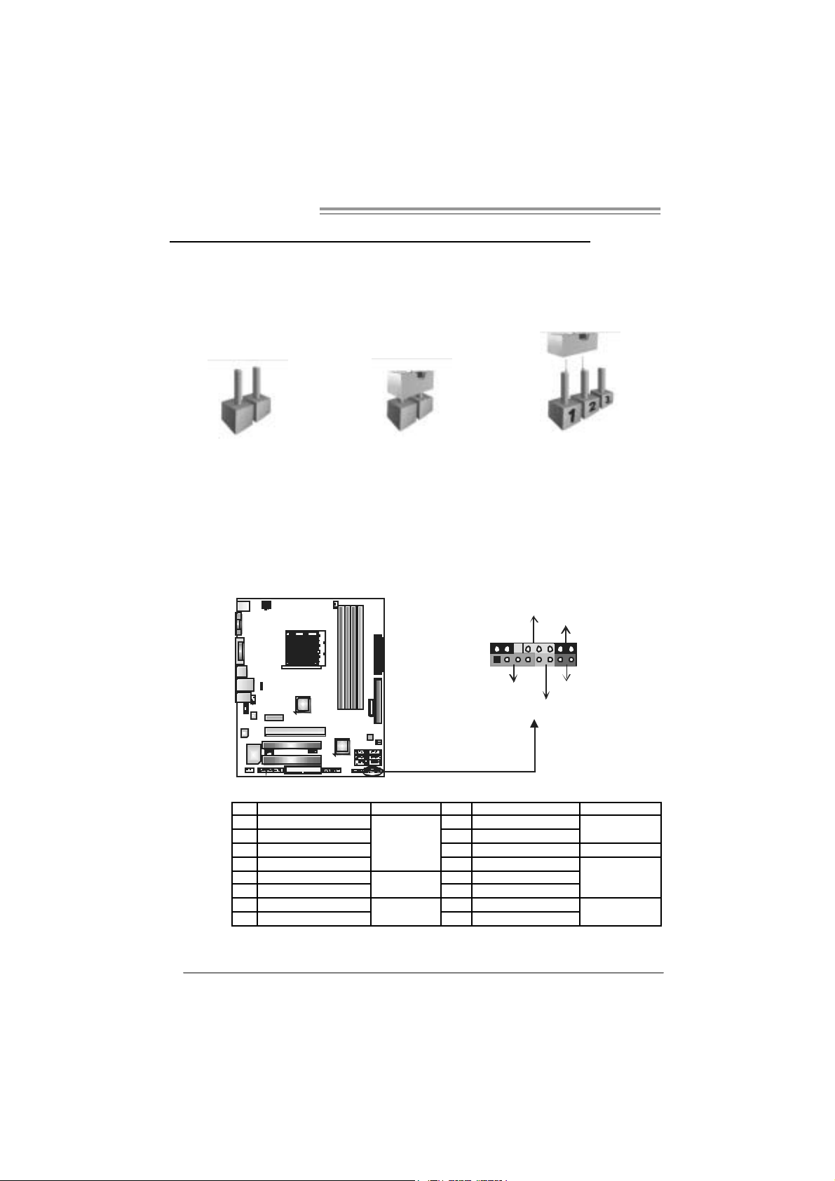
3.1 HOW TO SETUP JUMPERS
The illustration shows how to set up jumpers. When the jumper cap is
placed on pins, the jumper is “close”, if not, that means the jumper is
“open”.
Pin opened Pin closed Pin1-2 closed
3.2 DETAIL SETT INGS
JPANEL1: Front Panel Header
This 16-pin connector includes Power-on, Reset, HDD LED , Power LED, and
speak er connection. It allows user to connec t the PC c ase’s front panel switc h
functions.
PWR_LED
On/Off
-
SPK
++
HLED
16
8
-
+
RST
9
1
12
Pin Assignment Function Pin Assignment Function
1 +5V 9 N/A
2 N/A 10 N/A
3 N/A 11 N/A N/A
4 Speaker
5 HDD LED (+) 13 Power LED (+)
6 HDD LED (-)
7 Ground 15 Power button
8 Reset control
Speaker
Connector
Hard drive
LED
Reset button
12 Power LED (+)
14 Power LED (-)
16 Ground
N/A
Powe r LED
Power-on button
Page 15
A740G M2+
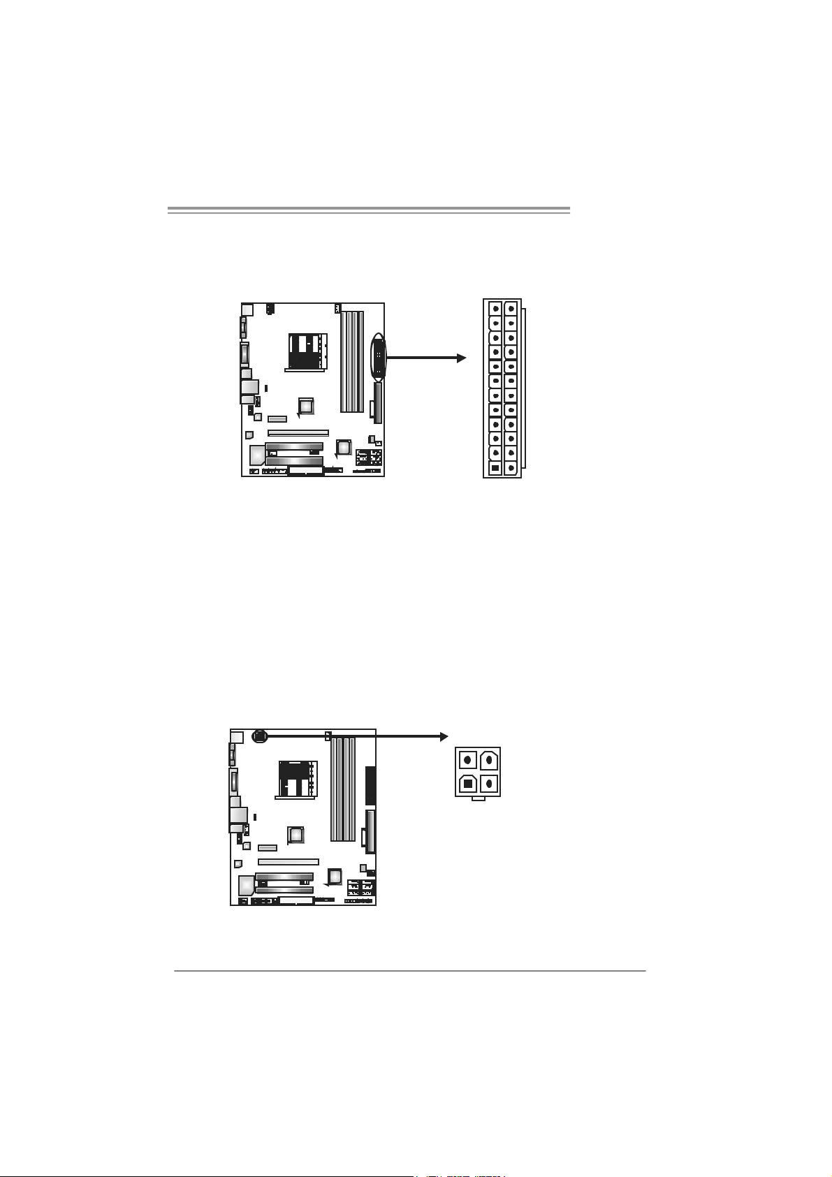
J A TXP W R1 : ATX P o we r S ou rce C onn e cto r
This connector allows user t o connect 24-pin power connector on the ATX
power supply .
12
1
24
13
Pin Assignment Pin Assignment
13 +3.3V 1 +3.3V
14 -12V 2 +3.3V
15 Ground 3 Ground
16 PS_ON 4 +5V
17 Ground 5 Ground
18 Ground 6 +5V
19 Ground 7 Ground
20 NC 8 PW_OK
21 +5V 9 Standby Voltage+5V
22 +5V 10 +12V
23 +5V 11 +12V
24 Ground 12 +3.3V
J A TXP W R2 : ATX P o we r S ou rce C onn e cto r
By c onnecting this connector, it will provide +12V to CPU power circ uit.
34
12
Pin
Assignment
1 +12V
2 +12V
3 Ground
4 Ground
13
Page 16

Motherboard Manual
JUSB2/JUSB3/JUSB4: Headers for USB 2.0 Ports at Front Panel
This header allows us er to c onnect additional USB c able on the PC front panel,
and also can be c onnected wit h internal USB devices, like U SB card reader.
JU SB4
JU SB3 JUSB2
210
19
SATA1~SATA6: Serial ATA Connectors
The motherboard has a PCI to SATA C ont roller wit h 6 channels SATA interf ace,
it satisfies the SATA 2.0 spec and with transfer rate of 3.0Gb/s.
SATA5 SATA6
SATA3 SATA4
SATA1 SATA2
Assignment
Pin
1 +5V (fused)
2 +5V (fused)
3 USB4 USB-
5 USB+
6 USB+
7 Ground
8 Ground
9 NC
10 Key
Pin
Assignment
1 Ground
2 TX+
3 TX-
4 Ground
5 RX6 RX+
7 Ground
14
147
Page 17

A740G M2+
JSP DIF_O UT1: Digi tal Audio-ou t C onne ctor
This connector allows user t o connect the PCI bracket SPD IF output header.
Pin
Assignment
1 +5V
2 SPDIF_OUT
3 Ground
13
JAUDIO F1: Front Panel Audio Heade r
This header allows us er to connect the front audio output cable with the PC f ront
panel. This header allows only HD audio f ront panel c onnector; AC ’97 connector
is not accept able.
Pin Assignment
1 Mic Left in
2 Ground
3 Mic Right in
4 GPIO
10
9
1
2
5 Right line in
6 Jack Sense
7 Front Sense
8 Key
9 Left line in
10 Jack Sense
15
Page 18

Motherboard Manual
JCDIN1: CD-RO M Audio-in Connector
This connector allows user to connect t he audio sourc e from the variaty dev ices,
like CD-R OM, DVD-ROM, PCI sound card, PCI TV turner c ard etc .
JCMOS1: Clear CMOS Header
By plac ing the jum per on pin2-3, it allows user to restore the BI OS safe sett ing
and the CMOS data, please caref ully follow the procedures to av oid damaging
the m otherboard.
※ Clear CMOS Proce dures:
1. R em ove AC power line.
2. Set the jumper to “Pin 2-3 close”.
3. Wai t for five se co n ds.
4. Set the jumper to “Pin 1-2 close”.
5. Power on the AC.
6. R es et your desired pass word or clear the C MOS dat a.
13
Pin
1 Left Channel
1
2 Ground
3 Ground
4 Right Channel
4
13
Pin 1-2 Close:
Normal Operation
(default).
13
Pin 2-3 Close:
Clear CMOS data.
Assignment
Input
Input
16
Page 19

A740G M2+
JPRNT1: Printer Port Connector
This header allows y ou to c onnector printer on the PC.
2
125
Pin Assignment Pin Assignment
1 -Strobe 14 Ground
2 -ALF 15 Data 6
3 Data 0 16 Ground
4 -Error 17 Data 7
5 Data 1 18 Ground
6 -Init 19 -ACK
7 Data 2 20 Ground
8 -Scltin 21 Busy
9 Data 3 22 Ground
10 Ground 23 PE
11 Data 4 24 Ground
12 Ground 25 SCLT
13 Data 5 26 Key
JCO M1 : Serial port Connector
The motherboard has a Serial Port C onnect or for connecting R S-232 Port.
Pin
Assignment
1 Carrier detect
2 Received data
3 Transmitted data
4 Data terminal ready
5 Signal ground
6 Data set ready
7 Request to send
210
19
8 Clear to send
9 Ring indicator
10 NC
17
Page 20

Motherboard Manual
J U SB V1 / J US B V 2: Po we r S o ur ce Hea de rs f o r USB P o rts
Pin 1-2 Close :
JU SBV1: +5V f or USB ports at JUSB1/JUSBLAN1.
JU SBV2: +5V f or USB ports at f ront panel (JUSB2/JU SB3/JUSB4).
Pin 2-3 Close :
JU SBV1: +5V STB f or USB ports at JU SB1/JU SBLAN1.
JU SBV2: +5V STB f or USB ports at front panel (JU SB2/JU SB3/JUSB4).
JUSBV1
1
3
13
JUSBV2
1
3
1
3
13
Pin 1-2 close
13
Pin 2-3 close
18
Page 21

A740G M2+
CHAPTER 4: RAID FUNCTIONS
4.1 OPERATION SYSTEM
z Supports Windows XP Hom e/Prof essional Edition, and Windows Vista.
4.2 RAID ARRAYS
RAI D supports the following types of R AID arrays :
RAID 0: RAID 0 defines a disk striping scheme that improves disk read and write times for
RAID 1: RAID 1 defi nes techniques for mirroring data.
RAID 1+0: RAID 1+0 combines the techniques used in RAID 0 and RAID 1.
many applications.
4.3 HOW RAID WORKS
RAID 0:
The controller “stripes” d ata across mul tiple drives in a RAID 0 array system. It breaks
up a large file into smaller blocks and performs disk reads and writes across multiple
drives in parallel. The size of each block is determined by the s tripe size p arameter,
which you set during the creation of the RAID set based on the system environment.
This technique reduces overall disk acces s time and o ffers high bandwidth.
Fea tures and Be nefits
- Drives: Minimum 1, and maximum is up to 6 or 8. Depending on t he
platform.
- Uses: I ntended for non-c rit ical data requiring high data throughput , or any
environm ent that does not require f ault toleranc e.
- Benefits: prov ides increased dat a throughput, especially f or large files.
No c apacity loss penalty f or parity.
- Drawbacks: Does not deliver any fault toleranc e. If any drive in t he array
fails , all dat a is lost.
- Faul t Tolerance: No.
Bl ock 1
Block 3
Block 5
Block 2
Block 4
Block 6
19
Page 22

Motherboard Manual
RAID 1:
Every read and write is act ual ly carried out in p arallel acro ss 2 disk drives i n a RAID 1
array system. The mirrored (backup) copy of the data can reside on the same disk or on
a second redundant drive in t he array . RAID 1 provides a hot -st andby copy of data if
the active volume or drive i s co rrupted or b ecomes un avai lable because of a hardw are
failure.
RAID techniques can be applied for high-availability solutions, or as a form o f
automatic backup that eliminates tedious manual backups to more expensive and less
reliable media.
Fea tures and Be nefits
- Drives: Minimum 2, and maximum is 2.
- Uses: RAID 1 is ideal for small databas es or any other applicat ion that
requires f ault tolerance and minimal ca paci t y.
- Benefits: Prov ides 100% dat a redundancy. Should one driv e fail, the
controller switches to the o ther drive.
- Drawbacks: Requires 2 drives for t he storage spac e of one drive.
Perform anc e is impaired during driv e rebuilds.
- Faul t Tolerance: Yes.
20
Block 1
Block 2
Block 3
Block 1
Block 2
Block 3
Page 23

A740G M2+
RAID 1+0:
RAID 1 drives can be stripped using RAID 0 techniques. Resulting in a RAID 1+0
solution for improved resiliency, performance and rebuild performance.
Fea tures and Be nefits
- Drives: Minim um 4, and max imum is 6 or 8, depending on t he platf orm.
- Benefits: Optim izes for bot h fault toleranc e and perform anc e, allowing f or
autom at ic redundancy. May be sim ultaneously us ed with other RAID
levels in an array, and allows for s pare disks.
- Drawbacks: Requires twice t he available dis k s pac e for data redundancy,
the same as RAID level 1.
- Faul t Tolerance: Yes.
Block 1
Block 3
Block 5
Block 1
Block 3
Block 5
Block 2
Block 4
Block 6
Block 2
Block 4
Block 6
21
Page 24

Motherboard Manual
CHAPTER 5: USEFUL HELP
5.1 DRIVER INSTALLA TION NOTE
After you installed your operating system, please insert the Fully Setup
Driver CD into your opti cal drive and install the driver for better system
performance.
You will see the following window after you insert the CD
The setup gu ide will auto detec t yo ur motherboard an d opera ting system.
Note:
If this window didn’t show up after you ins ert the Driver CD, please use file browser to
l ocate and e xecu te t h e fi l e SETU P.E XE un der yo ur o pti c al dr ive .
A. Driver Installation
To install the dri ver, pl ease click on the Dri ver icon. The setup guide will
list the compatible driver for your motherboard and operating system.
Click on each devi ce driver to launch the installation program.
B. Software Installation
To install the software, please click on the Software icon. The setup guide
will list the software available for your system, click on each software title
to la unch th e ins t a l lat io n pr ogr a m.
C. Manual
Aside from the paperback manual, we also provi de manual in the Driver
CD. Click on the M anual icon to browse for available manual.
Note:
You will need Acrob at Read er to open the man ual file. Please downloa d the la te s t version
of Acrobat Reader software from
http://www.adobe.com/products /a crobat/readstep2.html
22
Page 25

A740G M2+
5.2 SOFTWARE
Ins talling Software
1. Insert the Setup CD to the opti cal dri ve. The drivers i nstallation program
woul d appear if the Autor un fu nc t ion has bee n enab l ed.
2. Select Software Installation, and then click on the respecti ve software
title.
3. Follow the on-screen instructions to com plete the installation.
Lau nchi n g S o f t ware
After the installation process, you will see the software icon “eHOT Line” /
“BIOS Update” appears on the desktop. Double-click the i con to launch the
utili ty.
eHot-Line (Optional)
eHot-Li ne is a convenient utility that helps you to contact with our
Tech-Support system. Thi s utility will collect th e system informati on which is
useful for analyzing the problem you may have encountered, and then send
these i nformation to our tech-support department to help you fi x the problem.
Before you use this utility, plea se set Outlook Express as y our default e-ma il client application program.
represen ts important
*
i n for m at i on t hat you
must provide. Without
this information, you may
n ot be abl e to se nd ou t
the mai l.
This bl ock will show
the in fo rmation whic h
would b e collecte d in
the m ai l.
Des c r i be c ond i tion
*
of your system.
Send t h e m a il ou t .
Save thes e i nfor mat ion to a .txt fil e
Exit this dialog.
Select your area or
*
the ar ea c lose t o you.
Provid e th e e -mai l
addre ss th at you would
like to send the copy to.
Provide the na me of
*
the memory module
manu factur er.
Provid e th e n ame of
the po we r sup pl y
man ufac t u rer an d the
model no.
23
Page 26

Motherboard Manual
After filli ng up t his inf orma tio n, cli c k “Send”
to send the mail out. A warning dialog would
appear asking for your confirmation; click
“Send” to confirm or “Do Not Se n d” to cancel.
If you want to sa ve this informatio n to a .txt file, cli ck “Save As…” and then you
will see a saving dialog appears asking you to enter file nam e.
Enter the f ile name an d th en click
“Save ”. Your system information
will be saved to a .txt file .
24
Open the saved .txt file, you will see
your system informati on including
motherboard/BIOS/CPU/vi deo/
dev ice/OS infor m at ion. This
informati on is al so concluded in the
sent mail.
We will not share customer’s data with any other third parties,
so please feel free to provide your system i nformati on whil e usi ng
eHot-Line service.
If you are not using Outlook Express as your default e-mail client
application, you may need to save the system in formation to a .txt file
and send the file to our tech support with other e-mail appli cation.
Go to the following web
http://www.biosta r.com.tw/app /en-us/about/contact.php for getting
our contact i nformati on.
Page 27

A740G M2+
BI OS Update
BIOS Update is a convenient utili ty which allows you to update your
motherboard BIOS under Wi ndows system.
AWARD BIOS AMI BIOS
Clear CMOS function
(Only for AWARD BIOS)
Show current BIOS inform ation
Save current BIOS
to a .bin file
Updat e BIOS
with a BIOS file
<Backup BIOS>
Once click on this button, the saving
dialog will sho w. Choose the
position to save file and enter file
nam e. (We recommend that the file
nam e should be English/number
and no longer than 7 characters.)
Th en click Save.
After the savi ng process, fi nish
dialog will sho w. Click on OK to
complete the BIOS Backup
procedure.
25
Page 28

Motherboard Manual
<Update BIOS>
Before doing thi s, please download the proper BIOS fi le from the website.
For AWARD BIOS, update BIOS procedure
should be run with Clear CMOS function, so
plea se check on Clear CM OS first.
Then click Update BI OS button, a
dialog will show for asking you bac k up
current BIOS. Click Yes for BIOS
back up and refer t o the Backup BIOS
procedure; or clic k No to ski p this
procedure.
Af t er the BI OS Back up procedure, the
open dialog will show f or request ing the
BIOS f ile whic h is going t o be updat ed.
Please c hoose t he proper BIOS f ile for
updating, then click on Open.
The utility will update BI OS wit h the
proper BIOS file, and this process may
tak e minut es. Pleas e do not open any
other applic ations during this process.
Af t er the BI OS Updat e process, click on
OK to restart the system.
While t he sy stem boots up and t he full screen logo shows, press <Delete>
key to enter BIOS setup.
In the BIOS setup, use the Lo a d O ptim ize d Def au lt s function and t hen Save and
Exit Setup to ex it BIOS set up. BIOS Update is c ompleted.
All the i nfor mati on and content above about the sof tware are subject to be changed
without notice. For better perfor mance, the software is being continuously updated.
The information and pictures described above are for your refer ence onl y. The actual
i nfor m ati o n and s etti ngs on bo ar d ma y be s l i g htl y di ffer e nt f r o m thi s ma nual .
26
Page 29

5.3 EXT RA INFORMATION
CPU Overhe ated
If the system shutdown automatically after power on system for
seconds, that means the CPU protecti on function has been activated.
When the CPU is over heated, the motherboard will shutdown
automatically to avoid a damage of the CPU, and the system may not
power on again.
In this case, please double check:
1. The CPU cooler surface is placed evenly with the CPU surface.
2. CPU fan is rotated normally.
3. CPU fan speed is fulfilling with the CPU speed.
After confirmed, pl ease follow steps below to relief the CPU protection
function.
1. Remove the power cord from power supply for seconds.
2. Wait for seconds.
3. Plug in the power cord and boot up the system.
Or you can:
1. Clear the CMOS data.
(See “Close CMOS Header: JCMOS1” section)
2. Wait for seconds.
3. P ower on th e sy stem again.
A740G M2+
27
Page 30

Motherboard Manual
BIO-Flasher
BIO-F las her is a BIOS flas hing utility prov iding you an easy and simple way to
update y our BIOS v ia USB pen driv e or floppy disk.
The B IO- Fl a she r is b u i l t i n th e BI O S ch i p . To ent e r th e ut i l i ty, press <F12>
during the Power-On Self Tests (POST) procedure while booting up.
Updating BIOS wi th BIO-Flasher
1. Go to the websi te to download the la test BIOS file for the motherboard .
2. Then, s av e the BI OS file int o a USB pen drive or a floppy disk.
3. Insert the USB pen drive or t he floppy disk that contains the BIOS f ile to t he
USB port or t he floppy disk drive.
4. Power on or res et t he computer and t hen
press <F 12> during the POST process.
A select dialog as the pic t ure on t he right
appears.
Select the dev ic e cont ains the BIOS f ile and
press <E nter> to enter the utility.
28
5. The utility will show the BIOS
files and their res pective
inf orm ation. Select the proper
BIOS f ile and press <Enter>
then <Y> to perf orm t he BIOS
update proc ess.
6. After the updat e proces s, the ut ility will ask y ou to reboot the sy s t em.
Press <Y > to proc eed. BIOS update c om pletes.
z This ut ility on ly allows storage dev ic e with F AT32/16 forma t a nd single
partition.
z S huttin g down or rese tting the system while upd ating the B IOS will lead to
system boot failure.
Page 31

5.4 TROUBLESHOOTING
e
Probable Solution
1. N o power to the system at all
Power light don’t illuminat e, f an
inside power s upply does not turn
on.
2. I ndic at or light on k eyboard does
not t urn on.
Sys t em inoperat iv e. Key board lights
are on, power indic at or lights are lit,
and hard driv e is s pinning.
Sys t em does not boot from hard disk
drive, can be boot ed from optical drive.
Sys t em only boots from optical drive.
Hard disk can be read and applicat ions
can be used but booting from hard dis k
is imposs ible.
Screen m essage say s “Invalid
Conf igurat ion” or “CMOS Failure.”
Cannot boot sys t em aft er inst alling
sec ond hard drive.
A740G M2+
1. Make s ure power c able is
sec urely plugged in.
2. Replace cable.
3. Contact technical support.
Us ing even pres s ure on bot h ends of
the DIMM, press down firm ly until the
module s naps int o place.
1. C hec k cable running from disk t o
disk controller board. Make sure
both ends are s ec urely plugged
i n; c hec k t he dr iv e t y pe in t he
standard CMOS se tup.
2. Bac k ing up the hard driv e is
ext rem ely im port ant. All hard
disk s are c apable of break ing
down at any t ime.
1. Bac k up data and applic at ions
files.
2. R eformat t he hard drive.
Re-ins t all applicat ions and dat a
using backup disks.
Rev iew sys t em’s equipment. Make s ur
correc t inf ormation is in setup.
1. Set m ast er/slave jumpers
correctly.
2. R un SETUP program and select
correc t driv e ty pes. Call t he drive
manufacturers for co mpatibilit y
with other drives.
29
Page 32

Motherboard Manual
h
APPENDENCIES: SPEC IN O THER LANGUAGE
GERMAN
S p e z i f ik a t io n e n
Sockel AM2+ / AM2
CPU
FSB
Chipsatz
Super E/A
Arbeitsspei c
er
Grafik I nt egrierter AMD 740G-C hips atz
IDE Integrierter IDE-Controller
SA TA I nt e gr i ert er S eri al ATA - Co ntr o ll er
LA N R ealt ek RTL 8101E
HD
Audio-Unters
tützung
AM D Athl on 64 / A t hlon 64 FX / Alt hlon 64
X2 / Sempron / Phenom Prozessoren
Unterstützt HyperTransport 2.0 mit einer
Bandbreit e von bis z u 2.0 GT/s
AM D 74 0G
AM D S B700
ITE8718F
Bi etet die häufig verwendeten alten Super
E/A-Funktionen.
DDR2 DIMM-Steckplätze x 4
M ax. 8GB A rbeit ss peiche r
Jeder DIMM unterstützt
256/512MB/1GB/2GB DDR 2.
ALC662
PCI Express x16 St eckplatz x1
PCI Express x1 Steckplatz x1 Steckplätze
PCI-Steckplatz x2
30
Die A MD 64-Arc hitektur unterstützt eine 32-Bit- und
64-Bit-Datenverarbeitung
Unterstützt Hyper Transport 2.0 und Cool’n’Quiet
Low Pin Count-Schnittstelle
Umgebungs kontrolle,
Hardw are-Überwac hung
"Smart Guardi an"-Funktion von ITE
Dual-Kanal DDR2 Speicherm odul
Unt erstützt DDR2 533 / 667 / 800
Unt erstützt DDR2 1066 (for AM2+ CPU only)
registrierte DIMMs. ECC DIMMs werden nicht
unterstützt.
Max. 512MB gemeinsam benutzter Videospeicher
Unterstützt HDCP
Ultra DMA 33 / 66 / 100 / 133 Bus Master-Modus
Unterstützt PIO-Modus 0~4,
Datentransferrate bis zu 3 Gb/s
Konform mit der SATA-Spezifikation Vers ion 2.0.
10 / 100 Mb/s Auto-Negotiation
Halb-/ Vollduplex-Funktion
5.1-Kanal-Audioausgabe
Unterstützt High-Definition Audio
Page 33

Onboard-Ans
chluss
A740G M2+
S p e z i f ik a t io n e n
Diskettenlaufwerkanschluss x1 Jeder Anschluss unterstützt 2 Diskettenlaufwerke
IDE-Anschluss x1 Jeder A nsc hluss unterstützt 2 IDE-Laufwerke
SATA-Anschluss x6 Jeder Anschluss unterstützt 1 SATA-Laufwerk
Fronttafelanschluss x1 Unterstützt die Fronttafelfunktionen
Front-Audioanschluss x1 Unterstützt die Fronttafel-Audioanschlussfunktion
CD-IN-Anschluss x1 Unterstützt die CD Audio-In-Funktion
S/PDIF- A usgangsanschluss x1 Unt erstützt die digi tale Audioausgabefunkt ion
CPU-Lüfter-Sockel x1
System-Lüfter-Sockel x1 System-Lüfter-Stromversorgungsanschluss
"CMOS löschen"-Sockel x1
US B-Anschl uss x3
Stromanschluss (24-polig) x1
Stromanschluss (4-polig) x1
Druckeranschluss Anschluss x1 Jeder Anschluss unterstützt 1 Druckeranschluss
Seriell er A nschluss x1
CPU-Lüfterstromversorgungsanschluss (mit Smart
Fan-Funktion)
Jeder Anschluss unterstützt 2
Fronttafel-USB-Anschlüsse
Rückseiten-E
/A
Platinengröß
e
Sonderfunkti
onen
OS-Unterstü
tzung
PS/2-Tastatur x1
PS/2-Maus x1
VGA-Anschluss x1
LAN-Anschl uss x1
US B-Anschl uss x4
Audi oanschluss x3
DV I-A nschluss x1
215 mm (B) X 244 mm (L)
Unterstützt RAID 0 / 1 / 1+0
Windows XP / VISTA
Biostar behält sich das Recht vor, ohne Ankündigung
die Unterstützung für ein Betriebssystem
hinz uzufügen oder z u entfernen.
31
Page 34

Motherboard Manual
FRANCE
S ocket AM 2+ / AM 2
UC
Bus frontal
Chipset
Super E/S
Mémoire
princ ipale
Graphiques Int egré dans la chi pset AMD 740G
IDE C ontrôleur IDE intégré
SA TA
LA N Realt ek RTL 8101E
Prise en
charge
audio HD
Connecteur
embarqué
32
Processeurs AMD Athlon 64 / Athlon 64 FX
/ Althlon 64 X2 / Sempron / Phenom
Prend en charge Hyper Transport 2. 0
jusqu'à une bande passante de 2.0 GT/s
AM D 74 0G
AM D S B700
ITE 8718F
Four nit la fonctionnalit é de Super E/S
patrimoniales la plus utilisée.
Fentes DDR2 DIMM x 4
Capacité mémoire maximale de 8 Go
Chaque DIMM prend en charge des DDR2
de 256/512 M o et 1Go/2Go
Cont r ôl eur Se rial ATA intégré
ALC662
Fente PCI Express x16 x1
Fente PCI Express x1 x1 Fentes
Fente PCI x2
Connecteur de disquette x1
Connecteur IDE x1
Connec t eur SATA x6
SPEC
L'architectur e AMD 64 permet le calcul 32 et 64 bits
Prend en charge Hyper Transport 2.0 et Cool’n’Quiet
Interface à faible compte de broches
Initiatives de contrôle envir onnementales,
Moniteur de matériel
Fonction "Gardien intelligent" de l'ITE
Module de mémoire DDR2 à mode à double voie
Prend en char ge la DDR2 533 / 667 / 800
Prend en charge la DDR2 1066 (for AM2+ CPU onl y)
Les DIMM à registres et DIMM avec code correcteurs
d'erreurs ne sont pas prises en charge
Mémoi re vidéo partagée maximale de 512 Mo
Prise en charge HDCP
Mode principale de Bus Ultra DMA 33 / 66 / 100 / 133
Prend en charge le mode PIO 0~4,
Taux de transfert jusqu'à 3 Go/s.
Conforme à la spécification SATA Version 2.0
10 / 100 Mb/s négociation automati que
Half / Full duplex capability
Sortie audio à 5. 1 voies
Prise en charge de l'audio haute définition
Chaque connector prend en charge 2 lecteurs de
dis quettes
Chaque c onnecteur prend en charge 2 périphériques
IDE
Chaque c onnecteur prend en charge 1 périphérique
SA TA
Page 35

Connecteur du panneau avant x1 Prend en charge les équi pements du panneau avant
Connecteur Audio du panneau avant x1 Prend en c harge la fonction audio du panneau avant
Connecteur d'entrée CD x1 Prend en charge la fonction d'entrée audio de CD
Connecteur de sortie S/PDIF x1 Prend en charge la fonction de sortie audio numérique
Embase de ventilateur UC x1
Embase de ventilat eur système x1 Alimentation élect rique du vent ilateur système
Embase d'effacem ent CMOS x1
Connecteur USB x3
Connecteur d'alimentation x1
(24 broc hes)
Connecteur d'alimentation x1
(4 broches)
Connecteur de Port d'imprimante x1
Connecteur de Port série x1
Clavier PS/2 x1
Souris PS/2 x1
E/S du
panneau
arrière
Dim ension
s de la
carte
Fonctionnal
ités
spéciales
Support SE Windows XP / VISTA
Port VGA x1
Port LAN x1
Port USB x4
Fiche audio x3
Port DVI x1
215 mm (l) X 244 mm (H)
Prise en c harge RAI D 0 / 1 / 1+ 0
A740G M2+
SPEC
Alimentation électrique du ventilateur UC (avec
fonction de ventilateur intelligent)
Chaque c onnecteur prend en charge 2 ports USB de
panneau avant
Chaque connector prend en charge 1 Port
d'imprimante
Bi ostar se r éserve le droit d'ajout er ou de s upprimer le
support de SE avec ou s ans préavis.
33
Page 36

Motherboard Manual
/
p
ITALIAN
Socket AM2+ / AM2
CPU
FSB
Chipset
Super I/O
Memoria
princi pale
Grafi c a Integrata nel Chipset AMD 740G
IDE Controller IDE integrato
SATA Controller Serial ATA integrato
LA N Realt ek RTL 8101E
Suppor to
audio HD
Connettori
su scheda
Processori AMD Athlon 64
/ Alt hlon 64 X2 / Sempron / Phenom
Suppor to di Hy perTra nsport 2.0 fi no a
2.0 GT/s di larg hezza di banda
AM D 74 0G
AM D S B700
ITE 8718F
Fornisce le funzionalità legacy Super
I/O usate più c om u nemente.
Al loggi DIMM DDR 2 x 4
Capacità massima della memoria 8GB
Cias cun DIMM s upporta DDR 2
256 /51 2MB e 1GB/2GB
AL C662
Al loggio PC I Expres s x1 6 x1
Al loggio PC I Expres s x1 x1 Alloggi
Alloggio PCI x2
Connettore flo ppy x1 Ci as cun conn ett ore s upport a 2 uni tà Flopp y
Connettore IDE x1 Ciasc un conn ett ore s up porta 2 unità IDE
Connettore SA TA x6 C iascun conn ett or e s up porta 1 unità S ATA
Connettore pannello frontale x1 Supporta i servizi del pannello frontale
A t h l o n 6 4 F X
SPECIFICA
L’architettura AMD 64 abilita l a com
e 64 bit
Suppor to di Hyper Tra ns port 2.0 e Cool’ n’Q uiet
Interfaccia LPC (Low Pin Count)
Funzioni di controllo dell’ambiente:
Monitoraggio hardware
Funz ione "Sm art Guardi an" di I TE
Modulo di memor ia DDR2 a c anal e doppi o
Supporto di DDR2 533 / 667 / 800
Supporto di DDR2 1066 (for AM2+ CPU only)
DIMM registrati e DIMM ECC non sono supportati
La memoria video condivisa massima è di 512 MB
Suppor to HDCP
Modalit à B us M as t er Ult ra DMA 33 / 66 / 10 0 /
133
Suppor to modalità PI O Mode 0- 4
Velocit à di t ras ferim ento dei dati fi no a 3 Gb/s.
Compatibile specifiche SATA Versione 2.0.
Negoziazi one automatic a 10 / 10 0 Mb /s
Capacità Half / Full Duplex
Uscita audio 5.1 ca nali
Suppor to au dio High- Defi niti on (HD)
utazione 32
34
Page 37

I/O
pannello
posteriore
Dim ens ion
i scheda
Caratterist
iche
speciali
Sistemi
operativi
supportati
A740G M2+
SPECIFICA
Connettore audio frontale x1 Supporta la funzione audi o pannello frontale
Connettore CD-in x1 S uppor ta la fu nz ione i np ut au dio C D
Connettore outp ut SPDIF x1 Supporta la fu nzione d’outp ut a udio di gitale
Collettore ventolina CPU x1
Collettore ventolina sistema x1 Alimentazione ventolina di sistema
Collettore cancellazione CMOS x1
Connettore USB x3
Connettore alimentazione x1
(24 pin)
Connettore alimentazione x1
(4 pin)
Connettore Port a st am pa nte x1 Ciascun conn et t ore s up porta 1 P orta s tam pant e
Connettore Porta seriale x1
Ta s t ie r a P S /2 x 1
Mouse PS/2 x1
Porta VGA x1
Porta LAN x1
Porta USB x4
Connettore au dio x3
Porta DVI x1
21 5 mm (largh ezza) x 244 m m
(altezza)
Supporto RA ID 0 / 1 / 1+0
Windows XP / VISTA
Alimentazione ventolina C PU (c on f unz io ne S m art
Fan)
Ciascun connettore supporta 2 porte USB
pannello frontale
Biostar si riserva il diritto di aggiungere o
rimuovere il supporto di qualsiasi sistema
operativo se nza pre avviso.
35
Page 38

Motherboard Manual
SPANISH
Conect or AM 2+ / AM 2
CPU
FSB
Conjunto
de chips
Súper E/S
Memoria
princ ipal
Gráficos
IDE Controlador IDE integrado
SATA Controlador ATA Serie Integrado
Red Local Realtek RTL 8101E
Soporte de
sonido HD
Conectores
en placa
Procesadores AM D At hlon 64 / Athlon 64
FX / Athlon 64 X2 / Sempron / Phenom
Admite HyperTransport 2. 0 con un anc ho
de banda de hasta 2.0 GT/s
AM D 74 0G
AM D S B700
ITE 8718F
Le ofrece las funcionalidades heredadas
de us o más común Súper E/S.
Ranuras DIMM DDR2 x 4
Capacidad máxima de memoria de 8GB
Cada DIMM admite DDR de 256/512MB y
1GB/2GB
Int egrados en el conjunt o de chi ps AMD
740G
ALC662
Ranura PCI Express x16 X1
Ranura PCI Express x1 X1 Ranuras
Ranura PCI X2
Conect or disco flexible X1 Cada conector soporta 2 unidades de disco flexible
Conector IDE X1 Cada conector soporta 2 dispositivos IDE
Conector SATA X6 Cada conector soporta 1 dispositivos SATA
Especificación
La arquitectura AMD 64 permite el procesado de 32 y
64 bits
Soporta las tecnologías Hyper Transport 2.0 y
Cool’n’Quiet
Interfaz de cuenta Low Pin
Iniciativas de control de entorno,
Monitor hardware
Función "Guardia inteligente" de ITE
Módul o de memoria DDR 2 de canal Doble
Admite DDR2 de 533 / 667 / 800
Admite DDR2 de 1066 (for AM2+ CPU onl y)
No admite DIMM registrados o DIMM compatibles con
ECC
Memor ia máxima de vídeo c ompartida de 512 MB
Admite HDCP
Modo bus maestro Ultra DMA 33 / 66 / 100 / 133
Soporte los Modos PIO 0~4,
Tasas de transferencia de hasta 3 Gb/s.
Compatible con la versión SATA 2. 0.
Negociación de 10 / 100 Mb/s
Funciones Hal f / Full dúplex
Salida de sonido de 5.1 canales
Soporte de sonido Alta Definición
36
Page 39

Panel
trasero de
E/S
Ta m año d e
la placa
Funciones
especiales
Soporte de
sistema
operativo
A740G M2+
Especificación
Conector de panel frontal X1 Soporta instalaciones en el panel frontal
Conector de s oni do frontal X1 Soporta funciones de soni do en el panel front al
Conec tor de entrada de CD X1 Soporta función de entrada de s onido de CD
Conect or de s alida S/PDIF X 1 Soporta func ión de sal ida de s onido digital
Cabecera de vent ilador de CPU X1 Fuent e de alimentación de ventilador de CPU (con
func ión S mart Fa n)
Cabecera de vent ilador de s istema X 1 Fuent e de alimentación de vent ilador de s istema
Cabecera de borrado de CMOS X 1
Conector USB X3 Cada conector soporta 2 puertos USB frontales
Conector de alimentación X1
(24 pat illas)
Conector de alimentación X1
(4 patillas)
Conect or Puerto de impresora X 1 Cada c onector soporta 1 Puerto de impres ora
Conector Puerto serie X1
Te c l ado PS / 2 X 1
Ratón PS/2 X1
Puerto VGA X1
Puerto de red local X 1
Puerto USB X4
Conector de sonido X3
Puerto DVI X1
215 mm. (A) X 244 Mm. (H)
Admite RAID 0 / 1 / 1+0
Windows XP / VISTA
Biostar se reserva el derec ho de añadir o retirar el
soporte de cualquier SO con o sin aviso previo.
37
Page 40

Motherboard Manual
4
PORTUGUESE
S ocket AM 2+ / AM 2
CPU
FSB
Chipset
Especificaç
ão Super
I/O
Memória
princ ipal
Placa
gráfic a
IDE Controlador IDE integrado
SATA Controlador Serial ATA i nt egrado
LA N Realt ek RTL 8101E
Suporte
para áudio
de alta
definição
Conectores
na placa
38
Processadores AMD Athlon 64 / At hl on 6
FX / Althlon 64 X2 / Sempron / Phenom
Suporta a tec nologia HyperTrans port 2. 0
com uma largura de banda até 2.0 GT/s
AM D 74 0G
AM D S B700
ITE 8718F
Proporciona as funcionalidades mais
utilizadas em termos da especi ficação
Super I/O.
Ranhuras DIMM DDR2 x 4
Capacidade máxima de memória: 8 GB
Cada módulo DI MM suporta uma
memória DDR2 de 256/512 M B & 1 GB/2
GB
Int egrada no chipset AM D 740G
ALC662
Ranhura PCI Express x16 x1
Ranhura PCI Express x1 x1 Ranhuras
Ranhura PCI x2
Conect or da unidade de disquetes x1 C ada conector suporta 2 unidades de disquetes
Conector IDE x1 Cada conector suporta 2 dispositivos IDE
Conector SATA x6 Cada conector suporta 1 dispositivo SATA
Conector do painel frontal x1 Par a suporte de várias funções no painel frontal
ESPECIFICAÇÕES
A arquitectura AMD 64 perm ite uma comput ação de
32 e 64 bits
Suporta as tecnologias Hyper Transport 2.0 e
Cool’n’Quiet
Int erface LPC (Low Pin Count).
Iniciativas para controlo do ambiente
Monitorização do hardware
Função "Smart Guardian" da ITE
Módulo de memória DDR2 de canal duplo
Suporta módul os DDR2 533 / 667 / 800
Suporta módul os DDR2 1066 (for AM2+ CPU only)
Os módulos DIMM registados e os DIMM ECC não são
suportados
Memór ia de vídeo máxima partilhada: 512 MB
Suporta as funções HDCP
Modo Bus master Ultra DMA 33 / 66 / 100 / 133
Suporta o m odo PIO 0~ 4,
Velocidades de transmissão de dados até 3 Gb/s.
Compatibilidade com a especificação SATA versão 2.0.
Auto negociação de 10 / 100 Mb/s
Capacidade semi/full-duplex
Saída de áudio de 5. 1 canais
Suporta a especificação High-Definit ion A udio
Page 41

Entradas/S
aídas no
painel
traseiro
Tamanho
da placa
Característi
cas
especiais
Sistemas
operativos
suportados
A740G M2+
ESPECIFICAÇÕES
Conec tor de áudio frontal x1 Suporta a funç ão de áudio no painel frontal
Conec tor para entrada de CDs x1 Suporta a entrada de áudio a partir de CDs
Conec tor de s aída S/PDIF x1 Suporta a saída de áudio digital
Conector da ventoinha da CPU x1
Conector da ventoinha do sistema x1 A lim entação da ventoi nha do sistema
Conector para limpeza do CMOS x1
Conector USB x3 Cada conector suporta 2 portas USB no painel frontal
Conector de alimentação x1
(24 pinos)
Conector de alimentação x1
(4 pinos)
Conector da para impressora x1 C ada conector suporta 1 Porta para impressora
Conector da Porta série x1
Te c l ado PS / 2 x 1
Rato PS/2 x1
Porta VGA x1
Porta LAN x1
Porta USB x4
Tomada de áudio x3
Porta DVI x1
215 mm (L) X 244 mm (A)
Suporta as funções RAID 0 / 1 / 1+0
Windows XP / VISTA
Aliment ação da vent oi nha da CPU (c om a função
Smart Fan)
A Biostar reserva-se o direito de adicionar ou remover
suporte para qualquer sistema operativo com ou sem
aviso prévio.
39
Page 42

Motherboard Manual
POLISH
SPEC
S ocket AM 2+ / AM 2
Procesor
FSB
Chipset
Pamięć
główna
Super I/O
Grafika Zintegrowana w chipsecie AMD 740G
I DE Z i nt e gro w an y k o nt r ol e r I D E
SATA Zintegrowany kontrol er Serial A TA
LA N Realt ek RTL 8101E
Obsługa
audio HD
Złącz a
wbudowan
e Złącz e SA TA x6 K ażde złącze obsługuje 1 urządzenie SA TA
AM D Athl on 64 / A thlon 64 FX / A lthl on 64
X2 / Sempron / Phenom Proces ory
Obsługa HyperTrans port 2.0 o szerokości
pasma do 2. 0 GT/s
AM D 74 0G
AM D S B700
Gniaz da DDR2 DIMM x 4
Maks. wielkość pa mi ęci 8GB
Każde gniaz do DIMM obsługuje m oduły
256/512MB oraz 1GB /2GB DDR2
ITE 8718F
Zapewnia najbardziej powszechne
funkc je S uper I/O.
ALC662
Gniazdo PCI Express x16 x1
Gniazdo PCI Express x1 x1 Gni az da
Gniazdo PCI x2
Złącz e napędu dyskietek x1 K ażde z łącz e o bsługuje 2 napędy dyskiet ek
Złącz e IDE x1 K ażde z łącz e obsługuje 2 urządzenia I DE
Architektura AMD 64 um ożliw ia przetwarzanie 32 i 64
bit owe
Obsługa Hyper Transport 2.0 oraz Cool’n’Q uiet
Moduł pamięci DDR2 z trybem podwójnego kanału
Obsługa DDR 2 533 / 667 / 800
Obsługa DDR 2 1066 (for AM2+ CPU only)
Brak obsługi Registered DIMM oraz ECC DIMM
Int erfejs Low Pin Count
Funkcje kontroli warunków pracy,
Monitor H/W
Funkcja ITE "Smart Guardian"
Maks. wielkość ws pó łdzielonej pamięci video wynosi
512 MB
Obsługa HDC P
Ultra DMA 33 / 66 / 100 / 133 Tr yb Bus Master
obsłu ga P IO t r y b 0~ 4,
Transfer danych do 3 Gb/s.
Zgodność ze specyfikacją SATA w wersji 2.0.
10 / 100 Mb/s z automatyczną negocjacją szybkości
Działanie w trybie połow icz ne g o / pełnego dupleksu
5.1 kanałow e wy j ście audio
Obsługa High-Definition Audio
40
Page 43

Back Panel
I/O
Wymiary
płyty
Funkcje
specjalne
Obsluga
systemu
operacyjne
go
A740G M2+
SPEC
Złącze panela przedniego x1 O bsługa el em ent ó w pan el a prz e d n ie go
Przednie złą cz e audio x1 O bs ługa funkc ji audio na panel u przednim
Złącz e w ejścia C D x 1 O bs ługa funkcji w ejścia audio CD
Złącz e w yjści a S /P DIF x 1 O bsługa funkcji cyfrowego w yjścia audio
Złącz e głów kowe w ent yl ator a pr oces ora
x1
Złącz e głów kowe w ent ylat or a
systemowego x1
Złącz e główkowe kasowania CMOS x1
Złącz e USB x3
Złącz e z asilani a (24 pi now e) x1
Złącz e z asilani a (4 pi now e) x 1
Złącze Port drukarki x1 Każde z łącz e obsługuje 1 Port drukarki
Złącz e Port szeregowy x1
Klawiatura PS/2 x1
Mysz PS/2 x1
Port VGA x1
Port LAN x1
Port USB x4
Gniazdo audio x3
Port DVI x1
215 mm (S) X 244 mm (W)
Obsługa R AID 0 / 1 / 1+0
Windows XP / VISTA
Zasilanie went ylatora proc es ora (z funkc ją Smart F a n)
Zasilanie w entylat ora systemowego
Każde złącze o bsługuje 2 porty USB na panelu
prz ednim
Bi ostar zastrz ega s obie pr awo dodawania lub
odwoływania obsługi dowolnego systemu
o p e r ac y j ne go be z po w i ad om i e ni a.
41
Page 44

Motherboard Manual
RUSSIAN
CPU
(централь
ны й
проц ессор
)
FSB
Набор
микросхем
Основна я
память
Super I/O
Графика
IDE
SA TA
Локальная
сеть
Звуковая
поддержка
жесткого
диска
Вс трое нны
й разъём
42
Гнездо AM2+ / A M2
Процессоры AM D At hl on 64 / At hlon 64
FX / Althlon 64 X2 / Sempron / Phenom
Поддержка HyperTransport 2.0 с
пропус кной способностью до 2.0 GT/s
AM D 74 0G
AM D S B700
Слоты DDR2 DIMM x 4
Максимальная ём к ос т ь памяти 8 ГБ
Каждый модуль DIMM поддерживает
256/512МБ & 1ГБ/2ГБ DDR2
ITE 8718F
Обеспечивает на иболе е ис п о ль зу е мы е
действующие функциональные
возможности Super I/O.
Вс трое нная в набор микрос хем AM D
740G
Вс трое нное устр о йс тв о управления
встроенны ми интерфейсами устройств
Вс трое нное последовательное
устройство управления ATA
Realt ek RTL 8101E
ALC662
Слот PCI Express x16 x1
Слот PCI Express x1 x1 Слоты
Слот PCI x2
Разъём НГМД x1
Разъём IDE x1
СПЕЦ
Архитектура AMD 64 разрешать обработка данных
на 32 и 64 бит
Поддержка Hyper Transport 2.0 и Cool’n’Quiet
Модуль пам яти с двухканальным режимом DDR2
Поддержка DDR2 533 / 667 / 800
Поддержка DDR2 1066 (for AM2+ CPU onl y)
Не поддерж ивает зарегис трированны е модули
DIMM and ECC DI MM
Интерфейс с низким количеством вы в о дов
Иниц иативы по охране окружаю щей среды,
Аппаратный монитор
Функция ITE "Smart Guardian" (Интеллектуальная
защита)
Максимальная совместно ис п о ль з у е м ая видео
память составляет 512 МБ
Поддержка HDCP
Режим "хоз яина" шины Ult ra DMA 33 / 66 / 100 / 133
Поддержка режима PIO 0~4,
скорость передачи данны х до 3 гигабит/с.
Соответс твие с пециф икации SA TA версия 2. 0.
Автоматическое согласование 10 / 100 Мб/с
Частичная / полная дуплексная способность
Звуковая поддерж ка High-Definition
5.1канальны й звуковой выход
Каждый ра з ъ ём поддерживает 2 накопителя на
гибких магнитных дисках
Каждый ра з ъ ём поддерживает 2 вс троенных
интерф ейса накопителей
Page 45

Задняя
панель
средств
ввода-вы в
ода
Размер
панели
Спец иальн
ые
технич еск
ие
характери
стики
Поддержк
а OS
A740G M2+
СПЕЦ
Разъём SATA x6 Каждый ра з ъ ём поддерж ивает 1 устройство SATA
Разъём на лиц евой панели x1 Поддержка ус т р о й с тв на лиц евой панели
Входной звуковой разъём x1 Поддержка звуковых функц ий на лицевой панели
Разъём ввода для CD x1 Поддержка функц ии ввода для CD
Разъём вы в о д а для S/PDIF x1 Поддержка вы в о да цифровой з вуковой функции
Контактирующее приспособление
вентилятора центрального
проц ессора x1
Контактирующее приспособление
вентилятора системы x1
Открытое ко нта к тир ую щ е е
приспос обление CMO S x 1
USB-раз ъём x3
Разъем питания (24 вы в о д ) x 1
Разъем питания (4 вы в о д) x 1
Разъём Порт подклю чения
принтера x1
Разъём Последовательный порт x1
Клавиатура PS/2 x1
Мышь PS / 2 x1
Порт VGA x1
Порт LAN x1
USB-порт x4
Гнездо для подключения
науш ников x3
Порт DVI x1
215 мм (Ш) X 244 мм (В)
Поддержка RAID 0 / 1 / 1+0
Windows XP / VISTA
Источник питания для вентилятора ц ентрального
проц ессора (с функцией интеллектуального
вентилятора)
Источник питания для вентилятора системы
Каждый ра з ъ ём поддерживает 2 USB-порта на
лицевой панели
Каждый раз ъём поддерживает 1 Порт подключения
принтера
Biostar сохраняет за собой право добавлять или
удалять средства обеспечения для OS с или без
предварительного уведомления.
43
Page 46

Motherboard Manual
p
/
ARABIC
ﺔ ﻴﻨﻘ ﺗ ﻦﻜﻤﺗ AM D 64 ﺔﻋﺮﺴﺑ ﺔﻴﺑﻮﺳﺎﺤﻟا تﺎﻴﻠﻤﻌﻟا ءاﺮﺟ إ 32 و64 ﺖﺑ
ﻴﻨﻘﺗ ﻢﻋ ﺪ ﺗ ﺔ Hyper Transport و 2. 0 Cool’n’Quiet
ﺗﻢﻋ ﺪ ﺔ ﻴﻨﻘﺗ Low Pin Count Interface
ﺔ ﺌﻴﺒ ﻟا ﻲﻓ ﻢﻜ ﺤﺘ ﻟا ﻞﺋ ﺎﺳو:
ةﺰﻬ ﺟﻷ ا ﺔﻟﺎﺡ ﺔﻓﺮﻌﻤﻟ ﺐﻗاﺮﻡ
ﺔﻔﻴﻇو"Smart Guardian" ﻦﻡ ITE
ةﺮآ اذ ةﺪﺡوDDR2 ﻘﻟا ﺔﺟودﺰﻡةﺎﻨ
عﻮﻥ ﻦﻡ ةﺮ آ اﺬﻟا ﻢﻋ ﺪ ﺗ DDR2 تﺎﻌﺳ 533 / 667 /800 ﺖی ﺎﺑ ﺎﺠﻴﻡ
عﻮﻥ ﻦﻡ ةﺮ آ اﺬﻟا ﻢﻋ ﺪ ﺗ DDR2 تﺎﻌﺳ 1066ﺖی ﺎﺑ ﺎﺠﻴﻡ
(DDR 2 1066 is for AM2+ CPU onl y)
ةﺮآ اﺬﻟا ﻖﺋﺎﻗر ﻢﻋ ﺪﺗ ﻻDIM M ﻊﻡ ﻖﻓاﻮ ﺘ ﺗ ﻻ ﻲﺘﻟا ﻚﻠﺗ و ECC
ﻰﺼﻗأ ﺔﻌﺳ ةﺮآاﺬﻟ ﻮیﺪﻴﻔﻟا ﺔآﺮﺘﺸﻤﻟا 512 ﺎﺠﻴﻡ ﺖیﺎ ﺑ
ﺔ ﻴﻨﻘﺗ ﻢﻋ ﺪ ﺗ HDCP
ﺔ ﻴﻨﻘﺘ ﺑ ﻞﻗﺎﻥ Ultra DM A 33 / 66 / 100 / 133ﻲﺴ ﻴﺋ ر ﻊﺿ و
ﻊﺿو ﻢﻋدPIO Mode 0~4
ﻞﻘﻥ تﺎ ﻥﺎﻴﺒ ﻟا تﺎﻋﺮﺴﺑ ﻞﺼﺗ ﻰﻟإ 3 ﺖﺑﺎﺠﻴﺟ/ﺔﻴﻥﺎﺙ.
ﺔﻘﺑﺎﻄﻡ تﺎﻔﺹاﻮﻤﻟ SATA راﺪﺹﻹا 2.0.
ﻞﻡﺎﻜﻟا جودﺰ ﻤ ﻟا ﻞﻘﻨﻟا ﺔﻴﻥﺎﻜﻡإ/ﻲﻔﺼﻨﻟ ا
5.1 تاﻮﻨﻗ جﺮﺨﻟ تﻮﺼﻟا
ﻦﻡ ﻒیﺮﻌﺘﻟا ﻲﻟﺎﻋ تﻮ ﺼ ﻟا ﺔ ﻴﻨﻘﺗ ﻢﻋ ﺪ ﺗ
ﺔﻥﺮﻤ ﻟا صاﺮﻗ ﻸﻟ ﻦﻴ آﺮﺤﻡ ﻢﻋ ﺪ ی ﺔﻥﺮ ﻡ صاﺮﻗأ كﺮﺤﻡ ﺬﻔﻨﻡ دﺪﻋ1
ةﺰﻬ ﺟأ ﻦﻡ ﻦ ﻴﻨﺙ ا ﺬﻔ ﻨ ﻡ ﻞآ ﻢﻋ ﺪ ی IDE ﺬﻔﻨﻡIDE دﺪﻋ1
و ﺬﻔ ﻨ ﻡ ﻞآ ﻢﻋ ﺪ ی ةﺰﻬ ﺟأ ﻦﻡ ﺪﺡ ا SA TA ﺬﻔﻨﻡSATA دﺪﻋ6
ﻲﺋﺎﻘﻠﺗ ضوﺎ ﻔﺗ10/100 ﺖی ﺎﺑ ﺎﺠﻴ ﻡ /ﺔﻴﻥﺎ ﺙ
ﺔﺤﺘﻓx16 PCI Express دﺪﻋ1
ﺔﺤﺘﻓx1 PCI Express دﺪﻋ1
ﺔﺤﺘﻓPCI دﺪﻋ2
تﺎﻔﺻا ﻮﻤﻟ ا
ﺲﺒﻘﻡAM2+ / AM2
تﺎ ﺠﻟﺎ ﻌﻡ A MD At hlon 64 / At hl on 64 F X / Sem
Phenom / A lthlon 64 X 2
ﺔ ﻴﻨﻘﺗ ﻢﻋ ﺪ ﺗ HyperTransport ﻰﻟإ ﻞﺼی ددﺮﺘﺑ 2. 0 2.0 GT/s ﻞﻗﺎﻨﻟا ﻲﻡﺎﻡﻷا ﻲﺒﻥ ﺎ ﺠﻟ ا
ﺔﻔﻴﻇو ﺮﻓﻮﺗSuper I/O ًﺎﻡ ا ﺪ ﺨ ﺘﺳا ﺮﺜ آ ﻷ ا .
ﺔﺤﺘﻓ ﻞآ ﻢﻋ ﺪ ﺗ DI MM عﻮﻥ ﻦﻡ ةﺮآ اذ ﻢﻋﺪﺗ DDR2 ﺔﻌﺳ
ﻖﺋ ﺎ ﻗر ﻲﻓ ﺔﺠﻡﺪﻡ AMD 740G ﺔﻗﺎﻄﺑ تﺎﻡ ﻮﺳ ﺮﻟا
AM D 740G
AM D S B700
ITE 8718F
ىﻮﺼﻗ ةﺮآاذ ﺔﻌﺳ8 ﺖیﺎﺑ ﺎﺠﻴﺟ
256/512 ﺎﺠﻴﻡ
ﻢﻜﺤﺘﻡIDEﻞﻡﺎﻜﺘﻡ ﺬﻔﻨﻡ IDE
ﻢﻜﺤﺘﻡ Serial ATA ﻞﻡﺎﻜﺘﻡ SA TA
Realt ek RTL 8101E ﺔﻜﺒﺵ ﺔﻴﻠﺥ اد
ron
ﺔﺤ ﺘ ﻓDDR2 DIMM دﺪﻋ4
و ﺖیﺎﺑ1/و 2 ﺎﺠﻴﺟﺖیﺎ ﺑ
ALC662
ةﺪﺡو ﺔﺠﻟﺎﻌﻤﻟا
ﺔیﺰآﺮﻤ ﻟا
ﺔﻋﻮﻤﺠﻡ اﺢﺋاﺮﺸ ﻟ
Super I/O
ةﺮآاﺬﻟا ﺔﻴ ﺴﻴﺋﺮﻟا
ﻢﻋد تﻮﺼﻟا ﻲﻟﺎﻋ
ﻒیﺮﻌ ﺘ ﻟا
تﺎ ﺤﺘﻔ ﻟ ا
ﺬﻓﺎﻨﻤﻟا ﻰﻠﻋ ﺢﻄﺳ
ﺔﺡﻮﻠﻟا
44
Page 47

ﺔﻴﻡﺎﻡﻷا ﺔﺡﻮﻠﻟا تاﺰﻴ ﻬﺠ ﺗ ﻢﻋ ﺪ ی ﺔﻴ ﻡﺎ ﻡﻷا ﺔﺡﻮﻠﻟا ﺬﻔﻨﻡ دﺪﻋ1
ﺔﻴ ﻡﺎﻡﻷ ا ﺔ ﺡﻮﻠﻟﺎﺑ تﻮﺼﻟا ﺔﻔﻴﻇو ﻢﻋ ﺪ ی ﻲﻡﺎﻡﻷا تﻮﺼﻟا ﺬﻔﻨﻡ دﺪﻋ1
ﺞﻡﺪﻤﻟا صﺮﻘﻟا تﻮ ﺹ ﻞﺥد ﺔﻔﻴﻇو ﻢﻋ ﺪ ی ﺬﻔﻨﻡCD-IN دﺪﻋ1
ﻲﻤ ﻗ ﺮﻟا تﻮ ﺼ ﻟا جﺮﺥ ﺔﻔﻴ ﻇو ﻢﻋ ﺪ ی جﺮﺥ ﺬﻔﻨﻡS/PD IF دﺪﻋ1
ﺔﻔﻴﻇو ﻊﻡ ﺔﺠﻟﺎﻌﻤﻟا ةﺪ ﺡ و ﺔﺡوﺮﻤﻟ ﺔﻗﺎ ﻄﻟا ﻞﻴﺹﻮﺘ ﻟSmart Fan ﺔیﺰآﺮ ﻤﻟ ا ﺔﺠﻟﺎﻌﻤﻟا ةﺪ ﺡو ﺔﺡوﺮ ﻡ ﺔﻠﺹو دﺪﻋ1
مﺎ ﻈ ﻨ ﻟ ا ﺔﺡوﺮﻤﻟ ﺔﻗﺎ ﻄﻟا ﻞﻴﺹﻮﺘ ﻟ مﺎﻈﻨﻟا ﺔﺡوﺮﻡ ﺔﻠﺹو دﺪﻋ1
ﺢﺴﻡ ﺔﻠﺹوCMOS دﺪﻋ1
ﻲﺘﺤﺘﻓ ﺬﻔ ﻨ ﻡ ﻞآ ﻢﻋ ﺪی USBﺔﻴ ﻡﺎﻡ ﻷا ﺔﺡﻮﻠﻟﺎﺑ ﺬﻔﻨﻡUSB دﺪﻋ3
ﺔﻗﺎﻄﻟا ﻞﻴﺹﻮﺗ ﺬﻔﻨﻡ)24ﻮﺑ دس( دﺪﻋ1
ﺔﻗﺎﻄﻟا ﻞﻴﺹﻮﺗ ﺬﻔﻨﻡ)4سﻮﺑ د( دﺪﻋ1
ﺔﻌﺑﺎﻃ ﺬﻔﻨﻡ دﺪﻋ1
ﻲﻠﺴﻠﺴﺗ ﺬﻔﻨﻡ دﺪﻋ1
215 ﻢﻡ)ضﺮﻋ (X 244 ﻢﻡ)عﺎ ﻔ ﺗر ا( ﻢﺠﺡ ﺔﺡﻮﻠﻟا
ﻆﻔ ﺘﺤﺗ Biostar وأ رﺎ ﻄﺥ ﺈﺑ ﻞﻴﻐﺸﺗ مﺎﻈﻥ يﻷ ﻢﻋ ﺪﻟ ا ﺔﻟازإ وأ ﺔﻓﺎﺿإ ﻲﻓ ﺎﻬﻘﺤﺑ
رﺎ ﻄﺥ إ نوﺪﺑ.
تﺎﻔﺻا ﻮﻤﻟ ا
A740G M2+
ﺢﻴﺗﺎﻔﻡ ﺔﺡﻮﻟPS/2 دﺪﻋ1
سوﺎﻡ PS/2 دﺪﻋ1
ﺬﻔﻨﻡVGA دﺪﻋ1
ﺔﻴﻠ ﺤﻡ لﺎ ﺼ ﺗا ﺔﻜﺒ ﺵ ﺬﻔﻨﻡ دﺪﻋ1
ﺬﻓﺎﻨ ﻡUSB دﺪﻋ4
تﻮﺹ ﺲﺒﻘﻡ ﺪﻋ3
ﺬﻓ ﺎﻨﻡDVI دﺪﻋ1
ﺔ ﻴﻨﻘﺗ ﻢﻋ ﺪ ﺗ RAID 0 / 1 / 1+ 0 ﺔﺹﺎﺥ ﺎیاﺰﻡ
Windows XP / VISTA ﻢﻋد ﺔﻤﻈﻥأ ﻞﻴﻐﺸﺘﻟا
ﺬﻓﺎﻨﻡ ﻞﺥد/جﺮﺥ
ﺔﺡﻮﻠﻟا ﺔﻴﻔﻠﺨﻟا
45
Page 48

Motherboard Manual
/
4
可
JAPANESE
S ocket AM 2+ / AM 2
CPU
FSB
チップセット AM D 74 0G
メインメモ
リ
Super I/O
グラフィッ
クス
IDE 統合 IDEコン トローラ
SA TA 統合 シリアルATAコン トローラ
LA N Realt ek RTL 8101E
HDオーディ
オのサポート ALC662
AM D Athl on 64 / A thlon 64 FX
X2 / Sempron / Phenom プロセ ッサ
2.0 GT/sのバンド幅までハイパー トランスポ
ート2. 0をサポートします
AM D S B700
DDR2 DIMMス ロット x 4
最大メモリ容量8GB
各DIMMは 256/512M B & 1GB/2GB DDR2
をサポート
ITE 8718F
もっとも一般に使用される レガシー Super I/O
機能を採用しています。
AM D 740Gチップセット に統合
Althlon 6
仕様
AMD 64アーキテ クチャでは、 32ビ ットと 64ビ ット計算が
能です
ハイパートランスポート 2. 0 とクールアンドクワイアットを
サポートします
デュアル チャンネルモードDDR2メモリモ ジュール
DDR2 533 / 667 / 800 をサポート
DDR2 1066 をサポート (for AM2+ CPU only)
登録済みDI M M とECC DIMMはサポートさ れません
低ピンカウントインターフ ェイス
環境コントロールイニシア チブ、
H/Wモニター
ITEの「スマートガーディアン」機能
最大の共有ビデオメモリは 512MBです
HDCP のサポート
Ultra DMA 33 / 66 / 100 / 133バス マスタモー ド
PIO Mode 0~ 4の サポート、
最高3Gb/秒のデータ転 送速度
SA TAバージョン 2. 0 仕様に準拠。
10 / 100 Mb/秒のオート ネゴシエー ション
半/全二 重機能
5.1チ ャンネルオーディオアウト
ハイデフィニションオーデ ィオのサポ ート
PCI Express x16スロット x1
スロット
オンボード
コネクタ
PCI Express x1スロット x1
PCIスロット x2
フロッピーコネクタ x1 各コネクタは2つのフロッピ ードライブ をサポートします
IDEコネクタ x1 各コネクタは2つのIDEデバイスをサポートしま す
SA TAコネクタ x6 各コネクタは1つのSATAデバイ スをサポートします
46
Page 49

仕様
フロントパネルコネクタ x1 フロントパネル 機能をサポートします
フロントオーディオコネク タ x1 フロントパネル オーディオ 機能をサポートします
CDインコネクタ x1 CDオーディオイン機能をサポートし ます
S/PDIFアウトコネク タ x1 デジ タルオーデ ィオアウト機能をサポートします
CPUファンヘッダ x1 CPUファ ン電源装置(ス マートファン機能を搭載)
システムファンヘッダ x1 システムファン電源装置
CMOSクリアヘッダ x1
USBコネクタ x3
電源コネクタ(24ピン ) x1
電源コネクタ(4ピン ) x1
プリンタポートコネクタ x1 各コネクタは 1つのプリンタポートをサ ポートしま す
シリアルポートコネクタ x1
PS/2キーボード x1
PS/2マウス x1
背面パネル
I/O
ボードサイ
ズ
特殊機能 RAID 0 / 1 / 1+0 のサポート
OSサポート Windows XP / VISTA
VGAポート x1
LANポート x1
USBポート x4
オーディオジャック x3
DVIポート x1
215 mm (幅) X 244 mm (高さ)
各コネクタは2つ のフロントパネルUS Bポートを サポートし
ます
Biostarは事前のサポートなしにOS サポートを追加または 削
除する権利を留保します。
A740G M2+
2008/02/14
47
 Loading...