

Page 1

945PL-M7 Setup Manual
FCC Information and Copyright
This equipment has been tested and found to comply with the limits of a Class
B digital device, pursuant to Part 15 of the FCC Rules. These limits are designed
to provide reasonable protection against harmful interference in a residential
installation. This equipment generates, uses and can radiate radio frequency
energy and, if not installed and used in accordance with the instructions, may
cause harmful interference to radio communications. There is no guarantee
that interference will not occur in a particular installation.
The vendor makes no representations or warranties with respect to the
contents here and specially disclaims any implied warranties of merchantability
or fitness for any purpose. Further the vendor reserves the right to revise this
publication and to make changes to the contents here without obligation to
notify any party beforehand.
Duplication of this publication, in part or in whole, is not allowed without first
obtaining the vendor’s approval in writing.
The content of this user’s manual is subject to be changed without notice and
we will not be responsible for any mistakes found in this user’s manual. All the
brand and product names are trademarks of their respective companies.
Page 2

Table of Contents
CHAPTER 1: INTRODUCTION .................................. 1
1.1 BEFORE YOU START .........................................................................1
1.2 PACKAGE CHECKLIST......................................................................1
1.3 MOTHERBOARD FEATURES ............................................................2
1.4 REAR PANEL CONNECTORS...........................................................3
1.5 MOTHERBOARD LAYOUT ...............................................................4
CHAPTER 2: HARDWARE INSTALLATION ................ 5
2.1 INSTALLING CENTRAL PROCESSING UNIT (CPU) .......................5
2.2 FAN HEADERS................................................................................... 7
2.3 INSTALLING SYSTEM MEMORY .......................................................8
2.4 CONNECTORS AND SLOTS.............................................................10
CHAPTER 3: HEADERS & JUMPERS SETUP12
3.1 HOW TO SETUP JUMPERS.............................................................. 12
3.2 DETAIL SETTINGS ............................................................................12
CHAPTER 4: USEFUL HELP ...................... 18
4.1 DRIVER INSTALLATION NOTE......................................................18
4.2 AWARD BIOS BEEP CODE.............................................................19
4.3 EXTRA INFORMATION...................................................................19
4.4 TROUBLESHOOTING ......................................................................21
Chapter 6: WarpSpeeder™.................................... 22
6.1 Introduction .....................................................................................22
6.2 System Requirement .......................................................................22
6.3 Installation .......................................................................................23
6.4 WarpSpeeder™.................................................................................24
Appendencies: SPEC In Other Language............... 30
German .................................................................................................................30
France.................................................................................................................... 32
Italian.................................................................................................................... 34
Spanish ..................................................................................................................36
Portuguese............................................................................................................38
Polish .....................................................................................................................40
RUSSIAN ................................................................................................................42
ARABIC..................................................................................................................44
JAPANESE .............................................................................................................46
Page 3

945PL-M7
CHAPTER 1: INTRODUCTION
1.1 BEFORE
Thank you for choosing our product. Before you start installing the
motherboard, please make sure you follow the instructions below:
Prepare a dry and stable working environment with
sufficient lighting.
Always disconnect the computer from power outlet
before operation.
Before you take the motherboard out from anti-static
bag, ground yourself properly by touching any safely
grounded appliance, or use grounded wrist strap to
remove the static charge.
Avoid touching the components on motherboard or the
rear side of the board unless necessary. Hold the board
on the edge, do not try to bend or flex the board.
Do not leave any unfastened small parts inside the
case after installation. Loose parts will cause short
circuits which may damage the equipment.
Keep the computer from dangerous area, such as heat
source, humid air and water.
YOU START
1.2 PACKAGE CHECKLIST
z FDD Cable X 1
z HDD Cable X 1
z User’s Manual X 1
z Serial ATA Cable X 1
z Fully Setup Driver CD X 1
z Rear I/O Panel for ATX Case X 1
z USB 2.0 Cable X1 (optional)
z S/PDIF Cable X 1 (optional)
z Serial ATA Power Switch Cable X 1 (optional)
1
Page 4

Motherboard Manual
1.3 MOTHERBOARD FEATURES
SPEC
LGA 775
CPU
FSB 533 / 800 MHz
Chipset Intel 945PL Intel ICH7
Super I/O
Main
Memory
IDE Integrated IDE Controller
SATA 2 Integrated Serial ATA Controller
LAN
Sound
Codec
Slots
On Board
Connector
Intel Pentium 4 / Pentium D / Celeron
D processor up to 3.8 GHz
ITE IT8712F
Provides the most commonly used
legacy Super I/O functionality.
Low Pin Count Interface
DIMM Slots x 2
Each DIMM supports 256/512MB &
1GB DDR2
Max Memory Capicity 4GB
Realtek RTL 8100C / RTL 8100SC
(optional)
ALC655
PCI Express x 16 slot x1 Supports PCI express x16 expansion cards
PCI Express x 1 slot x1 Supports PCI express x1 expansion cards
PCI slot x2 Supports PCI expansion cards
Floppy connector x1 Each connector supports 2 Floppy drives
IDE Connector x1 Each connector supports 2 IDE device
SATA Connector x4 Each connector supports 1 SATA devices
Front Panel Connector x1 Supports front panel facilities
Front Audio Connector x1 Supports front panel audio function
Supports Hyper Transport/ Execute Disable Bit/
Enhanced Intel SpeedStep®/ Intel Extended
Memory 64 technology
Environment Control initiatives,
H/W Monitor
Fan Speed Controller
ITE's "Smart Guardian" function
Dual Channel Mode DDR2 memory module
Supports DDR2 400 / 533
Registered DIMM and Non-ECC DIMM is not
supported
Ultra DMA 33~100 Bus Master Mode
supports PIO Mode 0~4,
Data transfer rates up to 3.0 Gb/s.
SATA Version 2.0 specification compliant.
10 / 100 Mb/s auto negotiation (Gigabit
bandwidth is for RTL 8100SC only)
Half / Full duplex capability
6 channels audio out
AC’97 Version 2.3
2
Page 5
945PL-M7
SPEC
CD-in Connector x1 Supports CD audio-in function
S/PDIF out connector x1 Supports digital audio out function
S/PDIF in connector (optional) x1 Supports digital audio in function
CPU Fan header x1 CPU Fan power supply (with Smart Fan function)
System Fan header x1 System Fan Power supply
Chassis open header x1 For chassis intruder detection function
Clear CMOS header x1 Restore CMOS data to factory default
USB connector x2 Each connector supports 2 front panel USB ports
Power Connector (24pin) x1 Connects to Power supply
Power Connector (4pin) x1 Connects to Power supply
PS/2 Keyboard x1
PS/2 Mouse x1
Serial Port x1
Back Panel
I/O
Printer Port x1
LAN port x1
USB Port x4
Audio Jack x3
Board Size 219 (W) x 236 (L) mm Micro ATX form Factor
OS
Windows 2000 / XP
Support
Connects to PS/2 Keyboard
Connects to PS/2 Mouse
Provide RS-232 Serial connection
Provide printer port connection
Connects to RJ-45 ethernet cable
Connects to USB devices
Provide Audio-In/Out and microphone connection
Biostar Reserves the right to add or remove
support for any OS with or without notice.
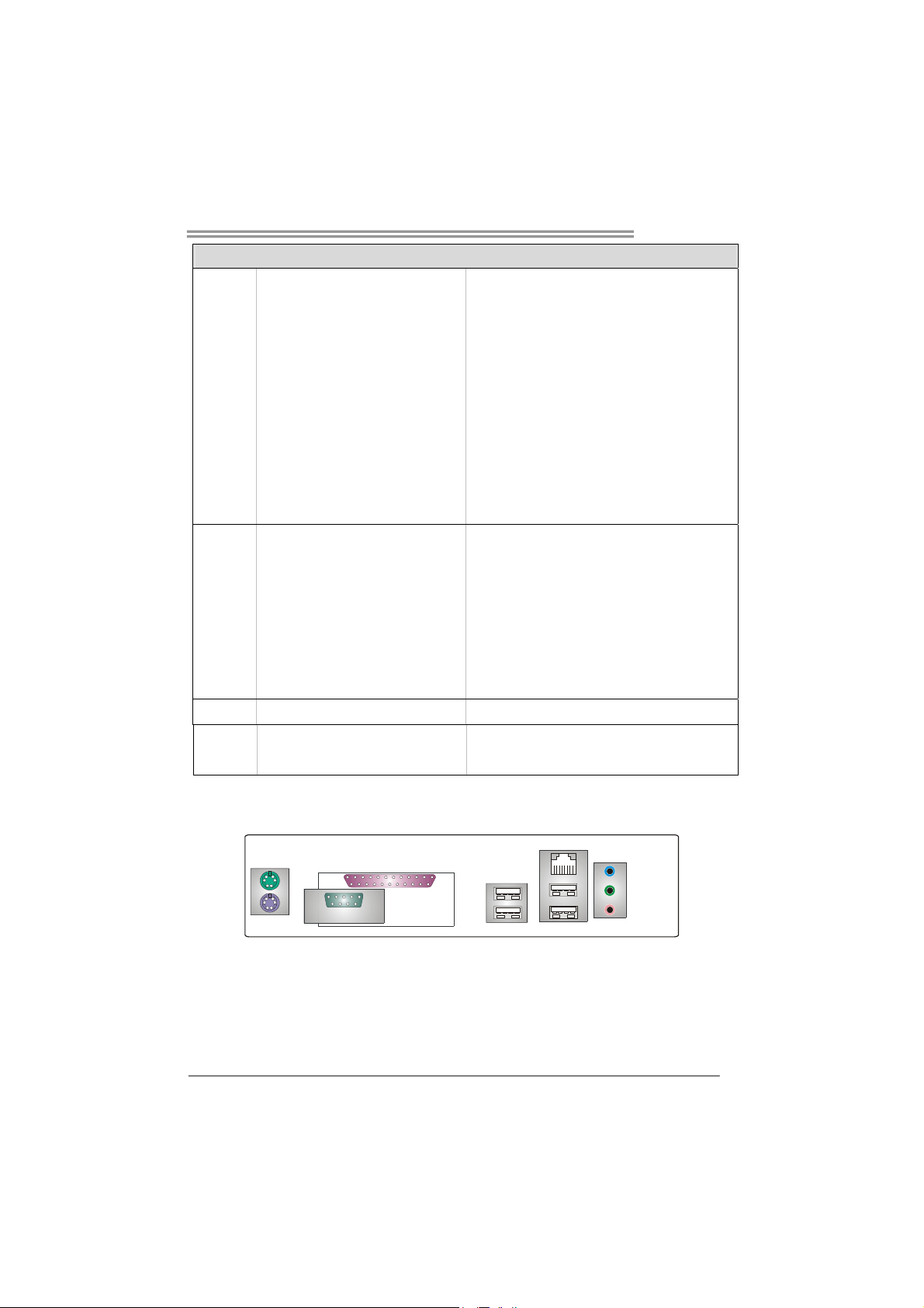
1.4 REAR PANEL CONNECTORS
PS/2
Mouse
PS/2
Keyboard
Printer Port
COM
USB x2
LAN
USB x2
Line In/
Surround
Line Out
Mic In 1/
Bass/Center
3
Page 6

Motherboard Manual
1.5 MOTHERBOARD LAYOUT
JATXPWR2
JKBMS1
C
O
M
JCOM1
1
JPRNT1
LGA775
CPU1
JATXPWR1
DDR2_A1
DDR2_B1
JCFAN1
JRJ45USB1
Super
JAUDIO2
LAN
JCDIN1
I/O
JSPDIF_IN1
(optional)
PCI-EX1_1
PCI-EX16
BIOS
JSPDIF_OUT1
PCI1
PCI2
JAUDIO1
CODEC
Note: ■ represents the 1
st
pin.
945PL
Intel
ICH7
SATA4
BAT1
SATA3
JPANEL1
IDE1
JCMOS1
JCI1
IR (optional)
FDD1
JSFAN1
SATA1
SATA2
4
Page 7
945PL-M7
CHAPTER 2: HARDWARE INSTALLATION
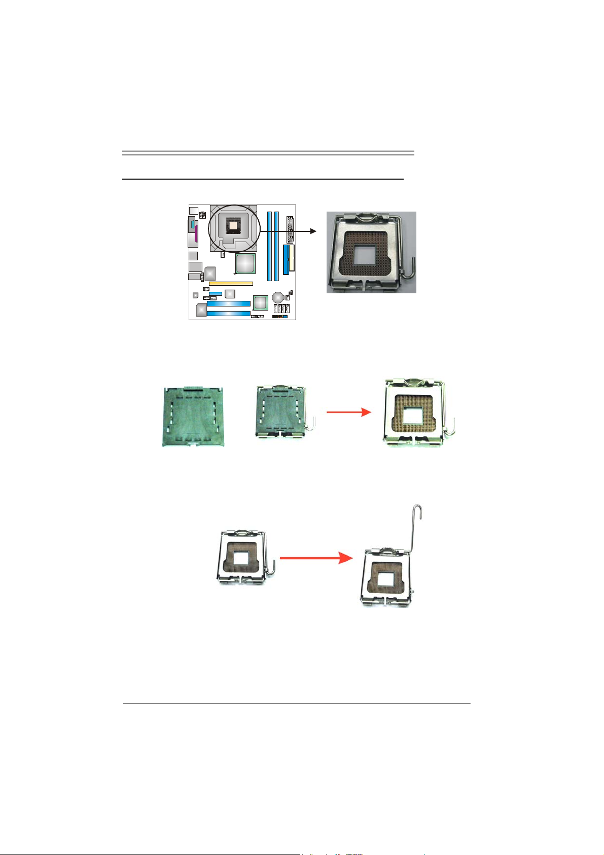
2.1 INSTALLING
CENTRAL PROCESSING UNIT (CPU)
Special Notice:
Remove Pin Cap before installation, and make good preservation
for future use. When the CPU is removed, cover the Pin Cap on the
empty socket to ensure pin legs won’t be damaged.
Pin Cap
Step 1: Pull the socket locking lever out from the socket and then raise
the lever up to a 90-degree angle.
5
Page 8
Motherboard Manual
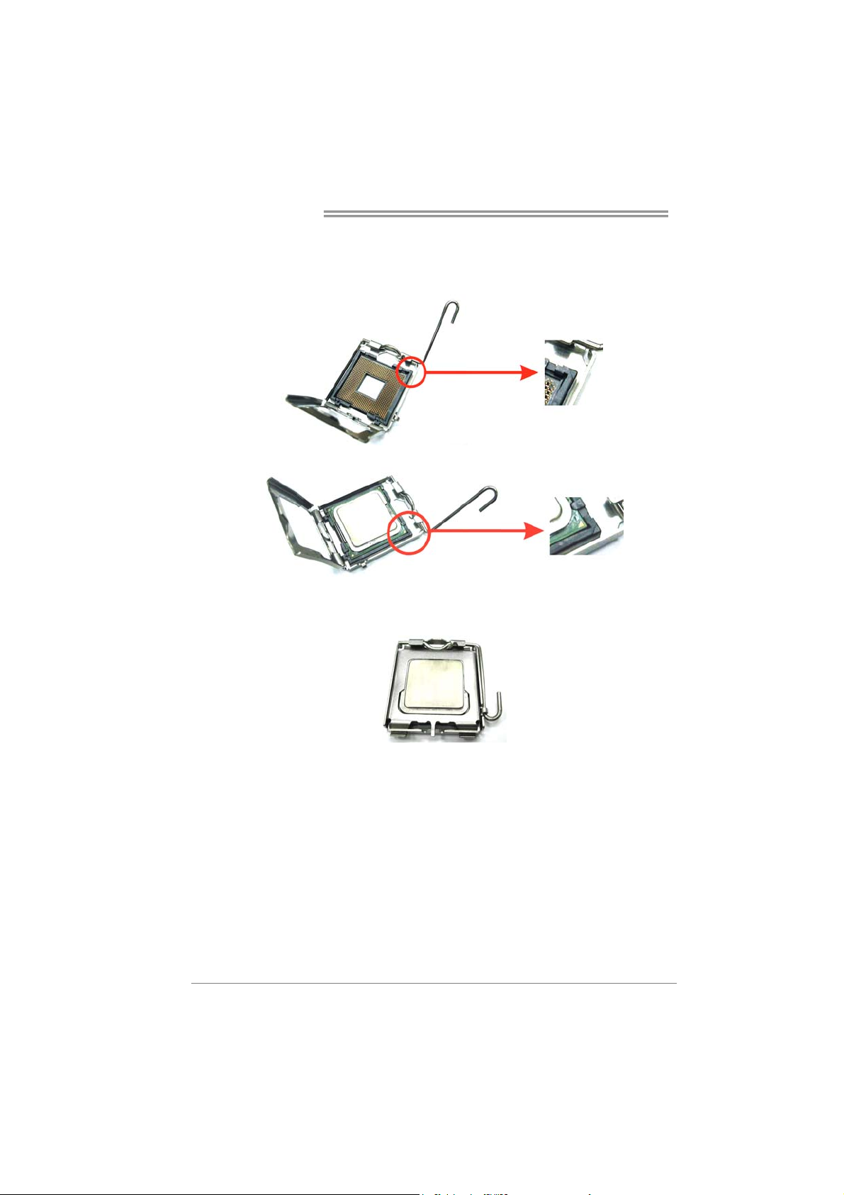
Step 2: Look for the triangular cut edge on socket, and the golden dot on
CPU should point forwards this triangular cut edge. The CPU will
fit only in the correct orientation.
Step 2-1:
Step 2-2:
Step 3: Hold the CPU down firmly, and then lower the lever to locked
position to complete the installation.
Step 4: Put the CPU Fan and heatsink assembly on the CPU and buckle it
on the retention frame. Connect the CPU FAN power cable into
the JCFAN1. This completes the installation.
6
Page 9
945PL-M7
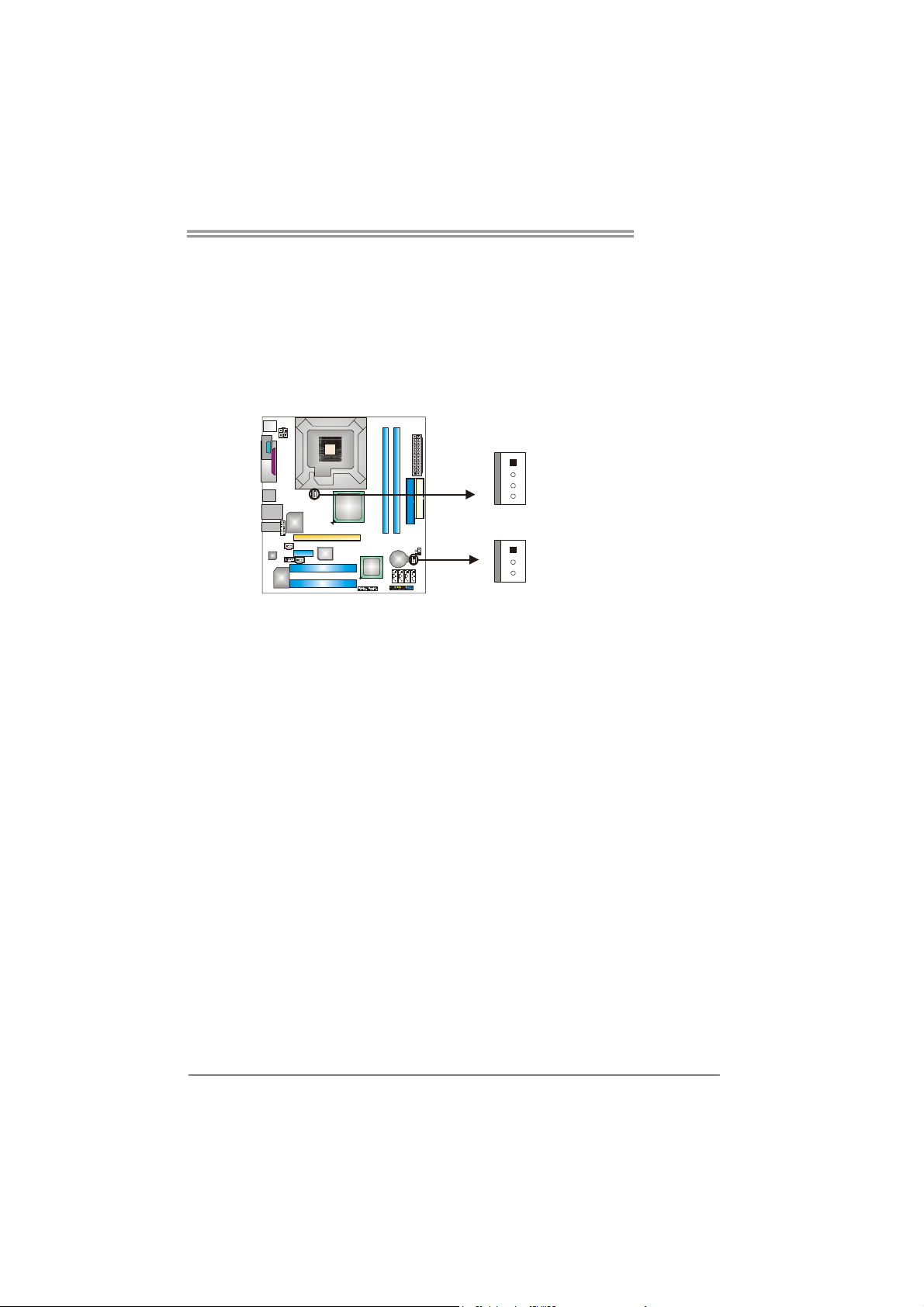
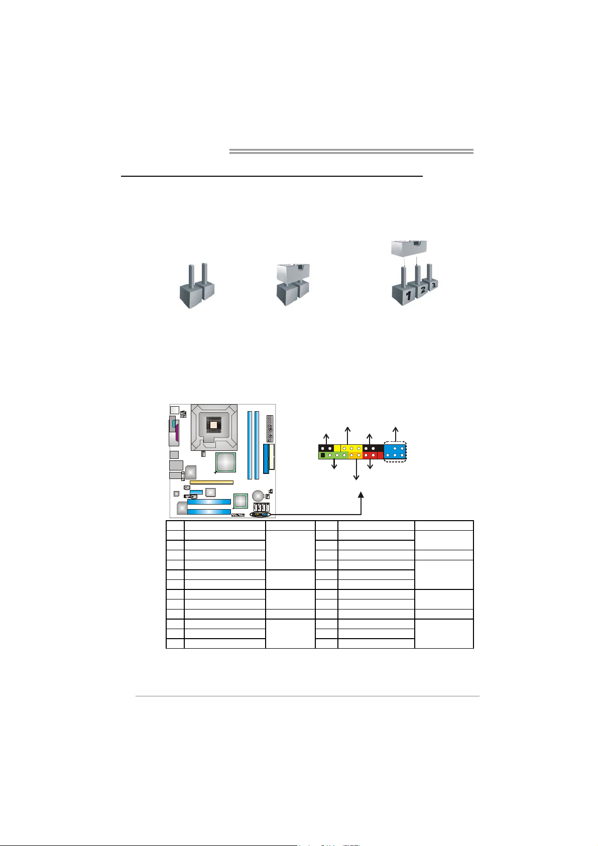
2.2 FAN HEADERS
These fan headers support cooling-fans built in the computer. The fan
cable and connector may be different according to the fan manufacturer.
Connect the fan cable to the connector while matching the black wire to
pin#1.
JCFAN1: CPU Fan Header
JSFAN1: System Fan Header
1
4
JCFAN1
1
3
JSFAN1
Note:
The JCFAN1 and JSFAN2 reserve system cooling fan with Smart Fan Control utility. It
supports 4-pin and 3-pin head connector. When connecting with wires onto connectors,
please note that the red wire is the positive and should be connected to pin#2, and the
black wire is Ground and should be connected to GND.
Pin
Assignment
1 Ground
2 +12V
3 FAN RPM rate
sense
7
Page 10

Motherboard Manual
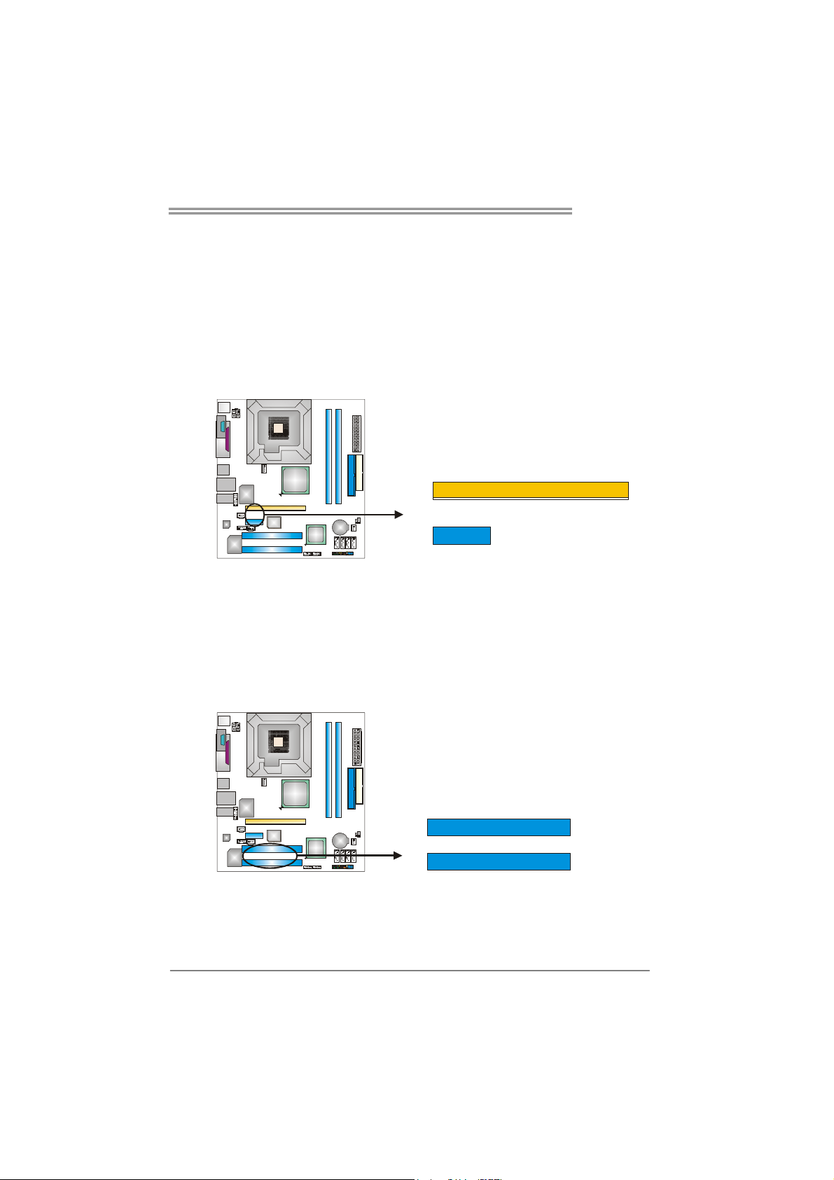
2.3 INSTALLING SYSTEM MEMORY
A. Memory Modules
DDR2_A1
DDR2_B1
1. Unlock a DIMM slot by pressing the retaining clips outward. Align a
DIMM on the slot such that the notch on the DIMM matches the
break on the Slot.
2. Insert the DIMM vertically and firmly into the slot until the retaining
chip snap back in place and the DIMM is properly seated.
B. Memory Capacity
DIMM Socket
Location
DDR2_A1 256MB/512MB/1GB *1
DDR2_B1 256MB/512MB/1GB *1
DDR Module
8
Total Memory
Size
Max is 2GB.
Page 11

945PL-M7
C. Dual Channel Memory installation
To trigger the Dual Channel function of the motherboard, the memory module
must meet the following requirements:
Install memory module of the same density in pairs, shown in the following
table.
Dual Channel Status
Disabled O X
Disabled X O
Enabled O O
(O means memory installed, X means memory not installed.)
The DRAM bus width of the memory module must be the same (x8 or
x16)
DDR2_A1
DDR2_B1
9
Page 12

Motherboard Manual
2.4 CONNECTORS AND SLOTS
FDD1: Floppy Disk Connector
The motherboard provides a standard floppy disk connector that supports 360K,
720K, 1.2M, 1.44M and 2.88M floppy disk types. This connector supports the
provided floppy drive ribbon cables.
IDE1/IDE2: Hard Disk Connectors
The motherboard has a 32-bit Enhanced PCI IDE Controller that provides PIO
Mode 0~4, Bus Master, and Ultra DMA 33/66/100/133 functionality. It has two
HDD connectors IDE1 (primary) and IDE2 (secondary).
The IDE connectors can connect a master and a slave drive, so you can
connect up to four hard disk drives. The first hard drive should always be
connected to IDE1.
34 33
12
10
3940
21
IDE1
Page 13
945PL-M7
PCI-Ex16: PCI-Express x16 Slot
- PCI-Express 1.0a compliant.
- Maximum theoretical realized bandwidth of 4GB/s simultaneously per
direction, for an aggregate of 8GB/s totally.
PCI-Ex1_1: PCI-Express x1 slots
- PCI-Express 1.0a compliant.
- Data transfer bandwidth up to 250MB/s per direction; 500MB/s in total.
- PCI-Express supports a raw bit-rate of 2.5Gb/s on the data pins.
- 2X bandwidth over the traditional PCI architecture.
PCI-EX16
PCI-EX1_1
PCI1~PCI2: Peripheral Component Interconnect Slots
This motherboard is equipped with 2 standard PCI slots. PCI stands for
Peripheral Component Interconnect, and it is a bus standard for expansion
cards. This PCI slot is designated as 32 bits.
PCI1
PCI2
11
Page 14
Motherboard Manual
CHAPTER 3: HEADERS & JUMPERS SETUP
3.1 HOW
TO SETUP JUMPERS
The illustration shows how to set up jumpers. When the jumper cap is
placed on pins, the jumper is “close”, if not, that means the jumper is
“open”.
Pin opened Pin closed Pin1-2 closed
3.2 DETAIL SETTINGS
JPANEL1: Front Panel Header
This 24-pin connector includes Power-on, Reset, HDD LED, Power LED, Sleep
button, speaker and IrDA Connection. It allows user to connect the PC case’s
front panel switch functions.
2
1
SLP
SPK
PWR_LED
++
+
HLED
On/Off
-
-
RST
IR (optional)
24
23
12
Pin Assignment Function Pin Assignment Function
1 +5V 2 Sleep control
3 N/A 4 Ground
5 N/A 6 N/A N/A
7 Speaker
9 HDD LED (+) 10 Power LED (+)
11 HDD LED (-)
13 Ground 14 Power button
15 Reset control
17 N/A 18 Key
19 N/A 20 Key
21 +5V 22 Ground
23 IRTX
Speaker
Connector
Hard drive
LED
Reset button
IrDA
Connector
8 Power LED (+)
12 Power LED (-)
16 Ground
24 IRRX
Sleep button
Power LED
Power-on button
IrDA Connector
Page 15
945PL-M7
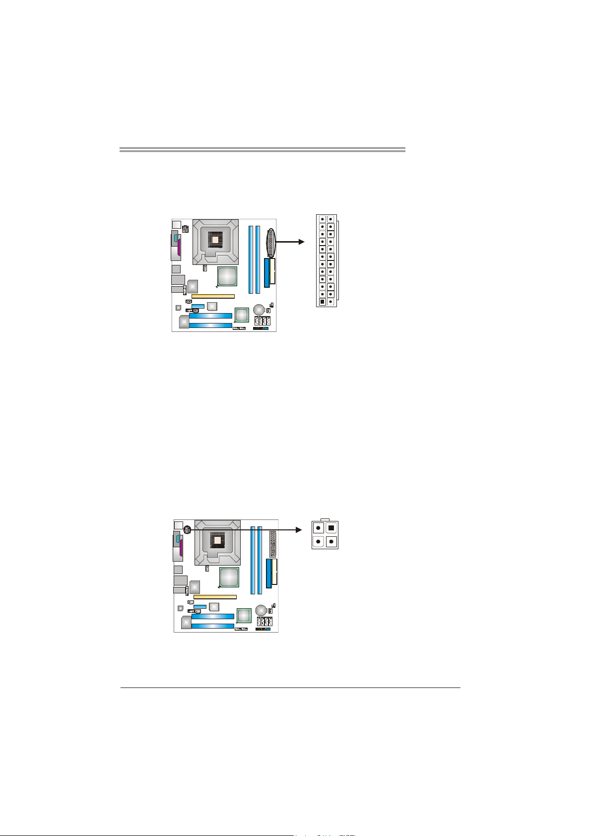
ATX Power Source Connector: JATXPWR1
JATXPWR1 allows user to connect 24-pin power connector on the ATX power
supply.
12
1
Pin Assignment Pin Assignment
24
13
13 +3.3V 1 +3.3V
14 -12V 2 +3.3V
15 Ground 3 Ground
16 PS_ON 4 +5V
17 Ground 5 Ground
18 Ground 6 +5V
19 Ground 7 Ground
20 NC 8 PW_OK
21 +5V 9 Standby Voltage+5V
22 +5V 10 +12V
23 +5V 11 +12V
24 Ground 12 +3.3V
JATXPWR2: ATX Power Source Connector
By connecting this connector, it will provide +12V to CPU power circuit.
12
4
3
Pin
Assignment
1 +12V
2 +12V
3 Ground
4 Ground
13
Page 16
Motherboard Manual
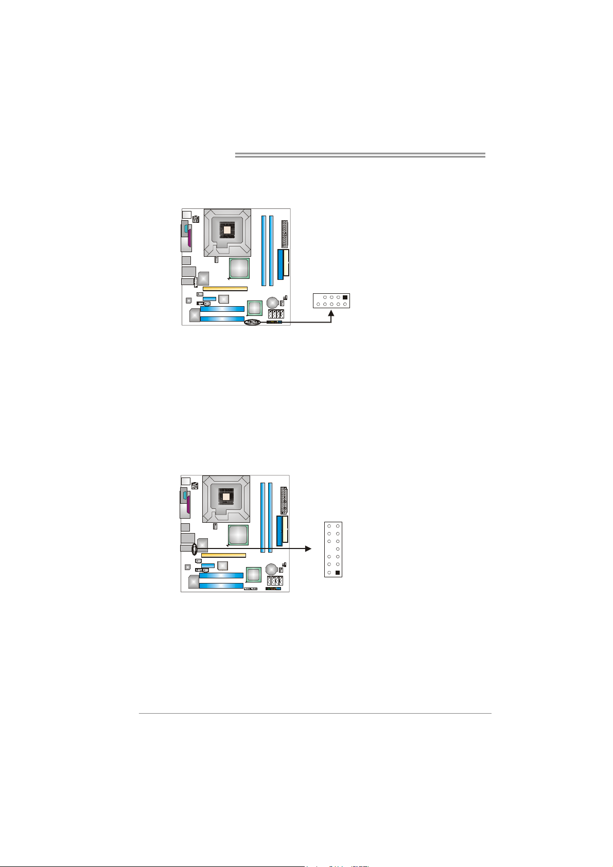
JUSB3/JUSB4: Headers for USB 2.0 Ports at Front Panel
This header allows user to connect additional USB cable on the PC front panel,
and also can be connected with internal USB devices, like USB card reader.
JUSB3 JUSB4
1
9
2
10
JAUDIO2: Front Panel Audio Header
This header allows user to connect the front audio output cable with the PC front
panel. It will disable the output on back panel audio connectors.
Pin Assignment
1314
12
1 Mic in/center
2 Ground
3 Mic power/Bass
4 Audio power
5 Right line out/
6 Right line out/
7 Reserved
8 Key
9 Left line out/
10 Left line out/
11 Right line in/
12 Right line in/
13 Left line in/
14 Left line in/
Assignment
Pin
1 +5V (fused)
2 +5V (fused)
3 USB4 USB5 USB+
6 USB+
7 Ground
8 Ground
9 Key
10 NC
Speaker out Right
Speaker out Right
Speaker out Left
Speaker out Left
Rear speaker Right
Rear speaker Right
Rear speaker Left
Rear speaker Left
14
Page 17
945PL-M7
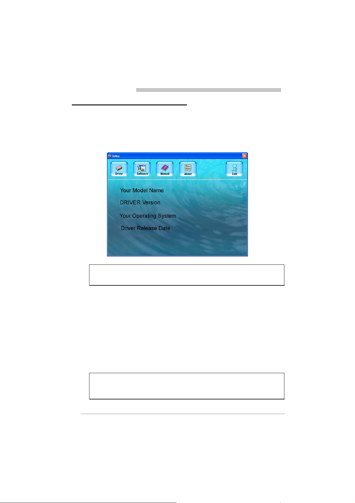
JCDIN1: CD-ROM Audio-in Connector
This connector allows user to connect the audio source from the variaty devices,
like CD-ROM, DVD-ROM, PCI sound card, PCI TV turner card etc.
Pin
Assignment
1 Left Channel
Input
2 Ground
14
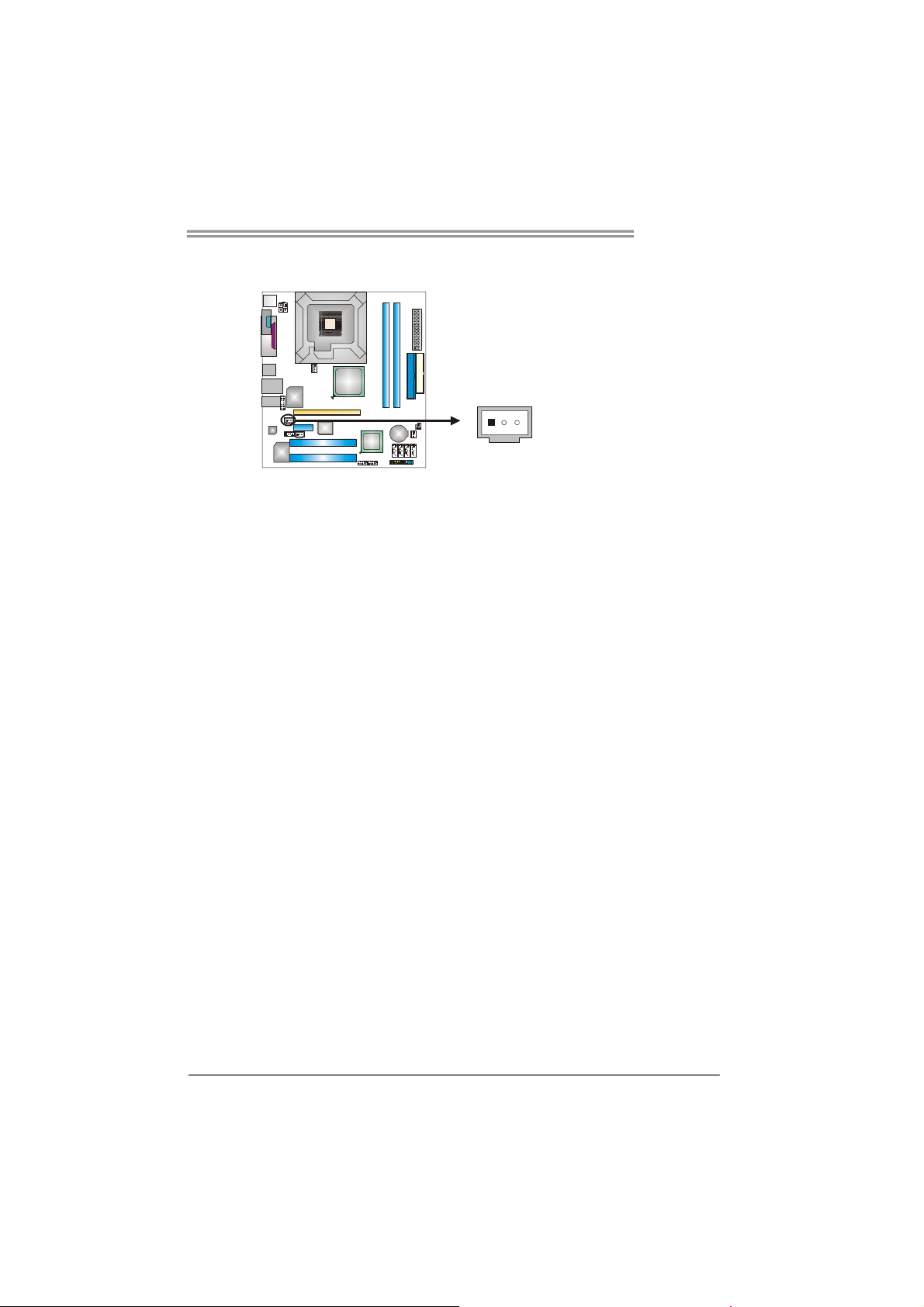
JCMOS1: Clear CMOS Header
By placing the jumper on pin2-3, it allows user to restore the BIOS safe setting
and the CMOS data, please carefully follow the procedures to avoid damaging
the motherboard.
3
1
3 Ground
4 Right Channel
Input
1
3
Pin 1-2 Close:
Normal Operation (default).
1
3
Pin 2-3 Close:
Clear CMOS data.
※ Clear CMOS Procedures:
1. Remove AC power line.
2. Set the jumper to “Pin 2-3 close”.
3. Wait for five seconds.
4. Set the jumper to “Pin 1-2 close”.
5. Power on the AC.
6. Reset your desired password or clear the CMOS data.
15
Page 18

Motherboard Manual
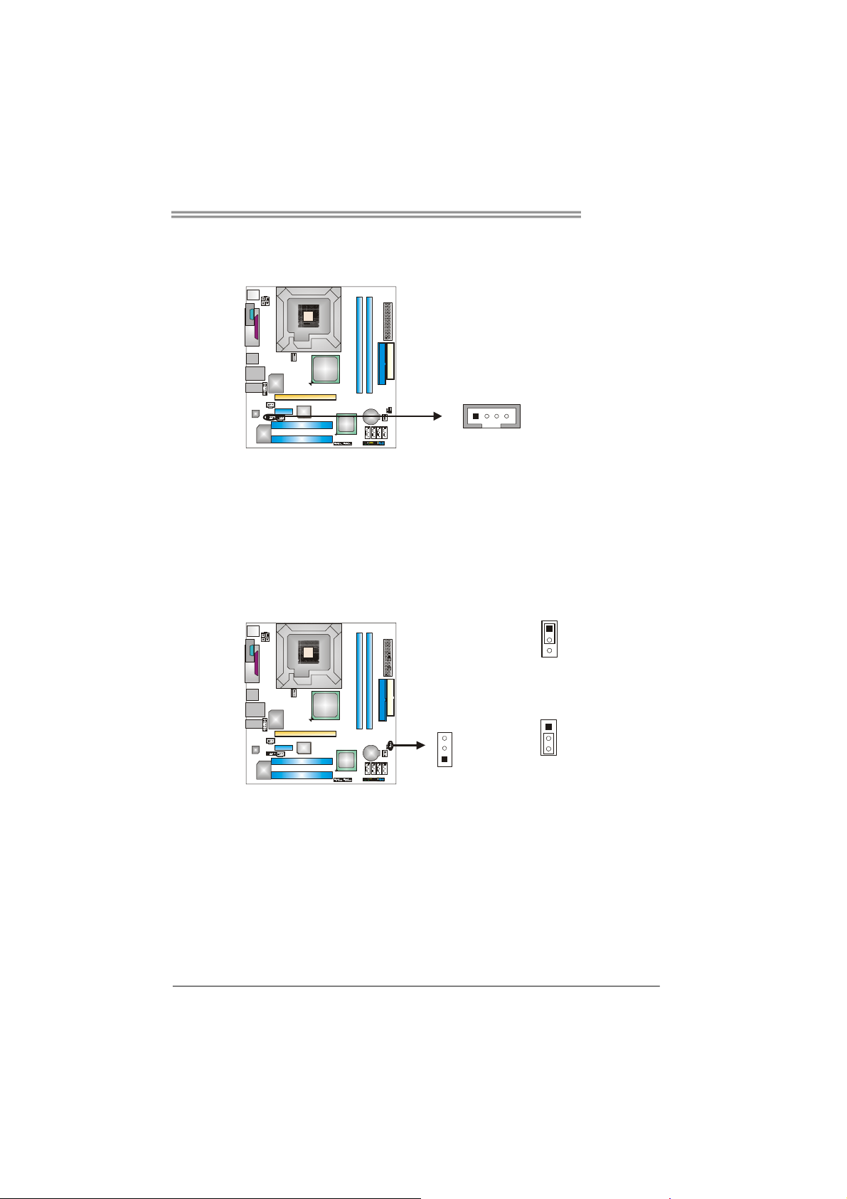
JCI1: Chassis Open Header
This connector allows system to monitor PC case open status. If the signal has
been triggered, it will record to the CMOS and show the message on next
boot-up.
JSATA1~JSATA4: Serial ATA Connectors
The motherboard has a PCI to SATA Controller with 4 channels SATA interface,
it satisfies the SATA2.0spec and with transfer rate of 3.0GB/s.
SATA4 SATA3 SATA2 SATA1
Pin
Assignment
1 Case open signal
2 Ground
2
1
Pin
Assignment
1 Ground
2 TX+
3 TX-
1
4
7
4 Ground
5 RX6 RX+
7 Ground
JSPDIF_OUT1: Digital Audio-out Connector
This connector allows user to connect the PCI bracket SPDIF output header.
16
13
Assignment
Pin
1 +5V
2 SPDIF_OUT
3 Ground
Page 19
945PL-M7
JSPDIF_IN1 (optional): Digital Audio-in Connector
This connector allows user to connect the PCI bracket SPDIF input header.
Pin
Assignment
1 +5V
2 SPDIF_IN
13
3 Ground
17
Page 20
Motherboard Manual
CHAPTER 4: USEFUL HELP
4.1 DRIVER
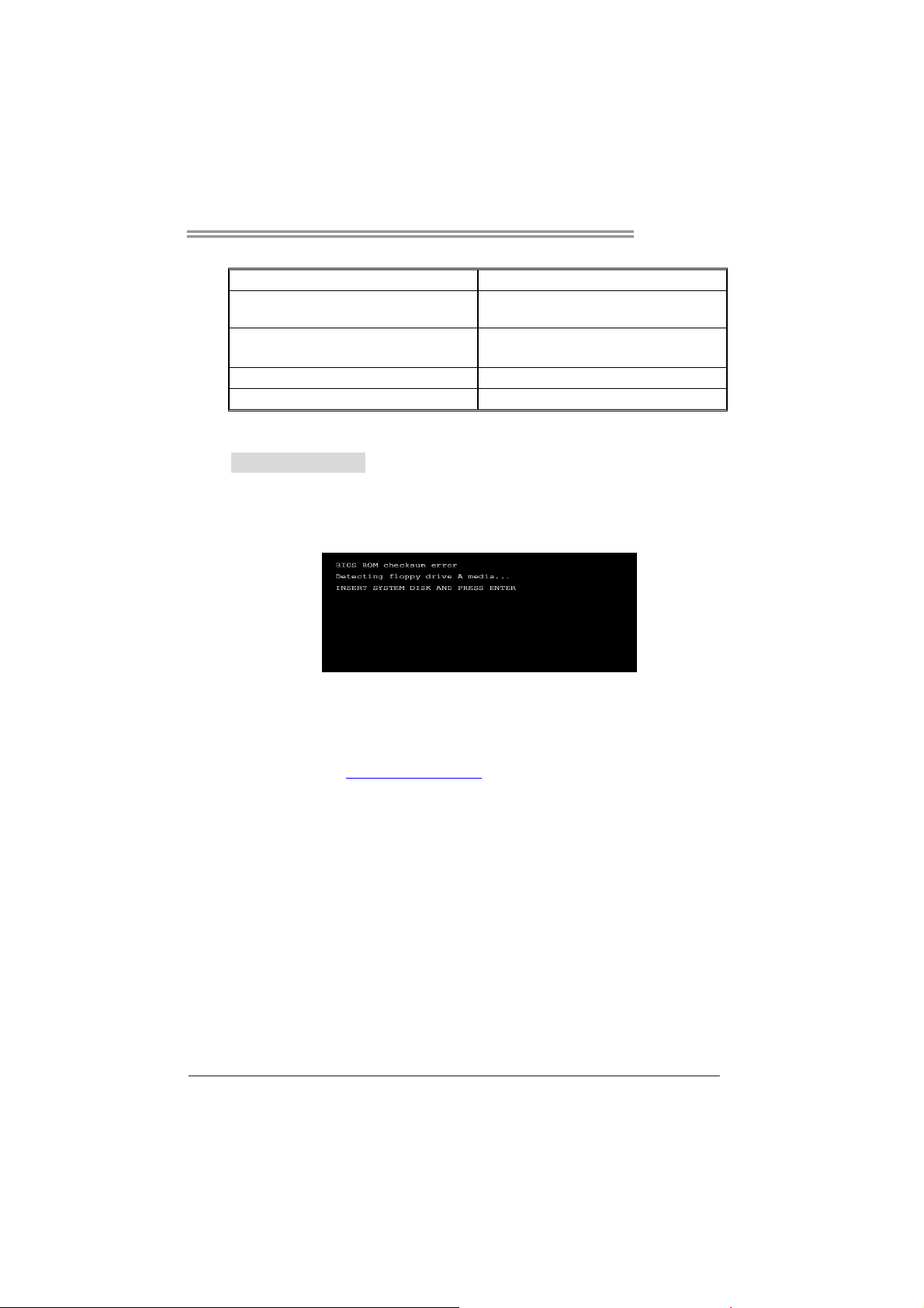
After you installed your operating system, please insert the Fully Setup
Driver CD into your optical drive and install the driver for better system
performance.
You will see the following window after you insert the CD
The setup guide will auto detect your motherboard and operating system.
Note:
If this window didn’t show up after you insert the Driver CD, please use file browser to
locate and execute the file SETUP.EXE under your optical drive.
INSTALLATION NOTE
A. Driver Installation
To install the driver, please click on the Driver icon. The setup guide will
list the compatible driver for your motherboard and operating system.
Click on each device driver to launch the installation program.
B. Software Installation
To install the software, please click on the Software icon. The setup guide
will list the software available for your system, click on each software title
to launch the installation program.
C. Manual
Aside from the paperback manual, we also provide manual in the Driver
CD. Click on the Manual icon to browse for available manual.
Note:
You will need Acrobat Reader to open the manual file. Please download the latest version
of Acrobat Reader software from
http://www.adobe.com/products/acrobat/readstep2.html
18
Page 21
945PL-M7
4.2 AWARD BIOS BEEP CODE
Beep Sound Meaning
One long beep followed by two short
beeps
High-low siren sound CPU overheated
One Short beep when system boot-up No error found during POST
Long beeps every other second No DRAM detected or install
Video card not found or video card
memory bad
System will shut down automatically
4.3 EXTRA INFORMATION
A. BIOS Update
After you fail to update BIOS or BIOS is invaded by virus, the
Boot-Block function will help to restore BIOS. If the following message
is shown after boot-up the system, it means the BIOS contents are
corrupted.
In this Case, please follow the procedure below to restore the BIOS:
1. Make a bootable floppy disk.
2. Download the Flash Utility “AWDFLASH.exe” from the Biostar
website: www.biostar.com.tw
3. Confirm motherboard model and download the respectively BIOS
from Biostar website.
4. Copy “AWDFLASH.exe” and respectively BIOS into floppy disk.
5. Insert the bootable disk into floppy drive and press Enter.
6. System will boot-up to DOS prompt.
7. Type “Awdflash xxxx.bf/sn/py/r” in DOS prompt.
(xxxx means BIOS name.)
8. System will update BIOS automatically and restart.
9. The BIOS has been recovered and will work properly.
19
Page 22

Motherboard Manual
B. CPU Overheated
If the system shutdown automatically after power on system for
seconds, that means the CPU protection function has been activated.
When the CPU is over heated, the motherboard will shutdown
automatically to avoid a damage of the CPU, and the system may not
power on again.
In this case, please double check:
1. The CPU cooler surface is placed evenly with the CPU surface.
2. CPU fan is rotated normally.
3. CPU fan speed is fulfilling with the CPU speed.
After confirmed, please follow steps below to relief the CPU protection
function.
1. Remove the power cord from power supply for seconds.
2. Wait for seconds.
3. Plug in the power cord and boot up the system.
Or you can:
1. Clear the CMOS data.
(See “Close CMOS Header: JCMOS1” section)
2. Wait for seconds.
3. Power on the system again.
20
Page 23

945PL-M7
4.4 TROUBLESHOOTING
Probable Solution
1. No power to the system at all
Power light don’t illuminate, fan
inside power supply does not turn
on.
2. Indicator light on keyboard does
not turn on.
System inoperative. Keyboard lights
are on, power indicator lights are lit,
and hard drive is spinning.
System does not boot from hard disk
drive, can be booted from optical drive.
System only boots from optical drive.
Hard disk can be read and applications
can be used but booting from hard disk
is impossible.
Screen message says “Invalid
Configuration” or “CMOS Failure.”
Cannot boot system after installing
second hard drive.
1. Make sure power cable is
securely plugged in.
2. Replace cable.
3. Contact technical support.
Using even pressure on both ends of
the DIMM, press down firmly until the
module snaps into place.
1. Check cable running from disk to
disk controller board. Make sure
both ends are securely plugged
in; check the drive type in the
standard CMOS setup.
2. Backing up the hard drive is
extremely important. All hard
disks are capable of breaking
down at any time.
1. Back up data and applications
files.
2. Reformat the hard drive.
Re-install applications and data
using backup disks.
Review system’s equipment. Make sure
correct information is in setup.
1. Set master/slave jumpers
correctly.
2. Run SETUP program and select
correct drive types. Call the drive
manufacturers for compatibility
with other drives.
21
Page 24

Motherboard Manual
CHAPTER 6: WARPSPEEDER™
6.1 INTRODUCTION
[WarpSpeeder™], a new powerful control utility, features three
user-friendly functions including Overclock Manager, Overvoltage
Manager, and Hardware Monitor.
With the Overclock Manager, users can easily adjust the frequency they
prefer or they can get the best CPU performance with just one click. The
Overvoltage Manager, on the other hand, helps to power up CPU core
voltage and Memory voltage. The cool Hardware Monitor smartly indicates
the temperatures, voltage and CPU fan speed as well as the chipset
information. Also, in the About panel, you can get detail descriptions about
BIOS model and chipsets. In addition, the frequency status of CPU,
memory, AGP and PCI along with the CPU speed are synchronically
shown on our main panel.
Moreover, to protect users' computer systems if the setting is not
appropriate when testing and results in system fail or hang,
[WarpSpeeder™] technology assures the system stability by automatically
rebooting the computer and then restart to a speed that is either the
original system speed or a suitable one.
6.2 SYSTEM REQUIREMENT
OS Support: Windows 98 SE, Windows Me, Windows 2000, Windows XP
DirectX: DirectX 8.1 or above. (The Windows XP operating system
includes DirectX 8.1. If you use Windows XP, you do not need to install
DirectX 8.1.)
22
Page 25
945PL-M7
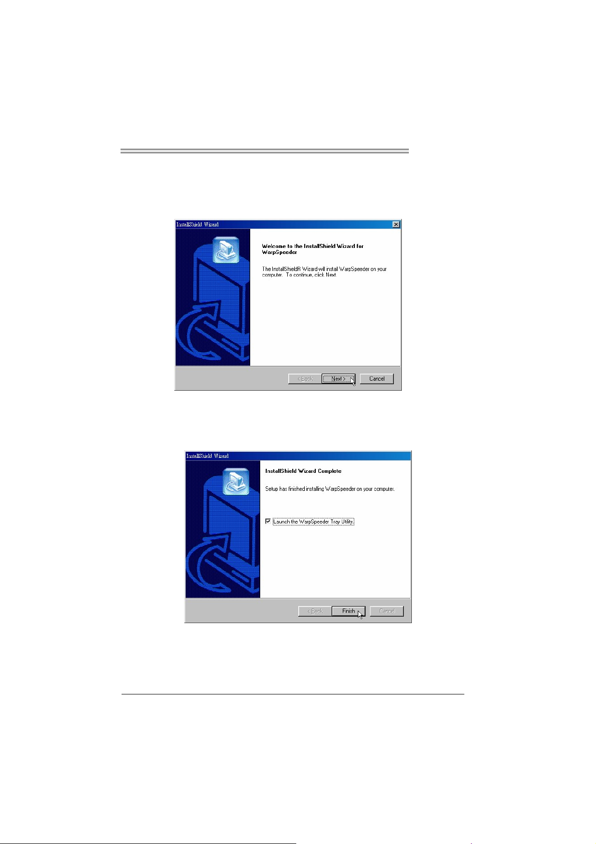
6.3 INSTALLATION
1. Execute the setup execution file, and then the following dialog will pop
up. Please click “Next” button and follow the default procedure to
install.
2. When you see the following dialog in setup procedure, it means setup
is completed. If the “Launch the WarpSpeeder Tray Utility” checkbox
is checked, the Tray Icon utility and [WarpSpeeder™] utility will be
automatically and immediately launched after you click “Finish”
button.
Usage:
The following figures are just only for reference, the screen printed in
this user manual will change according to your motherboard on hand.
23
Page 26

Motherboard Manual
6.4 WARPSPEEDER™
1. Tray Icon:
Whenever the Tray Icon utility is launched, it will display a little tray
icon on the right side of Windows Taskbar.
This utility is responsible for conveniently invoking [WarpSpeeder™]
Utility. You can use the mouse by clicking the left button in order to
invoke [WarpSpeeder™] directly from the little tray icon or you can
right-click the little tray icon to pop up a popup menu as following
figure. The “Launch Utility” item in the popup menu has the same
function as mouse left-click on tray icon and “Exit” item will close
Tray Icon utility if selected.
24
Page 27

945PL-M7
2. Main Panel
If you click the tray icon, [WarpSpeeder™] utility will be invoked.
Please refer to the following figure; the utility’s first window you will
see is Main Panel.
Main Panel contains features as follows:
a. Display the CPU Speed, CPU external clock, Memory clock, AGP clock,
and PCI clock information.
b. Contains About, Voltage, Overclock, and Hardware Monitor Buttons for
invoking respective panels.
c. With a user-friendly Status Animation, it can represent 3 overclock
percentage stages:
Man walking→overclock percentage from 100% ~ 110 %
Panther running→overclock percentage from 110% ~ 120%
Car racing→overclock percentage from 120% ~ above
25
Page 28

Motherboard Manual
3. Voltage Panel
Click the Voltage button in Main Panel, the button will be highlighted
and the Voltage Panel will slide out to up as the following figure.
In this panel, you can decide to increase CPU core voltage and
Memory voltage or not. The default setting is “No”. If you want to get
the best performance of overclocking, we recommend you click the
option “Yes”.
26
Page 29

945PL-M7
4. Overclock Panel
Click the Overclock button in Main Panel, the button will be
highlighted and the Overclock Panel will slide out to left as the
following figure.
Overclock Panel contains the these features:
a. “–3MHz button”, “-1MHz button”, “+1MHz button”, and “+3MHz button”:
provide user the ability to do real-time overclock adjustment.
Warning:
Manually overclock is potentially dangerous, especially when the
overclocking percentage is over 110 %. We strongly recommend you
verify every speed you overclock by click the Verify button. Or, you can
just click Auto overclock button and let [WarpSpeeder™] automatically
gets the best result for you.
b. “Recovery Dialog button”: Pop up the following dialog. Let user select
a restoring way if system need to do a fail-safe reboot.
27
Page 30

Motherboard Manual
c. “Auto-overclock button”: User can click this button and
[WarpSpeeder™] will set the best and stable performance and
frequency automatically. [WarpSpeeder™] utility will execute a
series of testing until system fail. Then system will do fail-safe
reboot by using Watchdog function. After reboot, the
[WarpSpeeder™] utility will restore to the hardware default
setting or load the verified best and stable frequency according
to the Recovery Dialog’s setting.
d. “Verify button”: User can click this button and [WarpSpeeder™]
will proceed a testing for current frequency. If the testing is ok,
then the current frequency will be saved into system registry. If
the testing fail, system will do a fail-safe rebooting. After reboot,
the [WarpSpeeder™] utility will restore to the hardware default
setting or load the verified best and stable frequency according
to the Recovery Dialog’s setting.
Note:
Because the testing programs, invoked in Auto-overclock and Verify,
include DirectDraw, Direct3D and DirectShow tests, the DirectX 8.1 or
newer runtime library is required. And please make sure your display
card’s color depth is High color (16 bit) or True color( 24/32 bit ) that is
required for Direct3D rendering.
5. Hardware Monitor Panel
Click the Hardware Monitor button in Main Panel, the button will be
highlighted and the Hardware Monitor panel will slide out to left as
the following figure.
In this panel, you can get the real-time status information of your
system. The information will be refreshed every 1 second.
28
Page 31

945PL-M7
6. About Panel
Click the “about” button in Main Panel, the button will be highlighted
and the About Panel will slide out to up as the following figure.
In this panel, you can get model name and detail information in hints
of all the chipset that are related to overclocking. You can also get
the mainboard’s BIOS model and the Version number of
[WarpSpeeder™] utility.
Note:
Because the overclock, overvoltage, and hardware monitor features
are controlled by several separate chipset, [WarpSpeeder™] divide
these features to separate panels. If one chipset is not on board, the
correlative button in Main panel will be disabled, but will not interfere
other panels’ functions. This property can make [WarpSpeeder™]
utility more robust.
29
Page 32

Motherboard Manual
APPENDENCIES: SPEC IN OTHER LANGUAGE
G
ERMAN
Spezifikationen
LGA 775
CPU
FSB 533 / 800 MHz
Chipsatz Intel 945PL Intel ICH7
Super E/A
Arbeitsspeic
her
IDE
SATA II
LAN
Audio-Code
c
Steckplätze
Onboard-An Diskettenlaufwerkanschluss x1 Jeder Anschluss unterstützt 2 Diskettenlaufwerke
Intel Pentium 4 / Pentium D /
Celeron D Prozessoren mit bis zu 3,8
GHz
ITE 8712F
Bietet die häufig verwendeten alten
Super E/A-Funktionen.
Low Pin Count-Schnittstelle
DDR2 DIMM-Steckplätze x 2
Jeder DIMM unterstützt
256/512MB & 1GB DDR2.
Max. 2GB Arbeitsspeicher
Integrierter IDE-Controller
Ultra DMA 33 / 66 / 100 Bus
Master-Modus
Integrierter Serial ATA-Controller
Datentransferrate bis zu 3Gb/s
Realtek RTL 8100C /
RTL 8100SC (optional)
ALC 655
PCI-Steckplatz x2
PCI Express x16 Steckplatz x1
PCI Express x 1-Steckplatz x1
Unterstützt Hyper-Threading / Execute Disable
Bit / Enhanced Intel SpeedStep® / Intel
Architecture-64 / Extended Memory 64
Technology
Umgebungskontrolle,
Hardware-Überwachung
Lüfterdrehzahl-Controller
"Smart Guardian"-Funktion von ITE
Dual-Kanal DDR2 Speichermodul
Unterstützt DDR2 400 / 533
registrierte DIMMs. Nicht-ECC DIMMs werden
nicht unterstützt.
Unterstützt PIO-Modus 0~4,
Konform mit der SATA-Spezifikation Version 2.0.
10 / 100 Mb/s Auto-Negotiation
(Gigabit-Bandbreite nur beim RTL 8100SC)
Halb-/ Vollduplex-Funktion
6-Kanal-Audioausgabe
AC’97 Version 2.3
30
Page 33

945PL-M7
Spezifikationen
schluss
Rückseiten-
E/A
Platinengrö
ße.
OS-Unterst
ützung
IDE-Anschluss x1 Jeder Anschluss unterstützt 2 IDE-Laufwerke
SATA-Anschluss x4 Jeder Anschluss unterstützt 1 SATA-Laufwerk
Fronttafelanschluss x1 Unterstützt die Fronttafelfunktionen
Front-Audioanschluss x1
CD-IN-Anschluss x1 Unterstützt die CD Audio-In-Funktion
S/PDIF-Ausgangsanschluss x1 Unterstützt die digitale Audioausgabefunktion
S/PDIF Eingangsanschluss
(optional) x1
CPU-Lüfter-Sockel x1
System-Lüfter-Sockel x1 System-Lüfter-Stromversorgungsanschluss
"Gehäuse offen"-Sockel x1 Zur Erkennung eines geöffneten Gehäuses
"CMOS löschen"-Sockel x1
USB-Anschluss x2 Jeder Anschluss unterstützt 2
Stromanschluss (24-polig) x1
Stromanschluss (4-polig) x1
PS/2-Tastatur x1
PS/2-Maus x1
Serieller Anschluss x1
LAN-Anschluss x1
USB-Anschluss x4
Audioanschluss x3
219 mm (B) X 236 mm (L)
Windows 2K / XP
Unterstützt die
Fronttafel-Audioanschlussfunktion
Unterstützt die digitale Audioeingabefunktion
CPU-Lüfterstromversorgungsanschluss (mit
Smart Fan-Funktion)
Fronttafel-USB-Anschlüsse
Biostar behält sich das Recht vor, ohne
Ankündigung die Unterstützung für ein
Betriebssystem hinzuzufügen oder zu entfernen.
31
Page 34

Motherboard Manual
FRANCE
SPEC
LGA 775
UC
Bus frontal 533 / 800 / 1066 MHz
Chipset Intel 945PL Intel ICH7
Super E/S
Mémoire
principale
IDE
SATA
SATA II
LAN
Codec
audio
Fentes
Connecteu
r
embarqué
Processeurs Intel Pentium 4 / Pentium
D / Celeron D jusqu'à 3,8 GHz
ITE 8712F
Fournit la fonctionnalité de Super E/S
patrimoniales la plus utilisée.
Interface à faible compte de broches
Fentes DDR2 DIMM x 2
Chaque DIMM prend en charge des
DDR2 de 256/512 Mo et 1Go
Capacité mémoire maximale de 2 Go
Contrôleur IDE intégré
Mode principale de Bus Ultra DMA 33 /
66 / 100
Contrôleur Serial ATA intégré :
Taux de transfert jusqu'à 3 Go/s.
Realtek RTL 8100C /
RTL 8100SC (optional)
ALC 655
Fente PCI x2
Slot PCI Express x16 x1
Slot PCI Express x 1 x1
Connecteur de disquette x1
Connecteur IDE x1
Prend en charge les technologies
Hyper-Threading / d'exécution de bit de
désactivation / Intel SpeedStep® optimisée/
d'architecture Intel 64 / de mémoire étendue 64
Initiatives de contrôle environnementales,
Moniteur de matériel
Contrôleur de vitesse de ventilateur
Fonction "Gardien intelligent" de l'ITE
Module de mémoire DDR2 à mode à double voie
Prend en charge la DDR2 400 / 533
Les DIMM à registres et DIMM sans code
correcteurs d'erreurs ne sont pas prises en
charge
Prend en charge le mode PIO 0~4,
Conforme à la spécification SATA Version 2.0
10 / 100 Mb/s négociation automatique (La
bande passante Gigabit est pour le RTL 8100SC
uniquement)
Half / Full duplex capability
Sortie audio à 6 voies
AC’97 Version 2.3
Chaque connector prend en charge 2 lecteurs de
disquettes
Chaque connecteur prend en charge 2
périphériques IDE
32
Page 35

945PL-M7
SPEC
Chaque connecteur prend en charge 1
périphérique SATA
Prend en charge les équipements du panneau
avant
Prend en charge la fonction audio du panneau
avant
Prend en charge la fonction de sortie audio
numérique
Prend en charge la fonction d'entrée audio
numérique
Alimentation électrique du ventilateur UC (avec
fonction de ventilateur intelligent)
Pour la fonction de détection d'intrus dans le
châssis
Chaque connecteur prend en charge 2 ports USB
de panneau avant
Biostar se réserve le droit d'ajouter ou de
supprimer le support de SE avec ou sans préavis.
E/S du
panneau
arrière
Dimension
s de la
carte
Support
SE
Connecteur SATA x4
Connecteur du panneau avant x1
Connecteur Audio du panneau
avantx1 x1
Connecteur d'entrée CD x1 Prend en charge la fonction d'entrée audio de CD
Connecteur de sortie S/PDIF x1
Connecteur d'entrée S/PDIF x1
(en option)
Embase de ventilateur UC x1
Embase de ventilateur système x1 Alimentation électrique du ventilateur système
Embase d'ouverture de châssis x1
Embase d'effacement CMOS x1
Connecteur USB x2
Connecteur d'alimentation x1
(24 broches)
Connecteur d'alimentation x1
(4 broches)
Clavier PS/2 x1
Souris PS/2 x1
Port série x1
Port LAN x1
Port USB x4
Fiche audio x3
219 mm (l) X 236 mm (H)
Windows 2K / XP
33
Page 36

Motherboard Manual
ITALIAN
SPECIFICA
LGA 775
CPU
FSB 533 / 800 MHz
Chipset Intel 945PL Intel ICH7
Super I/O
Memoria
principale
IDE
SATA II
LAN
Codec
audio
Alloggi
Connettori Connettore floppy x1 Ciascun connettore supporta 2 unità Floppy
Processore Intel Pentium 4 / Pentium
D / Celeron D fino a 3.8 GHz
ITE 8712F
Fornisce le funzionalità legacy Super
I/O usate più comunemente.
Interfaccia LPC (Low Pin Count)
Alloggi DIMM DDR2 x 2
Ciascun DIMM supporta DDR2
256/512MB e 1GB
Capacità massima della memoria 2GB
Controller IDE integrato
Modalità Bus Master Ultra DMA 33 /
66 / 100
Controller Serial ATA integrato
Velocità di trasferimento dei dati fino
a 3 Gb/s.
Realtek RTL 8100C /
RTL 8100SC(optional)
ALC 655
Alloggio PCI x2
Alloggio PCI Express x16 x1
Alloggio PCI Express x1 x1
Supporto di Hyper-Threading / Execute Disable
Bit / Enhanced Intel SpeedStep® / Architettura
Intel 64 / Tecnologia Extended Memory 64
Funzioni di controllo dell’ambiente:
Monitoraggio hardware
Controller velocità ventolina
Funzione "Smart Guardian" di ITE
Modulo di memoria DDR2 a canale doppio
Supporto di DDR2 400 / 533
DIMM registrati e DIMM Non-ECC non sono
supportati
Supporto modalità PIO Mode 0-4
Compatibile specifiche SATA Versione 2.0.
Negoziazione automatica 10 / 100 Mb/s (la
larghezza di banda Gigabit è solo per RTL
8100SC)
Capacità Half / Full Duplex
Uscita audio 6 canali
AC’97 Versione 2.3
34
Page 37

945PL-M7
SPECIFICA
su scheda
I/O
pannello
posteriore
Dimension
i scheda
Sistemi
operativi
supportati
Connettore IDE x1 Ciascun connettore supporta 2 unità IDE
Connettore SATA x4 Ciascun connettore supporta 1 unità SATA
Connettore pannello frontale x1 Supporta i servizi del pannello frontale
Connettore audio frontale x1 Supporta la funzione audio pannello frontale
Connettore CD-in x1 Supporta la funzione input audio CD
Connettore output SPDIF x1 Supporta la funzione d’output audio digitale
Connettore input S/PDIF x1
(optional)
Collettore ventolina CPU x1
Collettore ventolina sistema x1 Alimentazione ventolina di sistema
Collettore apertura telaio x1 Per la funzione di rilevamento intrusione telaio
Collettore cancellazione CMOS x1
Connettore USB x2
Connettore alimentazione x1
(24 pin)
Connettore alimentazione x1
(4 pin)
Tastiera PS/2 x1
Mouse PS/2 x1
Porta seriale x1
Porta LAN x1
Porta USB x4
Connettore audio x3
219 mm (larghezza) x 236 mm
(altezza)
Windows 2K / XP
Supporta la funzione d’input audio digitale
Alimentazione ventolina CPU (con funzione Smart
Fan)
Ciascun connettore supporta 2 porte USB
pannello frontale
Biostar si riserva il diritto di aggiungere o
rimuovere il supporto di qualsiasi sistema
operativo senza preavviso.
35
Page 38

Motherboard Manual
SPANISH
Especificación
LGA 775
CPU
FSB 533 / 800 MHz
Conjunto
de chips
Súper E/S
Memoria
principal
IDE
SATA II
Red Local
Códecs de
sonido
Ranuras
Procesador Intel Pentium 4 / Pentium
D / Celeron D hasta 3,8 GHz
Intel 945PL Intel ICH7
ITE 8712F
Le ofrece las funcionalidades
heredadas de uso más común Súper
E/S.
Interfaz de cuenta Low Pin
Ranuras DIMM DDR2 x 2
Cada DIMM admite DDR de
256/512MB y 1GB
Capacidad máxima de memoria de
2GB
Controlador IDE integrado
Modo bus maestro Ultra DMA 33 / 66 /
100
Controlador ATA Serie Integrado
Tasas de transferencia de hasta 3
Gb/s.
Realtek RTL 8100C /
RTL 8100SC (opcional)
ALC 655
Ranura PCI X2
Ranura PCI Express x16 X1
Ranura PCI express x 1 X1
Admite Hyper-Threading / Bit de deshabilitación
de ejecución / Intel SpeedStep® Mejorado / Intel
Architecture-64 / Tecnología Extended Memory
64
Iniciativas de control de entorno,
Monitor hardware
Controlador de velocidad de ventilador
Función "Guardia inteligente" de ITE
Módulo de memoria DDR2 de canal Doble
Admite DDR2 de 400 / 533
No admite DIMM registrados o DIMM no
compatibles con ECC
Soporte los Modos PIO 0~4,
Compatible con la versión SATA 2.0.
Negociación de 10 / 100 Mb/s (el ancho de banda
Gigabit es únicamente para 8100SC)
Funciones Half / Full dúplex
Salida de sonido de 6 canales
AC’97 Versión 2.3
36
Page 39

945PL-M7
Especificación
Conectore
s en placa
Panel
trasero de
E/S
Tam a ñ o de
la placa
Soporte de
sistema
operativo
Conector disco flexible X1
Conector IDE X1 Cada conector soporta 2 dispositivos IDE
Conector SATA X4 Cada conector soporta 1 dispositivos SATA
Conector de panel frontal X1 Soporta instalaciones en el panel frontal
Conector de sonido frontal X1 Soporta funciones de sonido en el panel frontal
Conector de entrada de CD X1 Soporta función de entrada de sonido de CD
Conector de salida S/PDIF X1 Soporta función de salida de sonido digital
Conector de entrada S/PDIF x1
(opcional)
Cabecera de ventilador de CPU X1 Fuente de alimentación de ventilador de CPU (con
Cabecera de ventilador de
sistema X1
Cabecera de chasis abierto X1 Función de detección de intrusos en el chasis
Cabecera de borrado de CMOS X1
Conector USB X2 Cada conector soporta 2 puertos USB frontales
Conector de alimentación X1
(24 patillas)
Conector de alimentación X1
(4 patillas)
Tecl a d o PS /2 X1
Ratón PS/2 X1
Puerto serie X1
Puerto de red local X1
Puerto USB X4
Conector de sonido X3
219mm. (A) X 236 Mm. (H)
Windows 2K / XP
Cada conector soporta 2 unidades de disco
flexible
Soporta función de entrada de sonido digital
función Smart Fan)
Fuente de alimentación de ventilador de sistema
Biostar se reserva el derecho de añadir o retirar el
soporte de cualquier SO con o sin aviso previo.
37
Page 40

Motherboard Manual
PORTUGUESE
ESPECIFICAÇÕES
LGA 775
CPU
FSB 533 / 800 MHz
Chipset Intel 945PL Intel ICH7
Especificaç
ão Super
I/O
Memória
principal
IDE
SATA II
LAN
Codec de
som
Ranhuras
Conectore
s na placa
Processador Intel Pentium 4 / Pentium
D / Celeron D até 3,8 GHz
ITE 8712F
Proporciona as funcionalidades mais
utilizadas em termos da especificação
Super I/O.
Interface LPC (Low Pin Count).
Ranhuras DIMM DDR2 x 2
Cada módulo DIMM suporta uma
memória DDR2 de 256/512 MB & 1
GB
Capacidade máxima de memória: 2
GB
Controlador IDE integrado
Modo Bus master Ultra DMA 33 / 66 /
100
Controlador Serial ATA integrado
Velocidades de transmissão de dados
até 3 Gb/s.
Realtek RTL 8100C /
RTL 8100SC(opcional)
ALC 655
Ranhura PCI x2
Ranhura PCI Express x16 x1
Ranhura PCI Express x 1 x1
Conector da unidade de
disquetes x1
Conector IDE x1 Cada conector suporta 2 dispositivos IDE
Suporta as tecnologias Hyper-Threading /
Execute Disable Bit / Enhanced Intel SpeedStep®
/ Intel Arquitecture -64 / Extended Memory 64
Iniciativas para controlo do ambiente
Monitorização do hardware
Controlador da velocidade da ventoinha
Função "Smart Guardian" da ITE
Módulo de memória DDR2 de canal duplo
Suporta módulos DDR2 400 / 533
Os m ódul o s DIM M regi s tado s e os D IMM N o n-EC C
não são suportados
Suporta o modo PIO 0~4,
Compatibilidade com a especificação SATA versão
2.0.
Auto negociação de 10 / 100 Mb/s (a largura de
banda Gigabit refere-se apenas à especificação
RTL 8100SC)
Capacidade semi/full-duplex
Saída de áudio de 6 canais
AC’97 Versão 2.3
Cada conector suporta 2 unidades de disquetes
38
Page 41

945PL-M7
ESPECIFICAÇÕES
Conector SATA x4 Cada conector suporta 1 dispositivo SATA
Conector do painel frontal x1 Para suporte de várias funções no painel frontal
Conector de áudio frontal x1 Suporta a função de áudio no painel frontal
Conector para entrada de CDs x1 Suporta a entrada de áudio a partir de CDs
Conector de saída S/PDIF x1 Suporta a saída de áudio digital
Entradas/
Saídas no
painel
traseiro
Tamanho
da placa
Sistemas
operativos
suportado
s
Conector de entrada S/PDIF
(opcional) x1
Conector da ventoinha da CPU x1
Conector da ventoinha do
sistema x1
Conector para detecção da
abertura do chassis x1
Conector para limpeza do CMOS x1
Conector USB x2
Conector de alimentação x1
(24 pinos)
Conector de alimentação x1
(4 pinos)
Tecl a d o PS /2 x1
Rato PS/2 x1
Porta série x1
Porta LAN x1
Porta USB x4
Tomada de áudio x3
219 mm (L) X 236 mm (A)
Windows 2K / XP
Suporta a entrada de áudio digital
Alimentação da ventoinha da CPU (com a função
Smart Fan)
Alimentação da ventoinha do sistema
Para detectar qualquer intrusão no chassis
Cada conector suporta 2 portas USB no painel
frontal
A Biostar reserva-se o direito de adicionar ou
remover suporte para qualquer sistema operativo
com ou sem aviso prévio.
39
Page 42

Motherboard Manual
T
POLISH
SPEC
LGA 775
Procesor
FSB 533 / 800 MHz
Chipset Intel 945PL Intel ICH7
Pamięć
główna
Super I/O
IDE
SATA II
LAN
Kodek
dźwiękowy
Gniazda
Złącza Złącze napędu dyskietek x1 Każde złącze obsługuje 2 napędy dyskietek
Procesor Intel Pentium 4 / Pentium D /
Celeron D do 3,8 GHz
Gniazda DDR2 DIMM x 2
Każde gniazdo DIMM obsługuje
moduły 256/512MB oraz 1GB DDR2
Maks. wielkość pamięci 2GB
ITE 8712F
Zapewnia najbardziej powszechne
funkcje Super I/O.
Interfejs Low Pin Count
Zintegrowany kontroler IDE
Ultra DMA 33 / 66 / 100 Tryb Bus
Master
Zintegrowany kontroler Serial ATA
Transfer danych do 3 Gb/s.
Realtek RTL 8100C /
RTL 8100SC (opcja)
ALC 655
Gniazdo PCI x2
Gniazdo PCI Express x16 x1
Gniazdo PCI Express x 1 x1
Obsługa Hyper-
Enhanced Intel SpeedStep® / Intel
Architecture-64 / Extended Memory 64
Technology
Moduł pamięci DDR2 z trybem podwójnego
kanału
Obsługa DDR2 400 / 533
Brak obsługi Registered DIMM oraz Non-ECC
DIMM
Funkcje kontroli warunków pracy,
Monitor H/W
Kontroler prędkości wentylatora
Funkcja ITE "Smart Guardian"
obsługa PIO tryb 0~4,
Zgodność ze specyfikacją SATA w wersji 2.0.
10 / 100 Mb/s z automatyczną negocjacją
szybkości (Pasmo gigabitowe wyłącznie dla RTL
8100SC)
Działanie w trybie połowicznego / pełnego
dupleksu
6 kanałowe wyjście audio
AC’97 w wersji 2.3
hreading / Execute Disable Bit /
40
Page 43

945PL-M7
SPEC
wbudowan
e
Back Panel
I/O
Wymiary
płyty
Obsluga
systemu
operacyjn
ego
Złącze IDE x1 Każde złącze obsługuje 2 urządzenia IDE
Złącze SATA x4 Każde złącze obsługuje 1 urządzenie SATA
Złącze panela przedniego x1 Obsługa elementów panela przedniego
Przednie złącze audio x1 Obsługa funkcji audio na panelu przednim
Złącze wejścia CD x1 Obsługa funkcji wejścia audio CD
Złącze wyjścia S/PDIF x1 Obsługa funkcji cyfrowego wyjścia audio
Złącze wejścia S/PDIF (opcja) x1 Obsługa funkcji cyfrowego wejścia audio
Złącze główkowe wentylatora
procesora x1
Złącze główkowe wentylatora
systemowego x1
Złącze główkowe otwarcia
obudowy x1
Złącze główkowe kasowania
CMOS x1
Złącze USB x2
Złącze zasilania (24 pinowe) x1
Złącze zasilania (4 pinowe) x1
Klawiatura PS/2 x1
Mysz PS/2 x1
Port szeregowy x1
Port LAN x1
Port USB x4
Gniazdo audio x3
219 mm (S) X 236 mm (W)
Windows 2K / XP
Zasilanie wentylatora procesora (z funkcją Smart
Fan)
Zasilanie wentylatora systemowego
Do funkcji wykrywania naruszenia obudowy
Każde złącze obsługuje 2 porty USB na panelu
przednim
Biostar zastrzega sobie prawo dodawania lub
odwoływania obsługi dowolnego systemu
operacyjnego bez powiadomienia.
41
Page 44

Motherboard Manual
RUSSIAN
CPU
(централь
ный
процессор
)
FSB
Набор
микросхе
м
Основная
память
Super I/O
IDE
SATA II
LGA 775
Процессор Intel Pentium 4 / Pentium
D / Celeron D до 3.8 ГГц
533 / 800 МГц
Intel 945PL Intel ICH7
Слоты DDR2 DIMM x 2
Каждый модуль DIMM
поддерживает 256/512МБ & 1ГБ
DDR2
Максимальная ёмкость памяти 2 ГБ
ITE 8712F
Обеспечивает наиболее
используемые действующие
функциональные возможности
Super I/O.
Интерфейс с низким количеством
выводов
Встроенное устройство управления
встроенными интерфейсами
устройств
Встроенное последовательное
устройство управления ATA
СПЕЦ.
Поддержка технологий Hyper-Threading /
Execute Disable Bit / Enhanced Intel SpeedStep®
/ Intel Architecture-64 / Extended Memory 64
Technology
Модуль памяти с двухканальным режимом
DDR2
Поддержка DDR2 400 / 533
Не поддерживает зарегистрированные модули
DIMM and Non-ECC DIMM
Инициативы по охране окружающей среды,
Аппаратный монитор
Регулятор скорости
Функция ITE "Smart Guardian"
(Интеллектуальная защита)
Режим "хозяина" шины Ultra DMA 33 / 66 / 100
Поддержка режима PIO 0~4,
скорость передачи данных до 3 гигабит/с.
Соответствие спецификации SATA версия 2.0.
Локальна
я сеть
Звуковой
кодек
Слоты
Встроенн
ый разъём
42
Realtek RTL 8100C /
RTL 8100SC (дополнительно)
ALC 655
Слот PCI x2
Слот PCI Express x16 x1
Слот PCI Express x 1 x1
Разъём НГМД x1
Разъём IDE x1
Автоматическое согласование 10 / 100 Мб/с
(гигабитная пропускная способность только
для гигабитного физического уровня)
Частичная / полная дуплексная способность
Шестиканальный звуковой выход
AC’97 Версия 2.3
Каждый разъём поддерживает 2 накопителя на
гибких магнитных дисках
Каждый разъём поддерживает 2 встроенных
интерфейса накопителей
Page 45

945PL-M7
СПЕЦ.
Каждый разъём поддерживает 1 устройство
SATA
Поддержка звуковых функций на лицевой
панели
Поддержка вывода цифровой звуковой
функции
Поддержка ввода цифровой звуковой функции
Источник питания для вентилятора
центрального процессора (с функцией
интеллектуального вентилятора)
Источник питания для вентилятора системы
Для функции обнаружения злоумышленника
шасси
Каждый разъём поддерживает 2 USB-порта на
лицевой панели
Biostar сохраняет за собой право добавлять
или удалять средства обеспечения для OS с
или без предварительного уведомления.
Задняя
панель
средств
ввода-вы
вода
Размер
панели
Поддержк
а OS
Разъём SATA x4
Разъём на лицевой панели x1 Поддержка устройств на лицевой панели
Входной звуковой разъём x1
Разъём ввода для CD x1 Поддержка функции ввода для CD
Разъём вывода для S/PDIF x1
Разъём ввода для S/PDIF
(дополнительно) x1
Контактирующее приспособление
вентилятора центрального
процессора x1
Контактирующее приспособление
вентилятора системы x1
Шасси открытого контактирующего
приспособления x1
Открытое контактирующее
приспособление CMOS x1
USB-разъём x2
Разъем питания (24 вывод) x1
Разъем питания (4 вывод) x1
Клавиатура PS/2 x1
Мышь PS/2 x1
Последовательный порт x1
Порт LAN x1
USB-порт x4
Гнездо для подключения
наушников x3
219 мм (Ш) X 236 мм (В)
Windows 2K / XP
43
Page 46

Motherboard Manual
ARABIC
تﺎﻔﺻاﻮﻤﻟا
تﺎﻴﻨﻘﺕ ﻢﻋﺪﺕHyper-Threading / Execute Disable Bit /
Enhanced Intel SpeedStep® / Intel
Architecture-64 / Extended Memory 64 Technology
ةﺪﺣو ةﺮآاذ DDR2 ﺔﺝودﺰﻡ ةﺎﻨﻘﻟا
ﻢﻋﺪﺕ ةﺮآاﺬﻟا ﻦﻡ عﻮﻥ DDR2 تﺎﻌﺱ 400 / 533 ﺎﺠﻴﻡ ﺖﻳﺎﺑ
ﻻ ﻢﻋﺪﺕ ﻖﺋﺎﻗر ةﺮآاﺬﻟا DIMM ﺔﻠﺠﺴﻤﻟا ﻚﻠﺕو ﻲﺘﻟا ﻻ ﻖﻓاﻮﺘﺕ ﻊﻡ ECC
ﻞﺋﺎﺱو ﻢﻜﺤﺘﻟا ﻲﻓ ﺔﺌﻴﺒﻟا:
ﺐﻗاﺮﻡ ﺔﻓﺮﻌﻤﻟ ﺔﻟﺎﺣ ةﺰﻬﺝﻷا
ﺐﻗاﺮﻡ ﻲﻓ ﺔﻋﺮﺱ ﺔﺣوﺮﻤﻟا
ﺔﻔﻴﻇو"Smart Guardian" ﻦﻡ ITE
ﻊﺿو ﻢﻋدPIO Mode 0~4
ﺔﻘﺑﺎﻄﻡ تﺎﻔﺹاﻮﻤﻟ SATA راﺪﺹﻹا 2.0.
LGA 775
تﺎﺠﻟﺎﻌﻡIntel Pentium 4 / Pentium D /
Celeron D ﺑ ددﺮﺘ ﻳ ﻰﻟإ ﻞﺼ8.3 ﺰﺕﺮه ﺎﺠﻴﺝ
ددﺮﺕ 533 / 800 ﺰﺕﺮه ﺎﺠﻴﻡ
Intel 945PL Intel ICH7
ﺔﺤﺘﻓDDR2 DIMM دﺪﻋ2
ﻢﻋﺪﺕ ﻞآ ﺔﺤﺘﻓ DIMM ﻢﻋﺪﺕ ةﺮآاذ ﻦﻡ عﻮﻥ
DDR2 ﺔﻌﺱ
256/512 ﺎﺠﻴﻡ ﺖﻳﺎﺑ و1 ﺎﺠﻴﺝ
ﺖﻳﺎﺑ
ﺔﻌﺱ ةﺮآاذ ىﻮﺼﻗ 2 ﺎﺠﻴﺝ ﺖﻳﺎﺑ
ITE 8712F
ﺮﻓﻮﺕ ﺔﻔﻴﻇو Super I/O ﺮﺜآﻷا ًﺎ ﻡ ا ﺪ ﺨ ﺘ ﺱ ا.
ﺕﻢﻋﺪ ﺔﻴﻨﻘﺕ Low Pin Count Interface
ﻢﻜﺤﺘﻡ IDE ﻡﻞﻡﺎﻜﺘ
ﺔﻴﻨﻘﺘﺑ ﻞﻗﺎﻥUltra DMA 33 / 66 / 100
ﻊﺿو ﻲﺴﻴﺋر
ﻢﻜﺤﺘﻡ Serial ATA ﻞﻡﺎﻜﺘﻡ
ﻞﻘﻥ تﺎﻥﺎﻴﺒﻟا تﺎﻋﺮﺴﺑ ﻞﺼﺕ ﻰﻟإ 3 ﺖﺑﺎﺠﻴﺝ/ﺔﻴﻥﺎﺙ.
ةﺪﺣو ﺔﺠﻟﺎﻌﻤﻟا
ﺔﻳﺰآﺮﻤﻟا
ﻞﻗﺎﻨﻟا ﻲﻡﺎﻡﻷا
ﻲﺒﻥﺎﺠﻟا
ﺔﻋﻮﻤﺠﻡ ﺢﺋاﺮﺸﻟا
ةﺮآاﺬﻟا ﺔﻴﺴﻴﺋﺮﻟا
Super I/O
ﺬﻔﻨﻡ IDE
SATA II
44
ﻲﺋﺎﻘﻠﺕ ضوﺎﻔﺕ10/100 ﺖﻳﺎﺑ ﺎﺠﻴﻡ /و ﺔﻴﻥﺎﺙ1ﺖﺑ ﺎﺠﻴﺝ/ﺔﻴﻥﺎﺙ
) ﻰﻠﻋ ﻂﻘﻓ رﻮﺼﻘﻡ ﺖﺑﺎﺠﻴﺠﻠﻟ يددﺮﺘﻟا قﺎﻄﻨﻟا RTL 8100SC(
ﻞﻡﺎﻜﻟا جودﺰﻤﻟا ﻞﻘﻨﻟا ﺔﻴﻥﺎﻜﻡإ/ﻲﻔﺼﻨﻟا
6 تاﻮﻨﻗ جﺮﺨﻟ تﻮﺼﻟا
راﺪﺹﻹا 2.3 ﻦﻡ AC’97
Realtek RTL 8100C /
RTL 8100SC )يرﺎﻴﺘﺥا(
ALC655
ﺔﺤﺘﻓPCI دﺪﻋ2
ﺔﺤﺘﻓx16 PCI Express دﺪﻋ1
ﺔﺤﺘﻓPCI Express x 1 دﺪﻋ1
ﺔﻜﺒﺵ ﺔﻴﻠﺥاد
ﻚﻳدﻮآ تﻮﺼﻟا
تﺎﺤﺘﻔﻟا
Page 47

945PL-M7
تﺎﻔﺻاﻮﻤﻟا
ﻢﻋﺪﻳ ﻦﻴآﺮﺤﻡ صاﺮﻗﻸﻟ ﺔﻥﺮﻤﻟا
ﻢﻋﺪﻳ ﻞآ ﺬﻔﻨﻡ ﻦﻴﻨﺙا ﻦﻡ ةﺰﻬﺝأ IDE
ﻢﻋﺪﻳ ﻞآ ﺬﻔﻨﻡ ﺪﺣاو ﻦﻡ ةﺰﻬﺝأ SATA
ﻢﻋﺪﻳ تاﺰﻴﻬﺠﺕ ﺔﺣﻮﻠﻟا ﺔﻴﻡﺎﻡﻷا
ﻢﻋﺪﻳ ﺔﻔﻴﻇو تﻮﺼﻟا ﺔﺣﻮﻠﻟﺎﺑ ﺔﻴﻡﺎﻡﻷا
ﻢﻋﺪﻳ ﺔﻔﻴﻇو ﻞﺥد تﻮﺹ صﺮﻘﻟا ﺞﻡﺪﻤﻟا
ﻢﻋﺪﻳ ﺔﻔﻴﻇو جﺮﺥ تﻮﺼﻟا ﻲﻤﻗﺮﻟا
ﻲﻤﻗﺮﻟا تﻮﺼﻟا ﻞﺥد ﺔﻔﻴﻇو ﻢﻋﺪﻳ
ﻞﻴﺹﻮﺘﻟ ﺔﻗﺎﻄﻟا ﺔﺣوﺮﻤﻟ ةﺪﺣو ﺔﺠﻟﺎﻌﻤﻟا )ﻊﻡ ﺔﻔﻴﻇو Smart Fan(
ﻞﻴﺹﻮﺘﻟ ﺔﻗﺎﻄﻟا ﺔﺣوﺮﻤﻟ مﺎﻈﻨﻟا
ﻒﺸﻜﻠﻟ ﻦﻋ قاﺮﺘﺥا ﻞﻜﻴﻬﻟا
ﺔﻥﺮﻡ صاﺮﻗأ كﺮﺤﻡ ﺬﻔﻨﻡ دﺪﻋ1
ﺬﻔﻨﻡIDE دﺪﻋ1
ﺬﻔﻨﻡSATA دﺪﻋ4
ﺔﻴﻡﺎﻡﻷا ﺔﺣﻮﻠﻟا ﺬﻔﻨﻡ دﺪﻋ1
ﻟا ﺬﻔﻨﻡﻲﻡﺎﻡﻷا تﻮﺼ دﺪﻋ1
ﺬﻔﻨﻡCD-IN دﺪﻋ1
جﺮﺥ ﺬﻔﻨﻡS/PDIF دﺪﻋ1
ﻞﺥد ﺬﻔﻨﻡS/PDIF) يرﺎﻴﺘﺥا( دﺪﻋ1
ﺬﻓﺎﻨﻤﻟا ﻰﻠﻋ ﺢﻄﺱ
ﺔﺣﻮﻠﻟا
ﺔﻳﺰآﺮﻤﻟا ﺔﺠﻟﺎﻌﻤﻟا ةﺪﺣو ﺔﺣوﺮﻡ ﺔﻠﺹو ﺪﻋ د1
مﺎﻈﻨﻟا ﺔﺣوﺮﻡ ﺔﻠﺹو دﺪﻋ1
ﻞﻜﻴﻬﻟا ﺢﺘﻓ ﺔﻠﺹو دﺪﻋ1
ﺢﺴﻡ ﺔﻠﺹوCMOS دﺪﻋ1
ﻢﻋﺪﻳ ﻞآ ﺬﻔﻨﻡ ﻲﺘﺤﺘﻓ USB ﺔﺣﻮﻠﻟﺎﺑ ﺔﻴﻡﺎﻡﻷا
ﺔﻗﺎﻄﻟا ﻞﻴﺹﻮﺕ ﺬﻔﻨﻡ)4ﺲﻴﺑﺎﺑد( دﺪﻋ1
ﺬﻔﻨﻡUSB دﺪﻋ2
ﻟا ﻞﻴﺹﻮﺕ ﺬﻔﻨﻡ ﺔﻗﺎﻄ)24سﻮﺑد( دﺪﻋ1
ﺢﻴﺕﺎﻔﻡ ﺔﺣﻮﻟPS/2 دﺪﻋ1
ﻆﻔﺘﺤﺕ Biostar ﺎﻬﻘﺤﺑ ﻲﻓ ﺔﻓﺎﺿإ وأ ﺔﻟازإ ﻢﻋﺪﻟا يﻷ مﺎﻈﻥ ﻞﻴﻐﺸﺕ رﺎﻄﺥﺈﺑ وأ
سوﺎﻡ PS/2 دﺪﻋ1
ﻲﻠﺴﻠﺴﺕ ﺬﻔﻨﻡ دﺪﻋ1
ﺔﻴﻠﺤﻡ لﺎﺼﺕا ﺔﻜﺒﺵ ﺬﻔﻨﻡ دﺪﻋ1
ﺬﻓﺎﻨﻡ ﻞﺥد/جﺮﺥ
ﺔﺣﻮﻠﻟا ﺔﻴﻔﻠﺨﻟا
ﺬﻓﺎﻨﻡUSB دﺪﻋ4
تﻮﺹ ﺲﺒﻘﻡ دﺪﻋ3
219 ﻢﻡ)ضﺮﻋ (X 236 ﻢﻡ)عﺎﻔﺕرا(
Windows 2K / XP
نوﺪﺑ رﺎﻄﺥإ.
ﻢﺠﺣ ﺔﺣﻮﻠﻟا
ﻋدﻢ ﺔﻤﻈﻥأ
ﻞﻴﻐﺸﺘﻟا
45
Page 48

Motherboard Manual
JAPANESE
仕様
LGA 775
CPU
FSB 533 / 800 MHz
チップセッ
ト
メインメモ
リ
Super I/O
IDE
Intel Pentium 4 / Pentium D / Celeron
D processor up to 3.8 GHz
Intel 945PL Intel ICH7
DDR2 DIMMスロット x 4
各DIMMは 256/512MB & 1GB DDR2を
サポート
最大メモリ容量4GB
ITE 8712F
もっとも一般に使用されるレガシー
Super I/O機能を採用しています。
低ピンカウントインターフェイス
統合IDEコントローラ
Ultra DMA 33 / 66 / 100バスマスタモー
ド
Hyper-Threading / Execute Disable Bit /
Enhanced Intel SpeedStep® / Intel
Architecture-64 / Extended Memory 64
Technology をサポートします
デュアル チャンネルモードDDR2メモリモジュール
DDR2 400 / 533をサポート
登録済みDIMMと非ECC DIMMはサポートされません
環境コントロールイニシアチブ、
H/Wモニター
ファン速度コントローラ/ モニター
ITEの「スマートガーディアン」機能
PIO Mode 0~4のサポート、
SATA II
LAN
サウンド
Codec
46
統合シリアルATAコントローラ
最高3 Gb/秒のデータ転送速度
Realtek RTL 8100C /
RTL 8100SC(オプション)
ALC 655
PCIスロット x2 スロット
PCI Express x16スロット x1
SATAバージョン2.0仕様に準拠。
10 / 100 Mb/秒のオートネゴシエーション (Gigabit
バンド幅はRTL 8100SC専用です)
半/全二重機能
6チャンネルオーディオアウト
AC’97バージョン2.3
Page 49

945PL-M7
仕様
PCI Express x 1スロット x1
オンボード
コネクタ
フロッピーコネクタ x1
各コネクタは2つのフロッピードライブをサポートし
ます
IDEコネクタ x1 各コネクタは2つのIDEデバイスをサポートします
SATAコネクタ x4 各コネクタは1つのSATAデバイスをサポートします
フロントパネルコネクタ x1 フロントパネル機能をサポートします
フロントオーディオコネクタ x1 フロントパネルオーディオ機能をサポートします
CDインコネクタ x1 CDオーディオイン機能をサポートします
S/PDIFアウトコネクタ x1 デジタルオーディオアウト機能をサポートします
S/PDIFインコネクタ (オプション) x1 デジタルオーディオイン機能をサポートします
CPUファンヘッダ x1 CPUファン電源装置(スマートファン機能を搭載)
システムファンヘッダ x1 システムファン電源装置
シャーシオープンヘッダ x1 シャーシ侵入検出機能
CMOSクリアヘッダ x1
各コネクタは2つのフロントパネルUSBポートをサポ
USBコネクタ x2
ートします
電源コネクタ(24ピン) x1
電源コネクタ(4ピン) x1
背面パネル
I/O
ボードサイ
ズ
OSサポー
ト
PS/2キーボード x1
PS/2マウス x1
シリアルポート x1
LANポート x1
USBポート x4
オーディオジャック x3
219 mm (幅) X 236 mm (高さ)
Biostarは事前のサポートなしにOSサポートを追加ま
Windows 2K / XP
たは削除する権利を留保します。
47
Page 50

945PL-M7 BIOS SETUP
BIOS Setup...... ... .................. .................. ... .................. ... .................. 2
1 Main Menu.................................................................................................... 4
2 Standard CMOS Features. .. ... .. .. .............. .. .. ... .. .............. .. .. .. .............. .. ... .. .. .. 7
3 Advanced BIOS Features... ... .. .............. .. .. .. .............. .. ... .. .............. .. .. .. .......10
4 Advanced Chipset Features.........................................................................16
5 Integrated Peripherals ................................................................................. 19
6 Power Management Setup........................................................................... 24
7 PnP/PCI Configurations.............................................................................. 29
8 PC Health Status .........................................................................................31
9 Frequency/ Voltage Control........................................................................32
i
Page 51

945PL-M7 BIOS Manual
BIOS Setup
Introduction
This manual discussed Award™ Setup program built into the ROM BIOS. The Setup
program allows users to modi fy the b asic syst em con figurat ion. T his speci al infor mation i s
then stored in battery-backed RAM so that it retains the Setup information when the power
is turned off.
The Award B IOS™ installed in your computer syst em’s ROM (Read Only M emory) is a
custom version of an industry standard BIOS. This means that it supports Intel Pentium
processor input/output system. The BIOS provides critical low-level support for standard
devices such as disk drives and serial and parallel ports.
Adding importan t has customized t he Award BIOS™, but nonstandard, features s uch as
virus and password prot ection as well as sp ecial support for detailed fine-tuning of the
chipset controlling the entire system.
The rest of this manual is intended to guide you through the process of configuring your
system using Setup.
Plug and Play Support
These AWARD BIOS supports the Plug and Play Version 1.0A specification. ESCD
(Extended System Configuration Data ) write is supported.
EPA Green PC Support
This AWARD BIOS supports Vers ion 1.03 of the EPA Green PC specification.
APM Support
These AWARD BIOS supports Version 1.1&1.2 of the Advanced Power Management
(APM) specification. Power management features are implemented via the System
Management Interrupt (SMI). Sleep and Suspend power management modes are supported.
Power to the hard disk drives and video monitor s can be managed by this AWARD BIOS.
ACPI Support
Award ACPI BIOS support Version 1.0 of Advanced Configuration and Power interface
specification (ACPI). It provides ASL code for power management and device
configuration capabilities as defined in the ACPI specification, developed by Microsoft,
Intel and Toshiba.
®
4
2
Page 52

945PL-M7 BIOS Manual
PCI Bus Support
This AWARD BIOS also supports Version 2.1 of the Intel PCI (Peripheral Component
Interco nne ct ) loca l bus s pec i fica t io n.
DRAM Support
DDR SDRAM (Double Data Rate Sync hronous DRAM) are supported.
Supported CPUs
This AWARD BIOS supports the Intel CPU.
Using Setup
In general, you use the arrow keys to highlight items, press <Enter> to select, use the
<PgUp> and <PgDn> keys to change entries, press <F1> for help and press <Esc> to quit.
The following table provid es more detail ab out how to n avigate in t he Setup progra m by
using the keybo a rd.
Keystroke Function
Up arrow Move to previous item
Down arrow Move to next item
Left arrow Move to the item on the left (menu bar)
Right arrow Move to the item on the right (menu bar)
Move Enter Move to the item you desired
PgUp key Increase the numeric value or make changes
PgDn key Decrease the numeric value or make changes
+ Key Increase the numeric value or make changes
- Key Decrease the numeric value or make changes
Esc key Main Menu – Quit and not save changes into CMOS
F1 key General help on Setup navigation keys
F5 key Load previous values from CMOS
F7 key Load the optimized defaults
F10 key Save all the CMOS changes and exit
Status Page Setup Menu and Option Page Setup Menu – Exit
Current page and return to Main Menu
3
Page 53

945PL-M7 BIOS Manual
1 Main Menu
Once you enter Aw ard BIOS™ CMOS Setup Utili ty, the Main Menu will app ear on the
screen. The Main Menu allows you to select from several setup functions. Use the arrow
keys to select among the items and pre ss <Enter> to accept and enter the sub-menu.
!! WARNING !!
For better system performance, the BIOS firmware is being
continuously updated. The BIOS information described in this
manual (Figure 1, 2, 3, 4, 5, 6, 7, 8, 9) is for your reference only.
The actual BIOS in formation and setti ngs on board may be slightly
different from this manua l.
Figure 1. Main Menu
Standard CMOS Features
This submenu contains industry standard c onfigurable options.
Advanced BIOS Features
This submenu allows you to configure enhanced features of the BIOS.
Advanced Chipset Features
This submenu allows you to configure special chipset features.
4
Page 54

945PL-M7 BIOS Manual
Integrated Peripherals
This submenu allows you to configure certain IDE hard drive options and Programmed
Input/ Output feature s.
Power Management Setup
This submenu allows you to configure the power management features.
PnP/PCI Configurations
This submenu allows you to configure certain “Plug and Play ” and PCI options.
PC Hea l t h Status
This submenu allows you to monitor the hardware of your system.
Frequency/ Voltage Control
This submenu allows you to change CPU Vcor e Voltage a nd CPU/PCI clock. (However,
this function is strongly recommended not to use. Not properly change the voltage
and clock may cause the CPU or M/B damage!)
Load Optimized Defaults
This selection allows you to reload the BIOS when the system is having problems
particularly with the boot sequence. These configurations are factory settings optimized
for this system. A confirmation message will be displayed before defaults are set.
Set Supervisor Password
Setting the sup ervisor passw ord will pr ohibit everyon e except th e supervis or from makin g
changes using the CMOS Setup Utility . Yo u will be prom pted with to e nter a passwo rd.
5
Page 55

945PL-M7 BIOS Manual
Set User Password
If the Supervisor Password is not set, then the User Password will function in the same wa y
as the Supervisor Password. If the Supervisor Password is set and the User Password is
set, the “User ” wil l only be able to vie w confi gurations but wi ll no t be able to ch ange them .
Save & Exit Setup
Save all c onfiguration chan ges to CMOS(memory) and exit setu p. Confirmati on message
will be displayed before proceeding.
Exit Without Saving
Abandon all changes made during the current session and exit setup. confirmation
message will be displayed before proceeding.
Upgrade BIOS
This submenu allows you to upg rade bios.
6
Page 56

945PL-M7 BIOS Manual
2 Standard CMOS Features
The items i n Standard CMOS Setup Menu ar e divided into 10 categories. E ach category
includes no, one or more than one set up items. Use the arr ow keys to highlig ht the item and
then use the<PgUp> or <PgDn> keys to select the value you want in each item.
Figure 2. Standard CMOS Setup
7
Page 57

945PL-M7 BIOS Manual
Main Menu Selections
This table shows the selections that you can make on the Main Menu.
Item Options Description
Date mm : dd : yy Set the system date. Note
Time hh : mm : ss Set the system internal
IDE Primary Master Options are in its sub
menu.
IDE Primary Slave Options are in its sub
menu.
IDE Secondary Mast er Options are in its sub
menu.
IDE Secondary Slave Options are in its sub
menu.
Drive A
Drive B
Video EGA/VGA
360K, 5.25 in
1.2M, 5.25 in
720K, 3.5 in
1.44M, 3.5 in
2.88M, 3.5 in
None
CGA 40
CGA 80
MONO
that the ‘Day’ automatically
changes when you set the
date.
clock.
Press <Enter> to enter the
sub menu of detailed
options
Press <Enter> to enter the
sub menu of detailed
options.
Press <Enter> to enter the
sub menu of detailed
options.
Press <Enter> to enter the
sub menu of detailed
options.
Select the type of floppy
disk drive installed in your
system.
Select the default video
device.
8
Page 58

945PL-M7 BIOS Manual
Item Options Description
Halt On All Errors
No Errors
All, but Keyboard
All, but Disket te
All, but Disk/ Key
Base Memory N/A Displays the amount of
Extended Memory N/A Displays the amoun t of
Total Memory N/A Displays the total memory
Select the situation in which
you want the BIOS to stop
the POST process and
notify you.
conventional memory
detected during boot up.
extended memory detected
during boot up.
available in the system.
9
Page 59

945PL-M7 BIOS Manual
3 Advanced BIOS Features
Figure 3. Advanced BIOS Setup
CPU FEATURE
Delay Prior to Thermal
Set this item to e nab le the CPU The rm a l func ti o n to eng ag e afte r the spec i fied time.
The Choices: 4, 8, 16 (default), 32.
Thermal Management
Allow you to choose the thermal management method of your monitor.
The Choices: Thermal Monitor 1 (default), Thermal Monitor2.
Notes: The choices will be different according to your CPU features.
10
Page 60

945PL-M7 BIOS Manual
TM2 Bus Ratio
Represents the frequency. Bus ratio of the throttled performance state
that will be init iate d w hen the o n-die sensor goes from not hot to hot.
The Choices: 0X (default).
TM2 Bus VID
Represents the voltage of the throttled performance state that will be initiated when the
on-die sensor goes from not hot to hot.
The Choice s:0.8375 (default).
Limit CPU ID Max Val
Set limit CPU ID maximum vale to 3, it should be disabled for Win XP.
The Choices: Disabled (default), Enabled.
C1E Function
CPU C1E Function sele ct.
The Choices:Auto (Default).
Execute Disable Bit
The Choices: Enabled (default), Disabled.
Virtualization Technology
When enable d, a V MM can util ize the additio na l ha rdw a re C apa bi li ties provided by
vanderpoo l T e c hnolog y.
The Choices: Enabled (Default), Disabled.
Cache Setup
11
Page 61

945PL-M7 BIOS Manual
CPU L3 Cache
Depending on the CPU/chipset in use, you may be able to increase
memory acces s tim e w ith thi s optio n.
Enabled (default) Enable cache.
Disabled Disabl e cache.
BOOT SEQ & FLOPPY SETUP
HARD DISK BOOT PRIORITY
These BIOS attempt to load the operating system from the device in the sequence selected in
these items.
The Choices: Pri. Master, Pri.Slave, Sec.Master, Sec. Slave, USBHDD0, USBHDD1,
USBHDD2 and Bootable Add-in Carde.
12
Page 62

945PL-M7 BIOS Manual
First/Second/Third/Boot Other Device
These BIOS attempt to lo ad the operating system from the device in the sequence
selected in these items.
The Choices: Floppy, LS120, HDD-0, SCSI, CDROM, HDD-1, HDD-2,HDD-3,
ZIP100, LAN, HPT370, Disa bled, Enabled.
Swap Floppy Drive
For systems wi th two flo ppy drives, this option all o ws yo u to swap log ic a l
drive assignments.
The Choices: Disabled (default), Enabled.
Boot Up Floppy Seek
Enabling this option will test the floppy drives to determine if they have 40 or 80
tracks. Disabling this option reduces the time it takes to boot-up.
The Choices: Disabled, Enabled (default).
Report NO FDD for Win95
The Choices: NO (default).
Virus Warning
This option allows you to choose the Virus Warning feature that is used to protect
the IDE Hard Disk boot sector. If this function is enabled and an attempt is made to
write to the boot sector, BIOS will display a warning message on the screen and sound an
alarm beep.
Disabled (default) Virus protection is disabled.
Enabled Virus protection is activated.
HYPER-THREADING TECHNOLOGY
This option allo w s you to enable or dis a bled CPU H yper - Threading.
Enabled for Window s XP and Linux 2. 4. x (OS opti m i zed fo r Hyper
Threading Technology. Disabled for other OS (OS not optimized for
Hyper Threading Technology.
The Choices: Enabled (Default), Disabled.
QUICK POWER ON SELF TEST
Enabling this option will cause an abridged version of the Power On
Self-Test (PO ST) to exe c ute after you power up the compute r .
Disabled Normal POST.
Enabled (def ault ) Ena ble quick POST .
BOOT UP NUMLOCK STATUS
Selects the NumLock. State after power on.
On (default) Numpad is number keys.
Off Numpad is arrow keys.
13
Page 63

945PL-M7 BIOS Manual
GATE A20 OPTION
Select if chipset or keyboard controller should control Gate A20.
Normal A pin in the keyboard controller controls GateA20.
Fast (default) Lets chipset control Gate A20.
TYPEMATIC RATE SETTING
When a key is held down, the ke ystroke wil l repeat at a rate determined by the keyboa rd
controller. When enabled, the typematic rate and typematic del ay can be configured.
The Choices: Disabled (default), Enabled.
TYPEMATIC RATE (CHARS/SEC)
Sets the rate at which a keystroke is repeated when you hold the keydown.
The Choices: 6 (default), 8,10,12,15,20,24,30
TYPEMATIC DELAY (MSEC)
Sets the delay time after the key is held down before it beg in s to repe a t the keys tr o ke.
The Choices: 250 (default), 500, 750, and 100 0.
SECURITY OPTION
This option will enable only individuals with passw ords to bring the system on line and/or
to use the CMOS Setup Utility.
System A password is required for the system to boot and is also required to access the
Setup Utility.
Setup (default) A password is required to access the Setup Utilityonly.
This will only apply if passwords are set from the Setup main menu.
APIC MODE
Selecting Enabled enables APIC device mode reporting from the BIOS to the operating
system.
The Choices: Enabled (default), Disabled.
MPS VERSION CONTROL FOR OS
The BIOS suppo rts version 1.1 and 1.4 of the Intel multiprocessor specification.
Select version supported by the operati on system running on this com p uter.
The Choices: 1.4 (default), 1.1.
OS SELECT FOR DRAM > 64MB
A choice othe r than Non-OS2 i s only used for OS2 systems with memory exceeding
64MB.
The Choices: Non-OS2 (default), OS2.
14
Page 64

945PL-M7 BIOS Manual
SMALL LOGO (EPA) SHOW
This item allows you to select whether the “Small Logo” shows.
Enabled (def ault ) “Sm a ll Logo ” show s whe n syste m boo t up.
Disabled No “Small Logo” shows when system boots up.
SUMMARY SCREEN SHO W
This item allows you to enable/disable the summary screen. Summary screen means
system configuration and PCI device listing.
The choices: Enable d , Disabled (default).
15
Page 65

945PL-M7 BIOS Manual
4 Advanced Chipset Features
This submenu allows you to configur e the specific features of the chipset installed on your
system. This chipset manage bus speeds and access to system memory resources, such as
DRAM. It also coordinates communications with the PCI bus. The default settings that came
with your sys tem have been opt imized and therefore sh ould not be chan ged unless you are
suspicious that the settings have been changed incorrectly.
Figure 4. Advanced Chipset Setup
DRAM TIMING SELECTABLE
When synchronous DRAM is installed, the number of clock cycles of CAS
latency depends on the DRAM timing.
The Choices: By SPD (d efault), Manual.
CAS LATENCY TIME
When synchronous DRAM is installed, the number of clock cycles of CAS
latency depends on the DRAM timing.
The Choices: Auto(default).
DRAM RAS# TO CAS# DELAY
This field let you inse r t a timing delay be twe en the CAS and RAS strobe sig na ls, use d
when DRAM is written to, read from, or refreshed. Fast gives faster performance; and
slow gives more stable performance. This field applies only when synchronous DRAM is
installed in the system.
The Choices: Auto (default).
16
Page 66

945PL-M7 BIOS Manual
DRAM RAS# PRECHARGE
If an insufficient number of cycles is allowed for RAS to accumulate its charge before
DRAM refresh, the refresh may be incomplete, and the DRAM may fail to retain data.
Fast gives faster performance; and Slow gives more stable performance. This field
applies only when synchronous DRAM is installed in the system.
The Choices: Auto (default).
PRECHARGE DELAY (TRAS)
This item controls the number of DRAM clocks to activate the precharge delay.
The Choices: Auto (default).
SYSTEM MEMORY FREQUENCY
This item allows you to select the Memory Frequency.
The Choices: Auto (default), DDR266, DDR300, and DDR400.
SLP S4# ASSERTION WIDTH
This item sets the minimum assertion width of the SLP-S4# signal to guarantee the
DRAM has been safely power-cycled.
SYSTEM BIOS CACHEABLE
Selecting Enabled allows yo u caching of the system BIOS ROM at F0000h~FFFFFh,
resulting a better system performance. However, if any program writes to this memory
area, a system error may result.
The Choices: Enabled (default), Disabled.
VIDEO BIOS CACHEABLE
Select Enabled allows caching of the video BIOS, resulting a better system performance.
However, i f any program wr ites to this memory area, a system error may result.
The Choices: Disabled (default), Enabled.
MEMORY HOLE AT 15M-16M
You can reserve this area of system memory for ISA adapter ROM. When this area is
reserved it cannot be cached. The user information of peripherals that need to use this
area of system memory usually2 discussed their memory re quirements.
The Choices: Disabled (default), Enabled.
17
Page 67

945PL-M7 BIOS Manual
PCI Express Root Port Func,
PCI Express Po r t 1/ 2/3/4/5/6
This item allows you to select the PCI Express Port.
The Choices: Auto (default), Enabled, Disabled.
PCI-E Compliancy Mode
This item allows you to select the PCI-E Compliancy Mode.
The Choices: v1.0a (default), v1.0.
18
Page 68

945PL-M7 BIOS Manual
5 Integrated Peripherals
Figu re 5. Integrated Peripherals
OnChip IDE Device
IDE HDD Block Mode
Block mode is also called block transfer, multiple commands, or multiple sector read /
write. If your IDE hard drive supports block mode (most new drives do), se lect
Enabled for automatic detection of the optimal number of block m ode (most new
drives do), select Enabled for automatic detection of the optimal number of block read
/ write per sector where the drive can support.
The Choices: Enabled (default), Disabled.
19
Page 69

945PL-M7 BIOS Manual
IDE DMA Transfer Access
This item allows you to enable or disable the IDE transfer access.
The Choices: Enabled (default), Disabled.
On-chip Primary PCI IDE
This item allows you to enable or disable the primary/ secondary IDE Channel.
The Choices: Enabled (Default), Disabled.
IDE Primary/Secondary/Master/Slave PIO
The IDE PIO (Programmed Input / Output) fields let you set a PIO mode (0-4) for each
of the IDE devices that the onboard IDE interface supports. Modes 0 to 4 will increase
performance progressively. In Auto mode, the system automatically determines the
best mode for each device.
The Choices: Auto (default), Mode0, Mode1, Mode2, Mode 3, and
Mode4.
On-chip Secondary PCI IDE
This item allows you to enable or disable the primary/ secondary IDE Channel.
The Choices: Enabled (Default), Disabled.
IDE Primary/Secondary/Master/Slave UDMA
Ultra DMA/100 functionality can be implemented if it is supported by the IDE hard
driv es in your system. As we ll, your operatin g environ ment req uires a DM A driver
(Windows 95 OSR2 or a third party IDE bus master driver). If your hard drive and
your system software both support Ultra DMA/100, select Auto to enable BIOS
support.
The Choices: Auto (default), Disabled.
On-Chip Serial ATA Setting
This item allows you to choose:
Disabled: disabled SATA Controller
Combined Mode: PATA and SATA are combined max of 2 IDE drivers
in each channel.
Enhanced Mode: ena ble d both SATA and PAT A max of 6 IDE drive rs
are supported.
SATA Only: SATA is operating in legacy mode.
The Choices: Default (default), Auto, Combined Mode, Enhanced
Mode, and SATA only.
20
Page 70

945PL-M7 BIOS Manual
ONBOARD DEVICE
USB Controller
Select Enab led if you r system cont ains a Un iversal S erial Bus (USB) con troll er and you
have USB peripherals.
The Choices: Enabled (default), Disabled
USB 2.0 Controller
This entry is to enabled/ disabled EHCI controller only. This BIOS itself may/ may not
have high speed USB support. If the BIOS has high speed USB support built in, the
support will automatically turn on, when high speed device were attached.
The Choices: E nabled(default).
USB Keyboard Su pport
This item allows you to enable or disable the USB Keyboard Legacy Suppo rt.
Enabled Enable USB Keyboard Suppo rt.
Disabled(default) Disable USB Keyboard Support.
USB Mouse Support
This item allows you to enable or disable the USB Mouse Legacy Support.
Enabled Enable USB Mouse Support.
Disabled (de fa ult ) Disable USB Mouse Support.
Onboard AC97 Audio
This item allows you to decide to enable/ disable to support AC97 Audio.
The Choices: Auto (default), Disabled.
Onboard RAID <IT E8211>
The Choices: E nabled (default), Disabled.
21
Page 71

945PL-M7 BIOS Manual
Onboard RAID BIOS
The Choices: E nabled (default), Disabled.
Onboard 1394
The Choices: E nabled (default), Disabled.
Onboard LAN
This item allows you to enable or disable the Onboard LAN.
The Choices: Enabled (default), Disabled.
Onboard LAN B oot ROM
This item allows you to enable or disable the Onboard LAN Boot ROM.
The Choices: Disabled (default), Enabled.
5.3 Super IO Device
If you highlight the literal “Press Enter” next to the “Super IO Device” label and then press th e
enter key, it will take you a submenu w ith the follo wing options:
Onboard FDC Controller
Select Enabled if your system has a floppy disk controller (FDC) installed on the system
board and you wish to use it. I f install and FDC or the system has no floppy drive , select
Disabled in this field.
The Choices: Enabled (default), Disabled.
Onboard Serial Port 1
Select an address and corresponding interrupt for the first and second serial ports.
The Choices:Disabled, 3F8/IRQ4 (default), 2F8/IRQ3, 3E8/IRQ4, 2E8/IRQ3, Auto.
22
Page 72

945PL-M7 BIOS Manual
Onboard IR Function
The Choices: Disabled (default), Enabled.
UART Mode Select
This item all ows you to determine which In fra Red (IR) function of onboard I/O chip.
The Choices: IrDA (default), AS KIR, Normal.
UR2 Duplex Mode
Select the value required by the IR device connected to the IR port. Full-duplex mode
permits simultaneous two-direction transmission. Half-duplex mode permits transmission
in one directio n only a t a time.
The Choices: Half (default), Full.
Onboard Parallel Port
This item allows yo u to determine access onboa rd par a lle l port cont ro ll e r with whi c h I/O
Address.
The Choices:378/IR Q7 (de f a ult) , 278/I RQ 5, 3BC/IRQ7, Disabled.
Parallel Port Mode
The default value is SPP.
The Choices:
SPP(default) Using Parallel port as Standard Printer Port.
EPP Using Paralle l Port as Enha nced Parallel Port.
ECP Using Parallel port as Extended Capabilities Port.
ECP+EPP Using Parallel port as ECP & EPP mode.
ECP Mode Use DMA
Select a DMA Channel for the port.
The Choices: 3 (default), 1.
POWER After PWR-Fail
This setting specifies whether your system will reboot after a power fail or interrupts
occurs.
Off Leaves the computer in the power off state.
On Reboots the computer.
Former-Sts Restores the system to the status before power failure or interrupt occurs.
The Choices: Off (default), On, Former-Sts.
23
Page 73

945PL-M7 BIOS Manual
6 Power Management Setup
The Power Management Setup Menu allows you to configure your system to utilize energy
conservatio n a nd power up/po wer down features.
Figure 6. Power Management Setup
ACPI & WAKE UP EVENTS
ACPI Function
This item display s the s tatus o f the Advanced Configura tio n and Powe r Manag eme nt
(ACPI).
The Choices: Enabled (default), Disabled.
24
Page 74

945PL-M7 BIOS Manual
ACPI Suspend Type
The item allows yo u to sele c t the suspend type under the ACPI o pera t ing syste m.
The Choices: S1 (POS) (default) Power on Suspend
S3 (STR) Suspend to RAM
S1 & S3 POS+STR
Run VGABIOS if S3 Resume
Choosing Enabled will make BIOS run VGA BIOS to initialize the VGA card when
system wakes up from S3 state. The system time is shortened if you disable the function,
but system will need AGP driver to initialize the card. So, if the AGP driver of the VGA
card does not support the init ial i zat io n fe at ure , the displa y may work abnorm al ly o r not
function after S3.
The Choices: Auto (default), Yes, No.
Wake-Up by PCI card
When you select “Enable”, a PME signal from PCI card returns the system to Full On
state.
The Choices: Enabled, Disabled (default).
Power On by Ring
An input signal on the serial Ring Indicator (RI) line (in other words, an incoming call on
the modem) awakens the system from a soft off state.
The Choices: Enabled, Disabled (default).
USB KB Wake-Up From S3
This item allows you to enable or disabled USB keyboard wake up from S3.
The Choices: Disabled (Default), Enabled.
Resume by Alarm
This function is for setting date and time for your computer to boot up. During Disabled,
you cannot use this function. During Enabled, Choose the Date and Time.
Date (of Month) Alarm
You can choose which month the sy stem will boot up.
Time (hh:mm:ss) Alarm
You can choose shat ho ur, minute and se co nd the sy ste m wil l boo t up.
Note: If you have change the sett ing, you m ust le t the sys t em boot up
until it goes to the operating system, before this function will work.
POWER ON Function
This item allows you to choose the power on function.
The Choices: Button Only (default), Password, Hot Key, Mouse Left, Mouse Right,
Any Key, Keyboard 98.
KB POWER ON Password
Input passwo rd and press Enter to set the Key board power on password.
25
Page 75

945PL-M7 BIOS Manual
Hot Key Power ON
Input passwo rd and press Enter to set the Key board power on password.
The Choices: Ctrl-F1 (default), Ctrl-F2, Ctrl-F3, Ctrl-F4, Ctrl-F5, Ctrl-F6, Ctrl-F7,
Ctrl-F8, Ctrl-F9, Ctrl-F10, Ctrl-F11, and Ctrl-F12.
RELOAD TIMER EVENTS
Primary/Secondary IDE 0/1
You can select to enable or disable Primary or Secondary RAID 0 or RAID 1 function
under this item.
The Choices: Disabled (default), Enabled.
FDD, COM, LPT Port
You can select to enable or disable FDD, COM, and LPT port under this item.
The Choices: Disabled (default), Enabled.
PCI PIRQ [A-D]#
You can select to enable o r disa ble PCI PI RQ [A-D ]# unde r this ite m.
The Choices: Disabled (default), Enabled.
26
Page 76

945PL-M7 BIOS Manual
Power Management
This category al lows you to s elect the type (or degree) of pow er saving and i s directly
related to the foll o wi ng mo de s:
1.HDD Power Down.
2.Suspend Mode.
There are four options of Power Management, three of which have fixed mode settings
Min. Power Saving
Minimum powe r management.
Suspend Mode = 1 hr.
HDD Power Down = 15 min
Max. Power Saving
Maximum power management only available for sl CPU’s.
Suspend Mode = 1 min.
HDD Power Down = 1 mi n.
User Define (default)
Allows you to set each mode individually.
When not disabled, each of the ranges are from 1 min. to 1 hr. except for HDD
Power Down which range s from 1 min. to 15 min. and disa ble.
Video Off Meth o d
This option determine s the manner in which the monitor is goes blank.
The Choices:
VIDEO OFF IN SUSPEND
This determines the manner in which the monitor is blanked.
The Choices: Yes (default), No.
DPMS (default)
SUSPEND TYPE
Select the Suspend Type.
The Choices: Stop Grant (default), Pw rOn Suspend.
Modem Use IRQ
This determines the IRQ, which can be applied in MODEM use.
The Choices: 3 (default),4 / 5 / 7 / 9 / 10 / 11 / NA.
27
Page 77

945PL-M7 BIOS Manual
Suspend Mode
The item allows you to select the suspend type under ACPI operating system.
The Choices: Disab led (default), 1 Min, 2 Min, 4 Min, 6 Min, 8 Min, 10 Min, 20 Min,
30 Min, 40 Min, 1 Hour.
This selection will cause the system to turn off the vertical and horizontal
synchronization ports and write blanks to the video buffer.
Blank Screen
This option only writes blanks to the video buffe r.
HDD Power Down
When enabled, the hard disk drive will power down and after a set time of system
inactivity. All other devices remain active.
The Choices: Disabl ed (default), 1 Min, 2 Min, 3 Min, 4 Min, 5 Min, 6 Min, 7 Min, 8
Min, 9 Min, 10 Min, 11 Min, 12 Min, 13 Min, 14 Min, 15Min.
Soft-Off by PWR-BTN
state when the system has “hung .”
INTRUDER# DETECTION
Pressing the power button for more than 4 seconds forces the system to enter the oft-Off
The Choices: Delay 4 Sec, Instant-Off (default).
This item allows you to enable or disable intruder# detection.
The Choices: Disabled (Default), Enabled.
28
Page 78

945PL-M7 BIOS Manual
7 PnP/PCI Configurations
This section describes configuring the PCI bus system. PCI, or Personal Computer
Interconnect, is a system which allow s I/O devices to operate at speeds ne ari ng the speed of
the CPU itself uses when communicating with its own special components. This section
covers some very technical items and it is strongly recommended tha t only experienced
users should make any c hange s to the defa ul t set tings.
Figure 7. PnP/PCI Configurations
INIT DISPLAY FIRST
This item allows you to decide to active whether PCI Slot or on-chip VGA
first.
The Choices: PCI Slot (default), Onboard/ AGP.
RESOURCES CONTROLLED BY
By Choosing “Auto (ESCD)” (default), the system BIOS will detect the system
resources and automatically assign the relative IRQ and DMA channel for each
peripheral. By Cho os ing “Manua l” , the use r will need to ass ign IRQ & DMA for add- on
cards. Be sure that there are no IRQ/DMA and I/O port conflicts.
29
Page 79

945PL-M7 BIOS Manual
IRQ RESOURCES
This submenu will allow you to assign each system interrupt a type, depending on the
type of device using the inter r upt. When you press the “Press Enter” tag, you will be
directed to a submenu that will allow you to configure the system interrupts. This is only
configurable when “Resources Controlled By” is set to “Manual”.
IRQ-3 assigned to PCI Device
IRQ-4 assigned to PCI Device
IRQ-5 assigned to PCI Device
IRQ-7 assigned to PCI Device
IRQ-9 assigned to PCI Device
IRQ-10 assigned to PCI Device
IRQ-11 assigned to PCI Device
IRQ-12 assigned to PCI Device
IRQ-14 assigned to PCI Device
IRQ-15 assigned to PCI Device
PCI / VGA PALETT E SNOOP
Choose Disabled or Enabled. Some graphic controllers that are not VGA compatible take
the output from a VGA controller and m ap it to their display as a way to provide boot
information and VGA compatibility. However, the color information coming from the
VGA controller is dra wn from the palette table inside the VGA controller to gener a te the
proper colors, and the graphic controller needs to know what is in the palette of the VGA
controlle r . To do this, the no n-VGA gra phic cont r o ller watch for the Write ac ce ss to the
VGA palette and registers the snoop data. In PCI based systems, where the VGA
controller is on the PCI bus and a non-VGA graphic controller is on an ISA bus, the
Write Access to the palette will not show up on the ISA bus if the PCI VGA controller
responds to the Write.
In this case, the PCI VGA controller should not respond to the Write, it should only
snoop the data and permit the access to be forw a rde d to the IS A bus. The no n-V G A ISA
graphic controller can the n snoop the data on the ISA bus. Unless you have t he above
situation, you should di sable this option.
Disabled (default) disable the function.
Enabled Enable the function.
PCI EXP R ESS RELA TIVE IT EMS
Maximum Payloa d Si ze
Set the maximum payload size for Transaction packets (TLP).
The Choice: 4096 (default.)
30
Page 80

945PL-M7 BIOS Manual
8 PC Health Status
Figure 8. PC Health Status
CPU FAN Control
The Choice “smart” can make your CPU FAN to reduce noice.
The Choices: Always On , Smart(default).
Shutdown Temperature
This item allows you to set up the CPU shutdown Temperature. This item only
effective
under Windows 98 ACPI mode
The Choices: 60
OC/140OF, 65OC/149OF, 70OC/158OF, Disabled (default).
Show H/W Monitor in POST
If you computer contain a monitoring system, it will show PC health status during
POST stage. The item offers several delay time to select you want.
The Choices: Enabled (default), Disabled .
CPU Vcore,NB/SB Voltage +3.3V,+5.0V,+12.0V,5V(SB),VoltageBattery
Detect the system’s voltage status automatically.
Current CPU Temp
This field displays the current temperature of CPU.
Current CPU FAN Speed
This field displays the current speed of CPU fan.
Current SYS FAN Spe ed
This field displays the current speed SYSTEM fan.
31
Page 81

945PL-M7 BIOS Manual
9 Frequency/ Voltage Control
Fi g ure 9. Frequency/ Voltage Control
CPU CLOCK RATIO
The Choices: 8X (default), 9X, 10X, 11X, 12X, 13X, 14 X, 15X, 16X, 17X,
18X, 19X, 20 X, 21 X, 22 X, and 23X.
CPU Voltage Regul a t o r
This item allows you to select CPU Voltage Regulator
The Choices: Default (default).
DDR Voltage Reg u la t o r
This item allows you to select DDR Voltage Regulator
The Choices: 1.8V(Default).
CPU CLOCK
This item allows you to select CPU Clock, and CPU over clocking.
Special Notice:
If unfortunately, the system’s frequency that you are selected is not
functioning, there are two methods of booting-up the system.
Method 1:
Clear the COMS da ta by sett ing the JCO MS1 (( 2- 3) c lo se d )) as “ON ”
status. All the CMOS data will be loaded as defaults setting.
32
Page 82

945PL-M7 BIOS Manual
Method 2:
Press the <Inser t> ke y and Po we r butto n sim ult a neously, afte r that
keep-on pressing the <Insert> key until the power-on screen showed.
This action will boot-up the system according to FSB of the processor
It’s strongly recommended to set CPU Vcore and clock in default setting. If the CPU
Vcore and clock are not in default setting, it may cause CPU or M/B damage.
33
 Loading...