

Page 1

945G Micro 775 TE / 945GC Micro 775
Setup Manual
FCC Inf or m at ion and Copyright
This equipment has been tested and found to comply with the limits of a Class
B digital device, pursuant to Part 15 of the FCC Rules . These limits are designed
to p rovide reasonable protec tion agains t harmful interfe rence in a residential
installation. This equipment generates , uses and can radiate radio frequency
energy and, if not ins talled and used in accordance with the instructions, may
cause harmful interference to radio communications. There is no guarantee
that i nterfere nce will not occur in a partic ular ins ta lla tion.
The vendor makes no represe n tations or wa rranties with respec t to the
contents here and specially disclaims any implied warranties of merchantability
o r fitnes s fo r a ny p u rp os e . F u rt he r the vend o r reserves t he ri g ht to rev is e t h is
publication and to make changes to the c ontents here without obligation to
notify any party beforehand.
D uplica ti on of this publication, i n part o r in whol e , is no t allowed witho ut first
obtaining the vendor’s approval in writing.
The content of this user’s manual is subject to be changed without notice and
we will not be responsible for any mis takes found in this user’s manual. All the
brand and product names are trademarks of their respec tive companies.
Page 2

Table of Con tents
Chapter 1: Introduction .............................................1
1.1 Before You Start...................................................................1
1.2 Package Checklist................................................................1
1.3 Motherboard Features..........................................................2
1.4 Re a r Pa nel Co n nectors (fo r Ver 6 .x) ....................................... 4
1.5 Rea r Pa nel Co n nectors (fo r Ver 5 .x).......................................4
1.6 Mo t he r boa r d La yo u t (for Ve r 6.x)..........................................5
1.7 Mo t he r bo ar d Layou t (for Ver 5.x )..........................................6
Chapter 2: Hardware Installation ..............................7
2.1 Installing Ce ntral Processing Unit (CPU)................................ 7
2.2 FAN He aders........................................................................ 9
2.3 Installing Sy stem Me mo ry.....................................................10
2.4 Co n nectors a nd Slo ts............................................................12
Chapter 3: Headers & Jumpers Setup......................14
3.1 How to Se t u p Jum per s..........................................................14
3.2 De t ail Settin gs.....................................................................14
Chapter 4: Useful Help ..............................................21
4.1 Dr iver Instal lation Note .......................................................21
4.2 Awar d B IOS Beep Code ........................................................22
4.3 Extra Inf ormation................................................................22
4.4 Troubleshooting...................................................................24
Chapter 5: WarpSpeeder™ .......................................25
5.1 Introduction........................................................................25
5.2 System Requirement............................................................25
5.3 Installation.........................................................................26
5.4 WarpSpeeder™....................................................................27
Appendencies: SPEC In Other Language ................34
German ................................................................................................34
France..................................................................................................36
Italian..................................................................................................38
Spanish ................................................................................................40
Portuguese...........................................................................................42
Polish...................................................................................................44
RUSSIAN...............................................................................................46
ARABIC................................................................................................48
JAPANESE............................................................................................50
Page 3

945G Micro 775 TE / 945GC Micro 775
CHAPTER 1: INTRODUCTION
1.1 BEFORE YOU START
Tha nk yo u fo r choosing our product. Before you start installing the
motherboard, plea se make sure you follo w the ins tru ctio ns be lo w:
Prepare a dry and stable working environment with
s ufficie nt ligh t ing.
Always disconnect the computer from power outlet
be fore ope ra tion.
Befo re you ta ke the mo the rboa rd ou t f rom a n ti -sta tic
bag, ground yourself properly by touching any safely
grounde d appliance, or use g rounded wrist strap to
remove the static charge.
Avo id tou ch ing the com pone nts o n mo the rboa rd o r the
rea r side of the board unless necessa ry. Hold the bo ard
on the edge , do no t try to be nd or flex the board.
Do not lea ve any un fas tene d small pa rts inside the
case after installation. Loose parts will cause short
circuits which ma y damage the equipment.
Keep the computer from dangerous area, such as heat
source , humid air and wate r.
1.2 PACKAGE CHECKLIST
HDD Cable X 1
Rear I/O Panel for ATX Case X 1
User’s Manua l X 1
Fully Setup Driver CD X 1
Se ria l ATA Cab le X 1
FDD Cable X 1 (optional)
Se ria l ATA Po we r Cab le X 1 (o pt io nal )
USB 2.0 Cable X1 (optional)
S/P DI F out Cable X 1 (op tiona l)
1
Page 4
Motherboard Manual
1.3 MOTHERBOARD FEATURES
945 G Micro 775 TE 945 GC Mic r o 775
LGA 775
Intel Core2Duo / Pentium 4 / Pentium D /
Celeron D processor up to 3.8 GHz
CPU
FSB 533 / 800 / 1066 M Hz 533 / 800 MHz
Chipset
Graphics
Super I/O
Main
Memory
IDE
SA TA
10/100 LAN
Supports Hyper-Threading
Execute Disable Bit
Enhanced Intel SpeedS tep
Extended Mem ory 64 Technology
Int el 945G
Intel ICH7
Int el GMA 950
Max Shared Vi deo Memory is 192MB
ITE I T8712F
H/W Monitor
Fan Speed Controller
ITE's "Smart Guardian" funct ion
DIMM Slots x 2
Eac h DIMM supports 256/512MB & 1GB DDR2
Max Memory Capacity 2GB
Dual Channel Mode DDR2 memory module
Supports DDR2 400 / 533 / 667
Registered DIMM and ECC DIMM is not
supported
Integrated IDE Controller
Ultra DM A 33~100 Bus Mast er Mode
supports PIO Mode 0~4,
Integrated Serial ATA Controller
Data transfer rates up to 3.0 Gb/s.
SATA V ersion 2.0 specificat ion compliant.
Realtek RTL 8100C / 8110SC (optional)
10 / 100 Mb/s / 1Gb/s auto negotiat ion (Gigabit
bandw idth is for RTL 8110SC only)
Half / Full duplex capability
LGA 775
Intel Core2Duo / Pentium 4 / Pentium D /
Celeron D processor up to 3.8 GHz
Supports Hyper-Threading
Execute Disable Bit
Enhanced Intel SpeedS tep
Extended Mem ory 64 Technology
Int el 945GC
Intel ICH7
Int el GMA 950
Max Shared Vi deo Memory is 192MB
ITE I T8712F
H/W Monitor
Fan Speed Controller
ITE's "Smart Guardian" funct ion
DIMM Slots x 2
Eac h DIMM supports 256/512MB & 1GB DDR2
Max Memory Capacity 2GB
Dual Channel Mode DDR2 memory module
Supports DDR2 400 / 533
Registered DIMM and ECC DIMM is not
supported
Integrated IDE Controller
Ultra DM A 33~100 Bus Mast er Mode
supports PIO Mode 0~4,
Integrated Serial ATA Controller
Data transfer rates up to 3.0 Gb/s.
SATA V ersion 2.0 specificat ion compliant.
Realtek RTL 8100C / 8110SC (optional)
10 / 100 Mb/s / 1Gb/s auto negotiat ion (Gigabit
bandw idth is for RTL 8110SC only)
Half / Full duplex capability
2
Page 5
945G Micro 775 TE / 945GC Micro 775
945 G Micro 775 TE 945 GC Mic r o 775
ALC861VD(Ver 6. x) / A LC888(Ver 5.x)
Sound
Codec
Slots
On Board
Connector
Back Panel
I/O
Board Size 219 (W) x 235 (L) mm 219 (W) x 235 (L) mm
OS S upport
5.1 channels audio out (Ver 6. x)
7.1 channels audio out (Ver 5. x)
High-De finiti on Audi o s upport
PCI Express x16 slot x1 PCI Express x16 slot x1
PCI Express x1 slot x1 PCI Express x1 slot x1
PCI s lot x2 PC I s lot x2
Fl oppy c onnecto r x1 Fl oppy c onnecto r x1
IDE C onnect or x1 IDE C onnect or x1
Printer Port Connector x1 Pr int er Port Connector x1
SA TA Co nnect or x4 SATA Connect or x4
Front Panel Connector x1 Front Panel Connector x1
Front Audio Connector x1 Front Audio Connector x1
CD- in C onnec tor x1 C D-in C onnector x1
S/PDIF in connector (optional) x1 S/PDIF in connector (optional) x1
S/PDIF out connector x1 S/PDIF out connector x1
CP U Fa n header x1 C PU F an header x1
Sys tem F an header x1 S ys tem Fan he ader x 1
Chassis open header (optional) x1 Chassis open header (optional) x1
Clear CMOS header x1 Clear CMOS header x1
USB connector x2 US B connector x2
Power Connector (24pin) x1 Power Connector (24pin) x1
Power Connector (4pin) x1 Power Connector (4pin) x1
PS/2 Keyboard x1
PS/2 Mouse x1
S e ri a l P ort x 1
VGA port x1
LAN port x1
USB Port x4
Audio Jack (Ver 6.x) x3
Audio Jack (Ver 5.x) x6
Wi ndows 2000 / XP / V IS TA
Biostar Reserves the right to add or remove
support for any OS with or without notice.
ALC861VD(Ver 6. x) / A LC888(Ver 5.x)
5.1 channels audio out (Ver 6. x)
7.1 channels audio out (Ver 5. x)
High-De finiti on Audi o s upport
PS/2 Keyboard x1
PS/2 Mouse x1
S e ri a l P ort x 1
VGA port x1
LAN port x1
USB Port x4
Audio Jack (Ver 6.x) x3
Audio Jack (Ver 5.x) x6
Wi ndows 2000 / XP / V IS TA
Biostar Reserves the right to add or remove
support for any OS with or without notice.
3
Page 6
Motherboard Manual
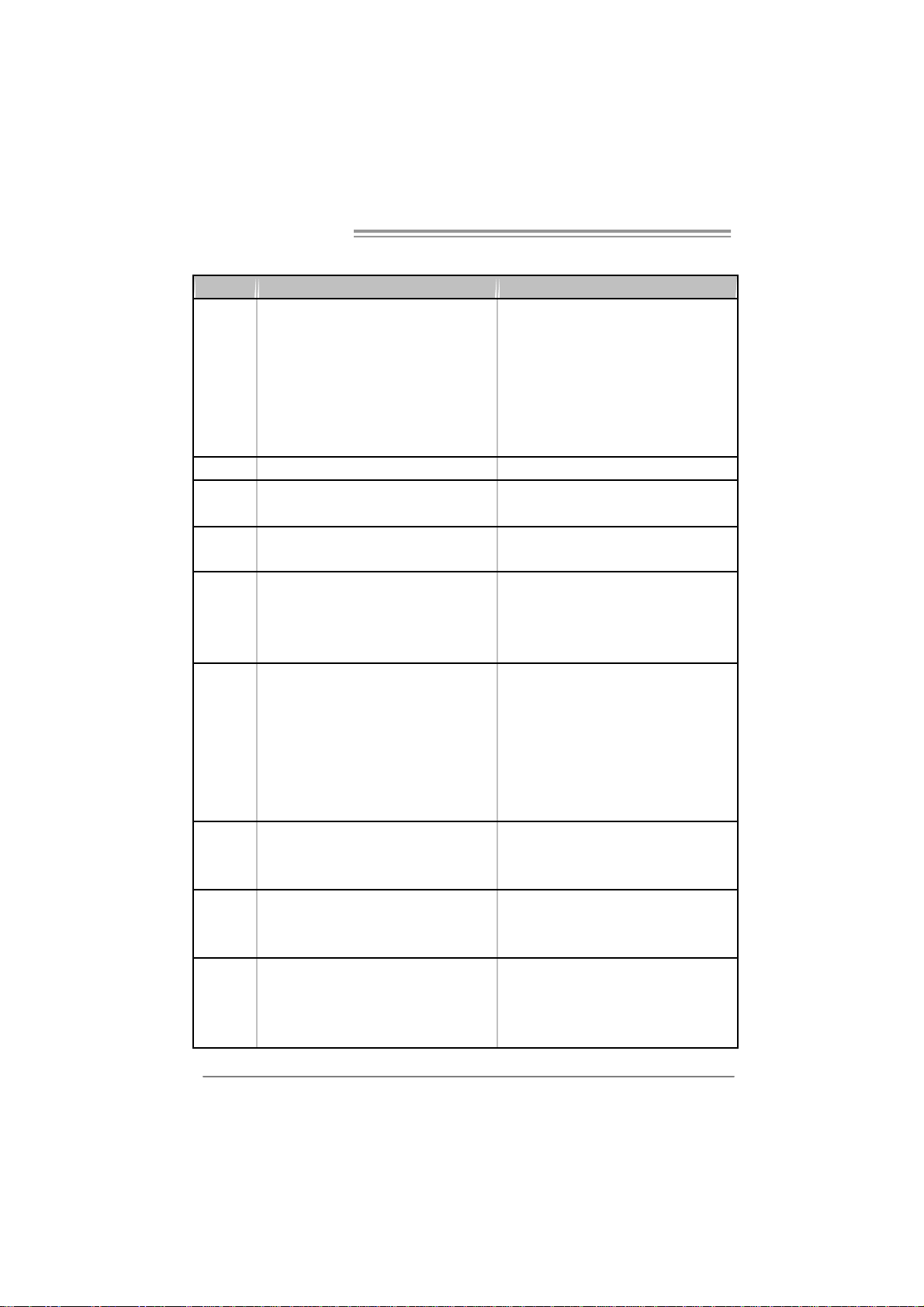
1.4 REAR PANEL CONNECTORS (FOR VER 6.X)
PS/2
Mou se
PS/2
Keyboard
COM1 USBX2USBX2
VGA1
LAN
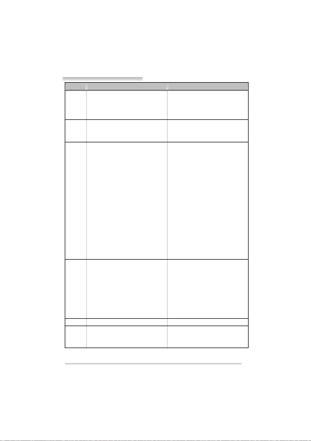
1.5 REAR PANEL CONNECTORS (FOR VER 5.X)
PS /2
Mouse
LA N
Lin e I n/
Surround
Line Out
M ic In 1 /
Bass/ Cen ter
P S/2
Keyboar d
COM1 USBX2USBX2
Center
Rear
Sid e
VGA1
Line In
Line Out
Mi c In
Since t he audio c hip s up ports Hig h Defini ti on A udio Specific ation, the func ti on of eac h audi o
jack can be d efine d b y sof tware. T he inpu t / out put fu nctio n o f e ach audi o jac k l is ted above
represents t he def ault s etti ng . Howe ver, wh en c onnecti ng exter nal micr ophon e to t he audio
port, pleas e us e the Li n e I n (bl ue) an d Mi c In ( Pin k) a udio j ac k.
4
Page 7
945G Micro 775 TE / 945GC Micro 775
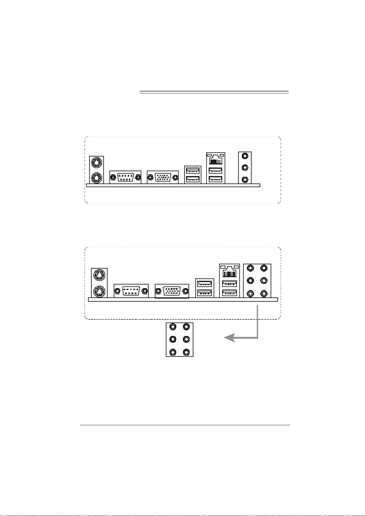
1.6 MOTHERBOARD LAYOUT (FOR VER 6.X)
JKBMS1
JAT XPW R 2
C
O
J
M
C
1
O
M
1
JKBV1
LGA775
CP U 1
JVGA1
JPRNT1
JUSB V1
JUSB2
JC FAN1
JRJ45USB1
Super
I/ O
AUDI O1
Code c
JA U DI O F1
J SPD I F_OU T
LAN
PEX1 _1
JCDIN1
PE X16_1
BIOS
JS PDIF_IN( optional)
PCI1
PCI 2
Note: ■ represents the 1st pin.
Intel
945G
or
945GC
J U SBV3_ 1
JUSB3
Intel
ICH7
JUSB4
JATX PW R1
DDR 2_A 1
DDR 2_B 1
FD D1
ID E1
JCMOS1
JCI1
(opti onal)
BA T1
J PANEL 1
JS F AN 1
SATA1SATA3
SATA2SA TA4
5
Page 8

Motherboard Manual
1.7 MOTHERBOARD LAYOUT (FOR VER 5.X)
JKBMS1
JAT XPW R 2
COM1JCOM1
JKBV1
JVGA1
JUSB2
JRJ45USB1
JA U D I O 2
Code c
JPRNT1
JUSB V1
JA U DI O F1
J SPD I F_OU T
LAN
Super
JCDIN1
I/ O
PEX1 _1
LGA775
JC FAN1
PE X16_1
BIOS
JS PDIF_IN( optional)
PCI1
PCI 2
Note: ■ represents the 1st pin.
CP U 1
Intel
945G
or
945GC
J U SBV3_ 1
JUSB3
Intel
ICH7
JUSB4
JATX PW R1
DDR 2_A 1
DDR 2_B 1
FD D1
ID E1
JCMOS1
JCI1
(opti onal)
BA T1
J PAN EL1
JS F AN 1
SATA1SATA3
SATA2SA TA4
6
Page 9
945G Micro 775 TE / 945GC Micro 775
CHAPTER 2: HARDWARE INSTALLATION
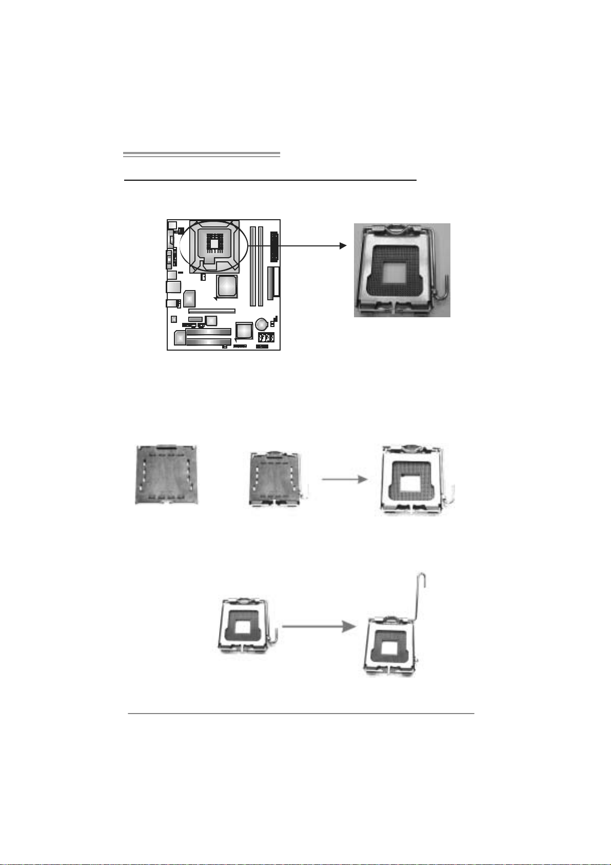
2.1 INSTALLING CENTRAL PROCESSING UNI T (CPU)
Special Notice:
Remo v e Pin Cap before installa tion, and m ake goo d preservation
for future use. When the CPU is remo ved, cov er the Pin Cap on the
empty so cket to ensure pin legs won’ t be da mag ed.
Pin-Cap
Step 1: Pull the socket locking lever out from the socket and then raise
the lever up to a 90-degree angle.
7
Page 10
Motherboard Manual
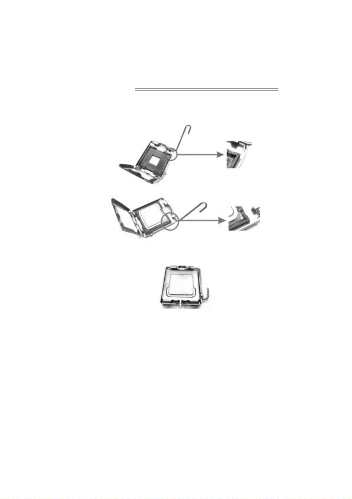
Step 2: Look for the triangular cut edge on socket, and the golden dot on
CPU should point forwards this triangular cut edge. The CPU will
fit only in the correct orientation.
Step 2-1:
Step 2-2:
Step 3: Hold the CPU down firmly, and then lower the lever to locked
position to complete the installation.
Step 4: Put the CPU Fan and heatsink assembly on the CPU and buckle it
on the retention frame. Connect the CPU FAN power cable into
the JCFAN1. This completes the installation.
8
Page 11

945G Micro 775 TE / 945GC Micro 775
2.2 FAN HEADERS
These fan headers support cooling-fans built in the computer. The fan
cable and connector may be different according to the fan manufacturer.
Connect the fan cable to the connector while matching the black wire to
pin#1.
JCFAN1: CPU Fan Header
JCFAN1
1
4
JSF AN1 : Sy stem Fan H eader
JSFAN1
1
3
Assignment
Pin
1 Ground
2 +12V
3 FAN RPM rate
sense
4 Smart Fan
Control
Pin
1 Ground
2 +12V
3 FAN RPM rate
Assignment
sense
Note:
The J CF AN1 and JSFAN1 s upport 4-pi n and 3- pin head co nnec tor . W hen co nn ecti ng
with wi res ont o c onnectors , pleas e note that t he re d wi re i s t he positi ve an d s houl d be
conn ecte d t o pi n#2, and the bl ac k wi re is Gro und a nd s hould b e c onnec t ed to GND.
9
Page 12
Motherboard Manual
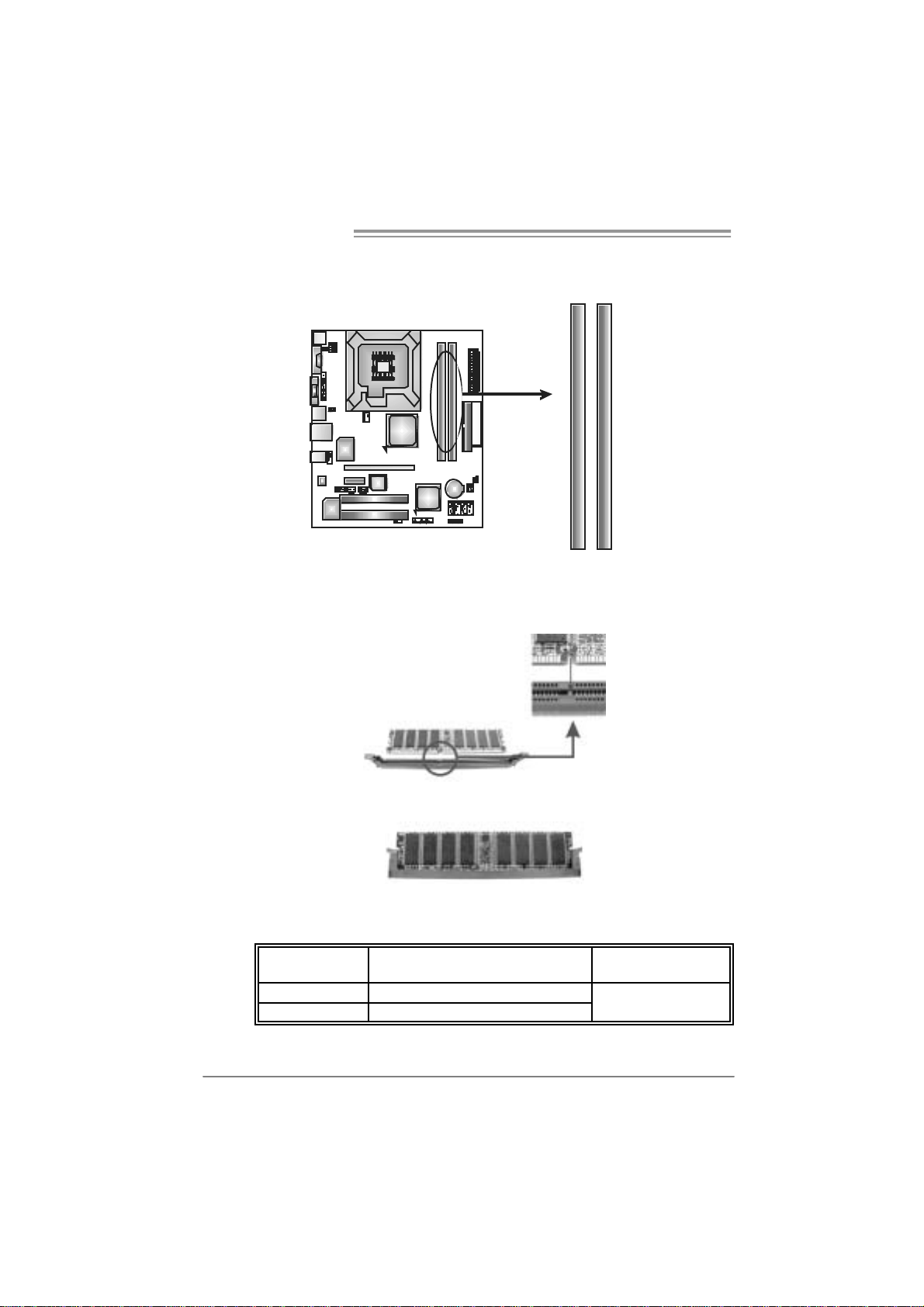
2.3 INSTALLING SYSTEM MEMORY
A . DDR2 module
DDR2_B1
DDR2_A1
1. Unlock a DIMM slot by pressing the retaining clips outward. Align a
DIMM on the slot such that the notch on the DIMM matches the
break on the Slot.
2. Insert the DIMM vertically and firmly into the slot until the retaining
chip snap back in place and the DIMM is properly seated.
B. Memory Capacity
DI MM Socket
Location
DDR2_A1 256MB/512MB/1GB *1
DDR2_B1 256MB/512MB/1GB *1
DDR2 Module Total Memory Size
Max memory 2GB.
10
Page 13
945G Micro 775 TE / 945GC Micro 775
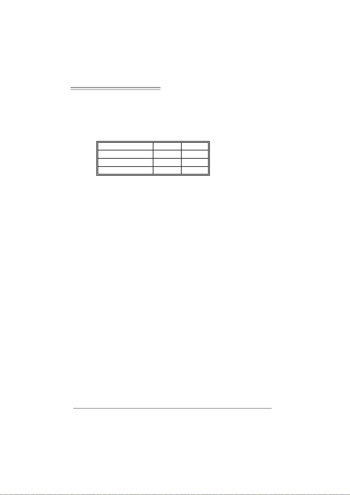
C. Dual Channe l Me mory ins tallation
To trigger the Dual Channel f unction of the motherboard, the memory module
must meet the following requirements:
Install memory module of the same density in pairs, shown in the following
table.
Du al Channel Status
Disabled O X
Disabled X O
Enabled O O
DDR2_A1
(O means memory installed, X means memory not installed.)
The DRAM bus width of the memory module must be the same (x8 or
x16)
DDR2_B1
11
Page 14
Motherboard Manual
2.4 CONNECTORS AND SLOTS
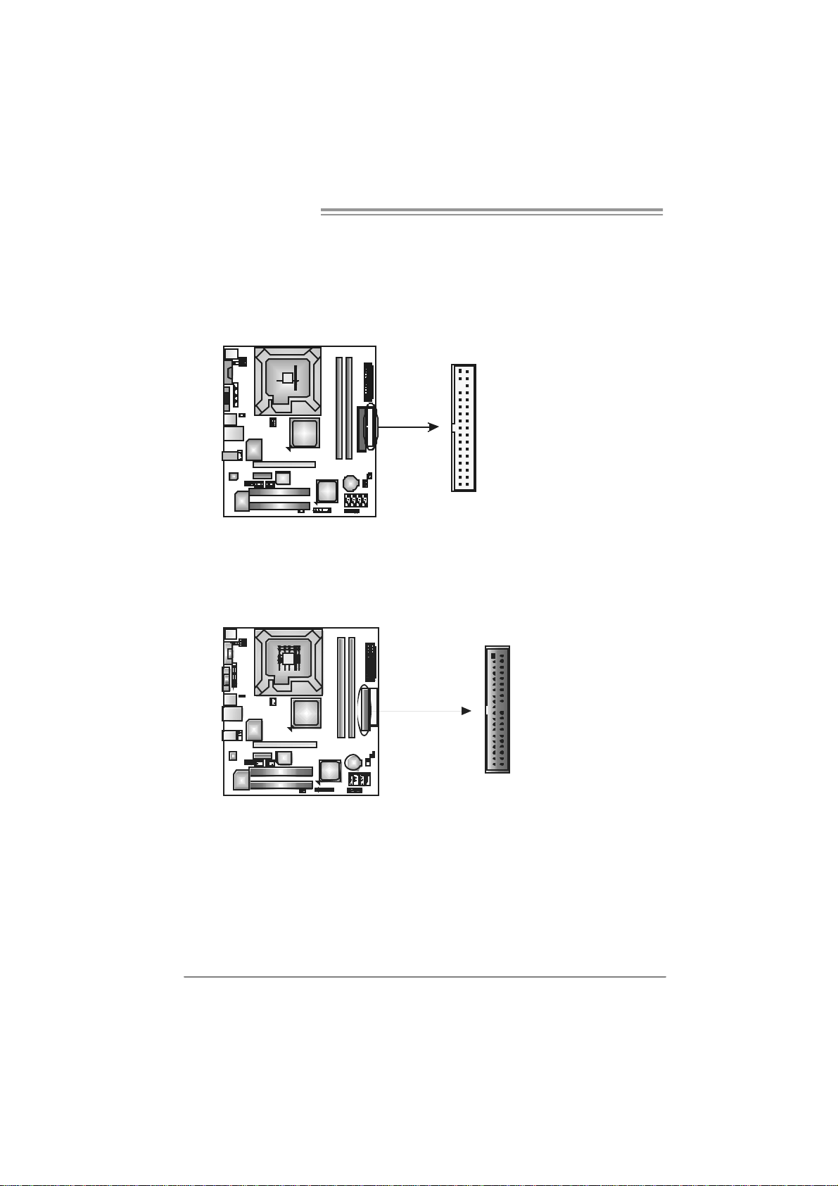
FDD1: Floppy Disk Connector
The motherboard prov ides a standard floppy disk connector that supports 360K,
720K, 1.2M, 1.44M and 2.88M floppy disk ty pes. This connector supports the
prov ided f loppy drive ribbon cables.
IDE1: Hard Disk Connecto rs
The motherboard has a 32-bit Enhanced PCI IDE Controller that prov ides PIO
Mode 0~4, Bus Master, and Ult ra DMA 33/66/100 functionality.
The IDE connector can connect a master and a slave drive, so y ou can connect
up to two hard disk driv es.
12
3433
12
2
1
40
39
Page 15
945G Micro 775 TE / 945GC Micro 775
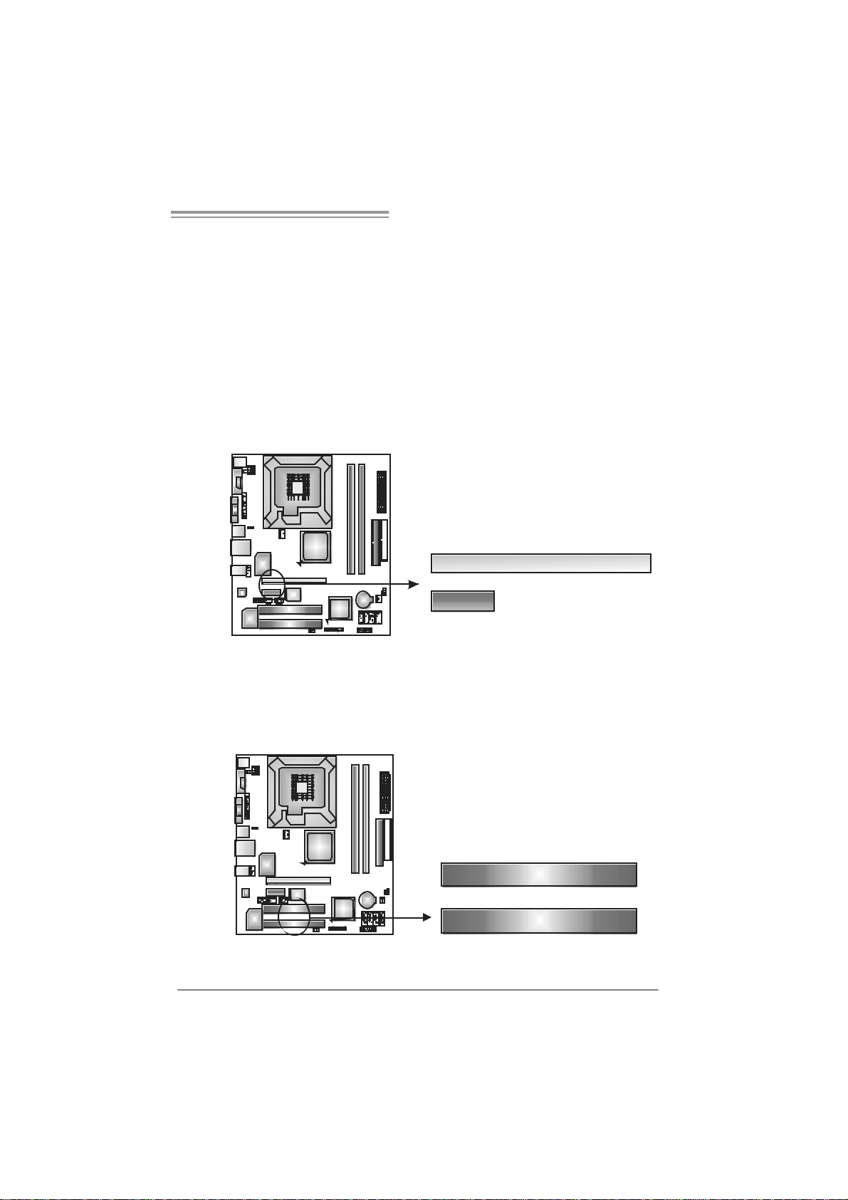
PEX16_1: PC I-Express x16 Sl ot
- PCI-Express 1.0a compliant.
- Maximum theoret ical realized bandwidth of 4GB/s simultaneously per
direction, f or an aggregat e of 8GB/s totally.
PEX1_ 1: PCI -Expres s x1 Slot
- PCI-Express 1.0a compliant.
- Data transf er bandwidth up t o 250MB/s per direction; 500MB/s in total.
- PCI-Express supports a raw bit-rate of 2.5Gb/s on the data pins.
- 2X bandwidth ov er the tradit ional PCI architecture.
PE X1 6_ 1
PE X1_ 1
PCI1~PCI2: Periphe ral Component In terconnect Slots
The motherboard is equipped with 2 standard PCI s lots. PCI stands f or
Peripheral Component Interconnect, and it is a bus st andard for expansion
cards. This PCI slot is designated as 32 bits.
PC I1
PCI2
13
Page 16
Motherboard Manual
CHAPTER 3: HE ADERS & J UMPERS SETUP
3.1 H
OW TO SET UP JUMPERS
The illustration shows how to set up jumpers. When the jumper cap is
placed on pins, the jumper is “close”, if not, that means the jumper is
“open”.
Pin opened Pin closed Pin1-2 closed
3.2 DETAIL SETT INGS
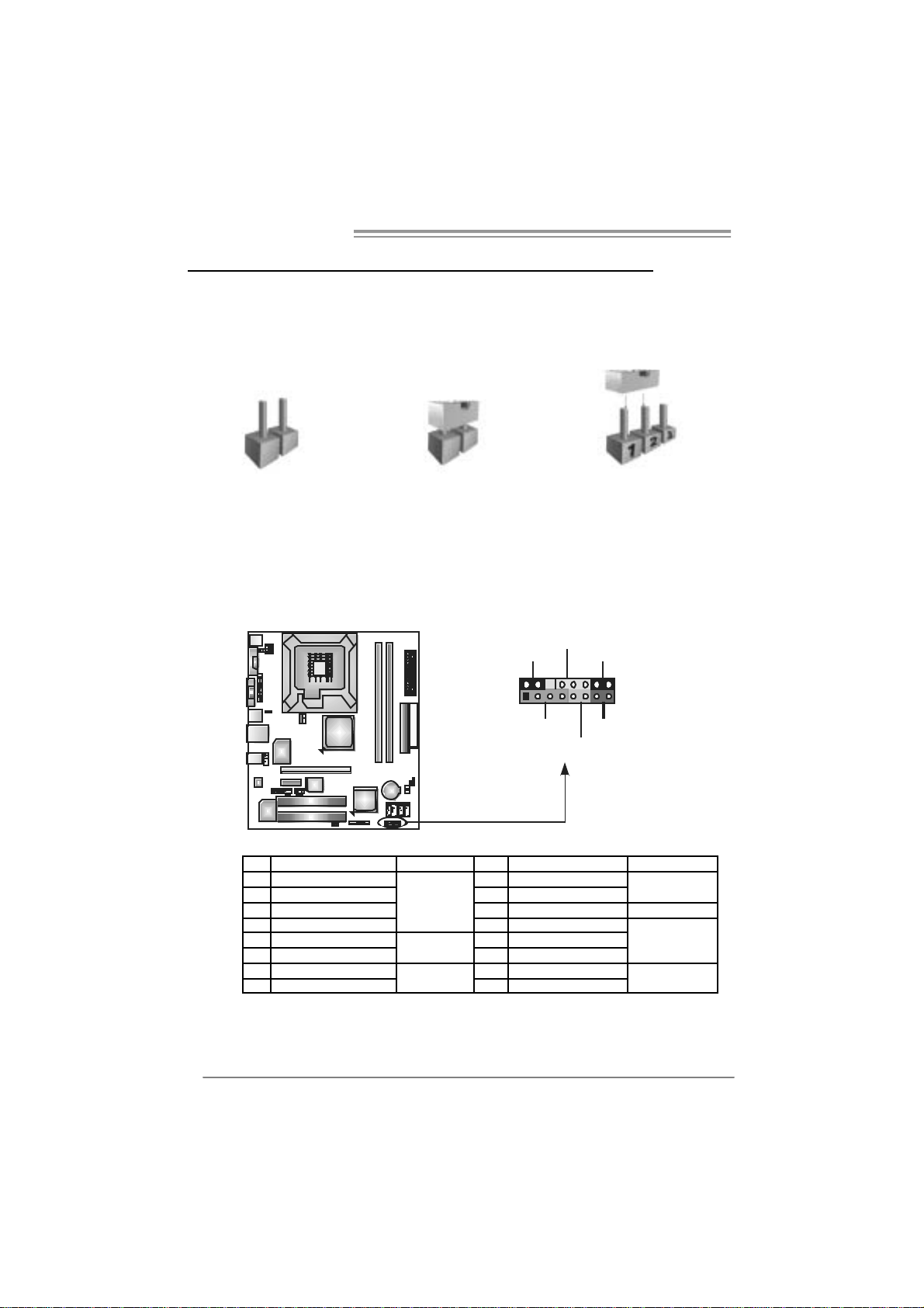
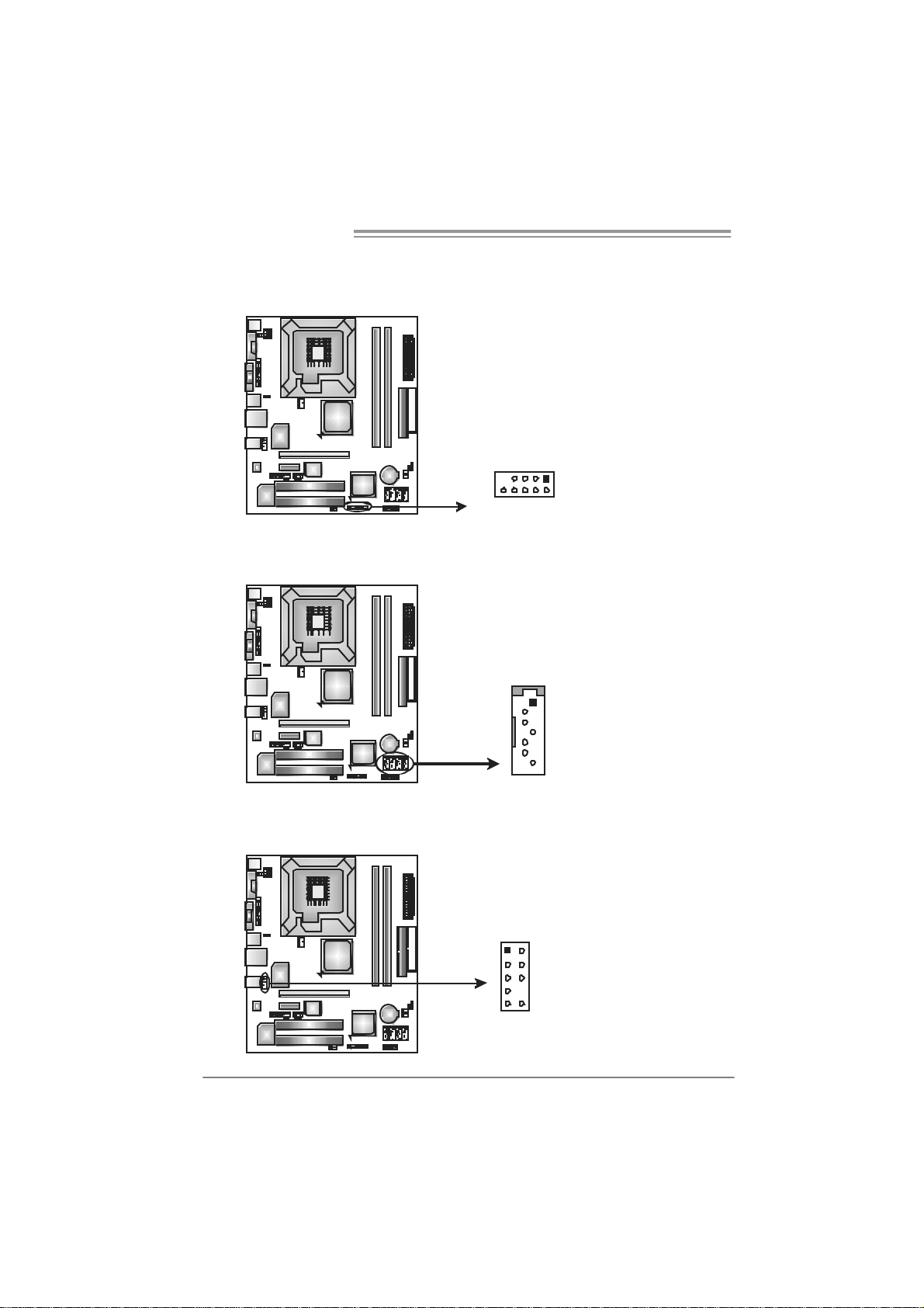
JPANEL1: Front Panel Header
This 16-pin connector includes Power-on, Reset, HDD LED, Power LED, Sleep
button, and speaker. It allows user to connect t he PC case’s front panel switch
functions.
PWR_LED
SLP
9
1
SPK
++
HLED
ON/OFF
-
-
+
RST
16
8
14
Pin Assignment Function Pin Assignment Functio n
1 +5V 9 Sleep control
2 N/A 10 Ground
3 N/A 11 N/A N/A
4 Speaker
5 HDD LED (+) 13 P ower LED (+)
6 HDD LED (-)
7 Ground 15 Power button
8 Reset control
Speaker
Connector
Hard drive
LED
Reset button
12 P ower LE D (+)
14 P ower LE D (-)
16 Ground
Sleep button
Power LED
Power-on button
Page 17
945G Micro 775 TE / 945GC Micro 775
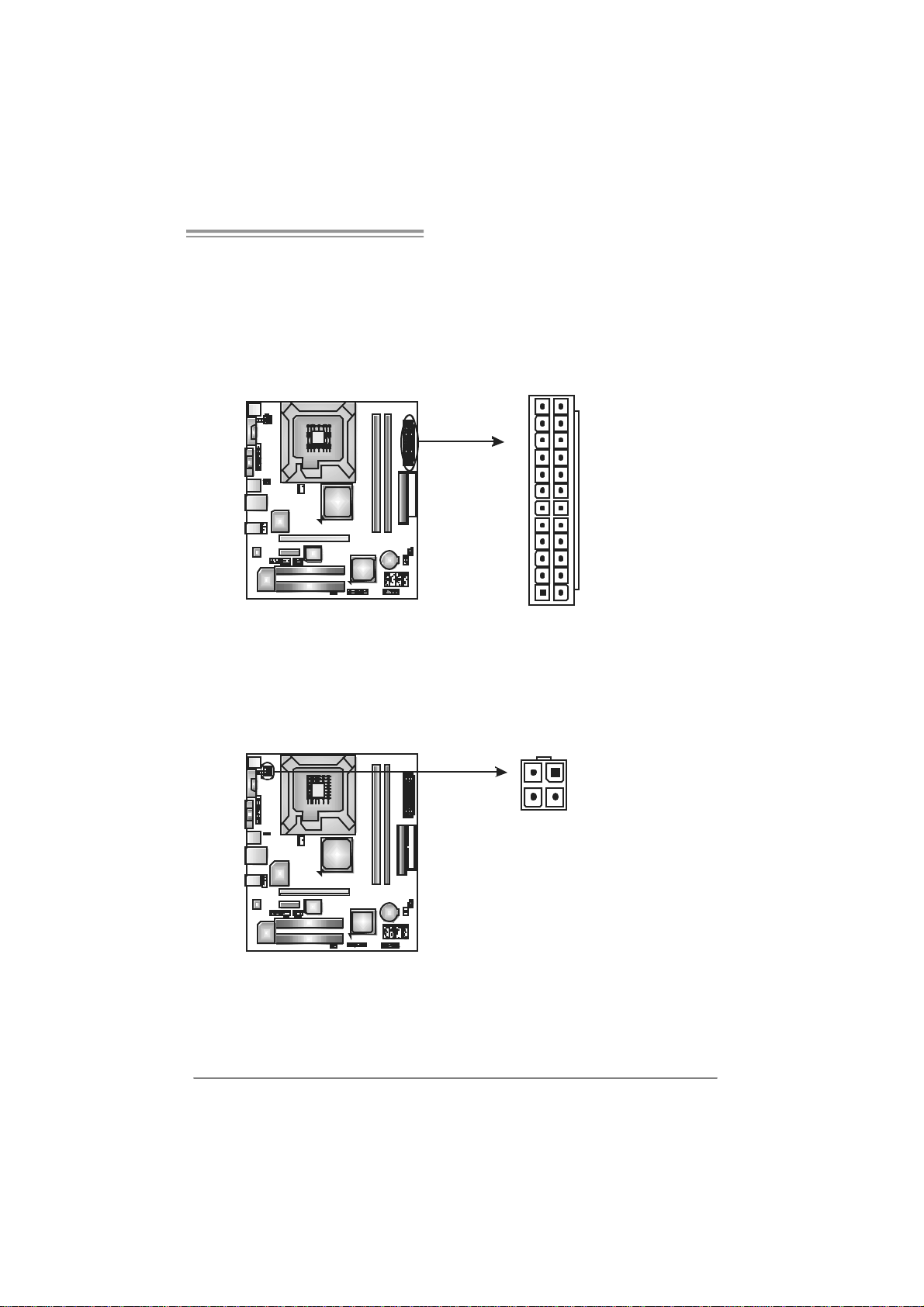
JATXPW R1: AT X Power Sou rce C o nnector
This connector allows user to connect 24-pin power c onnector on the ATX
power supply.
Pin Assignment
1 +3.3V
2 +3.3V
3 Ground
4 +5V
5 Ground
12
1
24
6 +5V
7 Ground
8 PW_OK
9 Standby
10 +12V
11 +12V
12 2 x 12 Detect
13 +3.3V
14 -12V
15 Ground
16 PS_ON
17 Ground
18 Ground
13
19 Ground
20 -5V
21 +5V
22 +5V
23 +5V
24 Ground
Voltage +5V
JATXPW R2: AT X Power Sou rce C o nnector
By connect ing this connector, it will provide +12V to CPU power circ uit.
12
3
4
Pin
1 +12V
2 +12V
3 Ground
4 Ground
Assignment
15
Page 18
Motherboard Manual
JUSB3/JUSB4: Heade rs for USB 2.0 Ports at Fron t Panel
This motherboard prov ides 2 USB 2.0 headers, which allows user to connect
additional USB cable on the PC front panel, and also can be connected with
internal USB dev ices, like USB card reader.
JUSB4JUSB3
1
9
210
S ATA1~S ATA4 : Serial ATA Co nnectors
The motherboard has a PCI to SATA Controller with 4channels SATA interf ac e, it
satisfies the SATA 2.0 spec and with transfer rate of 3Gb/s.
SATA4 SATA2
SATA3 SATA1
1
4
7
Pin Assignment
1 +5V (fused)
2 +5V (fused)
3 USB4 USB-
5 USB+
6 USB+
7 Ground
8 Ground
9 Key
10 NC
Pin Assignment
1 Ground
2 TX +
3 TX -
4 Ground
5 RX-
6 RX+
7 Ground
JAUDIOF1: Front Panel Audio Header
This header allows user to connect the front audio output cable with the PC f ront
panel. It will disable the output on back panel audio connect ors.
16
Pin Assignment
1 Mic Left in
2 Ground
3 Mic Right in
1
2
9
10
4 GPIO
5 Ri ght line in
6 Jack Sense
7 Front Sens e
8 Key
9 Left line in
10 Jack Sens e
Page 19
945G Micro 775 TE / 945GC Micro 775
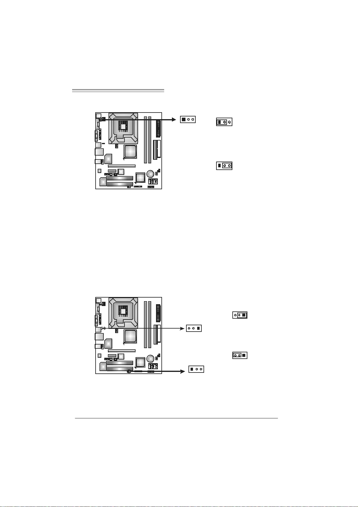
JCMOS 1: C lear CMO S H ea der
By placing the jumper on pin2-3, it allows user to restore the BIOS saf e setting
and the CMOS data, please c arefully follow the procedures to avoid damaging
the motherboard.
3
1
Pin 1-2 Close:
Normal Operation (Default).
3
1
3
1
Pin 2-3 Close:
Clear CMOS data.
※ Clear CMOS Procedures:
1. Remove AC power line.
2. Set the jumper to “Pin 2-3 close”.
3. Wait for f ive seconds.
4. Set the jumper to “Pin 1-2 close”.
5. Power on the AC.
6. Reset your desired password or clear the CMOS data.
JCI1: Chassis O pen Header (Optional)
This connector allows system t o monitor PC case open stat us. If the signal has
been triggered, it will record to the CMOS and show t he message on next
boot-up.
Pin
Assignment
1 Case open s ignal
2 Ground
2
1
17
Page 20
Motherboard Manual
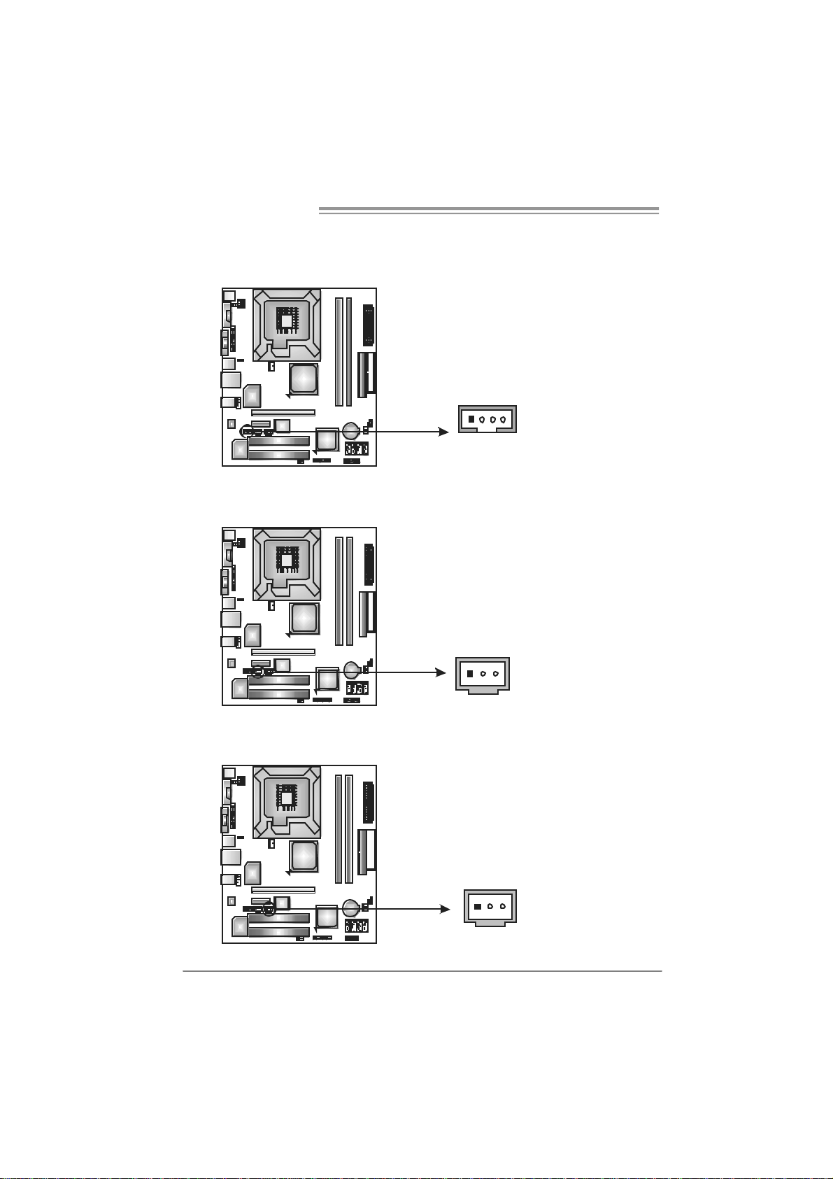
JCDIN1: CD-R OM Aud io-in Connector
This connector allows user to connect the audio s ource f rom the v ariaty devices,
like CD-ROM, DVD -ROM, PCI sound card, PCI TV turner card etc ..
JSPDIF_O U T: Digi tal Audio out Connecto rs
This connector allows user to connect the PCI brac ket SPDIF output header.
14
13
Assignment
Pin
1 Left Channel
Input
2 Ground
3 Ground
4 Right Channel
Input
Pin
Assignment
1 +5V
2 SPDIF_OUT 1
3 Ground
JSPDIF_IN: Di gital Audio in Connectors (Optio nal)
This connector allows user to connect the PCI brac ket SPDIF input header.
18
13
Pin
Assignment
1 +5V
2 SPDIF_IN1
3 Ground
Page 21
945G Micro 775 TE / 945GC Micro 775
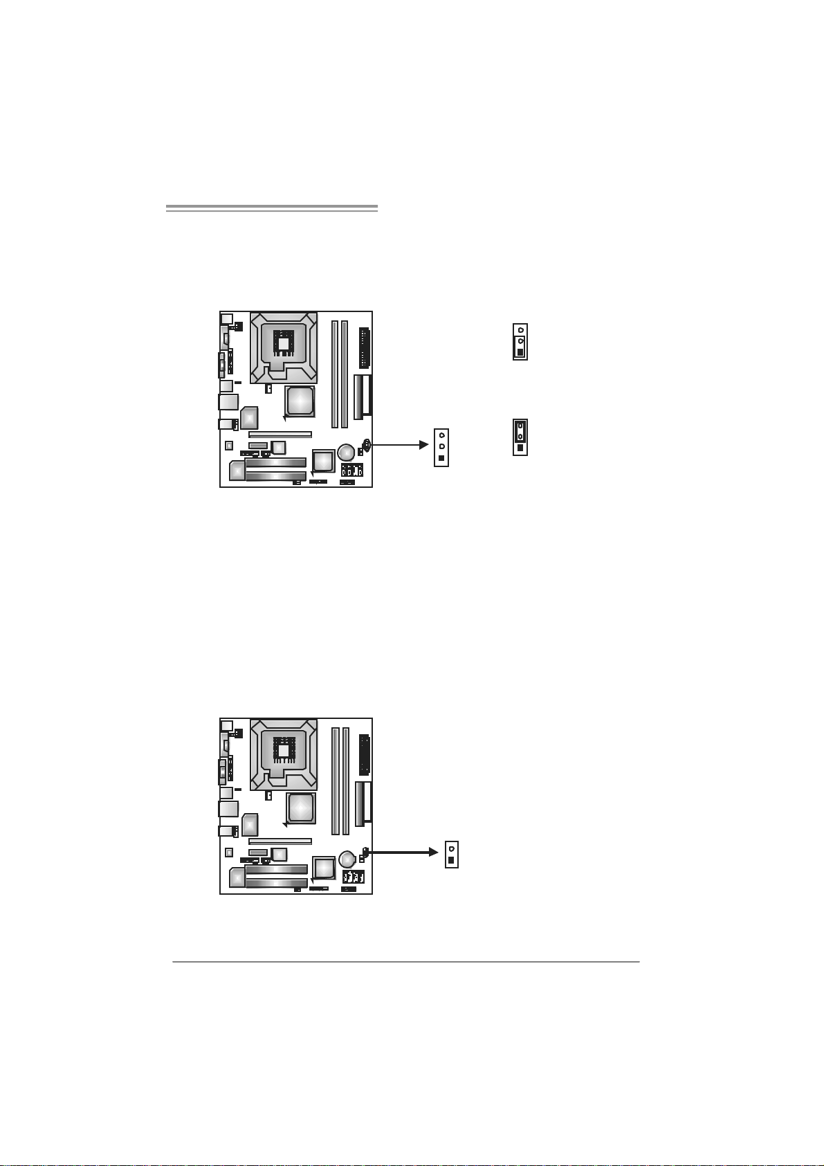
JKBV1: Power Source Heade r for PS /2 Keyboard and Mouse
31
13
Pin 1-2 Clos e
+5V for PS/2 keyboard and
mouse.
31
Pin 2-3 close
PS/2 keyboard and mouse are
powered by +5V standby
voltage.
Note:
In or der to s upport this f unc ti on “Po wer -on s ys te m vi a ke yboar d a nd mous e”, “JKBV1”
jump er cap s hould be pl ac ed on Pin 2-3.
JUSBV1/JUSBV3 _1: P ower Sour ce Heade rs for US B Ports
Pin 1- 2 Close:
JUSBV1: +5V for USB ports at JRJ 45USB1/JUSB2.
JUSBV3_1: +5V for USB ports at f ront panel (JUSB3/JUSB4).
Pin 2- 3 Close:
JUSBV1: USB ports at JRJ45U SB1/JUSB2 are powered by +5V standby
v oltage.
JUSBV3_1: USB ports at front panel (JUSB3/JUSB4) are powered by +5V
standby v oltage.
13
JUSBV1
13
JUSBV3_1
13
Pin 1-2 close
13
Pin 2-3 close
Note:
In or der to s upport this f unc ti on “Po wer -On s ys tem via U SB devic e,” “J USB V1/
JUSBV3_1” ju mper ca p sh ould b e plac ed on Pin 2-3 indi vi duall y.
19
Page 22

Motherboard Manual
JPRNT1: Printer Port Connector
This header allows you to connector printer on the PC.
25
2
1
Pin Assignment Pin Assignment
1 -Strobe 14 Ground
2 -ALF 15 Data 6
3 Data 0 16 Ground
4 -Error 17 Data 7
5 Data 1 18 Ground
6 -Init 19 -ACK
7 Data 2 20 Ground
8 -Scltin 21 Busy
9 Data 3 22 Ground
10 Ground 23 PE
11 Data 4 24 Ground
12 Ground 25 SCLT
13 Data 5 26 Key
20
Page 23
945G Micro 775 TE / 945GC Micro 775
CHAPTER 4: USEFUL HELP
4.1 DRIVER INSTALLATION NOTE
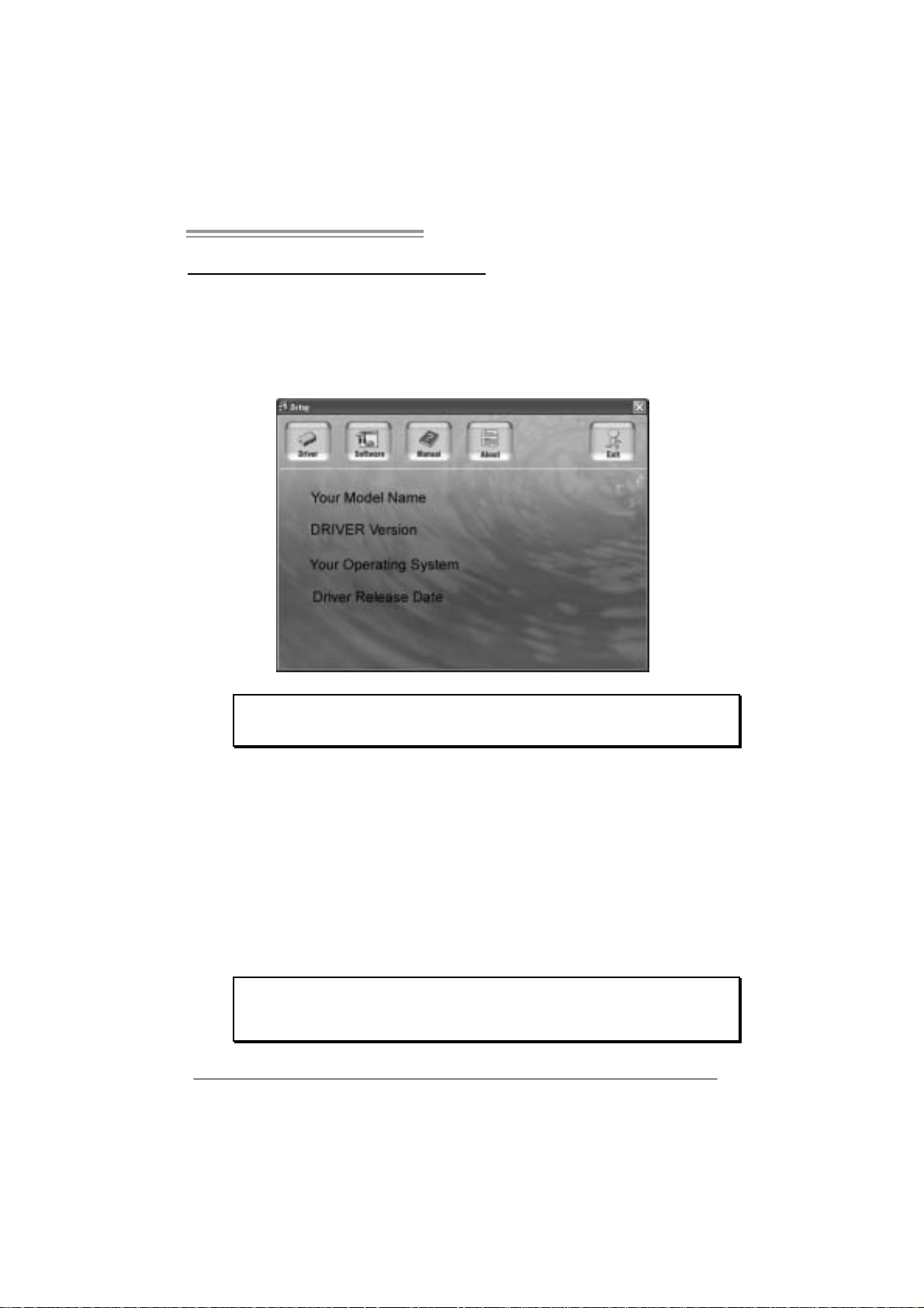
After you installed your operating system, please insert the Fully Setup
Driver CD into your optical drive and install the driver for better system
performance.
You will see the following window after you insert the CD
The setup guide will auto detect your motherboa rd and operati ng system .
Note:
If this wi n dow di dn’t sho w up after yo u ins ert the Dr iv er CD, ple ase use fi le br o ws er to
locate an d e xecute th e fi le SET U P.EXE un der yo ur o pti cal dri ve.
A. Driver Installation
To install the driver, please click on the Driver icon. The setup guide will
list the compatible driver for your motherboard and operating system.
Click on each device driver to launch the installation program.
B. Software Installation
To install the software, please click on the Software icon. The setup guide
will list the software available for your system, click on each software title
to launch the installation program.
C. Manu al
Aside from the paperback manual, we also provide manual in the Driver
CD. Click on the Manual icon to browse for available manual.
Note:
Yo u will need Acrobat Reader to open the manual file. Please downlo ad the latest version
of Acrob at Reader soft ware from
http://www.adobe.com/products/acrobat/readst ep2.html
21
Page 24

Motherboard Manual
4.2 AWARD BIOS BEEP CODE
Beep Sound Meanin g
One long beep followed by two short
beeps
High-low siren sound CPU overheat ed
One Short beep when system boot-up No error found during POST
Long beeps every other second No DRAM detected or install
Video card not found or v ideo card
memory bad
System will shut down automatically
4.3 EXTRA INFORMATION
A. BIOS Update
After you fail to update BIOS or BIOS i s invaded by virus, the
Boot-Block function will help to restore BIOS. If the following message
is shown after boot-up the system, it means the BIOS contents are
corrupted.
In this Case, please follow the procedure below to restore the BIOS:
1. Make a bootable floppy disk.
2. Download the Flash Utility “AWDFLASH.exe” from the Biostar
website: www.biostar.com.tw
3. Confirm motherboard model and download the respectively BIOS
from Biostar website.
4. Copy “AWDFLASH.exe” and respectively BIOS into floppy disk.
5. Insert the bootable disk into floppy drive and press Enter.
6. Syste m will boot-up to DOS prompt.
7. Type “Awdflash xxxx.bf/ sn/py/ r” in DOS prompt.
(xxxx means BIOS name.)
8. Syste m will update BIOS automatically and restart.
9. The BIOS has been recovered and will wo rk p roperly.
22
Page 25

945G Micro 775 TE / 945GC Micro 775
B. CPU Overheated
If the system shutdown automatically after power on system for
seconds, that means the CPU protection function has been activated.
When the CPU is over heated, the motherboard will shutdown
automatically to avoid a damage of the CPU, and the system may not
power on again.
In this case, please double check:
1. The CPU cooler surface is placed evenly with the CPU surface.
2. CPU fan is rotated normally.
3. CPU fan speed is fulfilling with the CPU speed.
After confirmed, please follow steps below to relief the CPU
0protection function.
1. Remove the power cord from power supply for seconds.
2 . Wa i t fo r second s.
3. Plug in the power cord and boot up the system.
Or you can:
1. Clear the CMOS data.
(See “Close CMOS Header: JCMOS1” section)
2 . Wa i t fo r second s.
3. Po we r on th e syste m ag ai n.
23
Page 26

Motherboard Manual
e
4.4 TROUBLESHOOTING
Probable Solution
1. No power to the system at all
Power light don’t illuminate, fan
inside power supply does not turn
on.
2. Indicator light on key board does
not turn on.
System inoperativ e. Keyboard lights
are on, power indicator lights are lit,
and hard driv e is spinning.
System does not boot from hard disk
driv e, can be booted f rom optical driv e.
System only boots f rom optical drive.
Hard disk can be read and applic ations
can be used but booting from hard dis k
is impossible.
Screen mess age says “Invalid
Configuration” or “CMOS Failure.”
Cannot boot system after installing
second hard driv e.
1. Make sure power cable is
securely plugged in.
2. Replace cable.
3. Contact tec hnical support.
Using even pressure on both ends of
the DIMM, press down firmly until the
module snaps into place.
1. Check cable running from disk to
disk cont roller board. Mak e sure
both ends are securely plugged
in; c h ec k t h e driv e ty p e in t he
standard CMOS setup.
2. Backing up the hard drive is
extremely import ant. All hard
disks are capable of breaking
down at any time.
1. Back up data and applications
files.
2. Ref ormat the hard driv e.
Re-install applic ations and data
using backup disks.
Review system’s equipment. Make s ur
correct inf ormation is in setup.
1. Set master/slave jumpers
correctly.
2. Run SETUP program and select
correct driv e types. C all the drive
manufact urers for compatibility
with other drives.
24
Page 27

945G Micro 775 TE / 945GC Micro 775
CHAPTER 5: WARPSPEEDER™
5.1 INTRODUCTION
[WarpSpeeder™], a new powerful control utility, features three
user-friendly functions including Overclock Manager, Overvoltage
Manager, and Hardware Monitor.
With the Overclock Manager, users can easily adjust the frequency they
prefer or they can get the best CPU performance with just one click. The
Overvoltage Manager, on the other hand, helps to power up CPU core
voltage and Memory voltage. The cool Hardware Monitor smartly indicates
the temperatures, voltage and CPU fan speed as well as the chipset
information. Also, in the About panel, you can get detail descriptions about
BIOS model and chipsets. In addition, the frequency status of CPU,
memory, AGP and PCI along with the CPU speed are synchronically
shown on our main panel.
Moreover, to protect users' computer systems if the setting is not
appropriate when testing and results in system fail or hang,
[WarpSpeeder™] technology assures the system stability by automatically
rebooting the computer and then restart to a speed that is either the
original system speed or a suitable one.
5.2 SYS TEM REQUIREMENT
OS Support: Windows 98 SE, Windows Me, Windows 2000, Windows XP
DirectX: DirectX 8.1 or above. (The Windows XP operating system
includes DirectX 8.1. If you use Windows XP, you do not need to install
DirectX 8.1.)
25
Page 28

Motherboard Manual
5.3 INSTALLATION
1. Execute the setup execution file, and then the following dialog will pop
up. Please click “Next” button and follow the default procedure to
install.
2. When you see the following dialog in setup procedure, it means setup
is completed. If the “Launch the WarpSpeeder Tray Utility” checkbox
is ch ecked, the Tray Icon utility and [WarpSpeede r™] utility will be
automatically and immediately launched after you click “Finish”
button.
26
Usage :
The following figures are just only for reference, the screen printed in
this user manual will change acco rding to yo ur m oth erboard on hand.
Page 29

945G Micro 775 TE / 945GC Micro 775
5.4 WARPSPEEDER™
1. Tray Icon:
Whenever the Tray Icon utility is launched, it will display a li ttle tray
icon on the right side of Windows Taskbar.
This utility is responsible for conveniently invoking [WarpSpeeder™]
Utility. You can use the mouse by clicking the left button in order to
invoke [WarpSpeeder™] directly from the little tray icon or you can
right-click the little tray icon to pop up a popup menu as following
figure. The “Launch Utility” item in the popup menu has the same
function as mouse l eft-click on tray icon and “Exit” i tem will cl ose
Tray Icon utility if selected.
27
Page 30

Motherboard Manual
2. Main Panel
If you cli ck the tray icon, [WarpSpeeder™] util ity will be i nvoked.
Please refer to the following figure; the utility’s first window you wi ll
see is Main Panel.
Main Pane l contains features as follows:
a . Di sp l a y t he CPU Sp ee d , C P U e x t e r nal cl o c k, Mem o ry clo c k, AGP cl o ck,
and PCI clock information.
b. Contains About, Voltage, Overclock, and Hardware Monitor Buttons for
invoking respective panels.
c. With a user-friendly Status Animation, it can represent 3 overclock
percentage stages:
Man walking→overclock percentage from 100% ~ 110 %
Panther running→overclock percentage from 110% ~ 120%
Car racing →overclock percentage from 120% ~ above
28
Page 31

945G Micro 775 TE / 945GC Micro 775
3. Voltage Panel
Click the Vol tage button in Main Panel, th e button will be hi ghlighted
an d the Voltage Panel will slide out to up as the followi ng figure.
In this panel, you can decide to increase CPU core voltage and
Memory voltage or not. The default setting is “No”. If you want to get
the best performance of overclocking, we recommend you click the
option “Yes”.
29
Page 32

Motherboard Manual
4. Over clock Panel
Click the Overcl ock button in Main Panel, the button will be
highlighted and the Overclock Panel will slide out to left as the
following figure.
Overclock Panel cont ains the these fea tures:
a. “–3MHz button”, “-1MHz button”, “+1MHz button”, and “+3MHz button”:
provide user the ability to do real-time overclock adjustment.
Warning:
Manually overc lock is potentially dangerous, especially when the
ov erclocking percentage is over 110 %. We s trongly recommend you
v erif y ev ery speed you overclock by click the Verify button. Or, you can
just click Auto overclock button and let [WarpSpeeder™] automatically
gets the best result f or y ou.
b. “Recovery Dialog button”: Pop up the following dialog. Let user select
a restoring way if system need to do a fail-safe reboot.
30
Page 33

945G Micro 775 TE / 945GC Micro 775
c. “Auto-overclock button”: User can click this button and
[WarpSpeeder™] will set the best and stable perfo rman ce and
frequency automatically. [WarpSpeeder™] utility will execute a
se ries of testing until syste m fail. Th en system will do fail -safe
reboot by using Watchdog function. After reboot, the
[WarpSpeeder™] utility will restore to the hardware default
setting or load the verified best and stable frequency according
to the Recovery Dialog’s setting.
d. “Verify button”: User can click this button and [WarpSpeeder™]
will proceed a testing for current frequency. If the testing is ok,
then the current frequency will be saved into system registry. If
the testing fail, system will do a fail-safe rebooting. After reboot,
the [WarpSpeeder™] uti li ty will restore to the hardware defau lt
setting or load the verified best and stable frequency according
to the Recovery Dialog’s setting.
Note:
Because the testing programs, invoked in Aut o-overclock and Verify,
include DirectDraw, Direct3D and DirectShow tests, the DirectX 8.1 or
newer runtime library is required. And pleas e make sure y our display
card’s color depth is High c olor (16 bit ) or True color( 24/32 bit ) that is
required f or Direct3D rendering.
5. Hardware Monitor Panel
Click the Hardware Monitor button in Main Panel, the butto n will be
highlighted and the Hardware Monitor panel will slide out to left as
the following figure.
In this panel, you can get the real-time status information of your
sy stem. T he information will be refreshed every 1 second.
31
Page 34

Motherboard Manual
6. About Panel
Click the “about” button in Main Panel, the button will be highlighted
and the About Panel will slide out to up as the following figure.
In this panel, you can get model name and detail information in hints
of all the chipset that are related to overclocking. You can also get
the mainboard’s BIOS model and the Version number of
[WarpSpeeder™] utility.
32
Note:
Because the overclock, overvoltage, and hardware monitor features
are controlled by several separate chipset, [WarpSpeeder™] divide
these features to separate panels. If one chipset is not on board, the
co rrelati ve b utton in Main panel will be disabl ed, bu t will no t i nterfe re
other panels’ functions. This property can make [WarpSpeeder™]
utili ty more ro bust.
Page 35

945G Micro 775 TE / 945GC Micro 775
This page is intentionally left blank.
33
Page 36

Motherboard Manual
APPENDENCIES: SPEC IN OTHER L ANGUAGE
GERMAN
945 G Micro 775 T E 945GC Micr o 775
LGA 775
Intel Core2Duo / Pentium 4 / Pentium D /
Celeron D Prozessoren mit bis zu 3,8 GHz
CPU
FSB 533 / 800 / 1066 MHz 533 / 800 MHz
Chipsatz
Grafi k
Super E/A
Arbeitsspeic h
er
IDE
SA TA
LAN
Unterstützt Hyper-Threading
Execute Disable Bit
Enhanced Intel SpeedS tep®
Extended Mem ory 64 Technology
Int el 945G
Intel ICH7
Int el GMA 950
Max. 192MB gemeinsam benut zter
Videospeicher
ITE 8712F
Hardware-Überwachung
Lüfterdrehzahl-Controller
"Smart Guardian"-Funktion von I TE
DDR2 DIMM -Steckplätze x 2
Jeder DI MM unterstützt 256/512MB & 1GB
DDR2
M ax. 2GB Arbeitss peic her
Dual-Kanal DDR2 Speic hermodul
Unt erstüt zt DDR 2 400 / 533 / 667
registrierte DIMMs. ECC DIMMs werden nicht
unterstützt .
Integrierter IDE-Controller
Ultra DM A 33 / 66 / 100 Bus Mas ter -M odus
Unterstützt PIO-Modus 0~4
I nt e gr i ert e r S e ri al ATA - Con tr o ll e r
Datentransferrate bis zu 3Gb/s
Konform mit der SATA-Spezifikation Version 2.0
Realtek RTL 8100C / RTL 8110SC(opt ional)
10 / 100 / 1000 M b/s Auto-Negotiation
(Gigabit-Bandbreite nur beim RTL 8110SC)
Halb-/ Vollduplex-Funktion
34
LGA 775
Intel Core2Duo / Pentium 4 / Pentium D /
Celeron D Prozessoren mit bis zu 3,8 GHz
Unterstützt Hyper-Threading
Execute Disable Bit
Enhanced Intel SpeedS tep®
Extended Mem ory 64 Technology
Int el 945GC
Intel ICH7
Int el GMA 950
Max. 192MB gemeinsam benut zter
Videospeicher
ITE 8712F
Hardware-Überwachung
Lüfterdrehzahl-Controller
"Smart Guardian"-Funktion von I TE
DDR2 DIMM -Steckplätze x 2
Jeder DI MM unterstützt 256/512MB & 1GB
DDR2
M ax. 2GB Arbeitss peic her
Dual-Kanal DDR2 Speic hermodul
Unt erstüt zt DDR 2 400 / 533
registrierte DIMMs. ECC DIMMs werden nicht
unterstützt .
Integrierter IDE-Controller
Ultra DM A 33 / 66 / 100 Bus Mas ter -M odus
Unterstützt PIO-Modus 0~4
I nt e gr i ert e r S e ri al ATA - Con tr o ll e r
Datentransferrate bis zu 3Gb/s
Konform mit der SATA-Spezifikation Version 2.0
Realtek RTL 8100C / RTL 8110SC(opt ional)
10 / 100 / 1000 M b/s Auto-Negotiation
(Gigabit-Bandbreite nur beim RTL 8110SC)
Halb-/ Vollduplex-Funktion
Page 37

945G Micro 775 TE / 945GC Micro 775
945 G Micro 775 T E 945GC Micr o 775
ALC861VD(VER 6.X) / ALC 888(V ER 5.X)
5.1-Kanal -A udioausgabe (VER 6. X)
7.1-Kanal -A udioausgabe (VER 5. X)
Unterstützt High-Definition Audio
PS/2-Tastatur x1
PS/2-Maus x1
Serie ller A nschl uss x1
VGA-Anschluss x1
LAN-A nsc hl uss x 1
US B-A nschl uss x4
Audioanschluss (Ver 6.x) x3
Audioanschluss (Ver 5.x) x6
Wi ndows 2000 / XP / V IS TA
Biostar behält sich das Recht vor, ohne
Ankündigung die Unterstütz ung für ein
Betriebssystem hinzuz ufügen oder z u
entfernen.
Audio-Codec
Steckplätze
Onboard-Ans
chluss
Rückseiten-E
/A
Platinengröße
.
OS-Unterstüt
zung
ALC861VD(VER 6.X) / ALC 888(V ER 5.X)
5.1-Kanal -A udioausgabe (VER 6. X)
7.1-Kanal -A udioausgabe (VER 5. X)
Unterstützt High-Definition Audio
PCI Express x16 Steckplatz x1 PCI Express x16 Steckplatz x1
PCI Express x 1-Steckplatz x1 PCI Express x 1-Stec kplatz x1
PCI-Steckplatz x2 PCI-Steckplatz x2
Diskettenlaufwe rkansc hluss x 1 Diskettenlaufwe rkansc hluss x 1
IDE-A nschl uss x1 IDE-A nschl uss x1
Drucke ra nsc hl uss Anschluss x1 Dr uc keransc hluss Anschluss x1
SATA-Anschluss x4 SATA-Anschluss x4
Fronttafelanschluss x1 Fronttafelanschluss x1
Fr ont-Audi oansc hluss x1 Fr ont-Audi oansc hluss x1
CD-I N- Ansc hluss x1 CD-I N- Ansc hluss x1
S/PDIF-Ausgangsanschluss x1 S/PDIF-Ausgangsanschluss x1
S/PDIF Eingangsanschluss(optional) x1 S /PDIF Eingangsanschluss(optional) x1
CPU-Lüfter-Sockel x1 CPU-Lüfter-Sockel x1
System-Lüfter-Sockel x1 System-Lüfter-Sockel x1
"Gehäuse offen"-Sockel (optional) x1 "Gehäuse offen"-Sockel (optional) x1
"CMOS lösc hen"-S oc kel x1 "CMOS lösc hen"-Sockel x1
US B-A nschl uss x2 US B-A nschl uss x2
Stromanschluss (24-polig) x1 Stromanschluss (24-polig) x1
Stromanschluss (4-polig) x1 Stromanschluss (4-polig) x1
PS/2-Tastatur x1
PS/2-Maus x1
Serie ller A nschl uss x1
VGA-Anschluss x1
LAN-A nsc hl uss x 1
US B-A nschl uss x4
Audioanschluss (Ver 6.x) x3
Audioanschluss (Ver 5.x) x6
219 mm (B) X 235 mm (L) 219 m m (B) X 235 m m (L)
Wi ndows 2000 / XP / V IS TA
Biostar behält sich das Recht vor, ohne
Ankündigung die Unterstütz ung für ein
Betriebssystem hinzuz ufügen oder z u
entfernen.
35
Page 38

Motherboard Manual
FRANCE
945G Micro 775 T E 945GC Micro 7 75
LGA 775
Processeurs Intel Core2Duo / Pentium 4 /
Pentium D / Celeron D jusqu'à 3, 4 GHz
UC
Bus fr ontal 533 / 800 / 1066 M Hz 533 / 800 MHz
Chipset
Graphiques
Super E/S
Mémoire
princi pale
IDE
SA TA
LAN
Prend en charge les technologies
Hyper-Threading
d'exécuti on de bit de désactivation
Intel SpeedSt ep® optimisée
de mémoire ét endue 64
Int el 945G
Intel ICH7
Int el GMA 950
Mémoire vidéo partagée maximale de 192 Mo
ITE 8712F
Monit eur de matériel
Contr ôleur de vitess e de vent ilat eur
Fonction "Gardien intelligent" de l'ITE
Fentes DDR2 DIMM x 2
Chaque DIMM prend en charge des DDR2 de
256/512 Mo et 1Go
Capacité mémoire maximale de 2 Go
Modul e de mémoire DDR2 à mode à double voi e
Prend en c harge la DDR 2 400 / 533 / 667
Les DIMM à registres et DIMM avec code
corr ec teurs d'erreurs ne sont pas prises en
charge
Contrôleur IDE intégré
Mode princ ipale de Bus Ultra DMA 33 / 66 / 100
Prend en c harge le mode PIO 0~4,
Cont r ôl eur Se rial ATA intégré :
Taux de transfert jusqu'à 3 Go/s.
Conforme à la spécification SATA Version 2.0
Realtek RTL 8100C / RTL 8110SC(opt ional)
10 / 100 / 1000 M b/s négociat ion automatique
(La bande passante Gigabit est pour le RTL
8110SC uniquement)
Half / Full duplex capability
LGA 775
Processeurs Intel Core2Duo / Pentium 4 /
Pentium D / Celeron D jusqu'à 3, 4 GHz
Prend en charge les technologies
Hyper-Threading
d'exécuti on de bit de désactivation
Intel SpeedSt ep® optimisée
de mémoire ét endue 64
Int el 945GC
Intel ICH7
Int el GMA 950
Mémoire vidéo partagée maximale de 192 Mo
ITE 8712F
Monit eur de matériel
Contr ôleur de vitess e de vent ilat eur
Fonction "Gardien intelligent" de l'ITE
Fentes DDR2 DIMM x 2
Chaque DIMM prend en charge des DDR2 de
256/512 Mo et 1Go
Capacité mémoire maximale de 2 Go
Modul e de mémoire DDR2 à mode à double voi e
Prend en c harge la DDR 2 400 / 533
Les DIMM à registres et DIMM avec code
corr ec teurs d'erreurs ne sont pas prises en
charge
Contrôleur IDE intégré
Mode princ ipale de Bus Ultra DMA 33 / 66 / 100
Prend en c harge le mode PIO 0~4,
Cont r ôl eur Se rial ATA intégré :
Taux de transfert jusqu'à 3 Go/s.
Conforme à la spécification SATA Version 2.0
Realtek RTL 8100C / RTL 8110SC(opt ional)
10 / 100 / 1000 M b/s négociat ion automatique
(La bande passante Gigabit est pour le RTL
8110SC uniquement)
Half / Full duplex capability
36
Page 39

945G Micro 775 TE / 945GC Micro 775
945G Micro 775 T E 945GC Micro 7 75
ALC861VD(VER 6.X) / ALC 888(V ER 5.X)
Sortie audio à 5. 1 voies (VER 6.X)
Sortie audio à 7. 1 voies (VER 5.X)
Prise en charge de l'audio haute définition
Embase d' ouverture de c hâssis x1
(optional)
Clavier PS/2 x1
Souris PS/2 x1
Port série x1
Port VGA x1
Port LAN x1
Port USB x4
Fiche audio (Ver 6. x) x3
Fiche audio (Ver 5. x) x6
Wi ndows 2000 / XP / V IS TA
Biostar se réserve le droit d'ajouter ou de
supprimer le support de SE avec ou sans préavis.
Codec audio
Connecteur
embarqué
E/S du
panneau
arrière
Dim ensions
de la carte
Support SE
ALC861VD(VER 6.X) / ALC 888(V ER 5.X)
Sortie audio à 5. 1 voies (VER 6.X)
Sortie audio à 7. 1 voies (VER 5.X)
Prise en charge de l'audio haute définition
PCI Express x16 Steckplatz x1 PCI Express x16 Steckplatz x1
PCI Express x1 Steckplatz x1 PCI Express x1 Steckplatz x1 Fentes
Fente PCI x2 Fente PCI x2
Connecteur de disquette x1 C onnecteur de disquett e x1
Connecteur IDE x1 C onnecteur I DE x1
Connecteur de Port d'imprimante x1 Connecteur de Port d'imprimante x1
Connect eur SATA x4 Connect eur SATA x4
Connecteur du panneau avant x1 C onnecteur du panneau avant x1
Connecteur Audio du panneau avant x1 C onnecteur Audi o du panneau avant x1
Connecteur d'entrée CD x1 Connecteur d'entrée CD x1
Connecteur d'entrée S/PDIF (en option) x1 Connec teur d'entrée S/PDIF (en option) x1
Connecteur de sortie S/PDIF x1 Connecteur de sortie S/PDIF x1
Embase de ventilateur UC x1 Embase de ventilat eur UC x1
Embase de ventilateur système x1 Em bas e de ventilat eur syst ème x1
Embase d' ouverture de c hâssis x1
(optional)
Embase d'effacement CMO S x1 Em base d'effacement CMOS x1
Connecteur USB x2 C onnecteur USB x2
Connecteur d'alimentation (24 broches) x1 Connecteur d'aliment at ion (24 broches) x1
Connecteur d'aliment ation (4 broches) x1 Connecteur d'alimentation (4 broches) x1
Clavier PS/2 x1
Souris PS/2 x1
Port série x1
Port VGA x1
Port LAN x1
Port USB x4
Fiche audio (Ver 6. x) x3
Fiche audio (Ver 5. x) x6
219mm (l) X 235 mm (H) 219m m (l) X 235 mm (H)
Wi ndows 2000 / XP / V IS TA
Biostar se réserve le droit d'ajouter ou de
supprimer le support de SE avec ou sans préavis.
37
Page 40

Motherboard Manual
ITALIAN
945G Micro 775 T E 945GC Micro 7 75
LGA 77 5
Processore Intel Core2Duo / Pe ntium 4 /
Pentium D / Celeron D fino a 3.8 GHz
CPU
FS B 533 / 800 / 1066 MHz 533 / 800 MHz
Chipset
Grafica
Super I/O
Memoria
principale
IDE
SATA
LAN
Suppor to di Hyper -T hreading
Execute Dis able Bit
Enha nc ed Intel Sp eedStep®
Tecnol o gia Extended M emory 64
Int el 945G
Intel I CH7
Int el GMA 950
La memoria vi deo condi vis a m ass ima è d i 192MB
ITE 871 2F
Monitoraggio h ardware
Controller velocità ventolina
Funz ione "Sm art G uardi an" di I TE
Al loggi DIMM DDR 2 x 2
Ci as c un DIM M s up po rt a D DR 2 2 56/ 51 2MB e
1GB
Capacità massima della memori a 2GB
Modulo di memoria DDR2 a canale doppio
Supporto di DDR2 400 / 533 / 667
DIMM registrati e DIMM ECC no n son o
supportati
Controller ID E integrato
Modalità Bus Master Ultra DMA 33 / 66 /
100
Suppor to modalità PIO Mode 0-4
Controller Serial ATA integrato
Veloc it à di tras ferimento dei dati fi no a 3
Gb/s .
Compatibile specifiche SATA Versione 2.0.
Realtek RTL 8100C / RTL 8110SC(opt ional)
Negoziazione automat ic a 10 / 10 0 / 1000
Mb/s (la larghezz a di banda Gigabit è solo
per RTL 8110S C)
Capacità Half / Full Duplex
LGA 77 5
Processore Intel Core2Duo / Pe ntium 4 /
Pentium D / Celeron D fino a 3.8 GHz
Suppor to di Hyper -T hreading
Execute Dis able Bit
Enha nc ed Intel Sp eedStep®
Tecnol o gia Extended M emory 64
Int el 945GC
Intel I CH7
Int el GMA 950
La memoria vi deo condi vis a m ass ima è d i 192MB
ITE 871 2F
Monitoraggio h ardware
Controller velocità ventolina
Funz ione "Sm art G uardi an" di I TE
Al loggi DIMM DDR 2 x 2
Ci as c un DIM M s up po rt a D DR 2 2 56/ 51 2MB e
1GB
Capacità massima della memori a 2GB
Modulo di memoria DDR2 a canale doppio
Supporto di DDR2 400 / 533
DIMM registrati e DIMM ECC no n son o
supportati
Controller ID E integrato
Modalità Bus Master Ultra DMA 33 / 66 /
100
Suppor to modalità PIO Mode 0-4
Controller Serial ATA integrato
Veloc it à di tras ferimento dei dati fi no a 3
Gb/s .
Compatibile specifiche SATA Versione 2.0.
Realtek RTL 8100C / RTL 8110SC(opt ional)
Negoziazione automat ic a 10 / 10 0 / 1000
Mb/s (la larghezz a di banda Gigabit è solo
per RTL 8110S C)
Capacità Half / Full Duplex
38
Page 41

945G Micro 775 TE / 945GC Micro 775
945G Micro 775 T E 945GC Micro 7 75
ALC861VD(VER 6.X) / ALC 888(V ER 5.X)
Us cita audio 5.1 c a nali (V ER 6.X )
Us cita audio 7.1 c a nali (V ER 5.X )
Suppor to audi o High- Definition (HD )
Ta s t i er a PS / 2 x 1
Mouse PS/2 x1
Porta seriale x1
Porta VGA x1
Porta LAN x1
Porta USB x4
Connettore audio (Ver 6. x) x3
Connettore audio (Ver 5. x) x6
Windows 2000 / XP / VISTA
Biostar si riserva il diritto di aggiu ngere o
rimuovere il supporto di qualsiasi sistema
operativo se nza pre avviso.
Codec
audio
Connett ori
su scheda
I/O
pannello
posteriore
Dim ension
i scheda
Sistemi
operativi
supportati
ALC861VD(VER 6.X) / ALC 888(V ER 5.X)
Us cita audio 5.1 c a nali (V ER 6.X )
Us cita audio 7.1 c a nali (V ER 5.X )
Suppor to audi o High- Definition (HD )
Fente PCI Express x 16 x1 Fente PCI Express x 16 x1
Fente PCI Express x 1 x1 Fent e PCI Express x1 x1 Alloggi
Alloggio PCI x2 Alloggio PCI x2
Connett ore flo ppy x1 C onnet tore flo ppy x1
Connett ore IDE x1 Connett ore IDE x1
Connett ore Porta s tampa nte x1 C onnet tore Porta stam pa nte x1
Connett ore SA TA x4 Connettor e SA TA x4
Connett ore pannell o fro ntal e x1 C onnet tore pannello fro ntale x1
Connettore audio frontale x1 Connettore audio frontale x1
Connettore CD-in x1 Connettore CD-in x1
Connettore input S/PDIF (o ptional) x1 Connettore input S/PDIF (optional) x1
Connettore output SPDIF x1 Connettore output SPDIF x1
Collettore ventolin a CPU x1 Collettore ventolin a CPU x1
Collettore ventolina sistema x1 Collettore ventolina sistema x1
Collettore apertur a telaio (optio nal) x1 Collettore apertur a telaio (optio nal) x1
Collettore cancellazione CMOS x1 Collettore cancellazione CMOS x1
Connett ore USB x2 C onnet tore US B x2
Connettore alimentazione (24 pin) x1 Connettore alimentazione (24 pin) x1
Connettore alimentazione (4 pi n) x1 Connettore alimentazione ( 4 pin) x1
Ta s t i er a PS / 2 x 1
Mouse PS/2 x1
Porta seriale x1
Porta VGA x1
Porta LAN x1
Porta USB x4
Connettore audio (Ver 6. x) x3
Connettore audio (Ver 5. x) x6
21 9 mm (l argh ezz a) x 235 mm (al tezz a) 21 9 m m (larghezz a) x 23 5 mm (altezza)
Windows 2000 / XP / VISTA
Biostar si riserva il diritto di aggiu ngere o
rimuovere il supporto di qualsiasi sistema
operativo se nza pre avviso.
39
Page 42

Motherboard Manual
SPANISH
945G Micro 775 T E 945GC Micro 7 75
LGA 775
Procesador Intel Core2Duo / Pentium 4 /
Pentium D / Celeron D hasta 3,8 GHz
CPU
FSB 533 / 800 / 1066 M Hz 533 / 800 MHz
Conjunto de
chips
Gráficos
Súper E/S
Memoria
princi pal
IDE
SA TA
Red Local
Códecs de
sonido
Admite Hyper-Threading
Bit de deshabilitación de ejecución
Intel SpeedSt ep® Mejorado
Tecnología Extended Memory 64
Int el 945G
Intel ICH7
Int el GMA 950
Memoria máxima de vídeo compartida de
192MB
ITE 8712F
Monitor hardware
Controlador de velocidad de ventilador
Función "Guardia inteligente" de ITE
Ranuras DIMM DDR 2 x 2
Cada DIMM admite DDR2 de 256/512MB y 1GB
Capacidad máxima de memoria de 2GB
Módul o de m emori a DDR2 de canal Dobl e
Admi te DDR2 de 400 / 533 / 667
No admite DIMM registrados o DIMM
compatibles con ECC
Controlador IDE int egrado
Modo bus maestro Ult ra DMA 33 / 66 / 100
Soporte los Modos PIO 0~ 4.
Controlador ATA Serie Int egrado
Tasas de transferencia de hasta 3 Gb/s.
Compatible con la versión SATA 2. 0.
Realtek RTL 8100C / RTL 8110SC (opc ional)
Negociac ión de 10 / 100 / 1000 Mb/s (el ancho
de banda Gigabit es únicamente para 8110SC)
Funciones Half / Full dúplex
ALC861VD(VER 6.X) / ALC 888(V ER 5.X)
Salida de sonido de 5.1 canales (V ER 6.X)
Salida de sonido de 7.1 canales (V ER 5.X)
Soporte de s onido Alta Definición
40
LGA 775
Procesador Intel Core2Duo / Pentium 4 /
Pentium D / Celeron D hasta 3,8 GHz
Admite Hyper-Threading
Bit de deshabilitación de ejecución
Intel SpeedSt ep® Mejorado
Tecnología Extended Memory 64
Int el 945GC
Intel ICH7
Int el GMA 950
Memoria máxima de vídeo compartida de
192MB
ITE 8712F
Monitor hardware
Controlador de velocidad de ventilador
Función "Guardia inteligente" de ITE
Ranuras DIMM DDR 2 x 2
Cada DIMM admite DDR2 de 256/512MB y 1GB
Capacidad máxima de memoria de 2GB
Módul o de m emori a DDR2 de canal Dobl e
Admi te DDR2 de 400 / 533
No admite DIMM registrados o DIMM
compatibles con ECC
Controlador IDE int egrado
Modo bus maestro Ult ra DMA 33 / 66 / 100
Soporte los Modos PIO 0~ 4.
Controlador ATA Serie Int egrado
Tasas de transferencia de hasta 3 Gb/s.
Compatible con la versión SATA 2. 0.
Realtek RTL 8100C / RTL 8110SC (opc ional)
Negociac ión de 10 / 100 / 1000 Mb/s (el ancho
de banda Gigabit es únicamente para 8110SC)
Funciones Half / Full dúplex
ALC861VD(VER 6.X) / ALC 888(V ER 5.X)
Salida de sonido de 5.1 canales (V ER 6.X)
Salida de sonido de 7.1 canales (V ER 5.X)
Soporte de s onido Alta Definición
Page 43

945G Micro 775 TE / 945GC Micro 775
945G Micro 775 T E 945GC Micro 7 75
Ranura PCI Express x16 X1 Ranura PCI Express x16 X1
Ranura PCI Express x1 X1 Ranura PCI Express x1 X1 Ranuras
Ranura PCI X 2 Ranura PCI X2
Conector disco flexible X1 Conector disco flexible X1
Conector IDE X1 Conector IDE X1
C o nec t or Pu er t o de im pr es or a X 1 C onec t or Puer to de im pres or a X 1
Conec tor SATA X 4 Co nec tor SATA X 4
Conect or de panel frontal X1 Conec tor de panel front al X1
Conector de sonido frontal X1 Conector de sonido frontal X1
Conector de entrada de CD X1 Conector de ent rada de CD X1
Conectores
en placa
Panel
trasero de
E/S
Ta m añ o d e
la placa
Soporte de
sistema
operat ivo
Conector de ent rada S/PDIF x1
(opcional)
Conector de salida S/PDIF X1 Conector de salida S/PDIF X1
Cabecera de ventilador de CPU X1 Cabec era de vent il ador de CPU X1
Cabecera de ventilador de sistema X1 Cabecera de ventilador de s ist ema X1
Cabecera de chasis abierto(opcional)X1 Cabecera de chasis abierto(opcional)X1
Cabecera de borrado de CMOS X1 C abec era de borrado de CMOS X1
Conector USB X2 Conector USB X2
Conector de alimentación X1
(24 pat illas)
Conector de alimentación X1
(4 patillas)
Te c l ado PS/ 2 X 1
Ratón PS/2 X1
Puerto serie X1
Puerto VGA X1
Puerto de red local X1
Puerto USB X 4
Conector de sonido (Ver 6.x) X3
Conector de sonido (Ver 5.x) X6
219 mm. (A ) X 235 mm. (H) 219 mm. (A ) X 235 mm. (H)
Wi ndows 2000 / XP / V IS TA
Biostar se reserva el derecho de añadir o retirar
el soporte de cualquier SO con o sin aviso previo.
Conector de ent rada S/PDIF x1
(opcional)
Conector de alimentación X1
(24 pat illas)
Conector de alimentación X1
(4 patillas)
Te c l ado PS/ 2 X 1
Ratón PS/2 X1
Puerto serie X1
Puerto VGA X1
Puerto de red local X1
Puerto USB X 4
Conector de sonido (Ver 6.x) X3
Conector de sonido (Ver 5.x) X6
Wi ndows 2000 / XP / V IS TA
Biostar se reserva el derecho de añadir o retirar
el soporte de cualquier SO con o sin aviso previo.
41
Page 44

Motherboard Manual
PORTUGUESE
945G Micro 775 T E 945GC Micro 7 75
LGA 775
Processador Intel Core2Duo / Pentium 4 /
Pentium D / Celeron D até 3,8 GHz
CPU
FSB 533 / 800 / 1066 M Hz 533 / 800 MHz
Chipset
Plac a
gráfica
Es pec ificaçã
o Super I/O
Memória
princi pal
IDE
SA TA
LAN
Suporta as tecnol ogias Hyper-Threading
Execute Disable Bit
Enhanced Intel SpeedS tep®
Ext ended M emor y 64
Int el 945G
Intel ICH7
Int el GMA 950
Memória de ví deo máxima partilhada: 192 MB
ITE 8712F
Monit oriz ação do hardw ar e
Controlador da velocidade da ventoinha
Função "Smart Guardian" da ITE
Ranhuras DI MM DDR2 x2
Cada módulo DIMM s uporta uma memória
DDR2 de 256/512 MB & 1 GB
Capacidade máxima de memória: 2 GB
Módulo de memória DDR2 de canal duplo
Suport a m ódulos DDR2 400 / 533 / 667
Os módulos DIMM registados e os DIMM ECC
não são suportados
Controlador IDE int egrado
Modo Bus mas ter Ul tra DMA 33 / 66 / 100
Suporta o modo PIO 0~4.
Controlador S erial ATA integrado
Veloc idades de transmissão de dados até 3 Gb/s.
Compatibilidade com a especificação SATA
v e rs ão 2. 0.
Realtek RTL 8100C / RTL 8110SC(opc ional)
Auto negociação de 10 / 100 / 1000 Mb/s (a
largura de banda Gigabit refere-se apenas à
es peci ficaçã o RTL 8110S C )
Capacidade semi/full-dupl ex
42
LGA 775
Processador Intel Core2Duo / Pentium 4 /
Pentium D / Celeron D até 3,8 GHz
Suporta as tecnol ogias Hyper-Threading
Execute Disable Bit
Enhanced Intel SpeedS tep®
Ext ended M emor y 64
Int el 945GC
Intel ICH7
Int el GMA 950
Memória de ví deo máxima partilhada: 192 MB
ITE 8712F
Monit oriz ação do hardw ar e
Controlador da velocidade da ventoinha
Função "Smart Guardian" da ITE
Ranhuras DI MM DDR2 x2
Cada módulo DIMM s uporta uma memória
DDR2 de 256/512 MB & 1 GB
Capacidade máxima de memória: 2 GB
Módulo de memória DDR2 de canal duplo
Suport a módulos DDR2 400 / 533
Os módulos DIMM registados e os DIMM ECC
não são suportados
Controlador IDE int egrado
Modo Bus mas ter Ul tra DMA 33 / 66 / 100
Suporta o modo PIO 0~4.
Controlador S erial ATA integrado
Veloc idades de transmissão de dados até 3 Gb/s.
Compatibilidade com a especificação SATA
v e rs ão 2. 0.
Realtek RTL 8100C / RTL 8110SC(opc ional)
Auto negociação de 10 / 100 / 1000 Mb/s (a
largura de banda Gigabit refere-se apenas à
es peci ficaçã o RTL 8110S C )
Capacidade semi/full-dupl ex
Page 45

945G Micro 775 TE / 945GC Micro 775
945G Micro 775 T E 945GC Micro 7 75
ALC861VD(VER 6.X) / ALC 888(V ER 5.X)
Saída de áudio de 5. 1 c anais (VER 6.X)
Saída de áudio de 7. 1 c anais (VER 5.X)
Suporta a especificação High-Definit ion Audio
Conect or para detec ção da
abertura do chassis (opcional) x1
Te c l ado PS/ 2 x 1
Rato PS/2 x1
Port a séri e x1
Porta VGA x1
Port a LAN x1
Port a USB x4
Tom ada de audio (V er 6.x) x3
Tom ada de audio (V er 5.x) x6
Wi ndows 2000 / XP / V IS TA
A Biostar reserva-se o direito de adicionar ou
remover suporte para qualquer sistema
operat ivo com ou sem aviso prévio.
Codec de
som
Conectores
na plac a
Entradas/S
aídas no
painel
traseiro
Tam anho
da placa
Sistemas
operat ivos
suportados
ALC861VD(VER 6.X) / ALC 888(V ER 5.X)
Saída de áudio de 5. 1 c anais (VER 6.X)
Saída de áudio de 7. 1 c anais (VER 5.X)
Suporta a especificação High-Definit ion Audio
Ranhura PCI Express x16 x1 R anhura PCI Express x16 x1
Ranhura PCI Express x1 x1 R anhura PCI Express x1 x1 R anhuras
Ranhura PCI x2 Ranhura PCI x2
Conect or da unidade de dis quetes x1 Conector da unidade de disquetes x1
Conector IDE x1 Conector IDE x1
Conect or da para impressora x1 Conector da para impr essora x1
Conec tor SATA x4 Conec tor SATA x4
Conect or do painel frontal x1 C onec tor do painel frontal x1
Conector de áudio front al x1 Conec tor de áudio frontal x1
Conector para ent rada de CDs x1 Conec tor para entrada de CDs x1
Conector de ent rada S/PDIF (opcional) x1 Conec tor de entrada S/PDIF (opcional) x1
Conector de saída S/PDIF x1 Conector de saída S/PDIF x1
Conector da ventoinha da CPU x1 C onector da ventoi nha da CPU x1
Conector da ventoinha do s ist ema x1 C onec tor da ventoinha do sistema x1
Conect or para detec ção da
abertura do chassis (opcional) x1
Conector para limpeza do CMOS x1 Conector para limpeza do CMOS x1
Conector USB x2 Conector USB x2
Conector de alimentação (24 pinos) x1 Conector de alimentação (24 pinos) x1
Conector de alimentação (4 pinos) x1 Conector de alimentação (4 pinos) x1
Te c l ado PS/ 2 x 1
Rato PS/2 x1
Port a séri e x1
Porta VGA x1
Port a LAN x1
Port a USB x4
Tom ada de audio (V er 6.x) x3
Tom ada de audio (V er 5.x) x6
219 mm (L ) X 235 mm (A) 219 mm (L) X 235 mm (A)
Wi ndows 2000 / XP / V IS TA
A Biostar reserva-se o direito de adicionar ou
remover suporte para qualquer sistema
operat ivo com ou sem aviso prévio.
43
Page 46

Motherboard Manual
/
ją
/
ją
POLISH
945G Micro 775 T E 945GC Micro 7 75
LGA 775
Procesor Intel Core2Duo / Pentium 4 / Pentium D
/ Celeron D do 3,4 GHz
Procesor
FSB 533 / 800 / 1066 M Hz 533 / 800 MHz
Chipset
Grafika
Pamięć
główna
Super I/O
IDE
SA TA
LAN
Obsługa Hyper-Threading
Execute Disable Bit
Enhanc ed Intel S peedStep®
Extended Mem ory 64 Technology
Int el 945G
Intel ICH7
Int el GMA 950
Maks. wielkość ws p ółdzielonej pamięci video
wynos i 192MB
Gniaz da DDR2 DIMM x 2
Każde gniazdo DIMM obsługuje m oduły
256/512MB oraz 1GB DDR2
Maks. wielkość pa mi ęci 2GB
Moduł pamięci DDR 2 z trybem podw ójnego
kanału
Obsługa DDR2 400 / 533 / 667
Brak obsługi Registered DIMM oraz ECC DIMM
ITE 8712F
Monitor H/W
Kontroler prędkośc i went yl atora
Funkcja ITE "Smart Guardian"
Z i nt egro w any k o nt r ol er I DE
Ultra DM A 33 / 66 / 100 Tryb Bus Mast er
obsługa PIO tryb 0~4
Zintegrowany kontroler Serial ATA
Transfer danych do 3 Gb/s.
Zgodność ze specyfikacją SATA w wersji 2.0.
Realtek RTL 8100C / RTL 8110SC (opc ja)
10 / 100 / 1000 Mb
szybkośc i (P as m o gi ga bi t ow e w yłącznie dla RTL
8110SC )
Działanie w trybie połow icz nego / p ełnego
dupleksu
s z auto matyczną negocjac
LGA 775
Procesor Intel Core2Duo / Pentium 4 / Pentium D
/ Celeron D do 3,4 GHz
Obsługa Hyper-Threading
Execute Disable Bit
Enhanc ed Intel S peedStep®
Extended Mem ory 64 Technology
Int el 945GC
Intel ICH7
Int el GMA 950
Maks. wielkość ws p ółdzielonej pamięci video
wynos i 192MB
Gniaz da DDR2 DIMM x 2
Każde gniazdo DIMM obsługuje m oduły
256/512MB oraz 1GB DDR2
Maks. wielkość pa mi ęci 2GB
Moduł pamięci DDR 2 z trybem podw ójnego
kanału
Obsługa DDR2 400 / 533
Brak obsługi Registered DIMM oraz ECC DIMM
ITE 8712F
Monitor H/W
Kontroler prędkośc i went yl atora
Funkcja ITE "Smart Guardian"
Z i nt egro w any k o nt r ol er I DE
Ultra DM A 33 / 66 / 100 Tryb Bus Mast er
obsługa PIO tryb 0~4
Zintegrowany kontroler Serial ATA
Transfer danych do 3 Gb/s.
Zgodność ze specyfikacją SATA w wersji 2.0.
Realtek RTL 8100C / RTL 8110SC (opc ja)
10 / 100 / 1000 Mb
szybkośc i (P as m o gi ga bi t ow e w yłącznie dla RTL
8110SC )
Działanie w trybie połow icz nego / p ełnego
dupleksu
s z auto matyczną negocjac
44
Page 47

945G Micro 775 TE / 945GC Micro 775
945G Micro 775 T E 945GC Micro 7 75
ALC861VD(VER 6.X) / ALC 888(V ER 5.X)
5.1 kanałow e wy jście audio ( VER 6. X)
7.1 kanałow e wy jście audio ( VER 5. X)
Obsługa High-Definition Audio
Złącz e głów kowe w entylat ora
systemowego x1
Złącz e głów ko we ot w arci a
obudowy (opc ja) x1
Klawiatura PS/2 x1
Mysz PS/2 x1
Port szeregow y x1
Port VGA x1
Port LAN x1
Port USB x4
Gniazdo audio (Ver 6.x) x3
Gniazdo audio (Ver 5.x) x6
Wi ndows 2000 / XP / V IS TA
Bi ost ar z as trz ega s obie prawo doda wania lub
odwoływania obsługi dowolnego systemu
o per ac y jne go bez po wi a d om i e ni a.
Kodek
dźwiękow y
Złącz a
wbudowane
Back Panel
I/O
Wymiary
płyty
Obsluga
systemu
operac yjne
go
ALC861VD(VER 6.X) / ALC 888(V ER 5.X)
5.1 kanałow e wy jście audio ( VER 6. X)
7.1 kanałow e wy jście audio ( VER 5. X)
Obsługa High-Definition Audio
Gniazdo PCI Express x16 x1 Gniazdo PCI Express x16 x1
Gniazdo PCI Express x1 x1 Gniazdo PCI Express x1 x1 Gniazda
Gniazdo PCI x2 Gni azdo PCI x2
Złącz e napędu dyski etek x1 Złącze napędu dyskietek x1
Złącz e I DE x 1 Z łącz e I DE x1
Złącze Port drukarki x1 Złącze Port drukarki x1
Złącz e SATA x 4 Z łącz e SA TA x4
Złącze panela prz edniego x1 Z łącze panela przedniego x1
Przednie złą cze audi o x1 Przednie z łącz e audi o x1
Złącz e we jścia CD x1 Z łącz e w e jścia CD x1
Złącz e we jścia S/PDIF (opc ja) x1 Z łącz e w e jści a S/PDIF (opc ja) x 1
Złącz e wy jścia S /P DIF x1 Z łącz e w y jści a S /PD IF x1
Złącz e głów kowe w e ntyl at ora pr oc es ora x 1 Z łącze głów kow e w entylat ora pr oces ora x1
Złącz e głów kowe w entylat ora
systemowego x1
Złącz e głów ko we ot w arci a
obudowy (opc ja) x1
Złącz e główkowe kasowania CMOS x1 Złącz e główkowe kasowania CMOS x1
Złącz e USB x2 Z łącze USB x2
Złącz e z as ilani a (24 pi now e) x 1 Złącz e z asilani a (24 pi nowe) x1
Złącz e z as ilani a (4 pi now e) x1 Z łącz e z as ilani a (4 pi now e) x1
Klawiatura PS/2 x1
Mysz PS/2 x1
Port szeregow y x1
Port VGA x1
Port LAN x1
Port USB x4
Gniazdo audio (Ver 6.x) x3
Gniazdo audio (Ver 5.x) x6
219 mm (S) X 235 mm (W) 219 mm (S) X 235 mm (W)
Wi ndows 2000 / XP / V IS TA
Bi ost ar z as trz ega s obie prawo doda wania lub
odwoływania obsługi dowolnego systemu
o per ac y jne go bez po wi a d om i e ni a.
45
Page 48

Motherboard Manual
/
/
RUSSIAN
945G Micro 775 T E 945G C M icro 775
LGA 775
CPU
(центральн
ый
проц есс ор)
FSB 533 / 800 / 1066 МГц 533 / 800 МГц
Набор
микросхем
Графика
Основная
память
Super I/O
IDE
SA TA
Локальная
сеть
Процесс ор Int el Core2Duo / Pentium 4 /
Pentium D / Celeron D до 3. 8 ГГц
Поддержка технологий Hyper-Threading
Execute Disable Bit
Enhanced Intel SpeedS tep®
Extended Mem ory 64 Technology
Int el 945G
Intel ICH7
Int el GMA 950
Максимальная совместно использу ем ая видео
память составляет 192 МБ
Слоты DDR 2 DIM M x 2
Каждый модуль DIMM поддерживает
256/512МБ & 1ГБ DDR2
Максимальная ёмкос ть пам яти 2 ГБ
Модуль памяти с двухканальным реж имом
DDR2
Поддержка DDR2 400 / 533 / 667
Не поддерживает зарегистрированны е
модули DIMM and ECC DIMM
ITE 8712F
Аппаратны й монитор
Регулятор скорости
Функция ITE "Smart Guardian"
(Интеллектуальная защита)
Вс троенное ус тро йс тво управления
встроенны ми интерфе йсами устройств
Режим "хозяина" шины Ultr a DMA 33 / 66 / 100
Поддержка реж има PIO 0~4,
Вс троенное последовательное устройство
управления ATA
скорость передачи данны х до 3 гигабит/с.
Соответствие с пец ификац ии SA TA версия 2. 0.
Realtek RTL 8100C /
RTL 8110S C (доп о л н ите л ь н о )
Автоматическое согласование 10
Мб/с ( гигабитная пропус кная способность
только для гигабитного физического уровня)
Частичная / полная дуплексная способность
100 / 1000
46
LGA 775
Процесс ор Int el Core2Duo / Pentium 4 /
Pentium D / Celeron D до 3. 8 ГГц
Поддержка технологий Hyper-Threading
Execute Disable Bit
Enhanced Intel SpeedS tep®
Extended Mem ory 64 Technology
Int el 945GC
Intel ICH7
Int el GMA 950
Максимальная совместно использу ем ая видео
память составляет 192 МБ
Слоты DDR 2 DIM M x 2
Каждый модуль DIMM поддерживает
256/512МБ & 1ГБ DDR2
Максимальная ёмкос ть пам яти 2 ГБ
Модуль памяти с двухканальным реж имом
DDR2
Поддержка DDR2 400 / 533
Не поддерживает зарегистрированны е
модули DIMM and ECC DIMM
ITE 8712F
Аппаратны й монитор
Регулятор скорости
Функция ITE "Smart Guardian"
(Интеллектуальная защита)
Вс троенное ус тро йс тво управления
встроенны ми интерфе йсами устройств
Режим "хозяина" шины Ultr a DMA 33 / 66 / 100
Поддержка реж има PIO 0~4,
Вс троенное последовательное устройство
управления ATA
скорость передачи данны х до 3 гигабит/с.
Соответствие с пец ификац ии SA TA версия 2. 0.
Realtek RTL 8100C /
RTL 8110S C (доп о л н ите л ь н о )
Автоматическое согласование 10
Мб/с ( гигабитная пропус кная способность
только для гигабитного физического уровня)
Частичная / полная дуплексная способность
100 / 1000
Page 49

945G Micro 775 TE / 945GC Micro 775
945G Micro 775 T E 945G C M icro 775
ALC861VD(VER 6.X) / ALC 888(V ER 5.X)
5.1канальны й звуковой выход (VER 6. X)
7.1канальны й звуковой выход (VER 5. X)
Звуковая поддержка High-Definition
Разъём ввода для S/PDIF
(дополнительно) x1
Контактирующее прис пос обление
вентилятора центрального процесс ора x1
Контактирующее прис пос обление
вентилятора системы x1
Шасси откры того контактирующего
приспособления (дополнительно) x 1
Открытое контак т ир ую щ е е
приспособление CMO S x1
Клавиатура PS/2 x1
Мышь PS /2 x 1
Последовательный порт x1
Порт VGA x1
Порт LAN x1
USB-порт x4
Гнездо для подклю чения
науш ников (Ver 6. x) x3
Гнездо для подклю чения
науш ников (Ver 5. x) x6
Wi ndows 2000 / XP / V IS TA
Biostar сохраняет за собой право добавлять
или удалять средства обес печения для OS с
или без предваритель ного уведомления.
Звуковой
кодек
Вс троенны
й раз ъём
Задняя
панель
средств
ввода-вы в
ода
Размер
панели
Поддержка
OS
ALC861VD(VER 6.X) / ALC 888(V ER 5.X)
5.1канальны й звуковой выход (VER 6. X)
7.1канальны й звуковой выход (VER 5. X)
Звуковая поддержка High-Definition
Слот PCI Express x16 x1 Слот PCI Express x16 x1
Слот PCI Express x1 x1 Слот PCI Express x1 x1 Слоты
Слот PCI x2 Слот PCI x2
Разъём НГМД x1 Разъём НГМД x1
Разъём IDE x1 Разъём IDE x1
Разъём Порт подключения принтера x1 Разъём Порт подклю чения принтера x1
Разъём SATA x4 Разъём SATA x4
Разъём на лицевой панели x1 Разъём на лицевой панели x1
Входной звуковой разъём x1 Входной звуковой разъём x1
Разъём ввода для CD x1 Разъём ввода для CD x1
Разъём ввода для S/PDIF
(дополнительно) x1
Разъём вы в о да для S/PDIF x1 Раз ъём вы в о да для S/PDIF x1
Контактирующее прис пос обление
вентилятора центрального процесс ора x1
Контактирующее прис пос обление
вентилятора системы x1
Шасси откры того контактирующего
приспособления (дополнительно) x 1
Открытое контак т ир ую щ е е
приспособление CMO S x1
USB-разъём x2 USB-разъём x2
Разъем пита ния (24 вы вод ) x 1 Разъем пита ния (24 вы вод ) x 1
Разъем пита ния (4 вы в о д) x1 Разъем пита ния (4 вы в о д) x1
Клавиатура PS/2 x1
Мышь PS /2 x 1
Последовательный порт x1
Порт VGA x1
Порт LAN x1
USB-порт x4
Гнездо для подклю чения
науш ников (Ver 6. x) x3
Гнездо для подклю чения
науш ников (Ver 5. x) x6
219 мм (Ш) X 235 мм (В) 219 мм (Ш) X 235 мм (В)
Wi ndows 2000 / XP / V IS TA
Biostar сохраняет за собой право добавлять
или удалять средства обес печения для OS с
или без предваритель ного уведомления.
47
Page 50

Motherboard Manual
g
g
ARABIC
LGA 775
تﺎ ﺠﻟﺎ ﻌﻡ Intel Core2Duo / Pentium 4 / Pentium D /
Celeron D ﺑ ددﺮﺘ ﻳ ﻰﻟإ ﻞﺼ3. 8 ﺰﺕ ﺮه ﺎﺠﻴ ﺝ
تﺎ ﻴﻨﻘﺕ ﻢﻋ ﺪ ﺕ Hyper-Threadin
Execute Disable Bit
Enhanc ed Intel SpeedStep®
Extended Mem ory 64 Technology
ددﺮﺕ 533 / 800 ﺰﺕﺮه ﺎﺠﻴﻡ
Int el 945GC
Intel ICH7
Int el GMA 950
ﺔآ ﺮﺘﺸﻤ ﻟا ﻮﻳﺪﻴﻔﻟا ةﺮآاﺬﻟ ﺔﻌﺳ ﻰﺼﻗ أ 192ﺖﻳﺎ ﺑ ﺎﺠ ﻴﻡ
ﺔﺤﺘﻓDDR2 DIMMدﺪ ﻋ 2
ﻋﺪﺕ ﺔﺤﺘﻓ ﻞآ ﻢ DIMM عﻮﻥ ﻦﻡ ةﺮآ اذ ﻢﻋ ﺪ ﺕ DDR2 ﺔﻌﺳ 256/512 ﺎﺠﻴﻡ
ىﻮﺼﻗ ةﺮآاذ ﺔﻌﺳ2 ﺖﻳ ﺎﺑ ﺎﺠﻴﺝ
ةﺮ آ اذ ةﺪﺣوDDR 2 ﺔﻳدﺎﺣأ/ةﺎﻨ ﻘﻟا ﺔﺝودﺰﻡ
عﻮ ﻥ ﻦﻡ ةﺮآ اﺬﻟا ﻢﻋ ﺪ ﺕ DDR2 تﺎﻌﺳ 400 / 533ﺖﻳ ﺎﺑ ﺎﺠﻴﻡ
ةﺮ آ اﺬﻟا ﻖﺋﺎﻗر ﻢﻋﺪﺕ ﻻDIMM ﻊﻡ ﻖﻓ اﻮ ﺘ ﺕ ﻻ ﻲﺘﻟا ﻚﻠﺕ و ECC
ITE 8712F
ةﺰﻬ ﺝﻷا ﺔﻟﺎﺣ ﺔﻓﺮﻌﻤﻟ ﺐﻗاﺮﻡ
ﺔﺣوﺮﻤﻟا ﺔﻋﺮﺳ ﻲﻓ ﺐﻗاﺮﻡ
ﺔﻔﻴﻇو"Smart Guardian" ﻦﻡ ITE
ﻢﻜ ﺤﺘﻡ IDEﻞﻡﺎﻜﺘﻡ
ﺔ ﻴﻨﻘﺘ ﺑ ﻞﻗﺎﻥUltra DMA 33 / 66 / 100
ﻲﺴﻴﺋر ﻊﺿ و
ﻊﺿو ﻢﻋ دPIO M ode 0~4
ﻢﻜ ﺤﺘﻡ Serial ATAﻞﻡﺎﻜﺘﻡ
ﻟإ ﻞﺼﺕ تﺎﻋﺮﺴﺑ تﺎﻥ ﺎﻴﺒﻟا ﻞﻘﻥ ﻰ3 ﺖﺑﺎﺠﻴﺝ/ﺔﻴﻥﺎﺛ.
تﺎﻔﺹاﻮﻤﻟ ﺔﻘﺑﺎﻄﻡSA TA راﺪﺹﻹا 2.0.
Realtek RTL 8100C /
RTL 8110S C )يرﺎﻴﺘﺧا(
ﻲﺋﺎﻘﻠﺕ ضوﺎﻔﺕ10/100 ﺖﻳ ﺎﺑ ﺎﺠﻴﻡ /و ﺔﻴﻥﺎ ﺛ1ﺖﺑ ﺎﺠﻴﺝ/ﺔﻴﻥ ﺎﺛ
ﻰﻠ ﻋ ﻂﻘﻓ رﻮ ﺼ ﻘ ﻡ ﺖﺑﺎﺠﻴﺠﻠﻟ يددﺮﺘﻟا قﺎ ﻄﻨ ﻟاRTL 8110SC
ﻞﻡﺎﻜﻟا جودﺰﻤﻟا ﻞﻘﻨﻟا ﺔﻴﻥﺎﻜﻡإ/ﻲﻔﺼ ﻨﻟ ا
تﺎ ﺠﻟﺎ ﻌﻡ Intel Core2Duo / Pentium 4 / Pentium D /
Celeron D ﺑ ددﺮﺘ ﻳ ﻰﻟإ ﻞﺼ3. 8 ﺰﺕ ﺮه ﺎﺠﻴ ﺝ
ﺔﺤﺘ ﻓ ﻞآ ﻢﻋ ﺪ ﺕ DIMM عﻮﻥ ﻦﻡ ةﺮآاذ ﻢﻋ ﺪﺕ DDR2 ﺔﻌﺳ 256/512 ﺎﺠﻴﻡ
و ﺖﻳﺎﺑ1 ﺎﺠﻴ ﺝﺖﻳ ﺎﺑ
عﻮ ﻥ ﻦﻡ ةﺮآ اﺬﻟا ﻢﻋ ﺪ ﺕ DDR2 تﺎﻌﺳ 400 / 533 / 667ﺖﻳ ﺎﺑ ﺎﺠﻴﻡ
ةﺮ آ اﺬﻟا ﻖﺋﺎﻗر ﻢﻋﺪﺕ ﻻDIMM ﻊﻡ ﻖﻓ اﻮ ﺘ ﺕ ﻻ ﻲﺘﻟا ﻚﻠﺕ و ECC
ﻰﻠ ﻋ ﻂﻘﻓ رﻮ ﺼ ﻘ ﻡ ﺖﺑﺎﺠﻴﺠﻠﻟ يددﺮﺘﻟا قﺎ ﻄﻨ ﻟاRTL 8110SC
تﺎ ﻴﻨﻘﺕ ﻢﻋ ﺪ ﺕ Hyper-Threadin
Execute Disable Bit
Enhanc ed Intel SpeedStep®
Extended Mem ory 64 Technology
Int el 945G
Int el GMA 950
ﺔآ ﺮﺘﺸﻤ ﻟا ﻮﻳﺪﻴﻔﻟا ةﺮآاﺬﻟ ﺔﻌﺳ ﻰﺼﻗ أ 192ﺖﻳﺎ ﺑ ﺎﺠ ﻴﻡ
ﺔﺤﺘﻓDDR2 DIMMدﺪ ﻋ 2
ةﺮ آ اذ ةﺪﺣوDDR 2 ﺔﻳدﺎﺣأ/ةﺎﻨ ﻘﻟا ﺔﺝودﺰﻡ
ةﺰﻬ ﺝﻷا ﺔﻟﺎﺣ ﺔﻓﺮﻌﻤﻟ ﺐﻗاﺮﻡ
ﺔﺣوﺮﻤﻟا ﺔﻋﺮﺳ ﻲﻓ ﺐﻗاﺮﻡ
ﺔﻔﻴﻇو"Smart Guardian" ﻦﻡ ITE
ﻢﻜ ﺤﺘﻡ IDEﻞﻡﺎﻜﺘﻡ
ﺔ ﻴﻨﻘﺘ ﺑ ﻞﻗﺎﻥUltra DMA 33 / 66 / 100
ﻊﺿو ﻢﻋ دPIO Mode 0~4
ﻢﻜ ﺤﺘﻡ Serial ATAﻞﻡﺎﻜﺘﻡ
ﻰﻟإ ﻞﺼﺕ تﺎﻋﺮﺴﺑ تﺎﻥﺎﻴﺒﻟا ﻞﻘﻥ3 ﺖﺑﺎﺠﻴﺝ/ﺔﻴﻥﺎﺛ.
تﺎﻔﺹاﻮﻤﻟ ﺔﻘﺑﺎﻄﻡSA TA راﺪﺹﻹا 2.0.
Realtek RTL 8100C /
RTL 8110S C )يرﺎﻴﺘﺧا(
ﻞﻡﺎﻜﻟا جودﺰﻤﻟا ﻞﻘﻨﻟا ﺔﻴﻥﺎﻜﻡإ/ﻲﻔﺼ ﻨﻟ ا
LGA 775
Intel ICH7
و ﺖﻳﺎﺑ1 ﺎﺠﻴ ﺝﺖﻳ ﺎﺑ
ىﻮﺼﻗ ةﺮآاذ ﺔﻌﺳ2 ﺖﻳ ﺎﺑ ﺎﺠﻴﺝ
ITE 8712F
ﻲﺴﻴﺋر ﻊﺿ و
ﻲﺋﺎﻘﻠﺕ ضوﺎﻔﺕ10/100 ﺖﻳ ﺎﺑ ﺎﺠﻴﻡ /و ﺔﻴﻥﺎ ﺛ1ﺖﺑ ﺎﺠﻴﺝ/ﺔﻴﻥ ﺎﺛ
945 G Micro 775 TE 945 GC Mic r o 775
ﺔ ﺠ ﻟﺎ ﻌ ﻤ ﻟا ةﺪﺣو
ﺔﻳﺰآ ﺮﻤ ﻟا
ﻞﻗﺎﻨﻟا ﻲﻡﺎﻡﻷا ﻲﺒﻥ ﺎﺠ ﻟا ددﺮﺕ 533 / 800 / 1066 ﺰﺕﺮه ﺎﺠﻴ ﻡ
ﺢﺋ اﺮﺸ ﻟا ﺔﻋﻮﻤﺠﻡ
تﺎﻡﻮ ﺳﺮﻟا ﺔﻗﺎ ﻄﺑ
ﺔﻴﺴ ﻴﺋﺮﻟا ةﺮآاﺬﻟا
Super I/O
ﺬﻔ ﻨ ﻡIDE
SATA
ﺔ ﻴ ﻠﺧ اد ﺔﻜﺒﺵ
10/100
48
Page 51

ALC861VD(VER 6.X) / ALC 888(V ER 5.X)
5.1 تاﻮﻨﻗ جﺮﺨﻟ تﻮﺼ ﻟا (VER 6. X)
7.1 تاﻮﻨﻗ جﺮﺨﻟ تﻮﺼ ﻟا (VER 5. X)
ﺔﺠﻟﺎﻌﻤﻟا ةﺪ ﺣو ﺔﺣوﺮ ﻡ ﺔﻠﺹو
ﺔﻴﻠ ﺤﻡ لﺎﺼﺕا ﺔﻜ ﺒﺵ ﺬﻔﻨﻡ دﺪﻋ1
Wi ndows 2000 / XP / V IS TA
ﻆﻔ ﺘ ﺤﺕ Biostar وأ رﺎ ﻄﺧ ﺈ ﺑ ﻞﻴﻐﺸ ﺕ مﺎﻈﻥ يﻷ ﻢﻋ ﺪﻟ ا ﺔﻟازإ وأ ﺔﻓﺎﺿإ ﻲﻓ ﺎﻬﻘﺤﺑ
945G Micro 775 TE / 945GC Micro 775
ALC861VD(VER 6.X) / ALC 888(V ER 5.X)
ﻢﻋﺪﺕ ﺔ ﻴﻨﻘﺕ تﻮﺼﻟا ﻲﻟﺎ ﻋ ﻒﻳﺮﻌﺘﻟا ﻦﻡ
ﺔﻳﺰآﺮﻤﻟا دﺪﻋ1
ﺢﻴﺕﺎﻔﻡ ﺔﺣ ﻮﻟPS/2 دﺪﻋ1
سوﺎﻡ PS/2 دﺪﻋ1
ﻲﻠﺴﻠﺴﺕ ﺬﻔﻨﻡ دﺪﻋ1
ﺬﻔﻨﻡV GA دﺪﻋ1
ﺬﻓﺎﻨ ﻡUSB دﺪﻋ4
تﻮﺹ ﺲﺒﻘﻡ(Ver 6. x) دﺪﻋ3
ﺲﺒﻘﻡتﻮﺹ(Ve r 5. x) دﺪﻋ6
ﻆﻔ ﺘ ﺤﺕ Biostar وأ رﺎ ﻄﺧ ﺈ ﺑ ﻞﻴﻐﺸ ﺕ مﺎﻈﻥ يﻷ ﻢﻋ ﺪﻟ ا ﺔﻟازإ وأ ﺔﻓﺎﺿإ ﻲﻓ ﺎﻬﻘﺤﺑ
رﺎ ﻄ ﺧ إ نوﺪﺑ.
5.1 تاﻮﻨﻗ جﺮﺨﻟ تﻮﺼ ﻟا (VER 6. X)
7.1 تاﻮﻨﻗ جﺮﺨﻟ تﻮﺼ ﻟا (VER 5. X)
ﺔﻥﺮ ﻡ صاﺮﻗأ كﺮﺤﻡ ﺬﻔﻨﻡ دﺪﻋ1 ﺔﻥﺮ ﻡ صاﺮﻗأ كﺮﺤﻡ ﺬﻔﻨﻡ دﺪﻋ1
ﺔﻌﺑﺎﻃ ﺬﻔﻨﻡ دﺪﻋ1 ﺔﻌﺑﺎﻃ ﺬﻔﻨﻡ دﺪﻋ1
ﺔﻴ ﻡﺎ ﻡﻷ ا ﺔﺣﻮﻠﻟا ﺬﻔﻨﻡ دﺪﻋ1 ﺔﻴﻡﺎﻡﻷا ﺔﺣﻮﻠﻟا ﺬﻔﻨﻡ دﺪﻋ1
ﻲﻡﺎﻡﻷا تﻮﺼﻟا ﺬﻔﻨﻡ دﺪﻋ1 ﻲﻡﺎﻡﻷا تﻮﺼﻟا ﺬﻔﻨﻡ دﺪﻋ1
ﻞﺧ د ﺬﻔﻨﻡS/P DIF) يرﺎﻴﺘﺧا( دﺪﻋ1 ﻞﺧ د ﺬﻔﻨﻡS/P DIF) يرﺎﻴﺘﺧا( دﺪﻋ1
جﺮﺧ ﺬﻔﻨﻡS/PDI F دﺪﻋ1 جﺮﺧ ﺬﻔﻨﻡS/PDI F دﺪﻋ1
ﺔﺠﻟﺎﻌﻤﻟا ةﺪ ﺣو ﺔﺣوﺮ ﻡ ﺔﻠﺹو
ﺔﻳﺰآﺮﻤﻟا دﺪﻋ1
مﺎﻈﻨﻟا ﺔﺣوﺮﻡ ﺔﻠﺹو دﺪﻋ1 مﺎﻈﻨﻟا ﺔﺣوﺮ ﻡ ﺔﻠﺹو دﺪﻋ1
ﻞﻜﻴﻬﻟا ﺢﺘﻓ ﺔﻠﺹو)ير ﺎﻴ ﺘﺧ ا( دﺪﻋ1 ﻞﻜﻴﻬﻟا ﺢﺘﻓ ﺔﻠﺹو)ير ﺎﻴ ﺘﺧ ا( دﺪﻋ1
ﺢﺴﻡ ﺔﻠﺹوCMOS دﺪﻋ1 ﺢﺴﻡ ﺔﻠﺹوCMOS دﺪﻋ1
ﺔﻗﺎﻄﻟا ﻞﻴﺹﻮﺕ ﺬﻔﻨﻡ)24سﻮﺑد( دﺪﻋ1 ﺔﻗﺎﻄﻟا ﻞﻴﺹﻮﺕ ﺬﻔﻨﻡ)24سﻮﺑد( دﺪﻋ1
ﺔﻗﺎﻄﻟا ﻞﻴﺹﻮﺕ ﺬﻔﻨﻡ)4ﺲ ﻴﺑﺎﺑد( دﺪﻋ1 ﺔﻗﺎﻄﻟا ﻞﻴﺹﻮﺕ ﺬﻔﻨﻡ)4ﺲ ﻴﺑﺎ ﺑد( دﺪﻋ1
ﺢﻴﺕﺎﻔﻡ ﺔﺣ ﻮﻟPS/2 دﺪﻋ1
سوﺎﻡ PS/2 دﺪﻋ1
ﻲﻠﺴﻠﺴﺕ ﺬﻔﻨﻡ دﺪﻋ1
ﺔﻴﻠ ﺤﻡ لﺎﺼﺕا ﺔﻜ ﺒﺵ ﺬﻔﻨﻡ دﺪﻋ1
تﻮﺹ ﺲﺒﻘﻡ(Ver 6. x) دﺪﻋ3
تﻮﺹ ﺲﺒﻘﻡ(Ver 5. x) دﺪﻋ6
Wi ndows 2000 / XP / V IS TA
رﺎ ﻄ ﺧ إ نوﺪﺑ.
تﻮﺼ ﻟا ﻚﻳ دﻮ آ
ﻢﻋﺪﺕ ﺔ ﻴﻨﻘﺕ تﻮﺼﻟا ﻲﻟﺎ ﻋ ﻒﻳﺮﻌﺘﻟا ﻦﻡ
ﺔﺤﺘﻓx16 PCI Express دﺪﻋ1 ﺔﺤﺘﻓx16 PCI Express دﺪﻋ1
ﺔﺤﺘﻓx1 PCI Express دﺪﻋ1 ﺔﺤﺘﻓx1 PCI Express دﺪﻋ1
ﺔﺤﺘﻓPCI دﺪﻋ2 ﺔﺤﺘﻓPCI دﺪﻋ2
ﺬﻔﻨﻡIDE دﺪﻋ1 ﺬﻔﻨﻡIDE دﺪﻋ1
ﺬﻔﻨﻡSATA دﺪﻋ4 ﺬﻔﻨﻡSATA دﺪﻋ4
ﺬﻔﻨﻡCD-IN دﺪﻋ1 ﺬﻔﻨﻡCD- IN دﺪﻋ1
ﺢﻄﺳ ﻰﻠﻋ ﺬﻓﺎﻨﻤﻟا
ﻔﻨ ﻡ ﺬUSB دﺪﻋ2 ﺬﻔﻨﻡUSB دﺪﻋ2
ﺬﻔﻨﻡV GA دﺪﻋ1
ﺬﻓﺎﻨ ﻡUSB دﺪﻋ4
ﻞﻴﻐﺸﺘﻟا ﺔﻤﻈﻥأ ﻢﻋ د
945 G Micro 775 TE 945 GC Mic r o 775
تﺎ ﺤﺘﻔﻟا
ﺔﺣﻮﻠﻟا
ﻞﺧد ﺬﻓﺎﻨﻡ/ جﺮ ﺧ
ﺔﻴﻔﻠﺨﻟا ﺔ ﺣﻮﻠﻟا
ﺔﺣﻮﻠﻟا ﻢﺠ ﺣ 219 ﻢﻡ)ضﺮﻋ (X 235 ﻢﻡ)عﺎ ﻔ ﺕرا( 219 ﻢﻡ)ضﺮﻋ (X 235 ﻢﻡ)عﺎ ﻔ ﺕرا(
49
Page 52

Motherboard Manual
JAPANESE
945G Micro 775 T E 945GC Micro 7 75
LGA 775
Intel Core2Duo / Pentium 4 / Pentium D /
Celeron D processor up to 3.8 GHz
CPU
FSB 533 / 800 / 1066 M Hz 533 / 800 MHz
チップセット
グラフィックス Int el GMA 950
メインメモリ
Super I/O
IDE
SA TA
10/100 LAN
サウンド
Codec
Hyper-Threading
Execute Disable Bit
Enhanced Intel SpeedS tep®
Extended Mem ory 64 Technology
Int el 945G
Intel ICH7
最大の共有ビデオメモリは192MBです
DDR2 DIMMスロット x 2
各DIMMは256/512MB & 1GB DDR2をサポート
最大メモリ容量2GB
デュアル チャンネ ルモード DDR2メモリモジュール
DDR2 400 / 533 / 667 をサポート
登録済みDI MM とECC DIMMは サポートさ れません
ITE 8712F
H/Wモニター
ファン速度コントローラ/ モニター
ITEの「スマー トガーディアン」機能
統合IDEコントローラ
Ultra DM A 33 / 66 / 100バスマスタモード
PIO Mode 0~4の サポート
統合シリアルATAコントローラ
最高3 Gb/秒 のデータ転送速度
SA TAバ ージョン 2. 0 仕様に準拠。
Realtek RTL 8100C / RTL 8110SC(オプション)
10 / 100 / 1000 M b/秒のオートネゴシエーション
(Gigabitバンド幅はRTL 8110SC専用です)
半/全二重機能
ALC861VD(VER 6.X) / ALC 888(V ER 5.X)
5.1チャンネルオーディオアウト(V ER 6.X )
7.1チャンネルオーディオアウト(V ER 5.X )
ハイデフィニションオーディオのサポ ート
50
LGA 775
Intel Core2Duo / Pentium 4 / Pentium D /
Celeron D processor up to 3.8 GHz
Hyper-Threading
Execute Disable Bit
Enhanced Intel SpeedS tep®
Extended Mem ory 64 Technology
Int el 945GC
Intel ICH7
Int el GMA 950
最大の共有ビデオメモリは192MBです
DDR2 DIMMスロット x 2
各DIMMは256/512MB & 1GB DDR2をサポート
最大メモリ容量2GB
デュアル チャンネ ルモード DDR2メモリモジュール
DDR2 400 / 533 をサポート
登録済みDI MM とECC DIMMは サポートさ れません
ITE 8712F
H/Wモニター
ファン速度コントローラ/ モニター
ITEの「スマー トガーディアン」機能
統合IDEコントローラ
Ultra DM A 33 / 66 / 100バスマスタモード
PIO Mode 0~4の サポート
統合シリアルATAコントローラ
最高3 Gb/秒 のデータ転送速度
SA TAバ ージョン 2. 0 仕様に準拠。
Realtek RTL 8100C / RTL 8110SC(オプション)
10 / 100 / 1000 M b/秒のオートネゴシエーション
(Gigabitバンド幅はRTL 8110SC専用です)
半/全二重機能
ALC861VD(VER 6.X) / ALC 888(V ER 5.X)
5.1チャンネルオーディオアウト(V ER 6.X )
7.1チャンネルオーディオアウト(V ER 5.X )
ハイデフィニションオーディオのサポ ート
Page 53

945G Micro 775 TE / 945GC Micro 775
945G Micro 775 T E 945GC Micro 7 75
PCI Express x16スロット x1 PCI Express x16スロット x1
スロット
オンボードコ
ネクタ
背面パネル
I/O
ボードサイズ 219 mm (幅) X 235 mm (高さ) 219 mm (幅) X 235 mm (高さ)
OSサポート
PCI Express x1スロット x1 PCI Express x1スロット x1
PCIスロット x2 PCIスロッ ト x2
フロッピーコネクタ x1 フロ ッピーコネ クタ x1
IDEコネクタ x1 IDEコネクタ x1
プリンタポートコネクタ x1 プリ ンタポート コネクタ x1
SA TAコ ネクタ x4 SATAコネクタ x4
フロントパネルコネクタ x1 フロ ントパネル コネクタ x1
フロントオーディオコネクタ x1 フロントオーデ ィオコネクタ x1
CDインコネクタ x1 CDインコネクタ x1
S/PDIFインコネクタ (オプション) x 1 S /PD IFインコネクタ (オプション) x 1
S/PDIFアウトコネクタ x1 S/PDIFアウトコネクタ x1
CPUファ ンヘッダ x1 CPUファンヘッダ x1
システムファンヘッダ x1 システムファンヘッダ x1
シャーシオープンヘッダ(オプション ) x 1 シャ ーシオープンヘッダ(オプション) x1
CMOSクリアヘッダ x1 CMOSクリアヘッダ x1
USBコネクタ x2 USBコネクタ x2
電源コネクタ(24ピン) x1 電源コネクタ(24ピン ) x1
電源コネクタ(4ピン ) x1 電源コネクタ(4ピン) x1
PS/2キー ボード x1
PS/2マウ ス x1
シリアルポート x1
VGAポート x1
LANポート x1
USBポート x4
オーディオジャック (V e r 6. x) x 3
オーディオジャック (V e r 5. x) x 6
Wi ndows 2000 / XP / V IS TA
Biostarは事前 のサポートなしにOSサポートを追加ま
たは削除する権利を留保します。
PS/2キー ボード x1
PS/2マウ ス x1
シリアルポート x1
VGAポート x1
LANポート x1
USBポート x4
オーディオジャック (V e r 6. x) x 3
オーディオジャック (V e r 5. x) x 6
Wi ndows 2000 / XP / V IS TA
Biostarは事前 のサポートなしにOSサポートを追加ま
たは削除する権利を留保します。
2007/01/15
51
Page 54

945G Micro 775 TE / 945GC Micro 775
BIOS SETUP
BIOS Setup........................................................................................1
1 Main Menu.................................................................................... 3
2 Standard CMOS Features.................................................................6
3 Advanced BIOS Features .................................................................8
4 Advanced Chipset Features............................................................. 14
5 Integrated Peripherals .................................................................... 18
6 Power Management Setup .............................................................. 23
7 PnP/PCI Configurations ................................................................. 28
8 PC Health Status........................................................................... 30
9 Perform ance Booster Zone.............................................................. 32
i
Page 55

945G Micro 775 TE / 945GC Micro 775
BIOS Setup
In troduction
This manual discussed Award™ Setup program built into the ROM BIOS. The Setup
program allows users to modify the basic system configuration. This special information is
then stored in battery-backed RAM so that it retains the Setup information when the power
i s tu rn ed off.
The Award BIOS™ installed in your computer system’s ROM (Read Only Memory) is a
custom version of an industry standard BIOS. This means that it supports Intel Pentium
processor input/output system. The BIOS provides critical low-level support for standard
devices such as disk drives and serial and parallel ports.
Adding important has customized the Award BIOS™ , but nonstandard, features such as
virus and password protection as well as special support for detailed fine-tuning of the
chipset co ntrolling the entire system.
The rest of this manual is intended to guide you through the process of configuring your
system using Setup.
Plug and Play Support
These AWARD BIOS supports the Plug and Play Version 1.0A specification. ESCD
(Extended System Configuration Data) write is supported.
EPA Green PC Supp ort
This AWARD BIOS supports Version 1.03 of the EPA Green P C specification.
APM Support
These AWARD BIOS supports Version 1.1&1.2 of the Advanced Power Management
(APM) specification. Power managemen t features are implemented vi a the System
Management Interrupt (SMI). Sleep and Suspend power management modes are supported.
Power to the hard disk drives and video monitors can be managed by this AWARD BIOS.
ACPI Support
Award ACPI BIOS support Version 1.0b of Advanced Configuration and Power interface
specification (ACPI). It provides ASL code for power management and device
configuration capabilities as defined in the ACPI specification, developed by Microsoft,
Intel and Toshiba.
®
4
1
Page 56

945G Micro 775 TE / 945GC Micro 775
PCI Bus Support
This AWARD BIOS also supports Version 3.0 of the Intel PCI (Peripheral Component
Interconnect ) local bus specification.
DRAM Support
DDR2 SDRAM (Double Data Rate Two Synchronous DRAM) are supported.
Supported CPUs
This AWARD BIOS supports the Intel CPU.
Using Setup
In general, you use the arrow keys to highlight items, press <Enter> to select, use the
<PgUp> and <PgDn> keys to change entries, press <F1> for help and press <Esc> to quit.
The following table provides more detail about how to navigate in the Setup program by
using the keyboard.
Keystroke Function
Up arr ow Move to pre vio us i t em
Down arrow Move to ne xt ite m
Left arr ow M ove to the ite m on the l eft (me nu bar)
Rig ht ar row M ove to the ite m on the ri ght (me nu bar )
Move E nter M ove to th e ite m you desire d
Pg Up k ey Increas e t he numer ic val ue or m ake c ha nges
Pg Dn k ey D ecr ease the num eric value or ma ke changes
+ Key Incr eas e the nu meric val ue or m a ke changes
- Key D ecr ease the numer ic val ue or ma ke ch anges
Esc key Main Menu – Quit and n ot save cha nges i nto CMOS
F1 key General help on Setup navigation keys
F5 ke y Load pr e vious values from C MOS
F7 ke y Load the opti mize d d efa ults
F10 ke y Sa ve all th e CMOS c hanges a nd exit
Stat us P ag e Setu p Men u an d Option Page Set up Men u – E xit
Current pag e and r eturn to M ain Me nu
2
Page 57

945G Micro 775 TE / 945GC Micro 775
1 Main Menu
Once you enter Award BIOS™ CMOS Setup Utility, the Main Menu will appear on the
screen. The Main Menu allows you to select from several setup functions. Use the arrow
keys to select among the items and press <Enter> to accept an d enter the sub -menu .
!! WARNING !!
The information about BIOS defaults on manual (Fi gure
1,2,3,4,5,6,7,8,9) is just for reference, please refer to the BIOS
installed on board, for update information.
Figure 1. Main Men u
Standard CMOS Features
This submenu contains industry standard configurable options.
Advanced BIOS Featu res
This submenu allows you to configure enhanced features of the BIOS.
Advanced Ch ips et Features
This submenu allows you to configure special chipset features.
3
Page 58

945G Micro 775 TE / 945GC Micro 775
In tegrated Periph erals
This submenu allows you to configure certain IDE hard drive options and Programmed
Input/ Output features.
Power Managem ent Setup
This submenu allows you to configure the power management features.
PnP/PCI Configurations
This submenu allows you to configure certain “Plug and Play” and P CI options.
PC Health Status
This submenu allows you to monitor the hardware of your system.
Perf ormance Booster Zone
This submenu allows you to change CPU Vcore Voltage and CPU/PCI clock. (However,
this f unction is stro ngl y recommended not to use. Not properly change the voltage
and clock may cause the CPU or M/B damage!)
Load Op timized Defaults
This selection allows you to reload the BIOS when the system is having problems
particularly wit h the boot sequence. These configurati ons are factory settings opt imized
for this system. A confirmation message will be displayed before defaults are set.
Set Supervisor Password
Setting the supervisor password will prohibit everyone except the supervisor from making
changes using the CMOS Setup Utility.You will be prompted with to enter a password.
4
Page 59

945G Micro 775 TE / 945GC Micro 775
Set User Password
If the Supervisor Password is not set, then the User Password will function in the same way
as the Supervisor Password. I f the Supervisor Password is set and the User Password is
set, the “User” will only be able to view configurations but will not be able to change them.
Save & Exit Setup
Save all configuration changes to CMOS (memory) and exit setup. Confirmation message
will be displayed before proceeding.
Exit Without Saving
Abandon all changes made during the current session and exit setup. confirmation
message will be displayed before proceeding.
Upgrade BIOS
This submenu allows you to upgrade bios.
5
Page 60

945G Micro 775 TE / 945GC Micro 775
2 Standard CMOS Features
The items in Standard CMOS Setup Menu are divided into 10 categories. Each category
includes no, one or more than one setup items. Use the arrow keys to highlight the item and
then u se the<P gUp> or <PgDn> keys to s elect the value you want i n each item.
Figure 2. Standard CMOS Setup
Main Menu S elections
This table shows the selections that you can make on the Main Menu.
Item Options Description
Date mm : dd : yy Set the system date. Note
that the ‘Day ’ automat ically
changes when you set the
date.
Time hh : mm : ss Set the system internal
IDE Channel 0 Master Options are in its sub
menu.
IDE Channel 0 Slav e Options are in its sub
menu.
6
clock.
Press <Enter> to enter the
sub menu of detailed
options
Press <Enter> to enter the
sub menu of detailed
options.
Page 61

945G Micro 775 TE / 945GC Micro 775
Item Options Description
IDE Channel 1 Master Options are in its sub
IDE Channel 1 Slav e Options are in its sub
Driv e A
Driv e B
Halt On All Errors
Base Memory N/A Displays the amount of
Extended Memory N/A Displays the amount of
Total Memory N/A Displays the total memory
menu.
menu.
360K, 5.25 in
1.2M, 5.25 in
720K, 3.5 in
1.44M, 3.5 in
2.88M, 3.5 in
None
No Errors
All, but Key board
All, but Diskette
All, but Disk/ Key
Press <Enter> to enter the
sub menu of detailed
options.
Press <Enter> to enter the
sub menu of detailed
options.
Select the ty pe of floppy
disk drive installed in y our
sy stem.
Select the situation in which
y ou want the BIOS to stop
the POST process and
notify y ou.
conventional memory
detected during boot up.
extended memory det ected
during boot up.
av ailable in the syst em.
7
Page 62

945G Micro 775 TE / 945GC Micro 775
3 Advanced BIOS Features
Figure 3. Advanced BIOS Setup
CPU FEATURE
Delay Prior to Thermal
Set thi s item to enable th e CPU Thermal function to engage aft er the sp ecified time.
The Choices: 4 Min, 8 Min, 16 Min (default), 32 Min.
8
Page 63

945G Micro 775 TE / 945GC Micro 775
Thermal Management
This option allows you to choose the thermal management method of your monitor.
The Choices : Thermal Monitor 1 (default), Thermal Monitor2.
Notes: The choices will be different according to your CPU f eatures.
TM2 Bus Ratio
This option represents the frequency. (Bus ratio of the throttled performance state
that will be initiated when the on-die sensor goes from not hot to hot.)
Min= 0 Max= 255 Key in a DEC number.
The Choices: 0X (d efault).
TM2 Bus VID
This op tion represents the voltage of the throttled performance s tate th at will be
initiated when the on-die sensor goes from not hot to hot.
The Choices: 0.8375V (d efau lt ), 0 .83 75 V-1 .6000 V.
Limit CPUID Max Val
Set limit CPUID MaxVal to 3, it should be “Disabled” for Win XP .
The Choices : Disabled (default), Enabled .
C1E Function
This item allows you to choose the C1E function.
The Choices: Auto (default), Disabled.
Execute Disab le Bi t
When d isabled, forces the XD feat ure flag to alw ays return 0.
The Choices: Enabled (defau lt), Di sab led .
Virtualization Technology
When en abled, a VMM can utilize t he additional hardw are capabilities provided by
Vanderpool Technology.
The Choices: Enabled (d efault), Disabled
9
Page 64

945G Micro 775 TE / 945GC Micro 775
Cach e S etup
CPU L3 Cache
Depending on the CPU/chipset in use, you may be able to increase
me mory access time with this option.
Enabl ed (default) En able cache.
Disabled Di sable cache.
Boot Seq & Floppy Setup
This item allows you to setup Boot Seq & Floppy.
10
Page 65

945G Micro 775 TE / 945GC Micro 775
Hard Disk Boot Priority
These BIOS attempt to arrange the Hard Disk boot sequence automatically.
This will depend on which Hard Disk is installed.
The Choices: P ri. Mast er, Pri.Slave, Sec.Master, Sec.Slav e, USBHDD0, USBHDD1,
USBHDD2 and Bootable Add-in Cards.
First/ Second/Thi rd Boot Device
These BIOS att empt to lo ad the operating system fro m the device in the s equence
selected in these items.
The Choices: Floppy, LS120, Hard Disk, CDROM, ZIP100, USB-FDD, USB-ZIP,
USB-CDROM, LAN, Disabled.
Boot O ther Devi ce
When enabled, BIOS will try to load the operating system from other device when it
failed to load from the three devices above.
The Choices: Enabled (default ), Disabl ed
Swap Floppy Drive
For systems with two floppy drives, this option allows you to swap logical
drive assi gnments.
The Choices : Disabled (default), Enabled .
Boot Up Floppy Seek
Enabling this option will test the floppy drives to determine if they have 40 or 80
tracks . D is abl ing this opt ion redu ces th e time it t ak es to boot -up .
The Choices: Dis ab led , Enabl ed (default ).
11
Page 66

945G Micro 775 TE / 945GC Micro 775
Report NO FDD for Win95
The Choices: NO (default), YE S.
Virus Warning
This op tion allows you to cho ose the Virus Warning feature that is used t o protect
the IDE Hard Disk boot sector. If this function is enabled and an attempt is made to
write to the boot sector, BIOS will display a warning message on the screen and sound an
alarm beep.
Disab led (default) Virus protection is disabled.
Enabled Virus protection is activated.
Hyper-Th reading Technology
This option allows you to enable or disable CPU Hyper-Threading. “Enabled”
for Windows XP and Linux 2.4.x (OS optimized for Hyper-Threading Technology.)
“Disabled” for other OS (OS not optimized for Hyper-Threading Technology.)
The Choices: Enabled (d efault), Disabled.
Quick Power On Self Test
Enab ling thi s op tion will cau se an abri dge d versio n of t he Pow er On
Self-Test (POST) to execute after you power up the computer.
Boot Up NumLock Status
Selects the N umLock State after p ower on.
Gate A20 Option
Select if chipset or keyboard controller should control Gate A20.
Fast (default) Lets chipset control Gate A20.
Typematic Rate S ettin g
When a key is held down, the keystroke will repeat at a rate determined by
the keyboard controller. When enabled, the typematic rate and typematic
delay can be configured.
The Choices: Disa bled (defaul t), Enabled.
Typematic Rate (Ch ars/Sec)
Sets the rate at which a keystroke is repeated when you hold the keydown.
The Choices: 6 (default ), 8,10,12,15,20,24,30
Disabled Normal POST.
Enabl ed (default) Enable quick P OST.
On (default) Numpad is arrow keys.
Off Numpad is number keys.
Normal A pin in the keyboard controller controls GateA20.
12
Page 67

945G Micro 775 TE / 945GC Micro 775
Typematic Delay (Mse c)
Sets the delay time after the key is held down before it begins to repeat
the keystroke.
The Choices: 250 (default), 500, 750, and 1000.
Securi ty O ption
This option will enable only individuals with passwords to bring the system
online and/or to use the CMOS Setup Utility.
System A password is required for the system to boot and
is also required to access the Setup Utility.
Setup (default) A pass word is required to access t he Setup Utility onl y.
Th is item allows you to enable/disable the summary screen . Summary
screen means syst em con figuration and P CI device listing .
The Choices: Enabled, Di sabled (default).
This will only apply if passwords are set from the Setup main menu.
APIC Mode
Selecting Enabled enables APIC device mode reporting from the BIOS to
the operating system.
The Choices: Enabled (default), Disabled.
MPS Version Control For OS
The BIOS supports version 1.1 and 1.4 of the Intel multiprocessor specification.
Select version supported by the operation system running on this computer.
The Choices: 1.4 (default), 1.1.
OS Select For DRAM > 64MB
A choice other than Non-OS2 is only used for OS2 systems with memory
exceeding 64MB.
The Choices: Non-OS2 (default), OS2.
Small Logo (EPA) Show
This item allows you to select whether the “ Small Logo” shows.
Enabl ed (default) “ Small Lo go” sh ows when system bo ot up.
Disabled No “Small Logo” shows when system boots up.
Summary S creen Show
13
Page 68

945G Micro 775 TE / 945GC Micro 775
4 Advanced Chipset Features
This submenu allows you to configure the specific features of the chipset installed on your
syst em. This chipset manage bus speeds and access to system me mory resources, such as
DRAM. It also coordinates communications with the PCI bus. The default settings that came
with your system have been optimized and therefore should not be changed unless you are
suspic ious th at th e s ett ings hav e b een ch ang ed inco rr ectly.
Figure 4. Advanced Chipset Setup
DRAM Timing Selectable
When synchronous DRAM is installed, the number of clock cycles of CAS
latency depends on the DRAM timing.
The Choices: B y SPD (default), Manual.
CAS Latency Tim e
When synchronous DRAM is installed, the number of clock cycles of CAS
latency depends on the DRAM timing.
The Choices: Auto (default), 3, 4, 5, 6.
DRAM RAS# to CAS# Delay
This field let you insert a timing delay between the CAS and RAS strobe
signals, used when DRAM is written to, read from, or refreshed. Fast gives
faster performance; and slow gives more stable performance. This field
applies only when synchronous DRAM is installed in the system.
The Choices: Auto (default), 2, 3, 4, 5, 6.
14
Page 69

945G Micro 775 TE / 945GC Micro 775
DRAM RAS# Precharge
If an ins uffi cient number of cycles is allowed for RAS to accumulate its
charge before DRAM refresh, the refresh may be incomplete, and the
DRAM may fail to retain data. Fast gives faster performance; and Slow
gives more stable performance. This field applies only when synchronous
DRAM is installed in the system.
The Choices: Auto (default), 2, 3, 4, 5, 6.
Prech arg e Delay (T RAS )
This item controls the number of DRAM clocks to activate the precharge
delay.
The Choices: Auto (d efault), 4/ 5/ 6/7/8/9/ 10/1 1/12 /13/ 14/1 5.
System Memo ry Frequ en cy
This it em allows you to sel ect the Memory Frequency.
The Choices: Auto (default), 400MHz, 533MHz, and 667MHz.
VGA Setting
PEG/Onchip VGA Control
This item allows you to enabled or disabled PEG/On-chip VGA controller.
The Choices: Auto (default), Onchip VGA, PEG Port.
PEG Force X1
When using on-chip VGA, this item has to be set as X1.
Disab led (default) P CI Express X16
Enabled PCI Express X1
On -Chip Frame B uff er Size
This item will be different as your memory modules. When the memory size is decided,
this frame buffer size w ill also be fixed.
The Choices: 8MB (defau lt), 1MB.
DVMT Mode
The Choices: DVMT (defau lt), FIXED , BOTH.
DVMT/FIXED Memo ry Size
DVMT stands for „Dynamic Video Memory Technology“ . This is an enhancemnet of the
unified memory architecture (UMA) concept. Where the optimum amount of me mory is
allocated for balanced graphics and system performance. DVMT dynamically reponds to
system requirements and applications demands, by allocating the proper amount of
display, texturing and buffer memory after the operating system has booted.
The Choices:128MB (Default), 64MB.
Boot Display
The Choices: Auto (defaul t), CRT, TV, E FP.
15
Page 70

945G Micro 775 TE / 945GC Micro 775
SLP S4# Assertion Width
This item sets the minimum assertion width of the SLP-S4# signal to
guarantee the DRAM has been safely power-cycled.
The Choices: 4 to 5 Sec. (default), 3 to 4 Sec., 2 to 3 Sec., 1 to 2 Sec.
System BIOS Cacheable
Selecting Enabled allows you caching of the system BIOS ROM at
F0000 h~FFFFFh, resu lting a bett er system performan ce. However, if any
program writes t o this memo ry area, a sy stem error may result.
The Choices: Enabled (defau lt), Disabled.
Video BIOS Cacheab le
Select En abled allows caching of the vid eo BIOS, resultin g a better
system performance. However, if any program writes to this memory area,
a syst em error may result .
The Choices : Disabled (default), Enabled.
Memory Hole At 15M-16M
You can reserv e this area of s ystem memory for ISA ad apter ROM. When
this area is reserved it cannot b e cached. The user information of
peripherals that need to use this area of system me mory usually
discussed their memory requirements.
The Choices : Disabled (default), Enabled .
16
Page 71

945G Micro 775 TE / 945GC Micro 775
PCI Express Root Port Func
PCI Express Port 1
Th is item allows you to select the PCI Express P ort.
The Choices: Auto (default), Enabled, Disabled.
This it em al lows yo u to sel ect the P CI-E Co mp lian cy M ode.
The Choices: v1.0a (defau lt), v1 .0.
PCI-E Compliancy Mode
17
Page 72

945G Micro 775 TE / 945GC Micro 775
5 Integrated Peripherals
Figure 5. Integrated Perip herals
OnChip IDE Device
If you highlight the literal “Press Enter” next to the “OnChip IDE Device” label and
then press the enter key, it will take you a submenu with the following options:
18
Page 73

945G Micro 775 TE / 945GC Micro 775
IDE HDD Block Mode
Block mode is also called block transfer, multiple commands, or multiple sector
read / write. If your IDE hard drive supports block mode (most new drives do),
select Enabled for automatic detection of the optimal number of block mode
(most new drives do), select Enabled for automatic detection of the optimal
number of block read / write per sector where the drive can support.
The Choices: Enabled (defau lt), Disab led .
IDE DMA Transfer Access
This item allows you to enable o r disable the IDE trans fer access.
The Choices: Enabled (defaul t), Disabled.
On-chip Primary/Secondary PCI IDE
This item allows you to enable or disable the primary/ secondary IDE Channel.
The Choices: Enabled (defaul t), Disabled.
IDE Primary/Second ary Master/Sl ave PIO
The IDE P IO (Programmed Input / Output) fields let you set a PIO mode (0-4) for
each of th e IDE devices that the onboard IDE in terface supports . Modes 0 to 4 will
increase performance progressively. In Auto mode, the system automatically
determin es the best mode for each device.
The Choices: Auto (default), Mode0, Mode1, Mode2, Mode3, and Mode4.
IDE Primary/Second ary Master/Sl ave UDMA
Ultra DMA/100 functionality can be implemented if it is supported by the IDE hard
drives in your system. As well, your operating environment requires a DMA driver
(Windows 95 OSR2 or a third party IDE bus master driver). If your hard drive and
your system software both support Ultra DMA/100, select Auto to enable BIOS
suppor t.
The Choices: Auto (default), Disabled .
SATA Mode
The Choices: IDE (defau lt), RAID, AHCI.
On-Chip Serial ATA
This item allows you to choose:
Disabled: dis abl ed SA TA Co ntrolle r
Combined Mod e: PATA and SATA are combin ed max of 2 IDE drivers
in each ch annel.
Enhanced Mod e: enabled both SATA and PATA max o f 6 IDE drivers
are supported.
SATA Only: SATA is operating in legacy mode.
The Choices: Di sabled, A uto , Co mb ined Mod e, Enhanced Mode (default),
and SATA only.
19
Page 74

945G Micro 775 TE / 945GC Micro 775
SATA PORT Speed Settings
The Choices : Disabled (default), Force GEN I, Force GEN II.
PATA
IDE Mod e
The Choices: Primary (default), Secondary.
Onboard Device
If you highlight the literal “Press Enter” next to the “Onboard Device” l abel and
then press the enter key, it will take you a submenu with the following options:
USB Controller
Select Enabled if your system contains a Universal Serial Bus (USB) controller
and you have USB peripherals.
The Choices: Enabled (defau lt), Disabled
USB 2. 0 Controller
This entry is to enable or disable EHCI controller only. This BIOS itself may/ may
not have high speed USB support. If the BIOS has high speed USB support built in,
the support will automatically turn on, when high speed device were attached.
The Choices: Enabled (default), Disab led.
USB Keyboard Support
This item allows you to enable or disable the USB Keyboard Legacy Support.
Enabled Enable USB Keyboard Support.
Disab led (default) Disable USB Keyboard Support.
20
Page 75

945G Micro 775 TE / 945GC Micro 775
USB Mouse Support
This item allows you to enable or disable the USB Mouse Legacy Support.
Enabled Enable USB Mouse Support.
Disab led (default) Disable USB Mouse Suppo rt.
Onboard AC97 Audio
This item allows you to decide to enable or disable to support AC97 Audio.
The Choices: Auto (defaul t), Disab led.
Onboard LAN
This item allows you to enable or disable the Onboard LAN.
The Choices: Enabled (defau lt), Disabled.
Onboard LAN Boot ROM
This item allows you to enable or disable the Onboard LAN Boot ROM.
The Choices : Disabled (default), Enabled.
Sup er IO Device
Press Enter to configure the Super I/O Device.
Onboard FDC Controller
Select Enabled if your system has a floppy disk controller (FDC) installed on the system
board and you wish to use it. If install and FDC or the system has no floppy drive, select
Disabl ed in th is fi eld .
The Choices: Enabled (default), Disab led.
Onboard Serial Port 1
Select an address and corresponding interrupt for the first and second serial ports.
The Choices: Dis ab led , 3F8/IRQ4 (default), 2F8/IRQ3, 3E8/IRQ4, 2E8/IRQ3, Auto.
21
Page 76

945G Micro 775 TE / 945GC Micro 775
Onboard Parallel Port
This it em allows you to determine access onboard p arallel port controller with w hich
I/O Address.
The Choices: 378/IRQ7 (default), 278/IRQ5, 3BC/IRQ7, Disabled.
Parallel Port Mode
The default value is SPP.
The Choices:
SPP (de fau lt ) Using P aral lel port as Standard P rinter Po rt.
EPP Using P arallel Port as Enhanced P arallel Port.
ECP Using Parallel port as Extended Capabilities Port.
ECP+EPP Using Parallel port as ECP & EPP mode.
ECP Mode Use DMA
Select a DMA Channel for t he port.
The Choices: 3 (defau lt), 1.
PWRON After PWR-Fail
This setting specifies whether your system will reboot after a power
fail or interrupts occurs.
Off Leaves the co mputer in the pow er off s tate.
On Reboots the computer.
Former-Sts Restores the system to the status before power failure or
The Choices: Off (default ), On, Former-Sts.
interrupt occurs.
22
Page 77

945G Micro 775 TE / 945GC Micro 775
6 Power Management Setup
The Power Management Setup Menu allows you to configure your system to utilize energy
conservation and power up/power down features.
Figu re 6. Power Man agement Setup
ACPI & Wake Up Events
23
Page 78

945G Micro 775 TE / 945GC Micro 775
ACPI Function
This item displays the status of the Advanced Configuration and Power Management
(ACPI).
The Choices: Enabled (default ), Disab led.
ACPI Suspend Type
The item allows you to select the suspend type under the ACPI
operating system.
The Choices: S1 (POS) (default) P ower on Suspend
S3 (STR) Suspend to RA M
S1 & S3 P OS+STR
Run VGABIOS if S3 Resume
Choosing Enabled will make BIOS run VGA BIOS to initialize the VGA card when
system wakes up from S3 state. The system time is shortened if you disable the
function, but system will need AGP driver to initialize the card. So, if the AGP
driver of the VGA card does not support the initialization feature, the display may
work abnormally or not function after S3.
The Choices: Auto (default), Yes, No.
Wake-Up by PCI card
When y ou select “Enable”, a P ME signal from PCI card returns the syst em to
Ful l O n stat e.
The Choices: Enabled , Di sab led (default).
Power On by Ring
An input signal on the serial Ring Indicator (RI) line (in other words, an
incoming call on the modem) awak ens the system from a soft off stat e.
The Choices: Enabled , Di sab led (default).
USB KB/MS Wake-Up From S3
This item allows you to enable or disable USB keyboard wake up from S3.
The Choices : Disabled (default), Enabled .
Resume b y Alarm
This function is for setting date and time for your computer to boot up.
During Disabled, you cannot use this function. During Enabled,
Choose the Date and Time.
Date (of Month) Alarm
You can choose which month the system will boot up.
Time (hh:mm:ss) Alarm
You can choose shat hour, minute and second the system will boot up.
Note: If you have chang ed the setting, you must let the s ystem boot up
until it goes to the operating system, before this function will work.
24
Page 79

945G Micro 775 TE / 945GC Micro 775
POWER ON Function
This item allows you to choose the power on function.
The Choices: B utton Only (default), Password, Hot Key, Mouse Move/Click, Mouse
Double Click, Any Key, Keyboard 98.
KB POWER ON Password
Input password and press Enter to set the Keyboard power on password.
Hot Key Power ON
Input password and press Enter to set the Keyboard power on password.
The Choices: Ctrl-F1 (defau lt), Ctrl-F2, Ctrl-F3, Ctrl-F4, Ctrl-F5 ,
Ctrl-F6, Ctrl-F7, Ctrl-F8, Ctrl-F9, Ctrl-F10, Ctrl-F11, and Ctrl-F12.
Reload Timer E vents
Primary/Secondary IDE 0/1
You can select to enable or disable Primary or Secondary RAID 0 or
RAID 1 function under this item.
The Choices : Disabled (default), Enabled .
FDD, COM, LPT Port
You can select to enable or disable FDD, COM, and LPT port under this item.
The Choices : Disabled (default), Enabled .
PCI PIRQ [A-D]#
You can select to enable or disable PCI PIRQ [A-D]# under this item.
The C hoices: Disabled (default), Enabled.
25
Page 80

945G Micro 775 TE / 945GC Micro 775
Power Management
This category allows you to select the type (or degree) of power saving and is directly
related to the following modes:
1. HDD Power Down.
2. Suspend Mode.
There are four options of Power Management, three of which have fixed mode settings
Min Saving (default)
Minimum power management.
Suspend Mode = 1 hr.
HDD Power Down = 15 min
Max. Saving
Maximu m power management only available for sl CPU’s.
Suspend Mode = 1 min.
HDD Power Down = 1 min.
User Define
Allows you to set each mod e individually.
When not disabled, each of the ranges is from 1 min. to 1 hr. Except for HDD
Power Down which ranges from 1 min. to 15 min. and disable.
Video Off Method
This op tion de termi ne s the man ner in which the monit or is goes blank .
The Choices: DPMS (default), Blank Screen, V/H SYNC+Blank.
Video Off In Suspend
This determines the manner in which the monitor is blanked.
The Choices: Yes (default ), No.
Suspend Type
Select the Suspend Type.
The Choices: Stop Grant (default), P wrOn Suspend.
Mod em Use IRQ
This determines the IRQ, which can be applied in MODEM use.
The Choices: 3 (default), 4 / 5 / 7 / 9 / 10 / 11 / NA.
26
Page 81

945G Micro 775 TE / 945GC Micro 775
Suspend Mode
The item allows you to select the suspend type under ACPI operating system.
The Choices: Disabled, 1 Min, 2 Min, 4 Min, 6 Min, 8 Min, 10 Min, 20 Min, 30 Min, 40
Min, 1 Hour (default).
This selection will cause the system to turn off the vertical and horizontal
synchronization ports and write blanks to the video buffer.
Blank Screen
This op tion onl y wr ites bl ank s to the video buffer .
HDD Power Down
When enabled, the hard disk drive will power down and after a set time of system
inactivity. All other devices remain active.
The Choices: Disabled, 1 Min, 2 Min, 3 Min, 4 Min, 5 Min, 6 Min, 7 Min, 8 Min, 9 Min,
10 Min, 11 Min, 12 Min, 13 Min, 14 Min, 15 Min (default ).
Soft-Off by PWR-BTN
Press ing the power button for more than 4 seconds forces the system to enter the
Soft-Off state wh en the system has “hung.”
The Choices: Delay 4 Sec, Instant-Off (default).
HPET Support
This item allows you to enable or disable HPET.
The Choices: Enabled (defau lt), Disabled.
HPET Mode
This item allows you to select the HPET mode.
The Choices: 32-bit mode (default), 64-bit mode.
27
Page 82

945G Micro 775 TE / 945GC Micro 775
7 PnP/PCI Configurations
This section describes configuring the PCI bus system. PCI, or Personal Computer
Interconnect , is a system whi ch allows I/O devices to operate at speeds nearing the sp eed of
the CPU itself uses when communicating with its own special components. This section
covers s ome very technical items and it is strongly recommended t hat only experienced
users should make any changes to the default settings.
Figure 7. PnP/PCI Configurations
Init Display First
This item allows you to decide to active whether PCI Slot or on-chip VGA first.
The Choices: PCI Slot (default), PCIEx, O nboard.
Resources Controll ed By
By Choo sing “ Auto (ESCD)” (default), the system BIOS w ill detect the
system resources and automatically assign the relative IRQ and DMA
channel for each peripheral. By Choosing “ Manual”, the user will need to
assign IRQ & DMA for add-on cards. Be sure that there are no IRQ/DMA
and I/O port conflicts.
The Choices: Auto (default), Manual.
28
Page 83

945G Micro 775 TE / 945GC Micro 775
IRQ Resou rces
This su bmenu will allow you to assign each system in terrupt a type,
depending on the type of device using the interrupt. When you press the
“Press Enter” tag, you will be directed to a submenu that will allow you to
configure the system interrupts. This is only configurable when
“Resources Controlled By” is set to “ Manual”.
IRQ-3 assigned to P CI Device
IRQ-4 assigned to P CI Device
IRQ-5 assigned to P CI Device
IRQ-7 assigned to P CI Device
IRQ-9 assigned to P CI Device
IRQ-10 as si gn ed to P CI D evi ce
IRQ-11 as si gn ed to P CI D evi ce
IRQ-12 as si gn ed to P CI D evi ce
IRQ-14 as si gn ed to P CI D evi ce
IRQ-15 as si gn ed to P CI D evi ce
PCI / VGA Palette Snoop
Choose Disabled or Enabled. Some graphic controllers that are not VGA
compatible take the output from a VGA controller and map it to their
display as a way to provide boot information and VGA compatibility.
However, the color information coming from the VGA controller is drawn
from the palette table inside the VGA controller to generate the proper
colors, and the graphic cont roller needs to know what is in the palett e of
the VGA controller. To do this, the non-VGA graphic controller watch for
the Wri te access to the VGA palett e and regist ers t he snoop data. In P CI
based systems, where the VGA controller is on the PCI bus and a
non-VGA graphic controller is on an ISA bus, th e Write Access to th e
palette will not show up on the ISA bus if the PCI VGA controller responds
to the Write.
In thi s case, the P CI VGA c ontro ll er should not resp ond to th e W rit e, i t
shou ld only snoop the data and p ermit th e access to be forwarded to t he
ISA bus. The non-VGA ISA graphic controller can then snoop the data on
the ISA bus. Unless you have the above situation, you should disable
this op tion .
Disab led (default) Disable the fu nction.
Enab led Enab le th e fu ncti on .
Maximum Payload Size
Set the maximu m payload size for Transaction packets (TLP).
The Choice: 4096 (default.), 128, 256, 512, 1024, 2048.
29
Page 84

945G Micro 775 TE / 945GC Micro 775
8 PC Health Status
Figure 8. PC Health Status
CPU FAN Control
The Choice “smart” can make your CPU FAN to reduce noise.
The Choices: Smart (default), Always On.
CPU Fan Off<℃>
If the CPU Temperature is lower than the set value, FAN will turn off.
The Choices: Min=0,.Max=127, Key in a DEC number.
CPU Fan Start<℃>
CPU fan starts to work under smart fan function when arrive this set value.
The Choices: Min=0,.Max=127, Key in a DEC number.
CPU Fan Full speed <℃>
When CPU temperature is reach the set value, the CPU fan will work under Full Speed.
The Choices: Min=0,.Max=127, Key in a DEC number.
Start PWM Value
When CP U temperature arrives to the set value, the CPU fan will work under Smart Fan
Function mode. The range is from 0~127, with an interval of 1.
The Choices: Min=0,.Max=127, Key in a DEC number.
30
Page 85

945G Micro 775 TE / 945GC Micro 775
Slope PWM
Increasing the v alue of slope PWM wi ll raise the sp eed of CP U fan.
The Choices: 1 PWM Value/℃(default), 2 PWM Value/℃, 4 P WM Valu e/ ℃, 8 PWM
Val ue/ ℃,16 P W M Val u e/℃.
SHUTDOWN TEMPERATURE
This item allows you to set up the CPU shutdown Temperature. This item only effective
under Windows 98 ACPI mode
The Choices: 65
SHOW H/W MONITOR IN POST
If you computer contain a monitoring system, it will show PC health status during POST
stage. The item offers several delay time to select you want.
The Choices: Enabled (d efault), Disabled.
CPU VCORE, NB /SB VOLTAGE, +3.3V, +5.0V, 12.0V, 5V(SB),VOLTAGE
BATTERY
Detect the system’s voltage status automatically.
CURRENT CPU TE MP
This field displays the current temperature of CPU.
CURRENT CPU FAN SPEED
This field displays the current speed of CPU fan.
CURRENT SYS FAN SPEED
This field displays the current speed SYSTEM fan.
O
C/140OF, 70OC/ 1 4 9OF, 75OC/ 1 5 8OF, Disa bl ed (default).
31
Page 86

945G Micro 775 TE / 945GC Micro 775
9 Performance Booster Zone
Figure 9. Performance B ooster Zon e
CPU Voltage
This item allows you to select CPU Voltage Control.
The Choices: StartUp (default), +0.012V~+0.787V.
Memory Voltage
The Choices:1.80V (default), 1.90V, 2.00V, 2.10V, 2.20V, 2.30V, 2.40V, 2.50V.
FSB Termination Voltage
The Choices: 1. 2V (default), 1.3V, 1.4V, 1.5V.
CPU Clock Ratio
This item allows you to select the CPU Ratio.
Min = 8 Max = 50 Key in a DEC number.
The Choices: 8X (d efault).
CPU Clock
This item allows you to select CPU Clock, and CPU over clocking.
Min= 100 Max = 265 Key in a DEC number.
The Choices: 100Mhz (default).
32
Page 87

945G Micro 775 TE / 945GC Micro 775
Specia l N otice:
If unfortunately, the system’s frequency that you are selected is not
functioning, there are two methods of booting-up the system.
Method 1:
Clear the COMS data by setting the JCOMS1 ((2-3) closed)) as “ON”
status. All the CMOS data will be loaded as defaults setting.
Method 2:
Press the <Insert> key and Power button simultaneously, after that
keep-on pressing the <Insert> key until the power-on screen showed.
This action will boot-up the system according to FSB of the processor
It’s stron gly recommen ded to s et CPU Vcore and clock in defau lt setting. If the CPU
Vcore and clock are not in def ault setting, it may cause CPU or M/B damage.
33
 Loading...