

Page 1

865G Mirco 775 / 865GV Micro 775
Setup Manual
FCC Inf or m at ion and Copyright
This equipment has been tested and found to comply with the limits of a Class
B digital device, pursuant to Part 15 of the FCC Rules . These limits are designed
to p rovide reasonable protec tion against ha rmful int erfere nce in a residential
installation. This equipment generates , uses and can radiate radio frequency
energy and, if not ins talled and used in accordance with the instructions, may
cause harmful interference to radio communications. There is no guarantee
that i nterfere nce will not occur in a partic ular ins ta lla tion.
The vendor makes no representations o r wa rran ties wi th respec t to t he
contents here and specially disclaims any implied warranties of merchantability
o r fitnes s fo r a ny purpos e . F urthe r t he ve ndor res e rves the ri g ht to rev ise t h is
publication and to make changes to the c ontents here without obligation to
notify any party beforehand.
D uplica ti on of this publication, i n part o r in whol e , is no t allowed witho ut first
obtaining the vendor’s approval in writing.
The content of this user’s manual is subject to be changed without notice and
we will not be responsible for any mis takes found in this user’s manual. All the
brand and product names are trademarks of their respec tive companies.
Page 2

Table of Con tents
Chapter 1: Introduction .............................................1
1.1 Before You Start...................................................................1
1.2 Package Checklist................................................................1
1.3 Motherboard Features..........................................................2
1.4 Rear Pan el Connectors.......................................................... 3
1.5 Mo t he r bo ar d Layou t o f 86 5G Micro 77 5..................................4
1.6 Mo t he r boa r d La yo u t o f 86 5GV Mi cro 775................................5
Chapter 2: Hardware Installation.............................. 6
2.1 Installing Ce ntral Processing Unit (CPU)................................ 6
2.2 FAN He aders........................................................................ 8
2.3 Installing Sy stem Me mo ry......................................................9
2.4 Co n nectors a nd Slo ts............................................................10
Chapter 3: Headers & Jumpers Setup......................13
3.1 How to Setup Jum per s..........................................................13
3.2 De t ail Settin gs.....................................................................13
Chapter 5: Useful Help ..............................................19
5.1 Dr i ve r Insta llat ion Note.......................................................19
5.2 Award BIO S Beep Code ........................................................20
5.3 Extra Inf ormation................................................................20
5.4 Troubl eshooting ...................................................................22
Chapter 6: WarpSpeeder™ .......................................23
6.1 Introduction........................................................................23
6.2 System Requirement............................................................23
6.3 Installation.........................................................................24
6.4 WarpSpeeder™ ....................................................................25
Appendencies: SPEC In Other Language ................31
German ................................................................................................31
France..................................................................................................33
Italian..................................................................................................35
Spanish ................................................................................................37
Portuguese...........................................................................................39
Polish...................................................................................................41
RUSSIAN...............................................................................................43
ARABIC................................................................................................45
JAPANESE............................................................................................47
Page 3

865G Micro 775 & 865GV Micro 775
CHAPTER 1: INTRODUCTION
1.1 B
EFORE YOU START
Tha nk yo u fo r choosing our product. Before you start installing the
motherboard, plea se make sure you follo w the ins tru ctions below:
Prepare a dry and stable working environment with
s ufficie nt ligh ting .
Always disconnect the computer from power outlet
be fore ope ra tion .
Befo re you take the m o the rboa rd ou t f ro m a n ti-s ta tic
bag, ground yourself properly by touching any safely
grounde d appliance, or use g rounded wrist strap to
remove the static charge.
Avo id tou ch ing the com pone nt s o n mothe rbo a rd o r the
rea r side of the board unless necessa ry. Hold the bo ard
on the edge , do no t try to be nd o r flex the boa rd.
Do not lea ve any un fas tene d small pa rts inside the
case after installation. Loose parts will cause short
circuits which ma y damage the equipment.
Keep the computer from dangerous area, such as heat
source , humid a ir and wa te r.
1.2 PACKAGE CHECKLIST
FDD Cable X 1
HDD Cable X 1
Rear I/O Panel for ATX Case X 1
User’s Manua l X 1
Fully Setup Driver CD X 1
Se ria l ATA Cable X 1 (optiona l)
Se ria l ATA Po we r Cab le X 1 (o ptio nal)
USB 2.0 Cable X1 (optional)
S/P DI F ou t Cable X 1 (op tiona l)
1
Page 4
Motherboard Manual
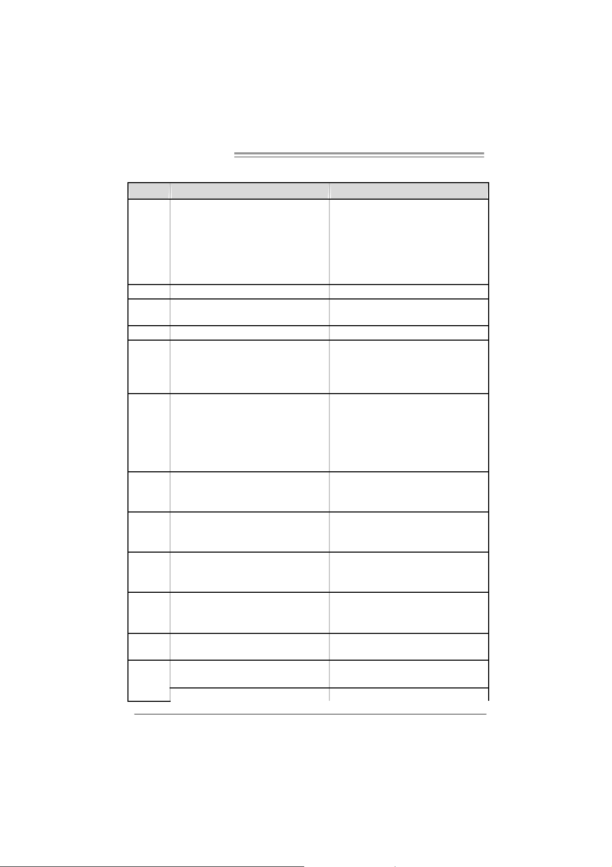
1.3 MOTHERBOARD FEATURES
865 G Micr o 775 865 GV Micr o 775
LGA 775
Intel Pentium 4 / Pentium D / Celeron D
processor up to 3.4 GHz
Supports Hyper-Threading
Execute Disable Bit
Enhanced Intel SpeedS tep
Extended Mem ory 64 Technology
Int el 865GV
Intel ICH5
ITE I T8712F
H/W Monitor
Fan Speed Controller
ITE's "Smart Guardian" funct ion
DIMM Slots x 2
Eac h DIMM supports 128/256/512MB & 1GB
DDR
Max Memory Capicity 2GB
Dual Channel Mode DDR memory module
Supports DDR 266 / 333 / 400
Integrated IDE Controller
Ultra DM A 33~100 Bus Mast er Mode
supports PIO Mode 0~4,
Integrated Serial ATA Controller
Data transfer rates up to 1.5 Gb/s.
SATA V ersion 1.0 specificat ion compliant.
Realtek RTL 8100C
10 / 100 Mb/s auto negoti ation
Half / Full duplex capability
ALC655 / 658
6 channels audio out
AC’97 Vers ion 2.3
CPU
FSB
Chipset
Graphics
Super I/O
Main
Memory
IDE
SA TA
10/100 LAN
Sound
Codec
Slots
On Board
Connector
2
LGA 775
Intel Pentium 4 / Pentium D / Celeron D
processor up to 3.4 GHz
Supports Hyper-Threading
Execute Disable Bit
Enhanced Intel SpeedS tep
Extended Mem ory 64 Technology
533 / 800 MHz 533 / 800 MHz
Int el 865G
Intel ICH5
Intel Extreme Graphics 2 Intel Extreme Graphics 2
ITE I T8712F
H/W Monitor
Fan Speed Controller
ITE's "Smart Guardian" funct ion
DIMM Slots x 2
Eac h DIMM supports 128/256/512MB & 1GB
DDR
Max Memory Capicity 2GB
Dual Channel Mode DDR memory module
Supports DDR 266 / 333 / 400
Integrated IDE Controller
Ultra DM A 33~100 Bus Mast er Mode
supports PIO Mode 0~4,
Integrated Serial ATA Controller
Data transfer rates up to 1.5 Gb/s.
SATA V ersion 1.0 specificat ion compliant.
Realtek RTL 8100C
10 / 100 Mb/s auto negoti ation
Half / Full duplex capability
ALC655 / 658
6 channels audio out
AC’97 Vers ion 2.3
AGP 8X graphics slot x1 XGP graphics slot x1
PCI s lot x3 PCI s lot x3
Fl oppy c onnecto r x1 Fl oppy c onnect or x1
IDE C onnect or x2 IDE Connector x2
SA TA Co nnect or x2 SATA Connect or x 2
Page 5

865G Micro 775 & 865GV Micro 775
865 G Micr o 775 865 GV Micr o 775
Front Panel Connector x1 Front Panel Connector x1
Front Audio Connector x1 Front A udio Connector x1
CD- in C onnec tor x1 C D-i n Connector x1
S/PDIF in connector (optional) x1 S/PDIF in connector (optional) x1
S/PDIF out connector x1 S/PDIF out connector x1
CP U Fa n header x1 C PU F an header x1
Sys tem F an header x1 S ystem Fan hea der x1
Chassis open header (optional) x1 Chassis open header (optional) x1
Clear CMOS header x1 Clear CMOS header x1
USB connector x2 US B c onnector x2
Power Connector (20pin) x1 Power Connector (20pin) x1
Power Connector (4pin) x1 Power Connector (4pin) x1
PS/2 Keyboard x1
PS/2 Mouse x1
S e ri a l P ort x 1
Printer Port x1
VGA port x1
LAN port x1
USB Port x4
Audio Jack x3
Wi ndows 2000 / XP
Biostar Reserves the right to add or remove
support for any OS with or without notice.
Back Panel
I/O
Board Size
OS S upport
PS/2 Keyboard x1
PS/2 Mouse x1
S e ri a l P ort x 1
Printer Port x1
VGA port x1
LAN port x1
USB Port x4
Audio Jack x3
215 (W) x 235 (L) mm 215 (W) x 235 (L) mm
Wi ndows 2000 / XP
Biostar Reserves the right to add or remove
support for any OS with or without notice.
1.4 REAR PANEL CONNECTORS
PS/2
Mouse
PS/ 2
Keyboard
COM 1 USBX2USBX2
Printer Port
(op ti ona l)
VGA1
LAN
Line In/
Surround
Line Out
Mic In 1/
Bass/ Center
3
Page 6
Motherboard Manual
A
_
(op
)
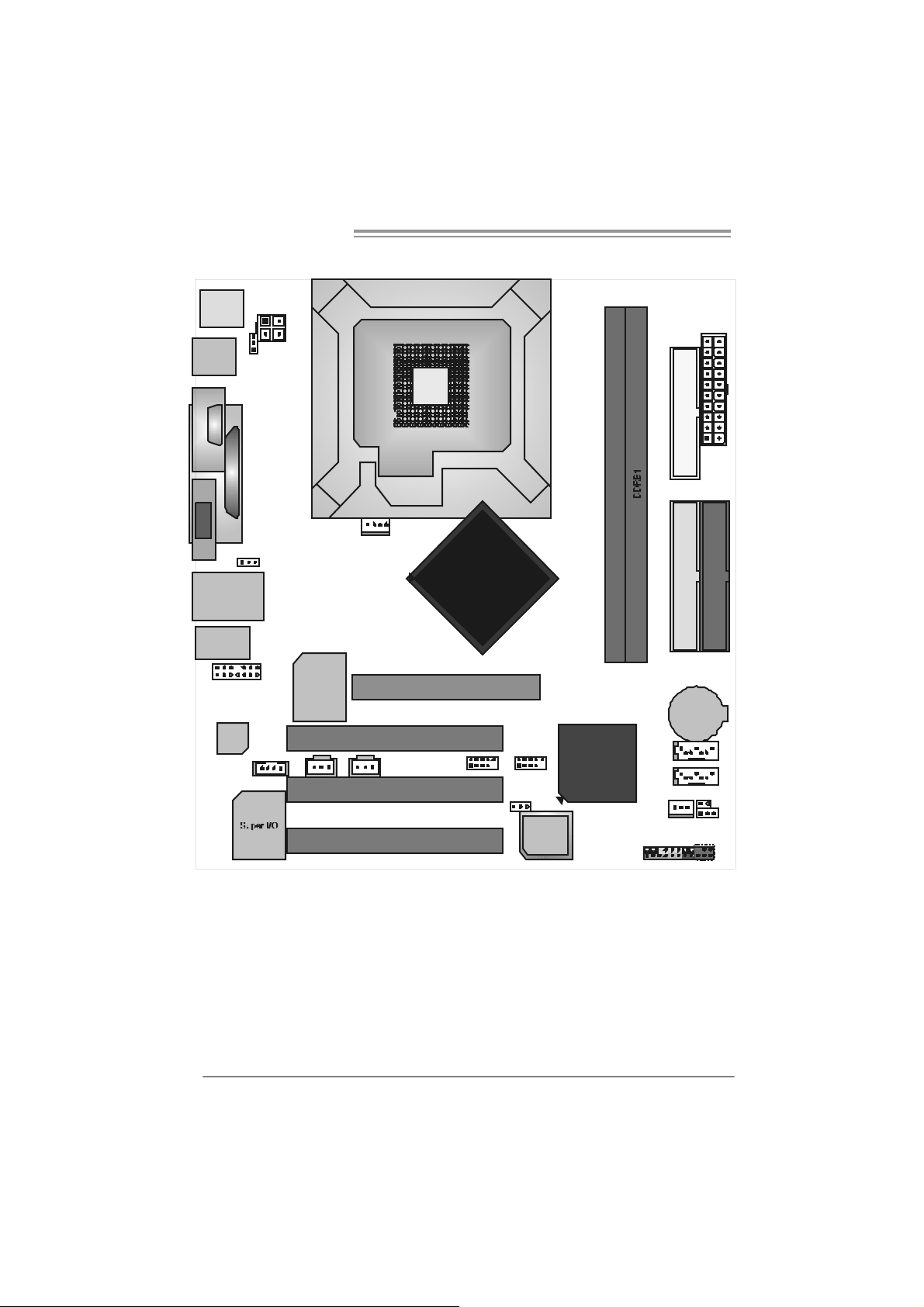
1.5 MOTHERBOARD LAYOUT OF 865G MICRO 775
JKBMS1
JATX PW R2
LGA775
JUSB1
JKB_ US BV1
(optional)
CPU1
C
JCOM1
O
M
1
JPRNT1
JATXPWR1
FD D1
JVGA1
JUSBLAN1
JA UD IO 1
JAUDIO2
Codec
JUSB V2
(optional)
(Optional)
JSPDIF_ IN1
JCDIN1
Note: represents the 1■
LAN
JCFAN1
PCI1
JS PDIF _OU T1
PC I2
PC I3
GP1
st
pin.
Intel
865G
JUSB3JUSB2
JUSBV3
tional
4
BIO S
ICH5
DDRA 1
IDE2
IDE1
BAT1
SATA2
SATA1
JCI1
JSFAN1
JCMOS1
JPA NEL1
IR (op t io nal)
4
Page 7

865G Micro 775 & 865GV Micro 775
1.6 MOTHERBOARD LAYOUT OF 865GV MICRO 775
JKBMS1
JATX PW R2
JATXPWR1
FD D1
JUSB1
COM1
JCOM1
LGA775
CPU1
JPRNT1
JVGA1
JUSBLAN1
JA UD IO 1
JAUDIO2
Code c
(Optional)
JSPDIF_ IN1
JCDIN1
Note: represents the 1■
LAN
JCFAN1
PCI1
JS PDIF _OU T1
PC I2
PC I3
XGP1
st
pin.
Intel
865GV
DDRA 1
IDE2
IDE1
BAT1
JUSB3JUSB2
ICH5
SATA2
SATA1
JSFAN1
JCI1
JCMOS1
BIO S
JPA NEL1
IR (op t io nal)
5
Page 8
Motherboard Manual
CHAPTER 2: HARDW ARE INSTALLATION
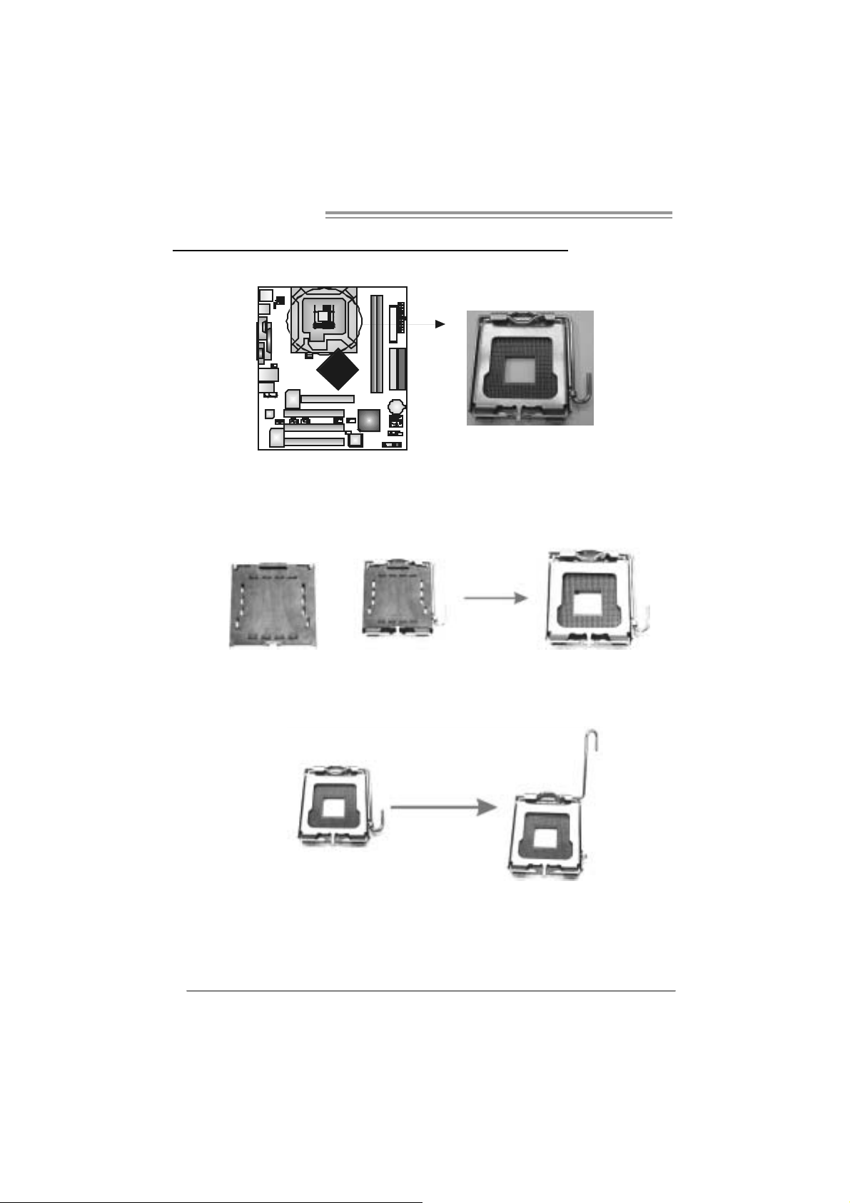
2.1 INSTALLING CENTRAL PROCESSING UNI T (CPU)
Special Notice:
Remo v e Pin Cap before installa tion, and m ake goo d preservation
for future use. When the CPU is remo ved, cov er the Pin Cap on the
empty so cket to ensure pin legs won’ t be da mag ed.
Pin Cap
Step 1: Pull the socket locking lever out from the socket and then raise
the lever up to a 90-degree angle.
6
Page 9
865G Micro 775 & 865GV Micro 775
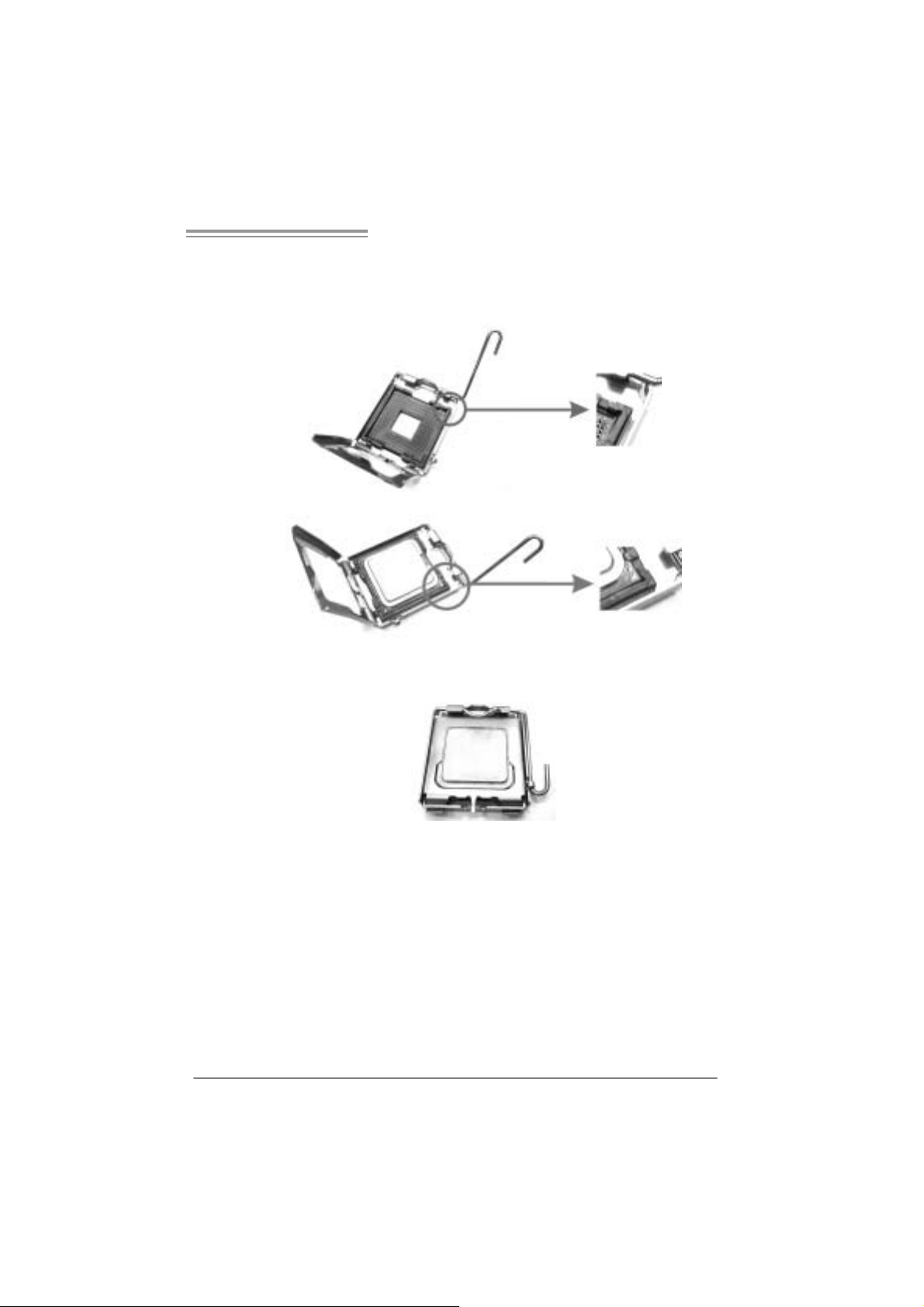
Step 2: Look for the triangular cut edge on socket, and the golden dot on
CPU should point forwards this tri angular cut edge. The CPU will
fit onl y in the correct orientation.
Step 2-1:
Step 2-2:
Step 3: Hold the CPU down firml y, and then lower the lever to locked
positi on to complete the installatio n.
Step 4: Put the CPU Fan and heatsink assem bly on the CPU and buckle it
on the retention fram e. Connect the CPU FAN power cable into
the JCFA N1. This comple te s the install a tion .
7
Page 10
Motherboard Manual
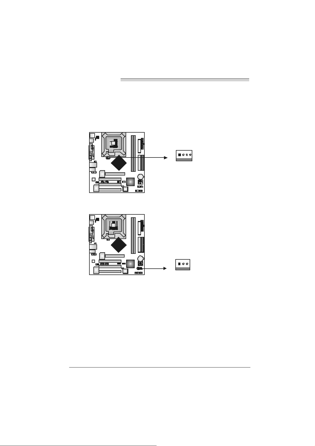
2.2 FAN HEADERS
These fan headers support cooling-fans built i n the com puter. The fan
cable and connector may be different according to the fan manufacturer.
Connect the fan cable to the connector while m atching the black wire to
pin#1.
JCFAN1: CPU Fan Header
14
JCFAN1
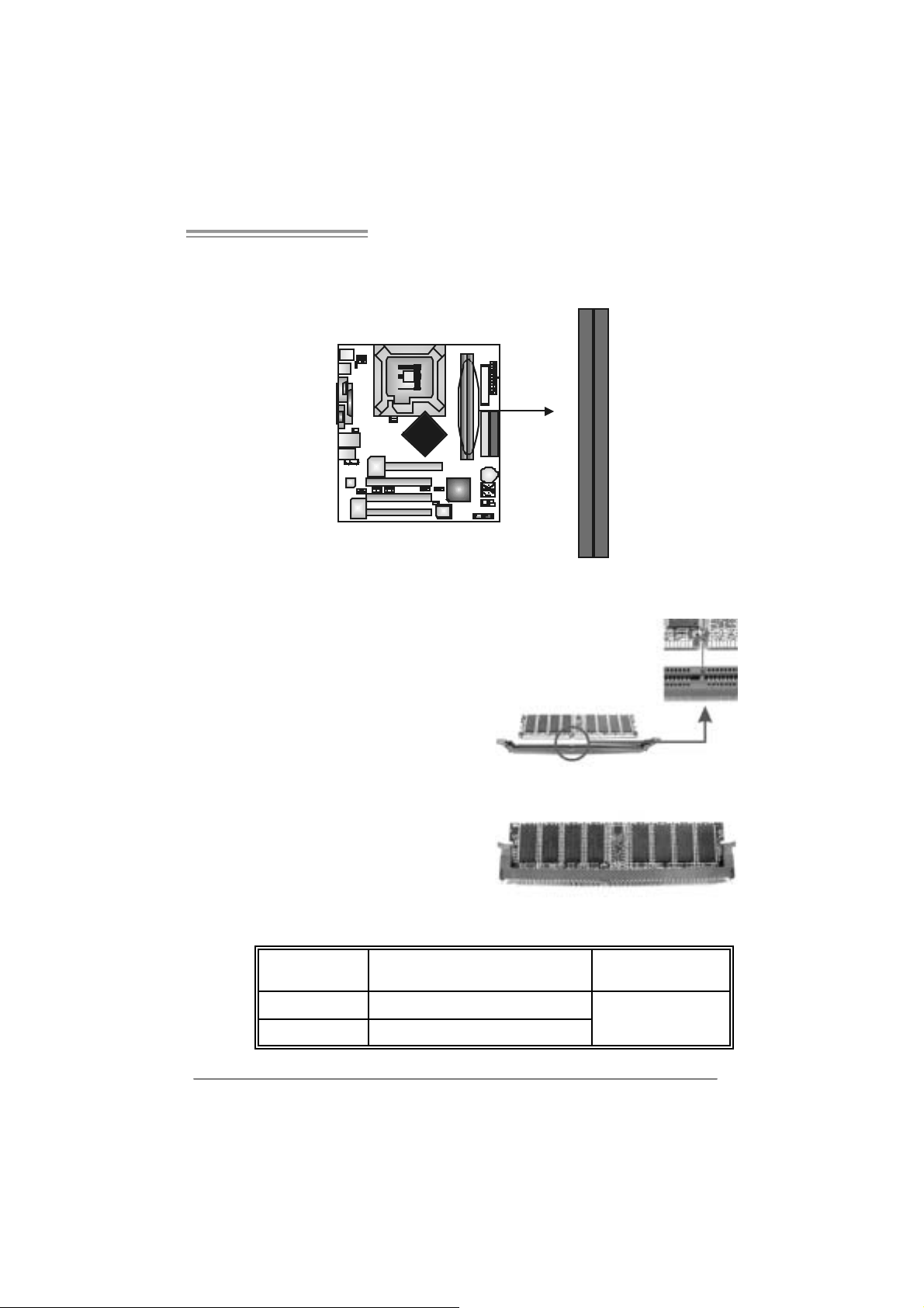
JSF AN1 : Sy stem Fan H eader
13
Pin
Assignment
1 Ground
2 +12V
3
FAN RPM rate
sense
4 Smart Fan
Control
Pin
Assignment
1 Ground
2 +12V
3 FAN RPM rate
sense
JSFAN1
Note:
The JSFAN1 support 3-pin head connector. When connecting with wires onto connectors,
please note that the red wire is the positi ve and should be connected to pin#2, and the
black wire is Ground and should be c onnected to GND.
8
Page 11
865G Micro 775 & 865GV Micro 775
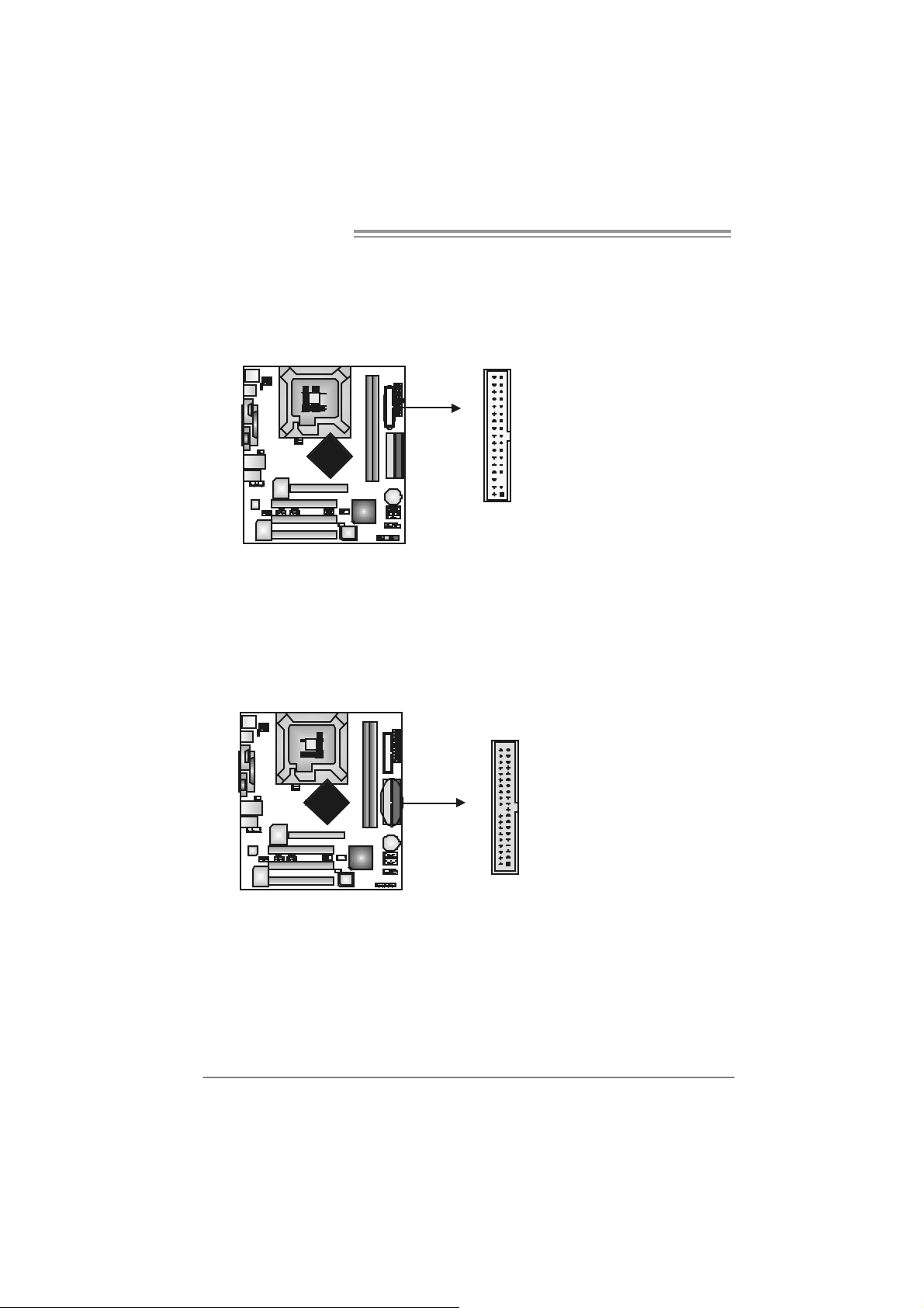
2.3 INSTALLING SYSTEM MEMORY
A. Me mo ry Modu le s
DDRB1
DDRA1
1. Unl ock a DIMM slot by pressi ng the retaining clips outward. Align a
DIMM on the slot such that the notch on the DIMM matches the
break on the Slot.
2. Insert the DIMM vertically and fi rmly into the slot until the retaining
chip snap back in place and the DIM M is properly seated.
B. Memory Capacity
DI MM Socket
Location
DDRA1 256MB/512MB/1GB *1
DDRB1 256MB/512MB/1GB *1
DDR Module Total Memory Size
Max i s 2G B.
9
Page 12
Motherboard Manual
2.4 CONNECTORS AND SLOTS
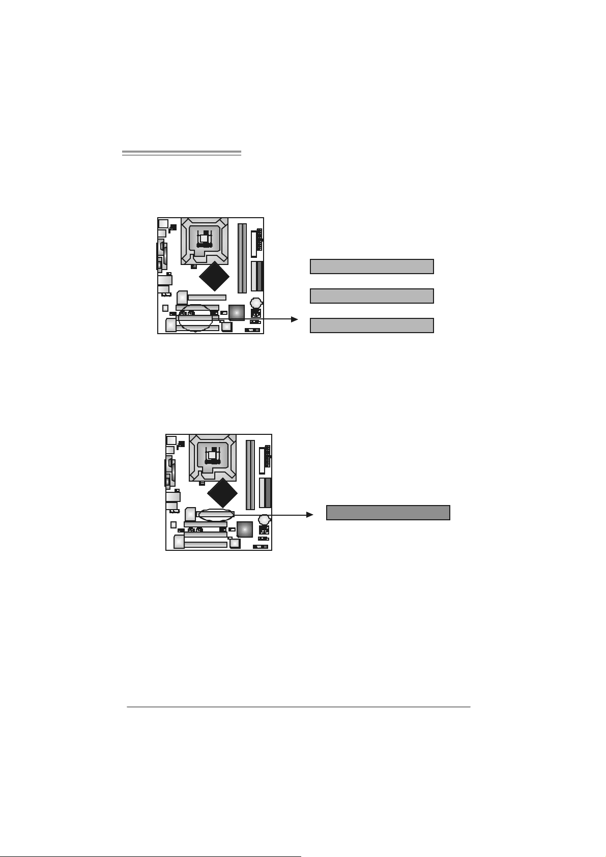
FDD1: Floppy Disk Connector
The motherboard provides a st andard f loppy disk c onnector that supports 360K,
720K, 1. 2M, 1.44M and 2.88M floppy disk types . This c onnector support s the
provided f loppy driv e ribbon cables .
IDE1/IDE2: Ha rd Di sk Connectors
The motherboard has a 32-bit Enhanced PCI IDE Cont roller that prov ides PI O
Mode 0~4, Bus Master, and Ultra DMA 33/ 66/100 f unctionality. I t has t wo H DD
connec t ors I D E1 (prim ary) and IDE2 (secondary).
The IDE connectors can c onnect a m aster and a slav e driv e, so y ou can
connec t up t o f our hard disk drives. The first hard driv e should always be
connec t ed to IDE1.
34 33
12
10
3940
21
IDE2 IDE1
Page 13
865G Micro 775 & 865GV Micro 775
A
PCI1~PCI3: Periphe ral Component In terconnect Slots
This mot herboard is equipped with 3 st andard PCI slot s. PC I stands for
Peripheral Com ponent I nt erc onnect, and it is a bus st andard for ex pansion
cards . This PCI s lot is designat ed as 32 bits.
PCI1
PCI2
PCI3
AGP1: Accele rated Graphics Port Slot ( 865G Micro 775 only )
Your m onit or will attach direct ly to that v ideo card. This motherboard supports
video c ards f or PC I slots , but it is also equipped with an Accelerated Graphics
Port (AGP). An AGP card will tak e adv antage of AGP technology f or im prov ed
video efficiency and perf ormance, es pec ially with 3D graphics.
GP
11
Page 14
Motherboard Manual
XGP1: Xtreme Graphics Port Slot ( 865GV Micro 775 only )
This XGP (Ex t rem e Graphics Port) s lot is a s pecial des ign that only s upports
com patible AGP VGA cards.
To inst all t he sy stem with an add-on AGP VGA card, please make sure t o install
the driver of add-on AGP VGA c ard bef ore onboard VGA driver inst allat ion. If t he
onboard VGA driv er has already been installed bef ore y ou install the add-on
AGP VGA c ard, the sys t em will aut om atically s et the onboard VGA as t he
primary graphics adapter.
For t he onboard VGA driver can’t be remov ed com plet ely, and to s olv e this
problem, please f ollow the steps below,
1. D is able onboard VGA utility under t he operating sys t em, and reboot PC. After
PC restarts, t he sys t em will autom atically s et the AGP VGA card as the
graphics adapter.
2. Or, re-inst all your operat ing sy s t em to ensure t he AGP VGA card function can
be used.
Note:
Pl e a se g o t o “ht tp://www.b i o st ar.co m.tw” fo r m o r e de ta i l e d inf o r mati o n about
XGP compatible AGP cards.
12
XGP
Page 15
865G Micro 775 & 865GV Micro 775
_
)
CHAPTER 3: HE ADERS & J UMPERS SETUP
3.1 HOW TO SET UP JUMPERS
The illustration shows how to set up jumpers. When the jumper cap is
placed on pins, the jumper is “close”, if not, that means the j umper is
“open”.
Pin opened Pin closed Pin1-2 closed
3.2 DETAIL SETT INGS
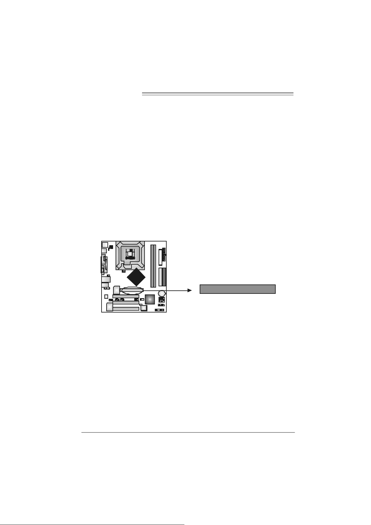
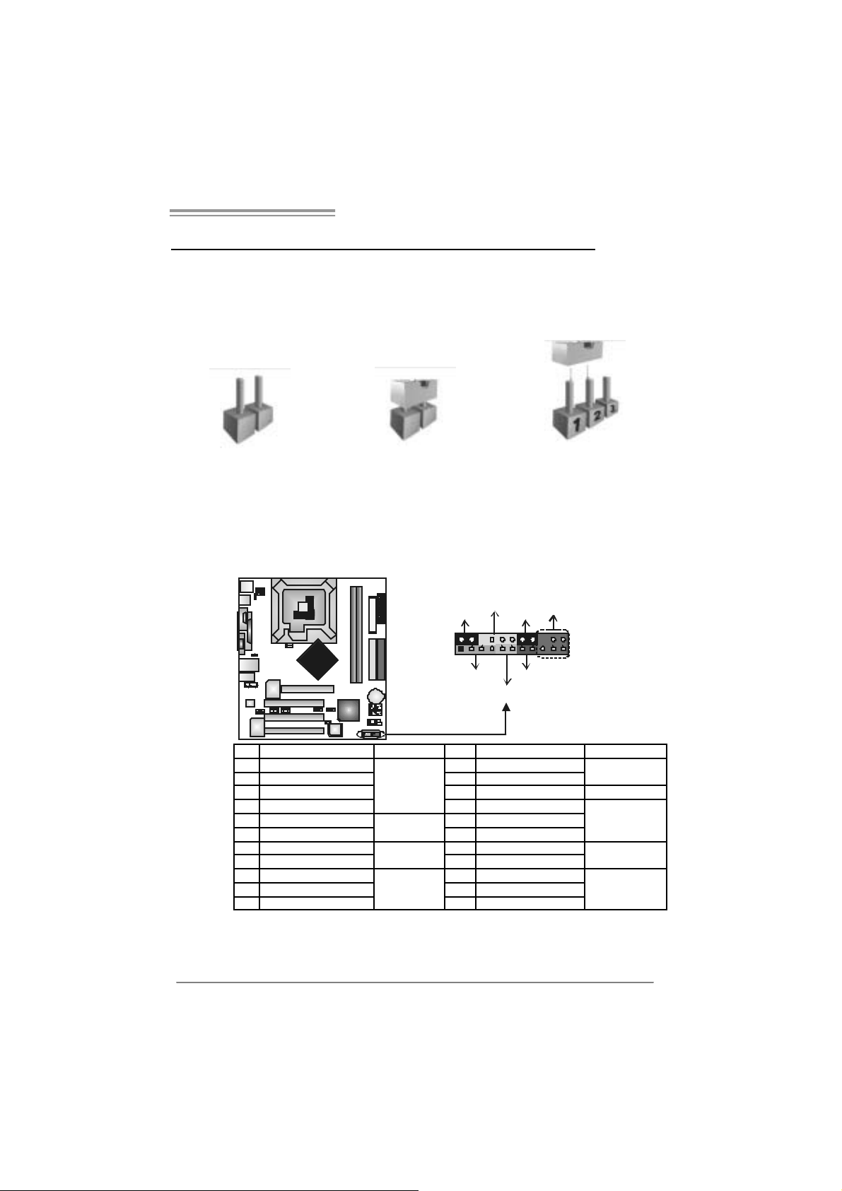
JPANEL1: Front Panel Header
This 22-pin connector includes Power-on, Reset, HDD LED , Power LED, Sleep
butt on, speaker and I rD A Connec t ion. I t allows user t o connect t he PC case’s
front panel switch fun ctions.
PWR
LED
SLP
++
12
111
+
SPK
HLED
On/Off
-
RST
IR (optional
22
Pin Assignment Function Pin Assignment Function
1 +5V 2 Sleep control
3 N/A 4 Ground
5 N/A 6 N/A N/A
7 Speaker
9 HDD LED (+) 1 0 Power LED (+)
11 HDD LED (-)
13 Ground 14 Power button
15 Reset control
17 N/A 18 Key
19 +5V 20 Ground
21 IRTX
Speaker
Connector
Hard drive
LED
Reset button
IrDA
Connector
8 Power LED (+)
12 Pow er LED (-)
16 Ground
22 IRRX
Sleep button
Powe r LED
Power-on button
IrDA Connector
13
Page 16
Motherboard Manual
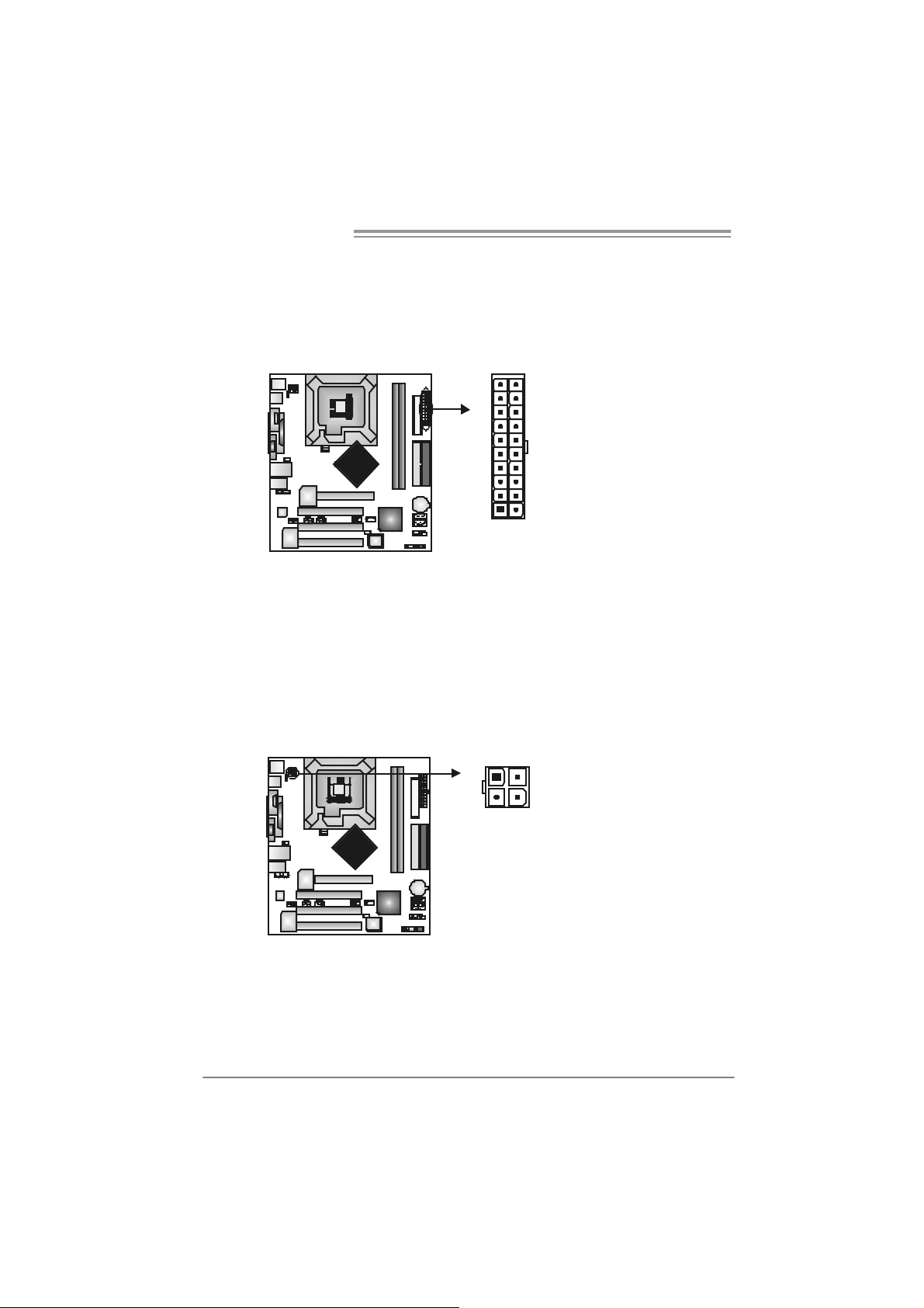
JATXPW R1: ATX Power S ou rce Conne ctor
This connector allows user t o connect 20-pin power connector on the ATX
power supply .
Pin Assignment
1 +3.3V
2 +3.3V
3 Ground
10
20
1
11
4 +5V
5 Ground
6 +5V
7 Ground
8 PW_OK
9 Standby Voltage
+5V
10 +12V
11 +3 .3V
12 -12V
13 Ground
14 PS_ON
15 Ground
16 Ground
17 Ground
18 -5V
19 +5V
20 +5V
JATXPW R2: ATX Power S ou rce Conne ctor
By c onnecting this c onnector, it will prov ide +12V t o C PU power circ uit.
14
13
24
Pin
1 +12V
2 +12V
3 Ground
4 Ground
Assignment
Page 17
865G Micro 775 & 865GV Micro 775
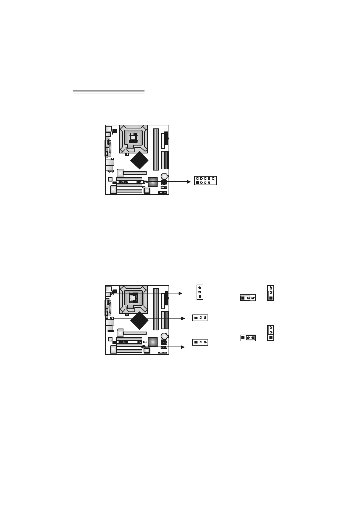
JUSB2/JUSB3: Heade rs for USB 2.0 Ports at Fron t Panel
This header allows us er t o connect addit ional USB c able on t he PC f ront panel,
and also can be c onnec t ed wit h internal U SB dev ic es, like U SB card reader.
Assignment
Pin
1 +5V (fused)
2 +5V (fused)
3 USB4 USB5 USB+
6 USB+
7 Ground
2
1
10
9
JUSB2 JUSB3
JK B_USBV1/JU SBV 2/ JUSB3 _4 : P ower S o urce H ead er s for US B
Ports
Pin 1- 2 Close:
JKB_U SBV1: +5V for USB port s at JU SBLAN 1.
JU SBV2/JU SB3_4: +5V for USB ports at front panel (JU SB2/JUSB3).
Pin 2- 3 Close:
JKB_U SBV1: USB ports at JUSBLAN1 are powered by +5V s t andby
voltage.
JU SBV2/JU SB3_4: U SB ports at f ront panel (JU SB2/JU SB3) are powered
by +5V standb y voltage.
8 Ground
9 Key
10 NC
3
1
JKB_USBV1
13
31
Pin 1-2 close
JUSBV2
1
13
JUSBV3_4
3
Pin 2-3 close
Note:
In order to support this f unc tion “Power-On s y stem via U SB device,” “JKB_USBV1/
JUSBV2/JUSB3_4” jumper cap should be pl aced on Pin 2-3 individuall y.
3
1
3
1
15
Page 18

Motherboard Manual
JAUDIO2: Front P anel Audio Header
This header allows us er to connect the front audio out put cable wit h the PC front
panel. It will dis able t he output on back panel audio connectors.
JCDIN1: CD-R OM Aud io-in Connector
This connector allows us er to c onnect the audio s ourc e from the variaty dev ices,
like CD-R OM, D VD -ROM, PC I sound card, PCI TV t urner card etc..
Pin Assignment
1 Mic in/center
2 Ground
3 Mic power/Bass
4 Audio power
5 Right li ne out/
Speaker out Right
6 Right li ne out/
Speaker out Right
7 Reserved
8 Key
9 Left line out/
2
1
14
13
Pin
14
Speaker out Left
10 Left line out/
Speaker out Left
11 Right line in/
Rear speaker
Right
12 Right line in/
Rear speaker
Right
13 Left line in/
Rear speaker Left
14 Left line in/
Rear speaker Left
Assignment
1 Left Channel
Input
2 Ground
3 Ground
4 Right Channel
Input
16
Page 19
865G Micro 775 & 865GV Micro 775
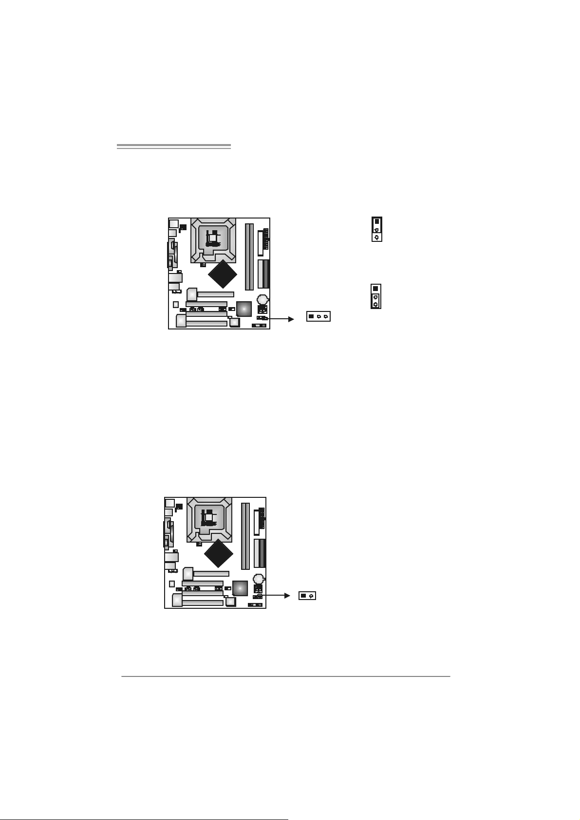
JCMOS 1: C lear CMO S H ea der
By plac ing the jum per on pin2-3, it allows user t o restore the BI OS safe set t ing
and the CMOS data, please c arefully f ollow t he proc edures to av oid damaging
the m otherboard.
1
3
Pin 1-2 Close:
Normal Operation (default).
1
13
3
Pin 2-3 Close:
Clear CMOS data.
※ Clear CMOS Procedures:
1. R em ov e AC power line.
2. Set the jumper to “Pin 2-3 close”.
3. Wait fo r five se co n ds.
4. Set the jumper to “Pin 1-2 close”.
5. Power on the AC.
6. R es et your desired pas s word or c lear the C MOS data.
JCI1: Chassis O pen Head er (optional)
This connector allows sy stem to monitor PC c as e open stat us. If the s ignal has
been triggered, it will rec ord t o the C MOS and s how the message on next
boot-up.
Pin
Assignment
1 Case open signal
2 Ground
12
17
Page 20
Motherboard Manual
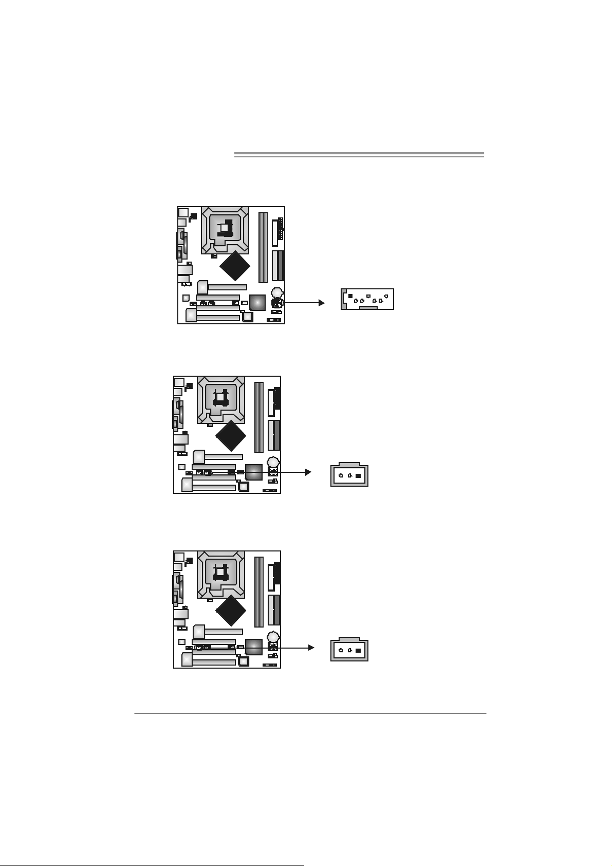
JSATA1~ JS ATA2 : Serial ATA Connectors
The motherboard has a PCI t o SATA C ont roller wit h 2 channels SATA interface,
it satisfies the SATA 1.0 spec and with transfer rate of 1.5GB/s.
JSPDIF_O UT1 : D igital Audio- out Conne ctor
This connector allows user t o connect the PCI bracket SPD IF out put header.
147
Pin
1 +5V
2 SPDIF_OUT
3 Ground
SATA2
SATA1
Assignment
Pin
Assignment
1 Ground
2 TX+
3 TX4 Ground
5 RX6 RX+
7 Ground
JSPDIF_IN1 (optional): Digital Audio-in Connector
This connector allows user t o connect the PCI bracket SPD IF input header.
18
13
Pin
1 +5V
2 SPDIF_IN
3 Ground
13
Assignment
Page 21
865G Micro 775 & 865GV Micro 775
CHAPTER 5: USEFUL HELP
5.1 D
RIVER INSTALLATION NOTE
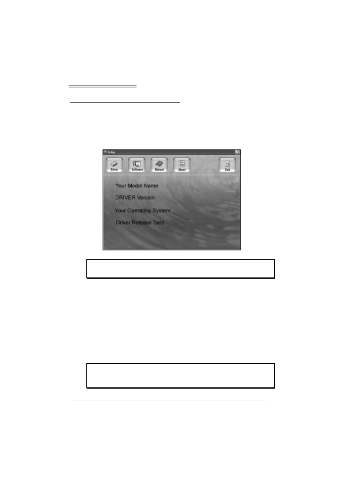
After you installed your operating system, please insert the Fully Setup
Driver CD into your optical drive and install the driver for better system
performance.
You wil l see the following wi ndow after you insert the CD
The setup guid e will aut o d et ect your motherboard and operating system.
Note:
If this window didn’t show up after you ins ert the Driver CD, please use file brow ser to
l ocate and e xecute t h e f il e SET U P.E XE under yo ur opti c al dr ive .
A. Driver Installation
To install the driver, pl ease cli ck on the Dri ver icon. The setup guide will
list the compatible driver for your motherboard and operating system.
Click on each device driver to launch the installation program .
B. Software Installation
To install the software, please cli ck on the Software i con. The setup guide
will list the software avail able for your system, click on each software title
to la unch th e ins tal lat io n pr ogr a m.
C. Manu al
Aside from the paperback manual, we also provi de manual in the Driver
CD. Cl i ck on the Manual icon to browse for availabl e manual.
Note:
You w ill need Acrobat Reader to open t he m an ual file . Please dow nload the latest version
of Acrobat Reader so ftware from
http://www.adobe.com/products/acrobat/readst ep2.html
19
Page 22
Motherboard Manual
5.2 AWARD BIOS BEEP CODE
Beep Sound Meanin g
One long beep f ollowed by t wo s hort
beeps
High-low siren sound CPU overheated
One Short beep when system boot-up No error found during POST
Long beeps every ot her second No DRAM detected or inst all
Video card not f ound or v ideo card
mem ory bad
Sys t em will shut down automat ically
5.3 EXT RA INFORMATION
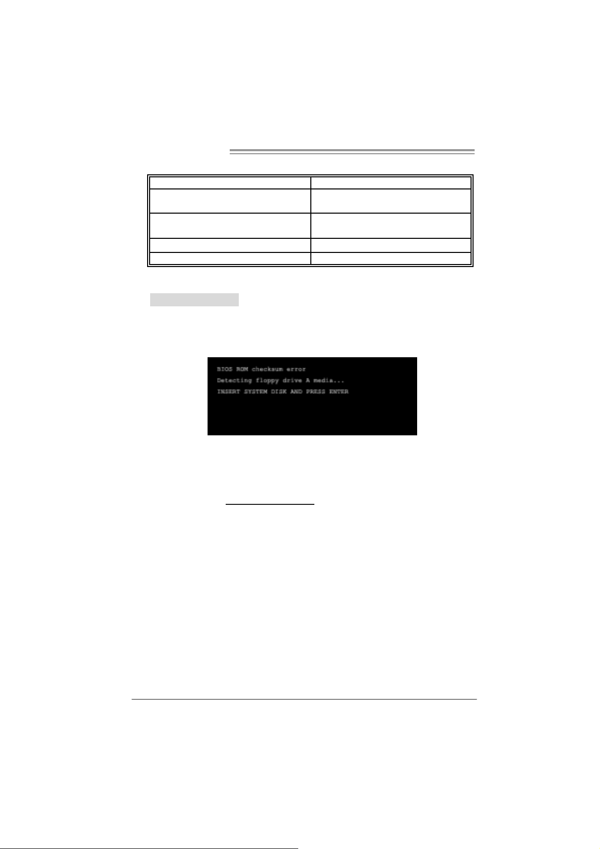
A. BIOS Update
After you fail to update BIOS or BIOS is in vaded by viru s, the
Boot-Block function will help to restore BIOS. If the following message
is shown after boot-up the system, it m eans the BIOS contents are
corrupted.
In this Case, please follow the procedure below to restore the BIOS:
1. Mak e a bootable fl op py dis k.
2. Download the Fl ash Utili ty “AWDFLASH.exe” from the Biostar
website: www.biostar.com.tw
3. Confirm motherboard model and download the respectively BIOS
fr om Bi os t ar w ebsit e.
4. Copy “AWDFLASH.exe” and respectivel y BIOS into fl oppy disk.
5. Insert the bootable disk into floppy drive and press Enter.
6. Sy stem will boot -up to DOS prompt .
7. Type “Awd flash xxxx.bf/ sn/py/ r” in DOS prompt.
(xxxx means BIOS name.)
8. Sy stem will update BIOS a utoma tically and restart.
9. The BIO S h as been recovered an d will work properly.
20
Page 23

865G Micro 775 & 865GV Micro 775
B. CPU Overheated
If the system shutdown automatically after power on system for
seconds, that means the CPU protection function has been activated.
When the CPU is over heated, the motherboard will shutdown
automatically to avoid a damage of the CPU, and the system may not
power on again.
In this case, please double check:
1. The CPU cooler surface i s placed evenly with the CPU surface.
2. CPU fan is ro tated normally.
3. CPU fan speed is fulfil ling with the CPU speed.
After confirmed, please follow ste p s below to relief th e CPU
0protection function.
1. Remove the power cord from power suppl y for seconds.
2. Wait for sec onds.
3. Plug in the power cord and boot up the system.
Or you can:
1. Clear the CMOS data.
(See “Close CMOS Header: JCMOS1” section)
2. Wait for sec onds.
3. Power on the system again.
21
Page 24

Motherboard Manual
e
5.4 TROUBLESHOOTING
Probable Solution
1. N o power to t he sy stem at all
Power light don’t illuminat e, fan
inside power s upply does not turn
on.
2. I ndic at or light on k ey board does
not t urn on.
Sys t em inoperat iv e. Key board lights
are on, power indic at or lights are lit,
and hard drive is s pinning.
Sys t em does not boot f rom hard dis k
drive, can be boot ed f rom opt ic al drive.
Sys t em only boot s f rom optical drive.
Hard disk can be read and applic ations
can be used but boot ing from hard disk
is imposs ible.
Screen m essage say s “Inv alid
Conf igurat ion” or “CMOS Failure. ”
Cannot boot sys t em after inst alling
sec ond hard drive.
1. Make s ure power cable is
sec urely plugged in.
2. Replace cable.
3. Contact techni cal support.
Us ing even pres s ure on both ends of
the DIMM, press down firm ly until the
module s naps int o plac e.
1. C hec k cable running from disk to
disk controller board. Make s ure
both ends are s ec urely plugged
i n; c h ec k the driv e t ype in the
standard CMOS se tup.
2. Bac k ing up t he hard drive is
ext rem ely im port ant . All hard
disk s are c apable of breaking
down at any t im e.
1. Bac k up dat a and applicat ions
files.
2. R ef ormat the hard drive.
Re-ins t all applicat ions and data
using backup disks.
Rev iew sys t em ’s equipment. Mak e sur
correc t information is in setup.
1. Set m as t er/slave jum pers
correctly.
2. R un SETUP program and selec t
correc t drive ty pes. Call t he driv e
manufac turers for co mpatibilit y
with other drives.
22
Page 25

865G Micro 775 & 865GV Micro 775
CHAPTER 6: WARPSPEEDER™
6.1 INTRODUCTION
[WarpSpeeder™], a new powerful control utili ty, features three
user-friendly functions including Overclock Manager, Overvoltage
Manager, and Hardware Moni tor.
Wi th the Overcl ock Manager, users can easil y adjust the frequency they
prefer or they can get the best CPU performance with just one click. The
Overvoltage Manager, on the other hand, helps to power up CPU core
vol tage and Me mor y v ol ta ge. Th e co o l H ar dw are Moni tor s martly in d icates
the temperatures, voltage and CPU fan speed as well as the chi pset
information. Also, in the About panel, you can get detail descri ptions about
BIOS m odel and chipsets. In addi tion, the frequency status of CPU,
mem ory, AGP and PCI along with the CPU speed are synchronicall y
s how n on our ma i n p anel.
Moreover, to protect users' computer systems if the setting i s not
appropriate when testing and resul ts in system fail or hang,
[WarpSpeeder™] technology assures the system stability by automatically
rebooting the computer and then restart to a speed that is ei ther the
ori ginal system speed or a suitable one.
6.2 SYS TEM REQUIREMENT
OS Support: Windows 98 SE, Windows Me, Wi ndows 2000, Windows XP
DirectX: DirectX 8.1 or above. (The Windows XP operati ng system
includes DirectX 8.1. If you use Windows XP, you do not need to instal l
Dir ec tX 8.1.)
23
Page 26
Motherboard Manual
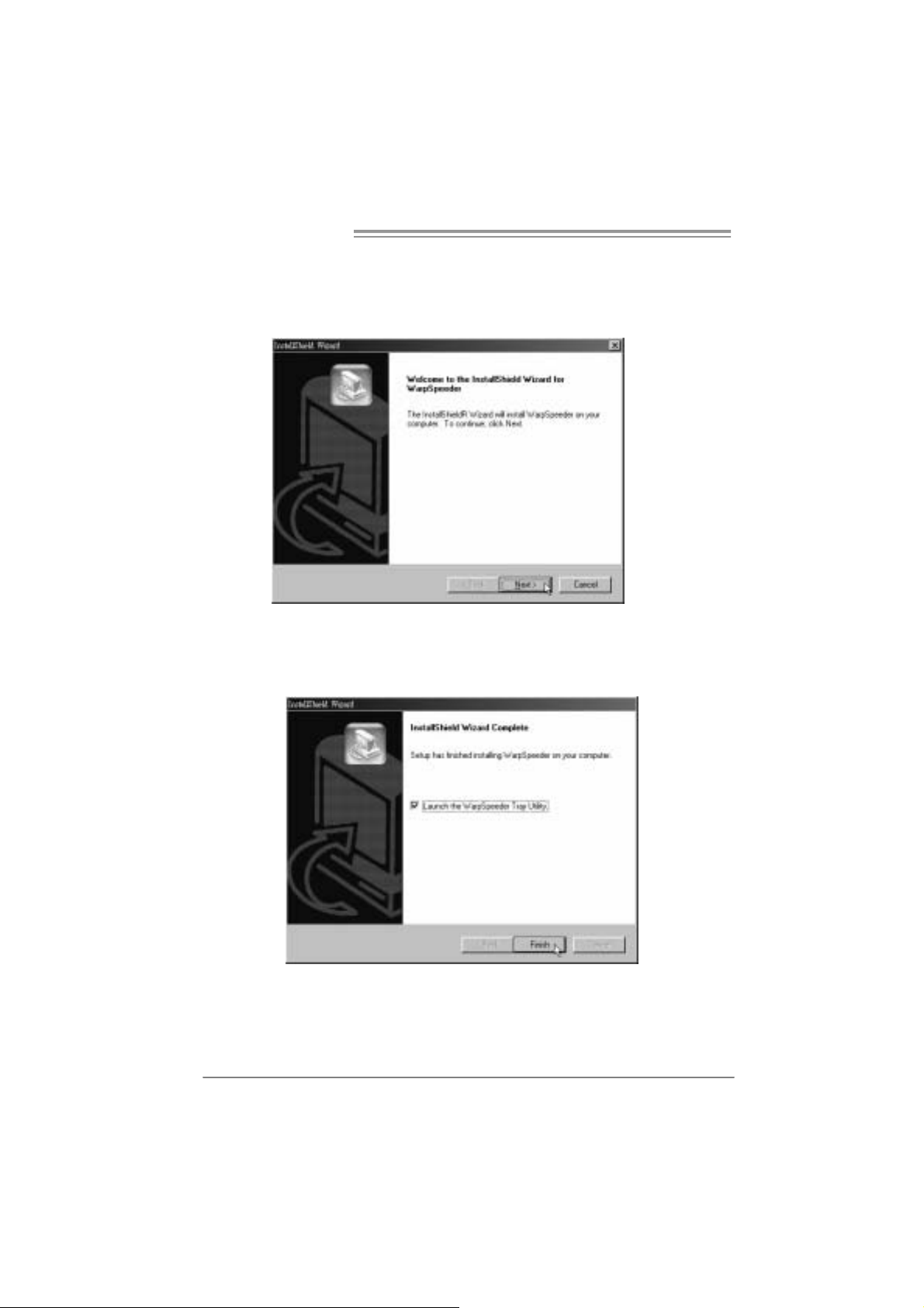
6.3 INSTALLATION
1. Execute the setup execution file, and then the following dial og will pop
up. Please click “Next” button and follow the default procedure to
install.
2. When you see the following dialog in setup procedure, it m eans setup
is completed. If the “Launch the WarpSpeeder Tray Uti lity” checkbox
is che c ked, the Tra y Icon utility and [WarpSp eeder™] utility will b e
automatically and imm ediatel y l aunched after you click “Finish”
button.
24
Usage :
The following figures are just only for reference, the screen printed in
this user man ual will chan ge acc ording to your mothe rbo ard on hand.
Page 27

865G Micro 775 & 865GV Micro 775
6.4 WARPSPEEDER™
1. Tray Icon:
Whenever the Tray Icon utili ty is launched, it will display a little tray
icon on the right si de of Windows Taskbar.
This utility is responsible for conveni entl y i nvoking [WarpSpeeder™]
Utility. You can use the mouse by cli cking the left button in order to
invoke [WarpSpeeder™] di rectl y from the littl e tray icon or you can
ri ght-click the little tray icon to pop up a popup menu as followi ng
figure. The “Launch Utility” item in the popup menu has the same
func tio n as mouse left -click on t ray icon an d “Exi t” item will clo se
T ray Icon utility if selected.
25
Page 28

Motherboard Manual
2. Main Panel
If y ou click the tray icon, [WarpSpeeder™] u tility will be invoked .
Please refer to th e following figu re; th e utility’s first window you will
see is Main Panel.
Main Pane l contains features as follows:
a. D i spl ay the CPU Speed, CPU ex ternal clock, Memor y clock, AGP clock,
and PCI cl ock information.
b. Contains About, Vol tage, Overclock, and Hardware Monitor Buttons for
invoking respective panels.
c. With a user- fr ie ndly Status An im atio n, it can represent 3 ov er c l ock
percentage stages:
Man walking→overclock percentage from 100% ~ 110 %
Panther runni ng→overclock percentage from 110% ~ 120%
Ca r racing→overclock percentage from 120% ~ above
26
Page 29

865G Micro 775 & 865GV Micro 775
3. Voltage Panel
Cli c k the Vol ta ge bu tton in Mai n P anel, th e button will be highligh te d
and the Vol tage Panel will slide out t o up as the follo wing figure .
In this panel, you can decide to increase CPU core voltage and
Memory vo ltag e or not. The default se tting is “No”. If you wan t to get
the best performance of overclocking, we recommend you click the
option “Yes”.
27
Page 30

Motherboard Manual
4. Over clock Panel
Cli c k the Overcloc k button in Main Panel, th e button will be
highlighted and the Overclock Panel will slide out to left as the
fol l owi ng f igur e.
Overclock Panel cont ains the these fea tures:
a. “–3MHz button”, “-1M Hz button”, “+1MHz button”, and “+3MHz button”:
provide user the ability to do real-time overcl ock adjustment.
Warning:
Manually overclock is pot entially dangerous, especially when the
overclocking perc ent age is ov er 110 %. W e strongly rec ommend y ou
verif y every speed y ou overclock by c lick the Verify butt on. Or, you c an
just click Aut o ov erclock but t on and let [W arpSpeeder™] aut om at ic ally
gets the best res ult f or you.
b. “Recovery Dialog button”: Pop up the following dialog. Let user select
a restoring way if system need to do a fail-safe reboot.
28
Page 31

865G Micro 775 & 865GV Micro 775
c. “Auto-overclock button”: User can click this button and
[Wa rpS peede r™] will set the best an d stable pe rformance and
frequency automatically. [WarpSpeeder™] utili ty will execute a
series of testin g until syste m f ail. Then system will do fail-safe
reboot by usi ng Watchdog function. After reboot, the
[WarpSpeeder™] utility will restore to the hardware defaul t
setting or load the verified best and stable frequency according
to th e Recovery Dialog’s setting.
d. “Veri fy button”: User can click this button and [WarpSpeeder™]
will proceed a testing for current frequency. If the testing is ok,
then the cu rrent freq uency will be sa ved into system registry. If
the testi ng fail, system wil l do a fail-safe rebooti ng. After reboot,
the [WarpSpeede r™] u tili ty will re store to the hardware def au lt
setting or load the verified best and stable frequency according
to th e Recovery Dialog’s setting.
Note:
Becaus e the t esting program s, invoked in Auto-overclock and Verify,
include D irectDraw, D irect3D and DirectShow t ests, the D irec t X 8.1 or
newer runtime library is required. And pleas e make sure y our display
card’s color depth is High c olor (16 bit) or True c olor( 24/32 bit ) that is
required for Direc t3D rendering.
5. Hardware Monitor Panel
Cli c k the Hardware Monitor but ton in Main Pa nel, the b utton will be
highlighted and the Hardware Monitor panel will sl ide out to left as
the fo l lowing fig ur e.
In this panel, you can get the real -time status information of your
system. The information will be re freshed every 1 second.
29
Page 32

Motherboard Manual
6. About Panel
Click the “about” button in Main Panel , the button will be highlighted
and the About Pa ne l will sl id e out to up as the fo l lowin g f igur e.
In this panel, you can get model name and detail informati on in hints
of all the chipset that are related to overclocking. You can also get
the mainboard’s BIOS model and the Version number of
[WarpSpeeder™] utility.
30
Note:
Because the overcl ock, overvoltage, and hardware monitor features
are controlled by several separate chipset, [WarpSpeeder™] divide
these features to separate panel s. If one chipset is not on board, the
corr elative button in Main panel will be disabled, but will not interfe r e
other panels’ functi ons. This property can make [WarpSpeeder™]
utility more robust.
Page 33

865G Micro 775 & 865GV Micro 775
APPENDENCIES: SPEC IN OTHER L ANGUAGE
G
ERMAN
865 G Micr o 775 865 GV Micr o 775
LGA 775
Intel Pentium 4 / Pentium D / Celeron D
Prozessoren mit bis zu 3,4 GHz
CPU
FSB 400/ 533 / 800 M Hz 400/ 533 / 800 M Hz
Chipsatz
Grafi k
Super E/A
Arbeitsspeic h
er
IDE
SA TA
LAN
Audio-Codec
Unterstützt Hyper-Threading
Execute Disable Bit
Enhanced Intel SpeedS tep®
Extended Mem ory 64 Technology
Int el 865 G
Intel ICH5
Intel Extreme Graphics 2 Intel Extreme Graphics 2
ITE 8712F
Hardware-Überwachung
Lüfterdrehzahl-Controller
"Smart Guardian"-Funktion von I TE
DDR DIMM -Steckplätze x 2
Jeder DI MM unterst ützt 128/256/512MB & 1GB
DDR
M ax. 2GB Arbeitss peic her
Dual-Kanal DDR Speichermodul
Unt erstüt zt DDR 266 / 333 / 400
Integrierter IDE-Controller
Ultra DM A 33 / 66 / 100 Bus Mas ter -M odus
Unterstützt PIO-Modus 0~4
I nt e gr i ert e r S e ri al ATA - Con tr o ll e r
Datentransferrate bis zu 1.5Gb/s
Konform mit der SATA-Spezifikation Version 1.0
Realtek 8100C
10 / 100 Mb/s Auto-Negotiation
Halb-/ Vollduplex-Funktion
ALC 655 / ALC 658
6-Kanal-A udioausgabe
AC’97 Vers ion 2.3
LGA 775
Intel Pentium 4 / Pentium D / Celeron D
Prozessoren mit bis zu 3,4 GHz
Unterstützt Hyper-Threading
Execute Disable Bit
Enhanced Intel SpeedS tep®
Extended Mem ory 64 Technology
Int el 865 GV
Intel ICH5
ITE 8712F
Hardware-Überwachung
Lüfterdrehzahl-Controller
"Smart Guardian"-Funktion von I TE
DDR DIMM -Steckplätze x 2
Jeder DI MM unterst ützt 128/256/512MB & 1GB
DDR
M ax. 2GB Arbeitss peic her
Dual-Kanal DDR Speichermodul
Unt erstüt zt DDR 266 / 333 / 400
Integrierter IDE-Controller
Ultra DM A 33 / 66 / 100 Bus Mas ter -M odus
Unterstützt PIO-Modus 0~4
I nt e gr i ert e r S e ri al ATA - Con tr o ll e r
Datentransferrate bis zu 1.5Gb/s
Konform mit der SATA-Spezifikation Version 1.0
Realtek 8100C
10 / 100 Mb/s Auto-Negotiation
Halb-/ Vollduplex-Funktion
ALC 655 / ALC 658
6-Kanal-A udioausgabe
AC’97 Vers ion 2.3
31
Page 34

Motherboard Manual
865 G Micr o 775 865 GV Micr o 775
Steckplätze
Onboard-Ans
chluss
Rückseiten-E
/A
Platinengröße
.
OS-Unterstüt
zung
AGP 8X-Grafikkartensteckplatz x1 XGP Grafikkartensteckplatz x1
PCI-Steckplatz x3 PCI-Steckplatz x3
Diskettenlaufwe rkansc hluss x 1 Disk ett enlaufw er kansc hl uss x1
IDE-A nschl uss x2 IDE-A nschl uss x2
SATA-Anschluss x2 SATA-Anschluss x2
Fronttafelanschluss x1 Fronttafelanschluss x1
Fr ont-Audi oansc hluss x1 Fr ont-Audi oansc hluss x1
CD-I N- Ansc hluss x1 CD-I N- Ansc hluss x1
S/PDIF-Ausgangsanschluss(optional) x1 S/PDIF-Ausgangsanschluss(optional) x1
S/PDIF Eingangs anschluss x1 S /PDIF Ei nga ngsansc hluss x1
CPU-Lüfter-Sockel x1 CPU-Lüfter-Sockel x1
System-Lüfter-Sockel x1 System-Lüfter-Sockel x1
"Gehäuse offen"-Sockel (optional) x1 "Gehäuse offen"-Sockel (optional) x1
"CMOS lösc hen"-S oc kel x1 "CMOS lösc hen"-S oc kel x1
US B-A nschl uss x2 US B-A nschl uss x2
Stromanschluss (20-polig) x1 Stromanschluss (20-polig) x1
Stromanschluss (4-polig) x1 Stromanschluss (4-polig) x1
PS/2-Tastatur x1
PS/2-Maus x1
Serie ller A nschl uss x1
Drucke ra nsc hl uss x1
VGA-Anschluss x1
LAN-A nsc hl uss x 1
US B-A nschl uss x4
Audioanschluss x3
215 mm (B) X 235 mm (L) 215 m m (B) X 235 m m (L)
Wi ndows 2000 / XP
Biostar behält sich das Recht vor, ohne
Ankündigung die Unterstütz ung für ein
Betriebssystem hinzuz ufügen oder z u
entfernen.
PS/2-Tastatur x1
PS/2-Maus x1
Serie ller A nschl uss x1
Drucke ra nsc hl uss x1
VGA-Anschluss x1
LAN-A nsc hl uss x 1
US B-A nschl uss x4
Audioanschluss x3
Wi ndows 2000 / XP
Biostar behält sich das Recht vor, ohne
Ankündigung die Unterstütz ung für ein
Betriebssystem hinzuz ufügen oder z u
entfernen.
32
Page 35

865G Micro 775 & 865GV Micro 775
FRANCE
865 G Micr o 775 865 GV Micr o 775
LGA 775
Processeurs Intel Pentium 4 / Pentium D /
Celeron D jus qu'à 3,4 GHz
UC
Bus fr ontal 400/ 533 / 800 M Hz 400/ 533 / 800 MHz
Chipset
Graphiques
Super E/S
Mémoire
princi pale
IDE
SA TA
LAN
Codec audio
Fentes Fente graphique AGP 8X x1 Fente graphique XGP x1
Prend en charge les technologies
Hyper-Threading
d'exécuti on de bit de désactivation
Intel SpeedSt ep® optimisée
de mémoire ét endue 64
Int el 865G
Intel ICH5
Intel Extreme Graphics 2 Intel Extreme Graphics 2
ITE 8712F
Monit eur de matériel
Contr ôleur de vitess e de vent ilat eur
Fonction "Gardien intelligent" de l'ITE
Fentes DDR DIMM x 2
Chaque DIMM prend en charge des DDR de
128/256/512 M o et 1Go
Capacité mémoire maximale de 2 Go
Module de mémoire DDR à mode à double voie
Prend en c harge la DDR 266 / 333 / 400
Contrôleur IDE intégré
Mode princ ipale de Bus Ultra DMA 33 / 66 / 100
Prend en c harge le mode PIO 0~4,
Cont r ôl eur Se rial ATA intégré :
Taux de transfert jusqu'à 1.5 Go/s.
Conforme à la spécification SATA Version 1.0
Realtek 8100C
10 / 100 Mb/s négociation automatique
Half / Full duplex capability
ALC 655 / ALC658
Sortie audio à 6 voies
AC’97 Vers ion 2.3
LGA 775
Processeurs Intel Pentium 4 / Pentium D /
Celeron D jus qu'à 3,4 GHz
Prend en charge les technologies
Hyper-Threading
d'exécuti on de bit de désactivation
Intel SpeedSt ep® optimisée
de mémoire ét endue 64
Int el 865GV
Intel ICH5
ITE 8712F
Monit eur de matériel
Contr ôleur de vitess e de vent ilat eur
Fonction "Gardien intelligent" de l'ITE
Fentes DDR DIMM x 2
Chaque DIMM prend en charge des DDR de
128/256/512 M o et 1Go
Capacité mémoire maximale de 2 Go
Module de mémoire DDR à mode à double voie
Prend en c harge la DDR 266 / 333 / 400
Contrôleur IDE intégré
Mode princ ipale de Bus Ultra DMA 33 / 66 / 100
Prend en c harge le mode PIO 0~4,
Cont r ôl eur Se rial ATA intégré :
Taux de transfert jusqu'à 1.5 Go/s.
Conforme à la spécification SATA Version 1.0
Realtek 8100C
10 / 100 Mb/s négociation automatique
Half / Full duplex capability
ALC 655 / ALC658
Sortie audio à 6 voies
AC’97 Vers ion 2.3
33
Page 36

Motherboard Manual
Connecteur
embarqué
E/S du
panneau
arrière
Dim ensions
de la carte
Support SE
Fente PCI x3 Fente PCI x3
Connecteur de disquette x1 Connecteur de disquette x1
Connecteur IDE x2 Connect eur IDE x2
Connect eur SATA x2 C onnecte ur SATA x2
Connecteur du panneau avant x1 C onnecteur du panneau avant x1
Connecteur Audio du panneau avant x1 Connecteur Audio du panneau avant x1
Connecteur d'entrée CD x1 Connecteur d'entrée CD x1
Connecteur d'entrée S/PDIF (en option) x1 Connecteur d'entrée S/PDIF (en option) x1
Connecteur de sortie S/PDIF x1 Connecteur de sortie S/PDIF x1
Embase de ventilateur UC x1 Em bas e de ventilat eur UC x1
Embase de ventilateur système x1 Em bas e de ventilat eur système x1
Embase d' ouverture de c hâssis x1
(optional)
Embase d'effacement CMO S x1 Embase d'effacement CMO S x1
Connecteur USB x2 Connec teur USB x2
Connecteur d'alimentation (20 broches) x1 Connec teur d'alim ent at ion (20 broches) x1
Connecteur d'aliment ation (4 broches) x1 Connecteur d'aliment ation (4 broches) x1
Clavier PS/2 x1
Souris PS/2 x1
Port série x1
Port d'im primante x1
Port VGA x1
Port LAN x1
Port USB x4
Fiche audio x3
215mm (l) X 235 mm (H) 215mm (l) X 235 mm (H)
Wi ndows 2000 / XP
Biostar se réserve le droit d'ajouter ou de
supprimer le support de SE avec ou sans préavis.
865 G Micr o 775 865 GV Micr o 775
Embase d' ouverture de c hâssis x1
(optional)
Clavier PS/2 x1
Souris PS/2 x1
Port série x1
Port d'im primante x1
Port VGA x1
Port LAN x1
Port USB x4
Fiche audio x3
Wi ndows 2000 / XP
Biostar se réserve le droit d'ajouter ou de
supprimer le support de SE avec ou sans préavis.
34
Page 37

865G Micro 775 & 865GV Micro 775
ITALIAN
865 G Micr o 775 865 GV Micr o 775
CPU
FSB
Chipset
Grafica
Super I/O
Memoria
principale
IDE
SATA
LAN
Codec
audio
Alloggi
Connett ori
su scheda
LGA 77 5
Processore Intel Pentium 4 / Pentium D /
Celeron D fino a 3.4 GHz
Suppor to di Hyper -T hreading
Execute Dis able Bit
Enha nc ed Intel Sp eedStep®
Tecnol o gia Extended M emory 64
400 / 5 33 / 800 MHz 400 / 5 33 / 800 MHz
Int el 865GV
Intel I CH5
Intel Extreme Graphics 2 Intel Extreme Graphics 2
ITE 871 2F
Monitoraggio h ardware
Controller velocità ventolina
Funz ione "Sm art G uardi an" di I TE
Al loggi DIMM DDR x 2
Ciascun DIM M s upporta DDR
128 /25 6/ 512MB e 1GB
Capacità massima della memori a 2GB
Modulo di memoria DDR a canale doppio
Support o di DDR 26 6 / 333 / 400
Controller ID E integrato
Modalità Bus Master Ultra DMA 33 / 66 /
100
Suppor to modalità PIO Mode 0-4
Controller Serial ATA integrato
Veloc it à di tras ferimento dei dati fi no a 1.5
Gb/s .
Compatibile specifiche SATA Versione 1.0.
Realtek 8100C
Negoziazione automat ic a 10 / 10 0 Mb /s
Capacità Half / Full Duplex
AL C 655 / AL C 658
Uscita audio 6 canali
AC ’97 V ersione 2. 3
Al loggio grafic a AGP 8X x1 A lloggio grafica X GP x1
Alloggio PCI x3 Alloggio PCI x3
Connett ore flo ppy x1 Connettore flo ppy x1
Connett ore IDE x2 Connettore IDE x2
Connett ore SA TA x2 C onnettore SATA x2
Connett ore pannell o fro ntal e x1 Connettor e pa nnello fro ntale x1
Connettore audio frontale x1 Connettore audio frontale x1
LGA 77 5
Processore Intel Pentium 4 / Pentium D /
Celeron D fino a 3.4 GHz
Suppor to di Hyper -T hreading
Execute Dis able Bit
Enha nc ed Intel Sp eedStep®
Tecnol o gia Extended M emory 64
Int el 865GV
Intel I CH5
ITE 871 2F
Monitoraggio h ardware
Controller velocità ventolina
Funz ione "Sm art G uardi an" di I TE
Al loggi DIMM DDR x 2
Ciascun DIM M s upporta DDR
128 /25 6/ 512MB e 1GB
Capacità massima della memori a 2GB
Modulo di memoria DDR a canale doppio
Support o di DDR 26 6 / 333 / 400
Controller ID E integrato
Modalità Bus Master Ultra DMA 33 / 66 /
100
Suppor to modalità PIO Mode 0-4
Controller Serial ATA integrato
Veloc it à di tras ferimento dei dati fi no a 1.5
Gb/s .
Compatibile specifiche SATA Versione 1.0.
Realtek 8100C
Negoziazione automat ic a 10 / 10 0 Mb /s
Capacità Half / Full Duplex
AL C 655 / AL C 658
Uscita audio 6 canali
AC ’97 V ersione 2. 3
35
Page 38

Motherboard Manual
I/O
pannello
posteriore
Dim ension
i scheda
Sistemi
operativi
supportati
Connettore CD-in x1 Connettore CD-in x1
Connettore input S/PDIF (o ptional) x1 Connettore input S/PDIF (optional) x1
Connettore output SPDIF x1 Connettore output SPDIF x1
Collettore ventolin a CPU x1 Collettore ventolina CPU x1
Collettore ventolina sistema x1 Collettore ventolina sistema x1
Collettore apertur a telaio (optio nal) x1 Collettore apertur a telaio (optional) x1
Collettore cancellazione CMOS x1 Collettore cancellazione CMOS x1
Connett ore USB x2 C onnet tore US B x2
Connettore alimentazione (20 pin) x1 Connettore alimentazione (20 pin) x1
Connettore alimentazione (4 pi n) x1 Connettore alimentazione (4 pi n) x1
Ta s t i er a PS / 2 x 1
Mouse PS/2 x1
Porta seriale x1
Porta s tampante x1
Porta VGA x1
Porta LAN x1
Porta USB x4
Connett ore au dio x3
21 5 mm (l argh ezz a) x 235 mm (al tezz a) 21 5 m m (larghezz a) x 23 5 mm (altezza)
Windows 2000 / XP
Biostar si riserva il diritto di aggiu ngere o
rimuovere il supporto di qualsiasi sistema
operativo se nza pre avviso.
865 G Micr o 775 865 GV Micr o 775
Ta s t i er a PS / 2 x 1
Mouse PS/2 x1
Porta seriale x1
Porta s tampante x1
Porta VGA x1
Porta LAN x1
Porta USB x4
Connett ore au dio x3
Windows 2000 / XP
Biostar si riserva il diritto di aggiu ngere o
rimuovere il supporto di qualsiasi sistema
operativo se nza pre avviso.
36
Page 39

865G Micro 775 & 865GV Micro 775
SPANISH
865 G Micr o 775 865 GV Micr o 775
LGA 775
Procesador Intel Pentium 4 / Pentium D / Celeron
D hasta 3,4 GHz
CPU
FSB 400 / 533 / 800 MHz 400 / 533 / 800 MHz
Conjunto de
chips
Gráficos
Súper E/S
Memoria
princi pal
IDE
SA TA
Red Local
Códecs de
sonido
Ranuras
Admite Hyper-Threading
Bit de deshabilitación de ejecución
Intel SpeedSt ep® Mejorado
Tecnología Extended Memory 64
Int el 865G
Intel ICH5
Intel Extreme Graphics 2 Intel Extreme Graphics 2
ITE 8712F
Monitor hardware
Controlador de velocidad de ventilador
Función "Guardia inteligente" de ITE
Ranuras DIMM DDR x 2
Cada DIMM admite DDR de 128/256/512MB y
1GB
Capacidad máxima de memoria de 2GB
Módul o de m emori a DDR de canal Doble
Admi te DDR de 266 / 333 / 400
Controlador IDE int egrado
Modo bus maestro Ult ra DMA 33 / 66 / 100
Soporte los Modos PIO 0~ 4.
Controlador ATA Serie Int egrado
Tasas de transferencia de hasta 1.5 Gb/s.
Compatible con la versión SATA 1. 0.
Realtek 8100C
Negociac ión de 10 / 100 M b/s
Funciones Half / Full dúplex
ALC 655 /ALC 658
Salida de sonido de 6 canales
AC’97 Vers ión 2.3
Ranura de gráfic os AGP x8 x1 Ranura de gráficos XGP x1
Ranura PCI X3 Ranura PCI X 3
LGA 775
Procesador Intel Pentium 4 / Pentium D / Celeron
D hasta 3,4 GHz
Admite Hyper-Threading
Bit de deshabilitación de ejecución
Intel SpeedSt ep® Mejorado
Tecnología Extended Memory 64
Int el 865GV
Intel ICH5
ITE 8712F
Monitor hardware
Controlador de velocidad de ventilador
Función "Guardia inteligente" de ITE
Ranuras DIMM DDR x 2
Cada DIMM admite DDR de 128/256/512MB y
1GB
Capacidad máxima de memoria de 2GB
Módul o de m emori a DDR de canal Doble
Admi te DDR de 266 / 333 / 400
Controlador IDE int egrado
Modo bus maestro Ult ra DMA 33 / 66 / 100
Soporte los Modos PIO 0~ 4.
Controlador ATA Serie Int egrado
Tasas de transferencia de hasta 1.5 Gb/s.
Compatible con la versión SATA 1. 0.
Realtek 8100C
Negociac ión de 10 / 100 M b/s
Funciones Half / Full dúplex
ALC 655 /ALC 658
Salida de sonido de 6 canales
AC’97 Vers ión 2.3
37
Page 40

Motherboard Manual
Conectores
en placa
Panel
trasero de
E/S
Ta m añ o d e
la placa
Soporte de
sistema
operat ivo
Conector disco flexible X1 Conector disco flexible X1
Conector IDE X2 Conector IDE X2
Conec tor SATA X2 C onec tor SATA X 2
Conect or de panel frontal X 1 Conector de panel front al X1
Conector de sonido frontal X1 Conector de sonido frontal X1
Conector de entrada de CD X1 Conec tor de entrada de CD X 1
Conector de ent rada S/PDIF x1
(opcional)
Conector de salida S/PDIF X1 Conector de salida S/PDIF X1
Cabecera de ventilador de CPU X1 Cabecera de vent il ador de CPU X1
Cabecera de ventilador de sistema X1 Cabecera de ventilador de sistema X1
Cabecera de chasis abierto(opcional)X1 Cabecera de chasis abierto(opcional)X1
Cabecera de borrado de CMOS X1 Cabec era de borrado de CMOS X1
Conector USB X2 Conector USB X2
Conector de alimentación X1
(20 pat illas)
Conector de alimentación X1
(4 patillas)
Te c l ado PS/ 2 X 1
Ratón PS/2 X1
Puerto serie X1
Puerto de impresora X 1
Puerto VGA X1
Puerto de red local X1
Puerto USB X4
Conector de sonido X3
215 mm. (A ) X 235 mm. (H) 215 mm. (A ) X 235 mm. (H)
Wi ndows 2000 / XP
Biostar se reserva el derecho de añadir o retirar
el soporte de cualquier SO con o sin aviso previo.
865 G Micr o 775 865 GV Micr o 775
Conector de ent rada S/PDIF x1
(opcional)
Conector de alimentación X1
(20 pat illas)
Conector de alimentación X1
(4 patillas)
Te c l ado PS/ 2 X 1
Ratón PS/2 X1
Puerto serie X1
Puerto de impresora X 1
Puerto VGA X1
Puerto de red local X1
Puerto USB X4
Conector de sonido X3
Wi ndows 2000 / XP
Biostar se reserva el derecho de añadir o retirar
el soporte de cualquier SO con o sin aviso previo.
38
Page 41

865G Micro 775 & 865GV Micro 775
p
p
PORTUGUESE
865 G Micr o 775 865 GV Micr o 775
LGA 775
Processador Int el Pentium 4 / Pentium D /
Celeron D até 3,4 GHz
CPU
FSB 400/ 533 / 800 MHz 400/ 533 / 800 MHz
Chipset
Plac a
gráfica
Es pec ificaçã
o Super I/O
Memória
princi pal
IDE
SA TA
LAN
Suporta as tecnol ogias Hyper-Threading
Execute Disable Bit
Enhanced Intel SpeedS tep®
Ext ended M emor y 64
Int el 865G
Intel ICH5
Intel Extreme Graphics 2 Intel Extreme Graphics 2
ITE 8712F
Monit oriz ação do hardw ar e
Controlador da velocidade da ventoinha
Função "Smart Guardian" da ITE
Ranhuras DI MM DDR x2
Cada módulo DIMM s u
de 128/256/512 MB & 1 GB
Capacidade máxima de memória: 2 GB
Módulo de memória DDR de canal duplo
Suport a m ódulos DDR 266 / 333 / 400
Controlador IDE int egrado
Modo Bus mas ter Ul tra DMA 33 / 66 / 100
Suporta o modo PIO 0~4.
Controlador S erial ATA integrado
Velocidades de transmissão de dados até 1.5
Gb/s.
Compatibilidade com a especificação SATA
v e rs ão 1. 0.
Realtek 8100C
Auto negociação de 10 / 100 Mb/s
Capacidade semi/full-dupl ex
orta uma memória DDR
LGA 775
Processador Int el Pentium 4 / Pentium D /
Celeron D até 3,4 GHz
Suporta as tecnol ogias Hyper-Threading
Execute Disable Bit
Enhanced Intel SpeedS tep®
Ext ended M emor y 64
Int el 865GV
Intel ICH5
ITE 8712F
Monit oriz ação do hardw ar e
Controlador da velocidade da ventoinha
Função "Smart Guardian" da ITE
Ranhuras DI MM DDR x2
Cada módulo DIMM s u
de 128/256/512 MB & 1 GB
Capacidade máxima de memória: 2 GB
Módulo de memória DDR de canal duplo
Suport a m ódulos DDR 266 / 333 / 400
Controlador IDE int egrado
Modo Bus mas ter Ul tra DMA 33 / 66 / 100
Suporta o modo PIO 0~4.
Controlador S erial ATA integrado
Velocidades de transmissão de dados até 1.5
Gb/s.
Compatibilidade com a especificação SATA
v e rs ão 1. 0.
Realtek 8100C
Auto negociação de 10 / 100 Mb/s
Capacidade semi/full-dupl ex
orta uma memória DDR
39
Page 42

Motherboard Manual
865 G Micr o 775 865 GV Micr o 775
Codec de
som
Ranhuras
Conectores
na plac a
Entradas/S
aídas no
painel
traseiro
Tam anho
da placa
Sistemas
operat ivos
suportados
ALC 655 / ALC 658
Saída de áudio de 6 c anais
AC’97 Vers ão 2.3
Ranhura gr áfica AGP 8X x1 Ranhura gráfi ca XGP x1
Ranhura PCI x3 Ranhura PCI x3
Conect or da unidade de dis quetes x1 Conector da unidade de disquet es x1
Conector IDE x2 Conector IDE x2
Conec tor SATA x2 C onec tor SATA x 2
Conect or do painel frontal x1 C onec tor do pai nel frontal x1
Conector de áudio front al x1 Conec tor de áudio frontal x1
Conector para ent rada de CDs x1 Conec tor para ent rada de CDs x1
Conector de ent rada S/PDIF (opcional) x1 Conec tor de entrada S/PDIF (opcional) x1
Conector de saída S/PDIF x1 Conector de saída S/PDIF x1
Conector da ventoinha da CPU x1 Conector da ventoinha da CPU x1
Conector da ventoinha do s ist ema x1 Conec tor da vent oi nha do sistema x1
Conect or para detec ção da
abertura do chassis (opcional) x1
Conector para limpeza do CMOS x1 Conector para limpeza do CMOS x1
Conector USB x2 Conector USB x2
Conector de alimentação (20 pinos) x1 Conector de alimentação (20 pinos) x1
Conector de alimentação (4 pinos) x1 Conector de alimentação (4 pinos) x1
Te c l ado PS/ 2 x 1
Rato PS/2 x1
Port a séri e x1
Port a para imp r ess or a x1
Porta VGA x1
Port a LAN x1
Port a USB x4
Tom ada de áudio x3
215 mm (L ) X 235 mm (A) 215 mm (L) X 235 mm (A)
Wi ndows 2000 / XP
A Biostar reserva-se o direito de adicionar ou
remover suporte para qualquer sistema
operat ivo com ou sem aviso prévio.
ALC 655 / ALC 658
Saída de áudio de 6 c anais
AC’97 Vers ão 2.3
Conect or para detec ção da
abertura do chassis (opcional) x1
Te c l ado PS/ 2 x 1
Rato PS/2 x1
Port a séri e x1
Port a para imp r ess or a x1
Porta VGA x1
Port a LAN x1
Port a USB x4
Tom ada de áudio x3
Wi ndows 2000 / XP
A Biostar reserva-se o direito de adicionar ou
remover suporte para qualquer sistema
operat ivo com ou sem aviso prévio.
40
Page 43

865G Micro 775 & 865GV Micro 775
POLISH
865 G Micr o 775 865 GV Micr o 775
Procesor
FSB
Chipset
Grafika
Pamięć
główna
Super I/O
IDE
SA TA
LAN
Kodek
dźwiękow y
Gniazda
LGA 775
Procesor Intel Pentium 4 / Pentium D / Celeron D
do 3, 4 GHz
Obsługa Hyper-Threading
Execute Disable Bit
Enhanced Intel SpeedStep®
Extended Mem ory 64 Technology
400/ 533 / 800 M Hz 400/ 533 / 800 MHz
Int el 865G
Intel ICH5
Intel Extreme Graphics 2 Intel Extreme Graphics 2
Gniaz da DDR DIMM x 2
Każde gniazdo DIMM obsługuje m oduły
128/256/512M B oraz 1GB DDR
Maks. wielkość pa mi ęci 2GB
Moduł pamięci DDR z tr ybem podw ójnego
kanału
Obsługa DDR 266 / 333 / 400
ITE 8712F
Monitor H/W
Kontroler prędkośc i went yl atora
Funkcja ITE "Smart Guardian"
Z i nt egro w any k o nt r ol er I DE
Ultra DM A 33 / 66 / 100 Tryb Bus Mast er
obsługa PIO tryb 0~4
Zintegrowany kontroler Serial ATA
Transfer danych do 1.5 Gb/s.
Zgodność ze specyfikacją SATA w wersji 1.0.
Realtek 8100C
10 / 100 Mb/s z automatyczną negocjacją
szybkości
Działanie w trybie połow icz nego / p ełnego
dupleksu
ALC 655 / ALC 658
6 kanałow e w y jście audio
AC’97 w wersji 2. 3
Gniazdo grafiki AGP 8X x1 Gniazdo grafiki XGP x1
Gniazdo PCI x3 Gniazdo PCI x3
LGA 775
Procesor Intel Pentium 4 / Pentium D / Celeron D
do 3, 4 GHz
Obsługa Hyper-Threading
Execute Disable Bit
Enhanced Intel SpeedStep®
Extended Mem ory 64 Technology
Int el 865GV
Intel ICH5
Gniaz da DDR DIMM x 2
Każde gniazdo DIMM obsługuje m oduły
128/256/512M B oraz 1GB DDR
Maks. wielkość pa mi ęci 2GB
Moduł pamięci DDR z tr ybem podw ójnego
kanału
Obsługa DDR 266 / 333 / 400
ITE 8712F
Monitor H/W
Kontroler prędkośc i went yl atora
Funkcja ITE "Smart Guardian"
Z i nt egro w any k o nt r ol er I DE
Ultra DM A 33 / 66 / 100 Tryb Bus Mast er
obsługa PIO tryb 0~4
Zintegrowany kontroler Serial ATA
Transfer danych do 1.5 Gb/s.
Zgodność ze specyfikacją SATA w wersji 1.0.
Realtek 8100C
10 / 100 Mb/s z automatyczną negocjacją
szybkości
Działanie w trybie połow icz nego / p ełnego
dupleksu
ALC 655 / ALC 658
6 kanałow e w y jście audio
AC’97 w wersji 2. 3
41
Page 44

Motherboard Manual
Złącz a
wbudowane
Back Panel
I/O
Wymiary
płyty
Obsluga
systemu
operac yjne
go
Złącz e napędu dyski etek x1 Z łącze napędu dyskietek x1
Złącz e I DE x 2 Z łącz e IDE x2
Złącz e SATA x 2 Z łącz e SA TA x2
Złącze panela prz edniego x1 Złącze panela prz edni ego x1
Przednie złą cze audi o x1 Przednie z łącz e audi o x 1
Złącz e we jścia CD x1 Złącz e w ejścia CD x1
Złącz e we jścia S/PDIF (opc ja) x1 Z łącz e w e jścia S/PDIF (opc ja) x1
Złącz e wy jścia S /P DIF x1 Z łącz e w yjścia S /P DIF x1
Złącz e głów kowe w e ntyl at ora pr oc es ora x 1 Z łącze głów kowe w e ntyl at ora pr oc es o ra x1
Złącz e głów kowe w entylat ora
systemowego x1
Złącz e głów ko we ot w arci a
obudowy (opc ja) x1
Złącz e główkowe kasowania CMOS x1 Złącz e główkowe kasowania CMOS x1
Złącz e USB x2 Z łącz e USB x2
Złącz e z as ilani a (20 pi now e) x 1 Z łącze zas il ani a (20 pi now e) x1
Złącz e z as ilani a (4 pi now e) x1 Z łącze zasila nia ( 4 pinowe) x1
Klawiatura PS/2 x1
Mysz PS/2 x1
Port szeregow y x1
Port drukarki x1
Port VGA x1
Port LAN x1
Port USB x4
Gniazdo audio x3
215 mm (S) X 235 mm (W) 215 mm (S) X 235 mm (W)
Wi ndows 2000 / XP
Bi ost ar z as trz ega s obie prawo doda wania lub
odwoływania obsługi dowolnego systemu
o per ac y jne go bez po wi a d om i e ni a.
865 G Micr o 775 865 GV Micr o 775
Złącz e głów kowe w entylat ora
systemowego x1
Złącz e głów ko we ot w arci a
obudowy (opc ja) x1
Klawiatura PS/2 x1
Mysz PS/2 x1
Port szeregow y x1
Port drukarki x1
Port VGA x1
Port LAN x1
Port USB x4
Gniazdo audio x3
Wi ndows 2000 / XP
Bi ost ar z as trz ega s obie prawo doda wania lub
odwoływania obsługi dowolnego systemu
o per ac y jne go bez po wi a d om i e ni a.
42
Page 45

865G Micro 775 & 865GV Micro 775
RUSSIAN
865 G Micr o 775 865 GV Micr o 775
LGA 775
CPU
(центральн
ый
проц есс ор)
FSB 400/ 533 / 800 МГц 400/ 533 / 800 МГц
Набор
микросхем
Графика
Основная
память
Super I/O
IDE
SA TA
Локальная
сеть
Звуковой
кодек
Слоты
Вс троенны
Процесс ор Intel Pentium 4 / Pentium D / Celeron
D до 3.4 ГГц
Поддержка технологий Hyper-Threading
Execute Disable Bit
Enhanced Intel SpeedS tep®
Extended Mem ory 64 Technology
Int el 865G
Intel ICH5
Intel Extreme Graphics 2 Intel Extreme Graphics 2
Слоты DDR DIMM x 2
Каждый модуль DIMM поддерживает
128/256/512МБ & 1ГБ DDR
Максимальная ёмкос ть пам яти 2 ГБ
Модуль памяти с двухканальным реж имом
DDR
Поддержка DDR 266 / 333 / 400
ITE 8712F
Аппаратны й монитор
Регулятор скорости
Функция ITE "Smart Guardian"
(Интеллектуальная защита)
Вс троенное ус тро йс тво управления
встроенны ми интерфе йсами устройств
Режим "хозяина" шины Ultr a DMA 33 / 66 / 100
Поддержка реж има PIO 0~4,
Вс троенное последовательное устройство
управления ATA
скорость передачи данны х до 1.5 гигабит/с.
Соответствие с пец ификац ии SA TA версия 1. 0.
Realtek 8100C
Автоматическое согласование 10 / 100 Мб/с
Частичная / полная дуплексная способность
ALC 655 / ALC 658
Шестиканальный звуковой вы х о д
AC’97 Версия 2. 3
Графический слот AGP 8X x1 Графический слот XGP x1
Слот PCI x3 Слот PCI x3
Разъём НГМД x1 Разъём НГМД x1
Разъём IDE x2 Разъём IDE x2
LGA 775
Процесс ор Intel Pentium 4 / Pentium D / Celeron
D до 3.4 ГГц
Поддержка технологий Hyper-Threading
Execute Disable Bit
Enhanced Intel SpeedS tep®
Extended Mem ory 64 Technology
Int el 865GV
Intel ICH5
Слоты DDR DIMM x 2
Каждый модуль DIMM поддерживает
128/256/512МБ & 1ГБ DDR
Максимальная ёмкос ть пам яти 2 ГБ
Модуль памяти с двухканальным реж имом
DDR
Поддержка DDR 266 / 333 / 400
ITE 8712F
Аппаратны й монитор
Регулятор скорости
Функция ITE "Smart Guardian"
(Интеллектуальная защита)
Вс троенное ус тро йс тво управления
встроенны ми интерфе йсами устройств
Режим "хозяина" шины Ultr a DMA 33 / 66 / 100
Поддержка реж има PIO 0~4,
Вс троенное последовательное устройство
управления ATA
скорость передачи данны х до 1.5 гигабит/с.
Соответствие с пец ификац ии SA TA версия 1. 0.
Realtek 8100C
Автоматическое согласование 10 / 100 Мб/с
Частичная / полная дуплексная способность
ALC 655 / ALC 658
Шестиканальный звуковой вы х о д
AC’97 Версия 2. 3
43
Page 46

Motherboard Manual
865 G Micr o 775 865 GV Micr o 775
й раз ъём
Задняя
панель
средств
ввода-вы в
ода
Размер
панели
Поддержка
OS
Разъём SATA x2 Разъём SATA x2
Разъём на лицевой панели x1 Разъём на лицевой панели x1
Входной звуковой разъём x1 Входной звуковой разъём x1
Разъём ввода для CD x1 Разъём ввода для CD x1
Разъём ввода для S/PDIF
(дополнительно) x 1
Разъём вы в ода для S/PDIF x1 Разъём вы вод а для S/PDIF x1
Контактирующее прис пос обление
вентилятора центрального процесс ора x1
Контактирующее прис пос обление
вентилятора системы x1
Шасси откры того контактирующего
приспособления (дополнительно) x 1
Открытое контак т ир ую щ е е приспособление
CMOS x1
USB-разъём x2 USB-разъём x2
Разъем пита ния (20 вы во д ) x 1 Разъем пита ния (20 вы во д ) x 1
Разъем пита ния (4 вы в о д) x1 Разъем пита ния (4 вы в о д) x1
Клавиатура PS/2 x1
Мышь PS /2 x 1
Последовательный порт x1
Порт подключения принтера x1
Порт VGA x1
Порт LAN x1
USB-порт x4
Гнездо для подклю чения
науш ников x3
215 мм (Ш) X 235 мм (В) 215 мм (Ш) X 235 мм (В)
Wi ndows 2000 / XP
Biostar сохраняет за собой право добавлять
или удалять средства обес печения для OS с
или без предваритель ного уведомления.
Разъём ввода для S/PDIF
(дополнительно) x 1
Контактирующее прис пос обление
вентилятора центрального процесс ора x1
Контактирующее прис пос обление
вентилятора системы x1
Шасси откры того контактирующего
приспособления (дополнительно) x 1
Открытое контак т ир ую щ е е приспособление
CMOS x1
Клавиатура PS/2 x1
Мышь PS /2 x 1
Последовательный порт x1
Порт подключения принтера x1
Порт VGA x1
Порт LAN x1
USB-порт x4
Гнездо для подклю чения
науш ников x3
Wi ndows 2000 / XP
Biostar сохраняет за собой право добавлять
или удалять средства обес печения для OS с
или без предваритель ного уведомления.
44
Page 47

865G Micro 775 & 865GV Micro 775
g
g
p
ARABIC
865 G Micr o 775 865 GV Micr o 775
LGA 775
تﺎ ﺠﻟﺎﻌﻡ Intel Pentium 4 / Pentium D / Celeron D
تﺎ ﻴﻨﻘﺕ ﻢﻋ ﺪﺕ Hyper-Threadin
Execute Disable Bit
Enhanc ed Intel S
Extended Mem ory 64 Technology
ددﺮﺕ 400/ 533 / 800 ﺰﺕﺮه ﺎﺠﻴﻡ
Intel Extreme Graphics 2
eedStep®
Intel 865GV
Intel ICH5
ﺔﺤﺘﻓDDR DI MMﻋدﺪ2
ﺔﺤﺘﻓ ﻞآ ﻢﻋ ﺪ ﺕ DIMM عﻮ ﻥ ﻦﻡ ةﺮآ ا ذ ﻢﻋ ﺪﺕ DDR ﺔﻌﺳ 128/256/512
و ﺖﻳ ﺎﺑ ﺎﺠﻴﻡ1 ﺎﺠﻴﺝﺖﻳ ﺎﺑ
ىﻮﺼﻗ ةﺮآاذ ﺔﻌﺳ2 ﺖﻳ ﺎﺑ ﺎﺠﻴﺝ
ةﺮ آ اذ ةﺪﺣوDDR ﺔﻳ دﺎ ﺣأ/ةﺎ ﻨﻘﻟا ﺔﺝودﺰﻡ
عﻮ ﻥ ﻦﻡ ةﺮآ اﺬﻟا ﻢﻋ ﺪﺕ DDR تﺎﻌﺳ 266 / 333 / 400ﺖﻳ ﺎﺑ ﺎﺠﻴﻡ
ITE 8712F
ةﺰﻬ ﺝﻷا ﺔﻟﺎﺣ ﺔﻓﺮﻌﻤﻟ ﺐﻗاﺮﻡ
ﺔﺣوﺮﻤﻟا ﺔﻋﺮﺳ ﻲﻓ ﺐﻗاﺮﻡ
ﺔﻔﻴﻇو"Smart Guardian" ﻦﻡ ITE
ﻢﻜ ﺤﺘﻡ IDEﻞﻡﺎﻜﺘﻡ
ﺔ ﻴﻨﻘﺘ ﺑ ﻞﻗﺎﻥUltra DMA 33 / 66 / 100
ﻲﺴﻴﺋر ﻊﺿ و
ﻊﺿو ﻢﻋ دPIO M ode 0~4
ﻢﻜ ﺤﺘﻡ Serial ATAﻞﻡﺎﻜﺘﻡ
ﻰﻟإ ﻞﺼﺕ تﺎﻋﺮﺴﺑ تﺎﻥﺎﻴﺒﻟا ﻞﻘﻥ1. 5 ﺖﺑ ﺎﺠﻴﺝ/ﺔﻴﻥﺎﺛ.
ﺔﻘﺑﺎﻄﻡ تﺎﻔﺹاﻮﻤﻟ SATA راﺪﺹﻹا 1. 0.
Realtek 8100C
ﻲﺋﺎﻘﻠﺕ ضوﺎﻔﺕ10/100 ﺖﻳ ﺎﺑ ﺎﺠﻴﻡ /ﺔﻴﻥﺎ ﺛ
ﻞﻡﺎﻜﻟا جودﺰﻤﻟا ﻞﻘﻨﻟا ﺔﻴﻥﺎﻜﻡإ/ﻲﻔﺼ ﻨﻟا
ALC655 / ALC 658
6تﻮﺼﻟ ا جﺮﺨ ﻟ تاﻮﻨﻗ
را ﺪ ﺹ ﻹ ا2.3 ﻦﻡ AC’ 97
LGA 775
تﺎ ﺠﻟﺎﻌﻡ Intel Pentium 4 / Pentium D / Celeron D
ﺑددﺮﺘ ﻳ ﻰﻟ إ ﻞﺼ3. 4 ﺰﺕ ﺮه ﺎﺠ ﻴﺝ
ﺔﺤﺘﻓ ﻞآ ﻢﻋ ﺪ ﺕ DIMM عﻮ ﻥ ﻦﻡ ةﺮآ ا ذ ﻢﻋ ﺪﺕ DDR ﺔﻌﺳ 128/256/512
عﻮ ﻥ ﻦﻡ ةﺮآ اﺬﻟا ﻢﻋ ﺪﺕ DDR تﺎﻌﺳ 266 / 333 / 400ﺖﻳ ﺎﺑ ﺎﺠﻴﻡ
تﺎ ﻴﻨﻘﺕ ﻢﻋ ﺪﺕ Hyper-Threadin
Execute Disable Bit
Enhanc ed Intel SpeedStep®
Extended Mem ory 64 Technology
Intel 865G
Intel ICH5
Intel Extreme Graphics 2
و ﺖﻳ ﺎﺑ ﺎﺠﻴﻡ1 ﺎﺠﻴﺝﺖﻳ ﺎﺑ
ىﻮﺼﻗ ةﺮآاذ ﺔﻌﺳ2 ﺖﻳ ﺎﺑ ﺎﺠﻴﺝ
ةﺮ آ اذ ةﺪﺣوDDR ﺔﻳ دﺎ ﺣأ/ةﺎ ﻨﻘﻟا ﺔﺝودﺰﻡ
ITE 8712F
ةﺰﻬ ﺝﻷا ﺔﻟﺎﺣ ﺔﻓﺮﻌﻤﻟ ﺐﻗاﺮﻡ
ﺔﻔﻴﻇو"Smart Guardian" ﻦﻡ ITE
ﻢﻜ ﺤﺘﻡ IDEﻞﻡﺎﻜﺘﻡ
ﺔ ﻴﻨﻘﺘ ﺑ ﻞﻗﺎﻥUltra DMA 33 / 66 / 100
ﻲﺴﻴﺋر ﻊﺿ و
ﻊﺿو ﻢﻋ دPIO Mode 0~4
ﻢﻜ ﺤﺘﻡ Serial ATAﻞﻡﺎﻜﺘﻡ
ﻰﻟإ ﻞﺼﺕ تﺎﻋﺮﺴﺑ تﺎﻥﺎﻴﺒﻟا ﻞﻘﻥ1. 5 ﺖﺑ ﺎﺠﻴﺝ/ﺔﻴﻥﺎﺛ.
تﺎﻔﺹاﻮﻤﻟ ﺔﻘﺑﺎﻄﻡSA TA راﺪﺹﻹا 1.0.
Realtek 8100C
ﻲﺋﺎﻘﻠﺕ ضوﺎﻔﺕ10/100 ﺖﻳ ﺎﺑ ﺎﺠﻴﻡ /ﺔﻴﻥﺎ ﺛ
ﻞﻡﺎﻜﻟا جودﺰﻤﻟا ﻞﻘﻨﻟا ﺔﻴﻥﺎﻜﻡإ/ﻲﻔﺼ ﻨﻟا
ALC655 / ALC 658
6تﻮﺼﻟ ا جﺮﺨ ﻟ تاﻮﻨﻗ
را ﺪ ﺹ ﻹ ا2.3 ﻦﻡ AC’97
ﺑددﺮﺘ ﻳ ﻰﻟ إ ﻞﺼ3. 4 ﻴﺝﺰﺕ ﺮه ﺎﺠ
ﺔ ﺠﻟﺎ ﻌﻤ ﻟا ةﺪﺣو
ﺔﻳﺰآ ﺮﻤ ﻟا
ﻞﻗﺎﻨﻟا ﻲﻡﺎ ﻡﻷا ﻲﺒﻥ ﺎﺠﻟا ددﺮﺕ 400/ 533 / 800 ﺰﺕﺮه ﺎﺠﻴﻡ
ﺢﺋ اﺮﺸ ﻟا ﺔﻋﻮﻤﺠﻡ
تﺎﻡﻮ ﺳﺮﻟا ﺔﻗﺎ ﻄﺑ
ﺔﺤﺘﻓDDR DI MMدﺪﻋ2
ﺔﻴﺴ ﻴﺋﺮﻟا ةﺮآاﺬﻟا
Super I/O
ﻓ ﺐﻗاﺮﻡﺔﺣوﺮﻤﻟا ﺔﻋﺮﺳ ﻲ
ﺬﻔ ﻨ ﻡIDE
SATA
ﺔ ﻴﻠﺧ اد ﺔﻜﺒﺵ
10/100
تﻮﺼ ﻟا ﻚﻳ دﻮ آ
ﺔﺤﺘﻓAGP ﺔﺌ ﻓ 8Xتﺎ ﻡﻮﺳﺮ ﻟا ﺔﻗ ﺎ ﻄﺒﻟ دﺪﻋ 1 ﺔﺤﺘﻓXGPتﺎﻡﻮﺳﺮﻟا ﺔﻗﺎﻄﺒﻟ ﺔﺌ ﻓ دﺪﻋ 1
تﺎ ﺤﺘﻔﻟا
45
Page 48

Motherboard Manual
ﺔﻴﻠ ﺤﻡ لﺎﺼﺕا ﺔﻜ ﺒﺵ ﺬﻔﻨﻡ دﺪﻋ1
Wi ndows 2000 / XP
ﻆﻔ ﺘ ﺤﺕ Biostar وأ رﺎ ﻄﺧ ﺈﺑ ﻞﻴﻐﺸﺕ مﺎﻈﻥ يﻷ ﻢﻋ ﺪﻟ ا ﺔﻟازإ وأ ﺔﻓﺎﺿإ ﻲﻓ ﺎﻬﻘﺤﺑ
ﺢﻴﺕﺎﻔﻡ ﺔﺣ ﻮﻟPS/2 دﺪﻋ1
سوﺎﻡ PS/2 دﺪﻋ1
ﻲﻠﺴﻠﺴﺕ ﺬﻔﻨﻡ دﺪﻋ1
ﺔﻌﺑﺎﻃ ﺬﻔﻨﻡ دﺪﻋ1
ﺬﻔﻨﻡV GA دﺪﻋ1
ﺬﻓﺎﻨ ﻡUSB دﺪﻋ4
تﻮﺹ ﺲﺒﻘﻡ دﺪﻋ3
رﺎ ﻄ ﺧ إ نوﺪﺑ.
865 G Micr o 775 865 GV Micr o 775
ﺔﺤﺘﻓPCI دﺪﻋ3 ﺔﺤﺘ ﻓPCI دﺪﻋ3
ﺔﻥﺮ ﻡ صاﺮﻗأ كﺮﺤﻡ ﺬﻔﻨﻡ دﺪﻋ1 ﺔﻥﺮﻡ صاﺮﻗأ كﺮﺤﻡ ﺬﻔﻨﻡ دﺪﻋ1
ﺬﻔﻨﻡIDE دﺪﻋ2 ﺬﻔﻨﻡIDE دﺪﻋ2
ﺬﻔﻨﻡSATA دﺪﻋ2 ﺬﻔﻨﻡSATA دﺪﻋ2
ﺔﻴ ﻡﺎ ﻡﻷ ا ﺔﺣﻮﻠﻟا ﺬﻔﻨﻡ دﺪﻋ1 ﺔﻴﻡﺎﻡﻷا ﺔﺣﻮﻠﻟا ﺬﻔﻨﻡ دﺪﻋ1
ﻲﻡﺎﻡﻷا تﻮﺼﻟا ﺬﻔﻨﻡ دﺪﻋ1 ﻲﻡﺎﻡﻷا تﻮﺼﻟا ﺬﻔﻨﻡ دﺪﻋ1
ﺬﻔﻨﻡCD-IN دﺪﻋ1 ﺬﻔﻨﻡCD-IN دﺪﻋ1
ﻞﺧ د ﺬﻔﻨﻡS/P DIF) ير ﺎ ﻴﺘ ﺧا( دﺪﻋ1 ﻞﺧد ﺬﻔﻨﻡS/P DI F) يرﺎﻴﺘﺧا( دﺪﻋ1
جﺮﺧ ﺬﻔﻨﻡS/PDIF دﺪﻋ1 جﺮﺧ ﺬﻔﻨﻡS/PDIF دﺪﻋ1
ﺔﻳﺰآﺮﻤﻟا ﺔﺠﻟﺎﻌﻤﻟا ةﺪ ﺣو ﺔﺣوﺮ ﻡ ﺔﻠﺹو دﺪﻋ1 ﺔﻳﺰآﺮﻤﻟا ﺔﺠﻟﺎﻌﻤﻟا ةﺪ ﺣو ﺔﺣوﺮ ﻡ ﺔﻠﺹو دﺪﻋ1
مﺎﻈﻨﻟا ﺔﺣوﺮﻡ ﺔﻠﺹو دﺪﻋ1 مﺎﻈﻨﻟا ﺔﺣوﺮﻡ ﺔﻠﺹو دﺪﻋ1
ﻞﻜﻴﻬﻟا ﺢﺘﻓ ﺔﻠﺹو)ﺎﻴ ﺘﺧاير( دﺪﻋ1 ﻞﻜﻴﻬﻟا ﺢﺘﻓ ﺔﻠﺹو)ير ﺎﻴ ﺘﺧا( دﺪﻋ1
ﺢﺴﻡ ﺔﻠﺹوCMO S دﺪﻋ1 ﺢﺴﻡ ﺔﻠﺹوCMO S دﺪﻋ1
ﺬﻔﻨﻡUSB دﺪﻋ2 ﺬﻔﻨﻡUSB دﺪﻋ2
ﺔﻗﺎﻄﻟا ﻞﻴﺹﻮﺕ ﺬﻔﻨﻡ)20سﻮﺑد( دﺪﻋ1 ﺔﻗﺎﻄﻟا ﻞﻴﺹﻮﺕ ﺬﻔﻨﻡ)20سﻮﺑد( دﺪﻋ1
ﺔﻗﺎﻄﻟا ﻞﻴﺹﻮﺕ ﺬﻔﻨﻡ)4ﺲ ﻴﺑﺎﺑد( دﺪﻋ1 ﺔﻗﺎﻄﻟا ﻞﻴﺹﻮﺕ ﺬﻔﻨﻡ)4ﺲﻴﺑﺎﺑد( دﺪﻋ1
ﺢﻴﺕﺎﻔﻡ ﺔﺣ ﻮﻟPS/2 دﺪﻋ1
سوﺎﻡ PS/2 دﺪﻋ1
ﻲﻠﺴﻠﺴﺕ ﺬﻔﻨﻡ دﺪﻋ1
ﺔﻌﺑﺎﻃ ﺬﻔﻨﻡ دﺪﻋ1
ﺬﻔﻨﻡV GA دﺪﻋ1
ﺔﻴﻠ ﺤﻡ لﺎﺼﺕا ﺔﻜ ﺒﺵ ﺬﻔﻨﻡ دﺪﻋ1
ﺬﻓﺎﻨ ﻡUSB دﺪﻋ4
تﻮﺹ ﺲﺒﻘﻡ دﺪﻋ3
215 ﻢﻡ)ضﺮﻋ (X 235 ﻢﻡ)عﺎ ﻔ ﺕر ا( 215 ﻢﻡ)ضﺮﻋ (X 235 ﻢﻡ)عﺎ ﻔ ﺕر ا(
Wi ndows 2000 / XP
ﻆﻔ ﺘ ﺤﺕ Biostar وأ رﺎ ﻄﺧ ﺈﺑ ﻞﻴﻐﺸﺕ مﺎﻈﻥ يﻷ ﻢﻋ ﺪﻟ ا ﺔﻟازإ وأ ﺔﻓﺎﺿإ ﻲﻓ ﺎﻬﻘﺤﺑ
رﺎ ﻄ ﺧ إ نوﺪﺑ.
ﺢﻄﺳ ﻰﻠﻋ ﺬﻓﺎﻨﻤﻟا
ﺔﺣﻮﻠﻟا
ﻞﺧد ﺬﻓﺎﻨﻡ/ جﺮﺧ
ﺔﻴﻔﻠﺨﻟا ﺔ ﺣﻮﻠﻟا
ﺔﺣﻮﻠﻟا ﻢﺠ ﺣ
ﻞﻴﻐﺸﺘﻟا ﺔﻤﻈﻥأ ﻢﻋ د
46
Page 49

865G Micro 775 & 865GV Micro 775
JAPANESE
865 G Micr o 775 865 GV Micr o 775
LGA 775
Intel Pentium 4 / Pentium D / Celeron D
processor up to 3.4 GHz
CPU
FSB 400/ 533 / 800 MHz 400/ 533 / 800 MHz
チップセット
グラフィック
ス
メインメモリ
Super I/O
IDE
SA TA
10/100 LAN
サウンド
Codec
スロット
Hyper-Threading
Execute Disable Bit
Enhanced Intel SpeedS tep®
Extended Mem ory 64 Technology
Int el 865G
Intel ICH5
Intel Extreme Graphics 2 Intel Extreme Graphics 2
DDR DIMMスロット x 2
各DIMMは128/256/512MB & 1GB DDRを サポート
最大メモリ容量2GB
デュアル チャンネ ルモード DDRメモリモジュール
DDR 266 / 333 / 400 をサポート
ITE 8712F
H/Wモニター
ファン速度コントローラ/ モニター
ITEの「スマー トガーディアン」機能
統合IDEコントローラ
Ultra DM A 33 / 66 / 100バスマスタモード
PIO Mode 0~4の サポート
統合シリアルATAコントローラ
最高1.5 Gb/秒のデータ転送速度
SA TAバ ージョン 1. 0 仕様に準拠。
Realtek 8100C
10 / 100 Mb/sオートネゴシエーション
半/全二重機能
ALC 655 / ALC 658
6チャンネルオー ディオアウ ト
AC’97バージョン2.3
AGP 8X グラフィックススロッ ト x1 XGP グラフィックススロット x1
PCIスロット x3 PCIスロッ ト x3
LGA 775
Intel Pentium 4 / Pentium D / Celeron D
processor up to 3.4 GHz
Hyper-Threading
Execute Disable Bit
Enhanced Intel SpeedS tep®
Extended Mem ory 64 Technology
Int el 865GV
Intel ICH5
DDR DIMMスロット x 2
各DIMMは128/256/512MB & 1GB DDRを サポート
最大メモリ容量2GB
デュアル チャンネ ルモード DDRメモリモジュール
DDR 266 / 333 / 400 をサポート
ITE 8712F
H/Wモニター
ファン速度コントローラ/ モニター
ITEの「スマー トガーディアン」機能
統合IDEコントローラ
Ultra DM A 33 / 66 / 100バスマスタモード
PIO Mode 0~4の サポート
統合シリアルATAコントローラ
最高1.5 Gb/秒のデータ転送速度
SA TAバ ージョン 1. 0 仕様に準拠。
Realtek 8100C
10 / 100 Mb/sオートネゴシエーション
半/全二重機能
ALC 655 / ALC 658
6チャンネルオー ディオアウ ト
AC’97バージョン2.3
47
Page 50

Motherboard Manual
フロッピーコネクタ x1 フロッピーコネクタ x1
IDEコネクタ x2 IDEコネクタ x2
SA TAコ ネクタ x2 SATAコネクタ x2
フロントパネルコネクタ x1 フロ ントパネル コネクタ x1
フロントオーディオコネクタ x1 フロントオーディオコネクタ x1
CDインコネクタ x1 CDインコネクタ x1
オンボードコ
ネクタ
背面パネル
I/O
ボードサイズ 215 mm (幅) X 235 mm (高さ) 215 mm (幅) X 235 mm (高さ)
OSサポート
S/PDIFインコネクタ (オプション) x1 S / PDIFインコネクタ (オプション) x1
S/PDIFアウトコネクタ x1 S/PDIFアウトコネク タ x1
CPUファ ンヘッダ x1 CPUファンヘッダ x1
システムファンヘッダ x1 システムファン ヘッダ x1
シャーシオープンヘッダ(オプション ) x 1 シャ ーシオープンヘッダ(オプション) x1
CMOSクリアヘッダ x1 CMOSクリアヘッダ x1
USBコネクタ x2 USBコネクタ x2
電源コネクタ(20ピン) x1 電源 コネクタ(20ピン) x1
電源コネクタ(4ピン ) x1 電源コネクタ(4ピン ) x1
PS/2キー ボード x1
PS/2マウ ス x1
シリアルポート x1
プリンタポート x1
VGAポート x1
LANポート x1
USBポート x4
オーディオジャック x3
Wi ndows 2000 / XP
Biostarは事前 のサポートなしにOSサポートを追加ま
たは削除する権利を留保します。
865 G Micr o 775 865 GV Micr o 775
PS/2キー ボード x1
PS/2マウ ス x1
シリアルポート x1
プリンタポート x1
VGAポート x1
LANポート x1
USBポート x4
オーディオジャック x3
Wi ndows 2000 / XP
Biostarは事前 のサポートなしにOSサポートを追加ま
たは削除する権利を留保します。
48
Page 51

865GMicro 775 BIOS Setup
BIOS Setup .......................................................................................1
1 Main Menu ................................................................................................... 3
2 Standard CMOS Features ............................................................................. 6
3 Advanced BIOS Features ............................................................................. 9
4 Advanced Chipset Features ........................................................................ 15
5 Integrated Peripherals ................................................................................. 18
6 Power Management Setup.......................................................................... 24
7 PnP/PCI Configurations.............................................................................. 28
8 PC Health Status......................................................................................... 30
9 Frequency /Voltage Control ....................................................................... 32
i
Page 52

865G Micro 775
BIOS Setup
Introduction
This manual discussed Award™ Setup program built into the ROM BIOS. The Setup
program allows users to modify the basic system configuration. This special information is
then stored in battery-backed RAM so that it retains the Setup information when the power
is turned off.
The Award BIOS™ installed in your computer system’s ROM (Read Only Memory) is a
custom version of an industry standard BIOS. This means that it supports Intel Pentium
processor input/output system. The BIOS provides critical low-level support for standard
devices such as disk drives and serial and parallel ports.
Adding important has customized the Award BIOS™, but nonstandard, features such as
virus and password protection as well as special support for detailed fine-tuning of the
chipset controlling the entire system.
The rest of this manual is intended to guide you through the process of configuring your
system using Setup.
Plug and Play Support
These AWARD BIOS supports the Plug and Play Version 1.0A specification. ESCD
(Extended System Configuration Data) write is supported.
EPA Green PC Support
This AWARD BIOS supports Version 1.03 of the EPA Green PC specification.
APM Support
These AWARD BIOS supports Version 1.1&1.2 of the Advanced Power Management
(APM) specification. Power management features are implemented via the System
Management Interrupt (SMI). Sleep and Suspend power management modes are supported.
This AWARD BIOS can manage power to the hard disk drives and video monitors.
ACPI Support
Award ACPI BIOS support Version 1.0 of Advanced Configuration and Power interface
specification (ACPI). It provides ASL code for power management and device
configuration capabilities as defined in the ACPI specification, developed by Microsoft,
Intel and Toshiba.
®
4
1
Page 53

865G Micro 775
PCI Bus Support
This AWARD BIOS also supports Version 2.1 of the Intel PCI (Peripheral Component
Interconnect) local bus specification.
DRAM Support
DDR DRAM (Double Data Rate Synchronous DRAM) are supported.
Supported CPUs
This AWARD BIOS supports the Intel Pentium
Using Setup
In general, you use the arrow keys to highlight items, press <Enter> to select, use the
<PgUp> and <PgDn> keys to change entries, press <F1> for help and press <Esc> to quit.
The following table provides more detail about how to navigate in the Setup program by
using the keyboard.
Keystroke Function
Up arrow Move to previous item
Down arrow Move to next item
Left arrow Move to the item on the left (menu bar)
Right arrow Move to the item on the right (menu bar)
Move Enter Move to the item you desired
PgUp key Increase the numeric value or make changes
PgDn key Decrease the numeric value or make changes
+ Key Increase the numeric value or make changes
- Key Decrease the numeric value or make changes
Esc key Main Menu – Quit and not save changes into CMOS
F1 key General help on Setup navigation keys
F5 key Load previous values from CMOS
F7 key Load the optimized defaults
F10 key Save all the CMOS changes and exit
®
4 CPU.
Status Page Setup Menu and Option Page Setup Menu – Exit
Current page and return to Main Menu
2
Page 54

865G Micro 775
1 Main Menu
Once you enter Award BIOS™ CMOS Setup Utility, the Main Menu will appear on the
screen. The Main Menu allows you to select from several setup functions. Use the arrow
keys to select among the items and press <Enter> to accept and enter the sub-menu.
0
WARNING
The information about BIOS defaults on this manual (Figure
1,2,3,4,5,6,7,8,9) is just only for reference, please refer to the BIOS
installed on board, for update information.
Figure 1. Main Menu
Standard CMOS Features
This submenu contains industry standard configurable options.
Advanced BIOS Features
This submenu allows you to configure enhanced features of the BIOS.
Advanced Chipset Features
This submenu allows you to configure special chipset features.
3
Page 55

865G Micro 775
Integrated Peripherals
This submenu allows you to configure certain IDE hard drive options and Programmed
Input/ Output features.
Power Management Setup
This submenu allows you to configure the power management features.
PnP/PCI Configurations
This submenu allows you to configure certain “Plug and Play” and PCI options.
PC Health Status
This submenu allows you to monitor the hardware of your system.
Frequency Control
This submenu allows you to change CPU Vcore Voltage and CPU/PCI clock. (However,
this function is strongly recommended not to use. Not properly change the voltage
and clock may cause CPU or M/B damage!)
Load Optimized Defaults
This selection allows you to reload the BIOS when the system is having problems
particularly with the boot sequence. These configurations are factory settings optimized
for this system. A confirmation message will be displayed before defaults are set.
Set Supervisor Password
Setting the supervisor password will prohibit everyone except the supervisor from making
changes using the CMOS Setup Utility. You will be prompted with to enter a password.
4
Page 56

865G Micro 775
Set User Password
If the Supervisor Password is not set, then the User Password will function in the same way
as the Supervisor Password. If the Supervisor Password is set and the User Password is
set, the “User” will only be able to view configurations but will not be able to change them.
Save & Exit Setup
Save all configuration changes to CMOS(memory) and exit setup. Confirmation message
will be displayed before proceeding.
Exit Without Saving
Abandon all changes made during the current session and exit setup. Confirmation message
will be displayed before proceeding.
Upgrade BIOS
This submenu allows you to upgrade bios.
5
Page 57

865G Micro 775
2 Standard CMOS Features
The items in Standard CMOS Setup Menu are divided into 10 categories. Each category
includes no, one or more than one setup items. Use the arrow keys to highlight the item and
then use the<PgUp> or <PgDn> keys to select the value you want in each item.
Figure 2. Standard CMOS Setup
6
Page 58

865G Micro 775
Main Menu Selections
This table shows the selections that you can make on the Main Menu.
Item Options Description
Date mm : dd : yy Set the system date. Note
Time hh : mm : ss Set the system internal
IDE Primary Master Options are in its sub
menu.
IDE Primary Slave Options are in its sub
menu.
IDE Secondary Master Options are in its sub
menu.
IDE Secondary Slave Options are in its sub
menu.
Drive A
Drive B
Video EGA/VGA
360K, 5.25 in
1.2M, 5.25 in
720K, 3.5 in
1.44M, 3.5 in
2.88M, 3.5 in
None
CGA 40
CGA 80
MONO
that the ‘Day’ automatically
changes when you set the
date.
clock.
Press <Enter> to enter the
sub menu of detailed
options
Press <Enter> to enter the
sub menu of detailed
options.
Press <Enter> to enter the
sub menu of detailed
options.
Press <Enter> to enter the
sub menu of detailed
options.
Select the type of floppy
disk drive installed in your
system.
Select the default video
device.
7
Page 59

865G Micro 775
Item Options Description
Halt On All Errors
No Errors
All, but Keyboard
All, but Diskette
All, but Disk/ Key
Base Memory N/A Displays the amount of
Extended Memory N/A Displays the amount of
Total Memory N/A Displays the total memory
Select the situation in which
you want the BIOS to stop
the POST process and
notify you.
conventional memory
detected during boot up.
extended memory detected
during boot up.
available in the system.
8
Page 60

865G Micro 775
3 Advanced BIOS Features
Figure 3. Advanced BIOS Setup
9
Page 61

865G Micro 775
Boot Seq & Floppy Setup
Hard Disk Boot Priority
These BIOS attempt to arrange the Hard Disk boot sequence automatically.
This will depend on which Hard Disk is installed.
The Choices:
HDD1, USB HDD2, and Bootable Add-in Cards.
Pri. Master, Pri. Slave, Sec. Master, Sec, Slave, USB HDD0, USB
10
Page 62

Cache Setup
865G Micro 775
First/ Second/ Third/ Boot Other Device
These BIOS attempt to load the operating system from the device in the sequence
selected in these items.
The Choices: Floppy, LS120, HDD-0, SCSI, CDROM, HDD-1, HDD-2, HDD-3,
ZIP100, LAN, HPT370, Disabled, Enabled.
Swap Floppy Drive
For systems with two floppy drives, this option allows you to swap logical drive
assignments.
The Choices: Disabled (default), Enabled.
Boot Up Floppy Seek
Enabling this option will test the floppy drives to determine if they have 40 or 80
tracks. Disabling this option reduces the time it takes to boot-up.
The Choices: Disabled, Enabled (default).
Report NO FDD for Win95
This item allows you to select YES/NO to Report NO FDD for Win95.
The Choices: NO (default),Yes.
CPU L1&L2 Cache
Depending on the CPU/chipset in use, you may be able to increase memory
access time with this option.
Enabled (default) Enable cache.
Disabled Disable cache.
11
Page 63

CPU Feature
865G Micro 775
CPU L3 Cache
Depending on the CPU/chipset in use, you may be able to increase memory
access time with this option.
Enabled (default) Enable cache.
Disabled Disable cache.
Delay Prior to Thermal
Set this item to enable the CPU Thermal function to engage after the specified
time.
The Choices: 4 Min, 8 Min, 16Min (default), 32 Min.
Thermal Management
Allows you to choose the thermal management of your monitor.
The Choices: Thermal Monitor 1 (default), Thermal Monitor2.
TM2 Bus Ratio
Represents the frequency. Bus ratio of the throttled performance state that will
be initiated when the on-die sensor gose from not hot to hot.
The Choices: 0X (default).
Min= 0,Max= 255 ,Key in a DEC number.
TM2 Bus VID
Represents the voltage of the throttled performance state that will be initiated
when the on-die sensor gose from not hot to hot.(Min=0.8375,Max=1.6000.)
The Choices: 0.8375 (default).
12
Page 64

865G Micro 775
Limit CPU ID Max Val
Set limit CPU ID maximun vale to 3, it should be disabled for WinXP.
The Choices: Disabled (default), Enabled.
C1E Function
This item allows you to configure the Enhanced Halt State (C1E) function, which
may reduce the power consumption of your system when the system is idle.
The Choices: Auto (default),Disabled.
Execute Disable Bit
This item allows you to configure the Execute Disabled Bit function, which
protects your system from buffer overflow attacks.
The Choices: Enabled (default), Disabled.
Virtualization Technology
Virtualization Technology can virtually separate your system resource into
several parts, thus enhance the performance when running virtual machines or
multi interface systems.
The Choices: Enabled (default), Disabled.
Virus Warning
This option allows you to choose the Virus Warning feature that is used to protect the IDE
Hard Disk boot sector. If this function is enabled and an attempt is made to write to the
boot sector, BIOS will display a warning message on the screen and sound an alarm beep.
Enabled Virus protection is activated.
Disabled (default) Virus protection is disabled.
Hyper-Threading Technology
This option allows you to enable or disabled CPU Hyper-Threading. Enabled for
Windows XP and Linux 2.4.x (OS optimized for Hyper Threading Technology. Disabled
for other OS (OS not optimized for Hyper Threading Technology.
The Choices: Enabled (default), Disabled.
Quick Power On Self Test
Enabling this option will cause an abridged version of the Power On Self-Test (POST) to
execute after you power up the computer.
Disabled Normal POST.
Enabled (default) Enable quick POST.
Boot Up NumLock Status
Selects the NumLock. State after power on.
On (default) Numpad is number keys.
Off Numpad is arrow keys.
Gate A20 Option
13
Page 65

865G Micro 775
Select if chipset or keyboard controller should control Gate A20.
Normal A pin in the keyboard controller controls Gate A20.
Fast (default) Lets chipset control Gate A20.
Typematic Rate Setting
When a key is held down, the keystroke will repeat at a rate determined by the keyboard
controller. When enabled, the typematic rate and typematic delay can be configured.
The Choices: Disabled (default), Enabled.
Typematic Rate (Chars/Sec)
Sets the rate at which a keystroke is repeated when you hold the key down.
The Choices: 6 (default), 8,10,12,15,20,24,30.
Typematic Delay (Msec)
Sets the delay time after the key is held down before it begins to repeat the keystroke.
The Choices: 250 (default), 500, 750, 1000.
Security Option
This option will enable only individuals with passwords to bring the system online and/or
to use the CMOS Setup Utility.
System A password is required for the system to boot and is also required to
access the Setup Utility.
Setup (default) A password is required to access the Setup Utility only.
This will only apply if passwords are set from the Setup main menu.
APIC Mode
Selecting Enabled enables APIC device mode reporting from the BIOS to the operating
system.
The Choices: Enabled (default), Disabled.
MPS Version Control For OS
The BIOS supports version 1.1 and 1.4 of the Intel multiprocessor specification.
Select version supported by the operation system running on this computer.
The Choices: 1.4 (default), 1.1.
OS Select For DRAM > 64MB
A choice other than Non-OS2 is only used for OS2 systems with memory exceeding 64MB.
The Choices: Non-OS2 (default), OS2.
Summary Screen Show
This item allows you to enable/disable the summary screen. Summary screen means
system configuration and PCI device listing.
The choices: Enabled (default)., Disabled
14
Page 66

865G Micro 775
4 Advanced Chipset Features
This submenu allows you to configure the specific features of the chipset installed on your
system. This chipset manage bus speeds and access to system memory resources, such as
DRAM. It also coordinates communications with the PCI bus. The default settings that came
with your system have been optimized and therefore should not be changed unless you are
suspicious that the settings have been changed incorrectly.
Figure 4. Advanced Chipset Setup
DRAM Timing Selectable
When synchronous DRAM is installed, the number of clock cycles of CAS latency depends
on the DRAM timing.
The Choices: By SPD (default), Manual.
CAS Latency Time
When synchronous DRAM is installed, the number of clock cycles of CAS latency depends
on the DRAM timing.
The Choices: 2 (default), 2.5, 3.
Active to Precharge Delay
This item controls the number of DRAM clocks to activate the precharge delay.
The Choices: 8 (default), 7, 6, 5.
15
Page 67

865G Micro 775
DRAM RAS# to CAS# Delay
This field let you insert a timing delay between the CAS and RAS strobe signals, used
when DRAM is written to, read from, or refreshed. Fast gives faster performance; and slow
gives more stable performance. This field applies only when synchronous DRAM is
installed in the system.
The Choices: 4 (default), 3, 2.
DRAM RAS# Precharge
If an insufficient number of cycle is allowed for RAS to accumulate its charge before
DRAM refresh, the refresh may be incomplete, and the DRAM may fail to retain data. Fast
gives faster performance; and Slow gives more stable performance. This field applies only
when synchronous DRAM is installed in the system.
The Choices: 4 (default), 3, 2.
Memory Frequency For
This item allows you to select the Memory Frequency.
The Choices: Auto (default), DDR266, DDR300, DDR320, DDR400.
System BIOS Cacheable
Selecting Enabled allows you caching of the system BIOS ROM at F0000h~FFFFFh,
resulting a better system performance. However, if any program writes to this memory area,
a system error may result.
The Choices: Enabled (default), Disabled.
Video BIOS Cacheable
Select Enabled allows caching of the video BIOS, resulting a better system performance.
However, if any program writes to this memory area, a system error may result.
The Choices: Disabled (default).d, Enabled
Memory Hole At 15M-16M
You can reserve this area of system memory for ISA adapter ROM. When this area is
reserved it cannot be cached. The user information of peripherals that need to use this area
of system memory usually2 discussed their memory requirements.
The Choices: Disabled (default), Enabled.
AGP Aperture Size (MB)
Select the size of the Accelerated Graphics Port (AGP) aperture. The aperture is a portion
of the PCI memory address range dedicated for graphics memory address space. Host
cycles that hit the aperture range are forwarded to the AGP without any translation.
The Choices: 64, 4, 8, 16, 32, 128 (default), 256.
16
Page 68

865G Micro 775
Init Display First
This item allows you to decide to active whether PCI Slot or on-chip VGA first.
The Choices: PCI Slot (default), Onboard/AGP
17
Page 69

865G Micro 775
5 Integrated Peripherals
Figure 5. Integrated Peripherals
18
Page 70

865G Micro 775
Onboard IDE Device
Press Enter to configure the onboard IDE Controllers.
IDE HDD Block Mode
Block mode is also called block transfer, multiple commands, or multiple sector
read / write. If your IDE hard drive supports block mode (most new drives do),
select Enabled for automatic detection of the optimal number of block mode
(most new drives do), select Enabled for automatic detection of the optimal
number of block read / write per sector where the drive can support.
The Choices: Enabled (default), Disabled.
IDE DMA Transfer Access
This item allows you to enable or disable the IDE transfer access.
The Choices: Enabled (default), Disabled.
On-Chip Primary/ Secondary PCI IDE
This item allows you to enable or disable the primary/ secondary IDE Channel.
The Choices: Enabled (default), Disabled.
Primary / Secondary /Master / Slave PIO
The IDE PIO (Programmed Input / Output) fields let you set a PIO mode (0-4) for
each of the IDE devices that the onboard IDE interface supports. Modes 0 to 4
will increased performance progressively. In Auto mode, the system
automatically determines the best mode for each device.
The Choices: Auto (default), Mode0, Mode1, Mode2, Mode3, Mode4.
19
Page 71

865G Micro 775
Primary / Secondary /Master / Slave UDMA
Ultra DMA/100 functionality can be implemented if it is supported by the IDE
hard drives in your system. As well, your operating environment requires a DMA
driver (Windows 95 OSR2 or a third party IDE bus master driver). If your hard
drive and your system software both support Ultra DMA/100, select Auto to
enable BIOS support.
The Choices: Auto (default), Disabled.
On-Chip Serial SATA
This item allows you to choose:
Disabled: disabled SATA Controller.
Auto: auto arrange by BIOS.
Combined Mode: PATA and SATA are combined max of 2 IDE drivers in each
channel.
Enhanced Mode: enabled both SATA and PATA max of 6 IDE drivers are
supported.
SATA Only: SATA is operating in legacy mode.
The Choices: Auto (default), Combined Mode, Enhanced Mode, SATA only.
Serial ATA Port 0/Port1 Mode
The Choices: Primary Master (default).
20
Page 72

865G Micro 775
Onboard Device
Press Enter to configure the onboard Device.
USB Controller
Select Enabled if your system contains a Universal Serial Bus (USB) controller
and you have USB peripherals.
The Choices: Enabled (default), Disabled
USB 2.0 Controller
This entry is to enabled/ disabled EHCI controller only. This BIOS itself may/
may not have high speed USB support. If the BIOS has high speed USB
support built in, the support will automatically turn on, when high speed device
were attached.
The Choices: Enabled (default).
USB Keyboard Support
This item allows you to enable or disable the USB Keyboard Legacy Support.
Enabled Enable USB Keyboard Support.
Disabled (default) Disable USB Keyboard Support.
USB Mouse Support
This item allows you to enable or disable the USB Mouse Legacy Support.
Enabled Enable USB Mouse Support.
Disabled (default) Disable USB Mouse Support.
21
Page 73

865G Micro 775
AC97 Audio
This item allows you to decide to enable/ disable to AC97 Audio support.
The Choices: Auto (default), Disabled.
AC97 Modem
This item allows you to decide to enable/ disable to AC97 Modem support.
The Choices: Auto (default), Disabled.
Onboard PCI LAN
This item allows you to enable or disable the Onboard PCI LAN.
The Choices: Enabled (default), Disabled.
Onboard LAN Boot ROM
Decide whether to invoke the boot ROM of the onboard LAN chip.
The Choices: Enabled (default), Disabled.
Super IO Device
Press Enter to configure the Super I/O Device.
Onboard FDC Controller
Select Enabled if your system has a floppy disk controller (FDC) installed on the
system board and you wish to use it. If install and FDC or the system has no
floppy drive, select Disabled in this field.
The Choices: Enabled (default), Disabled.
Onboard Serial Port 1
Select an address and corresponding interrupt for the first and second serial ports.
The Choices: 3F8/IRQ4 (default), Disabled, Auto, 2F8/IRQ3,
3E8/IRQ4, 2E8/IRQ3.
22
Page 74

865G Micro 775
Onboard Serial Port 2
Select an address and corresponding interrupt for the first and second serial ports
The Choices: 2F8/IRQ3 (default), Disabled, Auto, 3F8/IRQ4, 3E8/IRQ4,
2E8/IRQ3.
UART Mode Select
This item allows you to determine which Infrared (IR) function of onboard I/O
chip.
The Choices: Normal (default), ASKIR, IrDA, SCR .
UR2 Duplex Mode
Select the value required by the IR device connected to the IR port. Full-duplex
mode permits simultaneous two-direction transmission. Half-duplex mode
permits transmission in one direction only at a time.
The Choices: Half (default), Full.
Onboard Parallel Port
This item allows you to determine access onboard parallel port controller with
which I/O Address.
The Choices: 378/IRQ7 (default), 278/IRQ5, 3BC/IRQ7, Disabled.
Parallel Port Mode
The default value is SPP.
SPP (default) Using Parallel port as Standard Printer Port.
EPP Using Parallel port as Enhanced Parallel Port.
ECP Using Parallel port as Extended Capabilities Port.
ECP+EPP Using Parallel port as ECP & EPP mode.
ECP Mode Use DMA
Select a DMA Channel for the port.
The Choices: 3 (default), 1.
Power After Power Fail
This setting specifies whether your system will reboot after a power fail or
interrupts occurs.
Off Leaves the computer in the power off state.
On Reboots the computer.
Former-Sts Restores the system to the status before power failure or
interrupt occurs.
The Choices: Off (default), On, Former-Sts.
23
Page 75

865G Micro 775
6 Power Management Setup
The Power Management Setup Menu allows you to configure your system to utilize energy
conservation and power up/power down features.
Figure 6. Power Management Setup
ACPI Function
This item displays the status of the Advanced Configuration and Power Management
(ACPI).
The Choices: Enabled (default), Disabled.
Power Management
This category allows you to select the type (or degree) of power saving and is directly
related to the following modes:
1.HDD Power Down.
2.Doze Mode.
3.Suspend Mode.
There are four options of Power Management, three of which have fixed mode settings
Min. Saving
Minimum power management.
Doze Mode = 1 hr.
Standby Mode = 1 hr
Suspend Mode = 1 hr.
24
Page 76

865G Micro 775
HDD Power Down = 15 min
Max Saving
Maximum power management only available for sl CPU’s.
Doze Mode = 1 min
Standby Mode = 1 min.
Suspend Mode = 1 min.
HDD Power Down = 1 min.
User Defined
Allows you to set each mode individually.
When not disabled, each of the ranges are from 1 min. to 1 hr. except for HDD
Power Down which ranges from 1 min. to 15 min. and disable.
Video Off Method
This option determines the manner in which the monitor is goes blank.
V/H SYNC+Blank
This selection will cause the system to turn off the vertical and horizontal
synchronization ports and write blanks to the video buffer.
(default)
Blank Screen
This option only writes blanks to the video buffer.
DPMS (default)
Initial display power management signaling.
Video Off In Suspend
This determines the manner in which the monitor is blanked.
The Choices: Yes (default), No.
Suspend Type
Select the Suspend Type.
The Choices: Stop Grant (default), PwrOn Suspend.
MODEM Use IRQ
This determines the IRQ, which can be applied in MODEM use.
The Choices:3 (default)/ 4 / 5 / 7 / 9 / 10 / 11 / NA.
25
Page 77

865G Micro 775
Suspend Mode
When enabled and after the set time of system inactivity, all devices except the CPU will be
shut off.
The Choices: Disabled (default), 1Min, 2Min, 4Min, 8Min, 12Min, 20Min, 30Min, 40Min,
1Hour.
HDD Power Down
When enabled and after the set time of system inactivity, the hard disk drive will be
powered down while all other devices remain active.
The Choices: Disabled (default), 1Min, 2Min, 3Min, 4Min, 5Min, 6Min, 7Min, 8Min,
9Min, 10Min, 11Min, 12Min, 13Min, 14Min, 15Min.
Soft-Off by PWR-BTTN
Pressing the power button for more than 4 seconds forces the system to enter the
Soft-Off state when the system has “hung.”
The Choices: Delay 4 Sec, Instant-Off (default).
Wake-Up by PCI card
When you select Enable, a PME signal from PCI card returns the system to Full On state.
The Choices: Enabled (default)., Disabled
Power On by Ring
An input signal on the serial Ring Indicator (RI) line (in other words, an incoming call on
the modem) awakens the system from a soft off state.
The Choices: Enabled (default), Disabled
Resume by Alarm
This function is for setting date and time for your computer to boot up. During Disabled,
you cannot use this function. During Enabled,Choose the Date and Time.
The Choices: Disabled (default), Enabled.
Date (of Month) Alarm
You can choose which month the system will boot up.
Time (hh:mm:ss) Alarm
You can choose shat hour, minute and second the system will boot up.
Note: If you have change the setting, you must let the system boot up until it goes to
the operating system, before this function will work.
Reload Timer Events
Primary/Secondary IDE 0/1
You can select to enable or disable Primary or Secondary RAID 0 or
RAID 1 function under this item.
.
26
Page 78

865G Micro 775
The Choices: Disabled (default), Enabled.
FDD, COM, LPT Port
You can select to enable or disable FDD, COM, and LPT port under
this item.
The Choices: Disabled (default), Enabled.
PCI PIRQ [A-D]#
You can select to enable or disable PCI PIRQ [A-D]# under this item.
The Choices: Disabled (default), Enabled.
27
Page 79

865G Micro 775
7 PnP/PCI Configurations
This section describes configuring the PCI bus system. PCI, or Personal Computer
Interconnect, is a system which allows I/O devices to operate at speeds nearing the speed of
the CPU itself uses when communicating with its own special components. This section
covers some very technical items and it is strongly recommended that only experienced
users should make any changes to the default settings.
Figure 7. PnP/PCI Configurations
Reset Configuration Data
The system BIOS supports the PnP feature which requires the system to record which
resources are assigned and protects resources from conflict. Every peripheral device has a
node, which is called ESCD. This node records which resources are assigned to it. The
system needs to record and update ESCD to the memory locations. These locations (4K)
are reserved in the system BIOS. If the Disabled (default) option is chosen, the system‘s
ESCD will update only when the new configuration varies from the last one. If the Enabled
option is chosen, the system is forced to update ESCDs and then is automatically set to the
“Disabled” mode.
The above settings will be shown on the screen only if “Manual” is chosen for the resources
controlled by function.
Legacy is the term, which signifies that a resource is assigned to the ISA Bus and provides
non-PnP ISA add-on cards. PCI / ISA PnP signifies that a resource is assigned to the PCI
Bus or provides for ISA PnP add-on cards and peripherals.
The Choices: Disabled (default), Enabled.
28
Page 80

865G Micro 775
Resources Controlled By
By Choosing “Auto(ESCD)” (default), the system BIOS will detect the system resources
and automatically assign the relative IRQ and DMA channel for each peripheral.By
Choosing “Manual”, the user will need to assign IRQ & DMA for add-on cards. Be sure
that there are no IRQ/DMA and I/O port conflicts.
IRQ Resources
This submenu will allow you to assign each system interrupt a type, depending on the type
of device using the interrupt. When you press the “Press Enter” tag, you will be directed to
a submenu that will allow you to configure the system interrupts. This is only
configurable when “Resources Controlled By” is set to “Manual”.
IRQ-3 assigned to PCI Device
IRQ-4 assigned to PCI Device
IRQ-5 assigned to PCI Device
IRQ-7 assigned to PCI Device
IRQ-9 assigned to PCI Device
IRQ-10 assigned to PCI Device
IRQ-11 assigned to PCI Device
IRQ-12 assigned to PCI Device
IRQ-14 assigned to PCI Device
IRQ-15 assigned to PCI Device
PCI / VGA Palette Snoop
Choose Disabled or Enabled. Some graphic controllers which are not VGA compatible
take the output from a VGA controller and map it to their display as a way to provide boot
information and VGA compatibility.
However, the color information coming from the VGA controller is drawn from the palette
table inside the VGA controller to generate the proper colors, and the graphic controller
needs to know what is in the palette of the VGA controller. To do this, the non-VGA
graphic controller watch for the Write access to the VGA palette and registers the snoop
data. In PCI based systems, where the VGA controller is on the PCI bus and a non-VGA
graphic controller is on an ISA bus, the Write Access to the palette will not show up on the
ISA bus if the PCI VGA controller responds to the Write.
In this case, the PCI VGA controller should not respond to the Write, it should only snoop
the data and permit the access to be forwarded to the ISA bus. The non-VGA ISA graphic
controller can then snoop the data on the ISA bus. Unless you have the above situation,
you should disable this option.
Disabled (default) Disable the function.
Enabled Enable the function.
29
Page 81

865G Micro 775
8 PC Health Status
Figure 8. PC Health Status
Shutdown Temperature
This item allows you to set up the CPU shutdown Temperature. This item is only effective
under Windows 98 ACPI mode.
The Choices: 60°C/140°C, 65°C/149°F, 70°C/140°C, Disabled (default).
SYS FAN Control by
Choose “smart” to reduce the noise caused by the System FAN.
The Choices: SMART (default), Always On.
CPU Fan Off<℃>
If the CPU Temperature is lower than the set value, FAN will turn off.
The Choices: 16 (default).
CPU Fan Start<℃>
CPU fan starts to work under smart fan function when arrive this set value.
The Choices: 32(default).
CPU Fan Full speed <℃>
When CPU temperature is reach the set value, the CPU fan will work under Full Speed.
The Choices: 52(default).
30
Page 82

865G Micro 775
Start PWM Value
When CPU temperature arrives to the set value, the CPU fan will work under Smart Fan
Function mode. The range is from 0~127, with an interval of 1.
The Choices: 32 (default).
Slope PWM
Increasing the value of slope PWM will raise the speed of CPU fan.
The Choices: 1 PWM Value/℃(default), 2 PWM Value/℃, 4 PWM Value/℃, 8 PWM
Value/℃,16 PWM Value/℃,32 PWM Value/℃, 64PWM Value/℃.
CPU Vcore,VDDPVoltage,+3.3V,+5.0V,+12.0V,Voltage Battery
Detect the system’s voltage status automatically.
Current CPU Temp
Show you the current CPU temperature.
Current CPU FAN Speed
This field displays the current CPUFAN speed.
Current SYS FAN Speed
This field displays the current speed SYSTEM fan.
Show H/W Monitor in POST
If you computer contains a monitoring system, it will show PC health status during POST
stage. The item offers several different delay times.
The Choices: Enabled (default), Disabled.
31
Page 83

865G Micro 775
9 Frequency /Voltage Control
Figure 9. Frequency Control
CPU Clock Ratio
The Choices: 8 X (default).
Min= 8,Max= 50,Key in a DEC number.
Auto Detect PCI Clk
This item allows you to enable / disable auto Detect PCI Clock.
The Choices: Enabled (default), Disabled.
Spread Spectrum
This item allows you to enable / disable spectrum for all clock.
The Choices: Enabled (default), Disabled.
32
Page 84

865G Micro 775
CPU Clock
This item allows you to select CPU Clock, and CPU over clocking.
The Choices: 100 (default).
Min= 100,Max= 255,Key in a DEC number.
If unfortunately, the system’s frequency that you are selected is
not functioning, there are two methods of booting-up the system.
Method 1: Clear the COMS data by setting the JCOMS1 ((2-3) closed))
as “ON” status. All the CMOS data will be loaded as
defaults setting.
Method 2: Press the <Insert> key and Power button simultaneously,
after that keep-on pressing the <Insert> key until the
power-on screen showed. This action will boot-up the
system according to FSB of the processor.
※ It’s strongly recommended to set CPU Vcore and clock in
default setting. If the CPU Vcore and clock are not in default
setting, it may cause CPU or M/B damage.
33
 Loading...