

Page 1
Operating Manual
Translation of the original operating manual
VDL (E3.1)
Vacuum Drying Oven
with microprocessor program controller MB2
Model Model version Art. No.
VDL 23 VDL023-230V 9630-0009
VDL 23-UL VDL023UL-120V 9630-0013
VDL 56 VDL053-230V 9630-0010
VDL 56-UL VDL053UL-120V 9630-0014
VDL 115 VDL115-230V 9630-0011
VDL 115-UL VDL115UL-120V 9630-0015
BINDER GmbH
Address: Post office box 102, 78502 Tuttlingen, Germany Phone: +49 7462 2005 0
Fax: +49 7462 2005 100 Internet: http://www.b ind er -world.com
E-mail: info@binder-world.com Service Hotline: +49 7462 2005 555
Service Fax: +49 7462 2005 93 555 Service E-Mail: customerservice@binder-world.com
Service Hotline USA: +1 866 885 9794 or +1 631 224 4340 x3
Service Hotline Asia Pacif ic: +852 390 705 04 or +852 390 705 03
Service Hotline Russia and CIS: +7 495 988 15 16
Issue 10/2020 Art. No. 7001-0384
Page 2

Contents
1. SAFETY .................................................................................................................. 8
1.1 Personnel Qualification ....................................................................................................................... 8
1.2 Operating manual ................................................................................................................................ 8
1.3 Legal considerations ........................................................................................................................... 9
1.4 Structure of the safety instructions .................................................................................................... 10
1.4.1 Signal word panel ................................................................................................................... 10
1.4.2 Safety alert symbol ................................................................................................................. 10
1.4.3 Explosion protection symbol ................................................................................................... 10
1.4.4 Pictograms in this manual ....................................................................................................... 11
1.4.5 Word message panel structure ............................................................................................... 12
1.5 Localization / position of safety labels on the chamber .................................................................... 12
1.6 Type plate.......................................................................................................................................... 13
1.7 Safety instructions on installing and operating the vacuum drying oven .......................................... 14
1.7.1 Safety instructions on installation and ambient conditions of the chamber ............................ 14
1.7.1.1 Aeration / ventilation of the insta lla tion sit e ....................................................................... 15
1.7.1.2 No installation in potentially explosive areas of Zone 1 or 0 ............................................. 15
1.7.1.3 Equipotential bonding according to the grounding concept............................................... 15
1.7.1.4 Accessibility to the disconnection from the power grid ...................................................... 16
1.7.1.5 Technical ventilation (extraction) ....................................................................................... 16
1.7.2 Safety instructions on compressed air supply ........................................................................ 16
1.7.3 Safety instructions on vacuum supply .................................................................................... 17
1.7.3.1 Selection and location of a suitable pump ......................................................................... 17
1.7.3.2 Observing the permissible gas inlet temperature .............................................................. 18
1.7.3.3 Technical Ventilation (extraction) ...................................................................................... 18
1.7.4 Safety instructions on the charging material ........................................................................... 19
1.7.5 Safety instructions on operating the vacuum drying oven ...................................................... 20
1.8 Ex classification of the chamber and immediate surroundings ......................................................... 23
1.9 Intended use ..................................................................................................................................... 25
1.10 Foreseeable Misuse .......................................................................................................................... 28
1.11 Residual Risks .................................................................................................................................. 30
2. OPERATOR RESPONSIBILITY, DOCUMENTATION, AND MEASURES .......... 32
2.1 Risk assessment / explosion protection document ........................................................................... 32
2.2 Employee training and protoc ols ....................................................................................................... 32
2.3 Operating instructions ....................................................................................................................... 33
2.4 Safety data sheets ............................................................................................................................ 33
2.5 Protective equipment ........................................................................................................................ 33
2.6 Standard Operating Procedures (SOPs) .......................................................................................... 34
2.7 Testing and maintenance .................................................................................................................. 35
2.8 Operation log ..................................................................................................................................... 35
3. DESCRIPTION OF THE EQUIPMENT ................................................................. 36
3.1 Manufacturer's safety plan: Protective measures and equipment .................................................... 37
3.2 Chamber overview ............................................................................................................................ 41
3.3 Triangular instrument box with MB 2 contro l ler.................................................................................. 42
3.4 Connections on the rear of the chamber ........................................................................................... 42
3.5 Area classification, information for the zone classification ................................................................ 44
3.5.1 Area classification inside the chamber ................................................................................... 45
3.5.2 Area classification in the surroundings of the chamber .......................................................... 46
3.5.3 Area classification in the surroundings of the chamber: extraction lead to the pump, location
of the pump ........................................................................................................................ 47
4. COMPLETENESS OF DELIVERY, TRANSPORTATION, STORAGE, AND
INSTALLATION .................................................................................................... 48
4.1 Unpacking, and checking equipment and completeness of delivery ................................................ 48
4.2 Guidelines for safe lifting and transportation ..................................................................................... 49
4.3 Storage .............................................................................................................................................. 49
VDL (E3.1) 10/2020 Page 2/196
Page 3

5. LOCATION OF INSTALLATION AND AMBIENT CONDITIONS ......................... 49
5.1 General requirements for installation ................................................................................................ 49
5.2 Ventilation and extraction (technical ventilation) ............................................................................... 51
5.2.1 Ventilation for heat removal in normal operation .................................................................... 51
5.2.2 Technical ventilation during chamber operation and when emptying the condensate catchpot
of the pump ........................................................................................................................ 51
5.2.3 Air supply (breaking the vacuum) during operation with inert gas .......................................... 51
5.3 Equipotential bonding ........................................................................................................................ 52
5.4 Ambient conditions ............................................................................................................................ 52
5.5 Compressed air supply for sweeping the area for electrical equipment, the preheating chamber,
and the controller housing ................................................................................................................. 52
5.6 Fire extinguisher ................................................................................................................................ 52
5.7 Lightning protection device ............................................................................................................... 52
6. INSTALLATION AND CONNECTIONS ............................................................... 53
6.1 Vacuum expansion racks and rack holders ...................................................................................... 53
6.2 Mounting the pressure regulator ....................................................................................................... 54
6.3 Connecting compressed air supply for sweeping the area for electrical equipment, the preheating
chamber, and the controller housing ................................................................................................. 56
6.4 Pump module (option) ....................................................................................................................... 57
6.4.1 Mounting ................................................................................................................................. 58
6.4.2 Achieving equipotential bon din g acc. to the grou ndi ng pla n .................................................. 58
6.4.3 Connection of an extraction system at the pump module....................................................... 59
6.5 Vacuum connection ........................................................................................................................... 59
6.5.1 Instructions for using vacuum pumps ..................................................................................... 59
6.5.2 Vacuum pump VP4 (option) .................................................................................................... 61
6.5.3 Installation of the vacuum pump VP4 in the pump module (option) ....................................... 62
6.5.4 Note on the use of a flame arrester ........................................................................................ 64
6.5.5 ATEX connection kit for vacuum pump VP4 (option) ............................................................. 64
6.6 Connecting inert gas supply .............................................................................................................. 64
6.7 Mounting the tilt protection holders ................................................................................................... 65
6.8 Achieving equipotential bonding / Grounding concept ...................................................................... 66
6.9 Electrical connection ......................................................................................................................... 68
7. EXPLOSION SAFETY TESTS BEFORE COMMISSIONING ............................... 70
7.1 Scope of the functional test ............................................................................................................... 70
7.2 Explosion protection plan .................................................................................................................. 70
7.3 Objective of testing ............................................................................................................................ 71
7.4 Testing before initial commissioning ................................................................................................. 71
7.4.1 Scope of the test ..................................................................................................................... 71
7.4.1.1 Testing the plausibility of the explosion protection plan and measures ............................ 71
7.4.1.2 Verifying the implementation of measures ........................................................................ 71
7.4.1.3 Checking the deadlines for the recurring tests .................................................................. 72
7.4.1.4 Verifying the maintenance pla n ......................................................................................... 72
7.4.2 Tests of technical ventilation systems, gas warning devices, inerting devices, devices,
protective systems or safety, control or regulating devices, and other technical devices for
explosion protection ........................................................................................................... 73
7.5 Inspection after changes requiring review ........................................................................................ 73
7.6 Recurring tests for the explosive safety of the system ..................................................................... 73
8. FUNCTIONAL OVERVIEW AND MENU STRUCTURE O F THE CONTROLLER 74
8.1 Operating functions in normal display ............................................................................................... 75
8.2 Display views: Normal display, program display, chart-recorder display .......................................... 76
8.3 MB2 controller icons overview .......................................................................................................... 77
8.4 MB2 controller operating modes ....................................................................................................... 79
8.4.1 MB2 controller menu structure ................................................................................................ 79
8.4.2 Main menu .............................................................................................................................. 80
8.4.3 “Settings” submenu ................................................................................................................. 81
8.4.4 “Service” submenu .................................................................................................................. 81
8.5 Principle of controller entries ............................................................................................................. 82
8.6 Performance during and after power failures .................................................................................... 82
VDL (E3.1) 10/2020 Page 3/196
Page 4

9. START UP AND PERFORMING THE DRYING PROCESS ................................ 83
9.1 Requirements for safe commissioning .............................................................................................. 83
9.2 Overview of the drying process ......................................................................................................... 84
9.3 Sweeping the area for electrical equipment, the preheating chamber, and the controller housing
(triangular instrument box) with compressed air ............................................................................... 86
9.3.1 Setting the pressure regulator for sweeping with compressed air .......................................... 86
9.3.2 Sweeping before starting up / restarting the chamber ............................................................ 87
9.3.3 Sweeping during chamber operation ...................................................................................... 87
9.3.4 Sweeping after completion of chamber operation (recommended): ....................................... 88
9.4 Condition after establishing the power connection ........................................................................... 88
9.5 Standby mode Turning on and off the vacuum drying oven ............................................................. 89
9.6 Controller settings upon start up ....................................................................................................... 90
9.7 Loading.............................................................................................................................................. 91
9.8 Evacuation......................................................................................................................................... 93
9.9 Breaking the vacuum (flooding) ........................................................................................................ 93
9.9.1 Ventilation after completing the drying procedure (flooding with ambient air or inert gas) ..... 93
9.9.2 Operation with inert gas .......................................................................................................... 93
9.9.3 Ventilation / breaking the vacuum in case of a power failure ................................................. 94
9.9.4 Ventilation before completing the drying procedure (flooding with ambient air or inert gas) .. 94
9.10 Unloading the loading material ......................................................................................................... 95
9.11 Removing the full condensate catchpot of the pump ........................................................................ 96
9.12 Preparing a new drying process ....................................................................................................... 96
10. SET-POINT ENTRY .............................................................................................. 97
10.1 Set-point entry through the “Setpoints” menu ................................................................................... 97
10.2 Direct setpoint entry via Normal display ............................................................................................ 98
11. SETTING SPECIAL CONTROLLER FUNCTIONS .............................................. 99
11.1 Menu structure .................................................................................................................................. 99
11.1.1 “Functions on/off” menu .......................................................................................................... 99
11.1.2 “Control on/off” menu ............................................................................................................ 100
11.2 Using the optional universal connection “GAS/AIR 2” for ventilation .............................................. 100
11.3 Close all valves ............................................................................................................................... 101
11.4 Activating / deactivating temperature control .................................................................................. 101
11.5 Activating / deactivating pressure control ....................................................................................... 102
11.6 Drying monitoring ............................................................................................................................ 103
12. AUTHORIZATION LEVELS AND PASSWORD PROTECTION ........................ 105
12.1 User management, authorization levels and password protection ................................................. 105
12.2 Log in ............................................................................................................................................... 107
12.3 Log out ............................................................................................................................................ 108
12.4 User change .................................................................................................................................... 109
12.5 Password assignment and password change................................................................................. 109
12.5.1 Password change ................................................................................................................. 109
12.5.2 Deleting the password for an individual authorization level .................................................. 111
12.5.3 New password assignment for “service” or “admin” authorization level when the password
function was deactivated ................................................................................................. 112
12.6 Activation code ................................................................................................................................ 113
13. GENERAL CONTROLLER SETTINGS AND INFORMATION ........................... 114
13.1 Selecting the controller’s menu language ....................................................................................... 114
13.2 Setting date and time ...................................................................................................................... 114
13.3 Selecting the temperature unit ........................................................................................................ 116
13.4 Display configuration ....................................................................................................................... 116
13.4.1 Adapting the display parameters .......................................................................................... 116
13.4.2 Touchscreen calibration ........................................................................................................ 117
13.5 Event list .......................................................................................................................................... 118
13.6 Service contact page ....................................................................................................................... 118
13.7 Current operating parameters ......................................................................................................... 119
13.8 Technical chamber information ....................................................................................................... 119
VDL (E3.1) 10/2020 Page 4/196
Page 5

14. TEMPERATURE SAFETY DEVICES ................................................................. 120
14.1 Safety temperature limiter (TL) class 2 ........................................................................................... 120
14.2 Overtemperature safety controller class 2 ...................................................................................... 120
14.2.1 Safety controller mode .......................................................................................................... 120
14.2.2 Setting the safety controller .................................................................................................. 121
14.2.3 Message and measures in the state of alarm ....................................................................... 122
14.2.4 Function check ...................................................................................................................... 122
15. TOLERANCE RANGE SETTINGS ..................................................................... 122
15.1 Setting the alarm delay times and the tolerance ranges ................................................................. 122
15.1.1 Alarm condition ..................................................................................................................... 123
16. NOTIFICATION AND ALARM FUNCTIONS ...................................................... 123
16.1 Information messages ..................................................................................................................... 123
16.2 Alarm messages ............................................................................................................................. 125
16.3 Resetting an alarm .......................................................................................................................... 126
16.4 Activating / deactivating the audible alarm (buzzer) ....................................................................... 126
16.5 Test alarm of the safety temperature limiter (TL) ............................................................................ 127
17. TIMER PROGRAM (STOPWATCH FUNCTION) ............................................... 129
17.1 Starting a timer program ................................................................................................................. 129
17.1.1 Performance during program delay time .............................................................................. 130
17.2 Stopping a running timer program .................................................................................................. 130
17.2.1 Pausing a running timer program ......................................................................................... 130
17.2.2 Cancelling a running timer program ...................................................................................... 130
17.3 Performance after the end of the program ...................................................................................... 130
18. TIME PROGRAMS ............................................................................................. 131
18.1 Starting an existing time program ................................................................................................... 131
18.1.1 Performance during program delay time .............................................................................. 132
18.2 Stopping a running time program .................................................................................................... 132
18.2.1 Pausing a running time program ........................................................................................... 132
18.2.2 Cancelling a running time program ....................................................................................... 132
18.3 Performance after the end of the program ...................................................................................... 132
18.4 Creating a new time program .......................................................................................................... 133
18.5 Program editor: program management ........................................................................................... 133
18.5.1 Deleting a time program........................................................................................................ 134
18.6 Section editor: section management ............................................................................................... 135
18.6.1 Add a new program section .................................................................................................. 136
18.6.2 Copy and insert or replace a program section ...................................................................... 136
18.6.3 Deleting a program section ................................................................................................... 137
18.7 Value entry for a program section ................................................................................................... 138
18.7.1 Section duration .................................................................................................................... 138
18.7.2 Set-point ramp and set-point step ......................................................................................... 139
18.7.3 Special controller functions ................................................................................................... 140
18.7.4 Setpoint entry ........................................................................................................................ 141
18.7.5 Tolerance range .................................................................................................................... 141
18.7.6 Repeating one or several sections within a time program .................................................... 142
18.7.7 Saving the time program ....................................................................................................... 143
19. WEEK PROGRAMS ........................................................................................... 143
19.1 Starting an existing week program .................................................................................................. 144
19.2 Cancelling a running week program ............................................................................................... 144
19.3 Creating a new week program ........................................................................................................ 145
19.4 Program editor: program management ........................................................................................... 146
19.4.1 Deleting a week program ...................................................................................................... 147
19.5 Section editor: section management ............................................................................................... 147
19.5.1 Add a new program section .................................................................................................. 148
19.5.2 Copy and insert or replace a program section ...................................................................... 149
19.5.3 Deleting a program section ................................................................................................... 149
VDL (E3.1) 10/2020 Page 5/196
Page 6

19.6
Value entry for a program section in the Section view .................................................................... 149
19.6.1 Set-point ramp and set-point step modes ............................................................................. 150
19.6.2 Weekday ............................................................................................................................... 150
19.6.3 Start time ............................................................................................................................... 150
19.6.4 Setpoint entry ........................................................................................................................ 151
19.6.5 Special controller functions ................................................................................................... 151
20. NETWORK AND COMMUNICATION ................................................................ 152
20.1 Ethernet ........................................................................................................................................... 152
20.1.1 Configuration ......................................................................................................................... 152
20.1.2 Display of MAC addr es s ....................................................................................................... 153
20.2 Web server ...................................................................................................................................... 153
20.3 E-Mail .............................................................................................................................................. 154
21. USB MENU: DATA TRANSFER VIA USB INTERFACE ................................... 155
21.1 Using the USB connection during chamber operation .................................................................... 155
22. CHART RECORDER DISPLAY ......................................................................... 156
22.1 Views ............................................................................................................................................... 156
22.1.1 Show and hide legend .......................................................................................................... 156
22.1.2 History display ....................................................................................................................... 156
22.2 Setting the parameters .................................................................................................................... 158
23. REFERENCE MEASUREMENTS ...................................................................... 159
23.1 Checking the temperature in the inner chamber ............................................................................. 159
23.1.1 Checking the controller display ............................................................................................. 159
23.1.2 Checking the spatial temperature exactitude ....................................................................... 159
23.1.3 Checking the function of the manometer for compressed air sweeping ............................... 160
24. OPTIONS ............................................................................................................ 161
24.1 APT-COM™ 4 Multi Management software (option) ...................................................................... 161
24.2 Analog outputs for temperature and pressure (option) ................................................................... 161
24.3 Object temperature display with flexible Pt 100 temperature sensor (option) ................................ 162
24.3.1 Connection of the object temperature sensor ....................................................................... 162
24.3.2 Display on the MB2 controller ............................................................................................... 163
25. CLEANING AND DECONTAMINATION ............................................................ 163
25.1 Safety instructions on cleaning and decontamination ..................................................................... 163
25.2 Cleaning .......................................................................................................................................... 164
25.3 Decontamination / chemical disinfection ......................................................................................... 165
26. MAINTENANCE AND SERVICE, TROUBLESHOOTING, REPAIR, TESTING . 167
26.1 General information, personnel qualifications ................................................................................. 167
26.2 Simple troubleshooting .................................................................................................................... 168
26.3 Maintenance, Service ...................................................................................................................... 171
26.3.1 Safety instructions on maintenance work ............................................................................. 171
26.3.2 Maintenanc e int erv als ........................................................................................................... 172
26.4 Service Reminder ............................................................................................................................ 172
26.4.1 BINDER Service contact data ............................................................................................... 172
26.5 Sending the chamber back to BINDER GmbH ............................................................................... 173
27. DISPOSAL.......................................................................................................... 173
27.1 Disposal of the transport packing .................................................................................................... 173
27.2 Decommissioning ............................................................................................................................ 173
27.3 Disposal of the chamber in the Federal Republic of Germany ....................................................... 174
27.4 Disposal of the chamber in the member states of the EU except for the Federal Republic of
Germany.......................................................................................................................................... 175
27.5 Disposal of the chamber in non-member states of the EU ............................................................. 176
28. TECHNICAL DESCRIPTION .............................................................................. 176
28.1 Factory calibration and adjustment ................................................................................................. 176
28.2 Over current protection ................................................................................................................... 177
VDL (E3.1) 10/2020 Page 6/196
Page 7

28.3 VDL / VDL-UL technical data .......................................................................................................... 177
28.4 Equipment and options (extract) ..................................................................................................... 179
28.5 Accessories and spare parts (extract) ............................................................................................ 180
28.6 Dimensions...................................................................................................................................... 182
28.6.1 VDL 23 .................................................................................................................................. 182
28.6.2 VDL 56 .................................................................................................................................. 183
28.6.3 VDL 115 ................................................................................................................................ 184
29. INDEX ................................................................................................................. 185
30. CERTIFICATES AND DECLARATIONS OF CONFORMITY ............................. 187
30.1 EU Declaration of Conformity.......................................................................................................... 187
31. PRODUCT REGISTRATION .............................................................................. 190
32. CONTAMINATION CLEARANCE CERTIFICATE ............................................. 191
32.1 For chambers located outside USA and Canada ........................................................................... 191
32.2 For chambers located in USA and Canada .................................................................................... 194
List of figures
Figure 1: Position of labels on the chamber (example) ............................................................................... 12
Figure 2: Type plate (example of VDL 115) ................................................................................................ 13
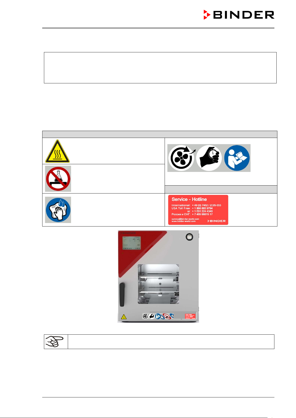
Figure 3: VDL 115 with MB2 controller ....................................................................................................... 41
Figure 4: Triangular instrument box (controller housing) with MB2 program controller and USB interface 42
Figure 5: Chamber rear (example: VDL 115) .............................................................................................. 42
Figure 6: Rear connection panel VDL wit h optio ns ..................................................................................... 43
Figure 7: Area classification of the closed chamber (view without housing, insulation, heater and outer
chamber) ...................................................................................................................................... 45
Figure 8: Area classification in the surroundings of the chamber (schematic representation, standard
device) .......................................................................................................................................... 46
Figure 9: Area classification in the surroundings of the chamber during operation (example) ................... 47
Figure 10: Operating the expansion racks .................................................................................................. 53
Figure 11: Mounting the pressure regulator on the chamber rear .............................................................. 55
Figure 12: Compressed air connect ion on t he pressure regulator .............................................................. 56
Figure 13: VDL mounted on pump module ................................................................................................. 57
Figure 14: Pump module, rear view (example size 115) ............................................................................ 57
Figure 15: Position of the Vacuum connection (6) on the chamber rear (example size 56) ....................... 59
Figure 16: Vacuum pump VP 4 (MZ2C EX) ................................................................................................ 61
Figure 17: Variable length of the tilt protecti on ho lder depe nd ing on the ben d .......................................... 65
Figure 18: Possibilities of grounding (schematic representation) ............................................................... 66
Figure 19: Mounting the grounding cab le on the VDL ................................................................................. 67
Figure 20: Normal display of the MB2 program controller (sample values) ................................................ 74
Figure 21: Operating functions of the MB2 controller in normal display (example values) ......................... 75
Figure 22: Pressure regulator and sweeping plug for compressed air sweeping on the chamber rear ..... 86
Figure 23: analog pressure display (manometer) for compressed air sweeping on the chamber front ...... 86
Figure 22: Pressure regulator with defined setting at the upper stop ......................................................... 87
Figure 24: Schematic timing of the drying process and drying monitoring ............................................... 103
Figure 25: Pressure regulator and sweeping plug for compressed air sweeping on the chamber rear ... 160
Figure 26: Connection cable on the “Analog output” (3b) connection...................................................... 161
Figure 26: SUB-D socket for the analog outputs option ............................................................................ 161
Figure 29: Measuring connection (12) with measuring access port .......................................................... 162
Figure 29: Connection cable on the “Object temperature input” connection (3a) ..................................... 162
Figure 29: Plug connection between measuring access port and Lemo socket ....................................... 162
Figure 29: Cable connection of the option al Pt 100 sensor ...................................................................... 162
VDL (E3.1) 10/2020 Page 7/196
Page 8
Dear customer,
For the correct operation of the VDL vacuum drying oven, it is important that you read this operating manual
completely and caref ully and obser ve all instruc tions as ind icated. Failur e to read, understand an d follow
the instructions may result in personal injury. It can also lead to damage to the chamber and/or poor equipment performance.
1. Safety
1.1 Personnel Qualification
The chamber m ust only be installed, tested, and start ed up by personn el qualified for as sembly, startup,
and operation of the chamber with additional skills in explosion protection (ATEX). Qualified personnel are
persons whose professional education, knowledge, experience and knowledge of relevant standards allow
them to assess, carry out, and identify any potential hazards in the work assigned to them. They must have
been trained and ins truc ted , and be auth or ized , to w or k on the chamber. This incl udes a bas ic knowledge
of explosion protection ( ATEX training), instr uction based on the r isk assessment by the op erator (chap.
2.2) and knowledge of the Operating Instruction by the operator.
The device shall only be op erated b y laborator y personne l especiall y trained for this purpose and fam iliar
with all precautio nary measures required for working acc. to ATEX Directive 2014/37/EU . Observe the
national regulations on minimum age of laboratory personnel.
1.2 Operating manual
This operating m anual is part of the components of deliver y. Always keep it hand y for reference in the
vicinity of the chamber. If selling the unit, hand over the operating manual to the purchaser.
To avoid injuries a nd pr oper ty dam age obser ve t he saf et y instruct ions of the oper atin g m anual. Fa ilure t o
follow instructions and safety precautions can lead to significant risks and to the loss of explosion protection.
DANGER
Explosion hazard due to failure to observe the instructions and safety precautions.
Serious injuries and chamber damage. Risk of death.
Observe the safety instructions in this Operating Manual.
Follow the operating procedures in this Operating Manual.
Carefully read the complete operating instructions of the chamber prior to installing and
using the chamber.
Keep the operating manual for future reference.
Make sure that all persons who use the chamber and its associated work equipment have
read and understood the Operating Manual.
This Operating Manu al is supplemented a nd updated as needed. Alwa ys use the most recent version of
the Operating Manual. W hen in doub t, call the BIND ER Serv ice Hotline f or inform ation on the up-to-dateness and validity of this Operating Manual.
VDL (E3.1) 10/2020 Page 8/196
Page 9

1.3 Legal considerations
This operating m anual is for inform ational purposes only. It co ntains information f or correct and safe i nstalling, start-up, opera tion, decommissioning, cl eaning and maintenance of the product. The content of
this operating manual takes into account the applicable regulatory requirements and the latest technology.
Note: the contents and the product described are subject to change without notice.
Understanding and observing the instructions in this operating manual are prerequisites for hazard-free use
and safety during operation and maintenance. Images are to provide basic understanding. They may deviate from the actual vers ion of the chamber. The actu al scope of delivery can, d ue to optional or special
design, or due to recent tec hnical chan ges, deviate f rom the information and illus trations i n these instruc tions this operating m anual. In no event shall BINDER be he ld liabl e for an y damages , direc t or inc identa l
arising out of or related to the use of this manual.
This operating manual can not cover all conce ivable applications. If you would lik e additional information,
or if special problem s arise that are not suff iciently addressed in th is manual, please ask your dealer or
contact us directly, e.g. by phone at the number located on page one of this manual.
Furthermore, we emphasize that the contents of this operating manual are not part of an earlier or existing
agreement, descriptio n, or l ega l rel ati ons h ip, nor d o they modify such a relati ons h ip. All o bl iga tio ns on t he
part of BINDER derive from the respective purchase contract, which also contains the entire and exclusively
valid statement of warranty administration and the general terms and conditions, as well as the legal regulations valid at the time the contract is concluded. T he statements in this manual neither augment nor
restrict the contractual warranty provisions.
Furthermore, relevan t national and international reg ulations on occupational saf ety apply. The operator
must know, compl y with, and implem ent these requir ements. In partic ular, this includ es the provisions of
ATEX Operational Directive 19 99/92/ EC (“ATEX 137”) (implem ented for Germ any in the In dustrial Safet y
Regulation (BetrSichV) and the Ordinance on Hazardous Substances (GefStoffV)). The operator is responsible for choosing suitabl e wor k equipm ent for t he are as c lassif ied as ex plos ion h azards and f or i nstalli ng
and operating equipment in accordance with respective requirements.
Limitation of liability
BINDER GmbH is not liable for any damage arising from the following causes:
• Non-observance of Instruction Manual
• Improper use
• Improper installation, setup, maintenance, repair
• Inspections not being performed (testing before ini tial commissioning, recurring tests, tes ting before
recommissioning
• Negligence or willf ul int ent
• Incorrect response to malfunctions
• Assignment of improperly or insufficiently trained personnel
• Technical changes and modifications made by the operator and not approved by the manufacturer
• Use of non-approved accessories and replacement parts
We reserve the right to technical changes as part of improvements to operating characteristics and further
development.
Have repairs performed only by experts authorized by BINDER. Repaired chambers must comply with the
quality standard sp ecified by BIND ER. In par ticular, carr y out an ins pectio n befor e recomm issioning after
maintenance or rep airs. Thes e can onl y be perf ormed by the manuf acturer or speciall y trained p ersonnel
(in Germany: Qualified Persons per BetrSichVO).
VDL (E3.1) 10/2020 Page 9/196
Page 10
1.4 Structure of the safety instructions
In this operating manual, the following safety definitions and symbols indicate dangerous situations following the harmonization of ISO 3864-2 and ANSI Z535.6.
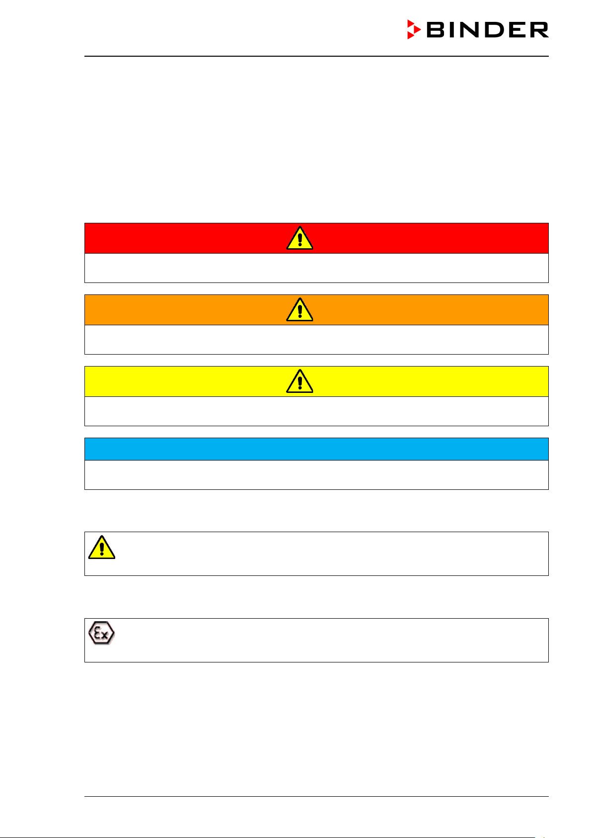
1.4.1 Signal word panel
Depending on the probability of serious consequences, potential dangers are identified with a signal word,
the corresponding safety color, and if appropriate, the safety alert symbol.
DANGER
Indicates an imminently hazardous situation that, if not avoided, will result in death or serious (irreversible) injury.
WARNING
Indicates a potentially hazardous situation which, if not avoided, could result in death or serious (irreversible) injury.
CAUTION
Indicates a potentially hazardous situation which, if not avoided, may result in moderate or minor (reversible) injury.
NOTICE
Indicates a potentially hazardous situation, which, if not avoided, may result in damage to the product
and/or its functions or to property in its proximity.
1.4.2 Safety alert symbol
Use of the safety alert symbol indicates a risk of injury
Observe all measures that are marked with the safety alert symbol in order to avoid death or
injury.
1.4.3 Explosion protection symbol
Use of the explosion protection symbol warns against explosion hazards.
Observe all measures in this operating manual to avoid the formation of explosive atmosphere
as well as explosions.
VDL (E3.1) 10/2020 Page 10/196
Page 11
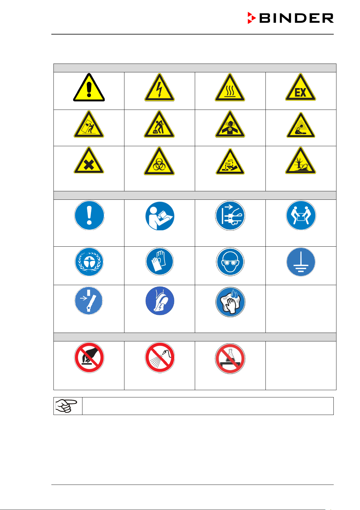
Warning signs
Danger of injury
Electrical hazard
Hot surface
Explosive atmosphere
Stability hazard
Lifting hazard
Inhalation hazard
Suffocation hazard
or chemical burns
Mandatory action signs
plug
Environment protection
Wear eye protectors
Ground before use
(antistatic shoes)
only
Prohibition signs
on the chamber
1.4.4 Pictograms in this manual
Harmful substances
Mandatory regulation
Biohazard
Read operating
instructions
Wear protective gloves
Risk of corrosion and /
Disconnect the power
Pollution Hazard
Lift with several persons
Release before mainte-
nance or repairs
Do NOT touch
Information to be observed in order to ensure optimum function of the product.
Wear ESD shoes
Do NOT spray with
water
Wipe with damp cloth
Do not place anything
VDL (E3.1) 10/2020 Page 11/196
Page 12
Safety labels
Service label
1.4.5 Word message panel structure
Type and cause of hazard.
Possible consequences.
∅ Instruction how to avoid the hazard: prohibition
Instruction how to avoid the hazard: mandatory action
Observe all other n otes and informat ion not necessarily em phasized in the sam e way, in order to a void
disruptions that could result in direct or indirect injury or property damage.
1.5 Localization / position of safety labels on the chamber
The following labels are located on the chamber door:
Hot surface
Do not place anything on the chamber
Wipe surfaces with damp cloth only
Observe sweeping time, read operating manual
Figure 1: Position of labels on the chamber (example)
Keep safety labels complete and legible.
Replace safety labels that are no longer legible. Contact BINDER Service for these replacements.
VDL (E3.1) 10/2020 Page 12/196
Page 13
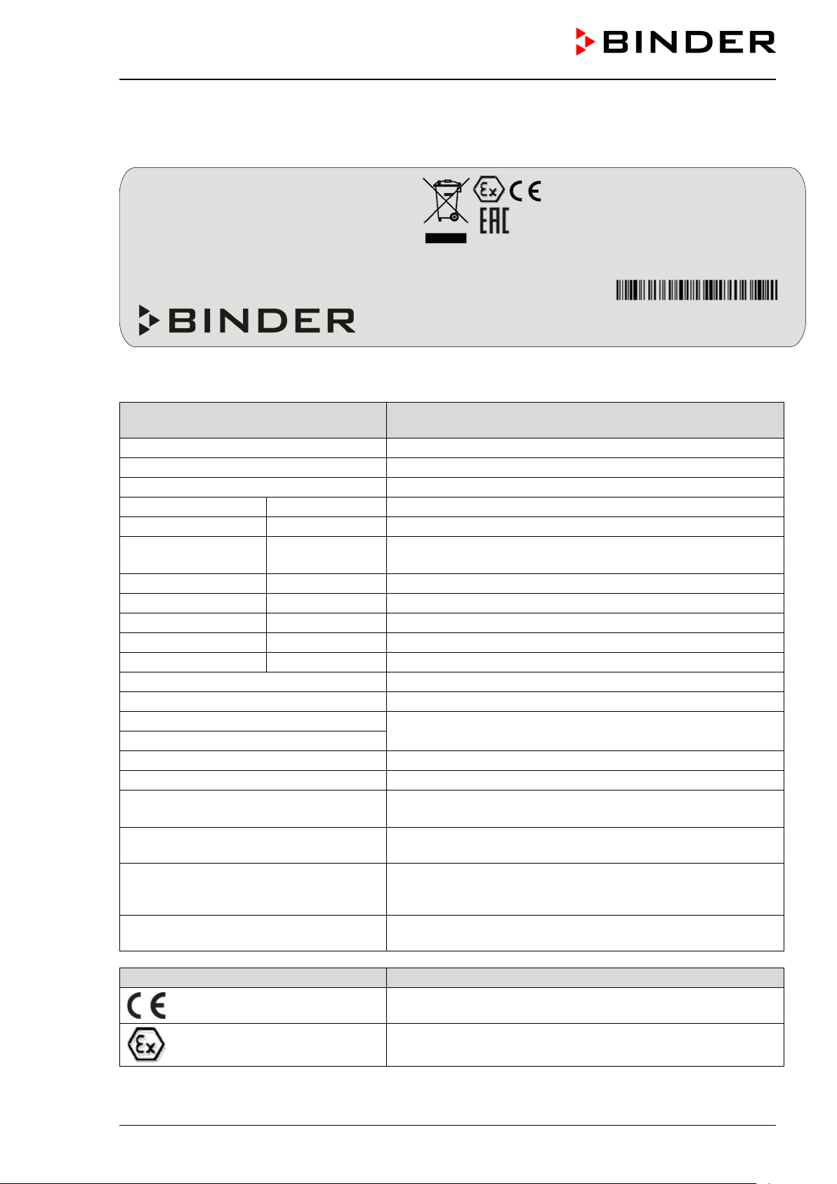
Indications of the type plate
(example)
Information
BINDER
Manufacturer: BINDER GmbH
VDL 115
Model designation
Vacuum Drying Oven
Chamber name: Vacuum drying oven
Serial No.
000000000000
Serial No. of the chamber
Built
2020
Year of construction
110 °C
230 °F
IP protection
20
Type of IP protection acc. to standard EN 60529
Temp. safety device
DIN 12880
Temperature safety device acc. to standard DIN 12880:2007
Class
2.0
Class of temperature safety device
Art. No.
9630-0011
Art. No. of the chamber
Project No.
---
Optional: Special application acc. to project no.
1,60 kW
Nominal power
7,0 A
Nominal current
230 V / 50 Hz
230 V / 60 Hz
1 N ~
Current type
Explosion proof inner chamber
Explosion proof inner chamber
Ex classification acc. to 2014/34/EU
Ex II 2/3/- G IIB T3 Gb/Gc/- X
Ex classificatio n according to ATEX Directive 2014/34/EU
Max. temp. of inner chamber surface in
cat. 2: +160 °C
Maximum temperature of the inner chamber surfaces:
160 °C / 320 °F (Device category 2)
Maximum temperature of the outer surface of the preheating
3)
Temperature class acc. to IEC 60079-0 for the entire chamber
Symbol on the type plate
Information
Nominal temp.
110 °C
1,60 kW / 7,0 A
EXPLOSION PROOF INNER CHAMBER
TEMP. CLASS T3
230 V / 50 Hz
230 V / 60 Hz
1 N ~
VACUUM DRYING OVEN
BINDER GmbH
www.binder-world.com
VDL 115
1.6 Type plate
Position of type plate: left chamber side (seen from front), at the bottom right-hand.
IP protection
Safety device
Class
Art. No.
Project No.
Built
230 °F
20
DIN 12880
2.0
9630-0011
2020
Nominal temperature
Im Mittleren Ösch 5
78532 Tuttlingen / Germany
E3.1
Figure 2: Type plate (example of VDL 115)
Nominal temperature
EX CLASSIF. ACC. TO 2014/34/EU
EX II 2/3/ - G IIB T3 GB/GC/- X
TEMP. OF INNER CHAMBER
MAX.
SURFACE IN CAT 2: +160 °C
MAX. TEMP. OF HEATING CHAMBER
SURFACE IN CAT 3: +195 °C
Serial No. 00000000000000
Made in Germany
Max. temp. of heating chamber
surface in cat. 3: +195 °C
Temp. class T3
VDL (E3.1) 10/2020 Page 13/196
Nominal voltage +/- 10% at the indicated power frequency
chamber (outer chamber): 185 °C / 365 °F (Device category
CE conformity marking
Explosion protection symbol. Ex classification acc. to ATEX
Directive 2014/34/EU
Page 14

Symbol on the type plate
Information
Electrical and electronic equipment manufactured / placed on
the market in the EU after 13 August 2005 and to be disposed of in a separate collection according to Directive
2012/19/EU on waste electrical and electronic equipment
(WEEE).
The chamber is certified according to Customs Union Technical Regulation (CU TR) for the Eurasian Economic Union
(Russia, Belarus, Armenia, Kazakhstan Kyrgyzstan).
1.7 Safety instructions on installing and operating the vacuum drying oven
With regard to o perating the vacuum dr ying o ven VDL an d to t he i nstal lation locat ion, p lease o bser ve t he
relevant national regulation s (for Germ any in partic ular: DGUV guidelines 213-850 o n safe work ing in laboratories, issued by the employers’ liability insurance association; Industrial Safety Regulation (BetrSichV); Ordinance on Hazardous Substances (GefStoffV); Technical Regulations on Industrial Safety and
Health (TRBS 1201 Part 1).
The central element of the Industrial Safet y Regulation is the risk ass essment performed by com petent
personnel which enables an employer to evaluate risks that may arise before using work equipment and to
derive necessary and suitable tests and measures.
Explosion protection plan
The explosion protection plan to be created by the operator r eprese nts the e ntiret y of the tech nica l and
organizational measures for explosion protection determined and specified on the basis of the risk assessment. In accordance with ATEX Operational Directive 1999/92/EC, these measures serve
• to prevent the formation of or to limit explosive atmospheres or to limit hazardous explosive mixtures
• to avoid the combustion of explosive atmospheres
• to limit the spread of an explosion and to minimize its effects on personnel in order to ensure the health
and safety of employees
The explosion pro tection d ocum ent serves t o docum ent the results of the r isk as sessm ent in accor dance
with § 6 Para. 9 GefStoffV (for Germany).
BINDER Gm bH is onl y responsible f or the safet y features of the cham ber provided s killed elec tricians or
qualified personnel authorized by BINDER perform all maintenance and repair, and if components relating
to chamber safety are replaced in the event of failure with original spare parts.
To operate the cham ber, use onl y original BIND ER acc essories or acc essories from third-part y suppliers
authorized by BINDER. The user is responsible for any risk caused by using unauthorized accessories.
1.7.1 Safety instructions on installation and ambient conditions of the chamber
Familiarize yourself w ith the loca l conditions , particul arly alloca tion to a def ined potent ially exp losive area
(zones) and the according technical safety requirements. During installation, commissioning and operation
of the vacuum drying oven and the connected vacuum pump or in-house vacuum supply, always follow the
requirements defined by the classification of the installation site.
VDL (E3.1) 10/2020 Page 14/196
Page 15
1.7.1.1 Aeration / ventilation of the installation site
NOTICE
Danger of overheating due to lack of aeration.
Damage to the chamber.
∅ Do NOT install the chamber in unventilated recesses.
Ensure sufficient ventilation for dispersal of heat.
Observe the prescribed minimum distances when installing the chamber (chap. 5.1)
The vacuum drying ovens wer e construc ted in acc ordance with the applicab le VDE reg ulations a nd were
routinely tested in accorda n c e with VD E 041 1-1 (IEC 61010-1). The production underlies an internal monitoring according to ATEX Directive 2014/34/EU appendix VIII.
For the user there is no risk of temporary overvoltages in the sense of EN 61010-1:2010.
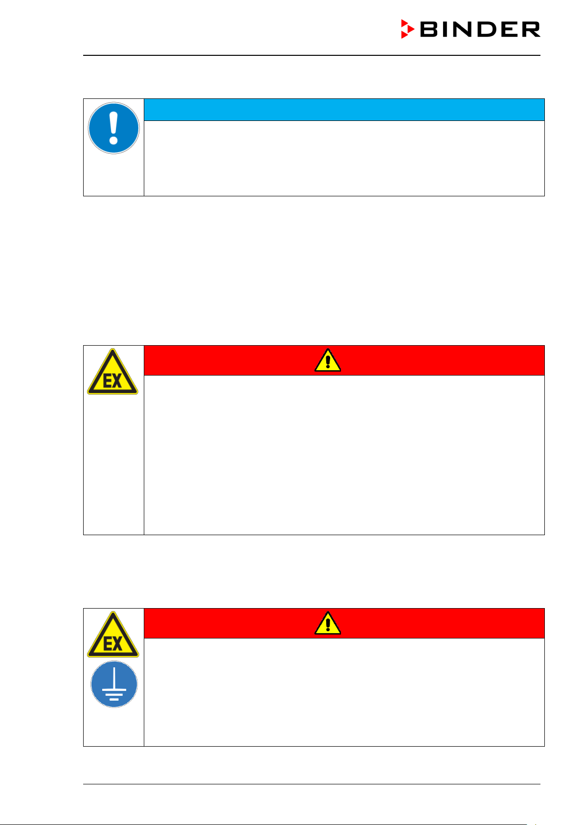
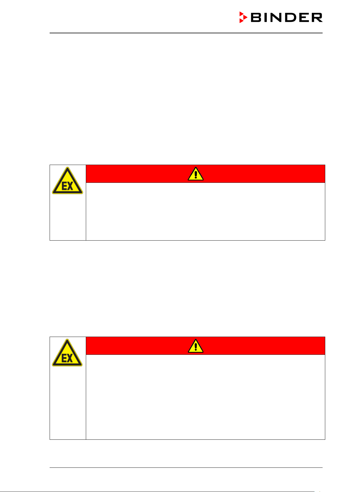
1.7.1.2 No installation in potentially explosive areas of Zone 1 or 0
Even when the equipment is used properly, there exists a residual risk of explosion that cannot be excluded,
particularly in relation to the environm ent of the chamber. T o minimize this risk , strictly observe the legal
regulations about how to select an appropriate location. Do not install and operate the vacuum drying oven
VDL in occasionally or continuously / for long periods / frequently potentiall y explo s ive areas .
DANGER
Explosion hazard due to combustible dusts or explosive mixtures in the vicinity of
the equipment.
Serious injury or death from burns and / or explo sion pressure.
∅ Do NOT operate the chamber in in occasionally or continuously / for long periods / fre-
quently potentially explosive areas. It is not intended for installation in a zone 1 or 0.
KEEP combustible dusts AWAY from the equipment
Make sure that air-solvent mixtures are NOT occasionally or continuously / for long pe-
riods / frequently in the vicinity of the equipment.
Reliably prevent spreading of an explosive atmosphere to unprotected areas (see chap.
3.5).
Strictly observe the relevant legal regulations about how to select an appropriate loca-
tion.
1.7.1.3 Equipotential bonding according to the grounding concept
The walkable install ation and o perating surf ace of the c hamber mus t be conductive. T his installat ion and
operating surface must be connected to the vacuum drying oven according to the grounding concept (chap.
6.8). Cyclic measurements of the equipotential bonding are required.
DANGER
Explosion hazard by electric sparking due to missing or improperly implemented
equipotential bonding.
Serious injury or death from burns and / or explo sion pressure.
Connect all equipment elements in the installation and operating area (VDL / pump
module / pump) with the conductive surface and/or with each other. Proceed according
to the grounding concept (Chap. 6.8).
Measure the equipotential bonding prior to commissioning the equipment.
Provide cyclic measurements of the equipotential bonding.
VDL (E3.1) 10/2020 Page 15/196
Page 16
1.7.1.4 Accessibility to the disconnection from the power grid
To completely separat e the cham ber from the power supp ly, you mus t disconnect the power plug. Install
the chamber in a way that the power plug is easily accessible and can be easily pulled in case of danger.
The chamber’s power plug is unprotected. The electrical connection must therefore be established outside
a zone.
1.7.1.5 Technical ventilation (extraction)
The operator shall provid e active ex tractio n (technic al venti lation ac c ord ing to c ou ntry-specific regulations
(TRBS 2152 Part 2 for Ger many) before comm issioning the chamber . Extraction must include t he entire
installation area of the vac uum drying oven and a vacuum pump. Observe the area classif ication in the
surroundings of the chamber (chap. 3.5.3). Extraction must be active during the entire chamber operation.
Operation, loading and unloading of t he load ing m ater ial an d rem oval of the f illed conde nsate catc hpot of
the pump must always take place under technical ventilation. If the technical ventilation fails, automatically
switch off power to the chamber.
This will prevent spreading of an explosive atmosphere to unprotected areas (see chap. 3.5).
DANGER
Explosion hazard due to the spread of an explosive atmosphere to unprotected areas and ignition due to electric sparking or hot surfaces.
Serious injury or death from burns and / or explo sion pressure.
Provide active suction (technical ventilation according to country-specific regulations
(TRBS 2152 Part 2 for Germany) prior to commissioning the chamber.
Extraction must include the entire installation area of the vacuum drying oven.
Make sure that the chamber is automatically turned off if the technical ventilation fails.
1.7.2 Safety instructions on compressed air supply
Before starting / restarting the chamber, the electrical installation room, preheating chamber, and controller
housing (triangular instr ument box) m us t be swept with c om press ed air with m axim um overpress ure for a
defined time (chap. 9.3).
Sweeping the area for electrical equipment, the preheating chamber and controller housing must take place
with an overpressure of at least 25 Pa (recommendation: >40 Pa) during the entire operation of the vacuum
drying oven. Also after termination or cancellation of the drying process, continued sweeping for at least 10
minutes is recommended.
An inlet pressure of 2 bar must be provided for compressed air sweeping. T he c ompressed air supply line
provided by the operator m ust be equipped with a monitoring device whic h clearly indicates a drop and
increase in the inlet pressure outside the permissible tolerance of ± 0.2 bar.
DANGER
Explosion hazard by solvent-containing air penetrating the electric al area of the
oven or the preheating chamber.
Serious injury or death from burns and / or explo sion pressure.
Make sure that sweeping the area for electrical equipment, preheating chamber, and
controller housing with compressed air for the defined time (chap. 9.3.2) at maximum
overpressure has been done before turning on the chamber.
Make sure that sweeping the area for electrical equipment, preheating chamber, and
controller housing with compressed air with an overpressure of at least 25 Pa (recommendation: >40 Pa) takes place during the entire operation.
Ensure that the operator compressed air supply line is equipped with active monitoring
of the defined inlet pressure.
VDL (E3.1) 10/2020 Page 16/196
Page 17
1.7.3 Safety instructions on vacuum supply
Prior to commissioning the cham ber m ake sure that all r elevant nation al and int ernational r egulations are
observed. Within the European Union, units that will be operated in potentially explosive areas have to meet
the requirements of ATEX Directive 2014/34/EU.
If combustible solvent is introduced i nto the dryin g cham ber, the vacuum pump must be constructed in a
suitable explosion-proof manner.
Observe the safety instructions of the pump manufacturer.
1.7.3.1 Selection and location of a suitable pump
The mixtures extrac ted f r om the inner chamber mus t be carr ie d a wa y m aking sure that there is no da nger
by ignition of these atmospheres. Sparking in t he p ump motor or the switchi ng elements, electrostatic discharges, as well as hot pump parts can ignite solvent vapors in the event of an error. To minimize this risk,
use an ATEX Directive 2014/34/EU com pliant vacuum pump suitable for s uction from Zone 0 or 1 and, if
appropriate, from the zone of its installation site.
Explosion hazard due to the spread of an explosive atmosphere to unprotected
pump parts and ignition due to electric sparking on the pump motor or switching elements, electrostatic discharges, or hot surfaces.
Serious injury or death from burns and / or explo sion pressure.
Use only suitable, explosion-proof pumps. See chap. 6.5.1.
Operate the pump in a stationary position and secure it so it is immobile.
Make sure that the suction line to the vacuum connection (6) of the VDL is fixed and
conductive.
Ensure sufficient solvent condensation, e.g., in an exhaust waste vapor condenser, to
avoid that ignitable solvent concentrations are conducted from the pump. Otherwise,
the exhaust pipe after the pump must be fixed and conductive and suction must be
done in an explosion-proof area.
Ensure equipotential bonding between the pump, the VDL vacuum drying oven and, if
appropriate, the pump module using the connections of the grounding conductors according to the grounding concept (Chap. 6.8).
Confirm that the vacuum pump is designed for a gas inlet temperature corresponding to
the used drying temperature, or take appropriate measures to cool down the extracted
vapor before it enters the vacuum pump.
Use ATEX compliant vacuum pumps providing an integral protective device for the
pump OR Install a current-dependent, delayed protective device for the pump (for the
triggering time of this protective device, see the manufacturer’s specifications). The protective and monitoring device must not be able to turn on independently again or be released.
Use ATEX compliant vacuum pumps providing an integral explosion proof switch OR
make sure that the switch gear box is either installed outside the hazardous area or that
it is explosion proof.
The ATEX compliant vacuum pump offered by BINDER provides an integral protective device
for the pump and an integral explosion proof switch.
DANGER
VDL (E3.1) 10/2020 Page 17/196
Page 18
1.7.3.2 Observing the permissible gas inlet temperature
Confirm that the vacuum pum p / vacuum s ystem is designe d for a gas inlet tem perature corresponding to
the used drying temperature, or take appropriate measures to cool down the extracted vapor before it enters
the vacuum pump / vacuum system. If the gas inlet temperature is too high and then becomes even warmer
by compression in th e p um p, th e r es ult ing temperature (of the gas-solvent mixture inside t he pump) could
exceed the solvent’s temperature class and auto-ignition temperature. The ATEX compliant vacuum
pumps offered by BINDER are designed for a gas inlet temperature of 40 °C / 104 °F max. Do NOT
exceed this temperature.
DANGER
Fire and explosion hazard by exceeding th e auto-ignition temperature of the solvent
due to excessive gas inlet temperature
Damage to the vacuum pump. Serious injury or death from burns and / or explosion
pressure.
∅ Do NOT exceed the maximum gas inlet temperature of the pump (ATEX compliant vac-
uum pumps from BINDER: 40 °C).
When operating with a higher set-point temperature take appropriate measures to cool
down the extracted vapor before it enters into to the vacuum pump.
1.7.3.3 Technical Ventilation (extraction)
When manipulating the vacuum pump (removing the filled condensate catchpot of the pump) or in the event
of an error (e.g. drop pi ng o r spil ling the filled condensate c atchpot) spreading of an ex p los ive atmosphere
to unprotected parts of the pump or the vacuum drying oven would be possible.
The operator must pr ovide ac tiv e extr ac tio n (technical ventilation acc ord ing t o c ou ntry-specific regulations
– TRBS 2152 P art 2 f or G e rmany) prior to comm is s ioning an d manipulating the vac uum pump. Extraction
must include the entire installation area of the vacuum drying oven, the pump and, if appropriate, the pump
module. Handling the pump always takes place under technical ventilation.
This will prevent spreading of an explosive atmosphere to unprotected chamber parts other than the defined
area (see Chap. 3.5).
DANGER
Explosion hazard due to the spread of an explosive atmosphere to unprotected
parts of the pump or the vacuum drying oven and ignition due to electric sparking
or hot surfaces.
Serious injury or death from burns and / or explo sion pressure.
Provide active suction (technical ventilation according to country-specific regulations
(TRBS 2152 Part 2 for Germany) prior to commissioning the vacuum pump.
Extraction must include the entire installation area of the vacuum drying oven, the pump
and, if appropriate, the pump module.
When using the pump module, connect an extraction system to the provided exhaust
port as described in the mounting instructions of the pump module (Art. no. 7001-0137).
VDL (E3.1) 10/2020 Page 18/196
Page 19
1.7.4 Safety instructions on the charging material
The temperature class of the inner chamber according to IEC 60079-0 can be T1, T2, or T3. Only introduce
substances with an auto-ignit ion temperature that is h igher than 200 °C / 392 °F. Yo u can use a sol vent
which would form an explosive mixture with air under normal conditions.
If the auto-ignition tem per ature of a solvent contained i n th e drying material is exceeded during the drying
process, there is an imm ediate risk of fire and explosion. This chamber is not sui table to dry substanc es
with an auto-ignition tem perature below 200 °C / 3 92 °F. Substances falling u nder explosion gro up / gas
group IIC are not permitted (e.g. carbon disulfide, hydrogen).
Combustible dusts are gener ally not permitted, neither in the vicinity nor as a load.
DANGER
Explosion hazard due to unsuitable drying material.
Serious injury or death from burns and / or explosion pressure.
∅ Do NOT introduce any substance with an auto-ignition temperaturebelow 200 °C / 392
°F into the chamber
∅ Do NOT introduce combustible dusts into the chamber.
∅ Do NOT introduce any substance which tends towards exothermal decomposition into
the chamber.
∅ Do NOT introduce any substance which comes under the explosive substance law into
the chamber.
∅ Do NOT introduce energy sources such as batteries or lithium-ion batteries into the
chamber.
∅ Do NOT introduce any substance which could lead to release of toxic gases into the
chamber.
Familiarize yourself with the physical and chemical properties of the charging material, as well as the contained moisture co nstit uen t and its beh av ior wit h th e ad dit ion of he at ener gy and changes in pr es s ure. N o
dangerous chemical reactions must occur during the drying process.
DANGER
Fire and explosion hazard caused by chemical reactions with the addition of heat
energy and changes in pressure.
Serious injury or death from burns and / or explo sion pressure.
Make sure that no dangerous chemical reactions of the loading material can occur dur-
ing the drying process.
Familiarize yourself with any potential health risks caused by the charging material, the contained moisture constituent or by reaction products that may arise during the drying process.
Take adequate measures to exclude such risks prior to putting the VDL vacuum drying oven
into operation.
VDL (E3.1) 10/2020 Page 19/196
Page 20
1.7.5 Safety instructions on operating the vacuum drying oven
Note the following points before starting up the oven:
When loading the chamber and possibly at the moment of unloading, also in the context of
intended use, an explosive mixture may form in the working space. Define a safety area of
at least 1m from the chamber front and ensure active extraction (technica l vent ilat i on).
The walkable installation and operating surface of the chamber must be conductive. This
installation and operating surface must be connected to the vacuum drying oven according
to the grounding concept. Cyclic measurements of the equipotential bonding are required.
The operator must ensure an appropriate ventilation of the loading area in front of the
oven front prior to commissioning of the chamber.
Ensure that at no time any solvent vapors could enter in the area of the electrical installa-
tion room, preheating chamber, and controller housing (triangular instrument box).
Provide technical ventilation in the area of the vacuum pump stand, particularly in the areas
of the condensate catchpot (when emptying it) and the exhaust air of the vacuum pump.
The personal protective equipment (PPE) of the operating personnel must be ESD pro-
tected.
Only trained personnel with password authorization may work on the VDL vacuum drying
oven.
DANGER
Electrical hazard by water entering the chamber.
Deadly electric shock.
∅ The equipment must NOT become wet during operation, cleaning, or maintenance.
∅ Do NOT install the equipment in damp areas or in puddles.
Set up the equipment in a splash-proof manner.
DANGER
Electrical hazard due to damage to the equipment
Deadly electric shock.
∅ Do NOT insert any objects, particularly metallic objects, in louvers or other openings or
slots on the chamber
∅ Do NOT operate the chamber if the housing is damaged.
∅ Do NOT operate the chamber if the power cord is dam aged.
Disconnect the chamber from the power supply in case of an obvious malfunction.
CAUTION
Danger of burning when touching the hot inner surfaces during operation.
Burns.
∅ Do NOT touch the inner surfaces or the charging material during and after operation.
VDL (E3.1) 10/2020 Page 20/196
Page 21
The unit must not be operated without compressed air flushing at maximum overpressure and
When operating the VDL vacuum drying oven with inert gas correctly follow the technical ventilation
measures, as described in the DGUV guidelines 213-850 on safe working in laboratories (for Germany).
Do not start up the chamber without active technical ventilation .
During operation with inert gas the chamber is supplied with an oxygen displacing gas (e.g. N2). Inert gases
in high concentrations are hazardous to health. They are colorless and almost odorless and therefore practically imperceptible. I nhalation of inert gases can c ause drowsiness up to respir a t or y arres t. When the O
content of the air decreases below 18%, t here is risk of death f rom lack of oxygen. An y gas that might
escape has to be led out via good room ventilation or a suitable exhaust system.
DANGER
Suffocation hazard due to high concentration of inert gas.
Death by suffocation.
∅ Do NOT set up chambers in non-ventilated recesses.
Make sure that technical ventilation measures are active.
Respect the relevant regulations for handling inert gases.
When decommissioning the vacuum drying oven, shut off the inert gas supply.
2
If solvent-containing a ir penetrates the elec trical area of the ove n or the preheating chamber , explosions
may result.
DANGER
Explosion hazard by solvent-containing air penetrating the electrical area of the
oven or the preheating chamber.
Serious injury or death from burns and / or explo sion pressure.
∅ Do NOT take the air, which will be used to supply the chamber with compressed air,
from a potentially explosive atmosphere.
∅ Ensure that the operator compressed air supply line is equipped with active monitoring
of the defined inlet pressure.
running compressed air flushing with active monitoring of the defined inlet pressure.
Avoid the solvent accumulation in the optional pump module as this would cause the vacuum
module to become an occasionally or continuously / for long periods / frequently potentially explosive area (Zone 0 or 1). The VDL vacuum drying oven located on top of the module is implemented in Device category 3 in regards to its surroundings.
DANGER
Explosion hazard due to operating the oven with material containing solvent that
may be able to form an explosive mixture with air.
Serious injury or death from burns and / or explo sion pressure.
Follow the measures listed below for operation with solvent-containing materials that
can form an explosive mixture with air.
VDL (E3.1) 10/2020 Page 21/196
Page 22

for a
and must be monitore d at the manometer on the
from the safet y specific ations of the solve nt. In the c ase
After termination of the dr ying
Unload the loading
at the safety spec ifications of the s olvent. I n the case of sol vent m ixtures, use
If the following prec aut ions are not followed, t he v apors resulting from heating of the sol vent c an i gn ite o n
the hot walls of the inner chamber
Required measures for operation with solvent-containing materials that can form an explosive mixture with air:
• Sweep the ar ea for electric al equipment, preheat ing chamber and c ontroller housing
defined time (chap. 9.3.2) prior to start-up with compressed air with maximum overpressure.
Subsequent sweeping of the area for electrical equipment, preheating chamber and controller housing with an o verpressure of at least 25 Pa (rec ommendation: >40 Pa) m ust take
place during the entire op erating cycle
chamber front. In addition, monitoring of the defined inlet pressure (2 bar) of the compressed
air sweeping is required.
• Only after completing the defined sweeping time, put the chamber in operation.
• Take the auto-i gnitio n tem perature
of solvent mixtures , use the auto-i gnition tem perature of the mater ial with the lo west autoignition temperature. Make sure that the auto-ignition temperature is above 200 °C.
• Enter the temperature set-point (drying temper ature) on the controller.
• Set the safety controller (temperature limiter class 2). Recommended setting: safety control-
ler mode “Limit”, safety controller value approx. 5 °C above the set-point.
• During the dr ying process, use on ly those solvents f or which the auto-i gnition tem perature
has been entered.
• Make sure that the technical ventilation is active. Make sure that the compressed air sweeping is active and that the defined inlet pressure is monitored. Bring in the material to be dried.
• Start the dr ying process. The heat ing unit is only released when a pressure threshold of
100 mbar is reached.
• Make sure that sweeping the area for electrical equipment, preheating chamber and controller housing with at least 25 Pa overpressure (see manometer display) takes place during the
entire operating cycle. Recommended value: >40 Pa.
• The duration of the dr ying process can be det erm ined by m eans of the press ure displ ay on
the controller. When the pressure drops to the set-point, the drying process is finished.
• Make sure that the technical ventilation is active. Make sure that the compressed air sweeping is active an d that the def ined in let pres sure is monitored.
process, ventilate the vacu um dr ying oven with am bient air or inert g as .
material and turn off the oven.
• Sweep the area for electrical equipment, the preheating chamber, and the controller housing
(triangular instrument box) at least 10 minutes with compressed air (recommended).
• Make sure that the technical ventilation is active when emptying the condensate catchpot of
the vacuum pump.
• Make sure that sweeping the area for electrical equipment, preheating chamber and controller housing with at least 25 Pa overpressure (see manometer display) is active when emptying the condensate catchpot of the vacuum pump. Recommended value: >40 Pa.
• Before starting a ne w drying process with a different solvent, check again the auto-ignition
temperature
the auto-ignition temperature of the material with the lowest auto-ignition temperature. Make
sure that the auto-ignition temperature is above 200 °C.
VDL (E3.1) 10/2020 Page 22/196
Page 23
1.8 Ex classification of the chamber and immediate surroundings
The VDL vacuum drying oven is an assembly in the sense of ATEX Directive 2014/34/EU with the following
Ex classificatio n:
II 2/3/- G IIB T3 Gb/Gc/- X
Explanation:
II Use of the device above ground
2 Device category 2 per ATEX Directive 2014/34/EU
Suitability for areas in which explosive atmospheres may occur occasionally.
Inner chamber (drying chamber), tubing / line to the vacuum pump, areas inside the vacuum
pump. See images of the areas in Chap. 3.5.
3 Device category 3 per ATEX Directive 2014/34/EU
Suitability for areas in which explosive atmospheres may occur, on a rare and temporary basis:
The entire device, with the exception of the device plug, is designed in Device cat egor y 3 in
relation to the environment
Pt 100 controller sensor, Pt 100 heating sensor
Surrounding of the chamber, including loading area and outer side of the preheating chamber
(outer chamber), area of installation of the vacuum pump, pump module. See images of the
areas in Chap. 3.5.
- No category per ATEX Directive 2014/34/EU
Device power plug (unprotected device area).
With optional analog output: Plug connection of the analog output
The device power plug and the plug connection of the optional analog output are unprotected.
The electrical connection and the optional plug connection of the optional analog outp ut must
therefore be established outs ide a zone.
See images of the areas in Chap. 3.5.
G Device category G per ATEX Directive 2014/34/EU
Gas: Do not introduce combustible dust into the chamber or allow combustible dusts to be
present in the vicinity of the chamber.
IIB Equipment group IIB
Substances falling under Gas group / Explosion group IIA or IIB are permitted.
Substances falling under Gas group / Explosion group IIC are not permitted.
T3 Temperature class of the inner chamber: T3 acc. to IEC 60079-0
Materials of temperature classes T4, T5, and T6 are not permitted. Introduce into the chamber
only materials whose auto-ignition temperature exceeds 200 °C / 392 °F
Gb Equipment protection level (EPL) Gb acc. to EN IEC 60079-0 / EN ISO 80079-36
Suitability for areas in which explosive atmospheres may occur occasionally.
Inner chamber (drying chamber), tubing / line to the vacuum pump.
Gc Equipment protection level (EPL) Gc acc. to EN IEC 60079-0 / EN ISO 80079-36
Suitability for areas in which explosive atmospheres may occur on a rare and temporary basis
(fault):
Chamber areas flushed with compressed air: Electrical installation area, electrical connection
of the heater, preheating chamber between the inner and outer chamber with heater tubes
(without electrical connections) and safety temperature limiter (TL
- No equipment protection level (EPL) Gc acc. to EN IEC 60079-0 / EN ISO 80079-36
Device power plug, plug connection of the optional analog output (unprotected device area)
VDL (E3.1) 10/2020 Page 23/196
Page 24
X Specific operating conditions:
• Technical ventilation required
• Equipotential bonding
• Sweeping the area for electrical equipment, preheating chamber, and controller housing be-
fore start-up and during operation
• Ambient temperature during operation: +18 °C up to +32 °C.
• Use only humid cloths to wipe the chamber.
The “VDL vacuum drying oven” assembly includes the following components and devices in the
sense of the ATEX directive 2014/34/EU:
• Inner chamber (interior for drying material): Container, not a device in the sense of the ATEX directive
2014/34/EU)
It is a purely mechanical component with no risk of ignition. No classification.
• Outer chamber (l imitation of the preheating cham ber to the outside): Container, not a de vice in the
sense of the ATEX directive 2014/34/EU)
It is a purely mechanical component with no risk of ignition. No classification.
• Control (controller)
The controller is loc at ed in the o v erpr es sur e-swept controller housing (instrument triangle). No classifi-
cation.
• Safety temperature limiter (TL): thermal switch (bim etal switch) for temperature monitoring, which
leads to the heating being switched off, and a self-holdin g circuit, which is reset by disconnec ting and
reconnecting the power plug. No classification
The thermal switch is located in the overpressure-swept preheating chamber. The self-holding circuit is
located in the overpressure-swept electrical installation area.
• Pt 100 controller sensor and heating sensor
Both sensors are located on the heating piping (zone 2 possible)
Ex [ic] Ignition protection Intrinsic safety “I” per EN IEC 60079-11
Mechanical component
Equipment protection level: Increased protection “ic”, suitable for placement in Zone 2
II 3 G Ex ic IIB T3 Gc
• Optional Object temperature sensor (simple equipment) with barrier (isolation amplifier)
Ex [ib] Ignition protection Intrinsic safety “I” per EN IEC 60079-11
Equipment protection level: high protection "ib", suitable for placement in Zone 1 (chamber
interior) or 2
II 2 G Ex ib IIB T3 Gb
• Pressure sensor with barrier (isolation amplifier)
Ex [ib] Ignition protection Intrinsic safety “I” per EN IEC 60079-11
Equipment protection level: high protection “ib”, suitable for placement in Zone 1 (chamber
interior) or 2
II 2 G Ex ib IIB T3 Gb
• Pressure limit switch and relay, 100 mbar
It is located in the overpressure-swept electrical installation area. No classification
VDL (E3.1) 10/2020 Page 24/196
Page 25
• Power plug: Connection outside of a zone required
No classification, unprotected.
• Plug connection of the optional analog output: Connection outside of a zone required
No classification, unprotected.
• Electrical installation area, controller housing and heater area (preheating chamber) between the
inner and outer chamber: enclosure (overpressure, sweeping with compressed air)
Ex pzc Ignition protection Pressurized enclosure “p” per EN IEC 60079-2
Equipment protection level: Increased protection "pzc", suitable for use in Zone 2 (chamber
housing as protection against an explosive atmosphere in the event of a fault)
II 3 G Ex pzc IIB T3 Gc
1.9 Intended use
Following the instructions in this operating manual and conducting regular maintenance work
(chap. 25) are part of the intended use.
Any use of the chambers that does not comply with the requirements specified in this Operating
Manual shall be considered improper use.
Other applications than those described in this chapter are not approved.
Use
VDL vacuum dr ying ovens are s uitable f or drying and heat treatm ent of solid or nonf lamm able pulveri zed
charging material, as well as bulk material, using the supply of heat under vacuum.
During this process, the contained solvent may be able to form an explosive mixture with air under normal
conditions. Ignition of an explos ive atmos phere is preven ted in the VD L vacuum drying ovens b y various
safety measures. T he maximum dr ying temperature li es by a standard s afety factor be low the max imum
permitted auto-ignit ion temperature. The drying tem perature must lie belo w the sublimation point of the
loading material.
The VDL vacuum drying ovens are approved for drying of materials with organic solvents. This may cause
unlimited amounts of solvents to app ear tem por aril y. The cham bers are equipp ed w ith an expl osion-proof
inner chamber.
The VDL vacuum drying ovens are not intended for installation in a Zone 1 or 0. The chamber must not be
installed or operated in an occas ionall y or conti nuous ly / f or long p eriods / fr equentl y poten tially explos ive
area. Measures must be taken to prevent the spread of explosive atmospheres to unprotected areas.
The chamber plug (power plug) is unprotected b ecaus e it m ust be disconnec ted in case of an em ergenc y
to completely sep arate the c hamber fr om the power s upply. Therefore, t he electrical connection m ust be
established outside a zone.
Temperature class
The temperature clas s of the inner chamber accor ding to IEC 60 079-0 is T3. It depends on t he m axim um
operation temperatur e ins id e the ov en. The auto-ignition tem peratur e is d eter mined from the safet y specifications of the solvent us e d. In t he cas e of s olven t mixtures, the solvent with the lowest auto-ignition temperature as this is critical.
According to IEC 60079-0 the VDL vacuum drying ovens are NOT suitable for the temperature classes T4,
T5 and T6. Insert only substances with an auto-ignition temperature that is higher than 200 °C / 392 °F.
The information listed on the on the type plate.for explosion protection is essential for classification.
For the Device category, refer to the area classification information on the s ite of installat ion in Cha p. 3.5
.
VDL (E3.1) 10/2020 Page 25/196
Page 26
Requirements for the chamber load
Insert only substances with an auto-i gnition temper ature that is higher than 200 °C / 392 °F into the VDL
vacuum drying ovens. T he c ham bers ar e not suitab le to dr y substanc es with an a uto-ig nitio n tem perature
below 200 °C / 392 °F . Substances f alling under G as group / Explosion gr oup IIC are not perm itted (e.g.
carbon disulfide, acetylene, hydrogen. Substances falling under groups II A and II B may be introduced.
The VDL vacuum drying ovens are NOT suitable for the heat treatment of substances, which tend towards
exothermal decom position, or for m aterials that c ome under the legal definiti on of explos ives. Such substances must not be introduced into the o ven. Dangerous chem ical reactions must not occur during the
drying process. Exo thermal reactions m ust definitely be exclude d. Familiarize yourself with the physical
and chemical proper ties of the lo ading m aterial, as well as the cont ained m oisture c onstituent a nd its behavior with the add ition of heat energy and cha nges in pressure. Fam iliarize yourself with an y potential
health risks caused by the loading material, the contained moisture constituent or by reaction products that
may arise during the temperature process. Tak e adequ ate measures to exclude such r isk s prior to putting
the chamber into operation.
VDL vacuum dr ying ovens are NOT suitable for us e in conjunction with explos ive dust atmospheres or
hybrid mixtures. Combustible dust are generally not permitted.
DANGER
Explosion or implosion hazard and danger of poisoning by introduction of unsuitable loading material.
Serious injury or death from burns and / or explo sion pressure or by poisoning.
∅ Do NOT introduce any substance with an auto-ignition temperature below 200 °C /
392 °F into the chamber.
∅ Do NOT introduce any combustible dust into the chamber.
∅ Do NOT introduce any substance, which tend to exothermic decomposition into the
chamber.
∅ Do NOT introduce any substance, which fall under the explosives law into the chamber
∅ Do NOT introduce energy sources such as batteries or lithium-ion batteries into the
chamber.
∅ Do NOT introduce any substance which could lead to release of toxic gases into the
chamber.
The loading material shall not contain any corrosive ingredients that may damage the machine components made of stainless steel and aluminum. Such ingredients include in particular acids and halides. Any corrosive damage caused by such ingredients is excluded from liability by BINDER GmbH.
Medical devices
The chambers are not classified as medical devices as defined by the Medical Device Directive 93/42/EEC.
Equipotential bonding
Safe grounding ca n av oi d e lectr os tat ic i gn iti on ha zards. The most im portant prote c tive measure is to con-
nect and ground all condu ctive parts. All conductive parts must have electrical potential. T he grounding
plan (Chap. 6.8) must be implemented.
Avoid electrostatic charges. Clean the device only with a damp cloth. Avoid rubbing with nonconductive materials.
VDL (E3.1) 10/2020 Page 26/196
Page 27

Personnel Requirements
Only trained personnel with knowledge of explosion protection and knowledge of the Operating Manual can
set up and install th e c h am ber , star t it up , o per at e, clean, and take it o ut of operation. Serv ice and r ep airs
call for further technical requirements (e.g. electrical know-how), as well as knowledge of the service manual. Follow the requirements for PPE (ESD protection).
Installation site requirements
The chambers are designed for setting up inside a building (indoor use).
Provide active extraction (technical ventilation according to country-specific regulations – TRBS 2152 Part
2 for Germany) on the installation site. It must cover the entire installation area of the VDL and the vacuum
pump stand. Observe the area classification in the surroundings of the chamber (chap. 3.5.3). Suction must
be active during th e entire operatio n of the cham ber and when han dling the condens ate catchpot of the
pump. Suction must be conducted into an explosion-proof area.
Provide compres sed air su ppl y on the ins tallatio n sit e. There must be at least 1.5 bar ov erpres sure in the
supply line. The operator's compressed air supply line must be equipped with active monitoring of the minimum supply pressure (1.5 bar), which shall clearly indicate any drop in pressure below the minimum pressure.
If the technical ventilation fails, automatically switch off power to the device.
VDL vacuum dr ying chambers ar e not intend ed for ins tallation in a Zone 0 or 1. Measures must be t aken
to prevent the spread of explosive atmos pheres to unprotected areas. It must be possible to t urn off the
device immediately in the eve nt of a fault: Pull the power plug or operate e.g. a customer's explosionprotected emergency stop switch.
The requirements described in the Operating Manual for installation site and ambient conditions (Chap. 5)
must be met.
In case of foreseeable use of the chamber there is no risk for the user through the integration of the chamber
into systems or by special environmental or operating conditions in the sense of EN 61010-1:2010. For this,
the intended use of the chamber and all its connections must be observed.
VDL (E3.1) 10/2020 Page 27/196
Page 28

1.10 Foreseeable Misuse
Other applications than those described in chap. 1.8 are not approved.
This expressly incl udes the following misuses (the list is not exhaustive), which pos e risks despite the
inherently safe construction and existing technical safety equipment:
• Non-observance of the Operating Manual
• Non-observance of information and warnings on the chamber (e.g. controller messages, safety identifi-
ers, warning signals)
• Installation , startup, operation, m aintenance and repair b y untrained, insufficientl y qualified, or unauthorized personnel
• Missed or delayed maintenance and testing
• Non-observance of traces of wear and tear
• Operating the equipment without ESD pr o tec ti ve equip ment (e.g., clothing, gloves, shoes)
• Setting down the material to be loaded in the area around or on top of the chamber
• Occurrence of an impermissible zone outside specified areas (see Chap. 3.5)
• Improper termination of the drying process after incorrect loading with inadmissible solvent with too low
an ignition temperature: Ventilating or opening the chamber without waiting for it to cool
• Passing on passwords for the admin level to users
• Emptying the condensate catchpot of the pump without having prior turned off the vacuum pump
• Insertion of materials, which are excluded or not per mitted by this Operating Manual a nd/or are not
permissible according to the Labeling on the type plate.
• Non-compliance with the admissible parameters for processing the respective material.
• Installation, testing, service or repair in the presence of solvents
• Material to be loaded remaining in the chamber after turning off.
• Loading non-approved solvents
• Incomplete ground connections for all system parts in the installation area
• Introduction of rust into the device
• Installation of replacement parts and use of accessories and operating resources not specified and au-
thorized by the manufacturer
• Structural changes to the c hamber without a subse qu ent risk assessment b y th e oper at or' s ATEX representative
• Failure to observe the inspection and maintenance regulations (inspection before initial commissioning,
recurring tests, inspection after maintenance or repairs, qualification of the tester)
• Commissioning after maintenance or repairs without passing the electrical safety test
• Commissioning after maintenance or repairs without passing the explosion protection test.
• Commissioning without correctly and completely grounding in accordance with the grounding plan
• Non-observance of traces of wear and tear, in particular rust
• Installation , startup, op erati on, mainten ance or r epair of the cham ber in absenc e of a ris k asses sment
and operating instructions from the operator
• Deliberate or c ar eles s ha nd lin g of t he c h amber during operation (ex c ept th e p er mitted operation of the
controller).
VDL (E3.1) 10/2020 Page 28/196
Page 29

• Bypassing or c hang in g pr ot ec tive systems, operation of the c hamber without the designated pr otec t ive
systems
• Establishing or disconnecting an electrical connection in the presence of an explosive atmosphere
• Non-observance of messages regarding cleaning and disinfection of the chamber.
• Wiping the chamber with a dry cloth, gen erati ng sta tic c har ge
• Spilling water or cleaning a gent on the cham ber, wate r penetratin g into the cham ber duri ng operation,
cleaning or maintenance.
• Cleaning activity while the chamber is turned on.
• Operation of the chamber with a damaged housing or damaged power cord
• Continued operation of the chamber during an obvious malfunction
• Insertion of objects, particularly metallic objects, in louvers or other openings or slots on the chamber
• Human error (e.g. insufficient experience, qualification, stress, exhaustion, laziness)
To prevent these a nd other risk s from incorrec t operation, th e operator shal l issue operat ing instructi ons
(chap. 2.3). The operator is als o recommended to c reate Standard Oper ating Procedures (SOPs) (chap.
2.6, certain example avoidance measures are provided here).
Explosion hazard due to
formation of explosive
atmosphere in the presence of hot surfaces
during air supply
Normal operation with
high concentration of inert gas
Explosion hazard due to
mechanical spark formation in an explosive
atmosphere by inserting
or removing the slide-in
modules in the presence of an explosive atmosphere
Serious injury or death
from burns and / or explosion pressure.
Danger of suffocation.
Death by suffocation.
Serious injury or death
from burns and / or explosion pressure.
Observe the safety instructions in the operating
manual and follow the instructions for correct air
supply (breaking the vacuum).
The “Manual ventilation” plug (7) must not be removed while the drying process is still running. If
the drying process has not been completed, the
interior of the chamber must have cooled down
sufficiently before air supply and opening the
door.
On the chamber side, gassing with inert gas is
automatically interrupt ed when the ambient pressure is reached.
Observe the warnings in the Operating Manual
and follow the instructions for installation, technical ventilation measures, and decommissioning.
Respect the relevant regulations for handling inert gas.
Observe the warnings in the Operating Manual
and follow the instructions for inserting or removing the expansion racks.
Explosion hazard due to
mechanical formation in
an explosive atmosphere due to rust
Serious injury or death
from burns and / or explosion pressure.
Observe the warnings in the operating instructions and follow the instructions for checking the
chamber and expansion racks for corrosion.
Do not use corroded components. Never allow
rust to permeate into the chamber.
VDL (E3.1) 10/2020 Page 29/196
Page 30

1.11 Residual Risks
The unavoidable design features of a chamber, as well as its proper field of application, can also pose risks
for the user, even during c orr ect operati on. T hese res idual r isk s include hazards which, despit e the in herently safe design, existing technical protective equipment, safety precautions and supplementary protective
measures, cannot be ruled out.
Messages on the chamber and in the Operating Manual warn of residual risks. The consequences of these
residual risks and the measures required to prevent them are listed in the Operating Manual. Moreover, the
operator must take measures to minimize hazards from unavoidable residual risks. This includes, in particular the Operator m easures described in chap. 2. Re sidual hazards are to be t aken into account b y the
operator in their risk assessment. This inc l udes, in par ti cular , issu ing operat ing ins t r uctions .
The following list s ummarizes the hazar ds against which this Operating Manua l and the Service Man ual
warn, and specifies protective measures at the appropriate spots (list is not exhaustive):
• Flames, explosion
Unpacking, Transport, Installati on
• Sliding or tilting the chamber
• Setup of the chamber in unauthorized areas
• Connecting the power plug in unauthorized areas
• Anschluss der Plug connection of the optional analog output in unauthorized areas
• Installation of a damaged chamber
• Installation of a chamber with damaged power cord
• Inappropriate site of installation
• Missing protective conductor connection
• Use of unsuitable pump or vacuum systems
• Improperly connected pump
• Missing or improperly executed equipotential bonding
• Missing or improperly designed technical ventilation in the installation area
• Missing or improperly designed compressed air supply in the installation area, missing monitoring of the
minimum supply pressure of the compressed air supply
Normal operation
• Assem bly errors
• Lack of electrical testing before initial commissioning or recommissioning
• Insufficient or missing technical ventilation (extraction) at the installation area of VDL and pump
• Insuffic ient or missing or not monitored compres sed air sweeping of the electrical i nstallation room,
preheating chamber, and controller housing (triangular instrument box) prior to start-up
• Insuffic ient or missing or not monitored compres sed air sweeping of the electrical i nstallation room,
preheating chamber, and controller housing (triangular instrument box) during chamber operation
• Contact with hot surfaces on the housing
• Contact with hot surfaces in the interior and inside of doors
• Emission of non-ionizing radiation from electrical operating resources
• Use of inert gas in higher concentration (optional)
• Use of unsuitable pump and discharge
VDL (E3.1) 10/2020 Page 30/196
Page 31

• Excessivel y high gas intake tem perature or insufficient cool ing of the extracted vapor before entering
the vacuum pump
• Contact with live parts in normal state
• Operation without supervision
Cleaning and Decontamination
• Explosive atmosphere during cleaning and decontamination
• Electrostatic charges
• Penetration of water into the chamber
• Inappropriate cleaning and decontamination agents
• Enclosure of persons in the interior
Malfunction and Damage
• Continued oper ation of the cham ber during an ob vious malf unction or outag e of the heat er or vacuum
system
• Contact with live parts during error status
• Operation of a unit with damaged power cord
Maintenance
• Maintenance work on live parts.
• Explosive atmosphere during maintenance
• Execution of maintenance work by untrained/insufficiently qualified personnel
• Electrical safety analysis during annual maintenance not performed
• Verification of explosion protection during annual maintenance not performed
• Incorrect and incomplete grounding before recommissioning
Trouble-shooting and Repairs
• Non-observance of warning messages in the Service Manual
• Trouble-shooting of live parts without specified safety measures
• Absence of a plausibility check to rule out erroneous inscription of electrical components
• Performance of repair work by untrained/insufficiently qualified personnel
• Inappropriate repairs which do not meet the quality standard specified by BINDER
• Use of replacement parts other than BINDER original replacement parts
• Electrical safety analysis not performed after repairs
• Verification of explosion protection not performed after repairs
VDL (E3.1) 10/2020 Page 31/196
Page 32

2. Operator responsibil ity, documentation, and measures
This is NOT an exhaustive list of the required measures and documents!
Follow applicable national and int ernat ion al r egu lat ions .
The chamber is int ended for comm ercial use. The op erator must k now, comply with, and implement the
relevant regulations on occupational safety. In particular, this includes the conditions of the Industrial Safety
Regulation 1999/92/E C (Title: Im provement of the Hea lth Protection a nd Safety of Workers W ho May Be
Endangered by Explosive Atmospheres). Known as ATEX 137, this directive was implemented in Germany
through the Industrial Safety Regulation (BetrSichV) and the Ordinance on Hazardous Substances
(GefStoffV).
2.1 Risk assessment / explosion protection document
First, a risk assessment is c arried out to determine the ha zards that are presen t where the chamber is
used due to the working cond itions. When documenti ng the risk assessment, the operator must provide
specific evidence of the hazards posed by explosive mixtures in the explosion protection document.
When creating the explos io n prot ecti on doc ument, follow applicable nat ion al reg u lat ions ( f or Germany: Industrial Safety Regulation (BetrSichV); Ordin ance on H a zardous Subst anc es (Gef Stof f V) ).
In particular, the explosion protection document must indicate
• Determination and evaluation of explosion hazards
• Explosion protection plan
The explosion protection plan to be created by the operator represents the entirety of the technical and
organizational m easures for ex plosion protect ion deter mined and spec ified on th e basis of the risk as sessment. These measures should prevent the formation of hazardous explosive mixtures or to limit or
prevent their ignition. They should also minimize the spread of an explosion and its effects
The explosion protection document serves to document the results of the risk assessment in accordance
with § 6 Para. 9 GefStoffV (for Germany).
• Classificati on as expl os ion pr otec ti on zo nes
• Explosion protection measures
• Cooperation with various companies
• Test findings on explos io n protec ti on and tec hn ic al pr otec ti on m eas ures
2.2 Employee training and protocols
The operator must ensure that all employees have read and understood the Operating Manual.
Before employees use the vac uum drying oven and relate d work equ ipment for the first tim e, the op er ator
must provide them with suff icient and suitable information on the h azards presen ted and meas ures to be
taken in a form and language that is understandable.
This includes the information resulting from the risk assessment:
• Hazards wh en us ing the vacuum dr ying ove n and relat ed work equipm ent, i n par ticular f ire and explosion hazards, functioning of protective devices
• Required protective measures and code of conduct
• Necessity of wearing personal protective equipment, which must be implemented ESD protected.
VDL (E3.1) 10/2020 Page 32/196
Page 33

• Procedure for cleaning and repair work
• Measures for operational interruptions, accidents, and first aid for emergencies
The operator m ust clearly define the responsibilities f or installation, operation, troublesho oting, maintenance, and cleanin g. It must be ensured that untrained personnel ha ve no access to the cham ber and
related work equipment and systems.
The operator must instruct employees with regard to their activity before they begin using the vacuum drying
oven and related wor k equipm ent. Foll owing this, f urther instruc tion m ust be prov ided at re gular i nter vals,
at least once per year. The dat e of each instruction and the names of the instructed persons must be
recorded in writing.
It is essential for safe and secure operation of the device that the user be familiar with the safety plan from
the manufacturer and the explosion protection plan from the operator.
Do not work on the cham ber or in its surroundings, under an y circumstances, after consum ing alcohol,
drugs, and certain medications which may impair the ability to perceive, assess, and react.
2.3 Operating instructions
The measures to av oid ha z ards r esult in g f r om the risk assessment ( Chap. 2.1) are to be specif ie d as Operating instructions. Before employees use the vacuum dr ying oven and re lated work equipm ent f or the
first time, the operator m ust specif y instructi ons for s afe use in one or more oper ating instruc tions. T hese
must comply with regulatory requirements and be verified regularly to ensure that they are up to date.
When creating the operating instructions, f ollow applicable national regulations (for Germ any: Industrial
Safety Regulation (BetrSichV); Ordinance on Hazardous Substances (GefStoffV)).
Keep these operating instructions with the chamber at all times in a place where they are
clearly visible. They must be comprehensible and written in the language of the employees.
2.4 Safety data sheets
A central component of the VDL safet y plan is det ermining the correct auto-ignition temperature of the
solvent used. The corr esponding maximum dr ying temperature (safety temperature) is then determined
according to the information panel “Temperature setting”. In the case of solvent mixtures, using the solvent
with the lowest auto-ignition temperature is essential. The data sheets for the solvents used must therefore
be available at all times. They can be maintained in writing or electronically. If they are stored electronically,
it must be ensured that all employees have access when needed. If an electronic medium is – temporarily –
not available, another source must be found or work must be postponed for this time. (DGUV 4.1)
2.5 Protective equipment
The operator must provide the operating personnel with the necessary protective equipment.
The personal protective equipment (PPE) of the operating personnel must be implemented ESD protected.
When using gloves make sur e that the y are conductiv e. The sam e applies for sh oes and other elements
that can lead to electrostatic charges.
VDL (E3.1) 10/2020 Page 33/196
Page 34
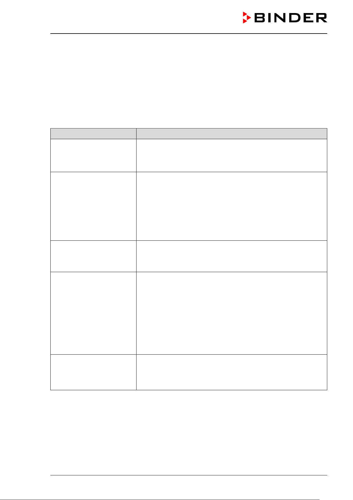
• Ensure knowledge of the Operating Manual
• Prior to each ne w drying procedure chec k again the auto-ignition
• Prior to each ne w drying procedure chec k again the auto-ignition
• Disconnect the power plug and turn off the pump.
• Perform regular maintenance and the prescribed tests of the cham-
2.6 Standard Operating Procedures (SOPs)
The operator is respons ible to determine the correc t auto-ignition temper ature of the solvent. To ensur e
this, creating Standard Operating Procedures (SOPs) is recommended.
In particular, this shou ld pr event t he Re sidual Ris ks due to incorrect operation specified in Chap. 1.11
and the exceeding of the auto-ignition temperature of the solvent.
When creating Standard O perating Proced ures, take into accou nt the inform ation and instructions in this
Operating Manual. T he follo wing are som e examples of these risk s and suggest ions for m easures to be
taken. These are to be c reated, adapted, and sup plemented by the operat or using the risks determ ined
and respective conditions at the installation site.
Risk Measures
Operation of the device by untrained users
• Use only ATEX-trained personnel
• Create operating instruction and standard operating procedures
Use of an unsuitable solvent
with a too low ignition temperature
Cause: Assumption of wrong
solvent
Reloading with a material with
a lower auto-ignition temperature
Termination of the drying process due to inadmissible solvent with a too low ignition
temperature.
Ventilation with ambient air or
opening the still hot chamber
Cause: 2 operating errors: incorrect loading with an inadmissible solvent; improper
Termination of the drying process
temperature with the safety specifications.
• Clearly label the material to be dried to avoid confusion
Information: There is no risk during the proper drying process, since
this takes place in a vacuum. There is only a risk in the event of premature air supply (termination of the drying process.
• Avoid premature air supply. Also observe the instructions in the Operating Manual.
temperature with the safety specifications and the desired drying
temperature. If appropriate, let the chamber cool do wn before reloading
• Let the chamber cool down to room temperature.
• Do NOT remove the “Manual ventilation” plug.
• Only ventilate when the interior temperature has cooled to room
temperature. Only then open the door.
Unnoticed sensor drift or failure of safety devices due to
missing or delayed maintenance and tests
This list is NOT exhaustive. T he risks r esult from the r isk ass essment to be don e by the o perator (Chap.
2.1). The measures mus t be deter m ined b y th e operat or of the dev ice b ased on t he risk s determ ined and
the respective conditions at the installation site.
VDL (E3.1) 10/2020 Page 34/196
ber.
• Create detailed maintenance and testing plans and ensure they are
implemented.
Page 35

Safety controller
2.7 Testing and maintenance
The operator must ensure that the chamber is always in a technically functional state.
Observe the m aintenance intervals spec ified by the manufac turer. If there is above-average str ain, the
intervals must be shortened accordingly.
The operator must regularly verify that the safety-related devices are functioning correctly.
Document tests with resu lts and meas ures that were potenti ally initiated, as well as maintenanc e and re-
pairs, in a system book.
For testing before commissioning, see Chap. 7
For recurring tests and maintenance, see Chap. 7.5, 7.6, 25.
2.8 Operation log
For safety reasons, keeping an operation log which documents each individual drying process is recommended.
The following contents should be entered and recorded:
• Type of solvent
• Auto-ignit ion temperatur e of the solvent; in the case of s olvent mixtures : solvent with the lo west Auto-
ignition temperature
• Entered temperature set-point (drying temperature)
• Drying temperature set-point
• Set safety controller mode temperature (Limit/Offset)
• Set safety controller value
• Date
• Signature
Use the following specimen or compile it in a suitable form.
Operation log for the VDL vacuum drying oven
Serial number...............................................
Solvent. In the
case of solvent
mixtures: solvent
with the lowest
Auto-ignition tem-
perature
Auto-ignition
temperature
[unit]
Drying tem-
perature /
temperature
set-point
[unit]
mode
Limit/Offset
Safety control-
ler value [unit]
Date Signature
VDL (E3.1) 10/2020 Page 35/196
Page 36

3. Description of the equipm e nt
Vacuum drying is used f or special dr ying problem s, for whic h convention al drying methods cannot of fer a
solution due to physical limitations.
The VDL vacuum drying oven is approved for drying materials with organic solvents.
Ex classification
The chamber is equi pped with an explosion pr oof inner chamber and a dditional measur es for explosion
protection.
The Ex classification of the vacuum drying oven VDL (assembly) acc. to ATEX Directive 2014/34/EU is
II 2/3/- G IIB T3 Gb/Gc/- X
The description of explosion protection on the type plate determines the chamber’s classification.
Detailed information o n the Ex classification of the as sembly and the individu al devices can be found in
chap. 1.8.
The maximum possible surface temperature of the chamber interior is 160 °C / 320 °F.
Installation
The VDL vacuum dr ying oven may be install ed in areas in which ex plosive atm ospheres ma y occur on a
rare and temporary basis. The entire chamber with the exception of the power plug is classified in category
3 in relation to the envir onment. The chamber plug (power p lug) is unprotected, therefore the el ectrical
connection mus t be established outside a zone. W ith optional analo g output: The p lug connection of the
analog output is unprotected and must therefore be established outside a zone.
Temperature class
The temperature class of the inner chamber acc. to EN 60079-0 is T3. The temperature class of the entire
chamber equals the temperature class of the inner chamber.
Controller
The chambers ar e equipped with a m ultifunction al microproces sor displa y controller with 2-channel technology for temperature and pressure. Temperature is indicated accurate to one-tenth of a degree, the pressure inside the chamber accurate to one 1 mbar. Pressure is measured by a firmly installed pressure sensor.
The chamber is regularly equipped with the MB2 display program controller. This efficient program controller is equipped with a multitude of operating functions, in addition to recorder and alarm functions. Programming of test cycles is easily accomplished via the modern MB2 touch screen controller and is also possible
directly with a com puter via Intranet in connection with the APT-COM™ 4 Multi Managem ent Software
(option, chap. 24.1).
The chamber comes equipped with an Ethernetserial interfacefor computer communication and with a USB
interface. In additi on, the BINDER APT -COM™ 4 Multi Managem ent Software perm its networking up to
100 chambers and connec ting them to a PC for contr olling and programm ing, as well as recording and
representing temperature and pressure data. For further options, see chap. 24.
VDL (E3.1) 10/2020 Page 36/196
Page 37

Material
The inner chamber is made of especially corros ion resistant stainless steel V4A (German material no.
1.4404, US equiva lent AISI 31 6L) micro-polished. The rack holder and a ll of the c hamber's vac uum connections and valves are m ade of especiall y corrosion resistant s tainless steel V 4A (German mat erial no.
1.4571, US equivalent AI SI 316Ti). The housing is RAL 7035 powder-coated. All corners and edges of the
housing are also completely coated. When operating the chamber at temperatures above 150 °C / 302 °F,
the impact of the ox ygen in the air ma y cause discoloration of the m etallic surfaces ( yellowish-brown or
blue) by natural oxidation processes. These colorations are harmless and will in no way impair the function
or quality of the chamber.
The chambers are jacket-heated. The preheating chamber technique ensures a completely homogeneous
jacket temperature, ensuring uniform heat transfer into the inner chamber. The low-loss heat transfer to the
material uses the aluminum vacuum expansion racks (or optionally available in stainless steel). The elasticmounted safety glass window reliabl y compensates any overpr essure or explosi ons that may occur. T he
laminated safety glass pane ensures proven and effective splinter protection in the event of an implosion.
The chambers pr ovide a uni versal conn ection f or inert gas / am bient air , a compressed a ir con necti on f or
sweeping the electrical installation area, the preheating chamber, and the controller housing, and a measuring connection, e.g. serving to co nnec t a measuring access port for the optional objec t tem peratur e display.
All installable items, such as racks and rack holders, can be easily removed. The completely smooth inner
chamber with its rounded corners and internally welded seams is easy to clean.
The minimum work ing temperature of the vac uum dr ying oven is ap prox. 10 °C / 18 °F above room temperature. The maximum temperature is 110 °C / 230 °F.
3
Vacuum pumps with a suction capacity of 1 m
/h to 30 m3/h are suitable for the VD vacuum drying oven.
3.1 Manufacturer's safety plan: Protective measures and equipment
The following measures were taken on the manufacturer’s side in order to prevent ignition and explosions.
• Ignition source monitored via safety temperature limiter (TL) class 1
Only solvents with an auto-ignition temperature above 200 ° C may be entered into the chamber.
There is a safety margin of 20% of the minimum permissible auto-ignition temperature of 200 °C, related
to the hottest point in the inter ior (where the heati ng is attached to the i nner cham ber). The maximum
surface temperature of the inner cham ber is 160 °C. Theref ore, when operated c orrectly, the hot surfaces are always below the auto-ignition tem peratur e of permitted substances.
The safety temperature limiter (TL) serves to protect the vacuum drying oven, its environment and loading material against exceeding the per mitted temperat ure. It has a fixed s witching threshold and prevents exceeding the m aximum surf ace temperature of the inner cham ber of 160 °C in the event of a
fault. If this temperature is exceeded, the heater turns off. The TL protects the VDL vacuum drying oven,
its environment and the loadin g mater ial against imperm issible ex cess tem peratures and pre vents exceeding the maximum surface temperature in case of a fault.
The safety temper ature lim iter (T L) provid es tem peratur e m onitoring through a the rmal s witch (bim eta l
switch). If the permissible tem perature is exceed ed, the heati ng is switche d off and an ad ditional self holding circuit is act ivate d, whic h is on ly res et when the po wer pl ug is rem oved and rec onnec ted. T his
prevents the heating f rom bei ng automatically s witched on a gain. When the T L is triggered, a n alarm
message is displa yed on th e c ontroller. An annual function check by the oper a tor is r ec om m ended, f or
this a controller test routine is provided (chap. 16.5).
The setpoint can only be set up to the maximum drying temperature of 110 °C / 230 °F.
Control technology ensures that there are no temperature overshoots when heating up.
The interior is herm etically sealed agai nst the heating s ystem. The heating elem ents are located pre-
heating chamber, which is swept with compressed air.
VDL (E3.1) 10/2020 Page 37/196
Page 38

The outer surface of the preheating chamber (category 3) can reach a maximum of 195 °C.
Normal operation when us ed c orrect ly: E ven without tak ing int o ac count the pr ess ure contr ol, which is
also effective in pr act ice, t here is no ign ition s ource dur ing the dr ying proc ess . Thi s also appl ies in the
event that the system is ventilated before the drying process finishes.
Fault: Incorrect loading with inadmissible solvent with a too low ignition temperature: Due to the vacuum,
there is no ignition source during the drying process. The drying process could safely be ended. In order
to cancel the drying proces s, it is the c ham ber m ust first have coo led to room temperature before ventilation and opening (chap. 9.9.4).
• Taking into account the volume dependence of the auto-ignition temper ature
The surface temperature is not to exceed 80% of the auto-ignition temperature of the gas or fluid, measured in °C.
Action: The safety margin of 20% of the auto-ignition temperature. is sufficiently large (EN1127-1:2019).
• Safety pressure monitoring with heater release b y pressu re switch
There is no expl osive atmosphere i n a vacuum. T he heater is only releas ed starting with a pressure
threshold of 100 mbar.
There is thus always a vacuum ≤ 100mbar during drying.
The protective m easure of ignition sourc e monitor ing pr ovides redund ant saf ety dur ing the dr ying pro-
cess: There are no hot surfaces at a pressure > 100 mbar, and, when used correctly, after the heater is
released the hot surfaces are always below the auto-ignition temperature of permitted materials.
• Sweeping the area for electrical equipment, the preheating chamber, and the controller housing
(triangle instrument box) with compressed air
The area for electrical equipment, the controller housing and the preheating chamber between the inner
and outer chamber where t he heater is locat ed, are protected agains t penetr ation of explosive atm osphere by a technical ventilation s ystem.
Before each start-up, sweeping takes place with maximum overpressure. When the chamber is in operation, it is continuousl y swept with a m inimum overpressur e of 25 Pa (recommendation: >40 Pa). The
user must monitor the pressur e on the m anometer on the cham ber fr ont, espec ially when l oading an d
removing the loadin g material This rel iably prevents e xplosive atmos phere to reach electrica l or electronic parts of the VDL safety vacuum drying oven or at the heater (protection against solvent-containing
ambient air).
The compressed air supply line provided by the operator must be equipped with active monitoring of the
defined inlet pressure (2 bar).
• Heater shutdown in the event of component failure
In case of failure of the controller Pt100 tem perature sensor or the heater Pt100 tem perature sensor.
The heater is turned off. On the controller an alarm message is displayed.
• Measures for lacking / incorrect maintenance / adjustment / sensor drift
Proper maintenance r equires that the controll er sensor is correctl y adjusted. The safety tem perature
limiter (TL) provides sufficient safety against heating sensor drift.
Regular adjustment intervals for the controller sensor (annually) are specified (chap. 26.3).
• Prevention of electrostatic charges / grounding plan
All chamber com ponents are at a com mon potential. The interior p arts of the ch amber are grounde d.
The outer powder-coated housin g plates have a layer thick ness of 60 µm and are c onnected with the
earth potential via the protective conductor connection.
A detailed grounding plan for the VDL, the pump module, the pump and the installation and loading area
is provided, all components are prepared accordingly for grounding: Connections are available to ground
the device and access ories. Achieving equipotential bonding according to the grounding plan of the
manufacturer is mandatory, see operating manual chap. 6.8.
VDL (E3.1) 10/2020 Page 38/196
Page 39

To create the connec tion bet ween the vacuum drying ove n and the pump, an antistatic PT FE hos e is
used. All conductive parts have the same electrical potential. Also, the door handle is conductive.
Any clothing, shoes and gloves worn by the user shall be ESD protected.
When installed and operated as intended, there will be equipotential bonding for loading and unloading
and there is no risk of charges that are hazardous to operation.
• Extraction
Active extraction (tec hn ic al venti lat ion) during operation of the VDL is mandatory.
The extraction has to be provided as technical ventilation according to country-specific regulations
(TRBS 2152 Part 2 for Germany). It must include the entire installation area of the vacuum drying oven
and pump. In normal operation, it affects in particular the loading area of the chamber to limit and reduce
any possible explosive atmos phere w he n load ing th e devic e.
Spreading of an explosive atmosphere to non-protected areas is prevented by the prescribed technical
ventilation.
Fault: If solvents or so lvent va pors inadv ertent ly reach areas of the inst allat ion l ocation ( e.g. if the m aterial to be loaded or the filled condensate catchpot of the pump fall down), the chamber must be turned
off immediately (pull the po wer plu g or operat e e.g., a cus tom er's explos ion-pro tec ted em ergenc y stop
switch) in order to pre vent explosi ve a tm ospher e from pe netrat ing into non-pro te cted ar eas. T he t echnical ventilation at the installation site reduces the explosive atmosphere.
If, during a fault of the t ech nical v entilati on, m ateria l conta ining a so lvent is locat ed in t he loa ding area
of the chamber, it mus t be removed immediatel y. If material containing a s olvent is located inside the
chamber because it is being loaded at that moment, close the chamber door. The operator must ensure
that no explosive atmosphere remains in the area around the chamber when there is no active technical
ventilation. Ensure that the operator can manually turn off the chamber immediately (pull the power plug
or operate e.g., a customer's explosion-protected emergency stop switch) in order to prevent the chamber from restarting automatically.
If, during a fault of the tech nical ventilat ion caused b y a power failure, m aterial contai ning a solvent is
located in the loadi ng area of the chamber , the operator must ensure that after the power has b een
restored, the technical ventilation and sweeping the electrical installation area, preheating chamber and
controller housing with maximum overpressure have been active for a defined time (chap. 9.3.2) before
turning on the chamber.
• Sealing
The area for el ectr ical eq uipm ent is sealed so f ar that an overpr es sure c an be bui lt up. In combination
with sweeping with compres sed air and the s pecified t echnical ve ntilation (extraction) pr ovided by the
operator, the penetr atio n of sol vent vapors into th e ar ea f or e lectrica l equ ipm ent, preheating cham ber,
and controller housin g is prevented when loading t he device as well as whe n unloading material that
has not completely dried.
• Authorization levels of the chamber controllers with password assignment
This makes it easier to restrict the use to trained users.
• Construction of the pump module and mandatory extraction, requirements for vacuum pumps
Various constructive f eatures and measures to be taken by the oper ator prevent solvent vapors from
penetrating into the hot pump mot or and into the electrical insta llation area, preheating c hamber, and
controller housing (triangular instrument box) of the VDL in the event of incorrect operation, e.g. spilling
the content of the condensate catchpot of the pump when emptying it:
• Installation of the entire system under extraction (technical ventilation), this must run when emptying.
• Use of Ex pumps corresponding to the zoning is mandatory
• An extractio n system provided b y the cus tomer must be connecte d t o t he por t of the pump module.
This keeps the concentration in the pump module low
• The condensate collecting tray provided in the pump module prevents leakage
VDL (E3.1) 10/2020 Page 39/196
Page 40

• The grounding plan / equipotential bonding prevents sparking
• The operator is respons ible for the correct installation. He must ens ure active extraction (technical
ventilation) when emptying the condensate catchpot of the pump (with or without a pump module)
• Spring-mounted safety glass panel
The VDL vacuum drying oven is equipped with a large-surface area safety valve. The inspection window,
consisting of ESG glass (toughened safety glass), is adjustable spring-mounted and serves as a safety
valve in the event of explosion. The laminated safety glass pane provides splinter-protection.
Further measures to prevent accidents
• Indications on the type plate
For Ex classification, temperature classes and electrical data, please refer to the operating manual
Chap. 1.6.
• Operating manual
An operating manual is available for each chamber.
• Temperature monitoring; safety, measurement, and control equipment
The chamber is equipped with a temperature display, which can be read from outside.
The safety, measuring, and control equipment is easily accessible.
• Non-ionizing radiation
Non-ionizing radiation is not intentionally produced, but released only for technical reasons by electrical
equipment (e.g. elec tr ic motors, power cables, sol eno i ds ). The machine has no permanent magnets. If
persons with active im plants (e.g. pacemakers, def ibrillators) keep a safe distance (distance of field
source to implant) of 30 cm, an influence of these implants can be excluded with high probability.
• Safety controller (temperature safety device class 2)
Temperature limitati on via the controller by the safety controller serves to pro tect the vacuum dr ying
oven, its environm ent and loading material against im permissible temperatur e exceeding., that could
pose a fire risk. If the ent ered s afety contr oller temperature is exceeded . T he hea ter is t urne d off at a ll
poles until manual reset (class 2).
The safety controller m ust be checked according to its function at appropriate inter vals. Test: Set the
safety controller value below the tem perature set-point. The chamber m ust not reach the tem perature
set-point, but must turn off the heater when the safety controller value is reached.
Recommended setting: safety controller mode “Limit”.
Visual and additional l y activatable audible (buzzer) signals indicate temperature exceeding.
• Protection against touchable surfaces
Tested according to EN ISO 13732-1:2008.
• Floors
See operating manual chap. 5 for correct installation.
• Cleaning
See operating manual chap. 25.
• Maintenance
For maintenance instructions for the user, please refer to operating manual chap. 26.
Detailed instructions are included in the service manual for this chamber.
VDL (E3.1) 10/2020 Page 40/196
Page 41

(A)
3.2 Chamber overview
(B)
(C)
(D)
(E)
Figure 3: VDL 115 with MB2 controller
(A) Area for electrical equipment
(B) Triangular instr ument box (controller housing) with chamber controller
(C) Chamber door
(D) Door handle
(E) Elastic-mounted safety glass window
VDL (E3.1) 10/2020 Page 41/196
Page 42

3.3 Triangular instrument box with MB2 controller
5,7" controller display with touchscreen
USB interface
Pilot lamp
Figure 4: Triangular instrument box (controller housing) with MB2 program controller and USB interface
3.4 Connections on the rear of the chamber
Rear connection panel
Mounting holes for fixing the tilt protection holders
(12) Measuring connection with sm all flange
DN16
,
Figure 5: Chamber rear (example: VDL 115)
VDL (E3.1) 10/2020 Page 42/196
Page 43

(1) (2) (3) (5) (8) (11) (9)
VDL 23
(6) (4) (7) (10)
(1) (2) (3) (5) (8) (11) (9)
(4) (6) (7) (10) VDL 56
(1) (2) (3) (5) (8) (11) (9)
(4) (6) (7) (10)
Figure 6: Rear connection panel VDL with options
VDL 115
VDL (E3.1) 10/2020 Page 43/196
Page 44

(1) Power cable
(2) Connection cable to Ethernet interface for computer communication
(3) 2 connection sockets (3a) and (3b):
(3a) Connection “Object temperature input” (option) for optional object temperature display
(3b) Connection “Analog output” (option) for optional analog outputs for temperature and pressure
(4) Universal connection for inert gas / ambient air “GAS/AIR”, adapter with hose olive ∅ 8 mm / 0.31 in
(5) Additional universal conne ction for inert gas / ambien t air “GAS/AIR 2” (option), adapter with hose
olive ∅ 8 mm / 0.31 in
(6) Vacuum connection with small flange DN16
(7) Plug „Manual ventilat ion“ for emergency ventilation in case of power failure
(8) Heatsink
(9) Pressure regulator for sweeping / overpressure
(10) Compressed air connection for sweeping / overpressure
(11) Outlet with sweeping plug for compressed air sweeping prior to start-up
3.5 Area classification, information for the zone classification
The operator is to classify the zones. The following areas are identified below:
• Unprotected areas. The spread of an explosive atmosphere to unprotected device parts must be reliably
prevented.
• Areas where, depending on the substanc es used, explosive atmospheres ma y occur on a rare and
temporary basis. The creation of a zone outside the defined areas must be reliably prevented.
VDL (E3.1) 10/2020 Page 44/196
Page 45

(A)
3.5.1 Area classification inside the chamber
(D)
(5)
(4)
(7)
(6)
(H)
(12)
(13)
Figure 7: Area classification of the closed chamber
(view without housing, insulation, heater and outer chamber)
(A) Controller housing (swept with compressed air)
(D) Electrical installation area (swept with compressed air)
(H) Inner chamber (usable volum e)
(7) Plug “Manual ventilation” for emergency ventilation
(4) Universal connection for inert gas / ambient air “GAS/AIR”
(5) Additional universal connection for inert gas / ambient air “GAS/AIR 2” (option)
(6) Vacuum connection
(12) Measuring connection
(13) Preheating chamber between the inner and outer chamber (swept with compressed air)
Occurrence of an explosive atmosphere:
Occasionally: Inner chamber with tubing / line to the vacuum pump, and connections
VDL (E3.1) 10/2020 Page 45/196
Page 46
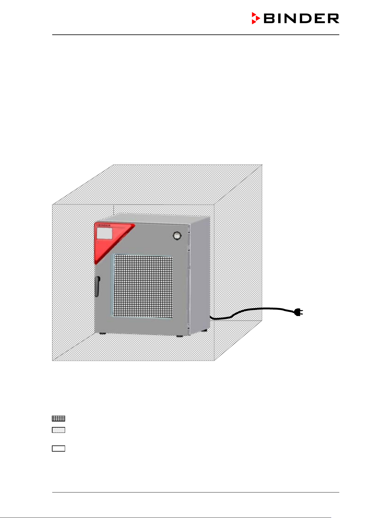
3.5.2 Area classification in the surroundings of the chamber
The VDL vacuum drying oven, with the exception of the power plug and the plug connection of the optional
analog output, is classified in category 3 in relation to the environment. It may be installed in areas in which
explosive atmospheres may occur on a rare and temporary basis.
The chamber plug (power plug) is unpr otec ted bec ause it m us t be disconnect ed in c ase of an emergency
to completely sep arate the c hamber fr om the power s upply. Therefore, the electrical c onnection m ust be
established outside a zone. With optiona l analog output: The plug connection of the analog outp ut is unprotected and must therefore be established outside a zone.
Spreading of an ex plosive atmospher e, which may occur on a rare and tem porary basis, to unprotected
areas m ust be reliably prevented by m easures of the operator. In particular, this includes a s ufficiently
dimensioned one technical ventilation according to country-specific regulations (TRBS 2152 Part 2 for Germany) and compressed air sweeping).
Figure 8: Area classification in the surroundings of the chamber
(schematic representation, standard device)
Occurrence of an explosive atmosphere:
Occasionally: in the chamber interior with tubing
On a rare and temporary basis: in the ambiance of the chamber, wi th the exception of the power plug
and the plug connection of the optional analog output
Never (unprotected areas): Connection location of the power plug and the plug connection of the
optional analog output
VDL (E3.1) 10/2020 Page 46/196
Page 47

front rear
3.5.3 Area classification in the surroundings of the chamber: extraction lead to the
pump, location of the pump
VDL
Pump module
with pump
(example)
Pump
(example)
VDL
(rear)
Occurrence of an explosive atmosphere:
VDL (E3.1) 10/2020 Page 47/196
Figure 9: Area classification in the surroundings of the chamber during operation (example)
Occasionally: interior of VDL, line to the vacuum pump, pump
On a rare and temporary basis: surroundings of VDL and pump, interior of the pump module
Page 48
4. Completeness of delivery, transportation, storage, and ins t alla-
tion
4.1 Unpacking, and checking equipment and completeness of delivery
After unpacking, p lease check the chamber and its o ptional accessories, if any, based on the delivery
receipt for completeness and for transportation damage. Infor m the carrier immediately if trans portation
damage has occurred.
The final tests of the manufacturer may have caused traces of the shelves on the inner surfaces. This has
no impact on the function and performance of the chamber.
Please remove an y transportation protection de vices and adhes ives in/on th e cham ber and on the door s
and remove the operating manuals and accessory equipment.
Due to different installat ion heights abo ve sea level, a s light negative pres sure in the inner chamber m ay
prevent the door from being opened. Therefore, after unpacking the chamber, rem ove the plug “Manual
ventilation” (7) for emergenc y ventilation from the tube to ensur e pressure equal ization. After this, thor-
oughly reinstall the plug.
CAUTION
Risk of injury due to sliding or tilting of the chamber in case of improper lifting.
Injuries, damage to the chamber.
∅ Do NOT lift the chamber using the door or the handle.
∅ Do NOT use technical equipment to lift the chambers.
Lift chambers size 23 and 56 from the pallet at the four lower corners with the aid of 4
people.
Lift chambers size 115 from the pallet with the aid of 6 people.
If you need t o return the chamber, please use the original packing and observe the guidelines for safe lifting
and transportation (chap. 4.2).
For disposal of the transport packing, see chap. 27.1.
If you ordered the optional pump modulewith a chemical membrane pum p, the pu mp will be delivered in a
separate box and must be fitted into the pump module and connected at the place of installation (see chap.
6.5.3).
Note on second-hand chambers (Ex-Demo-Units):
Second-hand cham bers are chambers that were used f or a short time for tests or exhibitions. T hey are
thoroughly tested before resale. BINDER ensures that the chamber is technically sound and will work flawlessly.
Second-hand chambers are marked with a sticker on the chamber door. Please remove the sticker before
commissioning the chamber.
VDL (E3.1) 10/2020 Page 48/196
Page 49

4.2 Guidelines for safe lifting and transportation
After operation, please observe the guidelines for temporarily decommissioning the chamber (chap. 27.2).
CAUTION
Risk of injury due to sliding or tilting of the chamber in case of improper transport
or by lifting heavy loads.
Injuries, damage to the chamber.
Transport the chamber in its original packaging only.
For moving or shipping, secure the chamber with transport straps.
∅ Do NOT lift or transport the chamber using the door or handle.
Lift chambers size 23 and 56 at the four lower corners with the aid of 4 people.
Lift chambers size 115 with the aid of 6 people.
• Permissible ambient temperature range during transport: -10 °C / 14 °F to +60 °C / 140 °F.
You can order transport packing for moving or shipping purposes from BINDER Service.
4.3 Storage
Intermediate storage of the empt y chamber is possible in a close d and dry room . Observe the guide lines
for temporary decommissioning (chap. 27.2).
• Permissible ambient temperature range during storage: -10 °C / 14 °F to +60 °C / 140 °F.
• Permissible ambient humidity: max. 70 % r.h., non-condensing
When after storage in a cold location you transfer the chamber to its warmer installation site, condensation
may form. Befor e s tart -up, wait at le as t o ne ho ur un ti l t he c hamber has attained a mbient temperature and
is completely dry.
5. Location of installati on a nd a m bie nt condi t ions
5.1 General requirements for installation
Set up the vacuum drying oven o n a flat, even and non-f lammable sur face, free f rom vibration, i n a wellventilated, dry location and align it using a spirit le vel or laser. The site of insta llation m ust be capable of
supporting the cham ber’s weight (s ee technica l data, c hap. 28.3). T he cham bers are desi gned for setting
up inside a building (indoor use). Provide active extraction (technic al venti lat ion , chap. 5.2.2).
Minimum distances
• Distance between several chambers of the same size: 250 mm / 9.8 in
• Wall distances to rear: 100 mm / 3.9 in
• Lateral wall distances: 70 mm / 2.76 in
• Spacing above and behind the chamber: 100 mm / 3.9 in.
VDL (E3.1) 10/2020 Page 49/196
Page 50

NOTICE
Danger by stacking.
Damage to the chambers.
∅ Do NOT place vacuum drying ovens on top of each other.
Permissible areas
The VDL vacuum dr ying oven may be install ed in areas in which exp losive atm ospheres ma y occur on a
rare and temporary basis. The entire chamber with the exception of the power plug is classified in category
3 in relation to the envir onment. The chamber plug (power p lug) is unprotected, therefore the el ectrical
connection mus t be established outside a zone. W ith optional analo g output: The p lug connection of the
analog output is unprotected and must therefore be established outside a zone.
VDL vacuum dr ying ovens are not intende d for installation in a Zone 1 or 0. T he chamber must not be
installed or operated in an occas ionall y or conti nuous ly / f or long p eriods / fr equentl y poten tially explos ive
area. Measures must be taken to prevent the spread of explosive atmospheres to unprotected areas.
Spreading of an ex plosive atm osphere to the unpro tected ar eas must be rel iably pre vented. O bserve the
information on zone classification (chap. 3.5).
Observe the instructions on extraction (technical ventilation, chap. 5.2.2). When installed as intended, there
is no Zone 1 or 0 in the vicinity of the chamber.
DANGER
Explosion hazard by penetration of an explosive atmosphere to unprotected areas.
Serious injury or death from burns and / or explo sion pressure.
∅ Do NOT operate the chamber in occasionally or continuously / for long periods / fre-
quently potentially explosive areas. It is not intended for installation in a zone 1 or 0.
Make sure that there are NO combustible dusts in the vicinity of the chamber
Make sure that air-solvent mixtures are NOT occasionally or continuously / for long pe-
riods / frequently in the vicinity of the chamber.
Strictly observe the relevant legal regulations about how to select an appropriate loca-
tion.
The operator is responsible for the correct installation of the pump or other equipment (zone classification).
Sufficient extraction (technical ventilation, chap. 5.2.2) also in the event of an error (e.g. damage / overfilling
the condensat e catchp ot of the pum p, or s pilling or dropp ing conta iners or m aterial to be loaded with so lvents) must be provided.
The operator is responsible to use suitable pumps for pumping from zone 0 or 1.
Follow country-specific regulations for explosion protection.
If you ordered the opt ion al pump module with chemical membrane pump, the va c uum pump will be delivered in a separate box and must be fitted into the module and connected at the place of installation (chap.
6.5.3).
Electrical connection
To completely separat e the cham ber from the power supp ly, you mus t disconnect the power plug. Install
the chamber in a wa y that the po wer p lug is e asil y acc essible and c an be e asil y pulled in case of dang er.
It is also possibl e t o us e a c ustomer’s explosion-protected emergency stop s witc h or a comparable po w er
disconnector.
The chamber plug (power plug) is unpr otec ted bec ause it m us t be disconnect ed in c ase of an emergency
to completely sep arate the cham ber from the power supply. therefore, the electrical connec tion must be
established outside a zone.
VDL (E3.1) 10/2020 Page 50/196
Page 51

DANGER
Explosion hazard due to sparking when disconnecting an improper electrical connection.
Serious injury or death from burns and / or explo sion pressure.
Make sure that the electrical connection is located outside a zone t.
Connect the plug outside the installation area of the VDL and the pump. Take into ac-
count the information on zone classification (chap. 3.5.2)
For the user there is no risk of temporary overvoltages in the sense of EN 61010-1:2010.
5.2 Ventilation and extraction (technical ventilation)
5.2.1 Ventilation for heat removal in normal operation
Install the vacuum drying oven in a well-venti lat ed plac e.
NOTICE
Danger of overheating due to lack of ventilation.
Damage to the chamber.
Do NOT set up chambers in non-ventilated recesses.
Ensure sufficient ventilation for dispersal of the heat.
Observe the prescribed minimum distances when installing the chamber (chap. 5.1)
5.2.2 Technical ventilation during chamber operation and when emptying the conden-
sate catchpot of the pump
Provide active ex trac tio n at the location of i ns tal lat ion . The extraction shall b e provided as technic al ventilation according to country-specific regulations (TRBS 2152 Part 2 for Germany). It must include the entire
installation area of the chamber.
In normal operation, it af fects in particular the loading area of the chamber for the spat ial limitation and
reduction of any possible explosive atmosphere when loading the chamber. Also in the event of a fault (e.g.
if the material to be loaded or the filled condensate catchpot of the pump falls down), it c auses spatial
limitation and reduction of any possible explosive atmosphere.
Extraction must be active d uring the entire operation of the c hamber and when handling the con densate
catchpot of the pump. Extraction must lead into an explosion-proof area.
The operator mus t ensure activ e extraction bef ore starting up the cham ber. Extraction m ust be provid ed
during the entire operation of the chamber as well as when handling the condensate catchpot of the pump.
This ensures that solvent vapors never reach unprotected areas or accumulate in an impermissible manner.
If the technical ven tilation fails, the power to th e vacuum drying oven must be s witched off. It must be
ensured that the dev ice ca n be s witch ed off by the oper ator us ing an expl osion-protected device: Pull o ut
the power plug or operate e.g., a customer’s explosion-protected emergency stop switch.
5.2.3 Air supply (breaking the vacuum) during operation with inert gas
When operating the VDL safety vacuum drying oven with inert gas, correctly follow the technical ventilation
measures, as desc ribed in the DGUV guidelines 213-850 on safe work ing in laboratories, issued by the
employers’ liability insurance association (for Germany).
VDL (E3.1) 10/2020 Page 51/196
Page 52
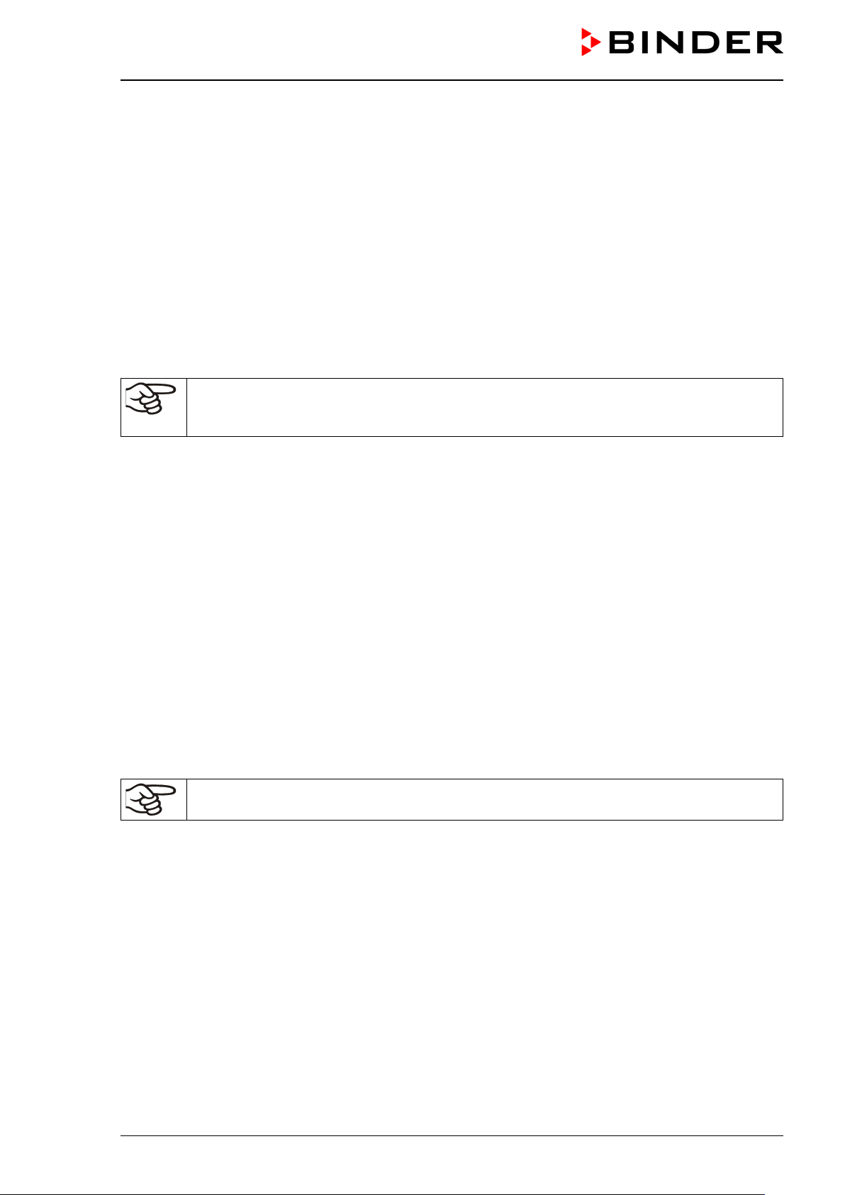
5.3 Equipotential bonding
The accessible installat io n and o per at in g s urface of the chamber mus t be elec trically conductive. The accessible installation and operating surface of the chamber must be electrically conductive. This installation
and operating surface m ust be connected to the vacuum dr ying oven and other equipment (e.g. Pum p
module, vacuum pump) according to the grounding concept. Provide cyclic measurements.
For the grounding concept see chap. 6.8.
When inserting or loa ding objects into th e loading area , note t hat there may be a potential equali zation.
The personal protective equipment (PPE) of the operating personnel must be implemented ESD protected.
5.4 Ambient conditions
• Permissible ambient temperature during operation: +18 °C / 64 °F to +32 °C / 90 °F.
The ambient temperature should not be substantially higher than the indicated ambient temperature of +22 °C +/- 3 °C / 71.6 °F +/-5.4 °F to which the specified technical data relate. Deviations from the indicated data are possible for other ambient conditions.
• Permissible ambient humidity: 70 % r.h. max., non-condensing.
• Installation height: max. 2000 m / 6562 ft above sea level.
The maximum permissible ambient temperature of the vacuum pumps delivered by BINDER is 40 °C / 104
°F.
5.5 Compr essed air supply for sweeping the area for electrical equipment, the
preheating chamber, and the controller housing
Before commissioning the chamber, connect the vacuum drying oven to the compressed air supply (chap.
6.3).
The compressed air s upply line provided by the operator m ust be equipped with ac tive monitoring of the
defined inlet pressur e (2 bar), which clearl y indic ates a dr op a nd inc reas e in t he in let pr es s ur e outsi de t he
permissible tolerance of ± 0.2 bar.
5.6 Fire extinguisher
During operation a fire extinguisher must be available.
5.7 Lightning protection device
The building in which th e vacuum drying oven is installed m ust have a lightning protection system . All
internal connections in the operator's building must contain lightning protection in accordance with EN/IEC
62305-3.
Lightning protectio n measures must be tak en i n order t o pr e ve nt melting and spraying ef f ec ts . The operator’s zone classification shall be used to plan lightning protection measures. The lightning discharge paths
must be designed so that heat or ignitable / spray sparks cannot become the ignition source for an explosive
atmosphere.
VDL (E3.1) 10/2020 Page 52/196
Page 53

The vacuum expansion racks made of aluminum (also option-
6. Installation and connections
The chambers m ay only be installed, connected, a nd commissioned by speciali st personnel. Specialist
personnel must have knowledge of the t ypes of ignition protection and regulations and ordinances for
equipment used in hazardous areas (Ex areas).
Verify whether the Ex classification (Ex classification label on the type plate) is suitable for the application.
6.1 Vacuum expansion racks and rack holders
Vacuum expansion r acks and rack holders can easily be removed from the chamber. This of fers the
advantage of an inner chamber with smooth walls, which is easy to clean.
Inserting or loosening an expansion rack and inserting or removing the rack holders may only be
done in the absence of solvents and under extraction (technical ventilation).
The rack holders can only be removed from the chamber after removing the expansion racks.
Rack holder installat ion: Align th e rack holders to the c ams in the bottom of the in ner cham ber and inser t
them.
Prior to insertion c heck the expa nsion racks and rack holders for corrosion . If corrosion is detec ted, the
affected element must not be used.
Explosion hazard due to creation of mechanical sparks in an explosive atmosphere.
Serious injury or death from burns and / or explo sion pressure.
Insert or remove the expansion racks and rack holders only in the absence of solvent.
Insert or remove the expansion racks and rack holders only with active extraction
(technical ventilation).
Prior to inserting the expansion racks and rack holders, check them for corrosion.
∅ Do NOT use corroded expansion racks and rack holders.
ally available in stainless steel) allow low-loss heat transfer to
the material. The str ong te n s ion caus es t he r acks to fit tightly
against the interi or wall and their l arge-surface conta ct area
ensures rapid and effective heat transfer.
The removable rack holders allow for easy positioning.
You can remove the expansion racks for easy cleaning. Do
not remove them too often in order to prevent wear.
DANGER
Figure 10: Operating the expansion racks
• Pushing the locking lever: The expansion rack is released and can be removed.
• Pulling the locking lever: The expansion rack is pressed against the inner chamber walls.
Remove or insert the vacuum expansion racks only when the chamber is empty and has
cooled down. NO explosive atmosphere must be present. Active extraction (technical ventilation) is mandatory.
VDL (E3.1) 10/2020 Page 53/196
Page 54

(a)
(b)
(d)
(c)
(e)
(f)
(g)
(h)
(i)
(i)
Following each new tightening of an expansion rack, check that the lateral parts of the rack fit
closely over their whole surface to the inner chamber wall. This is necessary in order to ensure the specified temperature exactitude.
NOTICE
Risk of invalid calibration due to modified heat transmission when changing between aluminum and stainless-steel racks.
Undefined heating behavior.
∅ Do NOT change between aluminum and stainless-steel racks
∅ Use the supplied expansion racks only.
6.2 Mounting the pressure regulator
The pressure regulator is included with the chamber and must be mounted on the chamber rear
Accessory pack for mounting the pressure reg ulator
(a) pressure regulator
(b) tube
(c) 6 screws
(d) brass nozzle for compressed air connection
(e) bracket
(f) cable connector
(g) 2 nuts
for the bolts with thread on the chamber rear
Connections on the chamber rear as supplied
(h) hole for the cable connection
(i) 2 bolts with thread
VDL (E3.1) 10/2020 Page 54/196
Page 55

(f)
(c)
(c)
(c)
(c)
(c)
(c)
(e)
(b)
(f)
(c)
(e)
(d)
(b)
(a)
(g)
Figure 11: Mounting the pressure regulator on the chamber rear
Proceed in the following order:
• Insert the cab le connec tor (f ) into the exis ting ho le (h)
in the rear wall until it clicks into place
• Unscrew the thr e e screws (c) pointing to the cham ber
from the pressure regulator
• Fix th e t hr ee s cr ews (c) together with the bracket l (e)
on the pressure regulator
VDL (E3.1) 10/2020 Page 55/196
Page 56

Use only dry compressed air.
(f)
(g)
Fixation on the chamber rear:
• Guide the tube (b) through the cable connector (f) and
push the bracket (e) with t he pressure regulator with
its lower two holes onto t he two bolts (i) on the rear of
the chamber
• Screw the two nu ts (g) onto the bolts (i) and tighten
them
• Tighten the nut of the cable connector (f) which points
to the chamber c lock wise w ith a tool s o that it can no
longer be loosened by hand
6.3 Connecting compressed air supply for sweeping the area for electrical equipment, the preheating chamber, and the controller housing
The compressed air flows through the area for electrical equipment, the preheating chamber, and the controller housing, which prevents a possible concentration of a solvent-containing atmosphere in the presence
of live electrical components and the hot heater surface.
In order to avoid that any oil coming from the compressed-air piping
enters the vacuum drying oven, the compressor of the compressed
air system must be equipped with an oil separator, or the compressed air system must be constructed oil-free.
Connection:
Before commissioning, the pressure regulator on the chamber rear
must be connected to a compress ed air line (compr essed air network).
Connection: Plug connector for DL quick coupling NW5
An inlet pressure of 2 bar must be provided for the compressed air
sweeping. The compressed air supply line provided by the operator
must be equipped w ith monitoring which clearl y indicates a drop
and increase in the inlet pressure outside the permissible tolerance
of ± 0.2 bar.
Figure 12: Compressed air connec-
tion on the pressure regulator
If solvent-containin g air penetrates the electrical area s of the cham ber or the preheat ing cham ber, exp losions may result.
VDL (E3.1) 10/2020 Page 56/196
Page 57

Figure 13: VDL mounted on pump module
(example size 115)
Figure 14: Pump module, rear view
(15)
(14)
DANGER
Explosion hazard by solvent-containing air penetrating the electrical area of the
chamber or the preheating chamber.
Serious injury or death from burns and / or explo sion pressure.
∅ Make sure that the air for the compressed air supply is NOT taken from explosive at-
mospheres.
∅ Ensure that the compressed air supply line provided by the operator is equipped with
active monitoring of the defined inlet pressure.
Do NOT start the VDL vacuum drying oven when the chamber is not connected to the compressed air supply, or if the specified overpressure is not reached.
6.4 Pump module (option)
The mounting instructions Art. no. 7001-0137 supplied with the pump moduledescribe
how to mount the vacuum drying oven onto the pump module and installing the suction
line into the pump module.
(14) Connection to extraction
(15) Fixation screw fitting for grounding
VDL (E3.1) 10/2020 Page 57/196
(example size 115)
Page 58
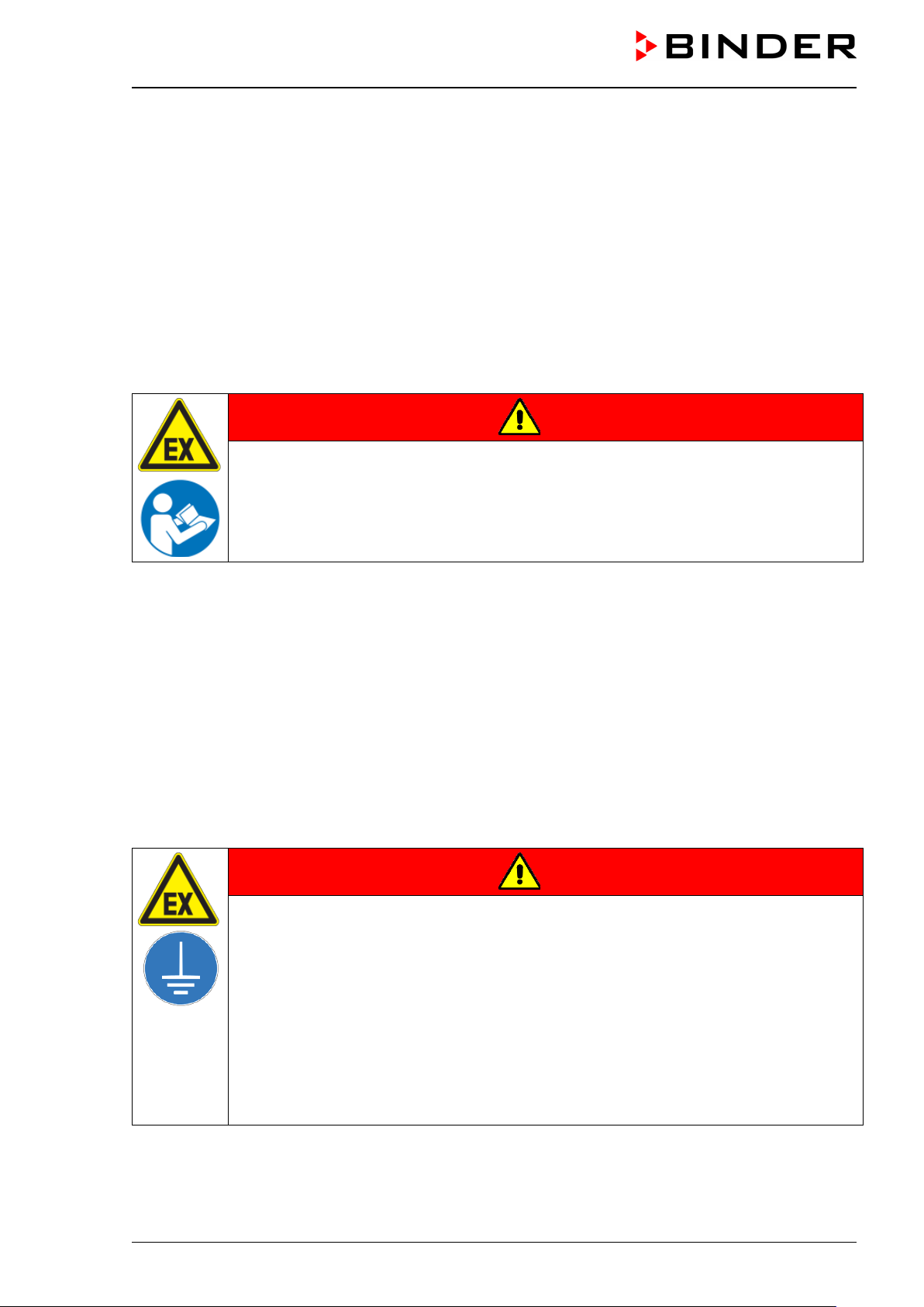
The following steps 6.4.1 to 6.4.3 are described in detail in the mounting instructions Art . no. 7001-0137.
Please proceed accordingly.
6.4.1 Mounting
• Placing the vacuum drying oven on the vacuum module
• Mounting the connecting plate
• Installing the s uction line: Hos e connection at th e VDL vacuum connection (11) and fixing the hose at
the housing rear
• Installing the condensate collecting tray
Inappropriate execution of the connections can lead to the risk of explosion.
DANGER
Danger of ignition and explosion by inappropriate installation.
Serious injury or death from burns and / or explo sion pressure.
It is obligatory to follow the instructions of the mounting instructions Art. no. 7001-0137
regarding correct installation.
Observe the safety advice as in chap. 1.7.3.
6.4.2 Achieving equipotential bonding acc. to the grounding plan
• The conducti ve connection between the VDL and the pum p module is established by mounting the
connecting plate.
• To establish a conductive connection b etween the vacuum pum p and the pump module a gro unding
cable is supplied, which is already fixed at the pump module. It will be connected to the pump.
• To establish a conductive connection between the condensate collecting tray and the pump module the
front edge of the tray is screwed on the front of the vacuum module
• To establis h a conductive connection between th e pump module and the conductive s urface of the
installation site a grounding cable is supplied with the pump module. It is screwed on the fixation screw
fitting for grounding of the pump module and connected to the conductive surface of the installation site.
DANGER
Explosion hazard due to electric sparking due to missing or improperly implemented equipotential bonding.
Serious injury or death from burns and / or explo sion pressure.
Connect all elements in the installation and loading area (VDL / pump module / pump)
with the conductive surface and/or with each other. Proceed according to the grounding
plan in chap. 6.8.
For installation of the pump module proceed acc. to the mounting instructions of the
pump module (Art. no. 7001-0137).
Before commissioning, measure the equipotential bonding after first setting up the VDL
and implementing all described measures for establishing the equipotential bonding
Provide cyclic measurements of the equipotential bonding.
VDL (E3.1) 10/2020 Page 58/196
Page 59

6.4.3 Connection of an extraction system at the pump module
Avoid the solvent accumulation in the pump module as this would cause the pump module to
become an occasionally or continuously / for long periods / frequently potentially explosive
area (Zone 0 or 1). The VDL vacuum drying oven located on top of the module is constructed
in device category 3 in regards to its surroundings.
DANGER
Explosion hazard due to the spread of an explosive atmosphere to unprotected
chamber parts and ignition due to electric sparking or hot surfaces
Serious injury or death from burns and / or explo sion pressure.
Provide active extraction (technical ventilation according to country-specific regulations
– TRBS 2152 Part 2 for Germany) prior to commissioning the chamber.
Extraction must include the entire installation area of the vacuum drying oven and pump
module.
Connect an extraction system to the provided port on the rear of the pump module.
6.5 Vacuum connection
Connect the vacuum drying oven to a vacuum pumpor to a domestic vacuum system. For this purpose, the
vacuum connection (6) with sm all flange DN16 m ust be connected to the back of the cham ber at the top
with the vacuum pump or domestic vacuum system via a vacuum suction hose or a fixed vacuum pipe.
(6)
Figure 15: Position of the Vacuum connection (6) on the chamber rear (example size 56)
When using a vacuum suction hose BINDER recommends the connection kit for the VP4 pump from
BINDER (chap. 6.5.5). The optional pump module (chap.) provides an appropriate hose port on the rear.
6.5.1 Instructions for using vacuum pumps
Vacuum pumps with a suction capacity of 1-30 m³/h are suitable for the VDL vacuum drying
oven.
For use of vacuum pumps in the European Union, note the following points:
• Units that will be operated in pote ntially explosive are as have to meet the re quirements of ATEX Di-
rective 2014/34/EU. Observe the safety instructions in chap. 1.7.
VDL (E3.1) 10/2020 Page 59/196
Page 60

• If combustible solvent will be introduced into the inner chamber, the vacuum pump must be constructed
in a suitable exp losi on-proof manner. The m ixt ures ex trac ted f r om the drying chamber m us t be c arr ie d
away making sure that there is no danger by ignition of these atmospheres.
Follow the safety instructions of the pump manufacturer.
In the event of an error, sparking in the pump motor or the switching elements, electrostatic discharges, as
well as hot pump parts can ignite solvent vapors. Minimize this risk by using an ATEX Directive 2014/34/EU
compliant vacuum pump suitable for suction f rom Zone 0 or 1 and, if appr opriate, from the zone of its
installation site.
DANGER
Explosion hazard caused by emerging solvent vapors, which can ignite due to
sparking in the pump motor or the switching elements, electrostatic discharges and
hot pump parts.
Serious injury or death from burns and / or explo sion pressure.
Use only suitable, explosion-proof pumps
Operate the pump in a stationary position and secure it so it is immobile.
Make sure that the suction line to the vacuum connection (6) is installed fix and conduc-
tive.
Avoid that the exhaust pipe conducts ignitable solvent concentrations by sufficient sol-
vent condensation e.g., in an exhaust waste vapor condenser
Make sure that the exhaust pipe is installed fix and conductive in case it may still con-
duct ignitable solvent concentrations.
Ensure equipotential bonding between the pump housing and the housing of the VDL
vacuum drying oven via the connected equipment grounding conductors of both units.
When using ATEX Directive 2014/34/EU non-compliant pumps:
Provide a current-dependent, delayed protective device for the pump (for the triggering
time of this protective device, see the manufacturer’s specifications). The protective and
monitoring device must not be able to independently turn on again or be released.
Install the switch gear box outside the hazardous area or provide it with explosion pro-
tection.
The ATEX Directive 2014/34/EU compliant pumps offered by BINDER provide an integral
protective device and an integral explosion proof switch.
Make sure that the vacuum source is designed for a gas inlet temperature corresponding to
the used drying temperature, or take appropriate measures to cool down the extracted vapor
before it enters into the vacuum source.
Observe the permissible gas inlet temperature of the vacuum pump in use. Do NOT exc eed this
temperature. If the gas inlet temperature is too high and then becomes even warmer by compression in the
pump, the resulting t emperature (of the gas-solvent m ixture inside t he pump) could ex ceed the solv ent’s
temperature class and auto-ignition temperature .
VDL (E3.1) 10/2020 Page 60/196
Page 61

Cooling water outlet (hose nozzle 6 mm)
Guard plate
DANGER
Fire and explosion hazard by exceeding the auto-ignition temperature of the solvent
with a too high gas inlet temperature.
Damage to the vacuum pump. Serious injury or death from burns and / or explosion
pressure.
Do NOT exceed the maximum gas inlet temperature of the pump. Adjust the tempera-
ture set-point accordingly.
With a higher set-point temperature, take appropriate measures to cool down the ex-
tracted vapor before it enters into the vacuum pump.
Extracted vapors can have a health damaging and/or corrosive effect on the chamber and pump.
CAUTION
Health hazard due to release of extracted vapors.
Corrosion of oven and pump. Damage to health.
Conduct the extracted vapors e.g., into a fume extractor facility. Connect a suitable
hose to the vacuum pump outlet that may be located in the pump module.
To avoid condensation inside the chamber and in the suction system, select an appropriate vacuum source
to ensure its sufficient performance in relation to the released amount of steam. Coordinate drying temperature, suction performance of the vacuum source and the amount of loading material.
6.5.2 Vacuum pump VP4 (option)
. The VP4 chemical m embrane p um p is located in a separ ate tr anspor t pack aging. It is delivered as complete pump stand with a separator and an exhaust waste vapor condenser.
We recommend to install the vacuum pum p in the optional pump m odule. For installation of the pump,
please refer to chap. 6.5.3.
Outlet port (gas!)
Exhaust waste vapor
condenser
Cooling water inlet (hose
nozzle 6 mm / 0.23 in)
Carrying handle
Inlet (vacuum connection)
Round bottom flask as con-
VDL (E3.1) 10/2020 Page 61/196
densate catchpot
Figure 16: Vacuum pump VP 4 (MZ2C EX)
Page 62

Defining the zone of the installation site of the vacuum pump (Directive 1999/92/EC)
If the pump module is defined as Zone 1, the operating cham ber of the vacuum pump must be swept with
inert gas. A flow of at least 1 liter per minute (without pressure) is needed. For Zone 2 or without any zone
sweeping with inert gas is not required. In addition to sweeping with inert gas, in case of condensing media,
you can connect a gas ballast in order to avoid condensation.
The ATEX Directive 2014/34/EU compliant vacuum pump offered by BINDER is designed for a gas
inlet temperature of 40 °C / 104 °F max. Do NOT exceed this temperature. If the gas inlet temperature is
too high and then becomes even warmer by compress ion in the pump, the resul ting temperature (of the
gas-solvent mixture ins ide the pum p) c ould exceed th e s olvent’s tem per ature clas s and auto-ignition temperature.
DANGER
Fire and explosion hazard due to exceeding the solvent’s auto-ignition temperature
by exceeding the gas inlet temperature.
Damage to the vacuum pump. Serious injury or death from burns and / or explosion
pressure.
Do NOT exceed the set-point temperature 40 °C / 104 °F.
With a set-point temperature above 40 °C / 104 °F, take appropriate measures to cool
down the sucked-in gas before its entry to the vacuum pump.
The maximum perm issible ambient temperature of the v acuum pumps supplied by BINDER is 40 °C /
104 °F.
6.5.3 Installation of the vacuum pump VP4 in the pump module (option)
Avoid the solvent accumulation in the pump module as this would cause the pump module to
become an occasionally or continuously / for long periods / frequently potentially explosive
area (Zone 0 or 1). The VDL vacuum drying oven located on top of the module is constructed
in device category 3 in regards to its surroundings.
Installation of the supplied vacuum pump
• The vacuum drying o ven is m ounted onto the pump m odule as descr ibed in the m ounting instructions
Art. No. 7001-0137.
• The suction line to the pump module is installed as described in the mounting instructions Art. No. 7001-
0137. Connect the vacuum connection (6) (small flange DN 16) on the back of the chamber to a vacuum
suction lead. When using a vacuum tube BINDER recommends the BIN DER connection kit for VP4
(chap. 6.5.5). The optional pump module has a corresponding hose outlet on its rear.
• When the pump is removed from the original packaging, place it in the pump module.
• Connect the grounding elements as described in the mounting instructions Art. no. 7001-0137.
• Connect the pre-installed suction line to the vacuum pump inlet at the suction-side small flange connec-
tion located at the top of the condensate catchpot).
• Connect a co nduit that is s uitable for rem oving the extrac ted vapors from the pump m odule, onto the
pressure-side connection of the vacuum pump (hose olive on the top-back of the emission condenser).
• Guide the end of the conduit into an exhaust air system, which is explosion-proof constructed in consideration of any possible res idua l solvent c onten ts. T he operator m ust check if an ex plosive atm os phere
may be present at the p ump exit or at the exhaust w aste vapor condenser. For this p urpose, use a
calculation of the solvent’s partial pressure at the set-up coolant temperature of the exhaust waste vapor
condenser and com pare it to the exp losion lim its of the pum ped solve nt. The exha ust solvent c oncentration should be minimized by selecting the most appropriate condensation temperature for the solvent
at the refrigeration plant that can be connected to the exhaust waste vapor condenser.
VDL (E3.1) 10/2020 Page 62/196
Page 63
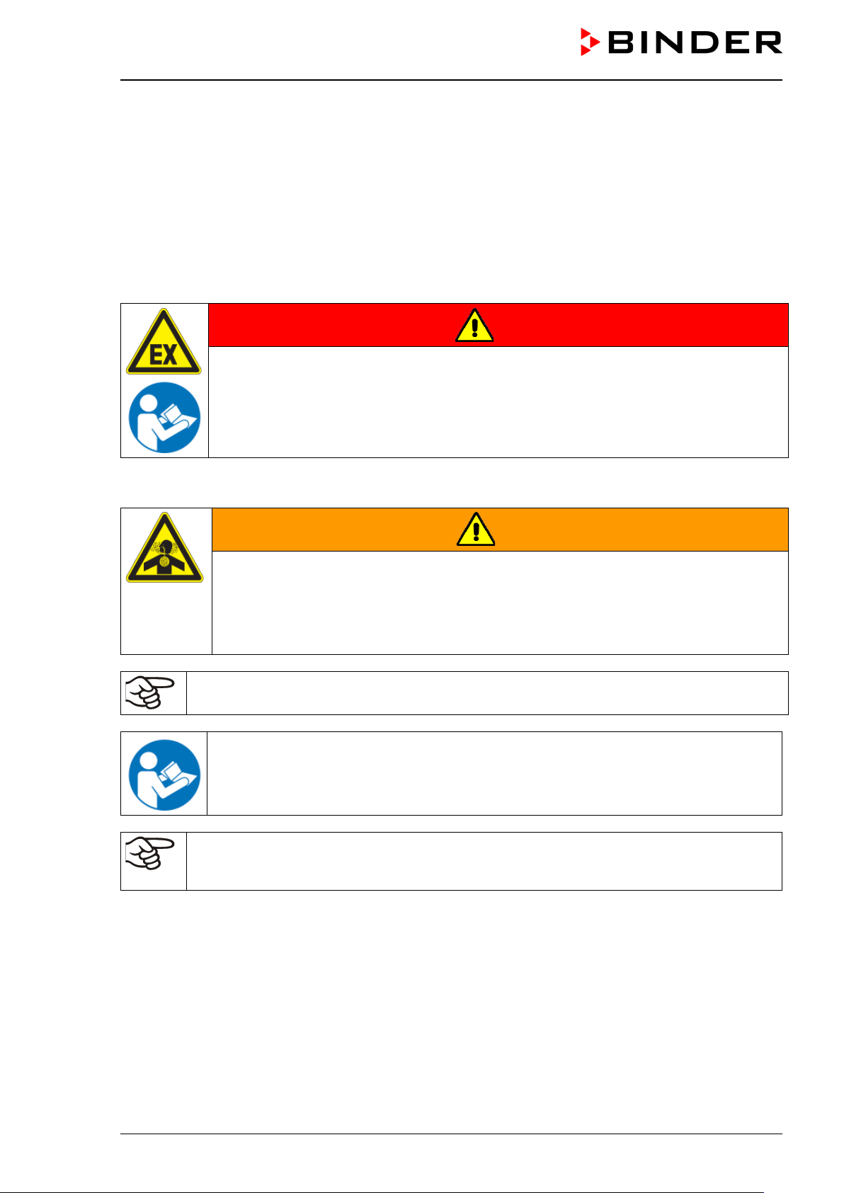
The pumped-out gases at the pump exit or the ex haus t waste vapor c ondenser m ust be rem oved in a
controlled manner and ac cording to applicable secur ity regulations. If there is any pos sibility that an
explosive mixture could still exist, the exhaust must be removed through antistatic conduits and disposed
of according to the valid regulations of explosion protection.
• Establish th e elec tric al con nectio n at the p um p’s c onnect or box . This m ust be c arr ied out accor ding to
the original user manual of the pum p manufacturer and t o EN 60079-0, obser ving the zone that has
been defined b y the operator for the i nstallation site o f the pump. Equip otential bonding between the
pump housing and the housing of the vacuum drying oven must be assured by the connected equipment
grounding conductors of both units.
Inappropriate execution of the pump connection can lead to the risk of explosion.
DANGER
Danger of ignition and explosion by inappropriate pump connection .
Serious injury or death from burns and / or explo sion pressure.
It is obligatory to follow the instructions of the pump manufacturer regarding correct
connection and commissioning.
Observe the safety advice as in chap. 1.7.
Extracted vapors or the oc casionally used inert gas can endanger healt h and / or have a corros ive effect
on the oven and pump.
WARNING
Danger of damage to health by release of extrac ted vapors.
Corrosion on the chamber and the pump. Damag e to he alth.
Remove the extracted vapors and/or inert gas via a suitable conduit from the pump
module into e.g., a fume extractor facility.
Directly connect the conduit to the corresponding pump outlets.
You can connect a laboratory cooling system to the emission condenser of the vacuum pump
VP4.
To operate the chemical membrane pumps VP4 (MZ2C EX) please refer to the enclosed
pump manufacturer's operating manual.
Confirm that the vacuum source is designed for a gas inlet temperature corresponding to the
used drying temperature, or take appropriate measures to cool down the extracted vapor before its entry into the vacuum source.
The ATEX Directive 2014/34/EU compliant vacuum pump offered by BINDER is designed for a gas
inlet temperature of 40 °C / 104 °F max. Do NOT exceed this temperature. If the gas inlet temperature is
too high and then becomes even warmer by compress ion in the pump, the resul ting temperature (of the
gas-solvent mixture ins ide the pum p) c ould exceed th e s olvent’s tem per ature clas s and auto-ignition temperature .
The maximum permissible ambient temperature of the vacuum pump supplied by BINDER is 40 °C / 104 °F.
VDL (E3.1) 10/2020 Page 63/196
Page 64

6.5.4 Note on the use of a flame arrester
A flame arrester is not mandatory for VDL applications (TRBS 2152-4:2012). A pump designed for Zone 1
is equipped with a t emperature sens or on the bear ing which, in th e event of a f ault, causes the pump to
shut down immediately.
In general: In case of a risk of ignition before or after the vacuum pump, the operator must provide suitable
flame arresters in accordance with EN 12874. The suitability (chemical resistance, sufficient flow and safety
against clogging) must be ensured before commissioning.
6.5.5 ATEX connection kit for vacuum pump VP4 (option)
Connection kit for VP4 (Art. no. 8012-0621) consists of:
• Straining ring DN10/16 (3 pc.)
• Universal centering ring DN10/16 (3 pc.)
• Transition piece, adapter DN 16-10/8 (2 pc.)
• Vacuum hose 10/8, 2 m / 78.7 in
• Union nut M14 (2 pc.)
• Elbow DN 10/10
For mounting the VDL connection kit for VP4, please refer to the mounting instructions Art.
no. 7001-0152 supplied with the connection kit.
6.6 Connecting inert gas supply
When operating the VDL vacuum drying oven with inert gas, correctly follow the technical ventilation
measures, as desc ribed in the DGUV guidelines 213-850 on safe work ing in laboratories, issued by the
employers’ liability insurance association (for Germany
When operating with inert gas, the chamber is supplied with an oxygen displacing gas, e.g., N
in high concentrations are hazardous to health. They are colorless and almost odorless and therefore practically imperceptible. I nhalation of inert gases can c ause drowsiness up to respira tory arrest. When the O
content of the air decreases below 18%, t here is risk of death f rom lack of oxygen. An y gas that might
escape has to be led out via good room ventilation or a suitable exhaust system.
. Inert gases
2
2
DANGER
Risk of suffocation by inert gas in a high concentration.
Death by suffocation.
∅ Do NOT set up chambers in non-ventilated recesses.
Ensure that technical ventilation measures are activated.
Respect the relevant regulations for handling inert gases.
When decommissioning the vacuum drying oven, turn off the inert gas supply.
Connect the inert gas supp l y to th e inert g as c onnect io n (adapter with hose olive d iam et er 8 mm / 0.31 in)
via a pressure reducer. Screw the enclosed adapter with hose olive on the thread (4) at the chamber rear.
Set the pressure reduc er to a pr es sur e s lightly above ambient pressure. Ens ur e t h at the pressure reducer
will certainly open. Do not alter this setting in order to avoid perturbation inside the oven and release of big
quantities of inert gas after flooding the VDL.
VDL (E3.1) 10/2020 Page 64/196
Page 65

NOTICE
Overpressure in the inner chamber.
Perturbation of the load.
∅ DO NOT change the setting of the atmospheric pressure.
6.7 Mounting the tilt protection holders
For chambers placed on the optional pump module it is recommended to install the supplied tilt protection.
Scope of delivery of tilt protection kit (Art.no. 8009-0870):
• 2 screws
• 2 tilt protection holders
Preparing the tilt protection holder s
• Depending on the desired wall distance, you can bend the tilt protection holders accordingly.
Figure 17: Variable length of the tilt protection holder depending on the bend
Installation on the chamber
• Plug the two t ilt protection holders each with the tab into t he mounting holes and push them upward
over the rear panel. The screw holes in the rear wall and in the tilt protection holders must align.
• Fix the tilt protection holders each with one of the supplied screws on the chamber rear wall.
Wall mounting
• Then fix both tilt protection holders on the wall, each with 2 screws Ø 6mm suitable for the wall (B)
VDL (E3.1) 10/2020 Page 65/196
Page 66

VDL
6.8 Achieving equipotential bonding / Grounding concept
For systems in potentially explosive areas, equipotential bonding acc. to IEC 60079-14 is required. All electrically conductive par ts must be connected to the equipotential bo nd ing system. Connectio ns to th e equipotential bonding system must be secured against automatic loosening.
Grounding, i.e. achieving equipotential bonding is required as solvent vapors may be present during loading
and / or unloadin g. Als o when r em oving the fil led condensate catchpot f rom the p um p solvents m ay accidentally be spilled. T herefor e, the acces sible s urf ace of the installation and loadi ng area mus t be conductive, there mus t be techn ical venti lation, and all e quipm ent (VDL / pum p module / vacuum pum pmust be
connected to the conduct ive surface or to each other accor ding to the grounding concept. The personal
protective equipment (PPE) of the operating personnel must be implemented ESD protected.
VDL
M
S
P
S
Installation without pump module Installation with pump module
Figure 18: Possibilities of grounding (schematic representation)
VDL Vacuum drying oven
M Pump module
S Walkable installation and operating surface with conductive surface
P Vacuum pump
A Equipoten tial bonding between the VDL a nd the conduc tive surface of the installation an d loading
area via grounding cable
B Equipotential bonding between the VDL and the pump module via connecting plate
C Equipotential bonding between the vacuum pump and the pump module via grounding cable
D Equipoten tial b ondin g bet ween the p um p m odule and the conductive sur face of the installation and
loading area via grounding cable
E Equipotential bonding between the condensate collecting tray and the pump module via screws
VDL (E3.1) 10/2020 Page 66/196
Page 67
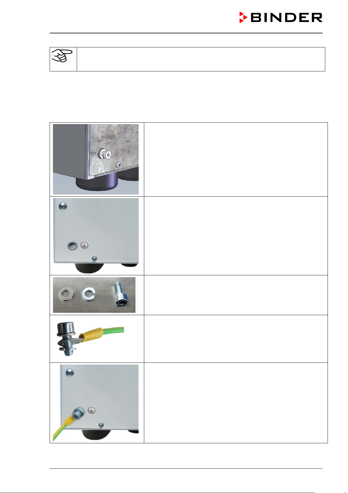
How to achieve equipotential bonding when installing the VDL with a pump module is described in detail in the mounting instructions for the pump module (Art. No. 7001-0137) supplied with the pump module.
Achieving equipotential bonding on the VDL
Equipotential bonding m ust alwa ys be m ade via external ground ing connec tions, so that no pote ntial c an
be introduced in the event of a shor t circuit. Following the installation of the VDL and having imple-
mented all the measures described to achieve equipotential bonding, we recommend performing a
protective conductor measurement before commissioning.
The VDL provides a threaded bushing for grounding on the bottom
left of the rear panel. In state of delivery the screw together with the
washer and spring washer is screwed on the threaded bushing.
Unscrew the screw.
Threaded bushing after unscrewing
Washer, spring washer, screw
Put the washer, the ring cable lug of the grounding cable and the
spring washer in this order onto the screw.
OR
Put the spring washer, the ring cable lug of the grounding cable, and
the washer directly onto the housing (recommended because this
creates minimum resistance)
Screw on the screw into threaded bushing.
Connected grounding cable
Figure 19: Mounting the groundin g cab le on the VDL
VDL (E3.1) 10/2020 Page 67/196
Page 68
DANGER
Explosion hazard by electric sparking due to missing or improperly implemented
equipotential bonding.
Serious injury or death from burns and / or explo sion pressure.
Connect all elements in the installation and loading area (VDL / pump module / pump)
with the conductive surface and/or with each other. Proceed according to the grounding
plan in chap. 6.8.
For installation of the pump module proceed acc. to the mounting instructions of the
pump module (Art. no. 7001-0137).
Make sure that the personal protective equipment (PPE) of the operating personnel is
implemented ESD protected. This applies also to gloves.
Before commissioning, measure the equipotential bonding after first setting up the VDL
and implementing all described measures for establishing the equipotential bonding.
Provide cyclic measurements of the equipotential bonding.
Always wear ESD-protected safety clothing when operating the chamber.
6.9 Electrical connection
The chambers are suppl ied ready for connection. T hey come with a fixed power connection cable of at
least 2000 mm / 78.74 in in length and a shockproof plug.
Model
VDL 23
VDL 56 Grounded plug
VDL 115 Grounded plug
VDL 23-UL
VDL 56-UL
VDL 115-UL
• The dom estic socket must also provide a prot ective conductor. Make s ure that the connection of the
protective conductor of the domestic installations to the chamber’s protective conductor meets the latest
technology. The protective conductors of the socket and plug must be compatible!
Power plug of the
power cable
Grounded plug
NEMA 5-15P 100-120 V at 60 Hz 1N~ 10 A
NEMA 5-20P 100-120 V at 60 Hz 1N~ 2 x 16 A
NEMA 5-20P 100-120 V at 60 Hz 1N~ 2 x 20 A
Nominal voltage ± 10% at the
indicated power frequency
230 V at 50 Hz
230 V at 60 Hz
230 V at 50 Hz
230 V at 60 Hz
230 V at 50 Hz
230 V at 60 Hz
Current
type
1N~ 2 x 6,3 A
1N~ 2 x 8 A
1N~ 2 x 10 A
Chamber
fuse
DANGER
Electrical hazard due to lack of a protective conductor.
Deadly electric shock.
Make sure that the power plug and power socket match and that the protective
electrical conductors of the chamber and domestic installation are securely connected.
• Prior to con nection and s tar t-up, chec k the po wer su ppl y voltag e. Compare the values to the s pecified
data located on the chamber’s type plate (left chamber side, bottom right-hand, see chap. 1.6).
VDL (E3.1) 10/2020 Page 68/196
Page 69

NOTICE
Danger of incorrect power supply voltage due to improper connection.
Damage to the equipment.
Check the power supply voltage before connection and start-up.
Compare the power supply voltage with the data indicated on the type plate.
• When connect ing, please o bserve the regul ations spec ified by the local e lectricity s upply com pany as
well as the VDE directives (for Germany). We recommend the use of a residual current circuit breaker.
DANGER
Electrical hazard due to shock after damage to the device due to pulling on the
electrical connection cable during transport.
Damage to the equipment. Deadly electric shock.
After transport, check the electrical power cable at the installation site to make
sure that it is connected correctly and securely.
∅ Do NOT operate the chamber if the power cable is damaged.
• Pollution degree (acc. to IEC 61010-1): 2
• Over-voltage category (acc. to IEC 61010-1): II
See also electrical data (chap. 28.3).
To completely separat e the cham ber from the power supp ly, you mus t disconnect t he power plug. Install
the chamber in a wa y that the po wer p lug is easil y acc essible and c an be e asil y pulled in c ase of dang er.
A customer's emergency stop switch or a comparable power disconnector can also be used.
The chamber plug (power plug) is unpr otec ted bec ause it m us t be disconnect ed in c ase of an emergency
to completely sep arate the c hamber fr om the power s upply. Therefore, t he electrical connection m ust be
established outside a zone.
DANGER
Explosion hazard due to sparking when disconnecting an electrical connection.
Serious injury or death from burns and / or explo sion pressure.
Make sure that the electrical connection is located outside a zone.
Connect the plug outside the installation area of the VDL and the pump. Take into ac-
count the information on zone classification (chap. 3.5.2)
VDL (E3.1) 10/2020 Page 69/196
Page 70

7. Explosion safety tests before commissioning
This chapter pro vides instr uctions for the user to ensure the safety of th e system and to m eet applicab le
regulations. Proper operation is only ensured after the test has been carried out and any necessary
measures implemented.
Follow the provisions on testing explosion protection according to country-specific regulations (for Germany
in particular TRBS 1201 Part 1; this substantiates th e requirements of the Industrial Saf ety Regulation
(BetrSichV) 2015) within the scope of its application.
7.1 Scope of the functional test
The test represents the e ntirety of all work equipm ent relevant to exp losion protection. This includes the
vacuum drying oven with all safety, control, and regulation devices, related work equipment such as pumps
or other vacuum systems, pump module, extraction devices, and ventilation systems, gas warning devices,
inerting devices incl uding connection elem ents as well as the installation ar ea with effective devices for
equipotential bonding and any other building components that may be relevant to explosion protection (nonexhaustive list).
• Before comm issioning a nd after changes re quiring r eview, p erform a comprehens ive inspect ion of the
system in its entirety.
• Systems must be checked in their entirety at least every 6 years.
• Tests can also be c arried out by an approved monitoring bod y or by personnel qualified for testing.
Observe relevant regulations for the qualification requirement.
• Devices, pro tec ti ve s ystems, safety, control an d r eg ulat ing d ev ic es ac c ording to Directive 20 14/3 4/ EU,
connection devices, and interactions with other parts of the system must continue to be checked at least
every three years. Tests of ventilation systems, gas warning and inerting devices must be performed at
least once per year in the future.
• It may be possible to skip recurring tests, e.g. of devices, protective systems, etc., as well as ventilation
systems, gas warning and inerting devices, if a maintenance plan is provided. The full inspection of the
entire system remains unaffected.
7.2 Explosion protection plan
The explosion prot ection plan to be crea ted by the operator re presents the entir ety of the technical and
organizational measures for explosion protection determined and specified on the basis of the risk assessment. In accordance with ATEX Operational Directive 1999/92/EC, these measures serve
• to prevent the formation of or to limit explosive atmospheres or to limit hazardous explosive mixtures
• to avoid the combustion of explosive atmospheres
• to limit the spread of an explosion and to minimize its effects on personnel in order to ensure the health
and safety of employees
The explosion pro tection d ocum ent serves t o docum ent the results of the r isk as sessm ent in accor dance
with § 6 Para. 9 GefStoffV (for Germany).
The explosion pro tection d ocum ent serves to docum ent the r esults of the risk asses sment in ac cordanc e
with § 6 Para. 9 GefStoffV (for Germany).
VDL (E3.1) 10/2020 Page 70/196
Page 71

7.3 Objective of testing
Determine the suitability and functionality of safety-related measures. When testing the explosion safety of
the system, evaluat e the explosion pr otection plan and com pare the target stat e derived from it with the
actual state of the system (according to available test records):
• Assess the completeness and plausibility of safety-related documents (such as the explosion protection
document, installation plans, zone plans, safety-related figures)
• Determine whether the system has been set up in accor dance with national reg ulation (GefStoff V for
Germany) and is safe for use with regard to explos ion protec ti on
• Technical measures are suitable and functional for explosion protection,
• Technical organizational measures necessary for explosion protection are suitable
• The deadline for the next recurring test was correctl y set in accordance with national regul ations (in
accordance with § 3 Para. 6 BetrSichV for Germany).
Performing tests
The tests can be divided into the verification of the documentation and a technical examination.
7.4 Testing before initial commissioning
Proceed according to country-specific regulations (for Germany in particular: TRBS 1201 Part
1; BetrSichV).
Before the initial commissioning of the Ex system, perform the explosion safety test. It serves to determine
the explosion safety of the system, including the work equipment and the working environment.
The test represents a comprehensive consideration of the explosion safety of the Ex system with regard to
the protection of em plo yees and oth er per s ons in t he hazard area, including all func tion al u nits r e le vant t o
explosion protection and their interactions. The test of explosion safety is based on the explosion protection
plan from t he employer in accordanc e with th e s pecifications in the explosion protection d oc ument and its
implementation in the Ex system . Equivalent test res ults accordin g to other legal regulations can b e considered. It is also permissible to refer to tests that have already been carried out.
7.4.1 Scope of the test
7.4.1.1 Testing the plausibility of the explosion protection plan and measures
Verification of the traceability and plausibility of the explosion protection plan given in the explosion protection document and the measures derived from this in consideration of underlying constraints.
The test does not apply to systems for which this test has already been carried out in the course of a permit
or approval process.
7.4.1.2 Verifying the implementation of measures
Verification of the measures described in the explosion protection document with regard to their implementation includes a ho l istic ex amination of the technical a nd or g an i zationa l measures in accordance with th e
specifications of the explosion protection document. Typical test aspects (examples):
VDL (E3.1) 10/2020 Page 71/196
Page 72

• Suitabilit y and f unc tion al ity of technical ventilation s ystem s, gas warning systems, inert ing dev ic es, de-
vices, protective s ystems, or control or regulat ing devices in the sense of Dir ect ive 2014/34/ EU as well
as explosive devices in the sense of TRGS 725
• Suitability and implementation of the measures determined on the basis of the risk assessment
• Suitabilit y, func ti ona lity, and installation of wor k equipment and related connection devices that are n ot
devices, protective systems, or safety, control, or regulating devices in the sense of Directive
2014/34/EU, but are relevant for explosion protection
• Suitability of other work equipment, such as ladders, containers, tools, for use in hazardous areas
• Suitability and functionality of other equipment and building components related to explosion protection
(e.g. lightning protection systems, conductivity of floors and linings)
• Suitabilit y of the per s on al pr otec ti ve eq uipment (PPE (e.g., the e lectr ostatic discharge capacity of work
shoes or gloves )
• The existenc e and legibility of the labe ls for potentially explosiv e areas in which measures to avoid
ignition sources are required
• The existence and suitability of the organizational measures required for explosion protection
• The implementation of measures relevant to explosion protection from official requirements
• Certificates proving the correct installation of system parts, provided that their correct installation cannot
or only partially be ascertained during the technical inspection, e.g. flame-arresting fittings or limit
switches
7.4.1.3 Checking the deadlines for the recurring tests
When doing so, assess whether the system can be operated safely until the next specified recurring test.
7.4.1.4 Verif ying the maintenance plan
When doing so, assess whether the maintenance plan is suitable for maintaining the safety of the Ex system
until the next recurring test. The maintenance plan can also be used to test the technical protective
measures for explosion protection of the explosive system. It can also be part of an integrated management
system.
• Definition of responsibilities for the maintenance plan, definition of maintenance and inspection con-
tent, e.g. when creating work plans, processing the maintenance and inspection content, e.g. in the form
of work plans, the assessment of deviations from the target state, and any necessary repairs.
• Determination of maintenance and inspection measures and deadlines for devices, protective syst ems,
safety, control and regulating devices as well as their connections and interactions, technical ventilation
systems, gas warning devices and inerting devices and MSR devices for explosion protection
• Comprehens ible description of the required m aintenance measur es and deadlines e.g . in the form of
work plans, work equipment of comparable design can be summarized.
• Implementation of the maintenance plan: Implementation of maintenance and inspection in accordance
with the defined maintenance plan, notification of completion of the implementation of maintenance and
inspection, documentation of identified repair needs and implementation of the repairs. Necessary
maintenance measur es must be carried out imm ediately. Maintenance work must be carried out by
qualified specialis t pers onn el who hav e suf ficient expe rience in t he m aintena nce of Ex s ystem s bas ed
on the maintenanc e plan. The maintenance plan a nd the implementation of m aintenance measures
must be clearly documented.
VDL (E3.1) 10/2020 Page 72/196
Page 73

7.4.2 Tests of technical ventilation systems, gas warning devices, inerting devices, de-
vices, protective systems or safety, control or regulating devices, and other technical devices for explosion protection
Test content that has been checked and documented as part of conformity assessment procedures do not
need to be checked again. Verify the plausibility and completeness of documents.
The following points must generally be verified:
• Technical ventilation systems, gas warning devices, inerting devices with regard to their suitability, their
functionality, their int erconnec tions, the ir installat ion condit ions, their proper cond ition, and their i nstallation / assembly
• Devices, protec tive systems, or safety, control, or reg ulating devices within the meaning of Directive
2014/34/EU on explosion protection with regard to their proper condition, their suitability, their interconnections, their installation conditions, and their installation / assembly
• Safety, control, or regulating devices with relevance for explosion protection, which can also be located
outside the potential ly explos ive atmospheres , to determ ine whether v entilation s ystems, gas warning
devices, inerting devices ensure the proper exclusion of ignition sources and functionality.
• Calibration of the Pt 100 controller sensor and, if required, subsequent adjustment is to be made before
commissioning the c ham ber as well as part of th e ann ual m ainten ance. The pr oc edure is desc ribed in
the Service manual (customer version).
• Ex devices in the s ense of TRGS 725, whether th ey ensure the necessar y functional reliabili ty of the
measures.
• Connection elements and other technical devices (such as lightning protection, requirements for floors)
with regard to their condition, their interconnections, and their installation / assembly for explosion safety
(e.g. type of installation, insulation resistance of electrical cables and lines)
• Take into account the significant interactions of devices, protective systems, safety, control, or regulating
devices and their connecting elements – with each other and with other system parts. This includes, for
example, testing the equipotential bonding, the involvement of pipes in equipotential bonding, overvoltage protection, and lightning protection, alignment of units (e.g. pump-coupling-motor).
7.5 Inspection after changes requiring review
There is a need for a change requiring review if the explosive safety of the explosive system is affected by
the change. Changes requiring review are evaluated in accordance with applicable national regulations (for
Germany in particular: TRBS 1123). Checks after a change requiring review may be limited to the changes
made. Verify whether the system in the potentiall y explosive area has been changed in ac cordance with
this regulation and is working properly. See the requirements in Chap. 7.4.
7.6 Recurring tests for the explosive safety of the system
Objective of testing: The recurring tests s erve to maintain the explosive s af et y of the Ex s ystem. Among
other things, the actu al state of the s ystem is com pared with the target s tate (according to the explosion
protection document and available test records).
VDL (E3.1) 10/2020 Page 73/196
Page 74

Operating mode
8. Functional overview and menu structure of the controller
The available contr oller fun ctions depend on t he curre nt a uthori zation (chap .12). Unless not ed other wise,
the figure in this manual show the functional range, which is available for the user with “Admin” authorization
level
The MB2 chamber controller controls following parameters inside the chamber:
• Temperature in °C or °F
• Pressure in mbar
You can enter the desired s et poi nt v alues in f ixed value operation mode direc tly on the display surface or
via the setpoint menu. For program oper at ion t he c ont roller offers programming week and time pro gr ams.
In addition, there is a timer program available (stopwatch function).
The controller offers various notifications and alarm messages with visual and audible indication and remote
alarms via e-mail, an event list (tr ace file) and t he graphical dis play of the m easuring values in the chart
recorder view. The MB2 pr ogram controller perm its programming temper ature and pressure cycles, and
specifying special controller functions for each program section. You can enter values or programs directly
at the controller or use the APT-COM™ 4 Multi Man agement Software (option) specia lly developed by
BINDER.
Figure 20: Normal display of the MB2 program controller (sample values)
Temperature values
Pressure values
Actual values
Set-point values
Functional icons
VDL (E3.1) 10/2020 Page 74/196
Page 75

Current operating mode
8.1 Operating functions in normal display
Text list for information icons
Date, time, authorization level of
the logged-in user, memory
Quick setpoint entry
Continue to next screen
Back to Normal display
Information
Program start
Setpoint entry
Event list
Display of active alarms
Access to main menu
Figure 21: Operating functions of the MB2 controller in normal display (example values)
VDL (E3.1) 10/2020 Page 75/196
Page 76

8.2 Display views: Normal display, program display, chart-recorder display
Press the Change view icon to toggle between normal display, program display and chart-recorder display.
Press the Normal display icon to return from program display and chart recorder display back to
Normal display.
Normal display (actual values / setpoint values)
Program display (example: time program)
Chart recorder display
VDL (E3.1) 10/2020 Page 76/196
Page 77
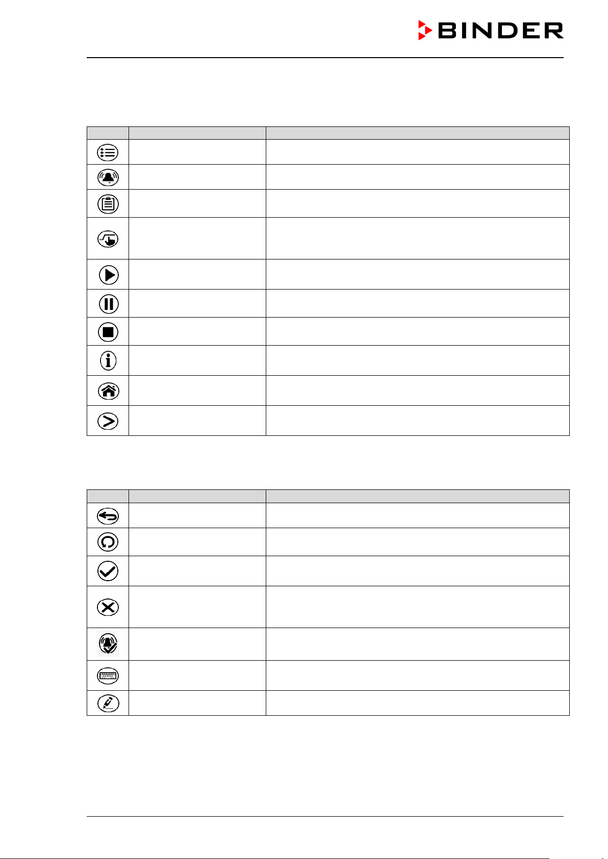
Icon
Signification
Function
Icon
Signification
Function
8.3 MB2 controller icons overview
Navigation icons in Normal display
Main menu Access from Normal display to the main menu
Alarm Access from Normal display to the list of active alarms
Event list Access from Normal display to the event list
Access from Normal display to the setpoint entry menu: setpoint
Setpoint setting
entry for Fixed value operation, turning on/off temperature and/or
pressure control, safety controller settings
Program start
Program pause Pause a running time program
Program cancelling Cancel a running time or week program
Information
Normal display
Change view
Functional icons in individual menus
Back Return from each menu to Normal display
Update Update the event list and alarm messages
Start a previously entered time or week program,
continue a paused time program
Information on program operation, setpoints, actual values, and
the safety controller
Return from program display or chart recorder display to Normal
display
Toggle between Normal display, program display, and chart recorder display
Confirm
Take over the entries and exit the menu / continue menu sequence.
Exit the menu / cancel menu sequence. Entries are not taken
Close
over. When terminating a menu sequence, an informatio n window appears, which must be confirmed.
Reset alarm Acknowledge the alarm and mute the buzzer.
Change keyboard
Change between uppercase and lowercase characters, digits
and special characters
Edit Edit settings of time and week programs
VDL (E3.1) 10/2020 Page 77/196
Page 78
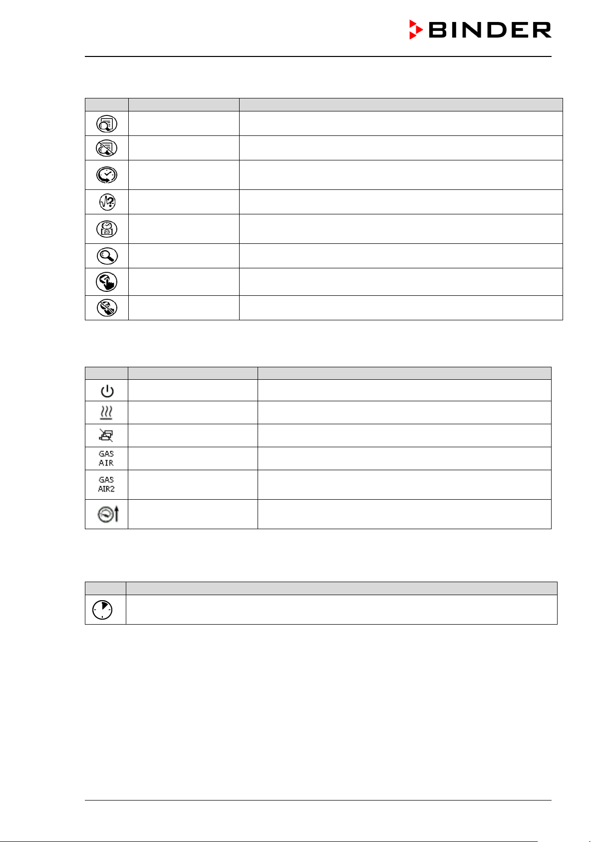
Icon
Signification
Function
Icon
Text information
Condition
Icon
Information
Functional icons in the chart recorder display
Show legend Show legend
Hide legend Hide legend
History display
Pause chart recorder and change to history display. Data recording
continues.
Curve selection Go to “Curve selection” submenu in the history display
Go to “Search” submenu in the history display to select the required
instant
Search
Zoom Go to “Zoom” submenu in the history display to select the zoom factor
Show scroll buttons Show scroll buttons in the history display to scroll to an instant
Hide scroll buttons Hide scroll buttons in the history display to scroll to an instant
Information icons referring to chamber conditions
“Standby” Chamber is in Standby mode
“Heating active” Chamber is heating up
“All valves are closed” All valves are closed
“GAS/AIR” Ventilation via regular connection “GAS/AIR” (4)
“GAS/AIR 2”
“Press.thresh. not
reached”
Information icon for data processing
Waiting icon: Data processing is running.
Remaining time to touch the display when calibrating the touchscreen.
Ventilation via optional connection “GAS/AIR2” (5)
Regular connection “GAS/AIR” (4) deactivated.
Pressure threshold of 100 mbar not reached
VDL (E3.1) 10/2020 Page 78/196
Page 79

8.4 MB2 controller operating modes
The MB2 program controller operates in the following operating modes:
• Fixed value operati ng m ode
The controller operates as a fixed-point controller, i.e., s et-points for tem perature and pressure can be
defined, which are then maintained until the next manual change (chap. 10.1.1).
• Timer program operation
Stopwatch function: during an entered duratio n the controller constantl y equilibrates to the setpoi nts
entered in Fixed value operation mode.
• Time program operation
An entered time program for temperature and pressure is running. T he controller offers 25 program
memory places with 100 pr ogr am sections each. The total num ber of pr ogram sections of all progr ams
is unlimited
• Week program operation
An entered week pr ogram for temperature and press ure is running. The control ler offers 5 program
memory places with 100 switching points each. The switching points can be distributed over all days of
the week.
8.4.1 MB2 controller menu structure
Main menu: program settings, further information, “Service” submenu.
The “Settings” submenu allows general configuration of the controller.
List of active alarms chap. 16.2
Access to the event list chap. 13.5
Use the navigation icons in the screen footer in
Normal display to access the desired controller
functions.
The available functions depend on the current au-
thorization level “Service”, “Admin” or “User”
(chap. 12.1. This is selected either during login or
can be available without password protection.
chap. 8.4.2
Setpoint entry for Fixed value operation, Standby mode, turning on/off
temperature and/or pressure control, safety controller settings
Start/ pause/ cancel an already entered, respectively a running time
program or start / cancel an already entered, respectively a running
week program
Unless noted otherwise, the figures show the functional range, which is available for the user with “Admin”
authorization level.
VDL (E3.1) 10/2020 Page 79/196
chap.
10.1.1,
11.5, 14.2.2
chap. 18.1,
18.2, 19.1
Page 80

8.4.2 Main menu
The main menu prov ides a cces s to the genera l configur ation of the c ontroller as well as to progr am entr y
and the user administrat ion. Additionally, there ar e support functions like a contact page or the d isplay
calibration depending on the available angle.
Press the Main menu icon to access the main menu from Normal Display.
Press the Back icon to return from each setting menu to Normal Display.
The main menu provides the following functions and submenus.
User management: login and logout, password management
Chamber information chap. 13.8
“Settings” submenu (not visible for user with
“User” authorization level)
“Programs” submenu (not visible for user
with “User” authorization level)
“Service” submenu chap. 8.4.4
BINDER Service contact page chap. 13.6
Calibrating the touch screen chap. 13.4.2
Back to Normal Display
“Settings” submenu
• Settings of many general controller functions and network settings (chap. 13).
chap. 12.1
chap. 13
chap. 18 und 19
• Available only for users with “Service” and “Admin” authorization level
“Service” submenu
• Access to service data, controller reset to factory settings (chap. 8.4.4)
• Available onl y for users with “Service” and “A dmin” authorization level. Full f unctional range only for
BINDER Service (users with “Service” authorization level).
“Programs” submenu
• Access to the controller’s program functions (chap. 17, 18, 19)
• Available only for users with “Service” and “Admin” authorization level.
VDL (E3.1) 10/2020 Page 80/196
Page 81

Setting the display brightness, continuous operation and screen saver
Settings for the measurement chart: storage interues
erance range alarm
Configuration of the e-mail server, assignment of
e-mail addresses
Serial number of the chamber, setup version of
the controller software
8.4.3 “Setti ngs” submenu
The “Settings” submenu is av ailable for users with “Service” or “Admin” authorization level. It serves to
enter date and tim e, select the l anguag e for the contro ller m enus and the des ired t em peratur e unit and t o
configure the controller’s communication functions.
Path: Main menu > Settings
Setting the temperature unit, menu language… chap. 13.1,
Setting date and time chap. 13.2
chap. 13.4
val, storage values, minimum and maximum val-
Setting the tolerance range and delay time for tol-
(not used)
Entry of the MAC address and IP address chap. 20.1
Password protection for web server access chap. 20.2
Back to main menu
chap. 22.2
chap. 15
chap. 20.3
8.4.4 “Service” subm enu
The “Service” submenu is available for users with “Service” or “Admin” authorization level. When logged-in
with “Admin” authorization level the user will find information to tell the BINDER Service in service case.
Path: Main menu > Service
chap. 13.8
(view with “Admin” authorization level)
VDL (E3.1) 10/2020 Page 81/196
No function
Information for BINDER Service
Reset to factory settings
Back to main menu
Page 82

8.5 Principle of controller entries
In the selection and entr y menus there ar e icons displa yed in the footers which you can use to t ake over
the entry or cancel it.
Selection menu (example)
After completing the settings there are the following possibilities:
Press the Confirm icon to take over the entries and exit the menu or continue the menu sequence.
Press the Close icon to exit the menu or cancel the menu sequence without taking over the
entries.
When terminating a menu sequence, an information window appears, which must be confirmed.
Entry menu (example)
8.6 Performance during and after power failures
During a power failure, all controller functions are shut down.
If there is a vacuum and venti lation is r equire d during t he durat ion of the power f ailure, t h is is poss ible via
the emergency ventilation (chap. 9.9.3).
After the power returns, all functions return to the same status the chamber had before power failure.
All settings and set point values remain in the memory during power failure.
• If the Stand by mode had b een activated pr ior to the power f ailure, the cham ber remains off after the
power returns. To operate it you must sign in with a higher authorization level and deactivate the standby
mode.
• If the Standby mode had been deactivated prior to the power failure, operation continues after the power
returns with previously entered parameters. If the pressure reaches or falls below the required pressure
threshold of 100 mbar, the heater turns on depending on the setpoint.
After the power returns, th e controller continues to f unc tion in th e or i gin al operating mode it was in pr ev iously before the power failure occurred:
• Performance after power failure in Fixed value operation mode
All functions return to the same status the chamber had before power failure. The set-points are immediately resumed.
• Performance after power failure during Timer operation
The set-points whic h had b een acti ve at the m om ent of program start ar e resum ed. Program run continues.
VDL (E3.1) 10/2020 Page 82/196
Page 83

• Performance after power failure during Time program operation
The program is res umed at the point where th e int err uptio n oc cur r ed with t he lat e s t s et -poi nts reac h ed
during the program run.
• Performance after power failure during Week program operation
The week program continues with the values corresponding to the current time.
Power failure and power return are noted in the Event list (chap. 13.5).
If during power failure an alarm has occurred (e.g., tolerance r ange, saf ety controller) , confirm the alarm .
See chap. 16.3.
9. Start up and performing the drying process
With regard to o perating the vacuum drying oven VDL and t o the inst allation locat ion, p leas e obs erve t he
relevant national regulation s (for Germ any in partic ular: DGUV guidelines 213-850 o n safe work ing in laboratories, issued by the employers’ liability insurance association; Industrial Safety Regulation (BetrSichV); Ordinance on Hazardous Substances (GefStoffV); Technical Regulations on Industrial Safety and
Health (TRBS 1201 Part 1).
Note: Warming chambers may release odors in the first few days after commissioning. This is not a quality
defect. To reduce odors quickly we recommend heating up the chamber to its nominal temperature for one
day and in a well-ventilated location.
Do not start up the chamber without technical ventilation (chap. 5.2.2).
9.1 Requirements for safe commissioning
Prior to turning on the chamber, the following points must certainly be met:
• Installation of the chamber (chap. 6) performed in compliance with the installation guidelines and ambi-
ent conditions (chap. 5)
• Compres sed air connection established for sweeping the electrical installation room, the pr eheating
chamber (heating area between inner and outer chamber) and the controller housing. The compressed
air supply line prov ided by the operator m ust be equipped with active m onitoring of the defined inl et
pressure (2 bar).
• Vacuum supply connected (chap. 6.5)
• If required: Inert gas connection established (chap. 6.6)
• Equipotential bonding established (chap. 6.8)
• Observing all safety instructions
• Upon initial commissioning: Test before initial commissioning performed and passed (Chap. 7.4)
• Upon recommissioning after maintenance / repairs / chan ges requiring review: Test performed and
passed (Chap. 7.5)
• Technical ventil ati on ac tivat ed
• Power connection established (chap. 6.9).
VDL (E3.1) 10/2020 Page 83/196
Page 84

□
□
□
□
□
□
□
□
9.2 Overview of the drying process
Required measures for operation with solvent-containing substances, which may be able to form an explosive mixture with air:
Starting situation
• The vacuum drying oven and additional equ ipment have been set up and installed in accordance with the i nstructio ns in this manual, the instr uctions of the oper ator and the relevant regulations. Equipotential bonding according to the grounding concept is ensured
• The auto-ignit ion t emperature of the solvent has be en deter mined from its safety specific ations
In the case of solvent mixtures, use the lowest auto-ignition temperature.
• All users have been trained and are familiar with the safety plan and the required measures.
• The vacuum source is connected and ready for operation
• The technical ventilation is activated.
□
□
• The com pressed air supply is connected an d ready for operation. The m onitoring of the
defined inlet pressure (2 bar) is active.
Sweeping the area for electrical equip m ent, the preheating chamber, and controller housing
(triangular instrument box)
• Turn the pres sure regulator on the chamber rear until the clamping rin g touches the lower
stop (turn clockwise).
• Open the sweeping plug on the chamber rear and the USB cover on the controller housing.
• Sweep t he electrical i nstallation room, the preheating cham ber and the controller housing
with compressed air for the specified duration (chap. 9.3.2) at maximum overpressure
• Close the sweeping plug on the chamber rear and the USB cover on the controller housing
• Now the pressure regulator can be turned back (counter-clockwise rotation) until the clamp-
ing ring touches the upper stop. (only tighten to the stop by hand)
• Check on the manometer that an overpressure of at least 25 Pa (recommendation: >40 Pa)
has been reached
Loading and starting the drying pr ocess
• Make sure that the technic al venti lat ion is activated
• Make sure that equipotential bonding has been established according to the grounding con-
cept
• Make sure that the s weeping tim es of the elect rical ins tallation room , preheating chamber,
and controller housing (triangular instrument box) have been observed
□
□
□
□
□
□
• Make sure that the c ompressed air supply for swee pi n g the e lectr ical installation area, preheating chamber, and controller housing is still open. Check the excess pressure of at least
25 Pa on the manometer (recommendation: >40 Pa).
• In case of Standby mode turn on the vacuum drying oven on the controller
• Set the desired temperature setpoint on the controller.
• Set the safety controller to a suitable value.
Recommended setting: safety controller m ode: Limit, safet y controller value approx. 5 °C
above the temperature set-point
VDL (E3.1) 10/2020 Page 84/196
□
□
Page 85

□
□
□
• Make sure that the user's equipment is ESD protected.
• Place the material to be dried in the chamber.
• Set the pressure set-point on the controller.
Heating will start only when a vacuum corresponding to the pressure threshold of 100 mbar)
is reached.
The drying process is running.
After completing the drying process or when cancelling the drying process
When the pressure drops to the pressure set-point, the drying process is finished. If the drying monitoring (chap. 11.6) is activated, a corresponding message is displayed.
• Make sure that the technic al venti lat ion is acti vat ed
• Make sure that equipotential bonding has been established according to the grounding con-
cept
• For ventilation, set the pressure set-point to atmospheric pressure
• Switch the vacuum drying oven on the controller to standby mode (not completely de-ener-
gized)
• Make sure that the user's equipment is ESD protected.
• Remove the drying material
• Continue sweeping the electrical installation area, preheating chamber and controller hous-
ing with an overpressure of at least 25 Pa (recommendation: >40 Pa) for at least 10 minutes
(recommended). Check the excess pressure on the manometer. Only then shut off the compressed air supply.
□
□
□
□
□
□
For emptying the pump
• Make sure that the pump is turned off.
• Make sure that the technic al venti lat ion is acti vat ed
• Make sure that equipotential bonding has been established according to the grounding con-
cept
• Make sure that the user's equipment is ESD protected.
• Remove the full condensate catchpot of the pump
Before starting a new drying process
In case of a new solvent with a different auto-ignition temperature:
• Determine the au to-ignitio n tem perature of the solvent from its safety specif ications. In the
case of solvent mixtures, use the lowest auto-ignition temperature
• Make sure that the technic al venti lat ion is acti vat ed
• Make sure that equipotential bonding has been established according to the grounding con-
cept
• Sweep the area for electrical equipment, preheating c hamber and the controller hous ing
with compressed air at maximum overpressure for a defined time (chap. 9.3.2).
• Turn on the cham ber and check the settings (dr ying temperature, pressure set-point and
safety controller setting)
• Now you can load the chamber and start the new drying process. Follow all safety measures
□
□
□
□
□
□
VDL (E3.1) 10/2020 Page 85/196
Page 86

(11) (9) (10)
9.3 Sweeping the area for electrical equipment, the preheating chamber, and the controller housing (triangular instrument box) with compressed air
To s weep the area f or electrical equ ipment, the preheatin g chamber, and the controller housi ng, activate
the customer's compressed air supply.
The compressed air supply line provided by the operator must be equipped with active monitoring of the defined inlet pressure (2 bar), which clearly indicates a drop and increase in the
inlet pressure outside the permissible tolerance of ±0.2 bar.
9.3.1 Sett ing the pressure regulator for sweeping with compressed air
After opening the pressure regulator on the chamber rear (turn clockwise), the area for electrical equipment
of the oven, the preheating cham ber (the heater area between the inn er a nd outer chamber) and th e c ontroller housing will be s wep t. Compr essed air is used and t hen releas ed into the surrounding atm osphere
independent of the oven’s operating state.
Compressed air sweeping must be in operation for a defined time (chap. 9.3.2) before turning on the chamber. It remains in operati on dur ing the e ntire us e of th e cham ber (load ing, dr ying, rem oval of the mater ial
to be dried), with an overpressure of at least 25 Pa (recommendatio n: >40 Pa). This operating point is
defined on the press ure regulator when the clam ping ring touches the upper stop. After terminatin g the
drying procedure and turning off the cham ber it is recommended to continue sweeping for approx. 10
minutes.
On the chamber front there is an analog pressure display (manometer) to show the existing overpressure.
Figure 22: Pressure regulator and sweeping plug
for compressed air sweeping on the chamber rear
(9) Pressure regulator for compressed air sweeping
(10) Connection for compressed air sweeping / overpressure
(11) Outlet with sweeping plug for compressed air sweeping before start-up
Figure 23: analog pressure display (manometer)
for compressed air sweeping on the chamber
front
VDL (E3.1) 10/2020 Page 86/196
Page 87

9.3.2 Sweeping before starting up / restarting the chamber
Before turning on the VDL it is mandatory to sweep the area for electrical equipment, the preheating chamber and controller housing with compressed air at maximum overpressure for a defined time.
Compressed air sweeping before start-up takes place in two steps. Be sure to follow the given
order.
Sweeping the electrical installation room, preheating chamber and controller housing (instrument
triangle)
• Turn the pressure regulator until the clamping ring touches the lower stop (turn clockwise). This gives
the maximum overpressure.
• Open the sweeping plug on the chamber rear next to the pressure regulator
• Check that compressed air flows out of the sweeping plug (caution, the outflowing air may be hot)
• Open the USB cover on the controller housing (instrument triangle)
• Check if compressed air is coming out of the USB cover (caution, the outflowing air may be hot)
• Sweep with maximum overpressure for at least the following duration
VDL 23: 20 minutes
VDL 56: 30 minutes
VDL 115: 40 minutes
• Then close the sweeping plug on the chamber rear.
• Also connect the USB cover on the controller housing (instrument triangle)
• Now the pressure regulator can be turned back (counter-clockwise rotation) until the clamping ring
touches the upper stop. (Only tighten to the stop by hand)
• Check that there is an overpressure of at least 25 Pa (recommendation: >40 Pa).
9.3.3 Sweeping during chamber operation
Sweeping the electrical inst allation room , the preheating cham ber and control ler housin g mus t take place
with an overpressure of at least 25 Pa (recommendation: >40 Pa) during the entire operation of the vacuum
drying oven. This oper ati ng po int is d ef ine d o n t he pr e s sur e regulator when the clamping ring touches the
upper stop. Also after term inati on or canc ellatio n of the dr ying proces s c ontinue d sweeping for at least 10
minutes is recommended.
Figure 24: Pressure regulator with defined setting at the upper stop
VDL (E3.1) 10/2020 Page 87/196
Page 88

DANGER
Explosion hazard by solvent-containing air penetrating and concentration in the
electrical area of the chamber and at the heater.
Serious injury or death from burns and / or explo sion pressure.
Make sure that sweeping the area for electrical equipment, preheating chamber, and
controller housing with compressed air for the defined time (chap. 9.3.2) at maximum
overpressure has been done before turning on the chamber.
Make sure that sweeping the area for electrical equipment, preheating chamber, and
controller housing with compressed air with an overpressure of at least 25 Pa (recommendation: >40 Pa) takes place during the entire operation.
Ensure that the compressed air supply line provided by the operator is equipped with
active monitoring of the defined inlet pressure which clearly indicates a drop and increase in the inlet pressure outside the permissible tolerance of ± 0.2 bar
Proceeding
• The sweeping plug on the chamber rear and the USB cover on the controller housing must be closed
• Adjust the pressure regulator until the clamping ring touches the upper stop. (Only tighten to the stop by
hand)
• Check this display during operation of the chamber. In all operating states, the value on the manometer
must show an overpressure of at least 25 Pa. Recommended value: >40 Pa.
Regarding use of the USB connection during chamber operation please observe the instructions given in chap. 21.1.
9.3.4 Sweeping after completion of chamber operation (recommended):
• You can stop sweep ing 10 m inutes af ter tur ning of f the c ham ber: Close th e pres s ure regu lator to ( turn
counterclockwise).
• Then you can close the compressed air supply.
• Check on the manometer that there is no longer any overpressure.
9.4 Condition after establishing the power connection
Only trained personnel with key-authorization may work on the VDL vacuum drying oven.
Prior to establishing the power connection, the following points must certainly be met:
• Installation of the chamber (chap. 6) performed in compliance with the installation guidelines and ambi-
ent conditions (chap. 5)
• Vacuum supply connected (chap. 6.5)
• If required: Inert gas connection established (chap. 6.6)
• Equipotential bonding established (chap. 6.8)
• Upon initial commissioning: Test before initial commissioning performed and passed (chap. 7)
• Technical ventil ati on is activated
• Sweeping the area for electrical equipment, preheating chamber, and controller housing with com-
pressed air for the defined time (chap. 9.3.2) at maximum overpressure has been done
Establish the power connection: connect the power plug (chap. 6.9). Connect the power supp l y onl y when
needed, and disconnect it when the chamber is not in use for an extended period.
VDL (E3.1) 10/2020 Page 88/196
Page 89
After establishing power supply the pilot lamp in the controller housing shows readiness for operation.
The authorization l evel is “ User” . To be able t o us e the e ntire funct ionalit y of the control ler, log in with t he
desired authorization level.
All parameters, set-points and settings remain the same as before turning off.
• If the Stand by mode had b een activated pr ior to the power f ailure, the cham ber remains off after the
power returns. To operate it you must sign in with a higher authorization level and deactivate the standby
mode.
• If the Standby mode had been deactivated prior to the power failure, operation continues after the power
returns with previously entered parameters. If the pressure reaches or falls below the required pressure
threshold of 100 mbar, the heater turns on depending on the setpoint
9.5 Standby mode Turning on and off the vacuum drying oven
Before turning on the chamber, the following points must surely be met:
• Equipotential bonding established (Chap. 6.8)
• Technical ventil ati on is activated
• Sweeping the area for electrical equipment, preheating chamber, and controller housing with com-
pressed air for the defined time (chap. 9.3.2) at maximum overpressure has been done
Activate the chamber only as required. Switch the chamber to standby mode when it is not in use.
In standby mode no solvents may remain inside the chamber!
Before turning off the chamber (activating standby mode), completely remove all solvents from
the chamber and its surroundings.
All settings and target values remain saved in standby mode.
If a program is running, it will be canceled by activating the standby mode
In Standby mode, the heating is off, and all valves are closed. Heating control and pressure control are off.
To completely separate the chamber from the power supply, you must disconnect the power plug.
For decommissioning observe the guidelines in chap. 27.2.
Required authorization: “Admin”.
Press the Setpoint setting icon to access the “Setpoint” setting menu from Normal display.
Path: Setpoint > Fixed value operation setpoints > Functions on/off
In this menu you can activate and deactivate the Standby mode .
VDL (E3.1) 10/2020 Page 89/196
Page 90

Activating the Standby mode (turning off the chamber):
“Functions on/off” menu
Mark the checkbox of the function “Standby” to activate
it and press the Confirm icon.
In the “Setpoints” menu press again the Confirm icon.
The controller changes to Normal display.
When the function “Standby” is activated, the “Standby” icon is displayed in the screen header
in Normal display. Press the flash icon next to the information icon to display the corresponding
text information “Standby” (information messages, chap. 16.1).
When the controller display is dark in standby mode, press on the touchscreen to activate it for 10 seconds.
Deactivating the Standby mode (turning on the chamber
To deactivate the “Standby” function, unmark the checkbox.
9.6 Controller settings upon start up
Depending on the functions activated in the controller, various settings can be requested directly after turning on the chamber.
Then you should assign a password for the operating level (chap. 12).
The window “Language selection” enables the language selection, in case that it’s activated in the “Start-
up” menu. Afterwards occurs a request of the time zone and the temperature unit.
The controller wi ll func t ion i n th e ope rating mode, which was act ive bef ore the las t shut-dow n. It c o ntr ols
temperature and pr essure in fixed value oper ating mode to the last enter ed values and in the program
mode to the set points achieved beforehand.
Locked operation
Provided that the us er a dministration has been act iv at ed b y th e as s ignment of passwords for th e dif f er ent
authorization types, the controller operation is first lock ed after turning on the unit, recogn izable by the
closed lock icon in the header.
VDL (E3.1) 10/2020 Page 90/196
Page 91

In the locked view the controller provides all display functions. No setting functions are available.
The setpoints are sh aded (light grey) in n ormal displa y. Changing them by direct entry in th e fixed value
operating mode is not p ossible. T he function al icons f or setpoint entr y and pro gram start in the foot er are
without function.
After turning on the unit, user log-in is required to operate the controller (chap. 12.2).
Operation without user log-in / without password-protection
If the password functi on h a s been deac t ivated, after turning on the unit w it hou t user log-in there are those
controller functions a vailabl e, which cor respo nd to the hig hest aut horizat ion le vel with out a pas swor d protection. There is no lock icon in the header.
9.7 Loading
Without technical ventilation the chamber must not be loaded with material containing solvents.
The chamber cannot be loaded when turned off / in stan dby mode .
Before loading the material to be loaded, note:
When loading the chamber also in the context of intended use, an explosive mixture may form in the working
space. Therefore, a safety area of at least. 1 m in front of the oven must be considered.
• Ensure equipotential bonding. The accessible installation and operating surface of the equipment must
be conductive. This insta lla tion a nd o perating surface must be connected w ith t he vacuum drying oven
according to the grounding plan (Chap. 6.8).
• The personal prot ective equipm ent (PPE) of the operatin g personnel m ust be implemented ESD pro-
tected. This applies also to gloves.
• Activate the technical ventilation (extraction):
The operator shall pro vide ac tive ventil ation (tech nical ven tilation ac cording to c ountry-s pecific regula-
tions (TRBS 2152 Part 2 for Germany) prior to commissioning of the chamber. It must include the entire
installation area of the vac uum dr ying oven. Loading must take place under techni cal ventilati on in the
safety area in front of the oven.
• Introduce on l y those s ol ven t s f or which the aut o-ignition temperature and the maximum drying temper-
ature (safety tem perature) have been determ ined and setting on the safety contr oller has been per-
formed.
Acc. to IEC 60079-0, onl y substances with an auto-ignition tem perature above 200 °C / 392 °F may be
introduced into the ch amber. T his chamber is NOT suitable for drying substances with an auto-igni-
tion temperature below 200 °C.
VDL (E3.1) 10/2020 Page 91/196
Page 92
DANGER
Explosion or implosion hazard and danger of poisoning by introduction of unsuitable loading material.
Serious injury or death from burns and / or explo sion pressure or by poisoning.
∅ Do NOT introduce any substance with an auto-ignition temperature below 200 °C /
392 °F into the chamber.
∅ Do NOT introduce any substance which is combustible or explosive at working temper-
ature into the chamber.
∅ Do NOT introduce energy sources such as batteries or lithium-ion batteries into the
chamber.
∅ Do NOT introduce any substance, which fall under the explosives law into the chamber
∅ Do NOT introduce any combustible dust into the chamber.
∅ Do NOT introduce any substance which could lead to release of toxic gases into the
chamber.
If the auto-ignition temperature of a solvent c on tai ned i n th e drying material is exceeded during the drying
process, there is an immediate risk of fire and explosion. Make sure that the auto-ignition temperature of a
solvent contained will NEVER be reached.
DANGER
Fire and explosion hazard when exceeding the auto-ignition temperature of the solvent.
Serious injury or death from burns and / or explo sion pressure.
Take the auto-ignition temperature from the safety specifications of the solvent. In the
case of solvent mixtures, use the lowest auto-ignition temperature.
Correctly set the maximum drying temperature (safety temperature) on the temperature
safety device according to the information panel “Temperature setting”.
Introduce measures to prevent mixing up the material to be dried.
Before starting a new drying process with a different auto-ignition temperature, check
the auto-ignition temperature with the safety specifications of the solvent.
If, during loading materia l containing solvents f alls down, it is possible that t he solvent or solvent vapor s
will spread outside the load ing area, e.g. to the sid e of or below the cham ber. The cham ber must be disconnected from the po wer imm ediately (pull out th e power plug or operate e.g., a customer's em ergency
stop switch).
The chamber is not to be installed and operated in pot enti al ly explos i ve areas .
DANGER
Explosion hazard due to explosive mixtures in the vicinity of the equipment.
Serious injury or death from burns and / or explo sion pressure.
∅ Ensure that NO solvents or explosive solvent-air mixtures are located in the area
around the chamber.
Disconnect the chamber from the power immediately if there is explosive atmosphere in
the area around the chamber outside the indicated loading area.
VDL (E3.1) 10/2020 Page 92/196
Page 93
9.8 Evacuation
Starting situation: The vacuum pump / vacuum system is connected and ready for operation.
Preparation:
• Make sure that the “ Manual ventilation” plug (7) for emergency venti lationin case of a power failure,
which is located on the chamber rear, is closed
• Make sure that the pressure control is activated.
• Turn on the vacuum pump. The pump shall continue running during the entire drying procedure.
• Set the desired pressure set-point on the controller (chap. 10).
• Monitor the internal pressure on the controller display
As long as there is a vacuum, never try to open the oven by force.
9.9 Breaking the vacuum (flooding)
9.9.1 Venti lation after completing the drying procedure (flooding with ambient air or
inert gas)
The duration of the dr ying procedure can be determ ined via t he press ure disp lay on the contr oller. W hen
the decreasing pres sure re aches the s et-poin t value, t he dr ying process is com pleted. If the dryin g monitoring (chap. 11.6) is activated, a corresponding message is displayed.
To break the vacuum (ventilation) after completing the drying procedure, set the desired pressure set-point
to atmospheric pres s ure ( c hap. 10). The ventilation valv e o pens , an d ambient air or inert g as flow into the
inner chamber.
Regularly the universal connection for inert gas / ambient air “GAS/AIR” (4) is used for ventilation.
Chambers can be equipped as an option with an additional universal connection for inert gas / ambient air
“GAS/AIR2” (5), which can be used alternati vel y. To do this, t he contr oller f unctio n “GAS/ AIR 2” ser ves to
close the valve of the standard connection “GAS/AIR” (4). Then the valve of the optional connection
“GAS/AIR 2” (5) is used for ventilation (chap. 11.2). This allows conv enient switchin g when both con nections are used differently (e.g., for inert gas and ambient air).
Ambient air is sucked in through the universal connection for inert gas / ambient air (4) or (5). The ambient
air is introduced int o the lo wer part of the rear pa nel of the inner cham ber an d is evenl y distrib uted in t he
inner chamber. T his sup pl y of am bient air b y un der-f loodi ng pr event s turb ulence of pulver i zed drying material.
Following ventilation, remove the loading material.
If no further drying pr ocess is to be c arried out, s witch the ch amber to standb y mode on t he controller or
pull the mains plug to switch off the chamber completely.
9.9.2 Operation with inert gas
When operating the VDL vacuum drying oven with inert gas, correctly follow the technical ventilation
measures, as desc ribed in the DGUV guidelines 213-850 on safe work ing in laboratories, issued by the
employers’ liability insura nc e association (for Germany).
During operation with inert gas, the chamber is supplied with an oxygen displacing gas (e.g. N
). Inert gases
2
in high concentrations are hazardous to health. They are colorless and almost odorless and therefore practically imperceptible. I nhalation of inert gases can c ause drowsiness up to respira tory arrest. When the O
2
content of the air decreases below 18%, t here is risk of death f rom lack of oxygen. An y gas that might
escape has to be led out via good room ventilation or a suitable exhaust system.
VDL (E3.1) 10/2020 Page 93/196
Page 94

DANGER
Risk of suffocation due to high concentration of inert gas.
Death by suffocation.
∅ Do NOT set up chambers in non-ventilated recesses.
Ensure technical ventilation measures.
Respect the relevant regulations for handling these gases.
When decommissioning the vacuum drying oven, shut off the inert gas supply.
Install a pressure reduc er for inert gas operation. Set the press ure reducer to a pressure sligh tly above
ambient pressure. Ensur e that the pressure reducer will open. D o not c h ang e this setting in order to avoid
perturbation inside the oven and release of big quantities of inert gas after flooding the VDL.
Following evacuation, an inert gas, e.g., nitrogen, is led into the inner chamber via the connection
“GAS/AIR” (4) or the optional connection “GAS/AIR 2” (5) until pressure compensation with the atmosphere
occurs. Depending on the individual application, you can perform a second evacuation and repeat the inert
gas flooding.
When the inert gas fine dosing valve is open, a maxim um of approx. 0.6 m³/h gas flows into the inner
chamber. The introduction of inert gas by under-flooding in the lower region of the inner chamber rear wall
and the extraction at the inner chamber ceiling allow an effective inert gas flushing.
9.9.3 Venti lation / breaking the vacuum in case of a power failure
The emergency ventilation is intended for the case of a completed drying process
To be able to open the cham ber in case of a power failure, rem ove the “Manual ventilation” plug (7) for
emergency ventilation, which is located on the chamber rear.
As long as there is a vacuum, never try to open the oven by force.
Make sure that the drying procedure is complete before breaking the vacuum. Otherwise, you
should wait for the power to return to continue the drying procedure.
DANGER
Explosion hazard through the formation of an explosive atmosphere in the presence of hot surfaces.
Serious injury or death from burns and / or explo sion pressure.
∅ Do NOT remove the “Manual ventilation” plug, as long as the drying process is still run-
ning.
9.9.4 Venti lation before completing the drying procedure (flooding wit h ambient air or
inert gas)
If possible, avoid term inating the dr ying proces s. If it is nevertheless to be d one, it is es sential to obs erve
the following instructions!
Safety during the drying process: The vacuum during dr ying prevents the presence of an ex plosive
atmosphere in the int erior of the cham ber. At the start of the drying proces s, the heater is th erefore onl y
released at a pressure of 100 mbar. In addition, the m axim um temperat ure is lim ited so that, with correc t
load, there is no risk of ignition from hot surfaces.
VDL (E3.1) 10/2020 Page 94/196
Page 95

Error: If inc orrec t loading w ith an inadm is sible solve nt ( auto-ig nition tem per ature <200 ° C) has occurred,
proceed as follows
• Disconnect the power plug and turn off the pump.
• Let the chamber cool down to room temperature.
• Do NOT remove the “Manual ventilation” plug.
• Only ventilate when the interior temperature has cooled to room temperature. Only then open the door.
Hazard when opening the door after ventilation: After incorrect loading, open the door o nly when the
inner temperature has sunk to ambient temperature.
Prior to a termination of a not completed drying process make sure that the auto-ignition temperatureof the solvent has been determined correctly, and that the drying temperature
reached far below this. In case of doubt, do not interrupt the drying process!
Proceeding to terminate the drying process:
• Set the temperature set-point to approx. ambient temperature
• Let the chamber cool down to ambient temperature
• Set the pressure set-point to approx. atmospheric pressure
DANGER
Explosion hazard through the formation of an explosive atmosphere in the presence
of hot surfaces after incorrect loading
Serious injury or death from burns and / or explosion pressure.
∅ Do NOT use ambient air to break the vacuum as long as the chamber is hot. Do NOT
remove the “Manual ventilation” plug as long as the drying process is still running.
Let the chamber cool down to room temperature before opening the door.
9.10 Unloading the loading material
Do not unload the loading material without technical ventilation.
Note the following points before unloading the loading material:
When unloading the loading material also in the context of intended use, an explosive mixture may form in
the working space. Therefore, a safety area of min. 1 m in front of the oven must be considered.
• Activate Standby mode on the controller before opening the door.
• Ensure equipot ential bo nding: The ac cessible installat ion and operat ing area in front of the equipm ent
must be conductive. This installation and operating area must be connected to the vacuum drying oven
and other equipment according to the grou ndi ng plan (chap. 6.8).
• Activate the technical ventilation (extraction):
The operator shall provide activ e extraction ( technical ventilation according to c ountry-specif ic regula-
tions – TRBS 2152 Part 2 for German y) prior to commission ing the oven. Extracti on must include the
entire installation area of the vacuum drying oven. Unloading the loading material must take place in the
safety area in front of the oven with technical ventilation.
• The personal protective equipment (PPE) of the operating personnel must be implemented
ESDprotected.
• Sweep the area for electrical equipment, preheating chamber, and controller housing at least 10
minutes with compressed air (recommended).
VDL (E3.1) 10/2020 Page 95/196
Page 96

9.11 Removing the full condensate catchpot of the pump
Do not remove the full condensate catchpot of the pump without technical ventilation
Note the following points before removing the condensate catchpot:
When removing the condensate catchpot spilling of the solvent may occur.
• Ensure equipotential bonding:
The accessible installation and operation area of the equipment must be conductive. This area and the
vacuum pump must be connected with the vacuum drying oven according to the grounding plan (Chap.
6.8).
• Activate the technical ventilation (extraction):
The operator shall provide activ e extraction ( technical ventilation accordi ng to countr y-specific reg ula-
tions – TRBS 2152 P art 2 for Germany) prior to m anipulating the condensate catc hpot of the pump.
Extraction must include the entire installation area of the VDL and the vacuum pump, especially the area
of the catchpot (when removing it) and the exhaust air of the vacuum pump. Removing the full conden-
sate catchpot must take place under technical ventilation.
• Use ESD protected personal protective equipment:
The personal protective e quipment (PPE) of the oper ating personnel m ust be implemented ESD pro-
tected. This includes also gloves.
9.12 Preparing a new drying process
Before starting a new drying process with a different auto-ignition temperature, determine the auto-ignition
temperature of the solvent according to its safety data sheet. In the case of solvent mixtures, use the lowest
auto-ignition temperature.
Check all settings (drying temperature, pressure set-point and safety controller setting). If appropriate,
make sure that the new temperature set-point and safety controller value are entered on the controller.
With each change of the temperature set-point, observe the safety controller setting.
VDL (E3.1) 10/2020 Page 96/196
Page 97

10. Set-point entry
Setting ranges Control ranges
Temperature
Pressure 0 mbar up to 1100 mbar 0 mbar up to 1100 mbar
Solvents and resulting vapors can ignite at excessive drying temperatures.
0.0 °C / 32 °F up to 110 ºC / 230 °F
After starting the drying procedure, the heater is activated only when the pressure reaches or
falls below the required pressure threshold of 100 mbar.
10 °C / 18 °F above ambient temperature up to
110 ºC / 230 °F
DANGER
Fire and explosion hazard when exceeding the auto-ignition temperature of the solvent due to excess drying temperature.
Serious injury or death from burns and / or explo sion pressure.
Make sure that only solvents with an auto-ignition temperature that is higher than
200 °C / 392 °F may be entered into the chamber. Check the auto-ignition temperature
with the safety specifications of the solvent. In the case of solvent mixtures, use the
auto-ignition temperature of the material with the lowest auto-ignition temperature.
In Fixed value operating mode, you can enter a temperature set-point, a pressure set-point, and the switching-state of special controller functions.
All settings made in Fixed value operating mode remain valid until the next manual change. They are saved
also when turning off the chamber or in case of toggling to Program Mode.
The values entered in Fixed value mode become valid again after the end of a program and
will then be targeted and equilibrated.
When operating without a vacuum by setting “Pressure control off” (chap. 11.5), the pressure
tolerance range function is automatically deactivated.
10.1 Set-point entry through the “Setpoints” menu
Press the Setpoint setting icon to access the “Setpoint” setting menu from Normal display.
“Setpoints” menu.
Select “Fixed value operation setpoints” to access the
individual parameters.
VDL (E3.1) 10/2020 Page 97/196
Page 98

• Select the field “Temperature” and enter the desired temperature setpoint.
Confirm entry with Confirm icon.
• Select the field “Pressure” and enter the desired pressure setpoint.
Confirm entry with Confirm icon.
When entering a value outside the setting range, the message: “Value outside of limits! (Min:
xxx, Max: xxx)” appears (xxx is a wildcard for the limits of the respective parameter). Press
the Confirm icon and repeat the entry with a correct value.
After completing t he s etti ng s , pres s th e Confirm icon to take over th e e ntr i es and exit the menu, or press
the Close icon to exit the menu without taking over the entries.
With set-point type “Limit”, adapt the safety controller (chap. 14.2) always when you changed
the temperature set-point. Set the safety controller set-point by approx. 5 °C above the controller temperature set-point.
Recommended setting: Set-point type “Limit” with safety controller set-point 5 °C.
As long as the pressure threshold of 100 mbar has not yet been reached, the icon “Pressure
threshold not reached” in the screen header in Normal display. Press the flash icon next to
the information icon to access the corresponding text information “Pressure threshold not
reached” (Information messages, chap. 16.1)
10.2 Direct setpoint entry via Normal display
Alternatively you can also enter the setpoints directly via Normal display.
Normal display. Select the setpoint you want to
change.
Example: “Temperature” entry menu. Enter the
desired setpoint and confirm entry with Confirm
icon.
VDL (E3.1) 10/2020 Page 98/196
Page 99

11. Setting special controller functions
You can set the following functions via the controller menu:
• Activate / deactivate the Standby mode (chap. 9.5)
• Use the optional connection “GAS/AIR2” (10) for ventilation (chap. 11.2)
• Close all existing fine dosing valves (chap. 11.3)
• Turning on / off temperature control (chap. 11.4)
• Turning on / off pressure control (chap. 11.5)
• Starting / terminating the drying monitoring (chap. 11.6)
11.1 Menu structure
11.1.1 “Functions on/off” menu
This chapter describes the setting with operating mode Fixed value operation. Settings for program operation are described in chap. 18.7.3 (time programs) and chap. 19.6.5 (week programs).
In the “Functions on/off” menu you can define the switching state of three controller functions.
Press the Setpoint setting icon to access the “Setpoint” setting menu from Normal display.
Path: Setpoint > Fixed value operation setpoints > Functions on/off
• Function “Standby“ (chap. 9.5)
• Function “GAS/AIR 2” (chap. 11.2)
• Function “Close all valves” (chap. 11.3)
“Setpoints” menu.
Select the field “Functions on/off”.
The functions are displayed from right to left.
“Functions on/off” entry menu.
Mark / unmark the checkbox to activate / deac-
tivate the desired function and press the Con-
firm icon
Activated function: switching status “1” (On)
Deactivated function: switching status “0” (Off)
Example:
Activated function “Standby” = 000000000000000
Deactivated function “Standby” = 000000000000000
VDL (E3.1) 10/2020 Page 99/196
1
0
Page 100

11.1.2 “Control on/off” menu
More functions are available via the “Control on/off” menu.
Press the Setpoint setting icon to access the “Setpoint” setting menu from Normal display.
Path: Setpoint > Control on/off
• Function “Temperature” (temperature control, chap. 11.4)
• Function “Pressure” (pressure control, chap. 11.5)
“Setpoints” menu.
Select the field “Control on/off”.
Mark / unmark the checkbox to activate / deactivate the
desired function and press the Confirm icon
11.2 Using the optional universal connection “GAS/AIR 2” for ventilation
Regularly the universal connection for inert gas / ambient air “GAS/AIR” (4) is used for ventilation.
The “GAS/AIR 2” function serves to close the valve of the standard connection “GAS/AIR” (4) and activate
the valve of the optional universal connection “GAS/AIR 2” (5), which is then used for ventilation
This allows convenient switching when both connections are used differently (e.g., for inert gas and ambient
air).
If you activate the “GAS/AIR 2” function on a chamber, which is NOT equipped with the optional universal connection for inert gas / ambient air “GAS/AIR 2” (5), ventilation is no longer
possible!
Press the Setpoint setting icon to access the “Setpoint” setting menu from Normal display.
Path: Setpoint > Fixed value operation setpoints > Functions on/off
“Functions on/off” menu.
Mark the checkbox of the function “GAS/AIR 2” to acti-
vate it and press the Confirm icon.
In the “Setpoints” menu press again the Confirm icon.
The controller changes to Normal display.
VDL (E3.1) 10/2020 Page 100/196
 Loading...