

Page 1

Operating Manual
VD (E2.1)
Vacuum Drying Oven
with microprocessor program controller RD3
Model Model version Art. No.
VD 23 VD023-230V 9030-0029, 9130-0029
VD 23-UL VD023UL-120V 9030-0035, 9130-0035
VD 53 VD053-230V 9030-0030, 9130-0030
VD 53-UL VD053UL-120V 9030-0036, 9130-0036
VD 115 VD115-230V 9030-0031, 9130-0031
VD 115-UL VD115UL-120V 9030-0037, 9130-0037
BINDER GmbH
Address: Post office box 102, 78502 Tuttlingen, Germany Phone: +49 7462 2005 0
Fax: +49 7462 2005 100 Internet: http://www.binder-world.com
E-mail: info@binder-world.com Service Hotline: +49 7462 2005 555
Service Fax: +49 7462 2005 93 555 Service E-Mail: service@binder-world.com
Service Hotline USA: +1 866 885 9794 or +1 631 224 4340 x3
Service Hotline Asia Pacific: +852 390 705 04 or +852 390 705 03
Service Hotline Russia and CIS: +7 495 988 15 16
Issue 07/2017 Art. No. 7001-0125
Page 2

Contents
1. SAFETY .................................................................................................................. 5
1.1 Legal considerations ........................................................................................................................... 5
1.2 Structure of the safety instructions ...................................................................................................... 5
1.2.1 Signal word panel ..................................................................................................................... 5
1.2.2 Safety alert symbol ................................................................................................................... 6
1.2.3 Pictograms ................................................................................................................................ 6
1.2.4 Word message panel structure ................................................................................................. 7
1.3 Localization / position of safety labels on the chamber ...................................................................... 7
1.4 Type plate ........................................................................................................................................... 8
1.5 General safety instructions on installing and operating the chamber ................................................. 9
1.6 Intended use ..................................................................................................................................... 11
2. DESCRIPTION OF THE EQUIPMENT ................................................................. 12
2.1 Chamber overview ............................................................................................................................ 13
2.2 VD 23 control panel........................................................................................................................... 14
2.3 VD 53 / 115 control panel ................................................................................................................. 14
2.4 Connections at the rear of the chamber ........................................................................................... 15
3. COMPLETENESS OF DELIVERY, TRANSPORTATION, STORAGE, AND
INSTALLATION .................................................................................................... 16
3.1 Unpacking, and checking equipment and completeness of delivery ................................................ 16
3.2 Guidelines for safe lifting and transportation .................................................................................... 17
3.3 Storage .............................................................................................................................................. 17
3.4 Location of installation and ambient conditions ................................................................................ 17
4. INSTALLATION AND CONNECTIONS................................................................ 19
4.1 Vacuum expansion racks .................................................................................................................. 19
4.2 Vacuum connection .......................................................................................................................... 19
4.3 Inert gas connection .......................................................................................................................... 19
4.4 Electrical connection ......................................................................................................................... 20
5. START UP ............................................................................................................ 21
5.1 Settings at the RD3 program controller ............................................................................................ 21
5.2 General indications on the RD3 program controller ......................................................................... 22
6. FIXED VALUE ENTRY MODE ............................................................................. 24
7. WEEK PROGRAM EDITOR ................................................................................. 25
7.1 Program table template for Week program Editor ............................................................................ 27
7.2 Programming example of the Week program editor ......................................................................... 28
7.2.1 Desired time function .............................................................................................................. 28
7.2.2 Proceeding overview .............................................................................................................. 28
7.2.3 Proceeding in detail ................................................................................................................ 29
8. PROGRAM EDITOR ............................................................................................. 34
8.1 Selecting between set-point ramp and set-point step ....................................................................... 34
8.1.1 Programming with setting “Ramp” (default setting) ................................................................ 34
8.1.2 Programming with setting “step” ............................................................................................. 36
8.1.3 General notes on programming temperature transitions ........................................................ 37
8.2 Set-point entry for program operation ............................................................................................... 37
8.3 Program table template ..................................................................................................................... 40
8.4 Deleting a program section ............................................................................................................... 41
9. PROGRAM START LEVEL .................................................................................. 42
VD (E2.1) 07/2017 page 2/96
Page 3

10. USER LEVEL ....................................................................................................... 45
11. PERFORMANCE IN CASE OF FAILURES .......................................................... 51
11.1 Performance after power failure ........................................................................................................ 51
11.2 Alarm messages ............................................................................................................................... 51
12. TEMPERATURE SAFETY DEVICE CLASS 2 ..................................................... 51
13. REFERENCE MEASUREMENTS. CHECKING THE TEMPERATURE IN THE
INNER CHAMBER ............................................................................................... 53
14. COMMISSIONING THE VACUUM ....................................................................... 53
14.1 Evacuation ........................................................................................................................................ 54
14.2 Breaking the vacuum (flooding with ambient air) .............................................................................. 54
14.3 Operation with inert gas .................................................................................................................... 55
15. SWITCHING CONTACTS 24V DC VIA OPERATION LINES .............................. 56
16. OPTIONS .............................................................................................................. 57
16.1 Connection kit VD (option) ................................................................................................................ 57
16.2 Vacuum module empty (without pump) (option) ............................................................................... 57
16.3 Vacuum module with chemical membrane pump VP 1.1 or VP 2.1 (option) .................................... 59
16.4 Vacuum module with speed controlled chemical membrane pump VP 3.1 and vacuum controller
(option) .............................................................................................................................................. 61
16.5 Digital pressure display (option)........................................................................................................ 63
16.6 Additional measuring channel for digital object temperature display with flexible P t 100 temperature
sensor (option) .................................................................................................................................. 63
16.7 Measuring access port vacuum 9 poles (option) .............................................................................. 64
16.8 Communication software APT-COM™ 3 DataControlSystem (option) ............................................ 65
17. MAINTENANCE, CLEANING, AND SERVICE .................................................... 65
17.1 Maintenance intervals, service .......................................................................................................... 65
17.2 Cleaning and decontamination ......................................................................................................... 66
17.2.1 Cleaning .................................................................................................................................. 66
17.2.2 Decontamination ..................................................................................................................... 67
17.3 Sending the chamber back to BINDER GmbH ................................................................................. 69
18. DISPOSAL............................................................................................................ 69
18.1 Disposal of the transport packing ..................................................................................................... 69
18.2 Decommissioning .............................................................................................................................. 70
18.3 Disposal of the chamber in the Federal Republic of Germany ......................................................... 70
18.4 Disposal of the chamber in the member states of the EU except for the Federal Republic of
Germany ........................................................................................................................................... 71
18.5 Disposal of the chamber in non-member states of the EU ............................................................... 73
19. TROUBLESHOOTING ......................................................................................... 73
20. TECHNICAL DESCRIPTION ................................................................................ 75
20.1 Factory calibration and adjustment ................................................................................................... 75
20.2 Technical data ................................................................................................................................... 75
20.3 Equipment and options (extract) ....................................................................................................... 77
20.4 Accessories and spare parts (extract) .............................................................................................. 78
20.5 Dimensions VD 23 ............................................................................................................................ 80
20.6 Dimensions VD 53 ............................................................................................................................ 81
20.7 Dimensions VD 115 .......................................................................................................................... 82
VD (E2.1) 07/2017 page 3/96
Page 4

21. CERTIFICATES AND DECLARATIONS OF CONFORMITY ............................... 83
21.1 EU Declaration of Conformity ........................................................................................................... 83
21.2 Certificate for the GS mark of conformity of the “VDE Prüf- und Zertifizierungsinstitut” (Testing and
Certification Institute of the Association for Electrical, Electronic and Information Technologies) ... 85
22. PRODUCT REGISTRATION ................................................................................ 90
23. CONTAMINATION CLEARANCE CERTIFICATE ............................................... 91
23.1 For chambers located outside USA and Canada ............................................................................. 91
23.2 For chambers located in USA and Canada ...................................................................................... 94
VD (E2.1) 07/2017 page 4/96
Page 5
Dear customer,
For the correct operation of the program controlled vacuum drying oven VD, it is important that you read
this operating manual completely and carefully and observe all instructions as indicated. Failure to read,
understand and follow the instructions may result in personal injury. It can also lead to damage to the
chamber and/or poor equipment performance.
1. Safety
This operating manual is part of the components of delivery. Always keep it handy for reference. The
device should only be operated by laboratory personnel especially trained for this purpos e and familiar
with all precautionary measures required for working in a laboratory. Observe the national regulations on
minimum age of laboratory personnel. To avoid injuries and property damage observe the safety
instructions of the operating manual.
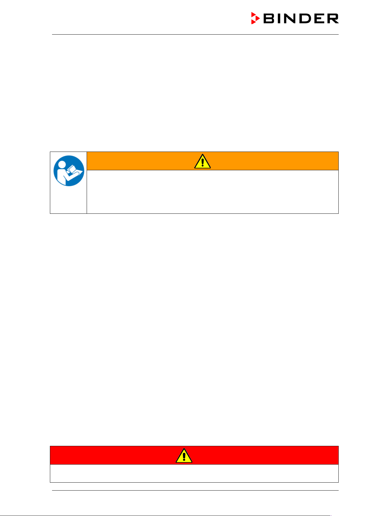
WARNING
Failure to observe the safety instructions.
Serious injuries and chamber damage.
Observe the safety instructions in this operating manual.
Carefully read the complete operating instructions of the VD vacuum drying oven.
1.1 Legal considerations
This operating manual is for informational purposes only. It contains information for installing, start-up,
operation and maintenance of the product. Note: the contents and the product described are subject to
change without notice.
Understanding and observing the instructions in this operating manual are prerequisites for hazard-free
use and safety during operation and maintenance. In no event shall BINDER be held liable for any
damages, direct or incidental arising out of or related to the use of this manual.
This operating manual cannot cover all conceivable applications. If you would like additional information,
or if special problems arise that are not sufficiently addressed in this manual, please ask your dealer or
contact us directly by phone at the number located on page one of this manual
Furthermore, we emphasize that the contents of this operating manual are not part of an earlier or
existing agreement, description, or legal relationship, nor do they modify such a relationship. All
obligations on the part of BINDER derive from the respective purchase contract, which also contains the
entire and exclusively valid statement of warranty administration. The statements in this manual neither
augment nor restrict the contractual warranty provisions.
Have repairs performed only by experts authorized by BINDER. Repaired chambers must comply with
the quality standard specified by BINDER.
1.2 Structure of the safety instructions
In this operating manual, the following safety definitions and symbols indicate dangerous situations
following the harmonization of ISO 3864-2 and ANSI Z535.6.
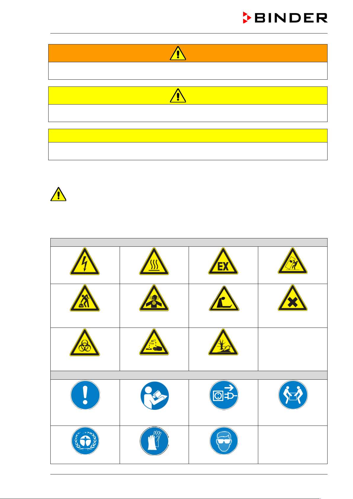
1.2.1 Signal word panel
Depending on the probability of serious consequences, potential dangers are identified with a signal
word, the corresponding safety color, and if appropriate, the safety alert symbol.
DANGER
Indicates an imminently hazardous situation that, if not avoided, will result i n death or serious
(irreversible) injury.
VD (E2.1) 07/2017 page 5/96
Page 6
Warning signs
Electrical hazard
Hot surface
or chemical burns
Mandatory action signs
plug
Wear protective gloves
WARNING
Indicates a potentially hazardous situation which, if not avoided, could result in death or serious
(irreversible) injury.
CAUTION
Indicates a potentially hazardous situation which, if not avoided, may result in m oderat e or m inor
(reversible) injury.
CAUTION
Indicates a potentially hazardous situation, which, if not avoided, may result i n dam age to the product
and/or its functions or to property in its proximity.
1.2.2 Safety alert symbol
Use of the safety alert symbol indicates a risk of injury.
Observe all measures that are marked with the safety alert symbol in order to avoid death or
injury.
1.2.3 Pictograms
Lifting hazard
Biohazard
Inhalation hazard
Risk of corrosion and /
Explosive atmosphere
Suffocation hazard
Pollution Hazard
Stability hazard
Harmful substances
Mandatory regulation
Environment protection
VD (E2.1) 07/2017 page 6/96
Read operating
instructions
Disconnect the power
Wear safety goggles
Lift with several persons
Page 7
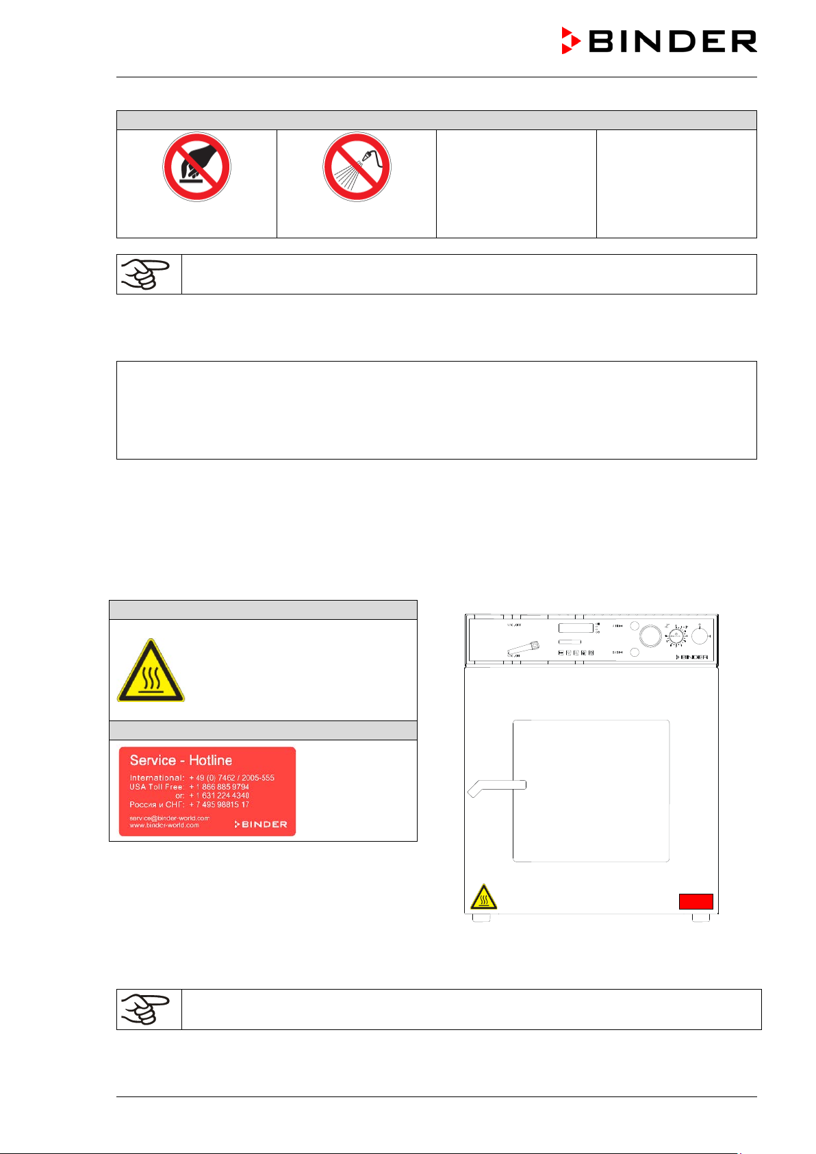
Prohibition signs
water
Pictograms (Warning signs)
Service label
Do NOT touch
Do NOT spray with
Information to be observed in order to ensure optimum function of the product.
1.2.4 Word message panel structure
Type / cause of hazard.
Possible consequences.
∅ Instruction how to avoid the hazard: prohibition
Instruction how to avoid the hazard: mandatory action
Observe all other notes and information not necessarily emphasized in the same way, in order to avoid
disruptions that could result in direct or indirect injury or property damage.
1.3 Localization / position of safety labels on the chamber
The following labels are located on the chamber:
Hot surface
(on the outer chamber door)
Figure 1: Position of labels on the chamber
Keep safety labels complete and legible.
Replace safety labels that are no longer legible. Contact BINDER Service for these replacements.
VD (E2.1) 07/2017 page 7/96
Page 8
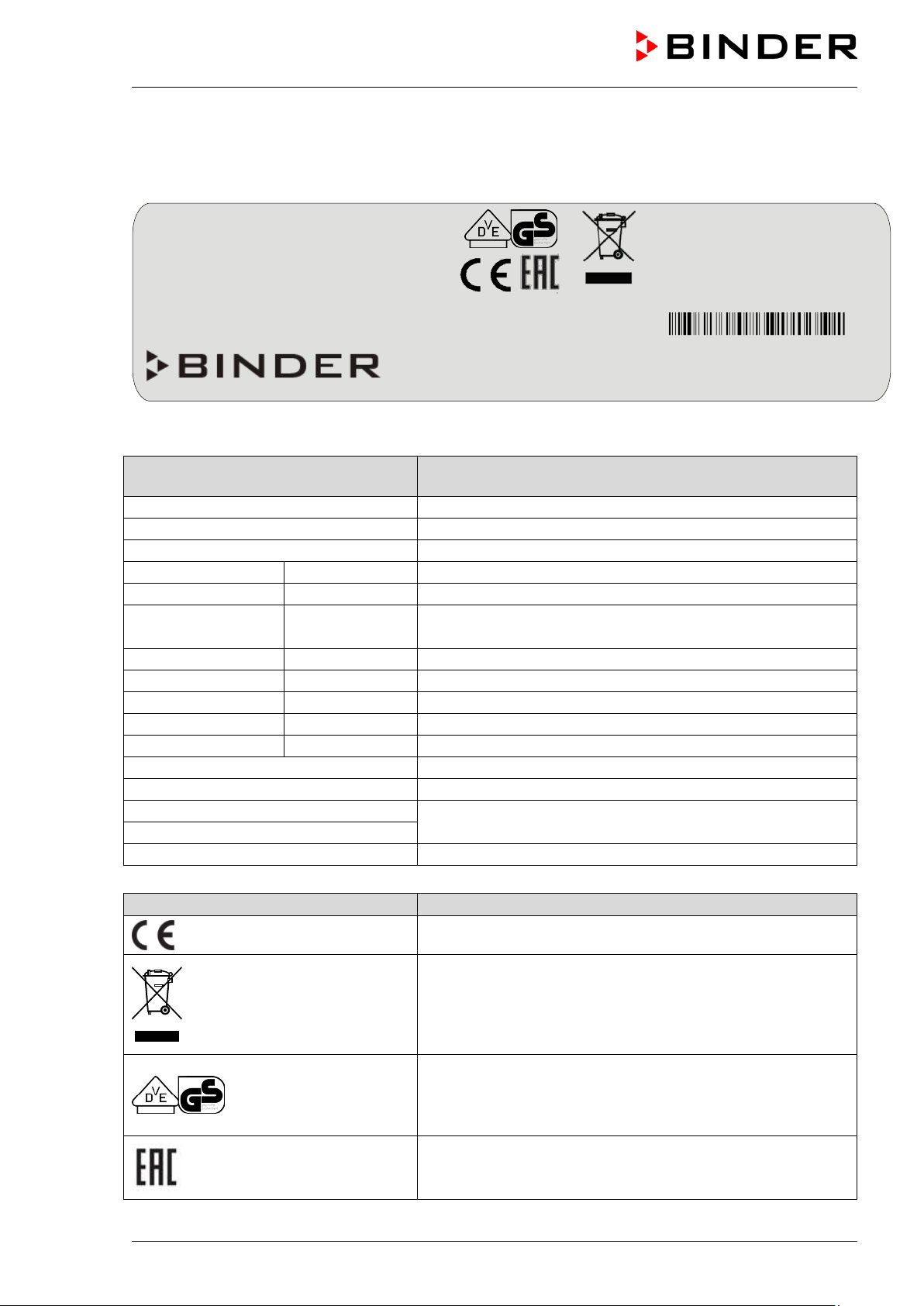
(example)
BINDER
Manufacturer: BINDER GmbH
VD 23
Model designation
Vacuum Drying Oven
Device name
Serial No.
000000000000
Serial no. of the chamber
Built
2017
Year of construction
392 °F
IP protection
20
IP type of protection acc. to standard EN 60529
Temp. safety device
DIN 12880
Temperature safety device acc. to standard DIN 12880:2007
Class
2.0
Class of temperature safety device
Art. No.
9030-0029
Art. no. of the chamber
Project No.
---
Optional: Special application acc. to project no.
0,80 kW
Nominal power
3,5 A
Nominal current
230 V / 50 Hz
Nominal voltage +/- 10%
230 V / 60 Hz
1 N ~
Current type
Symbol on the type plate
Information
Nominal temp.
200 °C
0,80 kW / 3,5 A
392 °F
230 V / 50 Hz
IP protection
20
230 V / 60 Hz
Safety device
DIN 12880
1 N ~
Class
2.0
Art. No.
9030-0029
Built
2017
Vacuum Drying Oven
BINDER GmbH
www.binder-world.com
VD 23
Serial No. 00000000000000
1.4 Type plate
The type plate sticks to the left side of the chamber, bottom right-hand.
Project No.
Figure 2: Type plate (example of VD 23 regular chamber)
Indications of the type plate
Nominal
200 °C
temperature
Im Mittleren Ösch 5
78532 Tuttlingen / Germany
Information
Nominal temperature
E2.1
Made in Germany
VD (E2.1) 07/2017 page 8/96
at the indicated power frequency
CE conformity marking
Electrical and electronic equipment manufactured / placed on
the market in the EC after 13 August 2005 and to be
disposed of in a separate collection according to Directive
2012/19/EU on waste electrical and electronic equipment
(WEEE).
GS mark of conformity of the “VDE Prüf- und
Zertifizierungsinstitut” (Testing and Certification Institute of
the Association for Electrical, Electronic and Information
Technologies
The chamber is certified according to Customs Union
Technical Regulation (CU TR) for the Eurasian Economic
Union (Russia, Belarus, Armenia, Kazakhstan Kyrgyzstan).
Page 9
Symbol on the type plate
Information
®
CAUTION
Do NOT introduce any substance into the oven which is combustible or explosive at
drying oven for drying or heat treatments leading to release of
The chamber is certified by Underwriters Laboratories Inc.
according to the following standards:
(VD-UL only)
UL 61010A-1, UL 61010A-2-10
CSA C22.2 No. 1010.1-92, CSA C22.2 No. 1010.2.010-94
1.5 General safety instructions on installing and operating the chamber
With regard to operating the chamber and to the installation location, please observe the DGUV
guidelines 213-850 on safe working in laboratories (formerly BGI/GUV-I 850-0, BGR/GUV-R 120 or ZH
1/119, issued by the employers’ liability insurance association) (for Germany).
BINDER GmbH is only responsible for the safety features of the chamber provided skilled electricians or
qualified personnel authorized by BINDER perform all maintenance and repair, and if components
relating to chamber safety are replaced in the event of failure with original spare parts.
To operate the chamber, use only original BINDER accessories or accessories from third-party suppliers
authorized by BINDER. The user is responsible for any risk caused by using unauthorized accessories.
Danger of overheating.
Damage to the chamber.
∅ Do NOT install the oven in unventilated recesses.
Ensure sufficient ventilation for dispersal of the heat.
Do not operate the chamber in hazardous locations.
DANGER
Explosion hazard.
Danger of death.
∅ Do NOT operate the chamber in potentially explosive areas.
KEEP explosive dust or air-solvent mixtures AWAY from the chamber.
The chamber is regularly equipped with a large-surface area safety valve. The window, manufactured in
toughened safety glass, is elastic-mounted and serves as a safety valve in the event of explosion. The
additional plastic panel provides splinter protection.
DANGER
Explosion hazard.
Danger of death.
∅
working temperature.
∅ NO explosive dust or air-solvent mixture in the inner chamber.
∅ Do NOT use the vacuum
combustible vapors able to form an explosive mixture with air.
VD (E2.1) 07/2017 page 9/96
Page 10
Any solvent contained in the charging material must not be explosive or inflammable. I.e., irrespective of
the solvent concentration in the steam room, NO explosive mixture with air must form. The drying
temperature must lie below the flash point or below the sublimation point of the charging material.
Familiarize yourself with the physical and chemical properties of the charging material, as well as the
contained moisture constituent and its behavior with the addition of heat energy and changes in pressure.
Familiarize yourself with any potential health risks caused by the charging material, the contained
moisture constituent or by reaction products that may arise during the drying process. Take adequate
measures to exclude such risks prior to putting the chamber into operation.
DANGER
Electrical hazard.
Danger of death.
∅ The oven must NOT become wet during operation or maintenance.
The chambers were produced in accordance with the relevant VDE regulations and were routinely tested
in accordance to VDE 0411-1 (IEC 61010-1).
During and shortly after operation, the temperature of the inner surfaces almost equals the set-point.
CAUTION
The inner chamber will become hot during operation.
Danger of burning.
∅ Do NOT touch the inner surfaces or the charging material during operation.
In the case of operation with inert gas, the chamber is supplied with an oxygen-displacing gas (e.g. N2).
The gas emerging from the system must therefore be removed from the installation area by means of a
suitable extraction system (see technical ventilation measures in the DGUV guidelines 213-850 on safe
working in laboratories (formerly BGI/GUV-I 850-0, BGR/GUV-R 120 or ZH 1/119, issued by the
employers’ liability insurance association) (for Germany).
With use of a vacuum system or a vacuum pump, observe the permitted gas inlet
temperature. Observe the safety instructions of the pump manufacturer.
VD (E2.1) 07/2017 page 10/96
Page 11
plosive at working temperature into
1.6 Intended use
The VD vacuum drying ovens are suitable for drying and heat treatment of solid or pulverized charging
material, as well as bulk material, using the supply of heat under vacuum. The solvent content must not
be explosive or flammable. A mixture of any component of the charging material with air must NOT be
explosive. The drying temperature must lie below the flash point or below the sublimation point of the
charging material. Any component of the charging material must NOT be able to release toxic gases.
Other applications are not approved.
The chambers are not classified as medical devices as defined by the Medical Device Directive
93/42/EEC.
Observing the instructions in this operating manual and conducting regular maintenance work
(chap. 17) is part of the intended use.
The charging material shall not contain any corrosive ingredients that may damage the
machine components made of stainless steel and aluminum. Such ingredients include in
particular acids and halides. Any corrosive damage caused by such ingredients is excluded
from liability by BINDER GmbH.
DANGER
Explosion or implosion hazard.
Danger of poisoning.
Danger of death.
∅ Do NOT introduce any substance combustible or ex
the chamber, in particular no energy sources such as batteries or lithium-ion batteries
∅ NO explosive dust or air-solvent mixture in the inner chamber.
∅ Do NOT introduce any substance which could lead to release of toxic gases.
In case of foreseeable use of the chamber there is no risk for the user through the integration of the
chamber into systems or by special environmental or operating conditions in the sense of EN 610101:2010. For this, the intended use of the chamber and all its connections must be observed.
VD (E2.1) 07/2017 page 11/96
Page 12

2. Description of the equipment
Vacuum drying is used for special drying problems, for which conventional drying methods cannot offer a
solution due to physical limitations.
All functions of the multifunctional program control can be set simply and conveniently via the easy to
understand function keypad of the RD3 temperature program controller. This controller is equipped with
touch function keys and a digital display and permits exact temperature setting and programming
temperature cycles. The VD provides almost unlimited possibilities of adapting to individual customer
requirements based upon extensive programming options and on the week program timer and real time
clock of the controller.
The inner chamber is made of especially corrosion resistant stainless steel V4A (German material no.
1.4404 2B, US equivalent AISI 316L) micro-polished. The rack holder and all of the chamber's vacuum
connections and valves are made of especially corrosion resistant stainless steel V4A (German material
no. 1.4571, US equivalent AISI 316Ti). The housing is RAL 7035 powder-coated. All corners and edges
are also completely coated. When operating the chamber at temperatures above 150 °C / 302 °F, the
impact of the oxygen in the air may cause discoloration of the metallic surfaces (yellowish-brown or blue)
by natural oxidation processes. These colorations are harmless and will in no way impair the function or
quality of the chamber.
The chambers are jacket-heated. The APT.line™ preheating c hamber technique ensures a completely
homogeneous jacket temperature, ensuring uniform heat transfer into the inner chamber. The low-loss
heat transfer to the material uses the patented aluminum vacuum expansion racks (or optionally available
in stainless steel). The elastic-mounted safety glass window reliably compensates any overpressure or
explosions that may occur. The additional polycarbonate panel ensures proven and effective splinter
protection in the event of an implosion.
All VD chambers provide an inert gas connection and a measuring connection serving to connect a
vacuum controller or a measuring access port.
The chambers are equipped as standard with a large-surface safety valve. The toughened safety glass
window is elastic-mounted and in the event of explosion serves as a safety valve. The additional plastic
panel provides splinter protection.
The chambers are equipped with a serial interface RS 422 for computer communication, e.g. via the
communication software APT-COM™ 3 DataControlSystem (option, chap.16.8). For further options, see
chap. 20.3.
All installable items, such as racks and rack holders, can be easily removed. The completely smooth
inner chamber with its rounded corners and internally welded seams is easy to clean.
The minimum working temperature of the vacuum drying oven is approx. 15 °C / 27 °F above room
temperature. The maximum temperature is 200 °C / 392 °F.
3
Vacuum pumps with a suction capacity of 1 m
The permissible end vacuum is 10
-2
mbar / 0.0003 inHg.
/h to 30 m3/h are suitable for the VD vacuum drying oven.
VD (E2.1) 07/2017 page 12/96
Page 13

(A)
(B)
(C)
(D)
(E)
2.1 Chamber overview
Figure 3: VD 23 with option vacuum module and chemical membrane pump
(A) Control panel and instrument box
(B) Chamber door
(C) Elastic-mounted safety glass window
(D) Vacuum module (option)
(E) Chemical membrane pump (option)
VD (E2.1) 07/2017 page 13/96
Page 14
VAC.OFF
VAC.ON
AIR
GAS
AIR/GAS
VAC.OFF
VAC.ON
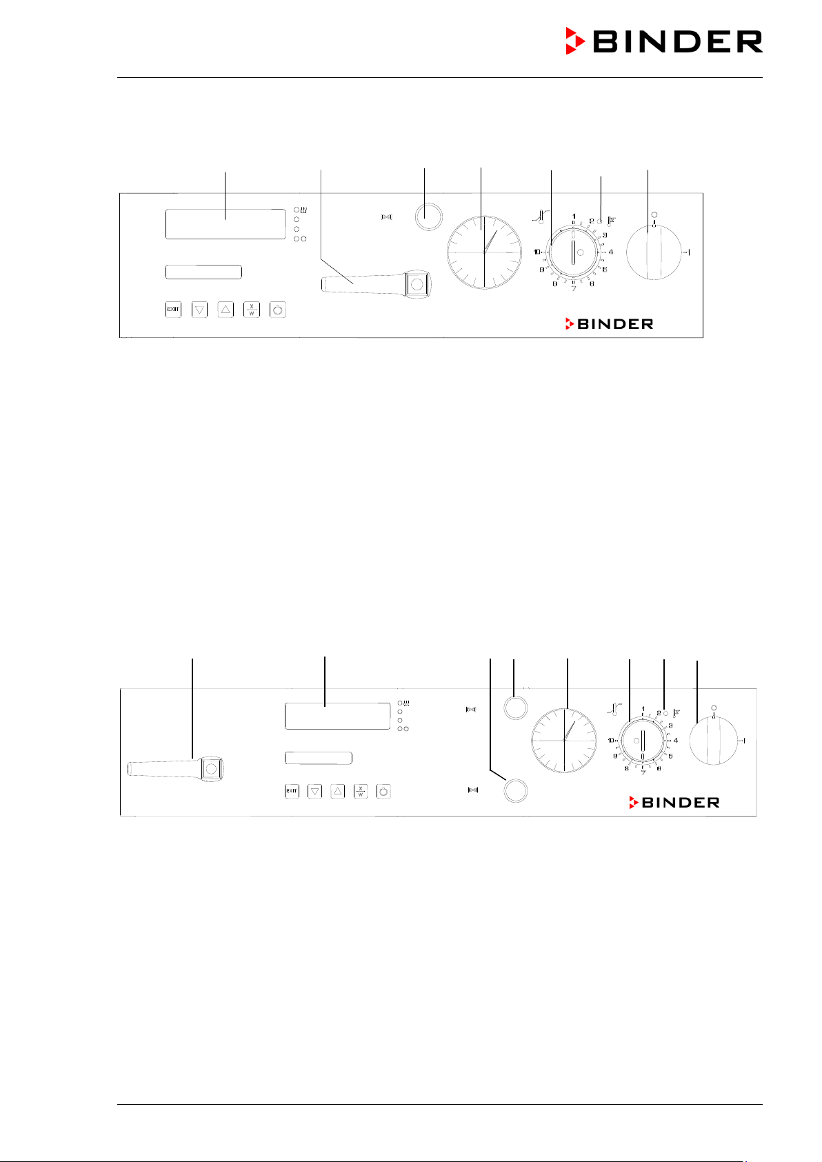
2.2 VD 23 control panel
(7) (8) (4) (3) (2) (2 a) (1)
Figure 4: VD 23 control panel
(1) On/off switch (main power switch)
(2) Temperature safety device class 2
(2a) Red alarm lamp of the safety device class 2
(3) Manometer (pressure reading)
(4) Aeration valve (inert gas or ambient air)
(7) Program controller RD3
(8) Vacuum shut-off valve
2.3 VD 53 / 115 control panel
(8) (7) (6) (5) (3) (2) (2a ) (1 )
Figure 5: VD 53/115 control panel
(1) On/off switch (main power switch)
(2) Temperature safety device class 2
(2a) Red alarm lamp of the safety device cla ss 2
(3) Manometer (pressure reading)
(5) Aeration valve (ambient air)
(6) Fine dosing valve (inert gas)
(7) Program controller RD3
(8) Vacuum shut-off valve
VD (E2.1) 07/2017 page 14/96
Page 15
(17)
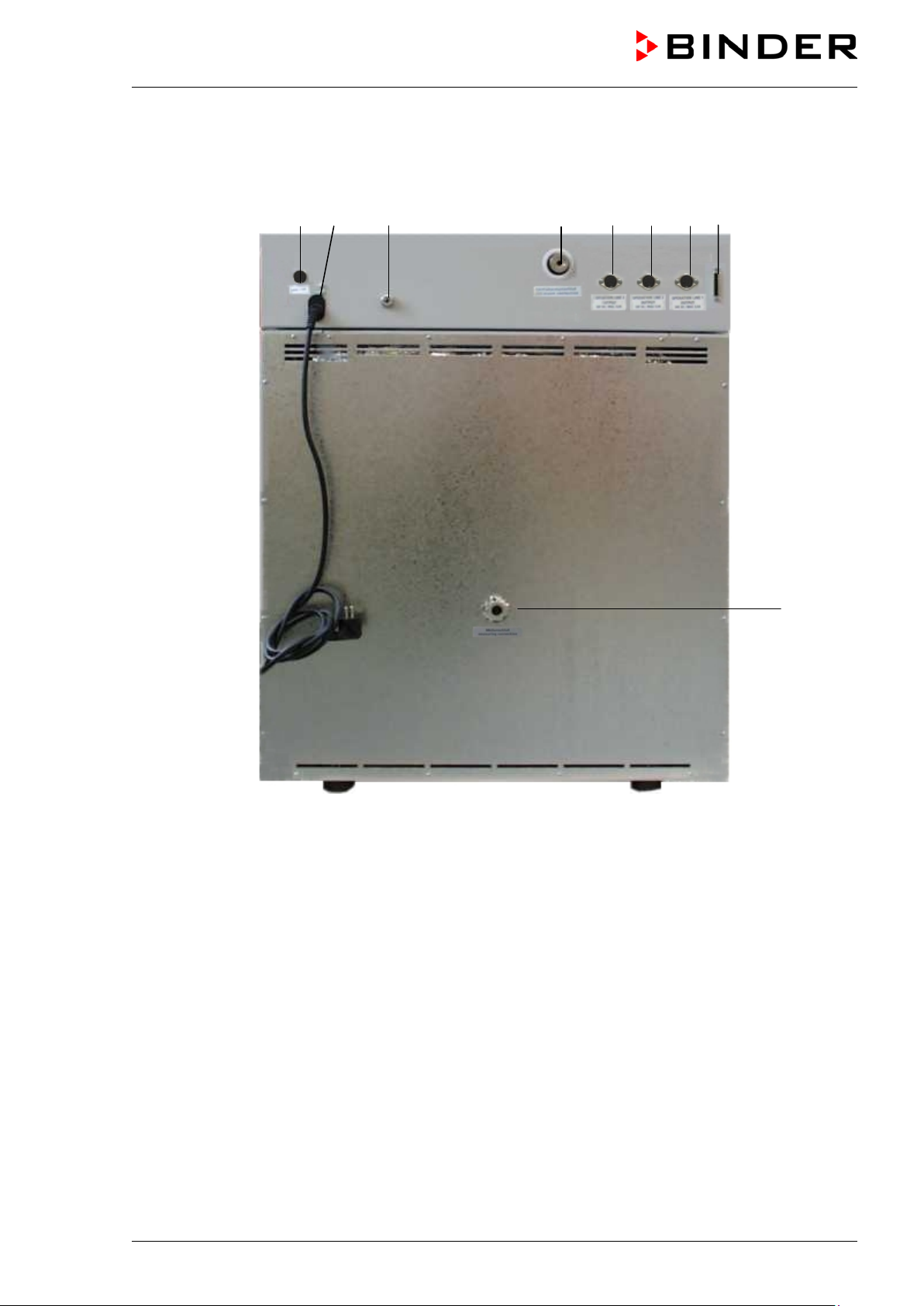
2.4 Connections at the rear of the chamber
(10) (11) (12) (13) (14) (15) (16) (9)
Figure 6: Rear of VD
(9) RS 422 serial interface for computer communication
(10) Miniature fuse
(11) Power connection line
(12) Inert gas connection, adapter with hose olive ∅ 8 mm / 0.31 in
(VD23: also fresh air inlet)
(13) Vacuum connection with small flange DN16
(14) DIN socket (option) for option “object temperature display”
(15) DIN socket (operation line 2) (option) for option “program controlled venting”
(16) DIN socket (operation line 1) (option) for option “vacuum module with pump”
(17) Measuring connection with small flange DN16
VD (E2.1) 07/2017 page 15/96
Page 16
the door or the lower
of 4
3. Completeness of delivery, transportation, storage, and
installation
3.1 Unpacking, and checking equipment and completeness of delivery
After unpac king, please check the chamber and its optional accessories, if any, based on the delivery
receipt for completeness and for transportation damage. Inform the carrier immediately if transportation
damage has occurred.
The final tests of the manufacturer may have caused traces of the shelves on the inner surfaces. This has
no impact on the function and performance of the chamber.
Please remove any transportation protection devices and adhesives in/on the chamber and on the doors
and remove the operating manuals and accessory equipment.
CAUTION
Sliding or tilting of the chamber.
Damage to the chamber.
Risk of injury by lifting heavy loads.
∅ Do NOT lift or transport the chamber using the door handle,
housing.
Lift chambers size 23 and 53 from the pallet at the four lower corners with the aid
people.
Lift chambers size 115 from the pallet with the aid of 6 people.
If you need to return the chamber, please use the original packing and observe the guidelines for safe
lifting and transportation (chap. 3.2).
For disposal of the transport packing, see chap. 18.1.
If you ordered the option “vacuum module with chemical membrane pump”, the pump will be delivered in
a separate box and must be fitted into the module and connected at the place of installation (see chap.
16.3 and 16.4).
Note on second-hand chambers (Ex-Demo-Units):
Second-hand chambers are chambers that were used for a short time for tests or exhibitions. They are
thoroughly tested before resale. BINDER ensures that the chamber is technically sound and will work
flawlessly.
Second-hand chambers are marked with a sticker on the chamber door. Please remove the sticker
before commissioning the chamber.
VD (E2.1) 07/2017 page 16/96
Page 17
3.2 Guidelines for safe lifting and transportation
After operation, please observe the guidelines for temporarily decommissioning the chamber (chap.
18.2).
CAUTION
Sliding or tilting of the chamber.
Damage to the chamber.
Risk of injury by lifting heavy loads.
Transport the chamber in its original packaging only.
For moving or shipping, secure the oven with transport straps.
∅ Do NOT lift or transport the chamber using the door, the handle, or the lower housing.
Lift chambers size 23 and 53 at the four lower corners with the aid of 4 people.
Lift chambers size 115 with the aid of 6 people.
• Permissible ambient temperature range during transport: -10 °C / 14°F to +60 °C / 140°F.
You can order transport packing for moving or shipping purposes from BINDER Service.
3.3 Storage
Intermediate storage of the chamber in a closed and dry room. Observe the guidelines for temporary
decommissioning (chap. 18.2).
• Permissible ambient temperature range during storage: -10 °C / 14°F to +60 °C / 140°F.
• Permissible ambient humidity: max. 70 % r.H., non-condensing
When after storage in a cold location you transfer the chamber to its warmer installation site,
condensation may form. Before start-up, wait at least one hour until the chamber has attained ambient
temperature and is completely dry.
3.4 Location of installation and ambient conditions
Set up the VD vacuum drying oven on a flat, even, and non-flammable surface, free from vibration, in a
well-ventilated, dry location. Align it using a spirit level. The site of installation must be capable of
supporting the chamber’s weight (see technical data, chap. 20.2). The chambers are designed for setting
up inside a building (indoor use).
CAUTION
Danger of overheating.
Damage to the chamber.
∅ Do NOT set up chambers in non-ventilated recesses.
Ensure sufficient ventilation for dispersal of the heat.
• Permissible ambient temperature range during operation: +18 °C / 64°F to +32 °C / 90°F.
The ambient temperature should not be substantially higher than the indicated ambient
temperature of +25 °C / 77°F to which the specified technical data relate. Deviations from the
indicated data are possible for other ambient conditions.
• Permissible ambient humidity: 70 % r.H. max., non-condensing.
• Installation height: max. 2000 m / 6562 ft above sea level.
VD (E2.1) 07/2017 page 17/96
Page 18
CAUTION
When decommissioning the vacuum drying oven, shut off the inert gas supply: Close
When placing several chambers of the same size side by side, maintain a minimum distance of 250 mm /
9.8 in between each chamber. Wall distances: rear 100 mm / 3.9 in, sides 135 mm / 5.3 in. Spacing
above and behind the chamber of at least 100 mm / 3.9 in must also be maintained.
Danger by stacking.
Damage to the chambers.
∅ Do NOT place vacuum drying ovens on top of each other.
To completely separate the chamber from the power supply, you must disconnect the power plug. Install
the chamber in a way that the power plug is easily accessible and can be easily pulled in case of danger.
For the user there is no risk of temporary overvoltages in the sense of EN 61010-1:2010.
Do not install or operate the vacuum drying oven VD in potentially explosive areas.
DANGER
Explosion hazard.
Danger of death.
∅ Do NOT operate the chamber in potentially explosive areas.
KEEP explosive dust or air-solvent mixtures AWAY from the vicinity of the chamber.
The maximum permissible ambient temperature of the vacuum pumps delivered by BINDER is 40 °C /
104°F.
Notes when using inert gas:
When operating the VD vacuum drying oven with inert gas, correctly follow the technical ventilation
measures, as described in the DGUV guidelines 213-850 on safe working in laboratories (formerly
BGI/GUV-I 850-0, BGR/GUV-R 120 or ZH 1/119, issued by the employers’ liability insurance association)
(for Germany).
For operation with inert gas, the chamber is supplied with an oxygen-displacing gas, e.g. N
in high concentrations are hazardous to health. They are colorless and almost odorless and therefore
practically imperceptible. Inhalation of inert gases can cause drowsiness up to respiratory arrest. When
content of the air decreases below 18%, there is risk of death from lack of oxygen. Any gas that
the O
2
might escape has to be led out via good room ventilation or a suitable exhaust system.
. Inert gases
2
WARNING
High concentration of inert gas.
Risk of death by suffocation.
∅ Do NOT set up chambers in non-ventilated recesses.
Ensure technical ventilation measures.
Respect the relevant regulations for handling these gases.
valves (4) or (6).
VD (E2.1) 07/2017 page 18/96
Page 19
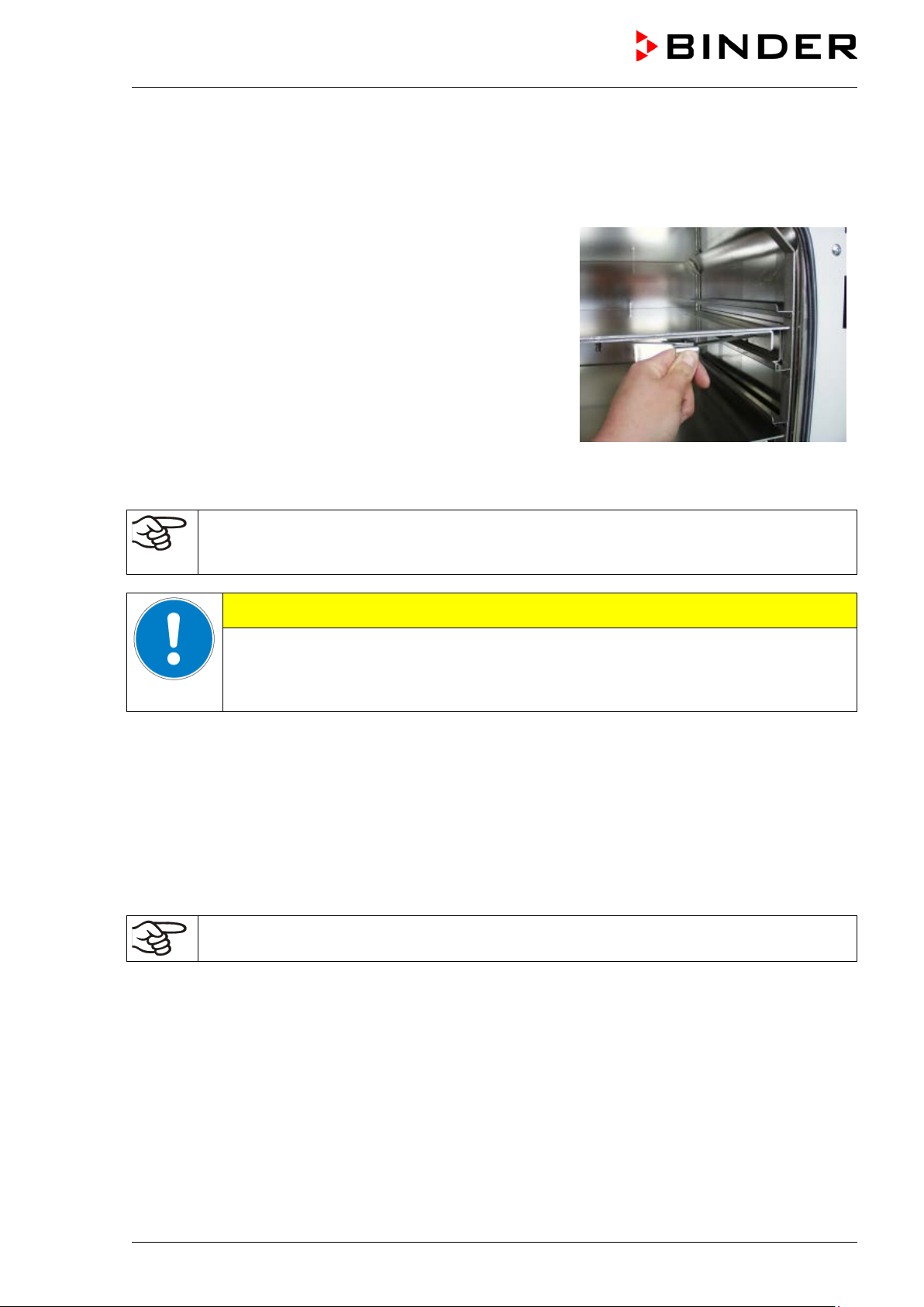
The low-loss heat transfer to the material occurs via the
CAUTION
4. Installation and connections
4.1 Vacuum expansion racks
patented aluminum vacuum expansion racks (also available in
stainless steel as an option). The strong tension causes the
racks to fit tightly against the interior wall and their largesurface contact area ensures rapid and effective heat transfer.
The removable rack holders allow for easy positioning.
You can also remove the expansion racks for easy cleaning.
Do not remove them too often in order to prevent wear.
Figure 7: Using the expansion racks
• Pushing the locking lever: The expansion rack is released and can be removed.
• Pulling the locking lever: The expansion rack is pressed against the inner chamber walls.
Following each new tightening of an expansion rack, check that the lateral parts of the rack fit
closely over their whole surface to the inner chamber wall. This is necessary in order to
ensure the specified temperature exactitude.
Invalid calibration.
∅ Do NOT change between aluminum and stainless steel racks
Use the delivered expansion racks only
4.2 Vacuum connection
Always connect the VD vacuum drying oven to a vacuum pump or to a domestic vacuum system. For this
purpose, the vacuum connection (13) with small flange DN16 must be connected to the back of the
chamber at the top with the vacuum pump or domestic vacuum system via a vacuum suction hose. For
connecting to the chamber, BINDER recommends the connection kit VD, Art. no. 8012-0146.
With the option “stainless steel tubing” between the vacuum oven and vacuum module, the vacuum
connection is already located inside the vacuum module.
Vacuum pumps with a suction capacity of 1-30 m³/h are suitable for the VD vacuum drying
oven. Permissible end vacuum: 10
4.3 Inert gas connection
When operating the VD vacuum drying oven with inert gas, correctly follow the technical ventilation
measures, as described in the DGUV guidelines 213-850 on safe working in laboratories (formerly
BGI/GUV-I 850-0, BGR/GUV-R 120 or ZH 1/119, issued by the employers’ liability insurance association)
(for Germany).
Connect the inert gas supply to the inert gas connection (adapter with hose olive diameter 8 mm / 0.31 in)
via a pressure reducer. Screw the enclosed adapter with hose olive on the thread (12) at the chamber
rear. Set the pressure reducer to a pressure slightly above ambient pressure. Ensure that the pressure
reducer will certainly open. Do not alter this setting in order to avoid perturbation inside the oven and
release of big quantities of inert gas after flooding the VD.
VD (E2.1) 07/2017 page 19/96
-2
mbar / 0.0003 inHg.
Page 20
When decommissioning the vacuum drying oven, shut off the inert gas supply: Close
VD 23
VD 115
VD 23-UL
VD 53-UL
CAUTION
Inert gases in high concentrations are hazardous to health. They are colorless and almost odorless and
therefore practically imperceptible. Inhalation of inert gases can cause drowsiness up to respiratory
arrest. When the O
Any gas that might escape has to be led out via good room ventilation or a suitable exhaust system.
content of the air decreases below 18%, there is risk of death from lack of oxygen.
2
WARNING
High concentration of inert gas.
Risk of death by suffocation.
∅ Do NOT set up chambers in non-ventilated recesses.
Ensure technical ventilation measures.
Respect the relevant regulations for handling these gases.
valves (4) or (6).
4.4 Electrical connection
The chambers are supplied ready for connection. They come with a fixed power connection cable of at
least 1800 mm / 70.87 in in length.
Model Power plug
VD 53
VD 115-UL NEMA 5-20P 115 V at 60 Hz 1N~ 20 A
• The domestic socket must also provide a protective conductor. Make sure that the connection of the
protective conductor of the domestic installations to the chamber’s protective conductor meets the
latest technology. The protective conductors of the socket and plug must be compatible!
• Prior to connection and start-up, check the power supply voltage. Compare the values to the specified
data located on the chamber’s type plate (chamber front behind the door, bottom left-hand, see chap.
1.4).
• When connecting, please observe the regulations specified by the local electricity supply company
and as well as the VDE directives (for Germany). We recommend the use of a residual current circuit
breaker.
• Pollution degree (acc. to IEC 61010-1): 2
• Over-voltage category (acc. to IEC 61010-1): II
Shockproof plug
NEMA 5-15P 115 V at 60 Hz 1N~ 12,5 A
Nominal voltage ± 10% at the
indicated power frequency
230 V at 50 Hz
230 V at 60 Hz
Current
type
1N~ 10 A
Chamber
fuse
Danger of incorrect power supply voltage.
Damage to the equipment.
Check the power supply voltage before connection and start-up.
Compare the power supply voltage with the data indicated on the type plate.
See also electrical data (chap. 20.2).
To completely separate the chamber from the power supply, you must disconnect the power
plug. Install the chamber in a way that the power plug is easily accessible and can be easily
pulled in case of danger.
VD (E2.1) 07/2017 page 20/96
Page 21
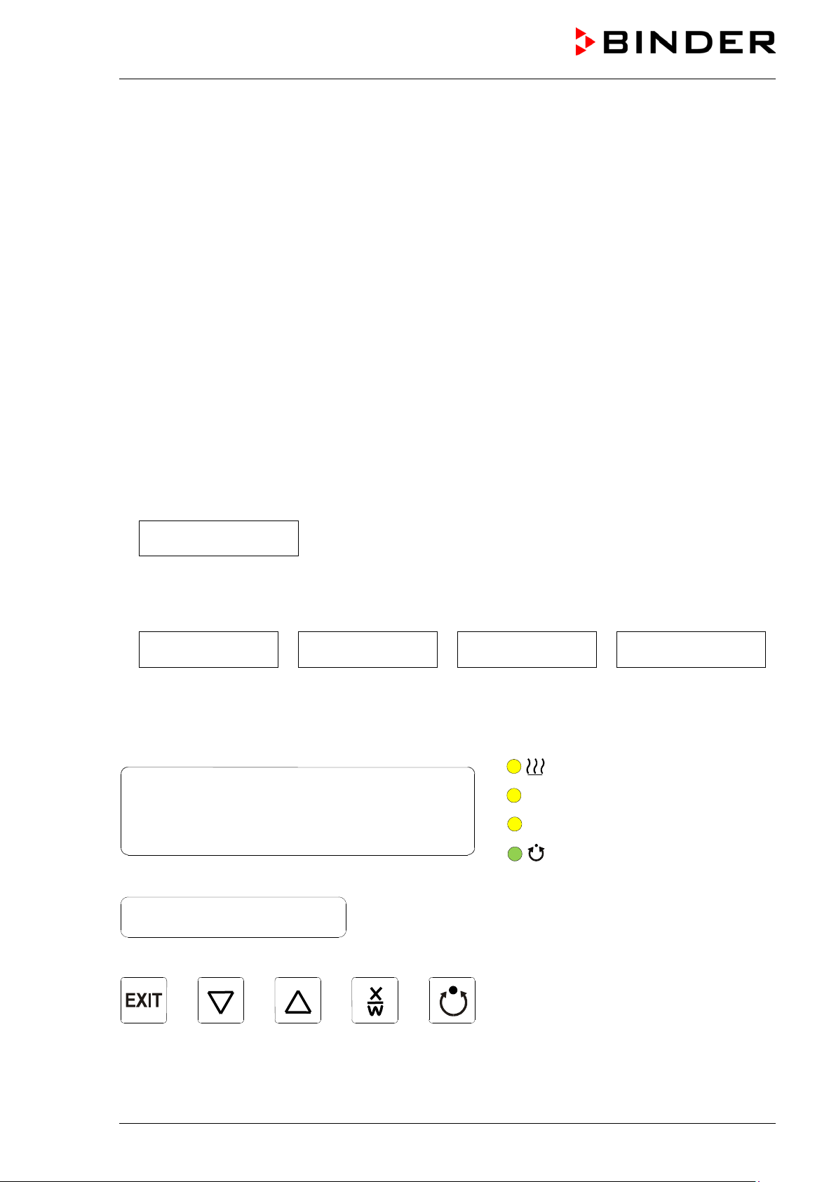
Display 1
Display 2
5. Start up
After connecting the supply lines (chap 4), turn on the chamber via the main power switch (1):
• Position 0: Oven without function
• Position I: Oven operating
Warming chambers may release odors in the first few days after commissioning. This is not a quality
defect. To reduce odors quickly we recommend heating up the chamber to its nominal temperature for
one day and in a well-ventilated location.
5.1 Settings at the RD3 program controller
After turning on the chamber at the main power switch (1), the controller is in Normal Display / Fixed
value operation mode.
Depending on the temperature value entered before, LED (7a) is lit if the heating is active, or no LED is lit
if the actual temperature is equal to or above the set-point.
In Display 1 of the controller the actual temperature value is displayed.
• With inactive week program timer:
In Display 2 of the controller the actual date and time are displayed. Example:
15.05.06 13:52
• With active week program timer:
In Display 2 of the controller the actual date and time and the states of the week program timer
channels are displayed. Examples:
15.05.06 13:52 - - 15.05.06 13:52 - �
Channel 1 Off,
Channel 2: Off
Channel 1: O ff,
Channel 2: On
15.05.06 13:52 � -
Channel 1: On,
Channel 2: Off
(7a) LED Heating active
(7b) LED Operation line 1 ON
(7c) LED Operation line 2 ON
(7d)
LED lit: program operation
LED flashing: exceeding of the
tolerance limits in “Fixed value
entry mode” or in “Program
operation”. In program operation:
program interruption.
15.05.06 13:52 � �
Channel 1 On,
Channel 2: On
Figure 8: RD3 program controller
VD (E2.1) 07/2017 page 21/96
Page 22

The program controller RD3 permits programming temperature cycles.
You can enter two programs with up to 10 sections each or one program with up to 20 sections (setting in
the user level, chap. 10).
When changing from 2 programs to 1 program or vice-versa, existing programs are deleted.
The maximum length of an individual program section can be set to either 99 h 59 min or to 999 h 59 min
(setting in the user level, chap. 10). This setting is then valid for all program sections.
Programming can be done directly through the keypad of the controller or graphically through the
software APT-COM™ 3 DataControlSystem (option, chap. 16.8) specially developed by BINDER.
5.2 General indications on the RD3 program controller
The program controller RD3 offers several functional levels:
Normal Display / Fixed value operation:
• Display of the temperature actual value (display 1) and of the actual date and time (display 2).
• The oven is in fixed value operating mode, equilibrating to the entered set-points.
Fixed value entry mode (chap. 6)
• Entry of the temperature set-point for fixed value operating mode
• Entry of temperature set-points 1 and 2 for week program operation
Program editor (chap. 8)
• You can enter two programs with up to 10 sections each or one program with up to 20 sections
(selection in the user level, chap. 10). Entry of temperature set-points in all program sections (chap.
8.1).
• Deleting a program section (chap. 8.4)
Program start level (chap. 9)
• Selection of an entered program
• Entry of settings affecting the program course, as “start delay time” or “number of program cycles”
• Program start
Week program editor (chap.7)
• Setting the shift points
User level (chap. 10)
• User specific controller settings
• Setting the real time clock
VD (E2.1) 07/2017 page 22/96
Page 23
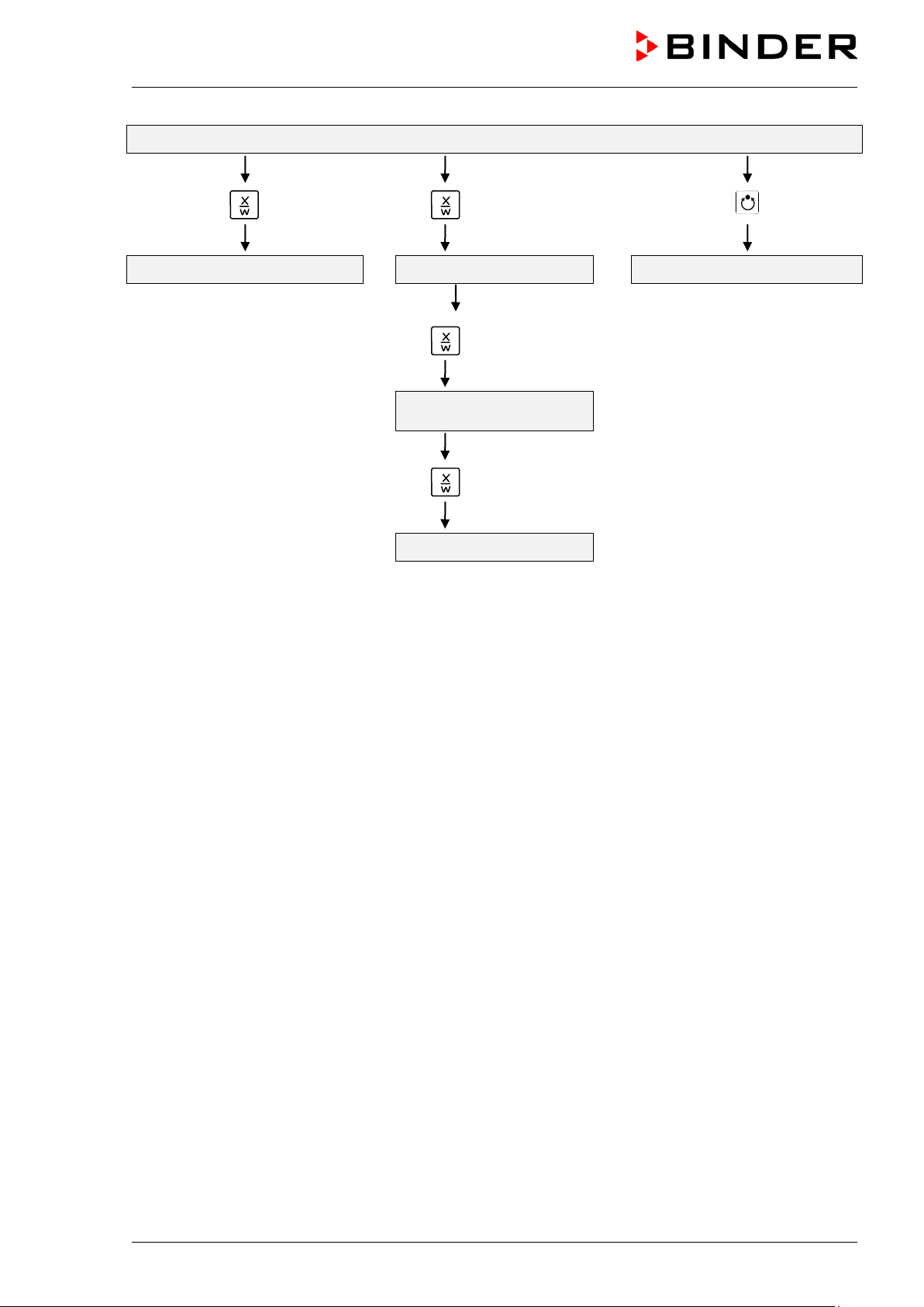
Menu visible only if week program
timer is activated in the user level
Normal Display / Fixed value operation
5 seconds
Fixed value entry mode Program editor Program start level
Week program editor
5 seconds
5 seconds
User level
If no button is touched during more than 120 sec., the controller returns from the current level to Normal
Display.
VD (E2.1) 07/2017 page 23/96
Page 24
Display 1 shows
e.g. 39.8 C
(actual temperature value)
channel 1: Off,
channel 2: Off, visible only if week program timer is activated
in the user level, chap. 10)
Display 1 shows
e.g. 40.0 C
(actual temperature set-point 1)
Display 2 shows
SP1 TEMPERATURE
(variable: temperature in °C)
C
in the user level, chap. 10)
Display 2 shows
SP2 TEMPERATURE
(variable: temperature in °C)
Display 1 shows
e.g. 000
(actual switching state of operation lines)
Display 2 shows
OPERATION LINE
(variable: switching state of operation lines)
6. Fixed value entry mode
If you do not want to use the week program timer, deactivate it (factory setting, setting in the
user level, chap. 10) before entering any set-points. Any setting of the operation l ines in fixed
value entry mode is ineffective with active week program timer.
Basic entry principle: Access the individual parameters with button X/W. Enter the value with the arrow
keys. A value flashing once after 2 seconds indicates that it has been applied by the controller.
Normal Display
Display 2 shows e.g. 15.05.06 13:52 - - (actual date and time)
(actual switching state of week program timer
Press key
Enter temperature set-point in °C using
arrow keys
Press key
Display 1 shows e.g. 50.0
(actual temperature set-point 2)
Enter temperature set-point in °C using
arrow keys
Press key
Enter switching state of operation lines using
arrow keys
Press key
Value is shown in display 1.
(visible only if week program timer is activated
Value is shown in display 1.
(see chap. 15, switching outputs via operation
lines)
If no button is pressed within more than 120 sec, or if the EXIT button is pressed, the controller changes
to Normal Display.
When changing the set-point, check the setting of the safety device (chap. 12).
The values entered in fixed-value entry mode remain valid after program run-off and are then
equilibrated.
If the week program timer is active, depending on the running week program another set-point (SP2) may
be targeted. Temperatures too high or too low for the introduced solvent quantity can occur. Deactivate
the week program timer if you do not use it (default setting, setting i n the User level, chap. 10).
VD (E2.1) 07/2017 page 24/96
Page 25
Display 1 shows
e.g. 39.8 C
(actual temperature value)
Display 2 shows
(actual date and time, actual state of week program timer
channel 1: Off, channel 2: Off)
Display 1 shows
e.g. 0000
Display 2 shows
PROGRAM EDITOR
(you are in the program editor)
Display 1 shows
0000
Menu visible only if week program timer is activated
in the user level (chap. 10)
Display 2 shows
WEEK PROG. EDITOR
(you are in the week program editor)
Display 1 shows
0000
Display 2 shows
UserCod?
0000
(enter user code, display flashes)
Display 1 shows
0000
(actual selection: Monday)
Select the day of the week (Monday up to
CAUTION
Too high or too low temperature.
Damage to the charging material.
Deactivate the week program timer if you do not use it.
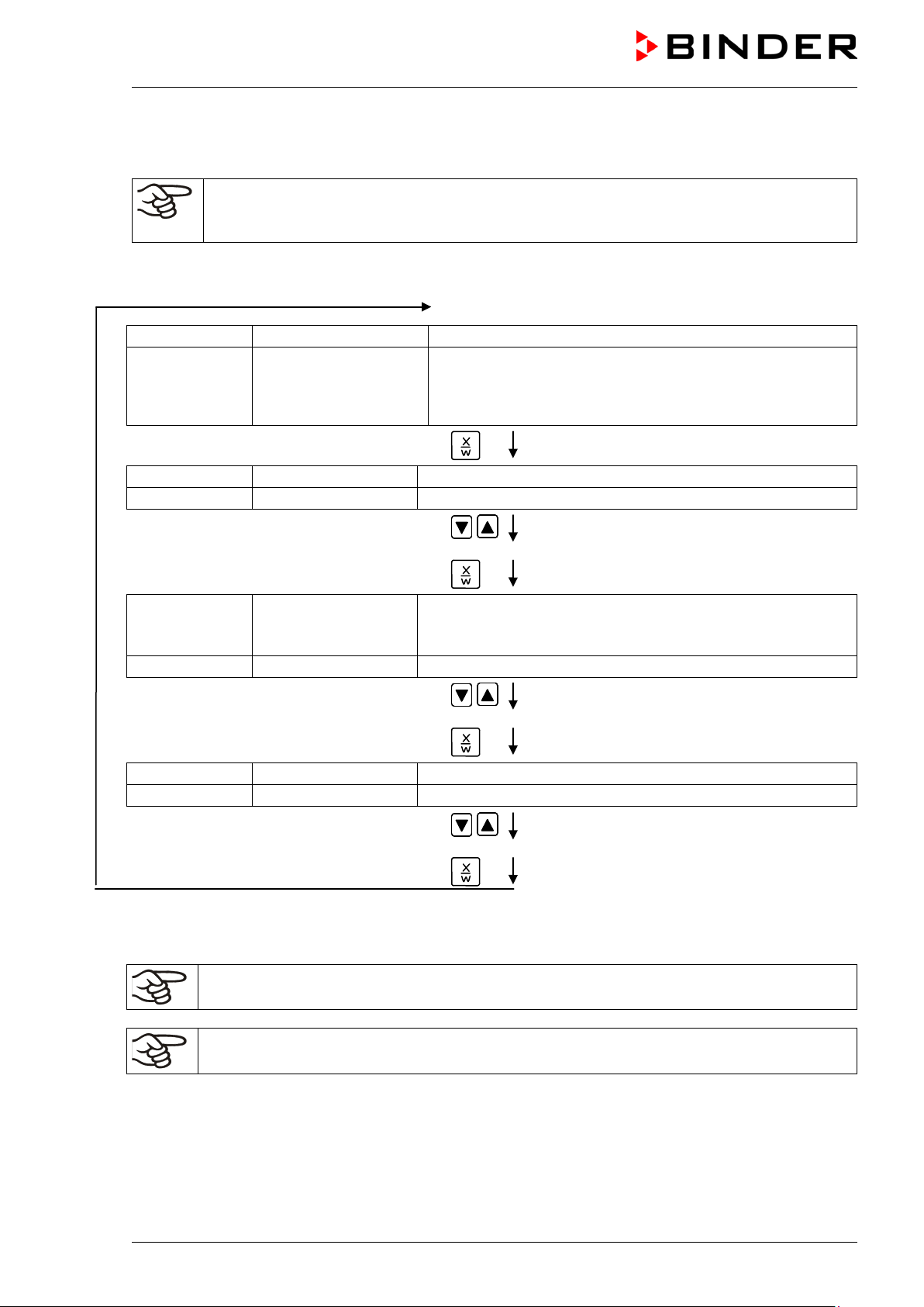
7. Week program editor
The Week program editor permits defining up to 4 shift point for each week day. A shift point defines a
moment and the switching state ON or OFF of the channels that become active in this instance.
Channel function:
• Channel 1 On = Set-point SP2 is equilibrated.
• Channel 1 Off = Set-point SP1 is equilibrated
• Channel 2 = reserve
The week program timer is initially set to inactive (factory setting). Therefore, you need to
activate the week program timer in the user level (chap. 10).
Normal Display
e.g. 15.05.06 13:52 - -
Press down key
Press down key
Press program key
Enter the user code using arrow keys
Automatically forward after 2 sec
for 5 sec
for 5 sec
e.g. 0001 (basic setting, adjustable in the
user level, chap. 10).
Value is shown in both displays.
Display 2 shows
VD (E2.1) 07/2017 page 25/96
Monday
Sunday) with key
Press program key
(selection of day of the week)
Day of the week is shown in display 2.
Page 26
Display 1 shows
0000
Display 2 shows
Shiftpt.
(no function)
Display 1 shows
0000
Display 2 shows
(selection of the shift point)
(actual shift point: 1)
Display 1 shows
e.g. --.--
(time of the selected shift point)
Display 2 shows
(actual selection of the shift point: S1)
(actual setting: shift point not programmed)
Display 1 shows
--.--
(time of the selected shift point)
Display 2 shows
(entry of the time of the selected shift point)
(actual setting: shift point not programmed)
Display 1 shows
0000
Display 2 shows
(entry of the state of channel 1)
(actual setting: Off)
Display 1 shows
0000
Display 2 shows
(entry of the state of channel 2) (no function)
(actual setting: Off)
Display 1 shows
e.g., 08.30
(time of the selected shift point)
(actual setting: time 08.30, channels Off)
Press program key
Shiftpt. 1
Select the shift point (1 up to 4) with key
Press program key
S1: --:--
Press program key
Time --:--
Enter the time (hh:mm) using arrow keys
Press key
Value is shown in display 2.
Value is shown in display 2.
Display 2 shows
Press program key
Ch1 = SP2: Off
Enter the state of channel 1
(On or Off) using arrow keys
Setting is shown in display 2.
Press key
Channel 2: Off
Enter the state of channel 2
Setting is shown in display 2.
(On or Off) using arrow keys
Press key
Press key EXIT
S1: 08:30 - - (actual selection of the shift point: S1)
Press key EXIT twice
Select the next shift point Select the next day of the week
To exit the menu, Press several times key EXIT or wait for 120 seconds. Controller returns to normal
display.
VD (E2.1) 07/2017 page 26/96
Page 27
Day of the week
Time
Channel 1
(temperature)
Channel 2*
OFF = SP1
OFF
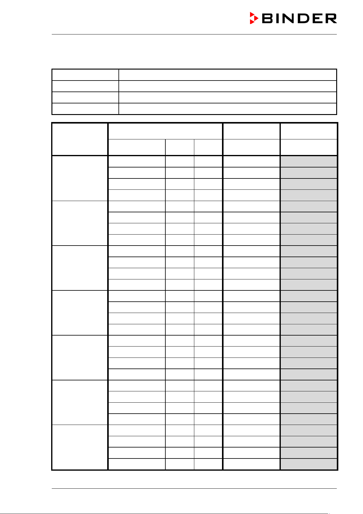
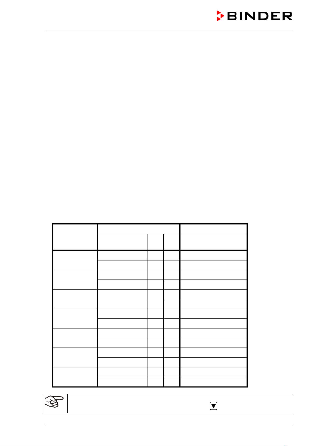
7.1 Program table template for Week program Editor
Program editor
Program title
Project
Date:
hh:mm AM PM ON = SP2
Monday S1
S2
S3
S4
Tuesday S1
S2
S3
S4
Wednesday S1
S2
S3
S4
Thursday S1
S2
S3
ON
S4
Friday S1
S2
S3
S4
Saturday S1
S2
S3
S4
Sunday S1
S2
S3
S4
* Channel 2 is non-functional in the standard chamber
VD (E2.1) 07/2017 page 27/96
Page 28
Day of the week
Time
Channel 1 (temperature)
7.2 Programming example of the Week program editor
7.2.1 Desired time function
During the day (12 hours) the oven shall maintain a temperature of +80 °C / 176°F, and during the night
(12 hours) it shall cool down / stop heating (set-point 30 °C / 86°F).
This program shall automatically run during the whole year, i.e. it shall be programmed just once.
7.2.2 Proceeding overview
1. Settings in the user level (see chap. 10)
• Activating the week program timer
• Checking and, if necessary, setting the real time clock
2. Enter the set-points for the week program in “Fixed value entry mode” (see chap. 6)
Set-points for the example program:
SP1 (night / weekend) = 30 °C (Channel 1 ON = Controller adjusts to set-point SP2)
SP2 (day / week) = 80 °C (Channel 1 OFF = Controller adjusts to set-point SP1)
3. Enter the time program to the program editor
Program table for the example program:
hh:mm AM PM ON = SP2 (day)
OFF = SP1 (night)
Monday S1 06:00 ON
S2 18:00 OFF
Tuesday S1 06:00 ON
S2 18:00 OFF
Wednesday S1 06:00 ON
S2 18:00 OFF
Thursday S1 06:00 ON
S2 18:00 OFF
VD (E2.1) 07/2017 page 28/96
Friday S1 06:00 ON
S2 18:00 OFF
Saturday S1 06:00 ON
S2 18:00 OFF
Sunday S1 06:00 ON
S2 18:00 OFF
Make sure that no other shift points have been pre-programmed. If so, they must be deleted:
Set the time of the respective shift point to “ --:-- ” using key .
Page 29
Display 1 shows
e.g. 39.8 C
(actual temperature value)
program timer channel 1: Off, channel 2: Off)
Display 1 shows
e.g. 0000
Display 2 shows
PROGRAM EDITOR
(you are in the program editor)
Display 1 shows
0000
Menu visible only if week program timer is activated.
Display 2 shows
WEEK PROG. EDITOR
(you are in the week program editor)
Display 1 shows
0000
Display 2 shows
USER – LEVEL
(you are in the user level)
Display 1 shows
0000
Display 2 shows
UserCod?
0000
(enter user code, display flashes)
Display 1 shows 1 (actual address)
(entry of chamber address)
(actual address: 1)
Display 1 shows
0000
(Week program timer active or inactive?
(actual setting: Inactive)
Display 1 shows
0000
(actual setting: 24h)
Display 1 shows
0000
Display 2 shows
Date (Main menu: Setting the date of the real time clock)
7.2.3 Proceeding in detail
1. Settings in the user level
• Activating the week program timer
• Checking and, if necessary, setting the real time clock
Normal Display
Display 2 shows
Enter the user code using arrow keys
e.g. 15.05.06 13:52 - -
Press down key
Press down key
Press down key
Press program key
Automatically forward after 2 sec
(actual date and time, actual switching state of week
for 5 sec
for 5 sec
for 5 sec
e.g. 0001 (basic setting, or the valid code in
case it has been previously changed in this
menu).
Value is shown in both displays.
Display 2 shows Adress 1
Press several times key
Display 2 shows Prog.Clk Inactive
Select “Active” using arrow keys
Display 2 shows 12h/24h 24h
Press program key
VD (E2.1) 07/2017 page 29/96
Press key
Press key
until Prog.Clk appears:
Setting is shown in display 2.
(Display mode 12 hours or 24 hours?
Page 30
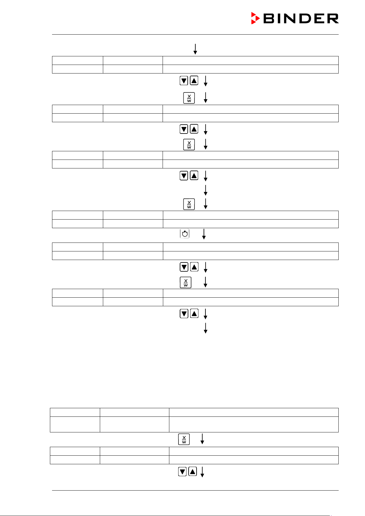
Display 1 shows
e.g. 2006
(Actual setting: 2006)
Display 2 shows
Year
2006
(Setting the year of the real time clock)
Display 1 shows
e.g. 5
(Actual setting: may)
Display 2 shows
Month 5 (Setting the month of the real time clock)
Display 1 shows
e.g. 15
(Actual setting: 15)
Display 2 shows
Day
15
(Setting the day of the real time clock)
Display 1 shows
0000
Display 2 shows
Time (Main menu: Setting the time of the real time clock)
Display 1 shows
e.g. 13
(Actual setting: 13, i.e. 1 p.m.)
Display 2 shows
Hour
13
(Setting the hour of the real time clock)
Display 1 shows
e.g. 30
(Actual setting: 30 minutes)
Display 2 shows
Minute
30
(Setting the minute of the real time clock)
Display 1 shows
e.g. 39.8 C
(actual temperature value)
(actual date and time, actual switching state of week
program timer channel 1: Off, channel 2: Off)
Display 1 shows
30.0 C
(actual temperature set-point 1)
Display 2 shows
SP1 TEMPERATURE
(variable: temperature in °C)
Set year (2006 up to 2050) using arrow
keys
Press key
Set month (1 up to 12) using arrow keys
Press key
Set day (1 up to 31) using arrow keys
Press key
Press key
Press program key
EXIT
Setting is shown in display 2.
Setting is shown in display 2.
Setting is shown in display 2.
Set hour (0 up to 23) using arrow keys
Setting is shown in display 2.
Press key
Set minute(0 up to 59) using arrow keys
Press several times key
EXIT
Setting is shown in display 2.
or wait for 120 seconds
Controller returns to normal display.
2. Enter the set-points for the week program in Fixed value entry mode (see chap.
Set-points for the example program:
SP1 (night / weekend) = 30 °C (Channel 1 ON = Controller adjusts to set-point SP2)
SP2 (day / week) = 80 °C (Channel 1 OFF = Controller adjusts to set-point SP1)
Normal Display
Display 2 shows e.g. 15.05.06 13:52 - -
Press key
6)
Enter temperature set-point 30 °C using
VD (E2.1) 07/2017 page 30/96
Value is shown in display 1.
arrow keys
Page 31

Display 1 shows
80.0 C
(actual temperature set-point 2)
Display 2 shows
SP2 TEMPERATURE
(variable: temperature in °C)
Display 1 shows
e.g. 39.8 C
(actual temperature value)
channel 1: Off, channel 2: Off)
Display 1 shows
e.g. 0000
Display 2 shows
PROGRAM EDITOR
(you are in the program editor)
Display 1 shows
0000
Display 2 shows
WEEK PROG. EDITOR
(you are in the week program editor)
Display 1 shows
0000
Display 2 shows
UserCod?
0000
(enter user code, display flashes)
Display 1 shows
0000
(selection of day of the week)
(actual selection: Monday)
Display 1 shows
0000
Display 2 shows
Shiftpt.
(no function)
Display 1 shows
0000
(actual shift point: 1)
Display 1 shows
e.g. --.--
(time of the selected shift point)
(actual selection of the shift point: S1)
(actual setting: shift point not programmed)
Press key
Enter temperature set-point 80 °C using
arrow keys
Press the EXIT button. The controller changes to Normal Display.
3. Enter the time program to the week program editor
Normal Display
Display 2 shows e.g. 15.05.06 13:52 - -
(actual date and time, actual state of week program timer
Press down key
Press down key
Value is shown in display 1.
for 5 sec
for 5 sec
Press program key
Enter the user code using arrow keys
Automatically forward after 2 sec
Display 2 shows Monday
Select the first day of the week (Monday)
with key
Press program key
Press program key
Display 2 shows Shiftpt. 1
e.g. 0001 (basic setting, adjustable in the
user level, chap. 10).
Value is shown in both displays.
Day of the week is shown in display 2.
(selection of the shift point)
Display 2 shows S1: --:--
VD (E2.1) 07/2017 page 31/96
Select shift point 1 with key
Press program key
Press program key
Value is shown in display 2.
Page 32

Display 1 shows
06.00
(time of the selected shift point)
(actual setting: 6.00, i.e. 6 a.m.)
Display 1 shows
0000
(entry of state of channel 1)
(actual setting: On)
Display 1 shows
06.00
(time of the selected shift point)
(actual selection of the shift point: S1)
(actual setting: time 06.00, channel 1 ON)
Display 1 shows
0000
Display 2 shows
Shiftpt.
(no function)
Display 1 shows
0000
(selection of the shift point)
(actual shift point: 2)
Display 1 shows
e.g. --.--
(time of the selected shift point)
(actual selection of the shift point: S2)
(actual setting: shift point not programmed)
Display 1 shows
18.00
(time of the selected shift point)
(entry of time of the selected shift point)
(actual setting: 18.00, i.e. 6 p.m.)
Display 1 shows
0000
(entry of state of channel 1)
(actual setting: Off)
Display 1 shows
18.00
(time of the selected shift point)
(actual selection of the shift point: S2)
(actual setting: time 18.00, channel 1 OFF)
Display 2 shows Time 06:00
Enter the time 06:00 using arrow keys
Press key
Display 2 shows Ch1 = SP 2: On
Enter the state of channel 1
On using arrow keys
Display 2 shows
S1: 06:00 � -
Press program key
Press program key
Press key EXIT
(entry of time of the selected shift point)
Value is shown in display 2.
Setting is shown in display 2.
to select the next shift point
Display 2 shows Shiftpt. 2
Select shift point 2 with key
Press program key
Display 2 shows S2: --:--
Press program key
Display 2 shows Time 18:00
Enter the time 18:00 using arrow keys
Press key
Display 2 shows Ch1 = SP2: Off
Enter the state of channel 1
Off using arrow keys
Value is shown in display 2.
Value is shown in display 2.
Setting is shown in display 2.
Press key EXIT
Display 2 shows
S2: 18:00 - -
Press key EXIT twice
to select the next day of the week
VD (E2.1) 07/2017 page 32/96
Page 33

Display 1 shows
0000
(selection of day of the week)
(actual selection: Tuesday)
Display 1 shows
0000
Display 2 shows
Shiftpt.
(no function)
Display 1 shows
0000
(selection of the shift point)
(actual shift point: 1)
Display 1 shows
e.g. --.--
(time of the selected shift point)
(actual setting: shift point not programmed)
Display 1 shows
06.00
(time of the selected shift point)
(entry of time of the selected shift point)
(actual setting: 6.00, i.e. 6 a.m.)
Display 1 shows
0000
(actual setting: ON)
Enter the state of channel 1
Display 1 shows
06.00
(time of the selected shift point)
(actual setting: time 06.00, channel 1 ON)
Display 2 shows Tuesday
Select the next day of the week (Tuesday)
with key
Press program key
Press program key
Display 2 shows Shiftpt. 1
Select shift point 1 with key
Press program key
Display 2 shows S1: --:--
Press program key
Day of the week is shown in display 2.
Value is shown in display 2.
(actual selection of the shift point: S1)
Display 2 shows Time 06:00
Enter the time 06:00 using arrow keys
Press key
Display 2 shows Ch1 = SP2: On
On using arrow keys
Display 2 shows S1: 06:00 � -
Press program key
Following entry of the complete program:
Press several times key EXIT
Press key EXIT
etc.
Value is shown in display 2.
(entry of state of channel 1)
Setting is shown in display 2.
(actual selection of the shift point: S1)
to select the next shift point
or wait for 120 seconds
Controller returns to normal display.
VD (E2.1) 07/2017 page 33/96
Page 34

01
02 03
04
05
06
07
08 09
W
t
8. Program editor
8.1 Selecting between set-point r am p and set-point step
You can program various kinds of temperature transitions. In the user level (chap. 10) you can select
between the settings “Ramp” (default setting) and “Step”.
Setting “Ramp” permits programming all kinds of temperature transitions.
With setting “Step” the controller will equilibrate only to constant temperat ures; programming
ramps is no longer possible.
Switching between settings “Ramp” and “Step” will influence all programs. Please note that
this can cause the time courses of existing programs to change significantly.
8.1.1 Programming with setting “Ramp” (default setting)
Set-points always refer to the start of a program section, i.e., at the beginning of each program section,
the entered set-point is reached. During program section operation, the temperature gradually passes to
the set-point entered for the subsequent program section.
You can program all kinds of temperature transitions by the appropriate design of the program section
timing:
• Gradual temperature changes “set-point ramp“
The set-point gradually moves from one set-point to the one of the following program section during a
given interval. The actual temperature value (X) follows the continually moving set-point (W) at any
moment.
• Program sections with constant temperature
The initial values of two subsequent program sections are identical; therefore the temperature remains
constant during the whole time of the first program section.
• Sudden temperature changes “set-point step”
Steps are temperature changes (ramps) that occur during a very short interval. Two program sections
with an identical set-point are followed by a section with a different set-point. If the duration of this
transitional program section is very short (minimum entry 1 min), the temperature change will proceed
rapidly in the minimum amount of time.
Figure 9: Possible temperature transitions
(with default setting “ramp” in the user level (chap. 10)
VD (E2.1) 07/2017 page 34/96
Page 35

W/°C
t/min.
S01
S02
S03
S04
0
20
40
60
80
100
30
120
180
380
S05
Section
SEC
Temperature
Section length
TIME
Operation lines
O.LINE
S01
40
00:30
000
S02
60
01:30
000
S03
90
01:00
000
S04
90
03:20
000
S05
20
00:01
000
W/°C
t/min.
S01 S02 S03 S04 S05 S06 S07 S08
0
20
40
60
80
100
30
120
180
380
Program entry as set-point ramp (example):
Program table corresponding to the diagram (with default setting “Ramp”):
set-point
[ °C]
[hh.mm]
TEMP
You can now enter the values of such a program table to the RD3 program controller (chap. 8.2).
Program entry as set-point step (example):
VD (E2.1) 07/2017 page 35/96
Page 36

Section
SEC
Temperature
Section length
TIME
Operation lines
O.LINE
S01
40
00:30
000
S02
40
00:01
000
S03
60
01:30
000
S04
60
00:01
000
S05
80
01:00
000
S06
80
00:01
000
S07
20
03:20
000
S08
20
00:01
000
W/°C
t/min.
S01 S03 S05 S07
0
20
40
60
80
100
30
120
180
380
Program table corresponding to the diagram (with default setting “Ramp”):
set-point
[ °C]
[hh.mm]
TEMP
You can now enter the values of such a program table to the RD3 program controller (chap. 8.2).
Program the end point of the desired cycle with an additional section (in our examples S05 for set-point
ramp and S08 for set-point step) with a section time of at least one minute. Otherwise, the program will
stop one section too early because the program line is incomplete.
8.1.2 Programming with setting “step”
With setting “Step” selected, you don’t need to program the transition section in the Program Editor.
With setting “step” the controller will equilibrate only to constant temperatures; programmi ng
ramps is no longer possible.
The set-points are maintained constant for the duration of a program section. At the start of each program
section, the chamber heats up with the maximum speed in order to attain the entered set-point
Program entry as set-point step (example):
VD (E2.1) 07/2017 page 36/96
Page 37

Section
SEC
Temperature
Section length
TIME
Operation lines
O.LINE
S01
40
00:30
000
S02
60
01:30
000
S03
80
01:00
000
S04
20
03:20
000
Section
SEC
Temperature set-point
TEMP
Section length
TIME
Operation lines
O.LINE
S01
40
00:30
000
S02
60
01:30
000
S03
90
01:00
000
S04
90
03:20
000
S05
20
00:01
000
Program table corresponding to the diagram (with setting “Step”):
You can now enter the values of such a program table to the RD3 program controller (chap. 8.2).
set-point
[ °C]
TEMP
[hh.mm]
8.1.3 General notes on programming temperature transitions
When exceeding the tolerance limits set in the user level (chap. 10), the program is interrupted until the
actual temperature value returns to within the tolerance range. During this program interruption, the LED
(7d) flashes. Therefore, the duration of the program may be extended due to the programming of
tolerances
The programming is saved even in case of power failure or after turning off the chamber.
After program rundown the controller returns to fixed value operation showing Normal Display and
equilibrates to the temperature value previously entered in fixed value ent ry mode.
Before starting the program, check the set-point value entered in fixed value entry mode.
After program rundown temperature will equilibrate to this value.
Deactivate the week program timer (factory setting, setting in the user level , chap. 10) before
starting a program.
8.2 Set-point entry for program operation
From Normal Display, press down button X/W for 5 sec to access the program editor. Then enter the setpoints one after the other in all program sections of a selected program.
You can enter two programs with up to 10 sections each or one program with up to 20 sections (setting in
the user level, chap. 10).
In order to avoid incorrect programming, we recommend entering the values of the program course into a
table (template in chap. 8.3).
Example of program table (with default setting “Ramp”):
You can now enter the values of the program table to one of the program places of the RD3 program
controller.
[ °C]
[hh.mm]
VD (E2.1) 07/2017 page 37/96
Page 38

Display 1 shows
e.g. 39.8 C
(actual temperature value)
(actual date and time, actual switching state of week
program timer channel 1: Off, channel 2: Off)
Display 1 shows
e.g. 0000
Display 2 shows
PROGRAM EDITOR
(you are in the program editor)
Display 1 shows
0000
Display 2 shows
UserCod? 0000
(enter user code)
Display 1 shows
e.g. 01
(program P01 selected)
Display 2 shows
alternating
--- : --- PRG.
(program can be selected)
CONTINUE X/W
(information: to 1st program section with X/W)
row
Display 1 shows
e.g. 01
(section S01 selected)
X/W
Display 1 shows
e.g. 01
(section S01 selected)
Section S01 has not yet been created.
Step 1 – Selecting the program and the first program section to be entered:
Normal Display
Display 2 shows e.g. 15.05.06 13:52 - -
Press down key
Press program key
Enter user code using arrow keys
Automatically forward after 2 sec.
Select program P01 or P02 using ar
keys
for 5 sec.
e.g. 0001
(basic setting, adjustable in the user level,
chap. 10).
Value is shown in both displays.
Value is shown in display 1.
Press key
In the selected program P01 or P02, program sections can be selected:
Display 2 shows
alternating
P01: --- SEC.
Enter new set-points for the individual variables with button
CONTINUE X/W
Section S01 has already been created.
or:
Display 2 shows
alternating
Select sections S01 to S10 or to S20 using
P01: --- SEC.
NEW SEC. X/W
arrow keys
Enter set-points for the individual variables with button X/W
As long as no program section has been entered, the display switches back to 01 in case of any entry
> 01, because all sections need to be entered one after the other, and each new section is created as
NEWSEC.
Example: If three programs sections have been already entered, the next section to be entered is S04.
Before this, no section > S04 can be selected.
VD (E2.1) 07/2017 page 38/96
Page 39

Display 1 shows
e.g. 40.0 C
(actual temperature set-point)
Display 2 shows
S01: TEMP 40.0
(variable: temperature in °C)
CONTINUE X/W
(information: go on with X/W)
Display 1 shows
e.g. 00.30
(actual section length set-point)
S01: TIME 00:30
(variable: section length in hh:mm)
CONTINUE X/W
(information: go on with X/W)
Display 1 shows
e.g. 000
(actually set switching state)
Display 2 shows
alternating
S01:O.LINE 000
(variable: switching state)
CONTINUE X/W
(Information: go on with X/W)
Display 1 shows
e.g. 02
(section S02 selected)
Display 2 shows
alternating
P01: --- SEC.
Section S02 has already been created.
CONTINUE X/W
Display 1 shows
e.g. 02
(section S02 selected)
Section S02 has not yet been created.
Display 1 shows
e.g. 60.0 C
(actual temperature set-point)
Display 2 shows
S02:TEMP 60.0
(variable: temperature in °C)
CONTINUE X/W
(information: go on with X/W)
Next step – set-point entry in the desired program sections:
Basic entry principle: Access the parameters of individual program sections with button X/W one after
the other. Enter the values of the individual parameters with the arrow keys. A value flashing once after 2
seconds indicates that it has been adopted by the controller. If several parameters are to be skipped (e.g.
in order to change a parameter in a posterior program section), the parameters can be rapidly jumped
over by holding down the X/W key. If no button is pressed for more than 120 sec the controller switches
back to Normal Display. The program entered to this point remains stored.
Press key
alternating
Enter temperature set-point of S01 in °C
using arrow keys
Press key
Display 2 shows
alternating
Enter section length set-point of S01 in
hh.mm using arrow keys
Press key
Enter switching state of operation lines using
arrow keys
Press key
Value is shown in both displays.
(see chap. 15, switching outputs via operation
lines)
Selecting the next program sections to be entered
Enter new set-points for the individual parameters with X/W.
or:
Display 2 shows
alternating
Select the next section to be entered using
P01: --- SEC.
NEW SEC. X/W
arrow keys
Enter set-points for the individual parameters with X/W
alternating
Enter the temperature set-point of S02 in °C
using arrow keys
Etc.
If all sections up to S10 or up to S20 have been programmed, section S01 follows again. In order to quit
the entry mode, press the EXIT button several times or wait 120 sec → the controller will then return to
Normal Display.
When changing the set-point, check the setting of the safety device (chap. 12).
VD (E2.1) 07/2017 page 39/96
Page 40

Program editor
Program title
Project
Program No.
Date:
Section
Temperature set-point
Section length
Operation lines *
8.3 Program table template
SEC
S01
S02
S03
S04
S05
S06
S07
S08
S09
S10
S11
S12
S13
S14
[ °C]
TEMP
[hh.mm]
TIME
O.LINE
S15
S16
S17
S18
S19
S20
* Switching contacts 24V DC via operation lines, see chap. 15.
VD (E2.1) 07/2017 page 40/96
Page 41

Display 1 shows
e.g. 0000
Display 2 shows
PROGRAM EDITOR
(you are in the program editor)
Display 1 shows
0000
Display 2 shows
UserCod? 0000
(enter user code)
Display 1 shows
e.g. 01
(program P01 selected)
alternating
--- : --- PRG.
(program can be selected)
CONTINUE X/W
(information: to 1st program section with X/W)
Display 1 shows
e.g. 01
(actual selection of the section: S01)
Display 2 shows
P01: --- SEC.
(program section can be selected)
CONTINUE X/W
(information: set-point entry with X/W)
Display 1 shows
e.g. 90.0C
(actual temperature set-point)
alternating
S03:TEMP 90.0
(variable: temperature)
CONTINUE X/W
(information: continue with X/W)
Display 1 shows
e.g. 01.00
(actual section length)
Display 2 shows
S03:TIME 01:00
(variable: section length)
CONTINUE X/W
(information: continue with X/W)
for section length in
Display 1 shows
e.g. 00.00
(actual section length)
Display 2 shows
S03:TIME 00:00
(variable: section length)
DELETE SEC. X/W
(information: delete section with X/W)
8.4 Deleting a program section
A program section is deleted from the program by setting the section duration to Zero.
Normal display
Press down key
Press program key
Enter the user code using arrow keys
Automatically forward after 2 sec
Display 2 shows
Select the desired program, e.g. P01, using
arrow keys
Press key
In the selected program P01 or P02, program sections can be selected:
for 5 sec.
e.g. 0001 (basic setting, adjustable in the user
level, chap. 10).
Value is shown in both displays.
Value is shown in display1.
alternating
Select desired section, e.g. S03, using
Display 2 shows
alternating
Enter set-point Zero
hh:mm of S03 using arrow keys
alternating
arrow keys
Press key
Press key
Press key
No entry
(omitted if section S01 shall be deleted).
Value is shown in display 2 or in both displays
(display depends on maximum time setting in
the user level chap. 10)
VD (E2.1) 07/2017 page 41/96
Page 42

Display 1 shows
e.g. 03
(actual selection of the section: S03)
Display 2 shows
alternating
P01:S03
(program section can be selected)
CONTINUE X/W
(information: set-point entry with X/W)
CAUTION
The following section (in our example now S03) is displayed:
Press key
Controller returns to Normal Display
If you delete a program section which is followed by further sections, those following move up
in place of the deleted section.
In our example, section S03 has been deleted. If sections S04, S05, etc. have been programmed earlier,
they will now replace the preceding sections, i.e., S04 is now called S03 etc.
Deletion leads to overwriting the section by the following one. It is therefore not possible to temporarily
inactivate a program section. To enter a section later to a program, all the sections following the new one
must be entered again.
EXIT
or wait 120 sec
9. Program start level
Before starting the program, check the set-point entered in Fixed value operation mode. After end of the
program, the temperature will equilibrate to this value.
Too high or too low temperature after the program ends.
Damage to the charging material.
Check the set-point of Fixed value operation and if necessary adapt it.
After the program ends, the temperature will equilibrate to the set-point entered in Fixed value operation
mode. If the week program timer is active, another set-point (SP2) may be targeted according to
programming. Deactivate the week program timer before starting the program (default setting, setting in
the User level, chap. 10).
CAUTION
Too high or too low temperature after the program ends.
Damage to the charging material.
Deactivate the week program timer before starting the program.
In the first step, select a program. This is on condition that a program has been entered previously (chap.
8.2) and that program type “2 programs with 10 sections each” has been selected in the user level (chap.
10).
Then define the settings for the program course. Two parameters can be set:
• Program delay time, i.e. a defined time before a program starts. It can be entered with a precision of 1
minute, and its maximum value is 99.59 (99 h 59 min). If the value is 00.00, the program will start
immediately.
• Number of program cycles, i.e. the desired number of program repeats. Values from 1 to 99 can be
entered. If the program is not going to be repeated, enter the value “0”. For indefinite repeats enter the
value “–1”. The program is repeated as a whole, it is not possible to repeat individual sections.
In the last step start the selected program. These steps must be carried out subsequently.
VD (E2.1) 07/2017 page 42/96
Page 43

Display 1 shows
e.g. 1
(actual selection of the program)
Display 2 shows
SEL.PRG.
(select program 1 or 2)
Display 1 shows
e.g. 00.00
(entered delay time hh.mm)
Display 2 shows
RUN TIME
(enter delay time of program start)
Display 1 shows
e.g. -1
(actual selection of the number of program cycles)
Display 2 shows
REPEAT
(enter number of program cycles)
Display 1 shows
e.g. 1
(selected program)
Display 2 shows
RUN PRG.
(Question: start selected program?)
Display 1 shows
e.g. 25.5 C
actual temperature value
P01:S01 00:29:39
(time running backwards)
(actual program P01, actual section S01, and remaining
time of program section S01)
Deactivate the week program timer (factory setting, setting in the user level, chap. 10) before
starting a program.
Step 1 – Program selection (only with program type “2 programs” set)
Normal Display
Press program key
Enter program number 1 or 2 with
arrow keys
Next step – entry of program course settings
Press program key
Set delay time in hh.mm using arrow keys
Press program key
Select number of cycles -1, 0, 1 etc. using
arrow keys
Value is shown in display 1.
Value is shown in display 1.
Value is shown in display 1.
Last step – program start
Press program key
Press program key
Display 2 shows
Program is running. The green LED (7d) lights up.
In addition to the green LED (7d) indicating a running program, the LED (7a) is lit if the heating is active,
or not lit if the actual temperature equals the set-point.
During program course the arrow keys and the EXIT button are not functional.
By pressing program key for 3 seconds, you can terminate the program course.
VD (E2.1) 07/2017 page 43/96
Page 44

Display 1 shows
e.g. 65.5 C
(actual temperature value)
(actual program P01, actual section S03, and remaining time
of program section S03)
Display 1 shows
e.g. 90 C
(actual temperature set-point 1)
Display 2 shows
SP1 TEMPERATURE
Display 1 shows
e.g. 30 C
(actual temperature set-point 2)
Display 2 shows
SP2 TEMPERATURE
(no function during program operation)
Display 1 shows
e.g. 000
(actual operation line setting)
Display 2 shows
OPERATION LINE
If you press button during program course, the entered set-point of the actually running program
section is shown for 5 sec:
Display 2 shows P01:S03 00:47:12
Press key
5 seconds
5 seconds
After program rundown (and, if appropriate, of the program repeats) the controller returns to fixed value
operation showing Normal Display and equilibrates to the temperature value previously entered in fixed
value entry mode.
VD (E2.1) 07/2017 page 44/96
Page 45

10. User level
In this menu you can set the following parameters (in brackets the corresponding abbreviated information
given in display 2):
• Chamber address (Adress)
Setting of controller address (1 to 255) for operation with the communication software APT-COM™.
• User code (User-cod)
Modification of the user code setting (factory setting 0001) for access to the user level and the
program editor.
Keep in mind any modification of the user code. There is no access to these levels
without a valid user code.
• Decimal point position (Decimal)
Selection if integer values or one position after the decimal point can be entered. The integer
representation is shown in Display 2 (set-point entry) while the actual value in Display 1 is always
shown with one decimal point.
• Audio Alert (Buzzer)
Inactive: no audible signal (buzzer) in case of an alarm event.
Active: in case of an alarm event (see chap. 11.2) an audible signal (buzzer) will sound. It can be
reset by pressing the EXIT button.
• Selection of controller menu language (Language)
German, English, or French can be selected.
• Counter of operating hours (Oper.hs)
Information about the number of operating hours currently reached or since the last reset (no setting,
display only).
• Max. number of operating hours (Op.limit)
Entry of a limit number of operating hours, i.e., the maximum number of operating hours that can be
run. Maximum setting: 9999. Reaching the limit has no effect.
• Reset operating hours (Op.back)
Reset operating hours to zero.
• Interface protocol (Protocol)
“Modbus”: The chamber interface can be used as a communication interface to connect it to a
computer. This serves to control the chamber by the communication software APT-COM™. It is
possible to read and write the values of all parameters.
“Printer”: A protocol printer for data printouts can be connected to the chamber interface. At the
printer the actual temperature value is regularly protocolled with fixed formatting and with adjustable
print intervals.
In both cases an interface converter RS 422 / RS 232 is used.
• Print interval (Prt.-Inv.)
Setting of the print interval in minutes. Function is available only if setting “Printer” has been selected
in the previous menu point.
• Display illumination (Disp.LED)
Selection between continuous display illumination and limited illumination that will automatically go off
300 sec after the last entry.
VD (E2.1) 07/2017 page 45/96
Page 46

• Program type selection (PrgSelec)
Select between entry of two programs with up to 10 sections each or of one program with up to 20
sections.
When changing from 2 programs to 1 program or vice-versa, existing programs are
deleted in the program editor!
• Maximum section duration (Prg.Time)
The maximum length of an individual program section can be set to either 99 h 59 min or to 999 h 59
min. This setting is then valid for all program sections.
When changing the maximum duration setting, pre-existing programs will be deleted in
the program editor.
• Set-point programming type (Setp.sim)
Selection between “Ramp” and “Step”. With setting „Step“ selected, you don’t need to program the
transition section in the Program Editor.
If you select setting “step”, the controller will equilibrate only to constant temperatures;
programming ramps becomes impossible.
A change between settings “ramp” and “step” will influence all programs. Note that
significant change in time courses may arise in existing programs.
• Tolerance limit range (Tol.band)
Entry of a tolerance limit value in °C. If the actual value of temperature exceeds the set-point of a
program section by more than the entered tolerance limit value, the program is halted (LED (7d)
flashes) until the actual temperature value is again within in the tolerance range
Entry of “0” means tolerance limits are off.
• Activating or inactivating the week program timer (Prog.Clk)
“Inactive”: The week program timer is turned off (factory setting). The corresponding setting menu
(chap. 7) is not visible, nor is is set-point 2 in the “Fixed value entry mode” (chap. 6).
“Active”: The week program timer is activated.
When deactivating the week program timer, any programming made in advance will
remain in memory and take effect when the week program timer is activated again.
Deactivate the week program timer before entering set-points in fixed value entry mode
(chap. 6). Otherwise, any setting of the operation lines is ineffective.
Inactivate the week program timer before staring a program (chap. 9).
• Display mode (12h/24h)
Select between 12 hours (display “AM” or “PM”) or 24 hours.
• Date of the real time clock (Date)
Main menu. Use the program key to access the settings of year, month, and day in the corresponding
submenus.
• Year of the real time clock (Year)
Enter the year (2006 up to 2050)
VD (E2.1) 07/2017 page 46/96
Page 47

Display 1 shows
e.g. 39.8 C
(actual temperature value)
(actual date and time, actual switching state of week
program timer channel 1: Off, channel 2: Off)
Display 1 shows
e.g. 0000
Display 2 shows
PROGRAM EDITOR
(you are in the program editor)
Display 1 shows
0000
Menu visible only if week program timer is activated.
Display 2 shows
WEEK PROG. EDITOR
(you are in the week program editor)
Display 1 shows
0000
Display 2 shows
USER – LEVEL
(you are in the user level)
Display 1 shows
0000
Display 2 shows
UserCod?
0000
(enter user code, display flashes)
Display 1 shows 1 (actual address: 1)
(actual address: 1)
• Month of the real time clock (Month)
Enter the month (1 up to 12).
• Day of the real time clock (Day)
Enter the day (1 up to 31).
• Time of the real time clock (Time)
Main menu. Use the program key to access the settings of hour and minute in the corresponding
submenus.
There is no automatic switch between daylight saving time and regular time.
• Hour of the real time clock (Hour)
Enter the hour (0 up to 23).
• Minute of the real time clock (Minute)
Enter the minute (0 up to 59).
Display 2 shows e.g. 15.05.06 13:52 - -
Press down key
Press down key
Press down key
Press program key
Enter the user code using arrow keys
Normal Display
for 5 sec
for 5 sec
for 5 sec
e.g. 0001 (basic setting,
or the valid code in case it has been previously
changed in this menu).
Value is shown in both displays.
Display 2 shows Adress 1
Enter the chamber address (1 up to 254)
using arrow keys
VD (E2.1) 07/2017 page 47/96
Automatically forward after 2 sec
(entry of chamber address)
Address is shown in both displays.
Press key
Page 48

Display 1 shows 1 (actually valid user code: 1)
(actually set: 1)
Display 1 shows
0000
(no function)
Display 2 shows
Saf.mode: Limit
(no function)
Display 1 shows
0
(no function)
Display 2 shows
Saf.setp
0
(no function)
Display 1 shows
0000
(no function)
(setting of decimal point position)
(actual setting: XXX.X)
using arrow
Display 1 shows
0000
(no function)
Display 2 shows
(setting of the alarm buzzer)
(actual setting: „Active“)
using
Display 1 shows
0000
(no function)
(actual setting: English)
Select between languages German,
Display 1 shows
e.g. 0004
(chamber operating hours)
(operating hours up to now hhhh:mm)
(actually displayed: 4 hs 28 min)
Display 1 shows
1000
(actual setting: 1000 hs)
1000:00 (maximum number of operating hours
hhhh:mm (actual setting: 1000 hs)
Display 1 shows
0000
(no function)
(reset counter of operating hours ?)
(actual setting: No)
using arrow
Display 2 shows User-cod 1
Enter a new value using arrow keys
Press key
Press key
Press key
Display 2 shows Decimal: XXX.X
Select decimal point position
Press key
keys
(change user code)
Value is shown in both displays.
Decimal point position XXX.X or XXXX. is
shown in display 2.
Buzzer : Active
Select between “Active” and “Inactiv”
arrow keys
Press key
Display 2 shows Language : English
English, and French using arrow keys
Press key
Display 2 shows Oper.hs 0004:28
Press key
Display 2 shows Op.limit
Set value using arrow keys
Setting is shown in display 2.
(selection of controller language)
Setting is shown in display 2.
Setting is shown in both displays.
Display 2 shows Op.back : No
Select between “Yes” and “No”
VD (E2.1) 07/2017 page 48/96
Press key
keys
Setting is shown in display 2.
Page 49

Display 1 shows
0000
(no function)
(actual setting: Modbus)
Display 1 shows
e.g. 3
(actual setting: 3 min)
(print interval)
(actual setting: 3 min)
Display 1 shows
0000
(continuous display illumination?)
(actual setting: No)
using arrow
Display 1 shows
0000
(1 program with max. 20 sections or
(actual setting: 2Prg10S)
Select between “2Prg10S” and “1Prg20S”
Display 1 shows
0000
(max. section length 99:59 or 999:59?)
(actual setting: 99:59)
Select between 99:59 in hh:mm or 999:59 in
Display 1 shows
0000
(ramp or step?)
(actual setting: ramp)
using arrow
Display 1 shows
0000
(actual setting: 0)
Display 1 shows
0000
(Week program timer active or inactive?
(actual setting: Inactive)
Press key
Display 2 shows Protocol: MODBUS
Select between protocols “MODBUS” and
“Printer” using arrow keys
Press key
Display 2 shows Prt-Inv. 3
Select value between 0 and 255 minutes
using arrow keys
Press key
Display 2 shows Disp.LED: No
Select between “Yes” and “No”
Press key
Display 2 shows PrgSelec: 2Prg10S
keys
(Selection of interface mode)
Setting is shown in display 2.
Setting is shown in displays 1 and 2.
Setting is shown in display 2.
2 programs with max. 10 sections each?)
using arrow keys
Press key
Display 2 shows Prg.Time: 99:59
hhh:mm using arrow keys
Press key
Display 2 shows Setp.sim Ramp
Select between Ramp and Step
Press key
Display 2 shows Tol.band 0
Set value in °C using arrow keys
keys
Setting is shown in display 2.
Setting is shown in display 2.
Setting is displayed in display 2.
(Tolerance limits in °C)
Setting is shown in display 2.
Display 2 shows Prog.Clk Inactive
VD (E2.1) 07/2017 page 49/96
Press key
Page 50

Display 1 shows
0000
(Display mode 12 hours or 24 hours?
(actual setting: 24h)
Display 1 shows
0000
Display 2 shows
Date (Main menu: Setting the date of the real time clock)
Display 1 shows
e.g. 2006
(Actual setting: 2006)
Display 2 shows
Year
2006
(Setting the year of the real time clock)
using arrow
Display 1 shows
e.g. 5
(Actual setting: may)
Display 2 shows
Month 5 (Setting the month of the real time clock)
Display 1 shows
e.g. 15
(Actual setting: 15)
Display 2 shows
Day
15
(Setting the day of the real time clock)
Display 1 shows
0000
Display 2 shows
Time (Main menu: Setting the time of the real time clock)
Display 1 shows
e.g. 13
(Actual setting: 13, i.e. 1 p.m.)
Display 2 shows
Hour
13
(Setting the hour of the real time clock)
Display 1 shows
e.g. 30
(Actual setting: 30 minutes)
Display 2 shows
Minute
30
(Setting the minute of the real time clock)
Select between “Active” and “Inactive” using
arrow keys
Setting is shown in display 2.
Press key
Display 2 shows 12h/24h 24h
Select between 12 hours and 24 hours
using arrow keys
Press key
Set year (2006 up to 2050)
Set month (1 up to 12) using arrow keys
Setting is shown in display 2.
Press program key
keys
Press key
Press key
Setting is shown in display 2.
Setting is shown in display 2.
Set day (1 up to 31) using arrow keys
Press key
Press key
Press program key
Set hour (0 up to 23) using arrow keys
Press key
Set minute(0 up to 59) using arrow keys
Press several times key
Controller returns to normal display.
EXIT
EXIT
Setting is shown in display 2.
Setting is shown in display 2.
Setting is shown in display 2.
or wait for 120 seconds
VD (E2.1) 07/2017 page 50/96
Page 51

(2)
(2a)
(2b)
11. Performance in case of failures
11.1 Performance after power failure
Power failure during fixed-value operation (Normal Display):
The entered parameters remain saved. After power returns operation continues with the set parameters.
Power failure during program operation:
After the power returns, program course continues with the set-points that have been reached previously
during program operation.
11.2 Alarm messages
Alarm messages, e g. “RANGE ERROR CH1” in case of sensor rupture, are shown in Display 2 only in
Normal Display.
A buzzer can be activated / deactivated in the user level (chap. 10). It can be reset by pressing the EXIT
button. The alarm text shown in Normal Display goes off only if the cause of the alarm does not exist any
longer.
12. Temperature safety device class 2
The chamber is equipped with a temperature safety device class 2 (temperature limiter) acc. to DIN
12880:2007. The safety device protects the vacuum drying oven, its environment and the charging
material from exceeding the maximum permissible temperature.
Please observe the DGUV guidelines 213-850 on safe working in laboratories (formerly BGI/GUV-I 8500, BGR/GUV-R 120 or ZH 1/119, issued by the employers’ liability insurance association) (for Germany).
The temperature safety device only activates after the set-point has been reached once.
In the event of a fault in the temperature controller, the safety device (2) permanently turns off the
vacuum drying oven. This status is reported visually by the indicator lamp (2a).
Check the operation of the safety device (2) by moving it slowly counter-clockwise until it is turne d off.
The safety device cut-off is reported visually by the indicator lamp (2a).
Then release the safety device by pressing the reset button (2b), and turn on the VD vacuum drying oven
as described previously.
Figure 10: Temperature safety device class 2
VD (E2.1) 07/2017 page 51/96
Page 52

• Turn the control knob (2) of the safety device using a coin to its
When the set point is reached, turn back the control knob (2) until
The red alarm lamp (2a) lighting up identifies the trip point; and the
The optimum setting of the safety device is obtained by turning the
Function:
The safety device is functionally and electrically independent of the temperature control device and turns
off the chamber at all poles.
If you turn the control knob (2) to its end-stop (position 10), the safety device will protect the appliance. If
you set it to a temperature a little above the set-point temperature, i t will protect the charging material.
If the safety device has turned off the oven, identifiable by the red alarm lamp (2a) lighting up, proceed as
follows:
• Disconnect the oven from the power supply
• Have an expert examine and rectify the cause of the fault
• Release the safety device by pressing the reset button (2b)
• Restart the oven as described in chap. 4.4.
Adjustment:
To check the response temperature of the safety device, turn on the chamber and set the desired set
point on the temperature controller.
The scale division from 1 to 10 corresponds to the temperature range from 30° / 86°F up to 320 °C /
608°F and serves as a setting aid.
end-stop (position 10) (chamber protection).
•
its trip point (turn it counter-clockwise) is reached.
•
reset button (2b) pops out.
•
knob clockwise by approx. one graduation mark on the scale.
• Push the reset button (2b) in again.
Figure 11: Setting the safety
device class 2
The chamber is only active when the reset button (2b) is pushed in.
When the safety device responds, the red alarm lamp (2a) illuminates, the reset button (2b) pops out, and
the oven is turned off permanently at all poles.
Check the setting regularly and adjust it following changes of the set-point or charge.
Function check:
Check the temperature safety device class 2 at appropriate intervals for its functionality. It is
recommended that the authorized operating personnel should perform such a check, e.g., before starting
a longer work procedure.
VD (E2.1) 07/2017 page 52/96
Page 53

13. Reference measurements. Checking the temperature in the inner chamber
The controller display was adjusted in the factory to the temperature in the center of the usable volume
(chap. 20.1). The sensor probe of the reference measuring device was connected tightly to an expansion
rack positioned in the middle of the chamber.
Checking the controller display
• Conduct the reference sensor into the inner chamber through the measuring port (17). The port must
be largely vacuum tight to enable a typical operation vacuum for the calibration. For a high vacuum,
use a measuring access port. Usually, a silicone plug with a hole for the sensor wire is sufficient.
• Fix the sensor to the center of an expansion rack in the middle of the useable volume with adhesive
aluminum tape or thermal conductive paste to ensure sufficient thermal conductivity.
• Perform the measurement in a thermally stable condition with 3 expansion racks and empty oven.
• Equilibrating time: at least 12 hours.
Checking the spatial temperature exactitude
• Fix at least 9 sens or probes on 3 racks w ith adhesive aluminum tape or thermal conductive paste to
ensure sufficient thermal conductivity
• The distance of the sensor probes to all inner chamber walls must be at least 10% of the
corresponding inner chamber dimension (see DIN 12880).
• Perform the measurement in a thermally stable condition with 3 expansion racks and empty oven.
• Response time: at least 12 hours.
Do NOT use the temperature probe of the reference measurement device without any contact
to the expansion rack, i.e., do NOT measure vacuum values!
In case the temperature probe is a thermo element, mount it so it is electrically insulated from
the rack.
If you note an excessive divergence between the controller and reference temperatures, please contact
BINDER Service to calibrate the temperature controller.
14. Commissioning the vacuum
With regard to operation, please observe the DGUV guidelines 213-850 on safe working in laboratories
(formerly BGI/GUV-I 850-0, BGR/GUV-R 120 or ZH 1/119, issued by the employers’ liability insurance
association) (for Germany).
Starting situation: The vacuum source is connected and ready for operation.
For the vacuum module with chemical membrane pump option, see chap. 16.3 and 16.4.
VD (E2.1) 07/2017 page 53/96
Page 54

• Turn on the vacuum pump.
14.1 Evacuation
• VD 23: Close the air/gas valve (4).
• VD 53 and VD 115: Close the aeration valve (5) and the fine dosing valve for inert gas (6).
• Put the lever of the vacuum shut off valve (8) to
“ON” position (valve open).
• Monitor the internal pressure on the pressure
display (3). The analog manometer displays the
running evaporation respectively the end of the
drying procedure. The scale of the manometer (3)
refers to an ideal ambient pressure of 1013 mbar
/ 29.9 inHg. Tolerance: 50 mbar / 37.5 mm Hg
(Torr) / 1.48 inch Hg (2.5% of the final scale value
+ reading precision). The optional digital pressure
display (chap. 16.5) offers an absolute scale.
• When the desired end vacuum is obtained, turn
the VDL vacuum shutoff valve (8) to the “OFF”
position (valve closed). The reached vacuum is
now maintained.
Figure 12: Manometer display
The permissible end vacuum is 10-2 mbar / 0.0003 inHg.
As long as there is a vacuum, never try to open the oven by force.
14.2 Breaking the vacuum (flooding with ambient air)
When the drying procedure is complete, the vacuum in the inner container is broken (flooded).
VD 23:
• Open air/gas valve (4)
Fresh air is sucked in through the inert gas connection (12)
VD 53, VD 115:
• Open aeration valve (5)
Fresh air is sucked in through the lateral ventilation slots of the instrument box.
• Open fine dosing valve for inert gas (6)
Fresh air is sucked in through the inert gas connection (12)
The fresh air is introduced into the lower part of the rear panel of the inner chamber and is evenly
distributed in the inner chamber. This supply of fresh air by under-flooding prevents turbulence of
pulverized drying material.
VD (E2.1) 07/2017 page 54/96
Page 55

off the inert gas supply: Close
14.3 Operation with inert gas
When operating the VD vacuum drying oven with inert gas, correctly follow the technical ventilation
measures, as described in the DGUV guidelines 213-850 on safe working in laboratories (formerly
BGI/GUV-I 850-0, BGR/GUV-R 120 or ZH 1/119, issued by the employers’ liability insurance association)
(for Germany).
Inert gases in high concentrations are hazardous to health. They are colorless and almost odorless and
therefore practically imperceptible. Inhalation of inert gases can cause drowsiness up to respiratory
arrest. When the O
Any gas that might escape has to be led out via good room ventilation or a suitable exhaust system.
content of the air decreases below 18%, there is risk of death from lack of oxygen.
2
WARNING
High concentration of inert gas.
Risk of death by suffocation.
∅ Do NOT set up chambers in non-ventilated recesses.
Ensure technical ventilation measures.
Respect the relevant regulations for handling these gases.
When decommissioning the vacuum drying oven, shut
valves (4) or (6).
Install a pressure reducer for inert gas operation. Set the pressure reducer to a pressure slightly above
ambient pressure. Ensure that the pressure reducer will open. Do not change this setting in order to avoid
perturbation inside the oven and release of big quantities of inert gas after flooding the VD.
Following evacuation, an inert gas, e.g., nitrogen, is led into the inner chamber via the air/gas valve (4)
(VD 23) or the fine dosing valve for inert gas (6) (VD 53, VD 115), until pressure compensation with the
atmosphere occurs. Depending on the individual application, you can perform a second evacuation and
repeat the inert gas flooding.
When the inert gas fine dosing valve is open, a maximum of approx. 0.6 m³/h gas flows into the inner
chamber. The introduction of inert gas by under-flooding in the lower region of the inner chamber rear
wall and the extraction at the inner chamber ceiling allow an effective inert gas flushing.
If the oven is charged to full capacity, depending on the load, deviati ons f rom the specified
heating up times may occur.
VD (E2.1) 07/2017 page 55/96
Page 56

Operation line 1
Operation line 2
Operation line 3
(no function)
1
0
0
Operation line 1 ON
0 1 0
Operation line 2 ON
1
1
0
Operation lines 1 and 2 ON
0 0 0
Operation line OFF
24 V DC +
24 V DC -
1 2 3
15. Switching contacts 24V DC via operation lines
Operation lines 1 and 2 are used to switch on and off electrical equipment (nominal voltage 24 V DC,
current consumption max. 0.4 A). The switching contacts are connected with two DIN sockets (13) and
(14) at the chamber rear.
The operation lines permit switching on and off the switching contacts by program control. You can
program the operation lines in “Fixed value entry mode” (chap. 6) as well as in the “Program editor”
(chap. 8.2) via the operation lines (switching state “0” = Off, switching state “1” = On).
Set the positions “100” or “010” or “110” or “000” as follows:
You can combine any of the switching states of the operation lines. You can recognize switching state
ON when the LED (7b) for operation line 1 and the LED (7c) for operation line 2 light up.
Operation lines 1 and 2 are designed for the following options:
• Operation line 1: Program controlled evacuation (option “vacuum module with pump”, see chap. 16.3)
• Operation line 2: Program controlled venting (option “program controlled venting”, available via
BINDER INDIVIDUAL customized solutions)
You can connect any other device or electrical equipment with a nominal tension of 24 V DC and a
current consumption of max. 0.4 A.
Establish the connection via the DIN sockets at the rear of the oven:
Figure 13: Pin configuration of the DIN sockets (15) and (16)
OPERATION LINE 2
OUTPUT
OPERATION LINE 1
OUTPUT
Figure 14: Legend at the DIN socket (15) Figure 15: Legend at the DIN socket (16)
A suitable DIN plug is enclosed.
VD (E2.1) 07/2017 page 56/96
24V DC / MAX. 0,4A
24V DC / MAX. 0,4A
Page 57

The VD connection kit VD (Art. no. 8012-0146)
(19)
(18)
Maximum loading capacity of the switching contacts: 0.4 Amp.
CAUTION
Overloading the switching contacts.
Damage to the switching contacts and connection sockets.
∅ DO NOT exceed the maximum switching load of 0.4 Amp.
∅ DO NOT connect any device with a higher load.
ONLY connect devices with a nominal tension of 24 V DC.
16. Options
16.1 Connection kit VD (option)
consists of:
• Aluminum straining ring DN10/16
• Outer centering ring DN10/16
• Small flange with hose tulles DN16/8
• 2.5 m / 98.4 in caoutchouc hose 6/12 mm
• 2 hose clamps
Figure 16: VD connection kit VD
16.2 Vacuum module empty (without pump) (option)
The mounting instructions Art. no. 7001-0137 supplied with the vacuum module describe
how to mount the VD vacuum drying oven onto the vacuum module and installing the
suction line into the vacuum module.
A switch (18) is located at the front of the vacuum module for switching a vacuum pump via the socket
(19) permanently fitted in the vacuum module.
Figure 17: Vacuum module with the switch and socket for the vacuum pump
(18) Switch for the vacuum pump
(19) Socket for the vacuum pump
VD (E2.1) 07/2017 page 57/96
Page 58

(13)
. The module
e permissible end vacuum or limit the end vacuum via a
Maximum admissible load of the socket:
Standard 230 V / 50 Hz - 16 Amp
cUL-version 120 V / 60 Hz - 13 Amp
With CUL-version, connect only a UL listed vacuum pump with ratings of 120 V AC, 60 Hz,
and less or equal 12 Amp, 0.5 HP.
Connection to a vacuum source
Connect the vacuum connection (13) (small flange DN 16) at the
rear of the chamber at the top to a vacuum pump or to a domestic
vacuum system via a vacuum hose or a fixed vacuum pipe.
When using a vacuum hose, we recommend using the BINDER
connection kit VD Art. no. 8012-0146 (chap. 16.1
has an appropriate hose outlet at the back.
Figure 18: VD 53 with option “Vacuum module”, mounted, and
installed vacuum hose
VD (E2.1) 07/2017 page 58/96
CAUTION
Technical defects due to excessive negative pressure.
Danger of implosion.
Damage to the chamber.
∅ The end vacuum must NOT fall below the permissible level of 10
Install the pump according to th
vacuum controller.
-2
mbar / 0.0003 inHg.
WARNING
Release of extracted vapors.
Danger of injury.
Damage to oven and pump by corrosion.
Remove the extracted vapors from the module via a suitable hose into e.g., a fume
extractor facility.
Connect the hose to the vacuum pump outlet.
Page 59

(15)
(15) DIN socket (operation line 2) for option
DIN socket at the vacuum module for
(19)
(18)
16.3 Vacuum module with chemical membrane pump VP 1.1 or VP 2.1 (option)
The mounting instructions Art. no. 7001-0137 supplied with the vacuum module describe
how to mount the VD vacuum drying oven onto the vacuum module and installing the
suction line into the vacuum module.
(16)
(20)
(21)
(22)
program controlled venting
(16) DIN socket (operation line 1) for option
vacuum module with pump
(20)
option vacuum module with pump
(21) Power supply at vacuum module
(22) Fuse
Figure 19: VD 53 w ith option “Vacuum module
with chemical membrane pump”, mounted
A switch (18) is located at the front of the vacuum module for switching the vacuum pump via the socket
(19) permanently fitted in the vacuum module.
Figure 20: Vacuum module with switch and socket for vacuum pump
(18) Switch for vacuum pump
(19) Socket for vacuum pump
VD (E2.1) 07/2017 page 59/96
Page 60

d vapors from the module via a suitable hose into e.g., a fume
Connect the hose to the vacuum pump outlet (hose olive at the back of the emission
denser of the vacuum pumps
Maximum admissible load of the socket:
Standard 230 V / 50 Hz - 16 Amp
cUL-version 120 V / 60 Hz - 13 Amp
With cUL-version, connect only a UL listed vacuum pump with ratings of 120 V AC, 60 Hz,
and less or equal 12 Amp, 0.5 HP.
The VP 1.1 or VP 2.1 membrane pump is located in a separate transport packaging. With this option, the
mounted system, consisting of VD and vacuum module, has a total of two power supply leads.
Installation of the supplied vacuum pump
• The vacuum drying oven is mounted onto the vacuum module as described in the mounting
instructions Art. No. 7001-0137.
• The suction line is installed to the vacuum module as described in the mounting instructions Art. No.
7001-0137.
• When the pump is removed from the original packaging, place it in the vacuum module.
• Push the pre-installed suction line onto the opening of the vacuum pump (13) hose olive above the
suction-side condensate piston).
• Insert the shockproof plug of the vacuum pump into the permanently installed socket (19) in the
vacuum module.
• Push a suitable hose for removing the extracted vapors from the module onto the pressure-side
connection of the vacuum pump (hose olive at the back of the emission condenser at the top).
• Lead the hose end into an exhaust air unit.
• Connect DIN socket (20) at the vacuum module to DIN socket (16) at the chamber rear via the
supplied 1.2 m cable.
As soon as the connection between DIN sockets (16) and (20) is established, it is not possible
to manually switch the pump via switch (18).
To permit switching on and off the pump via operation line 1, keep switch (18) switched on
(position I).
WARNING
Release of extracted vapors.
Danger of injury.
Damage to oven and pump by corrosion.
Remove the extracte
extractor facility.
condenser at the top).
You can connect a laboratory cooling system to the emission con
VP 1.1 or VP 2.1.
For operating the chemical membrane pumps VP 1.1 (MZ2C) and VP 2.1 (MD4C), please
refer to the enclosed pump manufacturer's operating manual.
VD (E2.1) 07/2017 page 60/96
Page 61

Operation condition
Inlet pressure
Permitted gas temperature
Continuous operation
> 100 mbar / 2.95 inHg (high gas load)
+10 °C to +40 °C / 50°F to
104°F
Continuous operation
< 100 mbar / 2.95 inHg (low gas load)
0 °C to +60 °C / 32°F to 140°F
Short-time operation (< 5 min.)
< 100 mbar / 2.95 inHg (low gas load)
-10 °C to +80 °C / 50°F to 176°F
CAUTION
Operation condition
Inlet pressure
Permitted gas temperature
Continuous operation
> 100 mbar / 2.95 inHg (high gas load)
+10 °C to +40 °C / 50°F to 104°F
Continuous operation
< 100 mbar / 2.95 inHg (low gas load)
0 °C to +60 °C / 32°F to 140°F
Short-time operation (< 5 min.)
< 100 mbar / 2.95 inHg (low gas load)
-10 °C to +80 °C / 50°F to 176°F
Observe the permitted gas temperature. The following values refer to the maximum ambient temperature
of the pump of 40 °C / 104°F.
Do not exceed the permitted gas inlet temperature. An excessive gas inlet temperature may diminish the
lifetime of the pump.
Exceeding the gas inlet temperature.
Damage to the vacuum pump.
∅ Do NOT exceed the set-point temperature of the permitted gas temperature.
With higher set-point temperature, take appropriate measures to cool down the sucked-
in gas before its entry to the vacuum pump
16.4 Vacuum module with speed controlled chemical membrane pump VP 3.1
and vacuum controller (option)
This option consists of:
• The pump stand with speed-controlled chemical vacuum pump VP 3.1 (suction power 4.6 m
vacuum controller CVC3000
• Vacuum module with accompanying mounting instructions
The mounting instructions 7001-0137 delivered with the vacuum module describe
mounting the vacuum drying oven onto the vacuum module and installing the suction l ine
to the vacuum module.
The chemical vacuum pump and the vacuum controller are delivered ready-assembled as a vacuum
pump stand in separate transport packaging. For installation and connection, see chap. 16.3.
Do NOT connect DIN sockets (16) and (20) when using this option.
To permit switching on and off the pump, keep switch (18) switched on (position I).
3
/h) and
For operating the chemical membrane pump VP 3.1 (MD4C Vario), please refer to the
enclosed pump manufacturer's operating manual.
Observe the permitted gas temperature. The following values refer to the maximum ambient temperature
of the pump of 40 °C / 104°F.
VD (E2.1) 07/2017 page 61/96
Page 62

Turn off the pump unit at its main
press down
the selection knob
Turn off the pump unit at ON/OFF
RS - 232
Do not exceed the permitted gas inlet temperature. An excessive gas inlet temperature may reduce the
pump’s lifetime.
CAUTION
Exceeding the gas inlet temperature.
Damage to the vacuum pump.
∅ Do NOT exceed the set-point temperature of the permitted gas temperature.
With higher set-point temperature, take appropriate measures to cool down the sucked-
in gas before its entry to the vacuum pump
Programming of descendant pressure cycles as well as documentation of pressure data are possible via
the RS 232 serial interface of the vacuum controller CVC 3000 by use of the BINDER communication
software APT-COM™ DataControlSystem (option, chap. 16.8).
In combination with the option object temperature measurement a T-formed connection tube
adapter (small flange DN16 (Art. No. 6009-0060) NOT included) is necessary to connect the
pressure sensor of the vacuum controller to the measuring access port.
Settings of the vacuum controller for control via APT-COM™:
Following settings are necessary to set the vacuum controller to remote control via its RS232 interface
and to enable the venting valve:
Setting for remote control:
• With the MODE key select the menu “Configuration”.
• Select the menu point “RS – 232” with the selection knob and set the setting “Remote” to “On”.
• Set the Baud rate to 9600.
Configuration RS - 232
Adjustment 936 mbar
RS – 232 . . .
Sensors . . .
Display . . .
Autostart Off
Baud 9600
Parity 8 - N - 1
Handshake Xon - Xoff
Remote On
- - - - - - Back - - - - - -
Defaults Cancel
- - - - - - Back - - - - - -
The vacuum controller can no longer be operated manually in this mode.
Resetting to manual operation:
power switch. Then turn it on again
and within 1 second
simultaneously
and the ON/OFF key.
OR
key. Then turn it on again and within
1 second press the selection knob.
VD (E2.1) 07/2017 page 62/96
Baud 9600
Parity 8 - N - 1
Handshake Xon - Xoff
Remote Off
- - - - - - Back - - - - - -
Page 63

Display 1 shows
e.g. 24.6 C
(actual temperature value)
Display 2 shows
24.4 15:41
(actual object temperature in °C, actual time)
Then select the menu point “RS - 232” with the selection knob and set the setting “Remote” to “Off .
16.5 Digital pressure display (option)
With this option, a digital display indicates the internal pressure with the accuracy of 1 mbar / 0.03 inHg.
The pressure is measured by a permanently fitted internal pressure sensor.
A service engineer can calibrate and internally adjust the digital pressure display.
Figure 21: Digital display of internal pressure
16.6 Additional measuring channel for digital object temperature display with
flexible Pt 100 temperature sensor (option)
The object temperature display permits recording the object temperature directly on or in the drying
material. The object temperature is measured via a flexible Pt100 sensor inside the inner chamber. The
sensor needs to be in thermally conducting contact with the charging material. It can be plunged into
humid charging material up to the length of its protecting tube.
The object temperature is indicated on Display 2 of the RD3 controller.
Figure 22:
Standard Display without the
object temperature display option
The object temperature data is put out combined with the temperature data of the temperature controller
to the RS 422 interface as a second measuring channel. This permits recording by the BINDER
documentation software APT-COM™ DataControlSystem (option, chap. 16.8).
object temperature display option
Figure 23:
Display with the
Assembly and connection of the object temperature recording
• Insert the Pt 100 temperature sensor from the rear through the measuring connection (17) into the
inner chamber.
• The 3 contacts of the Pt 100 sensor are conducted outside via a measuring access port. From there,
establish the connection to the DIN socket at the top of the rear panel of the chamber marked “Pt100”.
VD (E2.1) 07/2017 page 63/96
Page 64

Figure 24: Measuring connection (17) with
Figure 25: Pt100 connection (14) at the rear of the
/
measuring access port
Technical data of the Pt 100 sensor:
• Three-wire technique
• Class B (DIN EN 60751)
• Temperature range up to 300 °C / 572°F
• Stainless steel protective tube, length 45 mm / 1.77 in, stainless steel material no. 1.4501
chamber
16.7 Measuring access port vacuum 9 poles (option)
The measuring access port allows creating electrical connections for low voltages or sensors between
the exterior and interior of the VD vacuum drying oven. A 9 poles plug for the out side is included.
Figure 26: Measuring connection (17) with measuring access
port and supplied plug
Connections at the measuring access port
• At the inner side of the measuring access port you can solder up to 9 cables. The inside connections
must be insulated against each other and against ground. Use 300 °C / 572 °F solder.
• The 9 contacts are conducted outside via the measuring access port. You can use them to connect a
device via the delivered plug.
Maximum load capacity of the switching contacts: 42 V AC/DC - 2A
Electrical hazard.
Danger of death.
Damage to switching contacts and connection socket.
VD (E2.1) 07/2017 page 64/96
∅ Do NOT exceed the maximum switching load of 42 AC/DC – 2Amp.
∅ Do NOT connect any devices with a higher load capacity.
Insulate the inside connections against each other and against ground. Use 300 °C
572 °F solder.
DANGER
Page 65

Pin allocation of the RS 422 interface (9):
pin 2: RxD (+)
pin 7: GND
at the main power switch
or experts
16.8 Communication software APT-COM™ 3 DataControlSystem (option)
The chamber is regularly equipped with a serial interface RS 422 (9) that can connect the BINDER
communication software APT-COM™ 3 DataControlSystem. The actual temperature value is given at
adjustable intervals. Programming can be performed graphically via PC. Up to 30 chambers with RS 422
interface can be cross-linked. For further information, refer to the operating manual of the BINDER
communication software APT-COM™ 3.
Confirm that the interface mode is correctly set to “Modbus” in the user level (chap. 10).
pin 3: TxD (+)
pin 4: RxD (-)
pin 5: TxD (-)
17. Maintenance, cleaning, and service
17.1 Maintenance intervals, service
DANGER
Electrical hazard.
Danger of death.
∅ The chamber must NOT become wet during operation or maintenance work.
∅ Do NOT remove the rear panel of the chamber.
Before conducting maintenance work, turn off the chamber
and disconnect the power plug.
Ensure all maintenance work is conducted by licensed electricians
authorized by BINDER.
Ensure regular maintenance work is performed at least once a year.
The warranty becomes void if maintenance work is conducted by non-authorized personnel.
Replace the door gasket only when cold. Otherwise, the door gasket may become damaged.
We recommend taking out a maintenance agreement. Please consult BINDER Service.
BINDER telephone hotline: +49 (0) 7462 2005 555
BINDER fax hotline: +49 (0) 7462 2005 93555
BINDER e-mail hotline: service@binder-world.com
BINDER service hotline USA: +1 866 885 9794 or +1 631 224 4340 x3 (toll-free in the USA)
BINDER service hotline Asia Pacific: +852 390 705 04 or +852 390 705 03
BINDER service hotline Russia and CIS +7 495 988 15 16
BINDER Internet website http://www.binder-world.com
BINDER address BINDER GmbH, post office box 102, D-78502 Tuttlingen
International customers, please contact your local BINDER distributor.
VD (E2.1) 07/2017 page 65/96
Page 66

at the main power switch and
17.2 Cleaning and decontamination
Clean the chamber after each use to avoid potential corrosion damage by ingredients of the charging
material.
DANGER
Electrical hazard.
17.2.1 Cleaning
Danger of death.
∅ Do NOT spill water or cleaning agents over the inner and outer surfaces.
Before cleaning, turn off the chamber
disconnect the power plug.
Completely dry the appliance before turning it on again.
Disconnect the oven from the power supply before cleaning. Disconnect the power plug.
The interior of the chamber must be kept clean. Thoroughly remove any residues of the
charging material
Wipe the surfaces with a moistened towel. In addition, you can use the following cleaning agents:
Exterior surfaces,
inner chamber,
door gaskets
Expansion racks,
rack holders
Instrument panel Standard commercial cleaning detergents free from acid or halides.
Zinc coated hinge parts
rear chamber wall
Do not use cleaning agents that may cause a hazard due to reaction with components of the device or
the charging material. If there is doubt regarding the suitability of cleaning products, please contact
BINDER service.
Standard commercial cleaning detergents free from acid or halides.
Alcohol based solutions.
We recommend using the neutral cleaning agent Art. No. 1002-0016.
Standard commercial cleaning detergents free from acid or halides, no salt
solution or chlorinated solvents.
We recommend using the neutral cleaning agent Art. No. 1002-0016.
We recommend using the neutral cleaning agent Art. No. 1002-0016.
Standard commercial cleaning detergents free from acid or halides.
Do NOT use a neutral cleaning agent on zinc coated surfaces.
We recommend using the neutral cleaning agent Art. No. Art. Nr. 1002-0016 for a thorough
cleaning.
Any corrosive damage that may arise following use of other cleaning agents is excluded from
liability by BINDER GmbH.
Any corrosive damage caused by a lack of cleaning, is excluded from liability by BINDER
GmbH.
VD (E2.1) 07/2017 page 66/96
Page 67

Do NOT use a neutral cleaning agent on other kind of surfaces e.g., the zinc coated
CAUTION
Danger of corrosion.
Damage to the chamber.
∅ Do NOT use acidic or chlorine cleaning detergents.
∅
hinge parts or the rear chamber wall.
For surface protection, perform cleaning as quickly as possible.
After cleaning completely remove cleaning agents from the surfaces with a moistened towel.
Let the chamber dry.
Soapsuds may contain chlorides and must therefore NOT be used for cleaning.
With every cleaning method, always use adequate personal safety controls.
Following cleaning, leave the chamber door open or remove the access port plugs.
The neutral cleaning agent may cause health problems in contact with skin and if ingested.
Follow the operating instructions and safety hints labeled on the bottle of the neutral
cleaning agent.
Recommended precautions: To protect the eyes use sealed protective goggles. Suitable protective
gloves with full contact: butyl or nitrile rubber, penetration time >480 minutes.
CAUTION
Contact with skin, ingestion.
Skin and eye damage due to chemical burns.
∅ Do not ingest. Keep away from food and beverages.
∅ Do NOT empty into drains.
Wear protective gloves and goggles.
Avoid skin contact.
17.2.2 Decontamination
The operator must ensure that proper decontamination is performed in case a contamination of the
chamber by hazardous substances has occurred.
Disconnect the chamber from the power supply prior to chemical decontamination. Disconnect the power
plug.
Do not use decontamination agents that may cause a hazard due to reaction with components of the
device or the charging material. If there is doubt regarding the suitability of cleaning products, please
contact BINDER service.
VD (E2.1) 07/2017 page 67/96
Page 68

You can use the following disinfectants:
Inner chamber Standard commercial surface disinfectants free from acid or halides.
Alcohol based solutions.
We recommend using the disinfectant spray Art. No. 1002-0022.
For chemical disinfection, we recommend using the disinfectant spray Art. No. 1002-0022.
Any corrosive damage that may arise following use of other disinfectants is excluded from
liability by BINDER GmbH.
With every decontamination method, always use adequate personal safety controls.
In case of contamination of the interior by biologically or chemically hazardous material, there are two
possible procedures depending on the type of contamination and charging material.
(1) Vacuum drying ovens VD can be sterilized at 190 °C / 374 °F for at least 30 minutes. All inflammable
goods must be removed from the interior before.
(2) Remove the vacuum expansion racks and removable rack holders and spray the inner chamber with
an appropriate disinfectant.
If desired you can sterilize the vacuum expansion racks and removable rack holders in a sterilizer or
autoclave. Before start-up, the chamber must be absolutely dry and ventilated, as explosive gases
may form during the decontamination process.
In case of eye contact, the disinfectant spray may cause eye damage due to chemical
burns. Follow the operating instructions and safety hints labeled on the bottle of the
disinfectant spray.
Recommended precautions: To protect the eyes use sealed protective goggles.
CAUTION
Eye contact.
Eye damage due to chemical burns.
∅ Do NOT empty into drains.
Wear protective goggles.
After using the disinfectant spray, allow the chamber to dry thoroughly, and aerate it
sufficiently.
VD (E2.1) 07/2017 page 68/96
Page 69

Return address:
BINDER GmbH
Gänsäcker 16
Germany
Packing element
Material
Disposal
Straps to fix packing on pallet
Plastic
Plastic recycling
matchwood, IPPC standard)
Metal
Metal recycling
Solid wood (IPPC standard)
Wood recycling
PE foam
Plastic recycling
Cardboard
Paper recycling
Metal
Metal recycling
Top cover
Cardboard
Paper recycling
Edge protection
Styropor® or PE foam
Plastic recycling
Protection of doors
PE foam
Plastic recycling
Bag for operating manual
PE foil
Plastic recycling
Insulating air cushion foil (packing of
optional accessories)
17.3 Sending the chamber back to BINDER GmbH
If you return a BINDER product to us for repair or any other reason, we will only accept the product upon
presentation of an authorization number (RMA number) that has previously been issued to you. An
authorization number will be issued after receiving your complaint either in writing or by telephone prior
to your sending the BINDER product back to us. The authorization number will be issued following receipt
of the information below:
• BINDER product type and serial number
• Date of purchase
• Name and address of the dealer from which you bought the BINDER product
• Exact description of the defect or fault
• Complete address, contact person and availability of that person
• Exact location of the BINDER product in your facility
• A contamination clearance certificate (chap. 23) must be faxed in advance
The authorization number must be applied to the packaging in such a way that it can be easily
recognized or be recorded clearly in the delivery documents.
For security reasons we cannot accept a chamber delivery if it does not carry an authorization
number.
Abteilung Service
18. Disposal
18.1 Disposal of the transport packing
Wooden transport box (option)
with metal screws
Pallet
with foamed plastic stuffing
Shipping box
with metal clamps
Non-wood (compressed
78502 Tuttlingen
Wood recycling
Removal aid
(size 115)
If recycling is not possible, all packing parts can also be disposed of with normal waste.
VD (E2.1) 07/2017 page 69/96
Cardboard Paper recycling
Plastic Plastic recycling
PE foil Plastic recycling
Page 70

ply:
The chambers bear the symbol for the marking of electrical and electronic equipment
E) and German national law for electrical and electronic equipment
18.2 Decommissioning
• Turn off the main power switch (1) (position 0).
When turning off the main power switch (1), the stored parameters remain saved.
• Close the inert gas supply:
VD23: Close the fine dosing valve (4) for inert gas / ambient air supply.
VD53, VD115: Close the fine dosing valve (6) for inert gas supply.
Through the open inert gas connection, inert gas can enter the vacuum drying oven and escape into
the ambient air.
WARNING
High concentration of inert gas.
Risk of death by suffocation.
Respect the relevant regulations for handling these gases.
When decommissioning the VD vacuum drying oven, turn off the inert gas sup
close valves (4) or (6).
• Turn off the vacuum pump. Break the vacuum as described in chap. 14.2
• Disconnect the oven from the power supply. Pull the power plug.
• Remove the vacuum connection (chap. 4.2).
• Remove the inert gas connection and the pressure reducer (chap. 4.3).
Temporal decommissioning: See indications for appropriate storage, chap. 3.3.
Final decommissioning: Dispose of the chamber as described in chap. 18.3 to 18.5.
18.3 Disposal of the chamber in the Federal Republic of Germany
According to Annex I of Directive 2012/19/EU of the European Parliament and of the Council on waste
electrical and electronic equipment (WEEE), BINDER devices are classified as “monitoring and control
instruments” (category 9) only intended for professional use“. They must not be disposed of at public
collecting points.
manufactured / placed on the market in the EC after 13 August 2005 and be disposed of in
separate collection according to Directive 2012/19/EU on waste electrical and electronic
equipment (WEE
(Elektro- und Elektronikgerätegesetz, ElektroG). WEEE marking: crossed-out wheeled bin
with solid bar under. A significant part of the materials must be recycled in order to protect
the environment.
At the end of the device’s service life, have the chamber disposed of according to the German national
law for electrical and electronic equipment (Elektro- und Elektronikgerätegesetz, ElektroG from 20
October 2015, BGBl. I p. 1739) or contact BINDER service who will organize taking back and disposal of
the chamber according to the German national law for electrical and electronic equipment (Elektro- und
Elektronikgerätegesetz, ElektroG from 20 October 2015, BGBl. I p. 1739).
VD (E2.1) 07/2017 page 70/96
Page 71

from all sources of infection. Be aware that sources
n from the
contaminated with toxic substances or sources of infection for
tion from the
from which all toxic substances or sources of infection cannot be safely
removed must be considered as “special” waste according to national law. Dispose of it
The chambers bear the symbol for the marking of electrical and electronic equipment
CAUTION
Violation against existing law.
∅ Do NOT dispose of BINDER devices at public collecting points.
Have the device disposed of professionally at a recycling company which is certified
according to the German national law for electrical and electronic equipment (Elektround Elektronikgerätegesetz, ElektroG from 20 October 2015, BGBl. I p. 1739).
or
Instruct BINDER Service to dispose of the device. The general terms of payment and
delivery of BINDER GmbH apply, which were valid at the time of purchasing t he
chamber.
Certified companies disassemble waste (used) BINDER equipment in primary substances for recycling
according to Directive 2012/19/EU. The devices must be free from toxic, infectious or radioactive
substances in order to eliminate any health hazards to the employees of the recycling companies.
Prior to handing the chamber over to a recycling company, it is the user’s responsibility that it
is free from toxic, infectious or radioactive substances.
• Prior to disposal, clean all introduced or residual toxic substances from the chamber.
• Prior to disposal, disinfect the chamber
of infection may also be located outside the inner chamber.
• If you cannot safely remove all toxic substances and sources of infectio
chamber, dispose of it as “special” waste according to national law.
• Fill out the contamination clearance certificate (chap. 23) and enclose it with the chamber.
WARNING
Contamination of the device with toxic, infectious or radioactive substances.
Danger of intoxication.
Danger of infection.
∅ NEVER take a chamber
recycling according to Directive 2012/19/EU.
Prior to disposal, remove all toxic substances and sources of infec
chamber.
A chamber
accordingly.
18.4 Disposal of the chamber in the member states of the EU except for the Federal Republic of Germany
According to Annex I of Directive 2012/19/EU of the European Parliament and of the Council on waste
electrical and electronic equipment (WEEE), BINDER devices are classified as “monitoring and control
instruments” (category 9) only intended for professional use“. They must not be disposed of at public
collecting points.
manufactured / placed on the market in the EC after 13 August 2005 and be disposed of in
separate collection according to the Directive 2012/19/EU on waste electrical and electronic
equipment (WEEE). WEEE marking: crossed-out wheeled bin with solid bar under.
VD (E2.1) 07/2017 page 71/96
Page 72

CAUTION
from all sources of infection. Be aware that sources
ection and toxic substances from the
At the end of the device’s service life, notify the distributor who sold you the device, who will take back
and dispose of the chamber according to the Directive 2012/19/EU on waste electrical and electronic
equipment (WEEE).
Violation against existing law.
∅ Do NOT dispose of BINDER devices at public collecting points.
Have the device disposed of professionally at a recycling company that is certified
according to conversion of the Directive 2012/19/EU into national law.
or
Instruct the distributor who sold you the device to dispose of it. The agreements apply
that were agreed with the distributor when purchasing the chamber (e.g. his general
terms of payment and delivery).
If your distributor is not able to take back and dispose of the chamber, please contact
BINDER service.
Certified companies disassemble waste (used) BINDER equipment in primary substances for recycling
according to Directive 2012/19/EU. The devices must be free from toxic, infectious or radioactive
substances in order to eliminate any health hazards to the employees of the recycling companies.
Prior to handing the chamber over to a recycling company, it is the user’s responsibility that it
is free from toxic, infectious or radioactive substances.
• Prior to disposal, clean all introduced or residual toxic substances from the chamber.
• Prior to disposal, disinfect the chamber
of infection may also be located outside the inner chamber.
• If you cannot safely remove all sources of inf
chamber, dispose of it as “special” waste according to national law.
• Fill out the contamination clearance certificate (chap. 23) and enclose it with the chamber.
WARNING
Contamination of the device with toxic, infectious or radioactive substances.
Danger of intoxication.
Danger of infection.
∅ NEVER take a chamber contaminated with toxic substances or sources of infection for
recycling according to Directive 2012/19/EU.
Prior to disposal, remove all toxic substances and sources of infection from the
chamber.
A chamber from which all toxic substances or sources of infection cannot be safely
removed must be considered as “special” waste according to national law. Dispose of it
accordingly.
VD (E2.1) 07/2017 page 72/96
Page 73

, please contact
Fault description
Possible cause
Required measures
General
No power supply.
Check connection to power supply.
Check power supply for voltage of
115V or 230V.
Chamber fuse has responded.
Check chamber fuse.
suitable limit value.
Safety device defective.
Controller defective.
Heating
closed.
Door gasket defective.
Replace door gasket,
Controller not adjusted.
Calibrate and adjust controller.
Controller defective.
Pt 100 sensor defective.
Semiconductor relay defective
Controller not adjusted.
Calibrate and adjust controller.
Heating element defective.
Semiconductor relay defective.
Allow the oven to cool down the
suitable limit value.
Semiconductor relay defective.
Controller defective.
Deviations from the indicated
heating-up times.
Charge the oven less or consider
longer heating-up times.
18.5 Disposal of the chamber in non-member states of the EU
CAUTION
Alteration of the environment.
For final decommissioning and disposal of the vacuum drying oven
BINDER Service.
Follow the statutory regulations for appropriate, environmentally friendly disposal.
The main board of the vacuum drying oven includes a lithium cell. Please dispose of it according to
national regulations.
19. Troubleshooting
Chamber permanently turned
off.
Set-point temperature is not
reached after specified time.
Chamber heating permanently,
set-point not held.
Chamber doesn’t heat up.
LED (7a) “Heating active” lit.
Wrong voltage.
Safety device has turned off the
oven.
Chamber door not properly
Allow the oven to cool down the
oven and press the “RESET”
button. Check temperature setpoint and setting of safety device
(chap. 12). If appropriate, select
Contact BINDER Service.
Completely close chamber door.
Contact BINDER Service.
Contact BINDER Service.
Chamber doesn’t heat up.
LED (7a) “Heating active” not lit.
VD (E2.1) 07/2017 page 73/96
Safety device has turned off the
oven.
Oven fully loaded.
oven and press the “RESET”
button. Check temperature setpoint and setting of safety device
(chap. 12). If appropriate, select
Contact BINDER Service.
Page 74

Fault description
Possible cause
Required measures
Heating (continued)
Deviations from the
equilibrated state.
Use the delivered expansion racks
aluminum and stainless steel racks
Reference temperature sensor
expansion rack.
Fix the reference temperature
paste or adhesive aluminum tape.
Leakage current when using a
isolated.
Vacuum
Door gasket defective.
Replace door gasket,
Safety glass panel defective.
Replace safety glass panel.
Gaskets of small flange
ring) defective.
Inner tube connection leaky.
Contact BINDER Service.
Controller
For rapid transition phases, do
speed.
(with setting “ramp”).
Change from 2 programs to 1
program or vice-versa
When changing, ensure that the
programs are no longer needed.
The controller returns to Normal
Display from any level.
No button was pressed for more
than 120 sec.
Repeat entries, enter the values
rapidly.
Message RANGE ERROR CH1
in Normal Display in Display 2
Sensor rupture between sensor
and controller
Set-point programming type set
10).
Set the set-point programming type
(chap. 10).
temperature set-point in
Wrong temperature value
measured during calibration.
Vacuum not held.
Program duration longer than
programmed.
Program stops one section too
early.
Invalid calibration
has insufficient contact to
thermo element not electrically
connections (universal eccentric
Inappropriate tolerances have
been programmed.
Program line is incomplete.
only. Do NOT change between
sensor with thermal conductive
Mount a thermo element electrically
isolated from the rack.
Replace gaskets of small flange
connections.
NOT program tolerance limits in
order to permit maximum heating
When programming, define the end
value of the desired cycle by
adding an additional section with a
section time of at least one minute
Programs have been deleted.
Ramp temperature transitions
are only realized as steps.
Only qualified service personnel authorized by BINDER must perform repair.
Repaired chambers must comply with the BINDER quality standards.
to “Step” in the User level (chap.
Contact BINDER Service.
to setting “Ramp” in the User level
VD (E2.1) 07/2017 page 74/96
Page 75

Chamber size
23
53
115
External dimensions
Vacuum oven
Width, net
mm / inch
515 / 20.28
634 / 24.96
740 / 29.13
Height, gross (including feet)
mm / inch
655 / 25.79
775 / 30.51
900 / 35.43
Depth, net
mm / inch
500 / 19.69
550 / 21.65
670 / 26.38
connections)
Vacuum module (option)
Width, net
mm / inch
515 / 20.28
634 / 24.96
740 / 29.13
Height, net
mm / inch
624 / 24.57
624 / 24.57
622 / 24.49
Depth, net
mm / inch
500 / 19.69
550 / 21.65
670 / 26.38
connections)
Chamber with optional vacuum module
Width, net
mm / inch
515 / 20.28
634 / 24.96
740 / 29.13
Height, net
mm / inch
1279 / 50.35
1400 / 55.12
1522 / 59.92
Depth, net
mm / inch
500 / 19.69
550 / 21.65
670 / 26.38
connections)
Wall clearances
Wall clearance, rear (minimum)
mm / inch
100 / 3.94
100 / 3.94
100 / 3.94
Wall clearance, side (minimum)
mm / inch
135 / 5.31
135 / 5.31
135 / 5.31
Internal dimensions
Width
mm / inch
285 / 11.22
400 / 15.75
506 / 19.92
Height
mm / inch
285 / 11.22
400 / 15.75
506 / 19.92
Depth
mm / inch
295 / 11.61
340 / 13.38
460 / 18.11
Interior volume
l / cu.ft.
23 / 0.8
53 / 1.9
115 / 4.1
20. Technical description
20.1 Factory calibration and adjustment
This chamber was calibrated and adjusted in the factory. Calibration and adjustment were performed
using standardized test instructions, according to the QM DIN EN ISO 9001 system applied by BINDER
(certified since December 1996 by TÜV CERT). All test equipment used is subject to the administration of
measurement and test equipment that is also a constituent part of the BINDER QM DIN EN ISO 9001
systems. They are controlled and calibrated to a DKD-Standard at regular intervals.
Factory adjustment was done in the center of the usable volume and under vacuum conditions. the
sensor is fixed in the middle of the expansion rack in a way ensuring good thermal conductivity (heat
conduction). Measuring is performed in equilibrated state.
CAUTION
Invalid calibration.
∅ Do NOT change between aluminum and stainless steel racks.
Use the delivered expansion racks only.
20.2 Technical data
Depth, gross (including door handle,
Depth, gross (including door handle,
mm / inch 600 / 23.62 650 / 25.59 770 / 30.31
mm / inch 600 / 23.62 650 / 25.59 770 / 30.31
Depth, gross (including door handle,
VD (E2.1) 07/2017 page 75/96
mm / inch 600 / 23.62 650 / 25.59 770 / 30.31
Page 76

Chamber size
23
53
115
Racks
Number of expansion racks (aluminum), series
2 2 2
Number of expansion racks (aluminum), max.
4 5 6
Distance between the racks
mm / inch
53 / 2.09
62 / 2.44
68 / 2.68
234 x 280 /
9.21 x 11.02
349 x 320 /
13.74 x 12.60
455 x 440 /
17.91 x 17.32
Permissible load per rack
Kg / lbs
20 / 44
20 / 44
20 / 44
Permissible total load
Kg / lbs
35 / 77
45 / 99
65 / 143
Weight
Weight (empty)
Kg / lbs
63 / 139
95 / 209
153 / 337
Temperature data
Temperature range approx. 15 °C / 27 °F
above room temperature up to
Temperature fluctuation
± K
0.1
0.1
0.1
at 100 °C / 212°F
± K
1.5 2 3,5
at 200 °C / 392°F
± K 3 4.5
9
to 100 °C / 212°F
min
65
80
95
to 200 °C / 392°F
min
100
115
150
Vacuum data
Vacuum connection with small flange
DN mm / inch
16 / 0.63
16 / 0.63
16 / 0.63
Measuring access port with small flange
DN mm / inch
16 / 0.63
16 / 0.63
16 / 0.63
Inert gas connection with flow-limiter
Adapter with hose olive
Permitted end vacuum
mbar / inHg
1x10
-2
0.0003
1x10
-2
0.0003
1x10
-2
0.0003
Leak rate
bar/h / inHg /h
1x10⁻² / 0.295
1x10⁻² / 0.295
1x10⁻² / 0.295
Electrical data
(model versions VD023-230V, VD053-230V, VD115-230V)
IP protection type according to EN 60529
IP
20
20
20
Nominal
(±10%)
Nominal power
kW
0.80
1.20
1.90
Chamber fuse 5 x 20 mm / 250V / middletime-lag (M)
Power plug shock proof plug
Power plug of vacuum module (option)
shock proof plug
Over-voltage category acc. to IEC 61010-1
II
II
II
Pollution degree acc. to IEC 61010-1
2 2
2
Different electrical data for VD-UL constructed for the USA and Canada
(model versions VD023UL-120V, VD053UL-120V, VD115UL-120V)
Nominal voltage (±10%) at 60 Hz power
frequency
Nominal power
kW
0.80
1.20
1.70
Nominal current
A
7.0
10.5
14.8
time-lag TT
Power plug
NEMA
5-15P
5-15P
5-20P
Power plug of vacuum module (option)
NEMA
5-15P
5-15P
5-20P
Environment-specific data
at 100 °C / 212°F
Wh/h
105
150
250
at 200 °C / 392°F
Wh/h
280
445
785
Usable space per rack (width x depth) mm / inch
°C / °F 200 / 392 200 / 392 200 / 392
Temperature uniformity
(variation)
Heating up time
voltage
∅ mm / inch
8 / 0.31 8 / 0.31 8 / 0.31
/
/
/
at 50 Hz power frequency V 230 230 230
at 60 Hz power frequency V 230 230 230
Amp 10 10 10
V 115 115 115
Chamber fuse 6.3 X 32 mm / 250V / super-
A 12.5 12.5 20
Energy consumption
VD (E2.1) 07/2017 page 76/96
Page 77

Regular equipment
Microprocessor program controller RD3 with LED display
Safety device class 2 according to DIN 12880:2007
RS 422 printer and communication interface with adjustable printing intervals
Fine-dosing aeration valve
Inert gas connection with fine-dosing valve
Analog pressure display (manometer) (not with option digital pressure display)
Measuring connection (DN 16), rear
Safety glass panel
2 switching contacts 24V DC via operation lines
Intelligent adaptation of the heating power by soft heating-up function (selectable on-off)
Options / accessories
Expansion racks, aluminum or stainless steel 1.4571
FKM door gasket (temperature resistant up to 200 °C / 392 °F)
Additional measuring channel for digital object temperature display with flexible P t 100 temperature
sensor
Digital pressure display (adjustable)
30 chambers with PC
Protocol printer for numeric and graphic temperature documentation (available via BINDER INDIVIDUAL
customized solutions)
2-channel pen recorder, external (available via BINDER INDIVIDUAL customized solutions)
Connection kit VD with various small flange parts
Measuring access port vacuum 9 poles
Vacuum module empty (without pump)
Vacuum module with chemical membrane pump VP 1.1 (MZ2C) with separator and emission condenser,
ready for connection
Ready to connect: Suction power
m3/h
2.0
End vacuum
mbar / inHg
7 / 0.21
Electrical connection (50-60 Hz)
V
115 / 230
Vacuum module with chemical membrane pump VP 2.1 (MD4C) with separator and emission condenser,
ready for connection
Ready to connect: Suction power
End vacuum
mbar / inHg
1.5 / 0.04
Electrical connection (50-60 Hz)
V
115 / 230
All technical data is specified for unloaded chambers with standard equipment (with aluminum racks) at
an ambient temperature of +22 °C ± 3 °C / 71.6 °F ± 5.4 °F and a power supply voltage fluctuation of ±10.
Technical data is determined in accordance to BINDER Factory Standard Part 1:2015 following DIN
12880:2007.
All indications are average values, typical for chambers produced in series. We reserve the right
to change technical specifications at any time.
20.3 Equipment and options (extract)
To operate the chamber, use only original BINDER accessories or accessories / components
from third-party suppliers authorized by BINDER. The user is responsible for any risk arising
from using unauthorized accessories.
Communication software APT-COM™ for logging and display of temperature data and networking up to
•
•
•
•
•
•
m3/h 3.4
VD (E2.1) 07/2017 page 77/96
Page 78

Options / accessories
PC 3004 Vario: Vacuum module with speed controlled chemical membrane pump VP 3.1 (MD4C Vario)
vacuum, with interface RS232 for APT-COM™ DataControlSystem software.
Suction power
End vacuum
mbar / inHg
1.5 / 0.04
Electrical connection (50-60 Hz)
V
115 / 230
Program controlled venting (available via BINDER INDIVIDUAL customized solutions)
Factory calibration certificate
Extension to factory calibration certificate (additional value)
Factory calibration certificate for digital object temperature display
Factory calibration certificate for digital pressure display
Extension to factory calibration certificate for digital pressure display (additional pressure)
Qualification folder
Evaporating dish with rim, small or large
Stable table on wheels with castors and locking brakes
Chamber size
23
53
115
Description
Art. No.
Expansion rack aluminum
8009-0370
8009-0371
8009-0372
Expansion rack stainless steel
8009-0101
8009-0102
8009-0103
(temperature-resistant up to 200 °C / 392°F)
Door gasket FKM
(temperature-resistant up to 200 °C / 392°F)
Chamber fuse 5x20 mm / 250V / 10 Amp
semi time lag (M)
Chamber fuse 5x20mm / 250V / 16 Amp
semi time lag (M)
Safety glass panel
6012-0007
6012-0008
6012-0015
Rack holder
4005-0071
4005-0072
4005-0073
Description
Art. No.
Universal centering ring
6009-0048
Straining ring
6009-0009
Blind flange
6009-0010
Handle
6002-0002
with separator and emission condenser including all necessary connection parts, and
Digital vacuum controller CVC 3000 (measuring accuracy of ≤ 1mbar / 0.03 inHg) for accurate control of
•
•
•
m3/h 4.6
20.4 Accessories and spare parts (extract)
BINDER GmbH is responsible for the safety features of the chamber only, provided skilled
electricians or qualified personnel authorized by BINDER perform all maintenance and repair,
and if components relating to chamber safety are replaced in the event of failure with original
spare parts. The user is responsible for any risks arising from using unauthorized
accessories/components.
Door gasket silicon
6005-0015 6005-0016 6005-0018
6005-0044 6005-0045 6005-0046
5006-0012 5006-0012 --
-- -- 5006-0013
VD (E2.1) 07/2017 page 78/96
Page 79

Description
Art. No.
Customized Solutions
BINDER INDIVIDUAL
Customized Solutions
Stable table on wheels with castors and locking brakes
9051-0018
Evaporating dish, small
4022-0125
Evaporating dish, large
4022-0126
Neutral cleaning agent, 1 kg
1002-0016
Validation service
Art. No.
Qualification folder IQ-OQ
8012-0859
Qualification folder IQ-OQ-PQ
8012-0948
Execution of IQ-OQ
DL420300
Execution of IQ-OQ-PQ
DL440500
Calibration service
Art. No.
Calibration of temperature including certificate (1 measuring point)
DL300201
Spatial temperature measurement including certificate (9 measuring points)
DL300209
Spatial temperature measurement including certificate (18 measuring points)
DL300218
Spatial temperature measurement including certificate (27 measuring points)
DL300227
Calibration certificate for digital pressure display
DL320000
Protocol printer
2-channel pen recorder, external
BINDER INDIVIDUAL
For information on components not listed here, please contact BINDER Service.
VD (E2.1) 07/2017 page 79/96
Page 80

20.5 Dimensions VD 23
VD (E2.1) 07/2017 page 80/96
Page 81

20.6 Dimensions VD 53
VD (E2.1) 07/2017 page 81/96
Page 82

20.7 Dimensions VD 115
VD (E2.1) 07/2017 page 82/96
Page 83

21. Certificates and declarations of conformity
21.1 EU Declaration of Conformity
VD (E2.1) 07/2017 page 83/96
Page 84

VD (E2.1) 07/2017 page 84/96
Page 85

21.2 Certificate for the GS mark of conformity of the “VDE Prüf- und Zertifizierungsinstitut” (Testing and Certification Institute of the Association for Electrical, Electronic and Information Technologies)
VD (E2.1) 07/2017 page 85/96
Page 86

VD (E2.1) 07/2017 page 86/96
Page 87

VD (E2.1) 07/2017 page 87/96
Page 88

VD (E2.1) 07/2017 page 88/96
Page 89

VD (E2.1) 07/2017 page 89/96
Page 90

22. Product registration
VD (E2.1) 07/2017 page 90/96
Page 91

1. Unit/ component part / type: /
2. Serial No. /
3. Details about utilized substances / biological substances
Substanzen/biologische Materialien:
3.1 Designations /
3.2 Safety measures required for handling these substances
23. Contamination clearance certificate
23.1 For chambers located outside USA and Canada
Declaration regarding safety and health
Erklärung zur Sicherheit und gesundheitlichen Unbedenklichkeit
The German Ordinance on Hazardous Substances (GefStofV), and the regulations regarding safety at
the workplace, require that this form be filled out for all products that are returned to us, so that the safety
and the health of our employees can be guaranteed.
Die Sicherheit und Gesundheit unserer Mitarbeiter, die Gefahrstoffverordnung GefStofV und die Vorschriften zur
Sicherheit am Arbeitsplatz machen es erforderlich, dass dieses Formblatt für alle Produkte, die an uns
zurückgeschickt wird.
Note: A repair is not possible without a completely filled out form.
Ohne Vorliegen des vollständig ausgefüllten Formblattes ist eine Reparatur nicht möglich.
• A completely filled out form must be transmitted via Fax (+49 (0) 7462 2005 93555) or by letter in
advance, so that this information is available before the equipment/component part arrives. A second
copy of this form must accompany the equipment/component part. In addition, the carrier should be
notified.
Eine vollständig ausgefüllte Kopie dieses Formblattes soll per T elefax (Nr. +49 (0) 7462 2005 93555) oder Brief
vorab an uns gesandt werden, so dass die Information vorliegt, bevor das Gerät/Bauteil eintrifft. Eine weitere
Kopie soll dem Gerät/Bauteil beigefügt sein. Ggf . ist auch die Spedition zu informieren.
• Incomplete information or non-conformity with this procedure will inevitably lead to substantial delays
in processing. Please understand the reason for this measure, which lies outside our area of
influence, and will help us to speed up this procedure.
Unvollständige Angaben oder Nichteinhalten dieses Ablaufs führen zwangsläufig zu beträchtlichen
Verzögerungen in der Abwicklung. Bitte haben Sie Verständnis für Maßnahmen, die außerhalb unserer
Einflussmöglichkeiten liegen und helfen Sie mit, den Ablauf beschleunigen.
• Please print and fill out this form completely.
Bitte unbedingt vollständig ausfüllen!
Gerät / Bauteil / Typ:
Serien-Nr.:
/ Einzelheiten über die eingesetzten
Bezeichnungen:
a) ____________________________________________________________________________
b) ____________________________________________________________________________
c) ____________________________________________________________________________
mit diesen Stoffen:
a) ____________________________________________________________________________
b) ____________________________________________________________________________
c) ____________________________________________________________________________
VD (E2.1) 07/2017 page 91/96
/ Vorsichtsmaßnahmen beim Umgang
Page 92

3.3 Measures to be taken in case of skin contact or release into the atmosphere /
3.4 Other important information that must be taken into account /
4.1 For non toxic, non radioactive, biologically har mless materials
weder giftige noch
evtl. Rückstände von Gefahrstoffen
4.2 For toxic, radioactive, biologically harm ful or hazardous substances, or any other
mentioned
ment/component part, have been completely listed under item 3.1 and that all information in this
das Gerät/Bauteil nicht mit
Maßnahmen
bei Personenkontakt oder Freisetzung:
a) ____________________________________________________________________________
b) ____________________________________________________________________________
c) ____________________________________________________________________________
d) ____________________________________________________________________________
Weitere zu beachtende und
wichtige Informationen:
a) ____________________________________________________________________________
b) ____________________________________________________________________________
c) ____________________________________________________________________________
4. Declaration on the risk of these substances (please checkmark the applicable items) /
Erklärung zur Gefährlichkeit der Stoffe (bit te Zutreffendes ankreuzen) :
radioaktive, biologisch ungefährliche Stoffe:
We hereby guarantee that the above-mentioned unit / component part… /
Gerät/Bauteil...
/ für nicht giftige, nicht
Wir versichern, dass o.g.
Has not been exposed to or contains any toxic or otherwise hazardous substances /
sonstige gefährliche Stoffe enthält oder solche anhaften.
That eventually generated reaction products are non-toxic and also do not represent a hazard /
evtl. entstandene Reaktionsprodukte weder giftig sind noch sonst eine Gef ährdung darstellen.
auch
Eventual residues of hazardous substances have been removed /
entfernt wurden.
hazardous materials / für giftige, radioaktive, biologisch bedenkliche bzw. gefährliche Stof fe oder
anderweitig gefährliche Stoffe.
We hereby guarantee that … /
Wir versichern, dass …
The hazardous substances, which have come into contact with the above-
equip
regard is complete / die gefährlichen Stoffe, die mit dem o.g. Gerät /Bauteil in K ontakt kamen, in 3.1 aufgelist et
sind und alle Angaben vollständig sind.
That the unit /component part has not been in contact with radioactivity /
Radioaktivität in Berührung kam
5. Kind of transport / transporter / Transportweg/Spediteur:
Transport by (means and name of transport company, etc.)
Versendung durch (Name Spediteur o.ä.)
__________________________________________________________________________________
Date of dispatch to BINDER GmbH /
Tag der Absendung an BINDER GmbH:
__________________________________________________________________________________
VD (E2.1) 07/2017 page 92/96
Page 93

, so that no hazard
das Gerät wurde sicher verpackt und vollständig
Information about the hazardousness of the shipment (if required) has been provided to the
We hereby declare that the following measures have been taken /
getroffen wurden:
Wir erklären, dass folgende Maßnahmen
Hazardous substances were removed from the unit including component parts
exists for any person in the handling or repair of these items / das Gerät/Bauteil wurde von Gefahrstoffen
befreit, so dass bei Handhabung/Reparaturen für die betreffenden Person keinerlei Gefährdung besteht
The unit was securely packaged and properly identified /
gekennzeichnet.
transporter / der Spediteur wurde (falls vorgeschrieben) über die Gefährlichkeit der Sendung informiert.
We hereby commit ourselves and guarantee that we will indemnify BINDER GmbH for all damages that
are a consequence of incomplete or incorrect information provided by us, and that we will exempt
BINDER GmbH from eventual damage claims by third parties./
für jeden Schaden, der durch unvollständige und unrichtige Angaben entsteht, haften und BINDER gegen eventuell
entstehende Schadenansprüche Dritter freistellen.
Wir versichern, dass wir gegenüber BINDER
We are aware that, in accordance with Article 823 of the German Civil Code (BGB), we are directly liable
with regard to third parties, in this instance especially the employees of BINDER GmbH, who have been
entrusted with the handling / repair of the unit / component. /
hier insbesondere mit der Handhabung/Reparatur des Geräts/des Bauteils betraute Mitarbeiter der Firma BINDER gemäß §823 BGB direkt haften
Es ist uns bekannt, dass wir gegenüber Dritten –
Name: _______________________________________________________________________
Position/Title: _______________________________________________________________________
Datum: _______________________________________________________________________
Date /
Signature /
Unterschrift: _______________________________________________________________
Company stamp /
Firmenstempel:
Equipment that is returned to the factory for repair must be accompanied by a completely filled
out contamination clearance certificate. For service and maintenance on site, such a
contamination clearance certificate must be submitted to the service technician before the
start of any work. No repair or maintenance of the equipment is possible, without a properly
filled out contamination clearance certificate.
VD (E2.1) 07/2017 page 93/96
Page 94

23.2 For chambers located in USA and Canada
Product Return Authorization Request
Please complete this form and the Customer Decontamination Declaration (next 2 pages) and attach the
required pictures. E-mail to: IDL_SalesOrderProcessing_USA@binder-world.com
After we have received and reviewed the complete information we will decide on the issue of a RMA
number. Please be aware that size specifications, voltage specifications as well as performance
specifications are available on the internet at www.binder-world.us at any time.
Take notice of shipping laws and regulations.
Please fill:
Reason for return request Duplicate order
Duplicate shipment
Demo Page one completed by sales
Power Plug / Voltage 115V / 230 V / 208 V / 240V
Size does not fit space
Transport Damage Shock watch tripped? (pictures)
Other (specify below)
_____________________
Is there a replacement PO? Yes No
If yes -> PO #
If yes -> Date PO placed
Purchase order number
BINDER model number
BINDER serial number
Date unit was received
Was the unit unboxed? Yes No
Was the unit plugged in? Yes No
Was the unit in operation? Yes No
Pictures of unit attached?
Yes No
Pictures have to be attached!
Pictures of Packaging
attached?
Customer Contact Information Distributor Contact Information
Name
Company
Address
Phone
E-mail
VD (E2.1) 07/2017 page 94/96
Yes No
Page 95

2. Serial No.
3. List any exposure to hazardous liquids, gasses or substances and radioactive materi al
Customer (End User) Decontamination Declaration
Health and Hazard Safety declaration
To protect the health of our employees and the safety at the workplace, we require that this form is
completed by the user for all products and parts that are returned to us. (Distributors or Service
Organizations cannot sign this form)
NO RMA number will be issued without a completed form. Products or parts returned to our
NY warehouse without a RMA number will be refused at the dock.
A second copy of the completed form must be attached to the outside of the shipping box .
1. Unit/ component part / type
:
3.1 List with MSDS sheets attached where available or needed
(if there is not enough space available below, please attach a page):
a) ____________________________________________________________________________
b) ____________________________________________________________________________
c) ____________________________________________________________________________
3.2 Safety measures required for handling the list under 3.1
a) ____________________________________________________________________________
b) ____________________________________________________________________________
c) ____________________________________________________________________________
3.3 Measures to be taken in case of skin contact or release into the atmosphere:
a) ____________________________________________________________________________
b) ____________________________________________________________________________
c) ____________________________________________________________________________
d) ____________________________________________________________________________
3.4 Other important information that must be considered:
a) ____________________________________________________________________________
b) ____________________________________________________________________________
c) ____________________________________________________________________________
VD (E2.1) 07/2017 page 95/96
Page 96

4. Declaration of Decontamination
I hereby commit and guarantee that we will indemnify BINDER Inc. for all damages that are a
For toxic, radioactive, biologically and chemically harmful or hazardous substances, or any other
hazardous materials
We hereby guarantee that
.
4.1 Any hazardous substances, which have come into contact with the above-mentioned equipment /
component part, have been completely listed under item 3.1 and that all i nformation in this regard is
complete
.
4.2 That the unit /component part has not been in contact with radioactivit y
4.3 Any Hazardous substances were removed from the unit / component part, so that no hazard exists
for a persons in the shipping, handling or repair of these returned unit
4.4 The unit was securely packaged in the original undamaged packaging and properly identified on
the outside of the packaging material with the unit designation, the RMA number and a copy of this
declaration.
4.5 Shipping laws and regulations have not been violated.
consequence of incomplete or incorrect information provided by us, and that we will indemnify
and hold harmless BINDER Inc. from eventual damage claims by third parties.
Name: _______________________________________________________________________
Position: _______________________________________________________________________
Company: _______________________________________________________________________
Address: _______________________________________________________________________
Phone #: _______________________________________________________________________
Email: _______________________________________________________________________
Date: _______________________________________________________________________
Signature: _______________________________________________________________________
Equipment returned to the NY warehouse for repair must be accompanied by a completed
customer decontamination declaration. For service and maintenance works on site, such a
customer decontamination declaration must be submitted to the service technician before the
start of work. No repair or maintenance of the equipment is possible without a completed form.
VD (E2.1) 07/2017 page 96/96
Page 97

 Loading...