

Page 1

Model
Art. No.
VDL 23 (E2.1)
9030-0038, 9130-0038
VDL 53 (E2.1)
9030-0039, 9130-0039
VDL 115 (E2.1)
9030-0040, 9130-0040
Operating Manual
APT.line™ VDL (E2.1)
Vacuum drying ovens
for flammable solvents
with microprocessor program controller RD3
BINDER GmbH
Address Post office box 102
D-78502 Tuttlingen
Tel. +49 7462 2005 0
Fax +49 7462 2005 100
Internet http://www.binder-world.com
E-mail info@binder-world.com
Service Hotline +49 7462 2005 555
Service Fax +49 7462 2005 93 555
Service E-Mail service@binder-world.com
Service Hotline USA +1 866 885 9794 or +1 631 224 4340 x3
Service Hotline Asia Pacific +852 390 705 04 or +852 390 705 03
Service Hotline Russia and CIS +7 495 98815 16
Issue 04/2014 Art. No. 7001-0124
Page 2

EG – KONFORMITÄTSERKLÄRUNG
Anbieter / Supplier / Fournisseur:
BINDER GmbH
Anschrift / Address / Adresse:
Im Mittleren Ösch 5, D-78532 Tuttlingen
Produkt / Product / Produit:
Vakuumtrockenschränke für entflammbare Lösungsmittel
Etuves de séchage à vide pour les solvants inflammables
Typenbezeichnung / Type / Type:
VDL 23, VDL 53, VDL 115
ATEX-Richtlinie
EC – Declaration of Conformity
EC - DECLARATION OF CONFORMITY
Die oben beschriebenen Produkte sind konform mit folgenden EG-Richtlinien:
The products described above are in conformity with the following EC guidelines:
Les produits décrits ci-dessus sont conformes aux directives CE suivantes:
CE - DECLARATION DE CONFORMITE
Vacuum drying ovens for flammable solvents
Niederspannungsrichtlinie
2006/95/EG
Low voltage directive
2006/95/EC
Directive basse tension
2006/95/CE
EMV-Richtlinie
2004/108/EG
EMC Directive
2004/108/EC
Directive CEM
2004/108/CE
94/9/EG
ATEX Directive
94/9/EC
Directive ATEX
94/9/CE
Richtlinie 2006/95/EG des Europäischen Parlaments und des Rates
vom 12. Dezember 2006 zur Angleichung der Rechtsvorschriften
der Mitgliedstaaten betreffend elektrische Betriebsmittel zur Verwendung innerhalb bestimmter Spannungsgrenzen
Council Directive 2006/95/EC of 12 December 2006 on the harmonization of the laws of Member States relating to electrical equipment designed for use within certain voltage limits
Directive 2006/95/CE du Parlement Européen et du Conseil du 12
décembre 2006 concernant le rapprochement des législations des
États membres relatives au matériel électrique destiné à être employé dans certaines limites de tension
Richtlinie 2004/108/EG des Europäischen Parlaments und des Rates vom 15. Dezember 2004 zur Angleichung der Rechtsvorschriften der Mitgliedstaaten über die elektromagnetische Verträglichkeit
und zur Aufhebung der Richtlinie 89/336/EWG.
Directive 2004/108/EC of the European Parliament and of the
Council of 15 December 2004 on the approximation of the laws of
the Member States relating to electromagnetic compatibility and
repealing Directive 98/336/EEC.
Directive 2004/108/CE du Parlement Européen et du Conseil du 15
décembre 2004 relative au rapprochement des législations des
États membres concernant la compatibilité électromagnétique et
abrogeant le directive 98/336/CEE.
Richtlinie 94/9/EG des Europäischen Parlaments und des Rates zur
Angleichung der Rechtsvorschriften der Mitgliedstaaten für Geräte
und Schutzsysteme zur bestimmungsgemäßen Verwendung in explosionsgefährdeten Bereichen.
Directive 94/9/EC of the European parliament and the council of 23
March 1994 on the approximation of the laws of the Member States
concerning equipment and protective systems intended for use in
potentially explosive atmospheres
Directive 94/9/CE du parlement européen et du conseil du 23 mars
1994 concernant le rapprochement des législations des États
membres pour les appareils et les systèmes de protection destinés
à être utilisés en atmosphères explosibles.
VDL (E2.1) 04/2014 page 2/107
1 / 3
Page 3

Die oben beschriebenen Produkte tragen entsprechend die Kennzeichnung CE.
The products described above, corresponding to this, bear the CE-mark.
Les produits décrits ci-dessus, en correspondance, portent l’indication CE.
Die Ex-Klassifikation des Geräteinnenraums nach ATEX Richtlinie 94/9/EG ist :
The Ex classification of the inner chamber according to ATEX Directive 94/9/EC is :
La classification Ex de la chambre intérieure selon la Directive 94/9/CE ATEX est :
II -3G IIB T3-T1 Gc X
Die Temperaturklasse des Geräteinnenraums nach EN 60079-14 ist abhängig von der Einstellung des
Temperaturwählbegrenzers und kann T1, T2 oder T3 sein. Die Temperaturklasse des Gesamtgerätes
entspricht der Temperaturklasse des Innenraums.
The temperature class of the inner chamber acc. to EN 60079-14 depends on the setting of the temperature safety device and can be T1, T2 or T3. The temperature class of the entire unit is equal to the temperature class of the inner chamber.
La classe de température de la chambre intérieure selon EN 60079-14 dépend du réglage de la sécurité
de surchauffe. Elle peut être T1, T2 ou T3. La classe de température de l’appareil entier est égale à celle
de la chambre intérieure.
Die oben beschriebenen Produkte sind konform mit folgenden harmonisierten Normen:
The products described above are in conformity with the following harmonized standards:
Les produits décrits ci-dessus sont conformes aux normes harmonisées suivantes:
Sicherheit / safety / sécurité:
EN 61010-1:2010 Sicherheitsbestimmungen für elektrische Mess-, Steuer-, Regel- und Laborgeräte
– Teil 1: Allgemeine Anforderungen (DIN EN 61010-1:2011, VDE 411-1:2011)
Safety requirements for electrical equipment for measurement, control, and labor-
atory use – Part 1: General requirements (IEC 61010-1:2010, BS EN 610101:2010)
Règles de sécurité pour appareils électriques de mesurage, de régulation et de
laboratoire – Partie 1: Prescriptions générales (CEI 61010-1:2010, NF EN
61010:2011)
EN 61010-2-010:2003 Sicherheitsbestimmungen für elektrische Meß-, Steuer-, Regel- und Laborgeräte
– Teil 2-010: Besondere Anforderungen an Laborgeräte für das Erhitzen von Stoffen (DIN EN 61010-2-010:2004)
Safety requirements for electrical equipment for measurement, control, and laboratory use – Part 2-010: Particular requirements for laboratory equipment for the
heating of materials (IEC 61010-2-10:2005, BS EN 61010-2-10:2003)
Règles de sécurité pour appareils électriques de mesurage, de régulation et de
laboratoire – Partie 2-010 : Prescriptions particulières pour appareils de laboratoire utilisés pour l’échauffement des matières (CEI 61010-2-10:2003, NF EN
61010-2-10:2005)
EMV / EMC / CEM:
EN 61326-1:2013 Elektrische Mess-, Steuer-, Regel- und Laborgeräte - EMV-Anforderungen - Teil
1: Allgemeine Anforderungen (DIN EN 61326-1:2013, VDE 0813-20-1:2013)
Electrical equipment for measurement, control and laboratory use - EMC re-
quirements - Part 1: General requirements (IEC 61326-1:2012, BS EN 613261:2013)
Matériel électrique de mesure, de commande et de laboratoire - Exigences relatives à la CEM - Partie 1: Exigences générales (CEI 61326-1:2012, NF EN 613261:2013.)
2 / 3
VDL (E2.1) 04/2014 page 3/107
Page 4
P. M. Binder
Directeur général
J. Bollaender
Chef de service R&D
Explosionsschutz / Explosion protection / Protection contre les explosions
EN 1127-1:2011 Explosionsfähige Atmosphären – Explosionsschutz – Teil 1: Grundlagen und
Methodik (DIN EN 1127-1:2011)
Explosive atmospheres. Explosion prevention and protection. Part 1: Basic
concepts and methodology (BS EN 1127-1:2011)
Atmosphères explosives. Prévention de l’explosion et protection contre
l’explosion. Partie 1: Notions fondamentales et méthodologie (NF EN 11271:2011)
EN 13463-1:2009 Nicht-elektrische Geräte für den Einsatz in explosionsgefährdeten Bereichen –
Teil 1: Grundlagen und Anforderungen (DIN EN 13463-1:2009)
Non-electrical equipment for use in potentially explosive atmospheres – Part 1:
Basic method and requirements
Appareils non électriques destines à être utilisés en atmosphères explosibles
– Partie 1 : Prescriptions et méthodologie
Zusätzlich für Geräte mit Option „Zusätzlicher Messkanal für digitale Objekttemperaturanzeige mit flexiblem Pt 100 Temperaturfühler“ :
In addition for units with option “Additional measuring channel for digital object temperature display with
flexible Pt 100 temperature sensor” :
En outre, pour les appareils avec l’option « Canal de mesure additionnel pour l’affichage de la température de l’échantillon avec sonde de température flexible Pt100 » :
EN 60079-11:2012
Section 5.7
Explosionsfähige Atmosphäre – Teil 11: Geräteschutz durch Eigensicherheit
"i" (DIN EN 60079-11:2012, VDE 0170-7:2012). Abschnitt 5.7 Einfache elektrische Betriebsmittel
Explosive atmospheres – Part 11: Equipment protection by intrinsic safety "i"
(BS EN 60079-11:2012, IEC 60079-11:2011 + Cor.:2012). Section 5.7 Simple
apparatus
Atmosphères explosives – Partie 11: protection de l'équipement par sécurité
intrinsèque "i" (NF EN 60079-11:2012). 5.7 Matériel simple
D-78532 Tuttlingen, 24.04.2014
BINDER GmbH
Geschäftsführender Gesellschafter
Managing Director
Leiter F & E
Director R & D
VDL (E2.1) 04/2014 page 4/107
3 / 3
Page 5
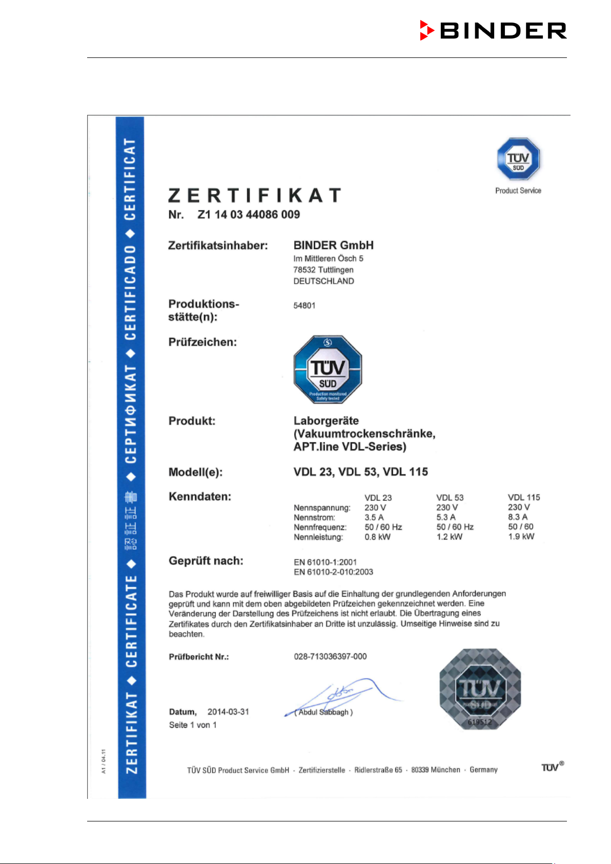
TÜV Certificate
VDL (E2.1) 04/2014 page 5/107
Page 6
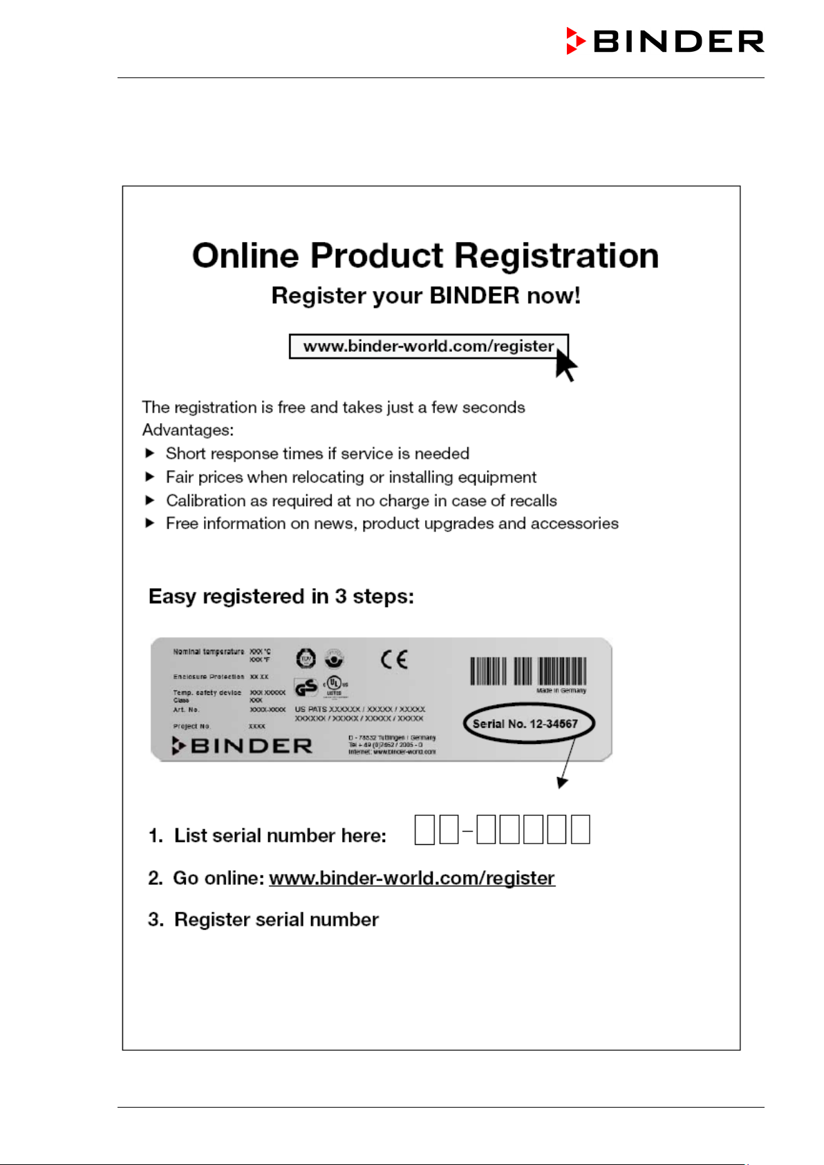
Product registration
VDL (E2.1) 04/2014 page 6/107
Page 7

Contents
EC – Declaration of Conformity ..................................................................................................................... 2
TÜV Certificate .............................................................................................................................................. 5
Product registration ....................................................................................................................................... 6
1. SAFETY ................................................................................................................ 10
1.1 Legal considerations ......................................................................................................................... 10
1.2 Structure of the safety instructions .................................................................................................... 10
1.2.1 Signal word panel .................................................................................................................... 10
1.2.2 Safety alert symbol .................................................................................................................. 11
1.2.3 Pictograms .............................................................................................................................. 11
1.2.4 Word message panel structure ............................................................................................... 12
1.3 Localization / position of safety labels on the unit ............................................................................. 12
1.4 Type plate .......................................................................................................................................... 13
1.5 General safety instructions on installing and operating the vacuum drying oven .............................. 14
1.5.1 Safety instructions on installation and ambient conditions ...................................................... 15
1.5.2 Safety instructions on vacuum supply ..................................................................................... 15
1.5.3 Safety instructions on the charging material ........................................................................... 17
1.5.4 Safety instructions on operating the vacuum drying oven ....................................................... 18
1.6 Intended use ...................................................................................................................................... 21
1.6.1 Operation log........................................................................................................................... 21
2. DESCRIPTION OF THE EQUIPMENT ................................................................. 23
2.1 Safety equipment .............................................................................................................................. 24
2.2 Overview of the oven ......................................................................................................................... 25
2.3 VDL control panel .............................................................................................................................. 26
2.4 Connections at the rear of the unit .................................................................................................... 27
2.5 “Temperature setting” information panel (ignition temperature vs. drying temperature) .................. 28
2.6 Overview of the zone classification of the ovens ............................................................................... 29
3. COMPLETENESS OF DELIVERY, TRANSPORTATION, STORAGE, AND
INSTALLATION .................................................................................................... 31
3.1 Unpacking, and checking equipment and completeness of delivery................................................. 31
3.2 Guidelines for safe lifting and transportation ..................................................................................... 32
3.3 Storage .............................................................................................................................................. 32
3.4 Location of installation and ambient conditions ................................................................................. 32
4. INSTALLATION AND CONNECTIONS ................................................................ 34
4.1 Vacuum expansion racks .................................................................................................................. 34
4.2 Vacuum connection ........................................................................................................................... 35
4.2.1 Notes regarding use of vacuum pumps of other manufacturers............................................. 37
4.3 Inert gas connection .......................................................................................................................... 37
4.4 Compressed air / inert gas connection for sweeping the area for electrical equipment .................... 38
4.5 Electrical connection ......................................................................................................................... 39
5. START UP ............................................................................................................ 40
5.1 Settings at the RD3 program controller ............................................................................................. 40
5.2 General indications ............................................................................................................................ 41
6. FIXED VALUE ENTRY MODE ............................................................................. 43
7. WEEK PROGRAM EDITOR ................................................................................. 45
7.1 Program table template for the Week Program Editor ...................................................................... 47
7.2 Programming example of the Week program editor ......................................................................... 48
7.2.1 Desired time function .............................................................................................................. 48
7.2.2 Proceeding overview ............................................................................................................... 48
7.2.3 Proceeding in detail ................................................................................................................. 49
VDL (E2.1) 04/2014 page 7/107
Page 8

8. PROGRAM EDITOR ............................................................................................. 54
8.1 Selecting between set-point ramp and set-point step ....................................................................... 54
8.1.1 Programming with setting “Ramp” (default setting) ................................................................ 54
8.1.2 Programming with setting “step” ............................................................................................. 57
8.1.3 General notes on programming temperature transitions ........................................................ 58
8.2 Set-point entry for program operation ............................................................................................... 58
8.3 Program table template ..................................................................................................................... 61
8.4 Deleting a program section ............................................................................................................... 62
9. PROGRAM START LEVEL .................................................................................. 63
10. USER LEVEL ....................................................................................................... 66
11. PERFORMANCE IN CASE OF FAILURES .......................................................... 72
11.1 Performance after power failures ...................................................................................................... 72
11.2 Alarm messages ............................................................................................................................... 72
12. SAFETY DEVICE CLASS 2 (DIN 12880) ............................................................. 72
13. REFERENCE MEASUREMENTS. CHECKING THE TEMPERATURE IN THE
INNER CHAMBER ................................................................................................ 74
14. COMMISSIONING THE VACUUM ....................................................................... 74
14.1 Evacuation ......................................................................................................................................... 75
14.2 Breaking the vacuum (flooding with ambient air) .............................................................................. 75
14.3 Operation with inert gas .................................................................................................................... 75
15. OPTIONS .............................................................................................................. 76
15.1 ATEX connection kits for vacuum pumps VP4 or VP5 (option) ........................................................ 76
15.2 Vacuum module empty (without pump) (option) ............................................................................... 77
15.3 Vacuum module with chemical membrane pump VP4 or VP5 (option) ............................................ 79
15.4 Additional measuring channel for digital object temperature display with flexible Pt 100 temperature
sensor (option) ..................................................................................................................................
15.5 Measuring access port vacuum 9 poles (option) ............................................................................... 84
15.6 Communication software APT-COM™ 3 DataControlSystem (option) ............................................. 84
82
16. MAINTENANCE, CLEANING, AND SERVICE ..................................................... 85
16.1 Maintenance intervals, service .......................................................................................................... 85
16.2 Cleaning and decontamination .......................................................................................................... 86
16.2.1 Cleaning .................................................................................................................................. 86
16.2.2 Decontamination ..................................................................................................................... 87
16.3 Sending the unit back to BINDER GmbH .......................................................................................... 89
17. DISPOSAL ............................................................................................................ 89
17.1 Disposal of the transport packing ...................................................................................................... 89
17.2 Decommissioning .............................................................................................................................. 90
17.3 Disposal of the unit in the Federal Republic of Germany .................................................................. 90
17.4 Disposal of the unit in the member states of the EC except for the Federal Republic of Germany .. 91
17.5 Disposal of the unit in non-member states of the EC ........................................................................ 93
18. TROUBLESHOOTING ......................................................................................... 93
19. TECHNICAL DESCRIPTION ................................................................................ 95
19.1 Factory calibration and adjustment ................................................................................................... 95
19.2 VDL technical data ............................................................................................................................ 95
19.3 Equipment and Options ..................................................................................................................... 97
VDL (E2.1) 04/2014 page 8/107
Page 9

Spare parts ........................................................................................................................................ 98
19.4
19.5 Dimensions VDL 23........................................................................................................................... 99
19.6 Dimensions VDL 53......................................................................................................................... 100
19.7 Dimensions VDL 115....................................................................................................................... 101
20. CONTAMINATION CLEARANCE CERTIFICATE .............................................. 102
20.1 For units located outside North America and Central America ....................................................... 102
20.2 For units in North America and Central America ............................................................................. 105
VDL (E2.1) 04/2014 page 9/107
Page 10
Dear customer,
For the correct operation of the program controlled vacuum drying oven VDL, it is important that you read
this operating manual completely and carefully and observe all instructions as indicated. Failure to read,
understand and follow the instructions may result in personal injury. It can also lead to damage to the unit
and/or poor equipment performance.
1. Safety
This operating manual is part of the components of delivery. Always keep it handy for reference. The device should only be operated by laboratory personnel especially trained for this purpose and familiar with
all precautionary measures required for working in a laboratory. Observe the national regulations on minimum age of laboratory personnel. To avoid injuries and damage observe the safety instructions of the
operating manual.
WARNING
Failure to observe the safety instructions.
Serious injuries and unit damage.
Observe the safety instructions in this operating manual.
Carefully read the complete operating instructions of the VDL vacuum drying oven.
1.1 Legal considerations
This operating manual is for informational purposes only. It contains information for installing, start-up,
operation and maintenance of the product. Note: the contents and the product described are subject to
change without notice.
Understanding and observing the instructions in this operating manual are prerequisites for hazard-free
use and safety during operation and maintenance. In no event shall BINDER be held liable for any damages, direct or incidental arising out of or related to the use of this manual.
This operating manual cannot cover all conceivable applications. If you would like additional information,
or if special problems arise that are not sufficiently addressed in this manual, please ask your dealer or
contact us directly by phone at the number located on page one of this manual
Furthermore, we emphasize that the contents of this operating manual are not part of an earlier or existing
agreement, description, or legal relationship, nor do they modify such a relationship. All obligations on the
part of BINDER derive from the respective purchase contract, which also contains the entire and exclusively valid statement of warranty administration. The statements in this manual neither augment nor restrict the contractual warranty provisions.
Have repairs performed only by experts authorized by BINDER. Repaired units must comply with the quality standard specified by BINDER.
1.2 Structure of the safety instructions
In this operating manual, the following safety definitions and symbols indicate dangerous situations following the harmonization of ISO 3864-2 and ANSI Z535.6.
1.2.1 Signal word panel
Depending on the probability of serious consequences, potential dangers are identified with a signal word,
the corresponding safety color, and if appropriate, the safety alert symbol.
VDL (E2.1) 04/2014 page 10/107
Page 11
Warning signs
Electrical hazard
Hot surface
or chemical burns
DANGER
Indicates an imminently hazardous situation that, if not avoided, will result in death or serious (irreversible) injury.
WARNING
Indicates a potentially hazardous situation which, if not avoided, could result in death or serious (irreversible) injury.
CAUTION
Indicates a potentially hazardous situation which, if not avoided, may result in moderate or minor (reversible) injury.
CAUTION
Indicates a potentially hazardous situation, which, if not avoided, may result in damage to the product
and/or its functions or to property in its proximity.
1.2.2 Safety alert symbol
Use of the safety alert symbol indicates a risk of injury.
Observe all measures that are marked with the safety alert symbol in order to avoid death or
injury.
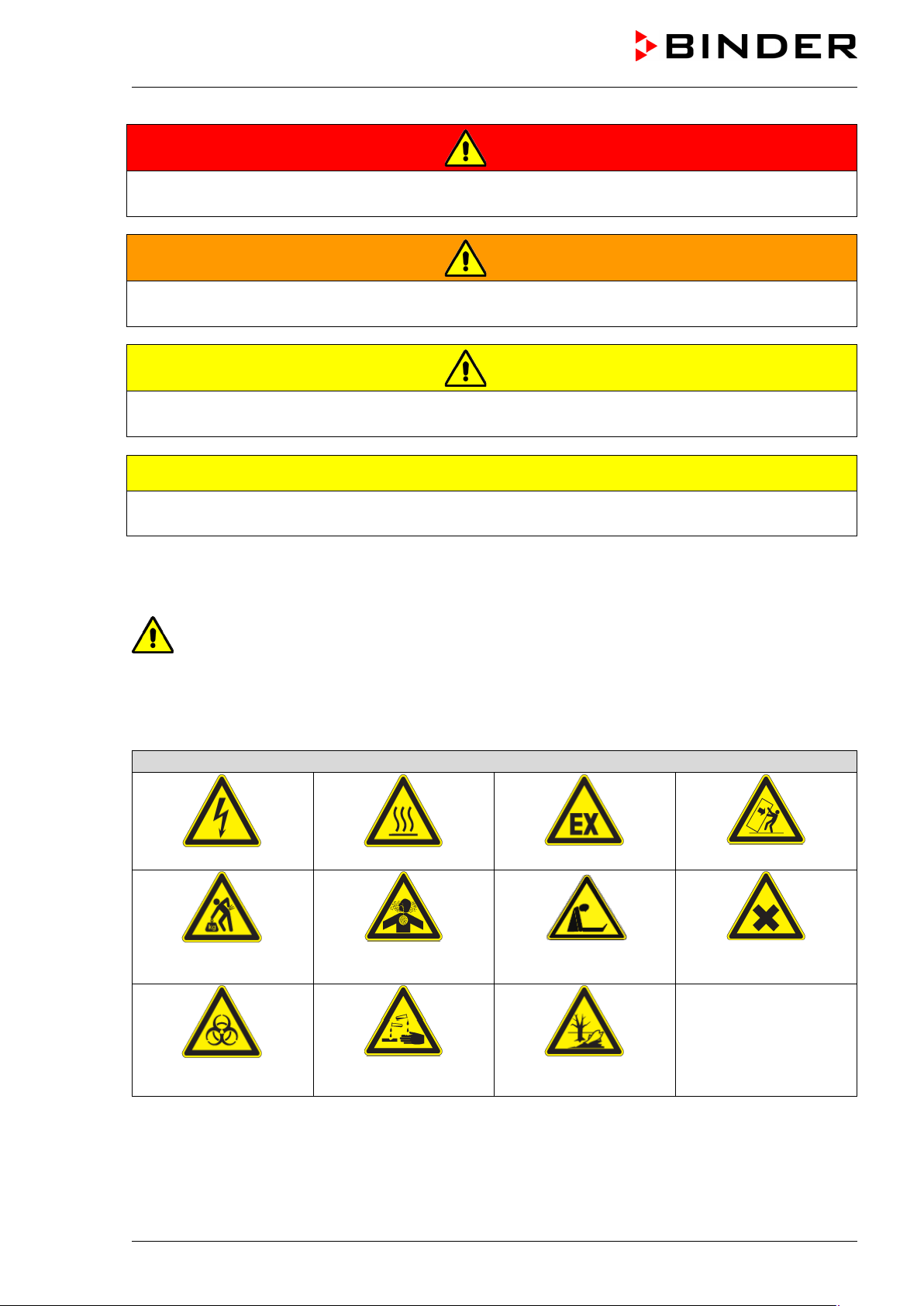
1.2.3 Pictograms
Lifting hazard
Inhalation hazard
Explosive atmosphere
Suffocation hazard
Stability hazard
Harmful substances
Biohazard
VDL (E2.1) 04/2014 page 11/107
Risk of corrosion and /
Pollution Hazard
Page 12
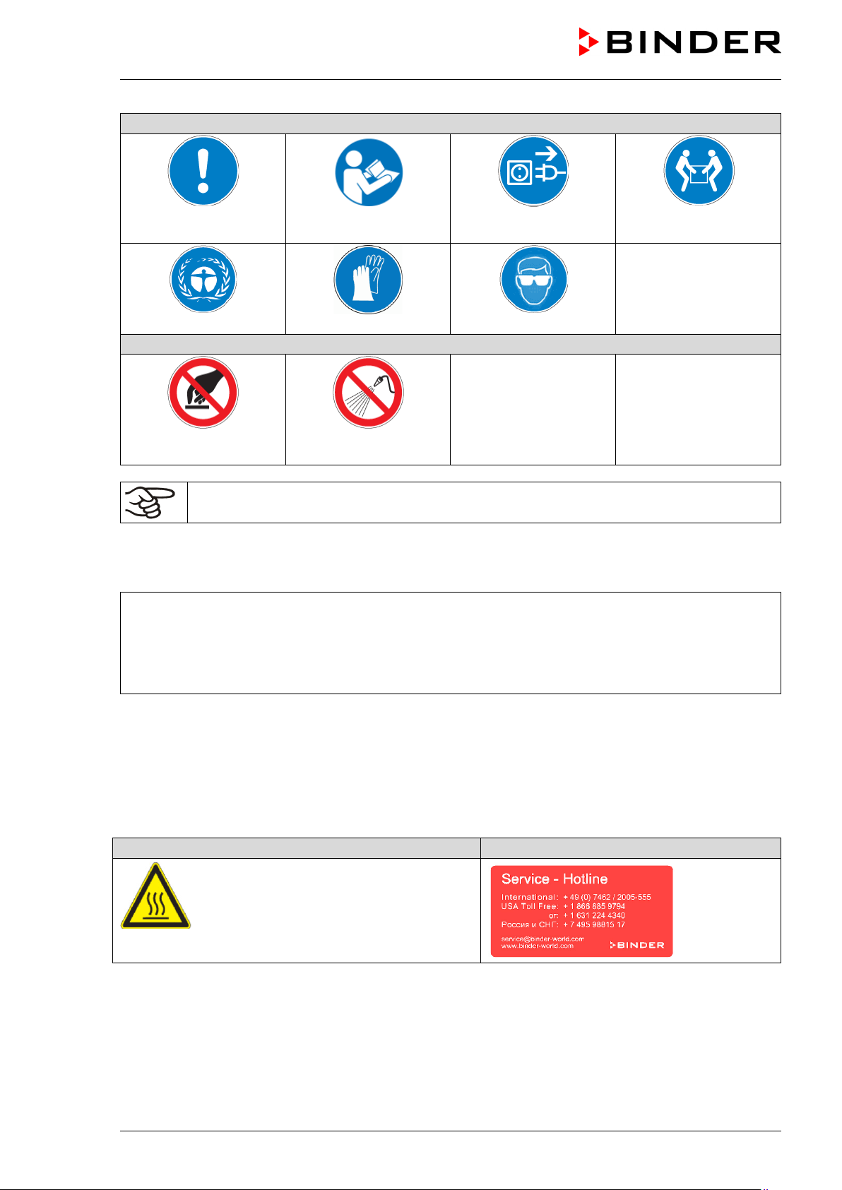
Mandatory action signs
plug
Wear protective gloves
Prohibition signs
water
Pictograms (Warning signs)
Service label
Mandatory regulation
Environment protection
Do NOT touch
Information to be observed in order to ensure optimum function of the product.
Read operating
instructions
Do NOT spray with
1.2.4 Word message panel structure
Type / cause of hazard.
Disconnect the power
Wear eye protectors
Lift with several persons
Possible consequences.
∅ Instruction how to avoid the hazard: prohibition
Instruction how to avoid the hazard: mandatory action
Observe all other notes and information not necessarily emphasized in the same way, in order to avoid
disruptions that could result in direct or indirect injury or property damage.
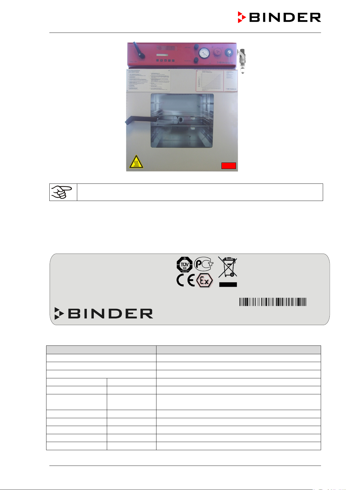
1.3 Localization / position of safety labels on the unit
The following labels are located on the unit:
Hot surface
VDL (E2.1) 04/2014 page 12/107
Page 13
Indications of the type plate
Information
BINDER
Manufacturer: BINDER GmbH
VDL 53
Model VDL 53
Vacuum Drying Oven
Vacuum drying oven
Serial No.
00-00000
Serial No. 00-00000
Built
2014
Year of construction: 2014 (example))
392°F
Enclosure protection
IP 54
IP type of protection 54 acc. to EN 60529
Temp. safety device
DIN 12880
Temperature safety device acc. to standard DIN 12880
Class
2.0
Temperature safety device, class 2
Art. No.
9030-0039
Art. No. 9030-0039
Project No.
---
(Special application acc. to project no.)
Nominal temperature
200 °C
1,20 kW
EXPLOSION PROOF INNER CHAMBER
392 °F
230 V 1 N ~
EX CLASSIFICATION ACC. TO 94/9/EC
Temp. safety device
IP
DIN 12880
50/60 Hz
MAX. TEMP. OF INNER SURFACE +320 °C
Class
2.0 TEMP. CLASS DEPENDING ON
Art. No.
9030-0039
Max. operating pressure 125 +/- 25 mbar
SETTING OF TEMP. SAFETY DEVICE
Project No.
Built
2014
US PATENT 5405194
Vacuum Drying Oven
D 78532 Tuttlingen / Germany
Internet: www.binder-world.com
VDL 53 Serial No. 00-00000
E2.1 Made in Germany
Figure 1: Position of labels on the unit
Keep safety labels complete and legible.
Replace safety labels that are no longer legible. Contact BINDER Service for these replacements.
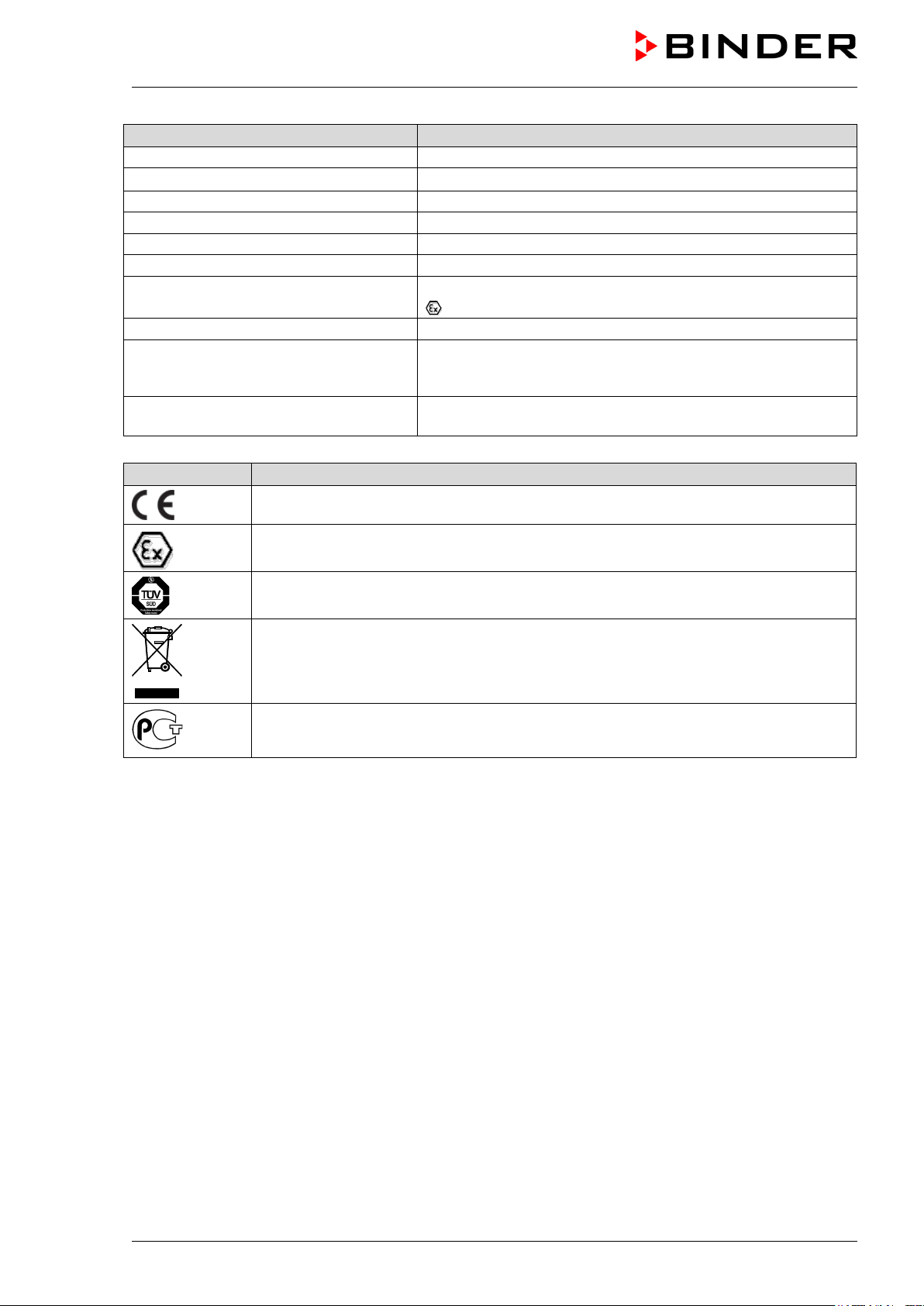
1.4 Type plate
Position of type plate: left unit side (seen from front), at the bottom right-hand.
Enclosure protection
54
5,3 A
Tel. + 49 (0) 7462/ 2005-0
Figure 2: Type plate (example of VDL 53 regular unit)
II -3G IIB T3-T1 Gc X
Nominal temperature
200 °C
VDL (E2.1) 04/2014 page 13/107
Nominal temperature
Page 14
Indications of the type plate
Information
1,20 kW
Nominal power 1.20 kW
230 V 1 N ~
Nominal voltage 230 V ± 10%, single-phase unit
5,3 A
Nominal current 5.3 Amp
50/60 Hz
Power frequency 50/60 Hz
Explosion proof inner chamber
Explosion proof inner chamber
Ex classification acc. to 94/9/EC
Ex classification according to ATEX Directive 94/9/EC
Ex classification of the inner chamber:
II -3G IIB T3-T1 Gc X
Max. temp. of inner surface 320 °C
Maximum temperature of the inner surfaces: 320 °C / 608°F
Temperature class acc. to IEC 60079-14 for entire unit: T1,
device
Max. operating pressure 125 +/- 25
mbar
Symbol
Information
II -3G IIB T3-T1 Gc X
Temp. class depending on setting of
temp. safety device
Ex classification acc. to ATEX Directive 94/9/EC, referring to the inner chamber
CE conformity marking
TÜV mark of conformity (Mark P)
Electrical and electronic equipment manufactured / placed on the market in the EC
after 13 August 2005 and to be disposed of in a separate collection according to directive 2002/96/EC on waste electrical and electronic equipment (WEEE).
The equipment is certified in the GOST R certification system of GOSTSTANDARD
Russia.
T2 or T3 depending on the setting of the temperature safety
Max. operating pressure (heating release): 125 +/- 25 mbar
1.5 General safety instructions on installing and operating the vacuum drying
oven
With regard to operating the vacuum drying oven VDL and to the installation location, please observe the
guideline BGI/GUV-I 850-0 on safe working in laboratories (formerly BGR/GUV-R 120 or ZH 1/119 laboratory guidelines issued by the employers’ liability insurance association) (for Germany).
BINDER GmbH is only responsible for the safety features of the unit provided skilled electricians or qualified personnel authorized by BINDER perform all maintenance and repair, and if components relating to
chamber safety are replaced in the event of failure with original spare parts.
To operate the unit, use only original BINDER accessories or accessories from third-party suppliers authorized by BINDER. The user is responsible for any risk caused by using unauthorized accessories.
VDL (E2.1) 04/2014 page 14/107
Page 15
1.5.1 Safety instructions on installation and ambient conditions
Familiarize yourself with the local conditions, particularly allocation to a defined potentially explosive area
(zones) and the relevant technical safety requirements. During installation, commissioning and operation
of the vacuum drying oven and the connected vacuum pump or in-house vacuum supply, always follow
the requirements defined by the installation site.
CAUTION
Danger of overheating.
Damage to the unit.
∅ Do NOT install the oven in unventilated recesses.
Ensure sufficient ventilation for dispersal of the heat.
Do not operate the vacuum drying oven VDL in hazardous locations.
DANGER
Explosion hazard.
Danger of death.
∅ Do NOT operate the unit in potentially explosive areas.
KEEP explosive dust or air-solvent mixtures AWAY from the unit.
The vacuum drying ovens were constructed in accordance with the applicable VDE regulations and were
routinely tested in accordance with VDE 0411-1 (IEC 61010-1). The production underlies an internal monitoring according to ATEX Directive 94/9/EC appendix VIII.
Even when the equipment is used properly, there exists a residual risk of explosion that cannot be excluded, particularly in relation to the environment of the unit. To minimize this risk, strictly observe the legal
regulations about how to select an appropriate location.
DANGER
Explosion hazard.
Danger of death.
Strictly observe the legal regulations about how to select an appropriate location.
1.5.2 Safety instructions on vacuum supply
Pertaining to units that will be operated in potentially explosive areas, the requirements of ATEX Directive
94/9/EC have to be met as of July 1, 2003.
If combustible solvent is introduced into the drying chamber, the vacuum pump must be constructed in a
suitable explosion-proof manner.
Observe the safety instructions of the pump manufacturer.
The mixtures extracted from the inner chamber must be carried away making sure that there is no danger
by ignition of these atmospheres. Otherwise, use flame arresters (flame flash-through barrier). For installing a flame arrester, please contact the BINDER INDIVIDUAL team.
In case of an explosion, the flame can be suctioned into an in-house vacuum system thereby resulting in
further explosions.
VDL (E2.1) 04/2014 page 15/107
Page 16
DANGER
Danger due to flame flash-through with in-house vacuum system.
Danger of death.
We recommend installing a flame arrester (flame flash-through barrier) according to EN
12874 between the VDL vacuum drying oven and the in-house vacuum system.
Sparking in the pump motor or the switching elements, electrostatic discharges, as well as hot pump parts
can ignite solvent vapors in the event of an error. To minimize this risk, use an ATEX (Directive 94/9/EC)
compliant vacuum pump suitable for suction from Zone 0 or 1 and, if appropriate, from the zone of its
installation site.
DANGER
Ignition of emerging solvent vapors due to sparking in the pump motor or the
switching elements, electrostatic discharges, hot pump parts.
Explosion hazard.
Danger of death.
Use only suitable, explosion-proof pumps
Operate the pump in a stationary position and secure it so it is immobile.
Install a fixed and conductive suction line to the vacuum connection (13).
Install a fixed and conductive exhaust pipe in case it may conduct ignitable solvent con-
centrations. This should be avoided by sufficient solvent condensation e.g., in an exhaust waste vapor condenser
When using ATEX (Directive 94/9/EC) non-compliant pumps: Provide a current-
dependent, delayed protective device for the pump (for the triggering time of this protective device, see the manufacturer’s specifications). The protective and monitoring device must not be able to turn on independently again or be released.
When using ATEX (Directive 94/9/EC) non-compliant pumps: Install the switch gear box
outside the hazardous area or provide it with explosion protection.
Assure equipotential bonding between the pump housing and the housing of the VDL
vacuum drying oven by the connected equipment grounding conductors of both units.
The ATEX (Directive 94/9/EC) compliant pumps offered by BINDER provide an integral protective device.
The ATEX (Directive 94/9/EC) compliant pumps offered by BINDER provide an integral explosion proof switch.
Confirm that the vacuum source is designed for a gas inlet temperature corresponding to the
used drying temperature, or take appropriate measures to cool down the extracted vapor before it enters the vacuum source.
VDL (E2.1) 04/2014 page 16/107
Page 17
The ATEX (Directive 94/9/EC) compliant vacuum pumps offered by BINDER are designed for a gas
inlet temperature of 40 °C / 104°F max. Do NOT exceed this temperature. If the gas inlet temperature is
too high and then becomes even warmer by compression in the pump, the resulting temperature (of the
gas-solvent mixture inside the pump) could exceed the solvent’s temperature class and ignition temperature.
DANGER
Exceeding the gas inlet temperature.
Exceeding the ignition temperature of the solvent.
Risk of ignition and explosion.
Damage to the vacuum pump.
Danger of death.
∅ Do NOT exceed a set-point temperature of 40 °C / 104 °F.
With set-point temperature > 40 °C / 104 °F, take appropriate measures to cool down
the extracted vapor before it enters into to the vacuum pump.
1.5.3 Safety instructions on the charging material
The temperature class of the inner chamber according to IEC 60079-14 can be T1, T2, or T3. Only introduce substances with an ignition temperature that is higher than 135 °C / 275°F. You can use a solvent
which would form an explosive mixture with air under normal conditions.
This unit is not suitable to dry substances with an ignition temperature below 135 °C / 275°F. Substances
falling under ignition group IIC are not permitted (e.g. carbon disulfide, hydrogen).
DANGER
Inappropriate charging material.
Explosion hazard.
Danger of death.
∅ Do NOT introduce any substance with an ignition temperature below 135 °C / 275 °F
into the oven.
∅ Do NOT introduce hazardous dusts or fibrous materials, which tend towards exothermal
decomposition into the oven.
∅ Do NOT introduce materials that come under the explosive substance law into the oven.
If the ignition temperature of a solvent contained in the drying material is exceeded during the drying process, there is an immediate risk of fire and explosion.
DANGER
Formation of explosive solvent-air mixtures.
Fire and explosion hazard.
Danger of death.
∅ The ignition temperature of the contained solvents must NEVER be reached. For safety
reasons, you must provide a safety gap.
VDL (E2.1) 04/2014 page 17/107
Page 18
chap.
During the drying process, use only those solvents for which the temperature setting has
h the lowest
ignition temperature, refer to the safety specifications
ed use, an explosive mixture may form in the working space. Define a safety area of at
If the following precautions are not followed, the vapors resulting from heating of the solvent can ignite on
the hot walls of the inner chamber.
Required measures:
• The maximum drying temperature is a result of the lowest ignition temperature of the introduced solvent or solvent mixture. Take the ignition temperature from the safety specifications of the solvent. Determine the maximum drying temperature according to the information panel “Temperature setting” (chap. 2.5) on the unit front. Do NOT exceed this temperature when presetting the set point on the RD3 temperature controller.
• Before starting the drying process, set the temperature safety device to the maximum allowed drying temperature according to the information panel “Temperature setting” (
2.5). This will ensure that even in the event of error or an incorrect increase of the temperature set point on the RD3 controller the maximum permissible drying temperature is not exceeded. It is NOT sufficient to directly adjust the maximum temperature of the temperature
safety device to the maximum temperature of the solvent’s temperature class.
•
been performed.
• In the case of solvent mixtures, use the ignition temperature of the material wit
ignition temperature. For the correct
of the solvent.
• Let the oven cool down to ambient temperature before you start a new drying process with
a modified ignition temperature.
Familiarize yourself with the physical and chemical properties of the charging material, as well as the contained moisture constituent and its behavior with the addition of heat energy and changes in pressure.
No dangerous chemical reactions must occur during the drying process.
Familiarize yourself with any potential health risks caused by the charging material, the contained moisture
constituent or by reaction products that may arise during the drying process. Take adequate measures to
exclude such risks prior to putting the VDL vacuum drying oven into operation.
1.5.4 Safety instructions on operating the vacuum drying oven
Note the following points before starting up the oven:
• When loading the unit and possibly at the moment of removal, also in the context of intend-
least 1m from the unit front.
• Ensure that at no time any solvent vapors could enter in the area of the electrical installation
room and the operating panel.
• Provide additional security measures in the area of the vacuum pump stand, particularly in
the areas of the glass flask (when emptying it) and the exhaust air of the vacuum pump.
• The accessible area in front of the equipment must be designed conductive. Provided cyclic
measurements.
• The personal protective equipment (PPE) of the operating personnel must be implemented
ESD protected.
VDL (E2.1) 04/2014 page 18/107
Page 19
upply: Close
DANGER
Electrical hazard.
Danger of death.
∅ The oven must NOT become wet during operation or maintenance.
CAUTION
The inner chamber will become hot during operation.
Danger of burning.
∅ Do NOT touch the inner surfaces or the charging material during operation.
When operating the VDL vacuum drying oven with inert gas, correctly follow the technical ventilation
measures, as described in the guideline BGI/GUV-I 850-0 on safe working in laboratories (formerly
BGR/GUV-R 120 or ZH 1/119 laboratory guidelines issued by the employers’ liability insurance association) (for Germany).
Do not start up the unit without technical ventilation.
During operation with inert gas, the unit is supplied with an oxygen displacing gas (e.g. N
high concentrations are hazardous to health. They are colorless and almost odorless and therefore practically imperceptible. Inhalation of inert gases can cause drowsiness up to respiratory arrest. When the O
content of the air decreases below 18%, there is risk of death from lack of oxygen. Any gas that might
escape has to be led out via good room ventilation or a suitable exhaust system.
). Inert gases in
2
WARNING
High concentration of inert gas.
Risk of death by suffocation.
∅ Do NOT set up units in non-ventilated recesses.
Ensure technical ventilation measures.
Respect the relevant regulations for handling these gases.
When decommissioning the vacuum drying oven, shut off the inert gas s
valve (6).
If solvent-containing air penetrates the electrical area of the oven, explosions may result.
DANGER
2
Solvent-containing air penetrating the electrical area of the oven.
Explosion hazard.
∅ Do NOT take the air, which will be used to supply the unit with compressed air, from a
potentially explosive atmosphere.
Avoid the solvent accumulation in the vacuum module (option) as this would cause the vacuum
module to become an explosive area (Zone 0 or 1 or 2). The VDL vacuum drying oven located
on top of the module is not explosion-proof constructed in regards to its surroundings.
VDL (E2.1) 04/2014 page 19/107
Page 20
for at least 15
drying temperature in relation to the ignition temperature of the
with the lowest
and remove the key
at least 15 minutes with compressed air or inert
emperature before you start a new drying process with
a modified ignition temperature.
DANGER
Operation with material containing solvent that may be able to form an explosive
mixture with air.
Explosion hazard.
Follow the measures required for operation with solvent-containing materials that can
form an explosive mixture with air.
Measures required for operation with solvent-containing materials that can form an explosive
mixture with air:
• Only trained personnel with key-authorization can work on the VDL vacuum drying oven
• Sweep the area for electrical equipment with compressed air or inert gas
minutes. Sweeping must take place during the entire operating cycle; otherwise the vacuum
drying oven will shut off at all poles.
• Only after at least 15 minutes of sweeping, use the key switch to put the unit in operation.
• Determine the maximum
solvent according to the information panel “Temperature setting” (chap. 2.5). Do NOT exceed this temperature when presetting the set point on the RD3 temperature controller.
• In the case of solvent mixtures, use the ignition temperature of the solvent
ignition temperature. For the ignition temperature, refer to the safety specifications of the
solvent.
• Before starting the drying process, set the temperature safety device to the maximum allowed drying temperature according to the information panel “Temperature setting” (chap.
2.5). It is NOT sufficient to directly adjust the maximum temperature of the temperature
safety device to the maximum temperature of the solvent’s temperature class.
• Introduce the drying material and turn on the vacuum pump.
• Start the drying process. The heating unit is only released when a vacuum of 125 ± 25 mbar
/ 3.69 ±0.74 inHg) or below is reached.
• The duration of the drying process can be determined by means of the analogue pressure
display on the oven. When the pressure drops to pump pressure, the drying process is finished.
• Stop the drying process.
• Ventilate the vacuum drying oven using the aeration valve for ambient air (5) or inert gas
(6).
• Remove the charging material. Turn the key switch to position 0 (OFF)
to prevent unauthorized operation of the oven.
• Sweep the area for electrical equipment
gas.
• Let the oven cool down to ambient t
VDL (E2.1) 04/2014 page 20/107
Page 21
1.6 Intended use
The VDL vacuum drying ovens are suitable for drying and heat treatment of solid or pulverized charging
material, as well as bulk material, using the supply of heat under vacuum.
During this process, the contained solvent may be able to form an explosive mixture with air under normal
conditions. Generation of an explosive atmosphere and its ignition are prevented in the VDL vacuum drying ovens by various safety measures. The drying temperature with standard safety factor must lie below
the ignition temperature and below the sublimation point of the charging material.
The temperature class of the inner chamber according to IEC 60079-14 can be T1, T2, or T3. Insert only
substances with an ignition temperature that is higher than 135 °C / 275°F. The unit is not suitable to dry
substances with an ignition temperature below 135 °C / 275°F. Substances falling under ignition group IIC
are not permitted (e.g. carbon disulfide, hydrogen).
The VDL vacuum drying ovens are NOT suitable for the heat treatment of hazardous dusts or fibrous materials, which tend towards exothermal decomposition, or for materials that come under the legal definition
of explosives. Dangerous chemical reactions must not occur during the drying process.
Following the instructions in this operating manual and conducting regular maintenance work
(chap. 16) are part of the intended use.
The charging material shall not contain any corrosive ingredients that may damage the machine components made of stainless steel and aluminum. Such ingredients include in particular acids and halides. Any corrosive damage caused by such ingredients is excluded from liability by BINDER GmbH.
1.6.1 Operation log
For safety reasons, keep an operation log.
The following contents must be entered and recorded:
• Type of solvent
• Ignition temperature
• Set temperature
• Set safety device
• Date
• Signature
Use the following page as a specimen or compile it in a suitable form.
VDL (E2.1) 04/2014 page 21/107
Page 22
Max. tempera-
device
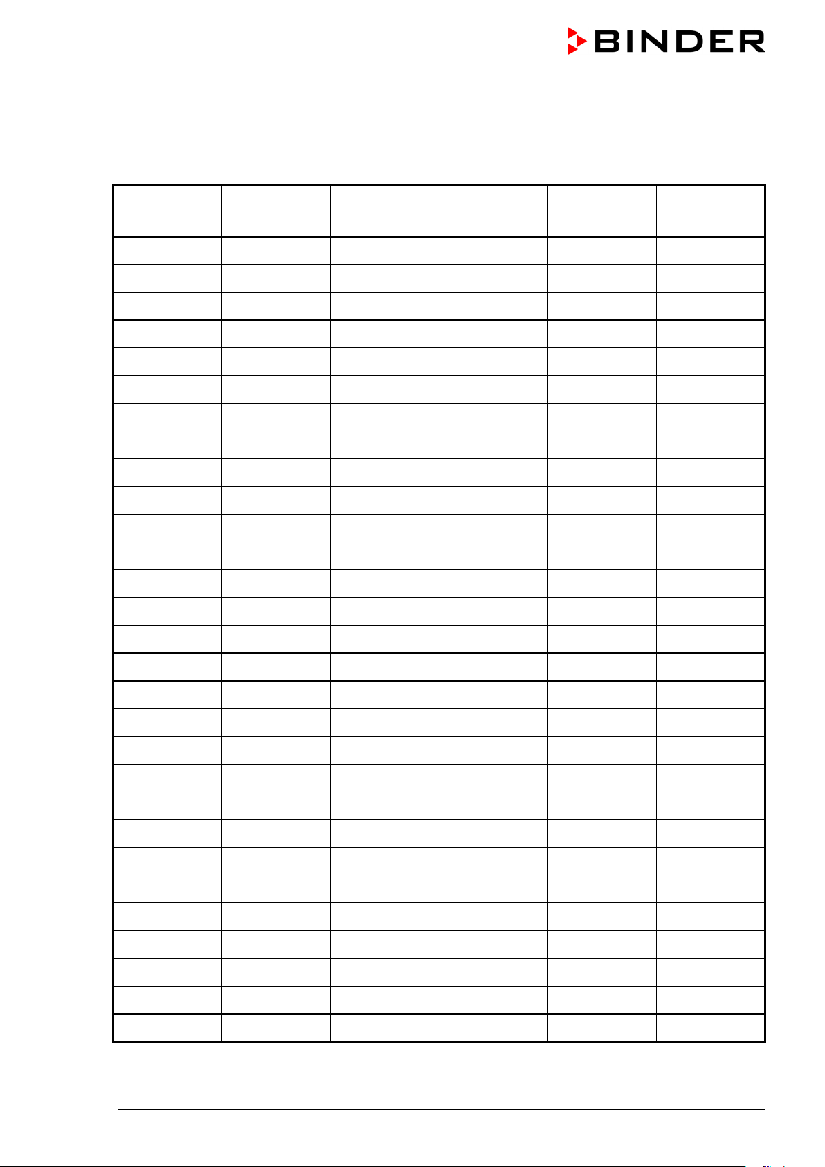
Operation log for the VDL vacuum drying oven
Serial number...............................................
Solvent
Ignition temper-
ature
Set drying tem-
perature
ture of safety
Date Signature
VDL (E2.1) 04/2014 page 22/107
Page 23

2. Description of the equipment
The VDL vacuum drying oven has been inspected by the TÜV Product Service GmbH in accordance with
all safety-relevant guidelines and bears the TÜV-Mark P mark. Consequently, it is also expressly approved for drying materials with unlimited quantities of organic solvents.
The regular model is equipped with an explosion proof inner chamber. The Ex classification of inner
chamber according to ATEX Directive 94/9/EC is
protection on the type plate determines the classification.
Maximum temperature of the inner surfaces: 320 °C / 608°F.
The temperature class of the inner chamber acc. to IEC 60079-14: depends on the setting of the tempera-
ture safety device and can be T1, T2 or T3. The temperature class of the entire unit equals the temperature class of the inner chamber.
All functions of the multifunctional program control can be set simply and conveniently via the easy to understand function keypad of the RD3 temperature program controller. This controller is equipped with
touch function keys and a digital display and permits exact temperature setting and programming temperature cycles. The VDL provides almost unlimited possibilities of adapting to individual customer requirements based upon extensive programming options and on the week program timer and real time clock of
the controller.
II -3G IIB T3-T1 Gc X. The description of explosion
The inner chamber is made of especially corrosion resistant stainless steel V4A (German material no.
1.4404 2B, US equivalent AISI 316L) micro-polished. The rack holder and all of the unit's vacuum connections and valves are made of especially corrosion resistant stainless steel V4A (German material no.
1.4571, US equivalent AISI 316Ti). The housing is RAL 7035 powder-coated. All corners and edges are
also completely coated. When operating the chamber at temperatures above 150 °C / 302°F, the impact
of the oxygen in the air may cause discoloration of the metallic surfaces (yellowish-brown or blue) by natural oxidation processes. These colorations are harmless and will in no way impair the function or quality of
the unit.
The vacuum drying ovens in the APT.line™ are jacket-heated. The APT.line™ preheating chamber technique ensures a completely homogeneous jacket temperature, ensuring uniform heat transfer into the
inner chamber. The low-loss heat transfer to the material uses the patented aluminum vacuum expansion
racks (or optionally available in stainless steel V4A, 1.4571). The elastic-mounted safety glass window
reliably compensates any overpressure or explosions that may occur. The additional polycarbonate panel
ensures proven and effective splinter protection in the event of an implosion.
All VDL units provide an inert gas connection, a compressed air connection for sweeping the area for
electrical equipment, and a measuring connection serving to connect a measuring access port.
The VDL vacuum drying oven is equipped with a serial interface RS 422 for computer communication, e.g.
via the communication software APT-COM™ 3 DataControlSystem (option, chap.15.6). For further options, see chap. 19.3.
All installable items, such as racks and rack holders, can be easily removed. The completely smooth inner
chamber with its rounded corners and internally welded seams is easy to clean.
The minimum working temperature of the VDL vacuum drying oven is approx. 15 °C / 27 °F above room
temperature. The maximum temperature is 200 °C / 392°F.
3
Vacuum pumps with a suction capacity of 1 m
The permissible end vacuum is 10
-2
mbar / 0.0003 inHg.
/h to 30 m3/h are suitable for the VDL vacuum drying oven.
VDL (E2.1) 04/2014 page 23/107
Page 24
The VDL vacuum drying oven is equipped with a
The inspection window, consisting of ESG glass
d and
serves as a safety valve in the event of explosion.
2.1 Safety equipment
• Pressure control device
The VDL vacuum drying oven is equipped with a pressure control device with atmospheric pressure
compensation and has a set switch point of 125 ± 25 mbar / 3.69 ± 0.74 inHg). In the event of malfunction, some procedures would become an ignition source. Due to monitoring by the pressure control device such actions will only initiate if the pressure in the drying chamber is not higher than 125 ± 25
mbar / 3.69 ± 0.74 inHg.
The heating is released when a vacuum of 125 ± 25 mbar / 3.69 ± 0.74 inHg) or below is
obtained. It will activate only then.
• Safety device class 2
This safety device protects the VDL vacuum drying oven, its environment and the charging material
against impermissible excess temperatures. When correctly set to the maximum permissible drying
temperature it prevents exceeding the maximum drying temperature in case of a fault (chap. 12).
• Sweeping the area for electrical equipment and the preheating chamber with compressed air
The area for electrical equipment and the preheating chamber are protected against explosion by a
technical ventilation system, which reliably prevents the penetration of explosive atmosphere to electrical or electronic parts of the VDL safety vacuum drying oven (protection against solvent-containing
ambient air).
• Flame protection gasket
In case of an explosion, the flame protection gasket prevents any flames from emerging directly
through the door gap..
• Spring-mounted safety glass panel and splinter protection
large-surface area safety valve.
(toughened safety glass), is spring-mounte
The additional plastic panel provides splinterprotection.
Figure 3: Safety glass panel
VDL (E2.1) 04/2014 page 24/107
Page 25
(A)
(B)
(C)
(D)
(E)
(F)
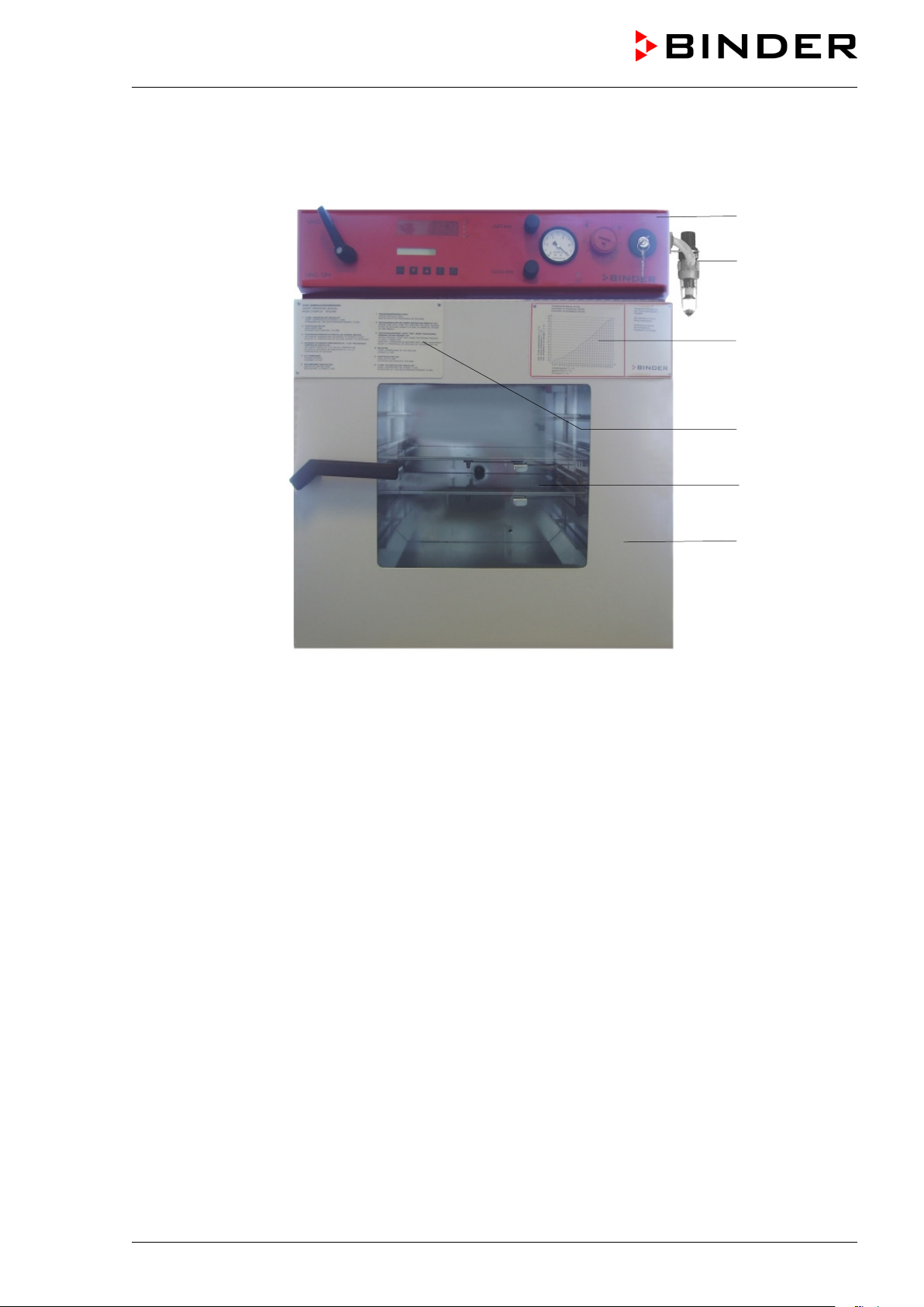
2.2 Overview of the oven
Figure 4: VDL 53
(A) Area for electrical equipment swept with compressed air, and control panel
(B) Compressed air connection
(C) Information panel “Temperature setting”
(D) Information panel short description
(E) Spring-mounted safety glass window
(F) Unit door
VDL (E2.1) 04/2014 page 25/107
Page 26
AIR
GAS
VAC.OFF
VAC.ON
AIR
GAS
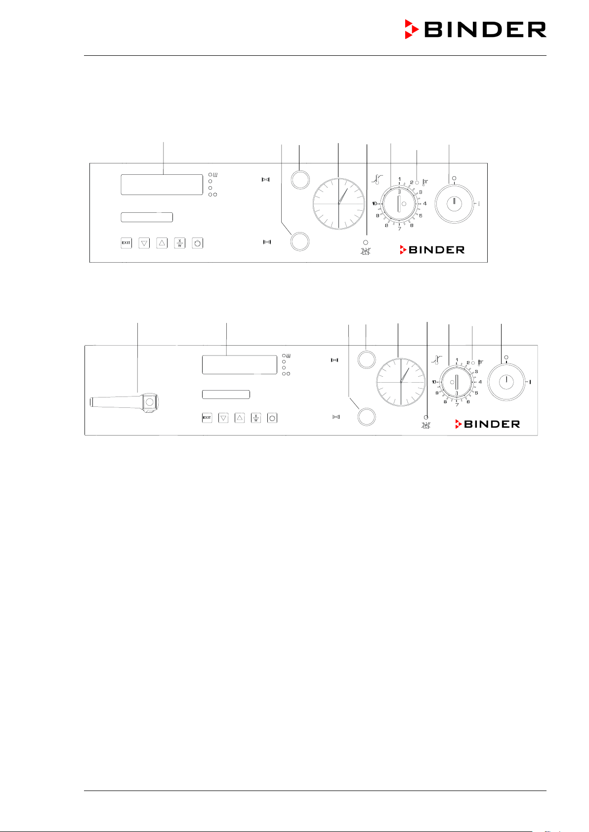
2.3 VDL control panel
(7) (6) (5) (3) (4) (2) (2a) (1)
Figure 5: VDL 23 control panel
(8) (7) (6) (5) (3) (4) (2) (2a) (1)
Figure 6: VDL 53/115 control panel
(1) Key switch (main power switch)
(2) Temperature safety device class 2
(2a) Red alarm lamp of the safety device class 2
(3) Manometer (pressure reading)
(4) Yellow pilot light: No heating release
(5) Aeration valve (ambient air)
(6) Fine dosing valve (inert gas)
(7) Program controller RD3
(8) Vacuum shut-off valve
VDL (E2.1) 04/2014 page 26/107
Page 27
(10) (14) (13) (9)
(10) (11) (12) (14) (13) (9)
(8) Vacuum shut-off valve
(11) (8) (12)
VAC.OFF
VAC.ON
GAS
AIR
(15)
(15)
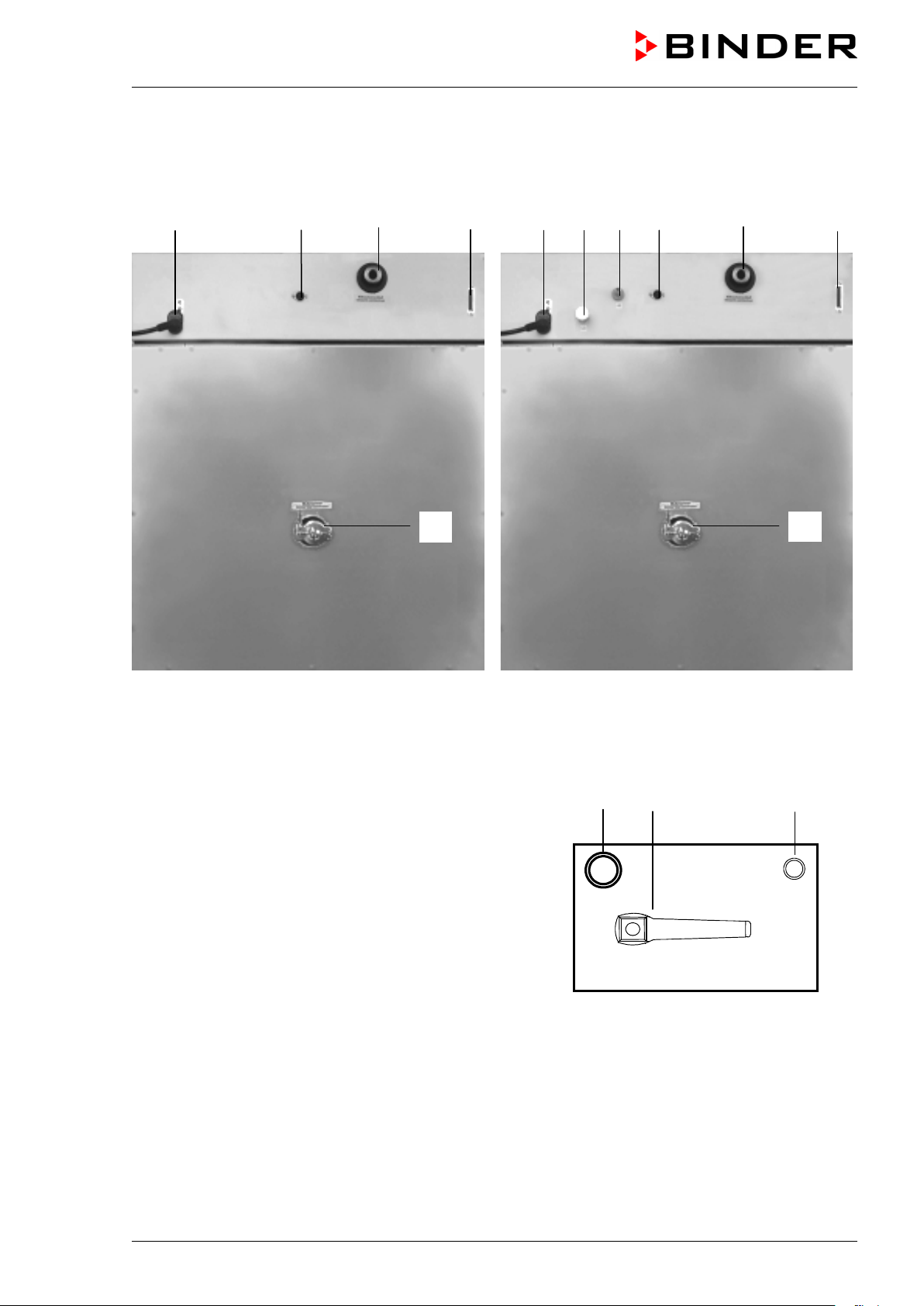
2.4 Connections at the rear of the unit
VDL 23
(9) RS 422 serial interface for computer communication
(10) Power connection line
(11) Inert gas connection, adapter with hose olive
∅ 8 mm / 0.31 in
(12) Fresh air connection (tube 8x1 mm)
(13) Vacuum connection with small flange DN16
(14) DIN socket “Object-Pt100“ (option) to connect a Pt 100
sensor (with option “object temperature display”)
(15) Measuring connection with small flange DN16
VDL 53 / VDL 115
Figure 7: Rear of VDL
Figure 8: Connections left side VDL 23
VDL (E2.1) 04/2014 page 27/107
Page 28
vacuum drying
The reading graph reflects the fact
come warmer than the expansion
Temperatureinstellung VDL
drying temperature in relation to the ignition temperature of the
point on
(continued)
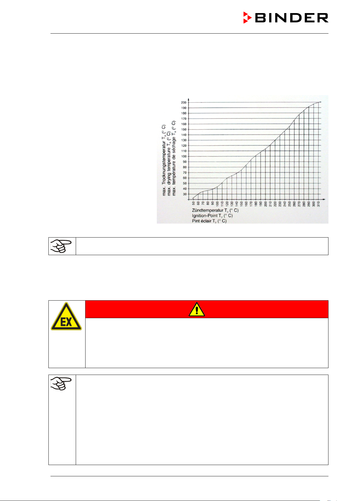
2.5 “Temperature setting” information panel
(ignition temperature vs. drying temperature)
Adjustment of temperature VDL
This information panel is mounted to
the door of the VDL
oven and shows the maximum permissible drying temperature depending on the ignition temperature of the
solvent.
that the inner chamber walls will be-
racks, especially during the heatingup phase, and will thereby exceed the
set-point temperature.
Ajustement de température VDL
You must observe the indicated safety margin between ignition temperature and drying temperature.
According to IEC 60079-14, you must introduce only substances with an ignition temperature which is
higher than 135 °C / 275°F. This unit is NOT suitable to dry substances with an ignition temperature
below 135 °C / 275°F.
If the ignition temperature of a solvent contained in the drying material is exceeded during the drying process, there is an immediate risk of fire and explosion.
Exceeding the ignition temperature of a solvent.
Risk of fire and explosion.
Danger of death.
∅ The ignition temperature of a contained solvent must NEVER be reached. For safety
reasons, always ensure that there is a safety margin.
Required measures:
• Determine the maximum
solvent in accordance with the “Temperature setting” information panel (chap. 2.5). Do NOT
exceed this temperature when presetting the set-point temperature at the temperature controller RD3.
• Before starting the drying process, set the temperature safety device to the allowed maximum drying temperature according to the information panel “temperature setting” chap.
2.5), so that even in the event of error or incorrect increase of the temperature setthe RD3 controller the maximum permissible drying temperature is not exceeded. It is NOT
sufficient to directly adjust the maximum temperature of the temperature safety device to
the maximum temperature of the solvent’s temperature class.
•
Figure 9: Temperature setting information panel
DANGER
VDL (E2.1) 04/2014 page 28/107
Page 29
r which the temperature setting has
oven cool down to ambient temperature before you start a new drying process with
a modified ignition temperature.
Required measures (continuation):
• During the drying process, use only those solvents fo
been performed.
• In the case of solvent mixtures, use the ignition temperature of the material with the lowest
ignition temperature. For the ignition temperature, refer to the safety specifications of the
solvent.
• Let the
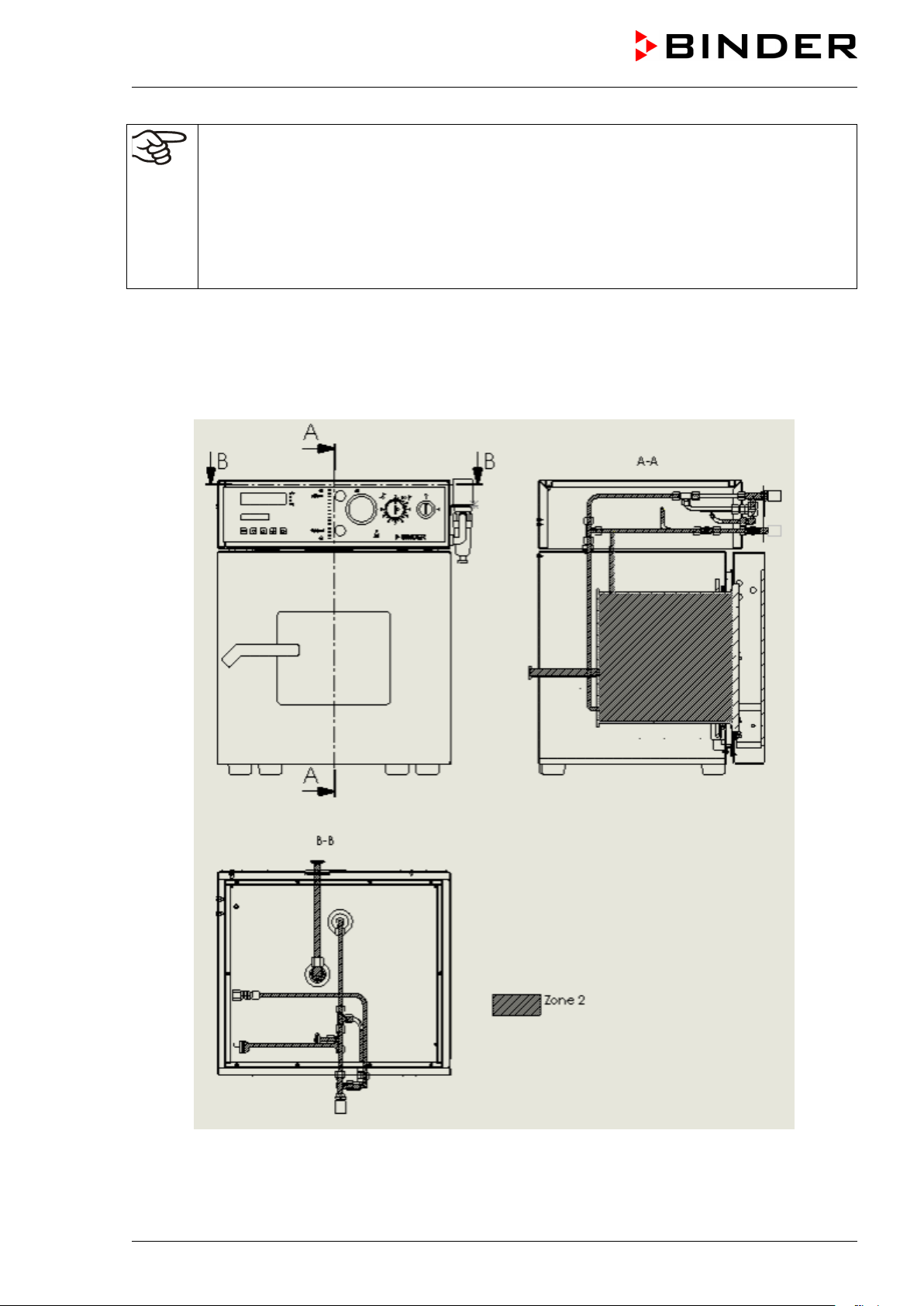
2.6 Overview of the zone classification of the ovens
VDL (E2.1) 04/2014 page 29/107
Figure 10: Zone classification VDL 23
Page 30

Figure 11: Zone classification VDL 53 and 115
VDL (E2.1) 04/2014 page 30/107
Page 31

3. Completeness of delivery, transportation, storage, and installation
3.1 Unpacking, and checking equipment and completeness of delivery
After unpacking, please check the unit and its optional accessories, if any, based on the delivery note for
completeness and for transportation damage. Inform the carrier immediately if transportation damage has
occurred.
The final tests of the manufacturer may have caused traces of the racks on the inner surfaces. This has
no impact on the function and performance of the unit.
Please remove any transportation protection devices and adhesives in/on the unit and on the doors and
take out the operating manuals and accessory equipment.
CAUTION
Sliding or tilting of the unit.
Damage to the unit.
Risk of injury by lifting heavy loads.
∅ Do NOT lift or transport the unit using the door, the handle, or the lower housing.
Lift units size 23 and 53 from the pallet at the four lower corners with the aid of 4 peo-
ple.
Lift units size 115 from the pallet with the aid of 6 people.
If you need to return the unit, please use the original packing and observe the guidelines for safe lifting
and transportation (chap. 3.2).
For disposal of the transport packing, see chap. 17.1.
If you ordered the option “vacuum module with chemical membrane pump”, the pump will be delivered in a
separate box and must be fitted into the module and connected at the place of installation (see chap.
15.3).
Note on second-hand units (Ex-Demo-Units):
Second-hand units are units that have been used for a short time for tests or exhibitions. They are thoroughly tested before resale. BINDER ensures that the chamber is technically sound and will work flawlessly.
Second-hand units are marked with a sticker on the unit door. Please remove the sticker before commissioning the unit.
VDL (E2.1) 04/2014 page 31/107
Page 32

3.2 Guidelines for safe lifting and transportation
After operation, please observe the guidelines for temporarily decommissioning the unit (chap. 17.2).
CAUTION
Sliding or tilting of the unit.
Damage to the unit.
Risk of injury by lifting heavy loads.
Transport the unit in its original packaging only.
For moving or shipping, secure the oven with transport straps.
∅ Do NOT lift or transport the unit using the door, the handle, or the lower housing.
Lift units size 23 and 53 at the four lower corners with the aid of 4 people.
Lift units size 115 with the aid of 6 people.
• Permissible ambient temperature range during transport: -10 °C / 14°F to +60 °C / 140°F.
You can order transport packing for moving or shipping purposes from BINDER Service.
3.3 Storage
Intermediate storage of the unit is possible in a closed and dry room. Observe the guidelines for temporary decommissioning (chap. 17.2).
• Permissible ambient temperature range during storage: -10 °C / 14°F to +60 °C / 140°F.
• Permissible ambient humidity: max. 70 % r.H., non-condensing
When after storage in a cold location you transfer the unit to its warmer installation site, condensation may
form. Before start-up, wait at least one hour until the chamber has attained ambient temperature and is
completely dry.
3.4 Location of installation and ambient conditions
Set up the VDL vacuum drying oven on a flat, even and non-flammable surface, free from vibration, in a
well-ventilated, dry location and align it using a spirit level. The site of installation must be capable of supporting the unit’s weight (see technical data, chap. 19.2). The chambers are designed for setting up inside
a building (indoor use).
CAUTION
Danger of overheating.
Damage to the unit.
∅ Do NOT set up units in non-ventilated recesses.
Ensure sufficient ventilation for dispersal of the heat.
• Permissible ambient temperature range during operation: +18 °C / 64°F to +32 °C / 90°F.
The ambient temperature should not be substantially higher than the indicated ambient temperature of +25 °C / 77°F to which the specified technical data relate. Deviations from the indicated data are possible for other ambient conditions.
• Permissible ambient humidity: 70 % r.H. max., non-condensing.
• Installation height: max. 2000 m / 6562 ft above sea level.
VDL (E2.1) 04/2014 page 32/107
Page 33

When placing several units of the same size side by side, maintain a minimum distance of 250 mm / 9.8 in
between each unit. Wall distances: rear 100 mm / 3.9 in, sides 135 mm / 5.3 in. Spacing above and behind the unit of at least 100 mm / 3.9 in must also be maintained.
CAUTION
Danger by stacking.
Damage to the units.
∅ Do NOT place vacuum drying ovens on top of each other.
To completely separate the unit from the power supply, you must disconnect the power plug. Install the
unit in a way that the power plug is easily accessible and can be easily pulled in case of danger.
Do not install or operate the vacuum drying oven VDL in potentially explosive areas.
DANGER
Explosion hazard.
Danger of death.
∅ Do NOT operate the unit in potentially explosive areas.
KEEP explosive dust or air-solvent mixtures AWAY from the vicinity of the unit.
If no pumps are used for pumping from zone 0 or zone 1, we recommend an explosion-preventing decoupling (explosion barrier, flame arrester, flame flash-through barrier acc. to EN 12874) between the inner
chamber and the vacuum pump. For installing a flame arrester, please contact the BINDER INDIVIDUAL
team.
Follow country-specific regulations for explosion protection.
Before commissioning the unit, connect the vacuum drying oven to the compressed air supply.
Without the necessary compressed air connection, the unit will not have a current to operate.
If you ordered the option “vacuum module with chemical membrane pump”, the pump will be delivered in a
separate box and must be fitted into the module and connected at the place of installation (chap. 15.3).
During operation a fire extinguisher must be available.
The maximum permissible ambient temperature of the vacuum pumps delivered by BINDER is 40 °C /
104°F.
Notes when using inert gas:
When operating the VDL safety vacuum drying oven with inert gas, correctly follow the technical ventilation measures, as described in the guideline BGI/GUV-I 850-0 on safe working in laboratories (formerly
BGR/GUV-R 120 or ZH 1/119 laboratory guidelines issued by the employers’ liability insurance association) (for Germany).
During operation with inert gas, the unit is supplied with an oxygen displacing gas (e.g. N
high concentrations are hazardous to health. They are colorless and almost odorless and therefore practically imperceptible. Inhalation of inert gases can cause drowsiness up to respiratory arrest. When the O
content of the air decreases below 18%, there is risk of death from lack of oxygen. Any gas that might
escape has to be led out via good room ventilation or a suitable exhaust system.
VDL (E2.1) 04/2014 page 33/107
). Inert gases in
2
2
Page 34

e inert gas supply: Close
WARNING
High concentration of inert gas.
Risk of death by suffocation.
∅ Do NOT set up units in non-ventilated recesses.
Ensure technical ventilation measures.
Respect the relevant regulations for handling these gases.
When decommissioning the vacuum drying oven, shut off th
valve (6).
4. Installation and connections
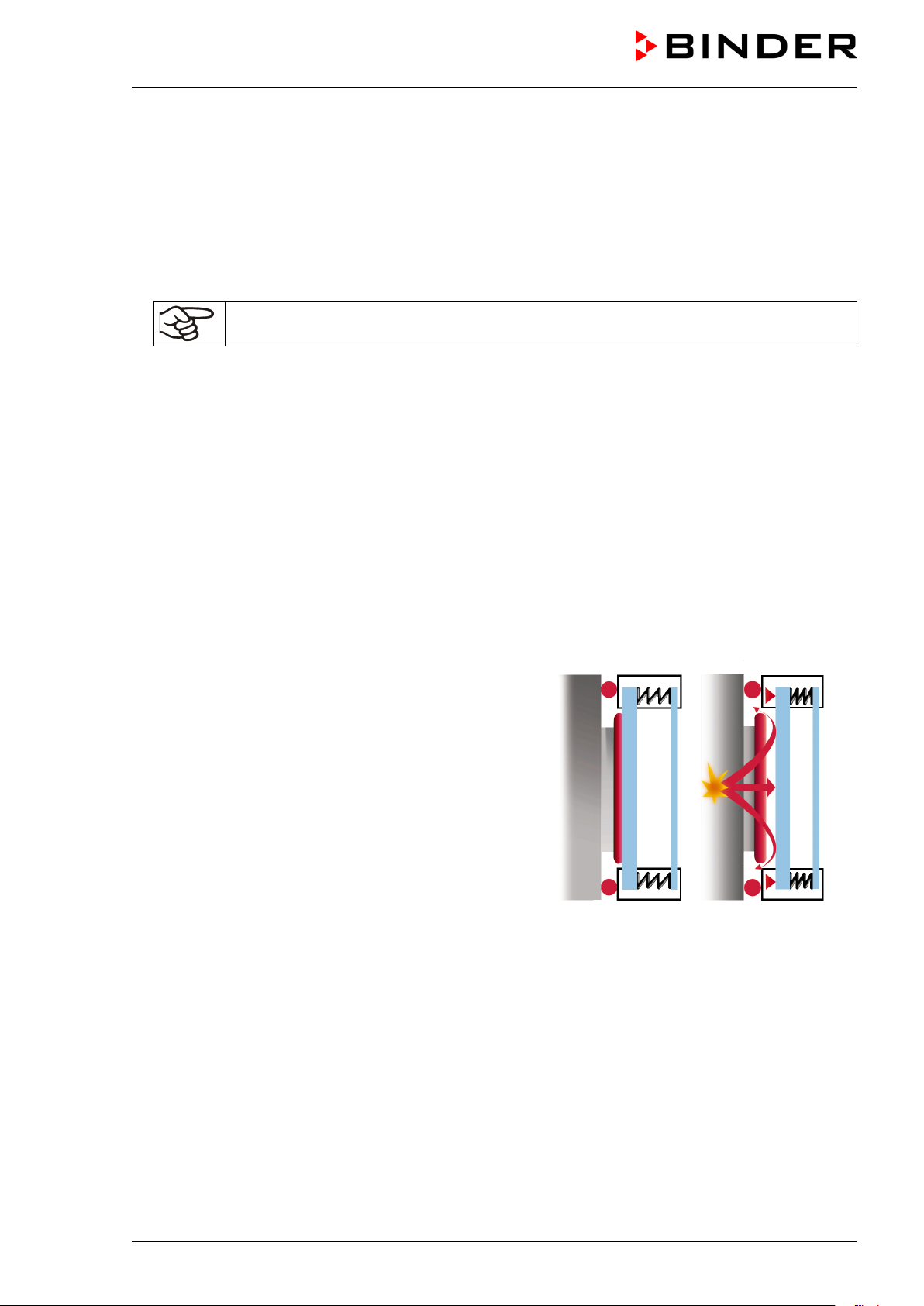
4.1 Vacuum expansion racks
The low-loss heat transfer to the material occurs via the patented aluminum vacuum expansion racks (also available in
stainless steel as an option). The strong tension causes the
racks to fit tightly against the interior wall and their largesurface contact area ensures rapid and effective heat transfer.
The removable rack holders allow for easy positioning.
You can also remove the expansion racks for easy cleaning.
Do not remove them too often in order to prevent wear.
Figure 12: Using the expansion racks
• Pushing the locking lever: The expansion rack is released and can be removed.
• Pulling the locking lever: The expansion rack is pressed against the inner chamber walls.
Following each new tightening of an expansion rack, check that the lateral parts of the rack fit
closely over their whole surface to the inner chamber wall. This is necessary in order to ensure
the specified temperature exactitude.
CAUTION
Invalid calibration.
∅ Do NOT change between aluminum and stainless steel racks
Use the delivered expansion racks only
VDL (E2.1) 04/2014 page 34/107
Page 35

4.2 Vacuum connection
Always connect the VDL vacuum drying oven to a vacuum pump or to a domestic vacuum system. For
this purpose, the vacuum connection (13) with small flange DN16 must be connected to the back of the
unit at the top with the vacuum pump or domestic vacuum system via a vacuum suction hose. For connecting to the unit, BINDER recommends the connection kits VP4 (Art. no. 8012-0621) or VP5 (Art. no.
8012-0622), (chap. 15.1).
With the option “stainless steel tubing” between the vacuum oven and vacuum module, the vacuum connection is already located inside the vacuum module.
Vacuum pumps with a suction capacity of 1-30 m³/h are suitable for the VDL vacuum drying
oven. Permissible end vacuum: 10
For use of vacuum pumps in the European Union, note the following points:
• Pertaining to units that will be operated in potentially explosive areas, the requirements of ATEX Di-
rective 94/9/EC have to be met as of July 1, 2003.
• If combustible solvent will be introduced into the inner chamber, the vacuum pump must be construct-
ed in a suitable explosion-proof manner. The mixtures extracted from the drying chamber must be carried away making sure that there is no danger by ignition of these atmospheres. Otherwise use flame
arresters.
Follow the safety instructions of the pump manufacturer.
In case of an explosion, the flame may be suctioned into the in-house vacuum system and result in further
explosions.
-2
mbar / 0.0003 inHg.
DANGER
Danger due to flame flash-through with in-house vacuum system.
Danger of death.
We recommend installing a flame arrester (flame flash-through barrier) according to EN
12874 between the vacuum drying oven and the in-house vacuum system.
For installing a flame arrester, please contact the BINDER INDIVIDUAL team.
In the event of an error, sparking in the pump motor or the switching elements, electrostatic discharges,
as well as hot pump parts can ignite solvent vapors. Minimize this risk by using an ATEX (Directive
94/9/EC) compliant vacuum pump suitable for suction from Zone 0 or 1 and, if appropriate, from the zone
of its installation site.
VDL (E2.1) 04/2014 page 35/107
Page 36

DANGER
Ignition of emerging solvent vapors due to sparking in the pump motor or the
switching elements, electrostatic discharges, hot pump parts.
Explosion hazard.
Danger of death.
Use only suitable, explosion-proof pumps
Operate the pump in a stationary position and secure it so it is immobile.
Install a fixed and conductive suction line to the vacuum connection (13).
Install a fixed and conductive exhaust pipe in case it may conduct ignitable solvent con-
centrations. This should be avoided by sufficient solvent condensation e.g., in an exhaust waste vapor condenser
When using ATEX (Directive 94/9/EC) non-compliant pumps: Provide a current-
dependent, delayed protective device for the pump (for the triggering time of this protective device, see the manufacturer’s specifications). The protective and monitoring device must not be able to independently turn on again or be released.
When using ATEX (Directive 94/9/EC) non-compliant pumps: Install the switch gear box
outside the hazardous area or provide it with explosion protection.
Assure that there is equipotential bonding between the pump housing and the housing
of the VDL vacuum drying oven via the connected equipment grounding conductors of
both units.
The ATEX (Directive 94/9/EC) compliant pumps offered by BINDER provide an integral protective device.
The ATEX (Directive 94/9/EC) compliant pumps offered by BINDER provide an integral explosion proof switch.
Make sure that the vacuum source is designed for a gas inlet temperature corresponding to
the used drying temperature, or take appropriate measures to cool down the extracted vapor
before it enters into the vacuum source.
The ATEX (Directive 94/9/EC) compliant vacuum pumps offered by BINDER are designed for a gas
inlet temperature of 40 °C / 104°F max. Do NOT exceed this temperature. If the gas inlet temperature is
too high and then becomes even warmer by compression in the pump, the resulting temperature (of the
gas-solvent mixture inside the pump) could exceed the solvent’s temperature class and ignition temperature.
DANGER
Exceeding the gas inlet temperature.
Exceeding the ignition temperature of the solvent.
Risk of ignition and explosion.
Damage to the vacuum pump.
Danger of death.
∅ Do NOT exceed a set-point temperature of 40 °C / 104°F.
With set-point temperature > 40 °C / 104°F take appropriate measures to cool down the
extracted vapor before it enters into the vacuum pump.
VDL (E2.1) 04/2014 page 36/107
Page 37

, shut off the inert gas supply: Close
4.2.1 Notes regarding use of vacuum pumps of other manufacturers
Connection to a vacuum source
Connect the vacuum connection (13) (small flange DN 16) at the back of the unit at the top to a vacuum
pump or domestic vacuum system via a vacuum conduit or fixed vacuum tubing.
Units that will be operated in potentially explosive areas, have to meet the requirements of
ATEX Directive 94/9/EC since July 1, 2003. Follow the safety instructions in chap. 1.5.
CAUTION
Excessive low pressure.
Risk of technical defects.
∅ The end vacuum must NOT fall below the permissible level of 10
Install a pump according to the permissible end vacuum or limit it via a vacuum control-
ler.
Extracted vapors can have a health damaging and/or corrosive effect on the unit and pump.
-2
mbar / 0.0003 inHg.
CAUTION
Release of extracted vapors.
Damage to health.
Corrosion of oven and pump.
Conduct the extracted vapors e.g., into a fume extractor facility. Connect a suitable
hose to the vacuum pump outlet (that may be located in the vacuum module).
4.3 Inert gas connection
When operating the VDL vacuum drying oven with inert gas, correctly follow the technical ventilation
measures, as described in the guideline BGI/GUV-I 850-0 on safe working in laboratories (formerly
BGR/GUV-R 120 or ZH 1/119 laboratory guidelines issued by the employers’ liability insurance association) (for Germany).
During operation with inert gas, the unit is supplied with an oxygen displacing gas (e.g. N
high concentrations are hazardous to health. They are colorless and almost odorless and therefore practically imperceptible. Inhalation of inert gases can cause drowsiness up to respiratory arrest. When the O
content of the air decreases below 18%, there is risk of death from lack of oxygen. Any gas that might
escape has to be led out via good room ventilation or a suitable exhaust system.
). Inert gases in
2
2
WARNING
High concentration of inert gas.
Risk of death by suffocation.
∅ Do NOT set up units in non-ventilated recesses.
Ensure technical ventilation measures.
Respect the relevant regulations for handling these gases.
When decommissioning the vacuum drying oven
valve (6).
VDL (E2.1) 04/2014 page 37/107
Page 38

Connection: Before commissioning, the existing compressed
independent of the oven’s operating state. Therefore the
Connect the inert gas supply to the inert gas connection (adapter with hose olive diameter 8 mm / 0.31 in)
via a pressure reducer. Screw the enclosed adapter with hose olive on the thread (11) at the unit rear. Set
the pressure reducer to a pressure slightly above ambient pressure. Make sure that the pressure reducer
will open. Do not alter this setting in order to avoid perturbation inside the oven and the release of large
quantities of inert gas after flooding the VDL.
CAUTION
Overpressure in the inner chamber.
Turbulence of the charging material.
∅ Do NOT modify the atmospheric pressure setting.
4.4 Compressed air / inert gas connection for sweeping the area for electrical equipment
The compressed air flows through the area for electrical equipment as well the preheating chamber, which
prevents a possible concentration of a solvent-containing atmosphere in the area for electrical equipment.
You can alternatively connect inert gas or nitrogen to the compressed air connection. Use only dry gas.
In order to avoid that any oil coming from the compressed-air piping enters the vacuum drying oven, the
compressor of the compressed air system must be equipped with an oil separator, or the compressed air
system must be constructed oil-free. The condensate separator of the compressed air connection separates water and soil from the compressed-air piping, thus leading to compressed air quality class 4 acc. to
ISO 8573-1. However, it does not prevent oil penetrating from the compressed air system, e.g. the compressed air compressor, into the compressed-air piping. The condensate separator is equipped with a
manual condensate outlet (chap. 16.1).
air unit must be connected on the right side of the unit (hose
olive ∅ 8 mm) to a compressed air line (compressed air system)
or to an inert gas supply. There must be an overpressure of at
least 1.5 bar / 44.3 inHg in the supply network. The maximally
permitted pressure is 7 bar / 206.7 inHg.
Immediately after connecting the compressed air or inert gas
supply, the area for electrical equipment of the oven will be
swept at 5 liters per minute. This air or inert gas quantity is used
and then released into the surrounding atmosphere permanently;
compressed air or inert gas connection on the building side
should be equipped with a stop valve that can be used to cut off
the gas supply, after having operated the drying oven.
If solvent-containing air penetrates the electrical area of the unit, explosions may result.
Figure 13: Compressed air connec-
tion with condensate separator
Solvent-containing air penetrating the electrical area of the unit.
VDL (E2.1) 04/2014 page 38/107
Explosion hazard.
∅ Do NOT take the air for the compressed air supply from explosive atmospheres.
If the unit is not connected to the compressed air supply, or if the specified overpressure is not
reached, it is impossible to start the VDL vacuum drying oven.
DANGER
Page 39

upply: Close
The compressed air connection is preset at the factory. Do NOT change the setting. In delivery
condition of the oven, this setting is protected by a cover with seal.
If the seal is broken, please inform BINDER Service to have the setting checked and to reinstall the cover with seal.
Notes when using inert gas:
When operating the VDL vacuum drying oven with inert gas, correctly follow the technical ventilation
measures, as described in the guideline BGI/GUV-I 850-0 on safe working in laboratories (formerly
BGR/GUV-R 120 or ZH 1/119 laboratory guidelines issued by the employers’ liability insurance association) (for Germany).
During sweeping the area for electrical equipment with inert gas, the unit is supplied with an oxygen displacing gas (e.g. N
almost odorless and therefore practically imperceptible. Inhalation of inert gases can cause drowsiness up
to respiratory arrest. When the O
of oxygen. Any gas that might escape has to be led out via good room ventilation or a suitable exhaust
system.
). Inert gases in high concentrations are hazardous to health. They are colorless and
2
content of the air decreases below 18%, there is risk of death from lack
2
WARNING
High concentration of inert gas.
Risk of death by suffocation.
∅ Do NOT set up units in non-ventilated recesses.
Ensure technical ventilation measures.
Respect the relevant regulations for handling these gases.
When decommissioning the vacuum drying oven, shut off the inert gas s
valve (6).
4.5 Electrical connection
• The VDL vacuum drying oven comes with a fixed power connection cable that has a length of 1800
mm / 5.9 ft. and a shockproof plug. The socket must also provide a protective conductor.
• Unit fuse 10 Amp
• Power supply voltage 230 V (1N~) ± 10 %, 50/60 Hz
• Prior to connection and start-up, check the power supply voltage. Compare the values to the specified
data located on the unit’s type plate (left side of the unit, bottom right-hand, chap. 1.4).
• When connecting, please observe the regulations specified by the local electricity supply company as
well as the VDE directives (for Germany)
• Pollution degree (acc. to IEC 61010-1): 2
• Over-voltage category (acc. to IEC 61010-1): II
CAUTION
Danger of incorrect power supply voltage.
Damage to the equipment.
Check the power supply voltage before connection and start-up.
Compare the power supply voltage with the data indicated on the type plate.
See also electrical data (chap. 19.2).
To completely separate the unit from the power supply, you must disconnect the power plug.
Install the unit in a way that the power plug is easily accessible and can be easily pulled in case
of danger.
VDL (E2.1) 04/2014 page 39/107
Page 40

Channel 1 Off,
Channel 1: Off,
Channel 1: On,
Channel 1 On,
5. Start up
DANGER
Solvent-containing air penetrating and concentration in the electrical area of the
unit.
Explosion hazard.
Before turning on the unit via the key switch (1), sweep the area for electrical equipment
at least 15 minutes with compressed air or inert gas. Sweeping the area for electrical
equipment must take place during the entire operation, as otherwise the VDL vacuum
drying oven will shut off at all poles.
After connecting the supply lines (chap 4) and checking all safety instructions and conditions of installation
and safe operation, turn on the unit via the key switch (1):
• Position 0: Oven is not operating
No consumption of compressed air or inert gas in the area for electrical equipment. If the fine dosage
valve (6) is open, inert gas may be used and can reach the ambient air.
• Position I: Oven is operating
If no indication appears in the display of the program controller RD3, the compressed air supply is probably not properly connected.
Warming chambers may release odors in the first few days after commissioning. This is not a quality defect. To reduce odors quickly we recommend heating up the chamber to its nominal temperature for one
day and in a well-ventilated location.
5.1 Settings at the RD3 program controller
After turning the unit on with the key switch (1) the controller is in Normal Display / Fixed value operation
mode.
Depending on the temperature value entered before, LED (7a) is lit if the heating is active, or no LED is lit
if the actual temperature is equal to or above the set-point.
In Display 1 of the controller the actual temperature value is displayed.
• With inactive week program timer:
In Display 2 of the controller the actual date and time are displayed. Example:
15.05.06 13:52
• With active week program timer:
In Display 2 of the controller the actual date and time and the states of the week program timer channels are displayed. Examples:
15.05.06 13:52 - - 15.05.06 13:52 - �
Channel 2: Off
VDL (E2.1) 04/2014 page 40/107
Channel 2: On
15.05.06 13:52 � -
Channel 2: Off
15.05.06 13:52 � �
Channel 2: On
Page 41

(7a) LED Heating active
Display 1
Display 2
(7b) (no function)
(7c) (no function)
(7d)
LED lit: program operation
LED flashing: exceeding of the
tolerance limits in “Fixed value
entry mode” or in “Program operation”. In program operation:
program interruption.
Figure 14: RD3 program controller
The program controller RD3 permits programming temperature cycles.
You can enter two programs with up to 10 sections each or one program with up to 20 sections (setting in
the user level, chap. 10).
When changing from 2 programs to 1 program or vice-versa, existing programs are deleted.
The maximum length of an individual program section can be set to either 99 h 59 min or to 999 h 59 min
(setting in the user level, chap. 10). This setting is then valid for all program sections.
Programming can be done directly through the keypad of the controller or graphically through the software
APT-COM™ 3 DataControlSystem (option, chap. 15.6) specially developed by BINDER.
5.2 General indications
The program controller RD3 offers several functional levels:
Normal Display / Fixed value operation:
• Display of the temperature actual value (display 1) and of the actual date and time (display 2).
• The oven is in fixed value operating mode, equilibrating to the entered set-points.
Fixed value entry mode (chap. 6)
• Entry of the temperature set-point for fixed value operating mode
• Entry of temperature set-points 1 and 2 for week program operation
Program editor (chap. 8)
• You can enter two programs with up to 10 sections each or one program with up to 20 sections (selec-
• Deleting a program section (chap. 8.4)
Program start level (chap. 9)
• Selection of an entered program
• Entry of settings affecting the program course, as “start delay time” or “number of program cycles”
• Program start
VDL (E2.1) 04/2014 page 41/107
tion in the user level, chap. 10). Entry of temperature set-points in all program sections (chap. 8.1).
Page 42

5 seconds
5 seconds
Menu visible only if week program
timer is activated in the user level
5 seconds
Week program editor (chap.7)
• Setting the shift points
User level (chap. 10)
• User specific controller settings
• Setting the real time clock
Normal Display / Fixed value operation
Fixed value entry mode Program editor Program start level
Week program editor
User level
If no button is touched within more than 120 sec., the controller returns from the current level to Normal
Display.
To avoid condensation inside the chamber and in the suction system, select an appropriate vacuum
source to ensure its sufficient performance in relation to the released amount of steam. Coordinate drying
temperature, suction performance of the vacuum source and the amount of charging material.
VDL (E2.1) 04/2014 page 42/107
Page 43

Display 1 shows
e.g. 39.8 C
(actual temperature value)
Display 2 shows
e.g. 15.05.06 13:52 - -
(actual date and time)
in the user level, chap. 10)
Display 1 shows
e.g. 40.0 C
(actual temperature set-point 1)
Display 2 shows
SP1 TEMPERATURE
(variable: temperature in °C)
Display 1 shows
e.g. 50.0 C
(actual temperature set-point 2)
in the user level, chap. 10)
Display 2 shows
SP2 TEMPERATURE
(variable: temperature in °C)
6. Fixed value entry mode
Solvents and resulting vapors can ignite at excessive drying temperatures.
DANGER
Excess drying temperature.
Ignition and explosion hazard.
Determine the maximum drying temperature in relation to the ignition temperature of the
solvent according to the information panel “Temperature setting” (chap. 2.5). Do NOT
exceed this temperature when presetting the set point on the RD3 temperature controller.
In case of solvent mixtures, use the ignition temperature of the material with the lowest
ignition temperature.
Before starting the drying process, set the temperature safety device (chap. 12) to the
maximum permitted drying temperature according to the information panel “Temperature setting” (chap. 2.5).
Start the drying process. The heating is only released when a vacuum of
125 ± 25 mbar / 3.69 ± 0.74 inHg) or below is reached.
If you do not want to use the week program timer, deactivate it (factory setting, setting in the
user level, chap. 10) before entering any set-points.
Basic entry principle: Access the individual parameters with button X/W. Enter the value with the arrow
keys. A value flashing once after 2 seconds indicates that it has been applied by the controller.
Normal Display
(actual switching state of week program timer channel 1: Off,
channel 2: Off, visible only if week program timer is activated
Press key
Enter temperature set-point in °C using
arrow keys
Press key
Value is shown in display 1.
Enter temperature set-point in °C using ar-
If no button is pressed within more than 120 sec, or if the “EXIT” button is pressed, the controller changes
to Normal Display.
VDL (E2.1) 04/2014 page 43/107
(visible only if week program timer is activated
Value is shown in display 1.
row keys
Press key
Page 44

When changing the set-point, check the setting of the safety device (chap. 12).
The values entered in fixed-value entry mode remain valid after program run-off and are then
equilibrated.
If the week program timer is active, depending on the running week program another set-point (SP2) may
be targeted. Resulting high temperatures may exceed the maximum permissible drying temperature of a
solvent in the drying material. Therefore, deactivate the week program timer if you do not use it (default
setting, setting in the User level, chap. 10).
DANGER
Exceeding the ignition temperature of a solvent after the program ends.
Risk of fire and explosion.
Danger of death.
Deactivate the week program timer if you do not use it.
VDL (E2.1) 04/2014 page 44/107
Page 45

Display 1 shows
e.g. 39.8 C
(actual temperature value)
Display 2 shows
(actual date and time, actual state of week program timer
channel 1: Off, channel 2: Off)
Display 1 shows
e.g. 0000
Display 2 shows
PROGRAM EDITOR
(you are in the “program editor”)
Display 1 shows
0000
Menu visible only if week program timer is activated
in the user level (chap. 10)
Display 2 shows
WEEK PROG. EDITOR
(you are in the “week program editor”)
Display 1 shows
0000
Display 2 shows
UserCod?
0000
(enter the user code, display flashes)
Display 1 shows
0000
Display 2 shows
(selection of day of the week)
(actual selection: Monday)
elect the day of the week (Monday up to
7. Week program editor
The Week program editor allows defining up to 4 shift point for each week day. A shift point defines a
moment and the switching state ON or OFF of the channels that become active in this instance.
Channel function:
• Channel 1 On = Set-point SP2 is equilibrated.
• Channel 1 Off = Set-point SP1 is equilibrated
• Channel 2 = reserve
The week program timer is initially set to inactive (factory setting). Therefore, you need to activate the week program timer in the user level (chap. 10).
Normal Display
e.g. 15.05.06 13:52 - -
Press down key
Press down key
Press program key
Enter the user code using arrow keys
Monday
S
Sunday) with key
for 5 sec
for 5 sec
Automatically forward after 2 sec
e.g. 0001 (basic setting, adjustable in the
user level, chap. 10).
Value is shown in both displays.
Day of the week is shown in display 2.
Press program key
VDL (E2.1) 04/2014 page 45/107
Page 46

Display 1 shows
0000
Display 2 shows
Shiftpt.
(no function)
Display 1 shows
0000
Display 2 shows
(selection of the shift point)
(actual shift point: 1)
Display 1 shows
e.g. --.--
(time of the selected shift point)
Display 2 shows
(actual selection of the shift point: S1)
(actual setting: shift point not programmed)
Display 1 shows
--.--
(time of the selected shift point)
Display 2 shows
(entry of the time of the selected shift point)
(actual setting: shift point not programmed)
Display 1 shows
0000
Display 2 shows
(entry of the state of channel 1)
(actual setting: Off)
Display 1 shows
0000
(actual setting: Off)
Display 1 shows
e.g., 08.30
(time of the selected shift point)
(actual setting: time 08.30, channels Off)
Press program key
Shiftpt. 1
Select the shift point (1 up to 4) with key
Press program key
S1: --:--
Press program key
Time --:--
Enter the time (hh:mm) using arrow keys
Press key
Ch1 = SP2: Off
Value is shown in display 2.
Value is shown in display 2.
Enter the state of channel 1
(On or Off) using arrow keys
Setting is shown in display 2.
Press key
Display 2 shows
Channel 2: Off
Enter the state of channel 2
(entry of the state of channel 2) (no function)
Setting is shown in display 2.
(On or Off) using arrow keys
Press key
Press key EXIT
Display 2 shows S1: 08:30 - - (actual selection of the shift point: S1)
Press program key
Press key EXIT twice
Select the next shift point Select the next day of the week
To exit the menu, Press several times key EXIT or wait for 120 seconds. Controller returns to normal display.
VDL (E2.1) 04/2014 page 46/107
Page 47

Day of the week
(temperature)
hh:mm
AM
PM
ON = SP2
OFF = SP1
ON
OFF
7.1 Program table template for the Week Program Editor
Program editor
Program title
Project
Date:
Time Channel 1
Monday S1
S2
S3
S4
Channel 2*
Tuesday S1
S2
S3
S4
Wednesday S1
S2
S3
S4
Thursday S1
S2
S3
S4
Friday S1
S2
S3
S4
Saturday S1
S2
S3
S4
Sunday S1
S2
S3
S4
• Channel 2 is non-functional in the standard unit
VDL (E2.1) 04/2014 page 47/107
Page 48

7.2 Programming example of the Week program editor
7.2.1 Desired time function
During the day (12 hours) the oven shall maintain a temperature of +80 °C / 176°F, and during the night
(12 hours) it shall cool down / stop heating (set-point 30 °C / 86°F).
This program shall automatically run during the whole year, i.e. it shall be programmed just once.
7.2.2 Proceeding overview
1. Settings in the User level (see chap. 10)
• Activating the week program timer
• Checking and, if necessary, setting the real time clock
2. Enter the set-points for the week program in “Fixed value entry mode” (see chap. 6)
Set-points for the example program:
SP1 (night / weekend) = 30 °C (Channel 1 ON = Controller adjusts to set-point SP2)
SP2 (day / week) = 80 °C (Channel 1 OFF = Controller adjusts to set-point SP1)
3. Enter the time program to the program editor
Program table for the example program:
Day of the week
hh:mm AM PM ON = SP2 (day)
Monday S1 06:00 ON
S2 18:00 OFF
Tuesday S1 06:00 ON
S2 18:00 OFF
Wednesday S1 06:00 ON
S2 18:00 OFF
Thursday S1 06:00 ON
S2 18:00 OFF
Time Channel 1 (temperature)
OFF = SP1 (night)
Friday S1 06:00 ON
S2 18:00 OFF
Saturday S1 06:00 ON
S2 18:00 OFF
Sunday S1 06:00 ON
S2 18:00 OFF
Make sure that no other shift points have been pre programmed. If so, they must be deleted:
Set the time of the respective shift point to “ --:-- ” using key .
VDL (E2.1) 04/2014 page 48/107
Page 49

Display 1 shows
e.g. 39.8 C
(actual temperature value)
gram timer channel 1: Off, channel 2: Off)
Display 1 shows
e.g. 0000
Display 2 shows
PROGRAM EDITOR
(you are in the “program editor”)
Display 1 shows
0000
Menu visible only if week program timer is activated.
Display 2 shows
WEEK PROG. EDITOR
(you are in the “week program editor”)
Display 1 shows
0000
Display 2 shows
USER – LEVEL
(you are in the user level)
Display 1 shows
0000
Display 2 shows
UserCod?
0000
(enter the user code, display flashes)
Display 1 shows 1 (actual address)
(entry of unit address)
(actual address: 1)
Display 1 shows
0000
(Week program timer active or inactive?
(actual setting: Active)
Display 1 shows
0000
(Display mode 12 hours or 24 hours?
(actual setting: 24h)
Display 1 shows
0000
Display 2 shows
Date (Main menu: Setting the date of the real time clock)
7.2.3 Proceeding in detail
1. Settings in the user level
• Activating the week program timer
• Checking and, if necessary, setting the real time clock
Normal Display
Display 2 shows
Enter the user code using arrow keys
e.g. 15.05.06 13:52 - -
Press down key
Press down key
Press down key
Press program key
(actual date and time, actual switching state of week pro-
for 5 sec
for 5 sec
for 5 sec
e.g. 0001 (basic setting, or the valid code in
case it has been previously changed in this
menu).
Value is shown in both displays.
Automatically forward after 2 sec
Display 2 shows Adress 1
Press several times key
Display 2 shows Prog.Clk Active
Select “Active” using arrow keys
Press key
Display 2 shows 12h/24h 24h
Press key
Press program key
until Prog.Clk appears:
Setting is shown in display 2.
VDL (E2.1) 04/2014 page 49/107
Page 50

Display 1 shows
e.g. 2006
(Actual setting: 2006)
Display 2 shows
Year
2006
(Setting the year of the real time clock)
Display 1 shows
e.g. 5
(Actual setting: may)
Display 2 shows
Month 5 (Setting the month of the real time clock)
Display 1 shows
e.g. 15
(Actual setting: 15)
Display 2 shows
Day
15
(Setting the day of the real time clock)
Display 1 shows
0000
Display 2 shows
Time (Main menu: Setting the time of the real time clock)
Display 1 shows
e.g. 13
(Actual setting: 13, i.e. 1 p.m.)
Display 2 shows
Hour
13
(Setting the hour of the real time clock)
Display 1 shows
e.g. 30
(Actual setting: 30 minutes)
Display 2 shows
Minute
30
(Setting the minute of the real time clock)
Display 1 shows
e.g. 39.8 C
(actual temperature value)
Display 2 shows
(actual date and time, actual switching state of week pro-
gram timer channel 1: Off, channel 2: Off)
Display 1 shows
30.0 C
(actual temperature set-point 1)
Display 2 shows
SP1 TEMPERATURE
(variable: temperature in °C)
Set year (2006 up to 2050) using arrow keys
Press key
Set month (1 up to 12) using arrow keys
Press key
Set day (1 up to 31) using arrow keys
Press key
Press key
Press program key
EXIT
Setting is shown in display 2.
Setting is shown in display 2.
Setting is shown in display 2.
Set hour (0 up to 23) using arrow keys
Setting is shown in display 2.
Press key
Set minute(0 up to 59) using arrow keys
Press several times key
EXIT
Setting is shown in display 2.
or wait for 120 seconds
Controller returns to normal display.
2. Enter the set-points for the week program in Fixed value entry mode (see chap.
Set-points for the example program:
SP1 (night / weekend) = 30 °C (Channel 1 ON = Controller adjusts to set-point SP2)
SP2 (day / week) = 80 °C (Channel 1 OFF = Controller adjusts to set-point SP1)
Normal Display
e.g. 15.05.06 13:52 - -
Press key
6)
Enter temperature set-point 30 °C
using arrow keys
VDL (E2.1) 04/2014 page 50/107
Value is shown in display 1.
Page 51

Display 1 shows
80.0 C
(actual temperature set-point 2)
Display 2 shows
SP2 TEMPERATURE
(variable: temperature in °C)
Display 1 shows
e.g. 39.8 C
(actual temperature value)
Display 2 shows
(actual date and time, actual state of week program timer
channel 1: Off, channel 2: Off)
Display 1 shows
e.g. 0000
Display 2 shows
PROGRAM EDITOR
(you are in the program editor)
Display 1 shows
0000
Display 2 shows
WEEK PROG. EDITOR
(you are in the week program editor)
Display 1 shows
0000
Display 2 shows
UserCod?
0000
(enter user code, display flashes)
Display 1 shows
0000
Display 2 shows
(selection of day of the week)
(actual selection: Monday)
Display 1 shows
0000
Display 2 shows
Shiftpt.
(no function)
Display 1 shows
0000
Display 2 shows
(selection of the shift point)
(actual shift point: 1)
Display 1 shows
e.g. --.--
(time of the selected shift point)
Display 2 shows
(actual selection of the shift point: S1)
(actual setting: shift point not programmed)
Press key
Enter temperature set-point 80 °C
using arrow keys
Press the EXIT button. The controller changes to Normal Display.
3. Enter the time program to the week program editor
Normal Display
e.g. 15.05.06 13:52 - -
Press down key
Press down key
Press program key
Enter the user code using arrow keys
Value is shown in display 1.
for 5 sec
for 5 sec
e.g. 0001 (basic setting, adjustable in the
user level, chap. 10).
Value is shown in both displays.
Automatically forward after 2 sec
Monday
Select the first day of the week (Monday)
with key
Press program key
Press program key
Shiftpt. 1
Select shift point 1 with key
Press program key
S1: --:--
Day of the week is shown in display 2.
Value is shown in display 2.
Press program key
VDL (E2.1) 04/2014 page 51/107
Page 52

Display 1 shows
06.00
(time of the selected shift point)
(entry of time of the selected shift point)
(actual setting: 6.00, i.e. 6 a.m.)
Display 1 shows
0000
(entry of state of channel 1)
(actual setting: On)
Display 1 shows
06.00
(time of the selected shift point)
(actual selection of the shift point: S1)
(actual setting: time 06.00, channel 1 ON)
Display 1 shows
0000
Display 2 shows
Shiftpt.
(no function)
Display 1 shows
0000
(actual shift point: 2)
Display 1 shows
e.g. --.--
(time of the selected shift point)
(actual selection of the shift point: S2)
(actual setting: shift point not programmed)
Display 1 shows
18.00
(time of the selected shift point)
(entry of time of the selected shift point)
(actual setting: 18.00, i.e. 6 p.m.)
Display 1 shows
0000
(entry of state of channel 1)
(actual setting: Off)
Display 1 shows
18.00
(time of the selected shift point)
(actual selection of the shift point: S2)
(actual setting: time 18.00, channel 1 OFF)
Display 2 shows Time 06:00
Enter the time 06:00 using arrow keys
Press key
Display 2 shows Ch1 = SP2: On
Enter the state of channel 1
On using arrow keys
Display 2 shows S1: 06:00 � -
Press program key
Press program key
Display 2 shows Shiftpt. 2
Press key EXIT
Value is shown in display 2.
Setting is shown in display 2.
to select the next shift point
(selection of the shift point)
Select shift point 2 with key
Press program key
Display 2 shows S2: --:--
Press program key
Display 2 shows Time 18:00
Enter the time 18:00 using arrow keys
Press key
Display 2 shows Ch1 = SP2: Off
Enter the state of channel 1
Off using arrow keys
Press key EXIT
Value is shown in display 2.
Value is shown in display 2.
Setting is shown in display 2.
Display 2 shows S2: 18:00 - -
Press key EXIT twice
to select the next day of the week
VDL (E2.1) 04/2014 page 52/107
Page 53

Display 1 shows
0000
Display 2 shows
(selection of day of the week)
(actual selection: Tuesday)
Display 1 shows
0000
Display 2 shows
Shiftpt.
(no function)
Display 1 shows
0000
(actual shift point: 1)
Display 1 shows
e.g. --.--
(time of the selected shift point)
Display 2 shows
(actual selection of the shift point: S1)
(actual setting: shift point not programmed)
Display 1 shows
06.00
(time of the selected shift point)
Display 2 shows
(entry of time of the selected shift point)
(actual setting: 6.00, i.e. 6 a.m.)
Display 1 shows
0000
(actual setting: ON)
Display 1 shows
06.00
(time of the selected shift point)
Display 2 shows
(actual selection of the shift point: S1)
(actual setting: time 06.00, channel 1 ON)
Tuesday
Select the next day of the week (Tuesday)
with key
Press program key
Press program key
Display 2 shows
Shiftpt. 1
Select shift point 1 with key
Press program key
S1: --:--
Press program key
Time 06:00
Day of the week is shown in display 2.
(selection of the shift point)
Value is shown in display 2.
Enter the time 06:00 using arrow keys
Display 2 shows
Ch1 = SP2: On
Enter the state of channel 1
On using arrow keys
S1: 06:00 � -
Press program key
Following entry of the complete program:
Press several times key EXIT
Value is shown in display 2.
Press key
(entry of state of channel 1)
Setting is shown in display 2.
Press key EXIT
to select the next shift point
etc.
or wait for 120 seconds
Controller returns to normal display.
VDL (E2.1) 04/2014 page 53/107
Page 54

8. Program editor
8.1 Selecting between set-point ramp and set-point step
You can program various kinds of temperature transitions. In the user level (chap. 10) you can select between the settings “Ramp” (default setting) and “Step”.
Setting “Ramp” allows programming all kinds of temperature transitions.
With setting “Step” the controller will equilibrate only to constant temperatures; programming
ramps is no longer possible.
Switching between settings “Ramp” and “Step” will influence all programs. Please note that this
can cause the time courses of existing programs to change significantly.
8.1.1 Programming with setting “Ramp” (default setting)
Set-points always refer to the start of a program section, i.e., at the beginning of each program section,
the entered set-point is reached. During program section operation, the temperature gradually passes to
the set-point entered for the subsequent program section.
You can program all kinds of temperature transitions by the appropriate design of the program section
timing:
• Gradual temperature changes “set-point ramp“
The set-point gradually moves from one set-point to the one of the following program section during a
given interval. The actual temperature value (X) follows the continually moving set-point (W) at any
time.
Temperature ramps can be programmed in order to extend the heating up times. This may be necessary in order to avoid temperature stresses in the material during the heating up phase. Heating up
times can be considerably slowed down by the use of temperature ramps.
• Program sections with constant temperature
The initial values of two subsequent program sections are identical; therefore the temperature remains
constant during the whole time of the first program section.
• Sudden temperature changes “set-point step”
Steps are temperature changes (ramps) that occur during a very short interval. Two program sections
with an identical set-point are followed by a section with a different set-point. If the duration of this transitional program section is very short (minimum entry 1 min), the temperature change will proceed rapidly in the minimum amount of time.
VDL (E2.1) 04/2014 page 54/107
Page 55

01
02 03
04
05
06
07
08
09
W
t
W/°C
t/min.
S01
S02
S03
S04
0
20
40
60
80
100
30
120
180
380
S05
SEC
TIME
S01
40
00:30
S02
60
01:30
S03
90
01:00
S04
90
03:20
S05
20
00:01
Figure 15: Possible temperature transitions
(with default setting “ramp” in the user level (chap. 10)
A heating up rate of 1.5 °C/min can be regarded as the realistic maximum.
If the oven is charged to full capacity, depending on the load, deviations from the specified
heating up times may occur.
Program entry as set-point ramp (example):
Program table corresponding to the diagram (with default setting “Ramp”):
Section
Temperature
set-point
[ °C]
TEMP
Section length
[hh.mm]
You can now enter the values of such a program table to the RD3 program controller (chap. 8.2).
VDL (E2.1) 04/2014 page 55/107
Page 56

W/°C
t/min.
S01 S02 S03 S04 S05 S06 S07 S08
0
20
40
60
80
100
30
120
180
380
Section
SEC
Temperature
Section length
TIME
S01
40
00:30
S02
40
00:01
S03
60
01:30
S04
60
00:01
S05
80
01:00
S06
80
00:01
S07
20
03:20
S08
20
00:01
Program entry as set-point step (example):
Program table corresponding to the diagram (with default setting “Ramp”):
set-point
[ °C]
[hh.mm]
TEMP
You can now enter the values of such a program table to the RD3 program controller (chap. 8.2).
Program the end point of the desired cycle with an additional section (in our examples S05 for set-point
ramp and S08 for set-point step) with a section time of at least one minute. Otherwise, the program will
stop one section too early because the program line is incomplete.
VDL (E2.1) 04/2014 page 56/107
Page 57

W/°C
t/min.
S01 S03 S05 S07
0
20
40
60
80
100
30
120
180 380
Section
SEC
Temperature
Section length
TIME
S01
40
00:30
S02
60
01:30
S03
80
01:00
S04
20
03:20
8.1.2 Programming with setting “step”
With setting “Step” selected, you don’t need to program the transition section in the Program Editor.
With setting “step” the controller will equilibrate only to constant temperatures; programming
ramps is no longer possible.
The set-points are maintained constant for the duration of a program section. At the start of each program
section, the unit heats up with the maximum speed in order to attain the entered set-point
Program entry as set-point step (example):
Program table corresponding to the diagram (with setting “Step”):
set-point
[ °C]
[hh.mm]
TEMP
You can now enter the values of such a program table to the RD3 program controller (chap. 8.2).
VDL (E2.1) 04/2014 page 57/107
Page 58

Section
SEC
Temperature set-point
TEMP
Section length
TIME
S01
40
00:30
S02
60
01:30
S03
90
01:00
S04
90
03:20
S05
20
00:01
8.1.3 General notes on programming temperature transitions
When exceeding the tolerance limits set in the user level (chap. 10), the program is interrupted until the
actual temperature value returns to within the tolerance range. During this program interruption, the LED
(7d) flashes. Therefore, the duration of the program may be extended due to the programming of tolerances
The programming is saved even in case of a power failure or after turning off the unit.
Solvents and the resulting vapors can ignite at excessive drying temperatures.
DANGER
Excess drying temperature.
Ignition and explosion hazard.
Determine the maximum drying temperature in relation to the ignition temperature of the
solvent according to the information panel “Temperature setting” (chap. 2.5). Do NOT
exceed this temperature when presetting the set point on the RD3 temperature controller.
In the case of solvent mixtures, use the ignition temperature of the material with the
lowest ignition temperature.
Before starting the drying process, set the temperature safety device (chap. 12) to the
permitted maximum drying temperature according to the information panel “Temperature setting” (chap. 2.5).
The heating is only released when a vacuum of 125 ± 25 mbar / 3.69 ± 0.74 inHg) or
below is reached. Only then should you start the program.
After program rundown the controller returns to fixed value operation showing Normal Display and equilibrates to the temperature value previously entered in fixed value entry mode.
Before starting the program, check the set-point value entered in fixed value entry mode. After
program rundown temperature will equilibrate to this value.
Deactivate the week program timer (factory setting, setting in the user level, chap. 10) before
starting a program.
8.2 Set-point entry for program operation
From Normal Display, press down button X/W for 5 sec to access the program editor. Then enter the setpoints one after the other in all program sections of a selected program.
You can enter two programs with up to 10 sections each or one program with up to 20 sections (setting in
the user level, chap. 10).
In order to avoid incorrect programming, we recommend entering the values of the program course into a
table (template in chap. 8.3).
Example of program table (with default setting “Ramp”):
VDL (E2.1) 04/2014 page 58/107
[ °C]
[hh.mm]
Page 59

Display 1 shows
e.g. 39.8 C
(actual temperature value)
(actual date and time, actual switching state of week pro-
gram timer channel 1: Off, channel 2: Off)
Display 1 shows
e.g. 0000
Display 2 shows
PROGRAM EDITOR
(you are in the program editor)
Display 1 shows
0000
Display 2 shows
UserCod? 0000
(enter user code)
Display 1 shows
e.g. 01
(program P01 selected)
Display 2 shows
alternating
--- : --- PRG.
(program can be selected)
CONTINUE X/W
(information: to 1st program section with X/W)
Display 1 shows
e.g. 01
(section S01 selected)
Section S01 has already been created.
X/W
Display 1 shows
e.g. 01
(section S01 selected)
Section S01 has not yet been created.
You can now enter the values of the program table to one of the program places of the RD3 program controller.
Step 1 – Selecting the program and the first program section to be entered:
Normal Display
Display 2 shows e.g. 15.05.06 13:52 - -
Press down key
Press program key
Enter user code using arrow keys
Automatically forward after 2 sec.
Select program P01 or P02 using arrow keys
Press key
for 5 sec.
e.g. 0001
(basic setting, adjustable in the user level,
chap. 10).
Value is shown in both displays.
Value is shown in display 1.
In the selected program P01 or P02, program sections can be selected:
Display 2 shows
alternating
P01: --- SEC.
Enter new set-points for the individual variables with button
CONTINUE X/W
or:
Display 2 shows
alternating
Select sections S01 to S10 or to S20 using
P01: --- SEC.
NEW SEC. X/W
arrow keys
Enter set-points for the individual variables with button X/W
As long as no program section has been entered, the display switches back to 01 in case of any entry
> 01, because all sections need to be entered one after the other, and each new section is created as
NEWSEC.
Example: If three program sections have been already entered, the next section to be entered is S04.
Before this, no section > S04 can be selected.
VDL (E2.1) 04/2014 page 59/107
Page 60

Display 1 shows
e.g. 40.0C
(actual temperature set-point)
alternating
S01: TEMP 40.0
(variable: temperature in °C)
CONTINUE X/W
(information: go on with X/W)
Display 1 shows
e.g. 00.30
(actual section length set-point)
S01: TIME 00:30
(variable: section length in hh:mm)
CONTINUE X/W
(information: go on with X/W)
Display 1 shows
e.g. 02
(section S02 selected)
Display 2 shows
P01: --- SEC.
Section S02 has already been created.
CONTINUE X/W
Display 1 shows
e.g. 02
(section S02 selected)
Display 2 shows
Section S02 has not yet been created.
NEW SEC. X/W
Display 1 shows
e.g. 60.0C
(actual temperature set-point)
Display 2 shows
alternating
S02:TEMP 60.0
(variable: temperature in °C)
CONTINUE X/W
(information: go on with X/W)
Next step –set-point entry in the desired program sections:
Basic entry principle: Access the parameters of individual program sections with button X/W one after
the other. Enter the values of the individual parameters with the arrow keys. A value flashing once after 2
seconds indicates that it has been adopted by the controller. If several parameters are to be skipped (e.g.
in order to change a parameter in a posterior program section), the parameters can be rapidly jumped
over by holding down the X/W key. If no button is pressed for more than 120 sec the controller switches
back to Normal Display. The program entered to this point remains stored.
Display 2 shows
Enter temperature set-point of S01 in °C
using arrow keys
Display 2 shows
alternating
Enter section length set-point of S01 in
hh.mm using arrow keys
Selecting the next program sections to be entered
alternating
Press key
Press key
Press key
Value is shown in both displays.
Enter new set-points for the individual parameters with X/W.
or:
P01: --- SEC.
alternating
Select the next section to be entered using
arrow keys
Enter the temperature set-point of S02 in °C
using arrow keys
Enter set-points for the individual parameters with X/W
Etc.
If all sections up to S10 or up to S20 have been programmed, section S01 follows again. In order to quit
the entry mode, press the “EXIT” button several times or wait 120 sec. → the controller will then return to
Normal Display.
When changing the set-point, check the setting of the safety device (chap. 12).
VDL (E2.1) 04/2014 page 60/107
Page 61

Program editor
Program title
Project
Program No.
Date:
Section
Temperature set-point
Section length
8.3 Program table template
SEC
S01
S02
S03
S04
S05
S06
S07
S08
S09
S10
S11
S12
S13
S14
[ °C]
TEMP
[hh.mm]
TIME
S15
S16
S17
S18
S19
S20
VDL (E2.1) 04/2014 page 61/107
Page 62

Display 1 shows
e.g. 0000
Display 2 shows
PROGRAM EDITOR
(you are in the program editor)
Display 1 shows
0000
Display 2 shows
UserCod? 0000
(enter user code)
Display 1 shows
e.g. 01
(program P01 selected)
Display 2 shows
alternating
--- : --- PRG.
(program can be selected)
CONTINUE X/W
(information: to 1st program section with X/W)
Display 1 shows
e.g. 01
(actual selection of the section: S01)
P01: --- SEC.
(program section can be selected)
CONTINUE X/W
(information: set-point entry with X/W)
Display 1 shows
e.g. 90.0C
(actual temperature set-point)
Display 2 shows
S03:TEMP 90.0
(variable: temperature)
CONTINUE X/W
(information: continue with X/W)
Display 1 shows
e.g. 01.00
(actual section length)
Display 2 shows
S03:TIME 01:00
(variable: section length)
CONTINUE X/W
(information: continue with X/W)
Display 1 shows
e.g. 00.00
(actual section length)
Display 2 shows
S03:TIME 00:00
(variable: section length)
DELETE SEC. X/W
(information: delete section with X/W)
8.4 Deleting a program section
A program section is deleted from the program by setting the section duration to Zero.
Normal display
Press down key
Press program key
Enter the user code using arrow keys
Automatically forward after 2 sec
Select the desired program, e.g. P01, using
arrow keys
Press key
In the selected program P01 or P02, program sections can be selected:
for 5 sec.
e.g. 0001 (basic setting, adjustable in the user
level, chap. 10).
Value is shown in both displays.
Value is shown in display1.
Display 2 shows
alternating
Select desired section, e.g. S03, using arrow
keys
Press key
alternating
Press key
alternating
Enter set-point Zero for section length in
hh:mm of S03 using arrow keys
alternating
Press key
No entry
(omitted if section S01 shall be deleted).
Value is shown in display 2 or in both displays
(display depends on maximum time setting in
the user level chap. 10)
VDL (E2.1) 04/2014 page 62/107
Page 63

Display 1 shows
e.g. 03
(actual selection of the section: S03)
Display 2 shows
alternating
P01:S03
(program section can be selected)
CONTINUE X/W
(information: set-point entry with X/W)
The following section (in our example now S03) is displayed:
Press key
Controller returns to Normal Display
If you delete a program section which is followed by further sections, those following move up
in place of the deleted section.
In our example, section S03 has been deleted. If sections S04, S05, etc. have been programmed earlier,
they will now replace the preceding sections, i.e., S04 is now called S03 etc.
Deletion leads to overwriting the section by the following one. It is therefore not possible to temporarily
inactivate a program section. To enter a section later to a program, all the sections following the new one
must be entered again.
“EXIT”
or wait 120 sec
9. Program start level
Before starting the program, check the set-point entered in Fixed value operation mode. After end of the
program, the temperature will equilibrate to this value. This value must NOT exceed the maximum permissible drying temperature of a solvent contained in the drying material.
DANGER
Exceeding the ignition temperature of a solvent after the program ends.
Risk of fire and explosion.
Danger of death.
∅ Set-point of Fixed value operation must NEVER reach the ignition temperature of a
contained solvent. For safety reasons, always ensure that there is a safety margin
(chap. 2.5).
Check the set-point of Fixed value operation and if necessary adapt it acc. to the tem-
perature setting information panel (chap. 2.5).
After the program ends, the temperature will equilibrate to the set-point entered in Fixed value operation
mode. If the week program timer is active, another set-point (SP2) may be targeted according to programming. Too high temperatures can occur which exceed the maximum permissible drying temperature
of a solvent contained in the drying material. Deactivate the week program timer before starting the program (default setting, setting in the User level, chap. 10).
DANGER
Exceeding the ignition temperature of a solvent after the program ends.
Risk of fire and explosion.
Danger of death.
Deactivate the week program timer before starting the program.
VDL (E2.1) 04/2014 page 63/107
Page 64

Display 1 shows
e.g. 1
(actual selection of the program)
Display 2 shows
SEL.PRG.
(select program 1 or 2)
Display 1 shows
e.g. 00.00
(entered delay time hh.mm)
Display 2 shows
RUN TIME
(enter delay time of program start)
Display 1 shows
e.g. -1
(actual selection of the number of program cycles)
Display 2 shows
REPEAT
(enter number of program cycles)
In the first step, select a program. This is on condition that a program has been entered previously (chap.
8.2) and that program type “2 programs with 10 sections each” has been selected in the user level (chap.
10).
Then define the settings for the program course. Two parameters can be set:
• Program delay time, i.e. a defined time before a program starts. It can be entered with a precision of 1
minute, and its maximum value is 99.59 (99 h 59 min). If the value is 00.00, the program will start immediately.
• Number of program cycles, i.e. the desired number of program repeats. Values from 1 to 99 can be
entered. If the program is not going to be repeated, enter the value “0”. For indefinite repeats enter the
value “–1”. The program is repeated as a whole; it is not possible to repeat individual sections.
In the last step start the selected program. These steps must be carried out subsequently.
Deactivate the week program timer (factory setting, setting in the user level, chap. 10) before
starting a program.
Step 1 – Program selection (only with program type “2 programs” set)
Normal Display
Press program key
Enter program number 1 or 2 with
arrow keys
Next step – entry of program course settings
Press program key
Set delay time in hh.mm using arrow keys
Press program key
Select number of cycles -1, 0, 1 etc. using
arrow keys
Value is shown in display 1.
Value is shown in display 1.
Value is shown in display 1.
VDL (E2.1) 04/2014 page 64/107
Page 65

Display 1 shows
e.g. 1
(selected program)
Display 2 shows
RUN PRG.
(Question: start selected program?)
Display 1 shows
e.g. 25.5 C
actual temperature value
Display 2 shows
P01:S01 00:29:39
(time running backwards)
(actual program P01, actual section S01, and remaining
time of program section S01)
Display 1 shows
e.g. 65.5 C
(actual temperature value)
Display 2 shows
(actual program P01, actual section S03, and remaining time
of program section S03)
Display 1 shows
e.g. 90 C
(actual temperature set-point 1)
Display 2 shows
SP1 TEMPERATURE
Display 1 shows
e.g. 30 C
(actual temperature set-point 2)
Display 2 shows
SP2 TEMPERATURE
(no function during program operation)
Last step – program start
Press program key
Press program key
Program is running. The green LED (7d) lights up.
In addition to the green LED (7d) indicating a running program, the LED (7a) is lit if the heating is active, or
not lit if the actual temperature equals the set-point.
During program course the arrow keys and the “EXIT” button are not functional.
By pressing program key for 3 seconds, you can terminate the program course.
If you press button during program course, the entered set-point of the actually running program section is shown for 5 sec:
P01:S03 00:47:12
Press key
5 seconds
5 seconds
After program rundown (and, if appropriate, of the program repeats) the controller returns to fixed value
operation showing Normal Display and equilibrates to the temperature value previously entered in fixed
value entry mode.
VDL (E2.1) 04/2014 page 65/107
Page 66

10. User level
In this menu you can set the following parameters (in brackets the corresponding abbreviated information
given in display 2):
• Unit address (Adress)
Setting of controller address (1 to 255) for operation with the communication software APT-COM™.
• User code (User-cod)
Modification of the user code setting (factory setting 0001) for access to the user level and the program
editor.
Keep in mind any modification of the user code. There is no access to these levels without a valid user code.
• Decimal point position (Decimal)
Selection if integer values or one position after the decimal point can be entered. The integer representation is shown in Display 2 (set-point entry) while the actual value in Display 1 is always shown with
one decimal point.
• Audio alert (Buzzer)
Inactive: no audible signal (buzzer) in case of an alarm event.
Active: in case of an alarm event (see chap. 11.2) an audible signal (buzzer) will sound. It can be reset
by pressing the “EXIT” button.
• Selection of controller menu language (Language)
German, English, or French can be selected.
• Counter of operating hours (Oper.hs)
Information about the number of operating hours currently reached or since the last reset (no setting,
display only).
• Max. number of operating hours (Op.limit)
Entry of a limit number of operating hours, i.e., the maximum number of operating hours that can be
run. Maximum setting: 9999. Reaching the limit has no effect.
• Reset operating hours (Op.back)
Reset operating hours to zero.
• Interface protocol (Protocol)
“Modbus”: The unit interface can be used as a communication interface to connect it to a computer.
This serves to control the unit by the communication software APT-COM™. It is possible to read and
write the values of all parameters.
“Printer”: A protocol printer for data printouts can be connected to the unit interface. At the printer the
actual temperature value is regularly protocolled with fixed formatting and with adjustable print intervals.
In both cases an interface converter RS 422 / RS 232 is used.
• Print interval (Prt.-Inv.)
Setting of the print interval in minutes. Function is available only if setting “Printer” has been selected in
the previous menu point.
• Display illumination (Disp.LED)
Selection between continuous display illumination and limited illumination that will automatically go off
300 sec. after the last entry.
VDL (E2.1) 04/2014 page 66/107
Page 67

• Program type selection (PrgSelec)
Select between entry of two programs with up to 10 sections each or of one program with up to 20 sections.
When changing from 2 programs to 1 program or vice-versa, existing programs are deleted in the program editor!
• Maximum section duration (Prg.Time)
The maximum length of an individual program section can be set to either 99 h 59 min or to 999 h 59
min. This setting is then valid for all program sections.
When changing the maximum duration setting, pre-existing programs will be deleted in
the program editor.
• Set-point programming type (Setp.sim)
Selection between “Ramp” and “Step”. With setting “Step” selected, you don’t need to program the
transition section in the Program Editor.
If you select setting “step”, the controller will equilibrate only to constant temperatures;
programming ramps becomes impossible.
A change between settings “ramp” and “step” will influence all programs. Note that significant change in time courses may arise in existing programs.
• Tolerance limit range (Tol.band)
Entry of a tolerance limit value in °C. If the actual value of temperature exceeds the set-point of a program section by more than the entered tolerance limit value, the program is halted (LED (7d) flashes)
until the actual temperature value is again within the tolerance range
Entry of “0” means tolerance limits are off.
• Activating or inactivating the week program timer (Prog.Clk)
“Inactive”: The week program timer is turned off (factory setting). The corresponding setting menu
(chap. 7) is not visible, nor is set-point 2 in the “Fixed value entry mode” (chap. 6).
“Active”: The week program timer is activated.
When deactivating the week program timer, any programming made in advance will remain in memory and take effect when the week program timer is activated again.
Deactivate the week program timer before staring a program (chap. 9).
• Display mode (12h/24h)
Select between 12 hours (display “AM” or “PM”) or 24 hours.
• Date of the real time clock (Date)
Main menu. Use the program key to access the settings of year, month, and day in the corresponding
submenus.
• Year of the real time clock (Year)
Enter the year (2006 up to 2050)
• Month of the real time clock (Month)
Enter the month (1 up to 12).
• Day of the real time clock (Day)
Enter the day (1 up to 31).
VDL (E2.1) 04/2014 page 67/107
Page 68

Display 1 shows
e.g. 39.8 C
(actual temperature value)
Display 2 shows
(actual date and time, actual switching state of week pro-
gram timer channel 1: Off, channel 2: Off)
Display 1 shows
e.g. 0000
Display 2 shows
PROGRAM EDITOR
(you are in the program editor)
Display 1 shows
0000
Menu visible only if week program timer is activated.
Display 2 shows
WEEK PROG. EDITOR
(you are in the week program editor)
Display 1 shows
0000
Display 2 shows
USER – LEVEL
(you are in the user level)
Display 1 shows
0000
Display 2 shows
UserCod?
0000
(enter user code, display flashes)
Display 1 shows 1 (actual address: 1)
Display 2 shows
(entry of unit address)
(actual address: 1)
Display 1 shows 1 (actually valid user code: 1)
Display 2 shows
(change user code)
(actually set: 1)
• Time of the real time clock (Time)
Main menu. Use the program key to access the settings of hour and minute in the corresponding sub-
menus.
There is no automatic switch between daylight saving time and regular time.
• Hour of the real time clock (Hour)
Enter the hour (0 up to 23).
• Minute of the real time clock (Minute)
Enter the minute (0 up to 59).
Normal Display
e.g. 15.05.06 13:52 - -
Press down key
Press down key
Press down key
Press program key
Enter the user code using arrow keys
Automatically forward after 2 sec
for 5 sec
for 5 sec
for 5 sec
e.g. 0001 (basic setting,
or the valid code in case it has been previously
changed in this menu).
Value is shown in both displays.
Adress 1
Enter the unit address (1 up to 254) using
arrow keys
User-cod 1
Enter a new value using arrow keys
VDL (E2.1) 04/2014 page 68/107
Press key
Address is shown in both displays.
Value is shown in both displays.
Page 69

Display 1 shows
0000
(no function)
Display 2 shows
Saf.mode: Limit
(no function)
Display 1 shows
0
(no function)
Display 2 shows
Saf.setp
0
(no function)
Display 1 shows
0000
(no function)
Display 2 shows
(setting of decimal point position)
(actual setting: XXX.X)
using arrow
Display 1 shows
0000
(no function)
Display 2 shows
(setting of the alarm buzzer)
(actual setting: „Active“)
using
Display 1 shows
0000
(no function)
Display 2 shows
(selection of controller language)
(actual setting: English)
lish,
Display 1 shows
e.g. 0004
(unit operating hours)
Display 2 shows
(operating hours up to now hhhh:mm)
(actually shown: 4 hs 28 min)
Display 1 shows
1000
(actual setting: 1000 hs)
Display 2 shows
1000:00 (maximum number of operating hours
hhhh:mm (actual setting: 1000 hs)
Display 1 shows
0000
(no function)
Display 2 shows
(reset counter of operating hours ?)
(actual setting: No)
using arrow
Press key
Press key
Press key
Decimal: XXX.X
Select decimal point position
Press key
Buzzer : Active
Select between “Active” and “Inactiv”
arrow keys
Press key
Language : English
keys
Decimal point position XXX.X or XXXX. is
shown in display 2.
Setting is shown in display 2.
Select between languages German, Eng
and French using arrow keys
Press key
Oper.hs 0004:28
Press key
Op.limit
Set value using arrow keys
Press key
Op.back : No
Select between “Yes” and “No”
keys
Setting is shown in display 2.
Setting is shown in both displays.
Setting is shown in display 2.
VDL (E2.1) 04/2014 page 69/107
Page 70

Display 1 shows
0000
(no function)
Display 2 shows
(Selection of interface mode)
(actual setting: Modbus)
Display 1 shows
e.g. 3
(actual setting: 3 min)
Display 2 shows
(print interval)
(actual setting: 3 min)
Display 1 shows
0000
Display 2 shows
(continuous display illumination?)
(actual setting: No)
Display 1 shows
0000
Display 2 shows
(1 program with max. 20 sections or
(actual setting: 2Prg10S)
using arrow keys
Display 1 shows
0000
Display 2 shows
(max. section length 99:59 or 999:59?)
(actual setting: 99:59)
hhh:mm using arrow keys
Display 1 shows
0000
Display 2 shows
(ramp or step?)
(actual setting: ramp)
Display 1 shows
0000
Display 2 shows
(Tolerance limits in °C)
(actual setting: 0)
Display 1 shows
0000
Display 2 shows
(Week program timer active or inactive?
(actual setting: Inactive)
Press key
Protocol: MODBUS
Select between protocols “MODBUS” and
“Printer” using arrow keys
Press key
Prt-Inv. 3
Select value between 0 and 255 minutes
using arrow keys
Press key
Disp.LED: No
Select between “Yes” and “No” using arrow
keys
Press key
PrgSelec: 2Prg10S
Select between “2Prg10S” and “1Prg20S”
Press key
Setting is shown in display 2.
Setting is shown in displays 1 and 2.
Setting is shown in display 2.
2 programs with max. 10 sections each?)
Setting is shown in display 2.
Prg.Time: 99:59
Select between 99:59 in hh:mm or 999:59 in
Press key
Setp.sim Ramp
Select between Ramp and Step using arrow
keys
Press key
Tol.band 0
Set value in °C using arrow keys
Press key
Prog.Clk Inactive
Setting is shown in display 2.
Setting is shown in display 2.
Setting is shown in display 2.
VDL (E2.1) 04/2014 page 70/107
Page 71

arrow keys
Display 1 shows
0000
(actual setting: 24h)
ing arrow keys
Display 1 shows
0000
Display 2 shows
Date (Main menu: Setting the date of the real time clock)
Display 1 shows
e.g. 2006
(Actual setting: 2006)
Display 2 shows
Year
2006
(Setting the year of the real time clock)
Display 1 shows
e.g. 5
(Actual setting: may)
Display 2 shows
Month 5 (Setting the month of the real time clock)
Display 1 shows
e.g. 15
(Actual setting: 15)
Display 2 shows
Day
15
(Setting the day of the real time clock)
Display 1 shows
0000
Display 2 shows
Time (Main menu: Setting the time of the real time clock)
Display 1 shows
e.g. 13
(Actual setting: 13, i.e. 1 p.m.)
Display 2 shows
Hour
13
(Setting the hour of the real time clock)
Display 1 shows
e.g. 30
(Actual setting: 30 minutes)
Display 2 shows
Minute
30
(Setting the minute of the real time clock)
Select between “Active” and “Inactive” using
Press key
Display 2 shows
12h/24h 24h
Select between 12 hours and 24 hours us-
Press key
Set year (2006 up to 2050) using arrow keys
Setting is shown in display 2.
(Display mode 12 hours or 24 hours?
Setting is shown in display 2.
Press program key
Press key
Setting is shown in display 2.
Set month (1 up to 12) using arrow keys
Press key
Set day (1 up to 31) using arrow keys
Press key
Press key
Press program key
Set hour (0 up to 23) using arrow keys
Press key
EXIT
Setting is shown in display 2.
Setting is shown in display 2.
Setting is shown in display 2.
Set minute(0 up to 59) using arrow keys
Press several times key
VDL (E2.1) 04/2014 page 71/107
Setting is shown in display 2.
EXIT
or wait for 120 seconds
Controller returns to normal display.
Page 72

(2)
(2a)
(2b)
11. Performance in case of failures
11.1 Performance after power failures
Power failure during fixed-value operation (Normal Display):
The entered parameters remain saved. After power returns, operation continues with the set parameters.
Power failure during program operation:
After the power returns, program course continues with the set-points that have been reached previously
during program operation.
11.2 Alarm messages
Alarm messages, e g. “RANGE ERROR CH1” in case of sensor rupture, are shown in Display 2 only in
Normal Display.
A buzzer can be activated / deactivated in the user level (chap. 10). It can be reset by pressing the “EXIT”
button. The alarm text shown in Normal Display goes off only if the cause of the alarm does not exist any
longer.
12. Safety device class 2 (DIN 12880)
The safety device protects the vacuum drying oven, its environment and the charging material from exceeding the maximum permissible temperature.
Please observe the guideline BGI/GUV-I 850-0 on safe working in laboratories (formerly BGR/GUV-R 120
or ZH 1/119 laboratory guidelines issued by the employers’ liability insurance association) and BGR 104
(formerly ZH 1/10 laboratory guidelines issued by the employers’ liability insurance association) (for Germany).
Set the safety-device to the maximally permitted drying temperature according to the information panel
“temperature setting” (chap. 2.5), to prevent exceeding the maximum drying temperature in case of a
default. In the event of a fault in the temperature controller, the safety device (2) permanently turns off
the vacuum drying oven. This status is reported visually by the indicator lamp (2a).
Check the operation of the safety device (2) by moving it slowly counter-clockwise until it is turned off. The
safety device cut-off is reported visually by the indicator lamp (2a).
Then release the safety device by pressing the reset button (2b), and turn on the VDL vacuum drying oven
as described previously.
Figure 16: Temperature safety device class 2
Function:
The safety device is functionally and electrically independent of the temperature control device and turns
off the unit at all poles.
If you turn the control knob (2) to its end-stop (position 10) the safety device will protect the appliance. If
you set it to a temperature a little above the set-point temperature, it will protect the charging material.
VDL (E2.1) 04/2014 page 72/107
Page 73

• Turn the control knob (2) of the safety device using a coin to its
If the safety device has turned off the oven, identifiable by the red alarm lamp (2a) lighting up, proceed as
follows:
• Disconnect the oven from the power supply
• Have an expert examine and rectify the cause of the fault
• Release the safety device by pressing the reset button (2b)
• Restart the oven as described in chap. 4.5.
Adjustment:
To check the response temperature of the safety device, turn on the chamber and set the desired set
point on the temperature controller.
The scale division from 1 to 10 corresponds to the temperature range from 30 °C / 86°F up to 320 °C /
608°F and serves as a setting aid.
end-stop (position 10) (unit protection).
• When the set point is reached, turn back the control knob (2) until
its trip point (turn it counter-clockwise) is reached.
• The red alarm lamp (2a) lighting up identifies the trip point; and the
reset button (2b) pops out.
• The optimum setting of the safety device is obtained by turning the
knob clockwise by approx. one graduation mark on the scale.
• Push the reset button (2b) in again.
The unit is only active when the reset button (2b) is pushed in.
When the safety device responds, the red alarm lamp (2a) illuminates, the reset button (2b) pops out, and
the oven is turned off permanently at all poles.
Check the setting regularly and adjust it following changes of the set-point or charge.
Example: A substance with an ignition temperature of 160 °C shall be dried.
The maximum allowed drying temperature is 85 °C according to the information panel
“Temperature setting” at the front of the unit (chap. 2.5). Set the temperature safety device
to a temperature of 85 °C max.
Also, the setting on the controller RD3 must not exceed this value.
According to IEC/CEI 60079-14 this unit is not designated for the temperature classes T4, T5, and T6.
Introduce only substances with an ignition temperature which is higher than 135 °C / 275°F.
Figure 17: Setting the safety
device class 2
This unit is not suitable to dry substances with an ignition temperature below 135 °C / 275°F.
Explosion hazard.
VDL (E2.1) 04/2014 page 73/107
Danger of death.
∅ Do NOT introduce any substance with an ignition temperature #135 °C / 275°F into the
oven.
DANGER
Page 74

13. Reference measurements. Checking the temperature in the inner chamber
The controller display was adjusted in the factory to the temperature in the center of the usable volume
(chap. 19.1). The sensor probe of the reference measuring device was connected firmly to an expansion
rack positioned in the middle of the unit.
Checking the controller display
• Conduct the reference sensor into the inner chamber through the measuring port (15). The port must
be largely vacuum tight to enable a typical operation vacuum for the calibration. For a high vacuum,
use a measuring access port (option). At low vacuum, a silicone plug with a hole for the sensor wire is
sufficient.
• Fix the sensor to the center of an expansion rack in the middle of the useable volume with adhesive
aluminum tape or thermal conductive paste to ensure sufficient thermal conductivity.
• Perform the measurement in a thermally stable condition with 3 expansion racks and empty oven.
• Equilibrating time: at least 12 hours.
Checking the spatial temperature exactitude
• Fix at least 9 sensor probes on 3 racks with adhesive aluminum tape or thermal conductive paste to
ensure sufficient thermal conductivity
• The distance of the sensor probes to all inner chamber walls must be at least 10% of the correspond-
ing inner chamber dimension (see DIN 12880).
• Perform the measurement in a thermally stable condition with 3 expansion racks and empty oven.
• Response time: at least 12 hours.
Do NOT use the temperature probe of the reference measurement device without any contact
to the expansion rack, i.e., do NOT measure vacuum values!
In case the temperature probe is a thermo element, mount it so it is electrically insulated from
the rack.
If you note an excessive divergence between the controller and reference temperatures, please contact
BINDER Service to calibrate the temperature controller.
14. Commissioning the vacuum
With regard to operation, please observe the guideline BGI/GUV-I 850-0 on safe working in laboratories
(formerly BGR/GUV-R 120 or ZH 1/119 laboratory guidelines issued by the employers’ liability insurance
association) (for Germany).
Starting situation: The vacuum source is connected and ready for operation.
For the vacuum module with chemical membrane pump option, see chap. 15.3.
VDL (E2.1) 04/2014 page 74/107
Page 75

• Turn on the vacuum pump.
37.5 mm Hg
14.1 Evacuation
• Close the aeration valve (5) and the fine dosing valve for inert gas (6).
• Turn the lever of the vacuum shut off valve (8) to
the “ON” position (valve open).
• Monitor the internal pressure on the pressure
display (3). The analog manometer displays the
running evaporation respectively the end of the
drying procedure. The scale of the manometer (3)
refers to an ideal ambient pressure of 1013 mbar /
29.9 inHg. Tolerance: 50 mbar /
(Torr) / 1.5 inHg (2.5% of the final scale value +
reading precision).
• When the desired end vacuum is obtained, turn
the VDL vacuum shutoff valve (8) to the “OFF”
position (valve closed). The reached vacuum is
now maintained.
The permissible end vacuum is 10-2 mbar / 0.0003 inHg.
14.2 Breaking the vacuum (flooding with ambient air)
When the drying procedure is complete, the vacuum in the inner container is broken (flooded).
• Open aeration valve (5) and fine dosing valve for inert gas (6)
• As soon as aeration valve (5) is open, fresh air is sucked in through the fresh air connection (12).
When the fine dosing valve for inert gas (6) is open, fresh air is sucked in through the inert gas connection (11).
Fresh air is introduced into the lower part of the rear panel of the inner chamber where it is evenly distributed in the inner chamber. This supply of fresh air by under-flooding prevents turbulence of pulverized
drying material.
14.3 Operation with inert gas
When operating the VDL vacuum drying oven with inert gas, correctly follow the technical ventilation
measures, as described in the guideline BGI/GUV-I 850-0 on safe working in laboratories (formerly
BGR/GUV-R 120 or ZH 1/119 laboratory guidelines issued by the employers’ liability insurance association) (for Germany).
Figure 18: Manometer display
During operation with inert gas, the unit is supplied with an oxygen displacing gas (e.g. N
). Inert gases in
2
high concentrations are hazardous to health. They are colorless and almost odorless and therefore practically imperceptible. Inhalation of inert gases can cause drowsiness up to respiratory arrest. When the O
content of the air decreases below 18%, there is risk of death from lack of oxygen. Any gas that might
2
escape has to be led out via good room ventilation or a suitable exhaust system.
VDL (E2.1) 04/2014 page 75/107
Page 76

WARNING
High concentration of inert gas.
Risk of death by suffocation.
∅ Do NOT set up units in non-ventilated recesses.
Ensure technical ventilation measures.
Respect the relevant regulations for handling these gases.
When decommissioning the vacuum drying oven, shut off the inert gas supply: Close
valve (6).
Install a pressure reducer for inert gas operation. Set the pressure reducer to a pressure slightly above
ambient pressure. Ensure that the pressure reducer will open. Do not change this setting in order to avoid
perturbation inside the oven and release of big quantities of inert gas after flooding the VDL.
Following evacuation, an inert gas, e.g., nitrogen, is led into the inner chamber via the fine dosing valve for
inert gas (6), until pressure compensation with the atmosphere occurs. Depending on the individual application, you can perform a second evacuation and repeat the inert gas flooding.
When the inert gas fine dosing valve is open, a maximum of approx. 0.6 m³/h gas flows into the inner
chamber. The introduction of inert gas by under-flooding in the lower region of the inner chamber rear wall
and the extraction at the inner chamber ceiling allow an effective inert gas flushing.
15. Options
15.1 ATEX connection kits for vacuum pumps VP4 or VP5 (option)
Connection kit for VP4 (Art. no. 8012-0621) consists of:
• Straining ring DN10/16 (3 pc.)
• Universal centering ring DN10/16 (3 pc.)
• Transition piece, adapter DN 16-10/8 (2 pc.)
• Vacuum hose 10/8, 2 m / 78.7 in
• Union nut M14 (2 pc.)
• Elbow DN 10/10
Connection kit for VP5 (Art. no. 8012-0622) consists of:
• Straining ring DN 10/16 (2 pc.)
• Straining ring DN 20/25
• Universal centering ring DN 10/16 (2 pc.)
• Outer centering ring DN 20/25
• Transition piece, adapter DN 16-10/8
• Transition piece, adapter DN 25-DN10/8 with union nut M14
• Union nut M14
• Vacuum hose 10/8, 2 m / 78.7 in
• Elbow DN 10/10
For mounting the VDL connection kits for VP4 or VP5, please refer to the mounting instructions Art. no. 7001-0152 supplied with each connection kit.
VDL (E2.1) 04/2014 page 76/107
Page 77

(13)
CAUTION
15.2 Vacuum module empty (without pump) (option)
The mounting instructions Art. no. 7001-0137 supplied with the vacuum module describe
how to mount the VDL vacuum drying oven onto the vacuum module and installing the
suction line to the vacuum module.
Connection to a vacuum source
Connect the vacuum connection (13) (small flange DN 16) at the
rear of the unit at the top to a vacuum pump or to a domestic
vacuum system via a vacuum hose or a fixed vacuum pipe.
When using a vacuum hose, we recommend using the BINDER
connection kits for VP4 or VP5 (chap. 15.1). The module has an
appropriate hose outlet at the back.
Figure 19: VDL 53 with the option “Vacuum module”, mounted,
and installed vacuum hose
Technical defects due to excessive negative pressure.
Danger of implosion.
Damage to the unit.
∅ The end vacuum must NOT fall below the permissible level of 10
Install the pump according to the permissible end vacuum or limit the end vacuum via a
vacuum controller.
Avoid the solvent accumulation in the vacuum module (option) as this would cause the vacuum
module to become an explosive area (Zone 0 or 1 or 2). The VDL vacuum drying oven located
on top of the module is not explosion-proof constructed in regards to its surroundings.
VDL (E2.1) 04/2014 page 77/107
-2
mbar / 0.0003 inHg.
Page 78

Inappropriate execution of the pump connection can lead to the risk of explosion.
DANGER
Inappropriate pump connection.
Risk of ignition and explosion.
Danger of death.
It is important to observe the pump manufacturer’s instructions regarding correct con-
nection and commissioning.
Observe the safety advice of chap. 1.5.
Extracted vapors or the occasionally used inert gas can endanger health and/or have a corrosive effect on
the oven and pump.
WARNING
Release of extracted vapors.
Danger of injury.
Damage to the oven and pump by corrosion.
Remove the extracted vapors and, if appropriate, the inert gas from the module via a
suitable conduit into e.g., a fume extractor facility.
Directly connect the conduit to the corresponding pump outlets.
Confirm that the vacuum source is designed for a gas inlet temperature corresponding to the
used drying temperature, or take appropriate measures to cool down the extracted vapor before its entry into the vacuum source.
A gas inlet temperature of 40 °C / 104°F maximum must NOT be exceeded. If the gas inlet temperature is too high and then becomes even warmer by compression in the pump, the resulting temperature
(of the gas-solvent mixture inside the pump) could exceed the solvent’s temperature class and ignition
temperature.
DANGER
Exceeding the gas inlet temperature.
Exceeding the ignition temperature of the solvent.
Risk of ignition and explosion.
Damage to the vacuum pump.
Danger of death.
∅ Do NOT exceed a set-point temperature of 40 °C / 104°F.
With set-point temperature > 40 °C / 104°F, take appropriate measures to cool down
the extracted vapor before its entry in the vacuum pump.
VDL (E2.1) 04/2014 page 78/107
Page 79

15.3 Vacuum module with chemical membrane pump VP4 or VP5 (option)
The mounting instructions Art. no. 7001-0137 supplied with the vacuum module describe
how to mount the VDL vacuum drying oven onto the vacuum module and installing the
suction line into the vacuum module.
The VP4 or VP5 chemical membrane pump is located in a separate transport packaging. Both pump
types are delivered as complete pump stations with a separator and an exhaust waste vapor condenser.
(13)
Figure 20: VDL 53 with option vacuum module with pump
(13) Vacuum connection
VDL (E2.1) 04/2014 page 79/107
Page 80

Cooling water outlet (hose nozzle 6 mm)
Guard plate
Cooling water outlet (hose nozzle 6 mm)
Outlet port (gas!)
Avoid the solvent accumulation in the vacuum module (option) as this would cause the vacuum
module to become an explosive area (Zone 0 or 1 or 2). The VDL vacuum drying oven located
on top of the module is not explosion-proof constructed in regards to its surroundings.
Outlet port (gas!)
Exhaust waste vapor
condenser
Cooling water inlet (hose
nozzle 6 mm / 0.23 in)
Round bottom flask as con-
densate catchpot
Figure 21: Vacuum pump VP4 (MZ2C EX)
Carrying handle
Inlet (vacuum connection)
Exhaust waste vapor
condenser
Cooling water inlet
(hose nozzle 6 mm /
0.23 in)
Collector bottle as
condensate catchpot
Inlet
(vacuum connection)
Round bottom flask
as condensate
catchpot
Figure 22: Vacuum pump VP5 (MZ4C EX)
VDL (E2.1) 04/2014 page 80/107
Page 81

Defining the zone of the installation site of the vacuum pump (guideline 1999/92/EC)
If the pump module is defined as Zone 1, the operating chamber of the vacuum pump must be swept with
inert gas. A flow of at least 1 liter per minute (without pressure) is needed. For Zone 2 or without any zone
sweeping with inert gas is not needed. In addition to sweeping with inert gas, in case of condensing media, you can connect a gas ballast in order to avoid condensation.
Installation of the supplied vacuum pump
• The vacuum drying oven is mounted onto the vacuum module as described in the mounting instruc-
tions Art. no. 7001-0137.
• The suction line is installed to the vacuum module as described in the mounting instructions Art. no.
7001-0137.
• When the pump is removed from the original packaging, place it in the vacuum module.
• Connect the pre-installed suction line to the vacuum pump inlet at the suction-side small flange con-
nection located at the top of the condensate flask.
• Connect a conduit that is suitable for removing the extracted vapors from the module, onto the pres-
sure-side connection of the vacuum pump (hose olive on the top-back of the emission condenser).
• Guide the end of the conduit into an exhaust air system, which is explosion-proof constructed in con-
sideration of any possible residual solvent contents. The operator must check if an explosive atmosphere may be present at the pump exit or at the exhaust waste vapor condenser. For this purpose, use
a calculation of the solvent’s partial pressure at the set-up coolant temperature of the exhaust waste
vapor condenser and compare it to the explosion limits of the pumped solvent. The exhaust solvent
concentration should be minimized by selecting the most appropriate condensation temperature for the
solvent at the refrigeration plant that can be connected to the exhaust waste vapor condenser. The
pumped-out gases at the pump exit or the exhaust waste vapor condenser must be removed in a controlled manner and according to applicable security regulations. If there is any possibility that an explosive mixture could still exist, the exhaust must be removed through antistatic conduits and disposed of
according to the valid regulations of explosion protection.
• The electrical connection is established at the pump’s connector box. This must be carried out accord-
ing to the original user manual of the pump manufacturer and to EN 60079-14. In addition, the zone
that has been defined by the user for the installation site of the pump must be correctly observed.
Equipotential bonding between the pump housing and the housing of the VDL vacuum drying oven
must be assured by the connected equipment grounding conductors of both units.
Inappropriate execution of the pump connection can lead to the risk of explosion.
DANGER
Inappropriate pump connection.
Risk of ignition and explosion.
Danger of death.
It is obligatory to follow the instructions of the pump manufacturer regarding correct
connection and commissioning.
Observe the safety advice as in chap. 1.5.
Extracted vapors or the occasionally used inert gas can endanger health. They can also have a corrosive
effect on the oven and pump.
VDL (E2.1) 04/2014 page 81/107
Page 82

WARNING
Release of extracted vapors.
Danger of injury.
Damage to oven and pump by corrosion.
Remove the extracted vapors and, if appropriate, the inert gas from the module via a
suitable conduit into e.g., a fume extractor facility.
Directly connect the conduit to the corresponding pump outlets.
You can connect a laboratory cooling system to the emission condenser of the vacuum pumps
VP4 or VP5.
To operate the chemical membrane pumps VP4 (MZ2C EX) or VP5 (MD4C EX), please
refer to the enclosed pump manufacturer's operating manual.
Confirm that the vacuum source is designed for a gas inlet temperature corresponding to the
used drying temperature, or take appropriate measures to cool down the extracted vapor before its entry into the vacuum source.
The ATEX (Directive 94/9/EG) compliant vacuum pumps offered by BINDER are designed for a gas
inlet temperature of 40 °C / 104°F max. Do NOT exceed this temperature. If the gas inlet temperature is
too high and then becomes even warmer by compression in the pump, the resulting temperature (of the
gas-solvent mixture inside the pump) could exceed the solvent’s temperature class and ignition temperature.
DANGER
Exceeding the gas inlet temperature.
Exceeding the ignition temperature of the solvent.
Risk of ignition and explosion.
Damage to the vacuum pump.
Danger of death.
∅ Do NOT exceed a set-point temperature of 40 °C / 104°F.
With set-point temperature > 40 °C / 104°F, take appropriate measures to cool down
the extracted vapor before its entry into the vacuum pump.
The maximum permissible ambient temperature of the vacuum pumps delivered by BINDER is 40 °C /
104°F.
15.4 Additional measuring channel for digital object temperature display with flexible Pt 100 temperature sensor (option)
The object temperature display permits recording the object temperature directly on or in the drying material. The object temperature is measured via a flexible Pt100 sensor inside the inner chamber. The sensor
needs to be in thermally conducting contact with the charging material. It can be plunged into humid
charging material up to the length of its protecting tube.
VDL (E2.1) 04/2014 page 82/107
Page 83

Display 1 shows
e.g. 24.6 C
(actual temperature value)
Display 2 shows
24.4 15:41
(actual object temperature in °C, actual time)
The object temperature is indicated on Display 2 of the RD3 controller.
Figure 23:
Standard Display without the
object temperature display option
Figure 24:
Display with the
object temperature display option
The object temperature data is put out combined with the temperature data of the controller to the RS 422
interface as a second measuring channel. This permits recording by the BINDER documentation software
APT-COM™ DataControlSystem (option, chap. 15.6).
Assembly and connection of the object temperature recording
• Insert the Pt 100 temperature sensor from the rear through the measuring connection (15) into the
inner chamber.
• The 3 contacts of the Pt 100 sensor are conducted outside via a measuring access port. From there,
establish the connection to the DIN socket (14) at the top of the rear panel of the unit marked “Pt100”.
For reasons of explosion protection, this electrical connection to the inner chamber is conducted via a
triple internal safety barrier with a conducting-state voltage of 1.6 Volt maximum against ground.
Figure 25: Figure 26: Figure 27:
Measuring connection (15)
with measuring access port
Plug for connection cable to
Measuring current port with universal
eccentric ring and locking ring DN 16, with
flexible Pt 100 temperature sensor
Pt100 connection (14) at
the rear of the unit
DIN socket “Pt 100”
Technical data of the Pt 100 sensor:
• Three-wire technique
• Class B (EN 60751)
• Temperature range up to 300 °C / 572°F
• Stainless steel protective tube, length 45 mm / 1.77 in, stainless steel material no. 1.4501
If the oven is charged to full capacity, depending on the load, deviations from the specified
heating up times may occur.
VDL (E2.1) 04/2014 page 83/107
Page 84

The measuring access port allows creating electrical connec-
Pin allocation of the RS 422 interface (9):
pin 2: RxD (+)
pin 7: GND
15.5 Measuring access port vacuum 9 poles (option)
tions for low voltages or sensors between the exterior and interior of the VDL vacuum drying oven. A 9 poles plug for the outside
is included.
Figure 28: Measuring connection (15)
with measuring access port and supplied plug
Connections at the measuring access port
• At the inner side of the measuring access port you can solder up to 9 cables. The inside connections
must be insulated against each other and against ground. Use 300 °C / 572°F solder.
• The 9 contacts are conducted outside via the measuring access port. You can use them to connect a
device via the supplied plug.
Maximum load capacity of the switching contacts: 42 V AC/DC - 2A
DANGER
Electrical hazard.
Danger of death.
Damage to switching contacts and connection socket.
∅ Do NOT exceed the maximum switching load of 42 AC/DC – 2 Amp.
∅ Do NOT connect any devices with a higher load capacity.
Insulate the inside connections against each other and against ground. Use 300 °C /
572°F solder.
15.6 Communication software APT-COM™ 3 DataControlSystem (option)
The unit is regularly equipped with a serial interface RS 422 (9) that can connect the BINDER communication software APT-COM™ 3 DataControlSystem. The actual temperature value is given at adjustable intervals. Programming can be performed graphically via PC. Up to 30 chambers with RS 422 interface can
be cross-linked. For further information, refer to the operating manual of the BINDER communication
software APT-COM™ 3.
Confirm that the interface mode is correctly set to “Modbus” in the user level (chap. 10).
VDL (E2.1) 04/2014 page 84/107
pin 3: TxD (+)
pin 4: RxD (-)
pin 5: TxD (-)
Page 85

16. Maintenance, cleaning, and service
16.1 Maintenance intervals, service
DANGER
Electrical hazard.
Danger of death.
∅ The unit must NOT become wet during operation or maintenance work.
∅ Do NOT remove the rear panel of the unit.
Before conducting maintenance work, turn off the unit at the main power switch and
disconnect the power plug.
Ensure all maintenance work is conducted by licensed electricians or experts authorized
by BINDER.
Ensure regular maintenance work is performed at least once a year.
The warranty becomes void if maintenance work is conducted by non-authorized personnel.
Replace the door gasket only when cold. Otherwise, the door gasket may become damaged.
We recommend taking out a maintenance agreement. Please consult BINDER Service:
BINDER telephone hotline: +49 (0) 7462 2005 555
BINDER fax hotline: +49 (0) 7462 2005 93555
BINDER e-mail hotline: service@binder-world.com
BINDER service hotline USA: +1 866 885 9794 or +1 631 224 4340 x3 (toll-free in the USA)
BINDER service hotline Asia Pacific: +852 390 705 04 or +852 390 705 03
BINDER service hotline Russia and CIS +7 495 988 15 16
BINDER Internet website http://www.binder-world.com
BINDER address BINDER GmbH, post office box 102, D-78502 Tuttlingen
International customers, please contact your local BINDER distributor.
The condensate separator is equipped with a manual condensate outlet. When condensate has accumulated in the condensate separator, you can let it off by opening the discharging screw at the bottom. With
connected supply pressure for sweeping the area for electrical equipment, condensate may spout.
CAUTION
Opening the discharging screw with connected supply pressure for sweeping the
area for electrical equipment.
Danger by spouting condensate.
Wear eye protectors when the supply pressure for sweeping the area for electrical
equipment is connected.
VDL (E2.1) 04/2014 page 85/107
Page 86

16.2 Cleaning and decontamination
Clean the unit after each use to avoid potential corrosion damage by ingredients of the charging material.
DANGER
Electrical hazard.
16.2.1 Cleaning
Disconnect the oven from the power supply before cleaning. Disconnect the power plug.
Danger of death.
∅ Do NOT spill water or cleaning agents over the inner and outer surfaces.
Before cleaning, turn off the unit at the main power switch and disconnect
the power plug.
Completely dry the appliance before turning it on again.
Wipe the surfaces with a moistened towel. In addition, you can use the following cleaning agents:
Exterior surfaces,
inner chamber,
door gaskets
Expansion racks,
rack holders
Instrument panel Standard commercial cleaning detergents free from acid or halides.
Filter of compressed air
supply
Zinc coated hinge parts
rear unit wall
Do not use cleaning agents that may cause a hazard due to reaction with components of the device or the
charging material. If there is doubt regarding the suitability of cleaning products, please contact BINDER
service.
We recommend using the neutral cleaning agent Art. No. Art. Nr. 1002-0016 for a thorough
cleaning.
Any corrosive damage that may arise following use of other cleaning agents is excluded from
liability by BINDER GmbH.
Standard commercial cleaning detergents free from acid or halides.
Alcohol-based solutions.
We recommend using the neutral cleaning agent Art. No. 1002-0016.
Standard commercial cleaning detergents free from acid or halides, no salt
solution or chlorinated solvents.
We recommend using the neutral cleaning agent Art. No. 1002-0016.
We recommend using the neutral cleaning agent Art. No. 1002-0016.
If necessary, use compressed air
Standard commercial cleaning detergents free from acid or halides.
Do NOT use a neutral cleaning agent on zinc coated surfaces.
Any corrosive damage caused by a lack of cleaning, is excluded from liability by BINDER
GmbH.
VDL (E2.1) 04/2014 page 86/107
Page 87

Do NOT use a neutral cleaning agent on other kind of surfaces e.g., the zinc coated
CAUTION
Danger of corrosion.
Damage to the unit.
∅ Do NOT use acidic or chlorine cleaning detergents.
∅
hinge parts or the rear unit wall.
For surface protection, perform cleaning as quickly as possible.
After cleaning completely remove cleaning agents from the surfaces with a moistened towel.
Let the unit dry.
Soapsuds may contain chlorides and must therefore NOT be used for cleaning.
With every cleaning method, always use adequate personal safety controls.
Following cleaning, leave the unit door open or remove the access port plugs.
The neutral cleaning agent may cause health problems in contact with skin and if ingested.
Follow the operating instructions and safety hints labeled on the bottle of the neutral cleaning agent.
Recommended precautions: To protect the eyes use sealed protective goggles. Suitable protective gloves
with full contact: butyl or nitrile rubber, penetration time >480 minutes.
CAUTION
Contact with skin, ingestion.
Skin and eye damage due to chemical burns.
∅ Do not ingest. Keep away from food and beverages.
∅ Do NOT empty into drains.
Wear protective gloves and goggles.
Avoid skin contact.
16.2.2 Decontamination
The operator must ensure that proper decontamination is performed in case a contamination of the
chamber by hazardous substances has occurred.
Disconnect the chamber from the power supply prior to chemical decontamination. Disconnect the power
plug.
Do not use decontamination agents that may cause a hazard due to reaction with components of the device or the charging material. If there is doubt regarding the suitability of cleaning products, please contact
BINDER service.
VDL (E2.1) 04/2014 page 87/107
Page 88

You can use the following disinfectants:
Inner chamber Standard commercial surface disinfectants free from acid or halides.
Alcohol based solutions.
We recommend using the disinfectant spray Art. No. 1002-0022.
For chemical disinfection, we recommend using the disinfectant spray Art. No. 1002-0022.
Any corrosive damage that may arise following use of other disinfectants is excluded from
liability by BINDER GmbH.
With every decontamination method, always use adequate personal safety controls.
In case of contamination of the interior by biologically or chemically hazardous material, there are two
possible procedures depending on the type of contamination and charging material.
(1) Vacuum drying ovens VDL can be sterilized at 190 °C / 374 °F for at least 30 minutes. All inflamma-
ble goods must be removed from the interior before.
(2) Remove the vacuum expansion racks and removable rack holders and spray the inner chamber with
an appropriate disinfectant.
If desired you can sterilize the vacuum expansion racks and removable rack holders in a sterilizer or
autoclave. Before start-up, the unit must be absolutely dry and ventilated, as explosive gases may
form during the decontamination process.
In case of eye contact, the disinfectant spray may cause eye damage due to chemical
burns. Follow the operating instructions and safety hints labeled on the bottle of the disinfectant spray.
Recommended precautions: To protect the eyes use sealed protective goggles.
CAUTION
Eye contact.
Eye damage due to chemical burns.
∅ Do NOT empty into drains.
Wear protective goggles.
After using the disinfectant spray, allow the unit to dry thoroughly, and aerate it sufficiently.
VDL (E2.1) 04/2014 page 88/107
Page 89

Return address:
BINDER GmbH
Gänsäcker 16
Packing element
Material
Disposal
Straps to fix packing on pallet
Plastic
Plastic recycling
Non-wood (compressed matchwood, IPPC standard)
Metal
Metal recycling
Solid wood (IPPC standard)
Wood recycling
PE foam
Plastic recycling
Cardboard
Paper recycling
Metal
Metal recycling
Edge protection
Styropor® or PE foam
Plastic recycling
Protection of doors
PE foam
Plastic recycling
Bag for operating manual
PE foil
Plastic recycling
optional accessories)
16.3 Sending the unit back to BINDER GmbH
If you return a BINDER product to us for repair or any other reason, we will only accept the product upon
presentation of an authorization number (RMA number) that has previously been issued to you. An authorization number will be issued after receiving your complaint either in writing or by telephone prior to
your sending the BINDER product back to us. The authorization number will be issued following receipt of
the information below:
• BINDER product type and serial number
• Date of purchase
• Name and address of the dealer from which you bought the BINDER product
• Exact description of the defect or fault
• Complete address, contact person and availability of that person
• Exact location of the BINDER product in your facility
• A contamination clearance certificate (chap. 20) must be faxed in advance
The authorization number must be applied to the packaging in such a way that it can be easily recognized
or be recorded clearly in the delivery documents.
For security reasons we cannot accept a unit delivery if it does not carry an authorization number.
Abteilung Service
17. Disposal
17.1 Disposal of the transport packing
Wooden transport box (option)
with metal screws
Pallet
with foamed plastic stuffing
Transport box
with metal clamps
78502 Tuttlingen
Germany
Wood recycling
Removal aid
Insulating air cushion foil (packing of
If recycling is not possible, all packing parts can also be disposed of with normal waste.
VDL (E2.1) 04/2014 page 89/107
Cardboard Paper recycling
Plastic Plastic recycling
PE foil Plastic recycling
Page 90

The vacuum drying oven VDL bears the symbol for the marking of electrical and electronic
17.2 Decommissioning
• Turn off the key switch (1) (position 0).
When turning off the key switch (1), the stored parameters remain saved.
• Close the fine dosing valve (6) for inert gas supply.
Through the open inert gas connection, inert gas can enter the vacuum drying oven and escape into
the ambient air.
WARNING
High concentration of inert gas.
Risk of death by suffocation.
Respect the relevant regulations for handling these gases.
When decommissioning the VDL vacuum drying oven, turn off the inert gas supply:
close valve (6).
• Turn off the vacuum pump. Break the vacuum as described in chap. 14.2
• Disconnect the oven from the power supply. Pull the power plug.
• Remove the vacuum connection (chap. 4.2).
• Remove the inert gas connection and the pressure reducer (chap. 4.3).
Temporal decommissioning: See indications for appropriate storage, chap. 3.3.
Final decommissioning: Dispose of the unit as described in chap. 17.3 to 17.5.
17.3 Disposal of the unit in the Federal Republic of Germany
According to directive 2002/96/EC of the European Parliament and of the Council on waste electrical and
electronic equipment (WEEE), BINDER devices are classified as “monitoring and control instruments”
(category 9) only intended for professional use“. They must not be disposed of at public collecting points.
equipment manufactured / placed on the market in the EC after 13 August 2005 and be
disposed of in separate collection according to the directive 2002/96/EC on waste electrical
and electronic equipment (WEEE) and German national law for electrical and electronic
equipment (Elektro- und Elektronikgerätegesetz, ElektroG). WEEE marking: crossed-out
wheeled bin with solid bar under. A significant part of the materials must be recycled in order to protect the environment.
At the end of the device’s service life, have the device disposed of according to the German national law
for electrical and electronic equipment (Elektro- und Elektronikgerätegesetz, ElektroG) from 23 March
2005, BGBl. I p. 762 or contact BINDER Service who will organize taking back and disposal of the unit
according to the German national law for electrical and electronic equipment (Elektro- und Elektronikgerätegesetz, ElektroG) from 23 March 2005, BGBl. I p. 762.
VDL (E2.1) 04/2014 page 90/107
Page 91

nfection. Be aware that sources of
The vacuum drying oven VDL bears the symbol for the marking of electrical and electronic
CAUTION
Violation against existing law.
∅ Do NOT dispose of BINDER devices at public collecting points.
Have the device disposed of professionally at a recycling company which is certified
according to the German national law for electrical and electronic equipment (Elektround Elektronikgerätegesetz, ElektroG) from 23 March 2005, BGBl. I p. 762.
or
Instruct BINDER Service to dispose of the device. The general terms of payment and
delivery of BINDER GmbH apply, which were valid at the time of purchasing the unit.
Certified companies disassemble waste BINDER equipment in primary substances for recycling according
to directive 2002/96/EC. The devices must be free from toxic, infectious or radioactive substances in order
to eliminate any health hazards to the employees of the recycling companies.
Prior to handing the unit over to a recycling company, it is the user’s responsibility that it is free
from toxic, infectious or radioactive substances.
• Prior to disposal, clean all introduced or residual toxic substances from the unit.
• Prior to disposal, disinfect the unit from all sources of i
infection may also be located outside the inner chamber.
• If you cannot safely remove all toxic substances and sources of infection from the unit,
dispose of it as “special” waste according to national law.
• Fill out the contamination clearance certificate (chap. 20) and enclose it with the unit.
WARNING
Contamination of the device with toxic, infectious or radioactive substances.
Danger of intoxication.
Danger of infection.
∅ NEVER take a unit contaminated with toxic substances or sources of infection for recy-
cling according to directive 2002/96/EC.
Prior to disposal, remove all toxic substances and sources of infection from the unit.
Dispose of a unit from which all toxic substances or sources of infection cannot be safe-
ly removed as “special” waste according to national law.
17.4 Disposal of the unit in the member states of the EC except for the Federal Republic of Germany
According to directive 2002/96/EC of the European Parliament and of the Council on waste electrical and
electronic equipment (WEEE), BINDER devices are classified as “monitoring and control instruments”
(category 9) only intended for professional use“. They must not be disposed of at public collecting points.
equipment manufactured / placed on the market in the EC after 13 August 2005 and be
disposed of in separate collection according to the directive 2002/96/EC on waste electrical
and electronic equipment (WEEE). WEEE marking: crossed-out wheeled bin with solid bar
under.
At the end of the device’s service life, notify the distributor who sold you the device, who will
take back and dispose of the unit according to the directive 2002/96/EC of 27 January 2003
on waste electrical and electronic equipment (WEEE).
VDL (E2.1) 04/2014 page 91/107
Page 92

urces of
CAUTION
Violation against existing law.
∅ Do NOT dispose of BINDER devices at public collecting points.
Have the device disposed of professionally at a recycling company that is certified ac-
cording to conversion of the directive 2002/96/EC into national law.
or
Instruct the distributor who sold you the device to dispose of it. The agreements apply
that were agreed with the distributor when purchasing the unit (e.g. his general terms of
payment and delivery).
If your distributor is not able to take back and dispose of the unit, please contact
BINDER service.
Certified companies disassemble waste BINDER equipment in primary substances for recycling according
to directive 2002/96/EC by. The devices must be free from toxic, infectious or radioactive substances in
order to eliminate any health hazards to the employees of the recycling companies.
Prior to handing the unit over to a recycling company, it is the user’s responsibility that it is free
from toxic, infectious or radioactive substances.
• Prior to disposal, clean all introduced or residual toxic substances from the unit.
• Prior to disposal, disinfect the unit from all sources of infection. Be aware that so
infection may also be located outside the inner chamber.
• If you cannot safely remove all sources of infection and toxic substances from the unit,
dispose of it as “special” waste according to national law.
• Fill out the contamination clearance certificate (chap. 20) and enclose it with the unit.
WARNING
Contamination of the device with toxic, infectious or radioactive substances.
Danger of intoxication.
Danger of infection.
∅ NEVER take a unit contaminated with toxic substances or sources of infection for recy-
cling according to directive 2002/96/EC.
Prior to disposal, remove all toxic substances and sources of infection from the unit.
Dispose of a unit from which all toxic substances or sources of infection cannot be safe-
ly removed as “special” waste according to national law.
VDL (E2.1) 04/2014 page 92/107
Page 93

Fault description
Possible cause
Required measures
General
No power supply.
Check connection to power supply.
Check power supply for voltage of
115V or 230V.
pressed air supply.
pressed air supply before start-up.
Unit fuse has responded.
Check unit fuse.
Allow the oven to cool down and
priate, select suitable limit value.
Safety device defective.
Controller defective.
Heating
A vacuum of 125 ± 25 mbar / 3.69
heating release.
Unit door not properly closed.
Completely close unit door.
Door gasket defective.
Replace door gasket.
Chamber doesn’t heat up.
lease” not lit.
Heating element defective.
Allow the oven to cool down and
value.
Controller defective
Contact BINDER Service
17.5 Disposal of the unit in non-member states of the EC
CAUTION
Alteration of the environment.
For final decommissioning and disposal of the vacuum drying oven, please contact
BINDER Service.
Follow the statutory regulations for appropriate, environmentally friendly disposal.
The main board of the vacuum drying oven includes a lithium cell. Please dispose of it according to national regulations.
18. Troubleshooting
Unit permanently turned off.
Chamber doesn’t heat up.
LED (7a) “Heating active” lit.
Pilot light (4) “No heating re-
lease” lit.
LED (7a) “Heating active” lit.
Pilot light (4) “No heating re-
Chamber doesn’t heat up.
LED (7a) “Heating active” not lit.
Wrong voltage.
Oven not connected to com-
Safety device has turned off the
oven.
Pressure > 125 ± 25 mbar / 3.69
±0.74 inHg.
Semiconductor relay defective.
Safety device has turned off the
oven.
Connect the oven to the com-
press the “RESET” button. Check
temperature set-point and setting of
safety device (chap.
Contact BINDER Service.
±0.74 inHg.) or below is needed for
Contact BINDER Service.
press down the “RESET” button.
Check temperature set-point and
setting of safety device (chap.
If appropriate, select suitable limit
12). If appro-
12).
Set-point temperature is not
reached after specified time.
VDL (E2.1) 04/2014 page 93/107
Controller not adjusted. Calibrate and adjust controller.
Page 94

Fault description
Possible cause
Required measures
Heating (continued)
Controller defective.
Pt 100 sensor defective.
Semiconductor relay defective
Controller not adjusted.
Calibrate and adjust controller.
Deviations from the indicated
heating-up times.
Charge the oven less or consider
longer heating-up times.
Use the delivered expansion racks
aluminum and stainless steel racks
Reference temperature sensor
sion rack.
Fix the reference temperature sen-
or adhesive aluminum tape.
insulated
Vacuum
Door gasket defective.
Replace door gasket,
Safety glass panel defective.
Replace safety glass panel.
Gaskets of small flange connec-
defective.
Inner tube connection leaky.
Contact BINDER Service.
Controller
No indication on the controller
en.
A vacuum of 125 ± 25 mbar / 3.69
program.
permit maximum heating speed.
When programming, define the end
setting “ramp”).
program or vice-versa
programs are no longer needed.
The controller returns to Normal
Display from any level.
No button was pressed for more
than 120 sec.
Repeat entries, enter the values
rapidly.
Message RANGE ERROR CH1
in Normal Display in Display 2
Sensor rupture between sensor
and controller
Set-point programming type set
10).
Set the set-point programming type
(chap. 10).
Chamber heating permanently,
set-point not held.
Deviations from the temperature
set-point in equilibrated state.
Wrong temperature value
measured during calibration.
Vacuum not held.
display after turning on the ov-
Oven fully loaded.
Invalid calibration
has insufficient contact to expan-
Leakage current when using a
thermo element not electrically
tions (universal eccentric ring)
Oven not connected to compressed air supply.
Contact BINDER Service.
only. Do NOT change between
sor with thermal conductive paste
Mount a thermo element electrically
insulated from the rack.
Replace gaskets of small flange
connections.
Connect the oven to the compressed air supply before start-up.
Program doesn’t run correctly
after it is started.
Program duration longer than
programmed.
Program stops one section too
early.
Programs have been deleted.
Ramp temperature transitions
are only realized as steps.
Only qualified service personnel authorized by BINDER must perform repair.
Repaired units must comply with the BINDER quality standards.
Pressure > 125 ± 25 mbar / 3.69
±0.74 inHg).
Inappropriate tolerances have
been programmed.
Program line is incomplete.
Change from 2 programs to 1
to “Step” in the User level (chap.
±0.74 inHg) or below is needed for
heating release. Only then start the
For rapid transition phases, do NOT
program tolerance limits in order to
value of the desired cycle by adding
an additional section with a section
time of at least one minute (with
When changing, ensure that the
Contact BINDER Service.
to setting “Ramp” in the User level
VDL (E2.1) 04/2014 page 94/107
Page 95

Unit size
23
53
115
External dimensions
Width
mm / inch
515 / 20.28
634 / 24.96
740 / 29.13
Height (incl. feet)
mm / inch
655 / 25.79
775 / 30.51
900 / 35.43
Depth
mm / inch
500 / 19.69
550 / 21.65
670 / 26.38
Width
mm / inch
515 / 20.28
634 / 24.96
740 / 29.13
Height
mm / inch
624 / 24.57
624 / 24.57
622 / 24.49
Depth
mm / inch
500 / 19.69
550 / 21.65
670 / 26.38
Width
mm / inch
515 / 20.28
634 / 24.96
740 / 29.13
Height
mm / inch
1279 / 50.35
1400 / 55.12
1522 / 59.92
Depth
mm / inch
500 / 19.69
550 / 21.65
670 / 26.38
Plus door handle, connections (depth)
mm / inch
100 / 3.94
100 / 3.94
100 / 3.94
Wall clearance at the back
mm / inch
100 / 3.94
100 / 3.94
100 / 3.94
Wall clearance at the side
mm / inch
135 / 5.31
135 / 5.31
135 / 5.31
Internal dimensions
Width
mm / inch
285 / 11.22
400 / 15.75
506 / 19.92
Height
mm / inch
285 / 11.22
400 / 15.75
506 / 19.92
Depth
mm / inch
295 / 11.61
340 / 13.38
460 / 18.11
Interior volume
l / cu.ft.
23 / 0.8
53 / 1.9
115 / 4.1
Number of expansion racks (aluminum)
regular / max
2/4
2/5
2/6
Distance between the racks
mm / inch
53 / 2.09
62 / 2.44
68 / 2.68
9.21 x 11.02
13.74 x 12.60
17.91 x 17.32
Permissible load per rack
Kg / lbs
20 / 44
20 / 44
20 / 44
Permissible total load
Kg / lbs
35 / 77
45 / 99
65 / 143
Weight (empty)
Kg / lbs
63 / 139
95 / 209
153 / 337
19. Technical description
19.1 Factory calibration and adjustment
This unit was calibrated and adjusted in the factory. Calibration and adjustment were performed using
standardized test instructions, according to the QM DIN EN ISO 9001 system applied by BINDER (certified since December 1996 by TÜV CERT). All test equipment used is subject to the administration of
measurement and test equipment that is also a constituent part of the BINDER QM DIN EN ISO 9001
systems. They are controlled and calibrated to a DKD-Standard at regular intervals.
Factory adjustment was done in the center of the usable volume and under vacuum conditions. The sensor is fixed in the middle of the expansion rack in a way ensuring good thermal conductivity (heat conduction). Measuring is performed in equilibrated state.
CAUTION
Invalid calibration.
∅ Do NOT change between aluminum and stainless steel racks.
Use the delivered expansion racks only.
19.2 VDL technical data
Vacuum oven
Vacuum module (option)
Vacuum oven with option vacuum module
Usable space per rack (width x depth)
VDL (E2.1) 04/2014 page 95/107
mm / inch
234 x 280 /
349 x 320 /
455 x 440 /
Page 96

Unit size
23
53
115
Temperature data
Temperature range approx. 15 °C / 27 °F
above room temperature up to
Temperature fluctuation
± K
0.1
0.1
0.1
at 100 °C / 212°F
± K
1.5 2 3,5
at 200 °C / 392°F
± K
3
4.5
9
to 100 °C / 212°F
min
65
80
95
to 200 °C / 392°F
min
100
115
150
Max. temperature of inner chamber surfaces
Vacuum data
Vacuum connection with small flange
DN mm / inch
16 / 0.63
16 / 0.63
16 / 0.63
Measuring access port with small flange
DN mm / inch
16 / 0.63
16 / 0.63
16 / 0.63
Inert gas connection with flow-limiter
Adapter with hose olive
mbar / inHg
1x10⁻² /
0.0003
1x10⁻² /
0.0003
1x10⁻² /
0.0003
bar/h /
1x10 -2 /
0.295
1x10 -2 /
0.295
1x10 -2 /
0.295
Classification of the explosion proof inner chamber
(according to ATEX Directive 94/9/EC)
Electrical data
IP protection type according to EN 60529
IP 54
IP 54
IP 54
Nominal voltage (±10%) 50/60 Hz
V
230
230
230
Nominal power
kW
0.80
1.20
1.90
middle-time-lag (M)
Power plug shock proof plug
Power plug vacuum module (option)
shock proof plug
at 100 °C / 212°F
Wh/h
105
150
250
at 200 °C / 392°F
Wh/h
280
445
785
Over-voltage category acc. to IEC 61010-1
II
II
II
Pollution degree acc. to IEC 61010-1
2 2
2
°C / °F 200 / 392 200 / 392 200 / 392
Temperature uniformity
(variation)
Heating up time
1)
1) 2)
Permitted end vacuum
Leak rate
Unit fuse 5 x 20 mm / 250V /
°C / °F 320 / 608 320 / 608 320 / 608
∅ mm / inch
inHg /h
8 / 0.31 8 / 0.31 8 / 0.31
II -3G IIB T3-T1 Gc X
Amp 10 10 10
Energy consumption
Legend:
1) Values only in combination with aluminum racks
2) Time to reach 98% of the set point temperature
All technical data is specified for unloaded units with standard equipment at an ambient temperature of
+25 °C / 77 °F and a power supply voltage fluctuation of ±10. The temperature data is determined in accordance to BINDER factory standard following DIN 12880, observing the recommended wall clearances
of 10% of the height, width and depth of the inner chamber.
All indications are average values, typical for units produced in series. We reserve the right to
change technical specifications at any time.
VDL (E2.1) 04/2014 page 96/107
Page 97

Regular equipment
Microprocessor program controller RD3 with LED display
Safety device class 2 according to DIN 12880
RS 422 printer and communication interface with adjustable printing intervals
Fine-dosing aeration valve
Inert gas connection with fine-dosing valve
Analog pressure display (manometer) (not with option digital pressure display)
Pressure switch for heating release (at pressure < 125 ± 25 mbar / 3.69 ±0.74 inHg)
Area for electrical equipment swept with compressed air or inert gas with monitoring of the minimum supply pressure
Measuring connection (DN 16), rear
Safety glass panel
Intelligent adaptation of the heating power by soft heating-up function (selectable on-off)
Options / accessories
Expansion racks, aluminum or stainless steel 1.4571
FKM door gasket (temperature resistant up to 200 °C / 392°F)
Additional measuring channel for digital object temperature display with flexible Pt 100 temperature sensor
30 units with PC
ATEX connection kits for pumps VP4 (MZ2C EX) or VP5 (MD4C EX) with various small flange parts
Measuring access port vacuum 9 poles
Vacuum module with chemical membrane pump VP4 (MZ2C EX) with separator and emission condenser,
ready for connection
Ready to connect: Suction power
m3/h
1.9
End vacuum
mbar / inHg
12 / 0.35
Electrical connection (50 Hz)
V
230 / 1 N~
Vacuum module with chemical membrane pump or VP5 (MD4C EX) with separator and emission condenser, ready for connection
Ready to connect: Suction power
m3/h
3.7
End vacuum
mbar / inHg
3 / 0.09
Electrical connection (50 Hz)
V
230 / 1 N~
Factory calibration certificate
Extension to factory calibration certificate (additional value)
Calibration certificate of object temperature display
Qualification folder
Evaporating dish with rim, small or large
Stable table on wheels with castors and locking brakes
19.3 Equipment and Options
To operate the vacuum drying oven VDL, use only original BINDER accessories or accessories / components from third-party suppliers authorized by BINDER. The user is responsible for
any risk arising from using unauthorized accessories.
Communication software APT-COM™ for logging and display of temperature data and networking up to
•
•
•
•
•
•
VDL (E2.1) 04/2014 page 97/107
Page 98

Unit size
23
53
115
Description
Art. No.
Expansion rack aluminum
8009-0370
8009-0371
8009-0372
Expansion rack stainless steel
8009-0101
8009-0102
8009-0103
Door gasket silicon
(temperature-resistant up to 200 °C / 392°F)
Door gasket FKM
(temperature-resistant up to 200 °C / 392°F)
Unit fuse 5x20 mm / 250V / 10 Amp
semi time lag (M)
Safety glass panel
6012-0007
6012-0008
6012-0015
Rack holder
4005-0071
4005-0072
4005-0073
Housing of instrument panel
6002-0067
6002-0016
6002-0016
Shielding of instrument panel
6002-0017
Universal centering ring
6009-0048
Straining ring
6009-0009
Blind flange
6009-0010
Handle
6002-0002
Thermostat class 2 30° / 86°F to 320 °C / 608°F
5006-0008
Turning knob for thermostat class 2
8009-0004
Temperature sensor Pt 100
5002-0007
Temperature sensor Pt 100 heating
5002-0025
Manometer
6013-0040
Program controller RD3
5014-0102
Power supply unit
5020-0026
Stable table on wheels with castors and locking brakes
9051-0018
Qualification folder
DL0090031
Evaporating dish, small
4022-0125
Evaporating dish, large
4022-0126
Neutral cleaning agent, 1 kg
1002-0016
Calibration of temperature including certificate
DL009021
Spatial temperature measurement including certificate (2-5 measuring points)
DL009022
Spatial temperature measurement including certificate (6-9 measuring points)
DL009023
Spatial temperature measurement including certificate (10-18 measuring points)
DL009024
(27 measuring points)
Calibration certificate of object temperature display
8012-0442
19.4 Spare parts
BINDER GmbH is responsible for the safety features of the unit only, provided skilled electricians or qualified personnel authorized by BINDER perform all maintenance and repair, and if
components relating to chamber safety are replaced in the event of failure with original spare
parts. The user is responsible for any risks arising from using unauthorized accessories/components.
Accessories and spare parts:
6005-0015 6005-0016 6005-0018
6005-0044 6005-0045 6005-0046
5006-0012 5006-0012 5006-0012
Spatial temperature measurement acc. to DIN 12880 including certificate
VDL (E2.1) 04/2014 page 98/107
DL009025
Page 99
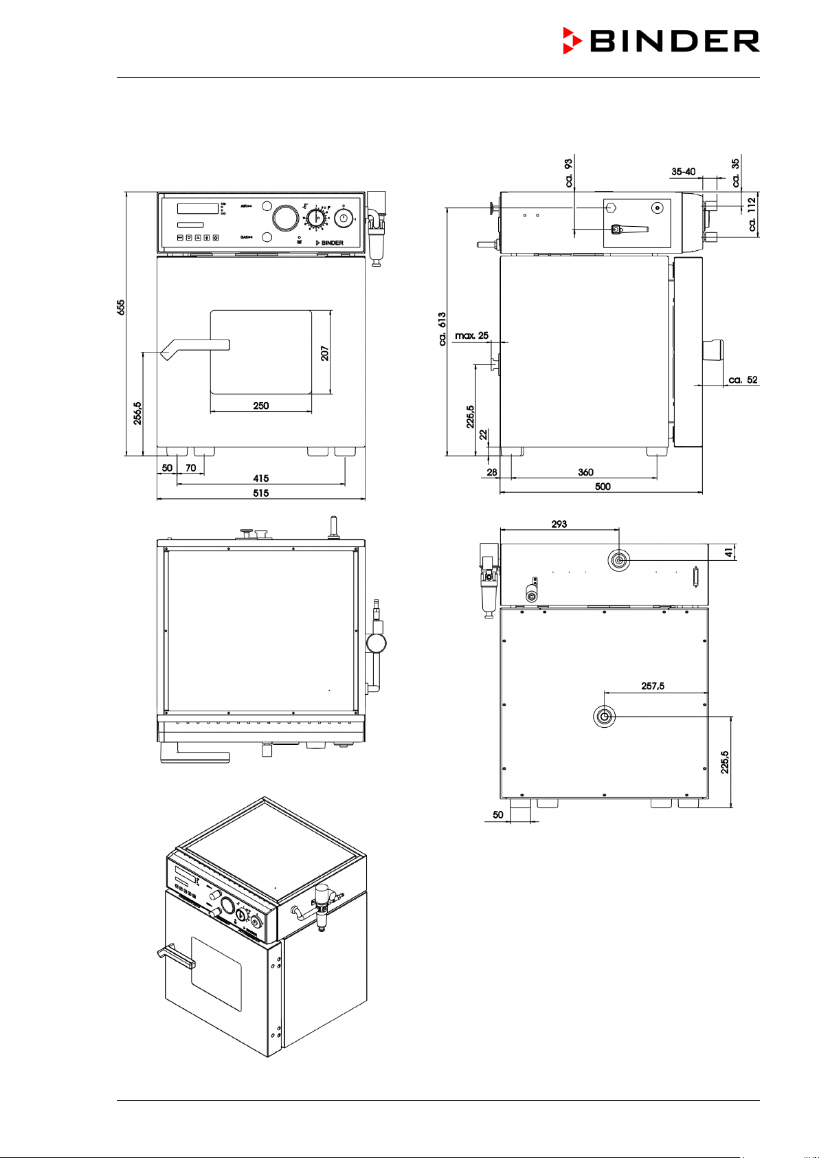
19.5 Dimensions VDL 23
VDL (E2.1) 04/2014 page 99/107
Page 100

19.6 Dimensions VDL 53
VDL (E2.1) 04/2014 page 100/107
 Loading...