

Page 1
Operating Manual
Translation of the original operating manual
VD (E3.1)
Vacuum Drying Oven
Standard: with RD4 microprocessor program controller
Optional: with MB2 microprocessor program controller
Model Model version Art. No.
VD 23 VD023-230V 9630-0001
VD 23-UL VD023UL-120V 9630-0005
VD 56 VD056-230V 9630-0002
VD 56-UL VD056UL-120V 9630-0006
VD 115 VD115-230V 9630-0003
VD 115-UL VD115UL-120V 9630-0007
BINDER GmbH
Address: Post office box 102, 78502 Tuttlingen, Germany Phone: +49 7462 2005 0
Fax: +49 7462 2005 100 Internet: http://www.b ind er -world.com
E-mail: info@binder-world.com Service Hotline: +49 7462 2005 555
Service Fax: +49 7462 2005 93 555 Service E-Mail: customerservice@binder-world.com
Service Hotline USA: +1 866 885 9794 or +1 631 224 4340 x3
Service Hotline Asia Pacif ic: +852 390 705 04 or +852 390 705 03
Service Hotline Russia and CIS: +7 495 988 15 16
Issue 10/2020 Art. No. 7001-0383
Page 2

Contents
1. SAFETY .................................................................................................................. 8
1.1 Personnel Qualification ....................................................................................................................... 8
1.2 Operating manual ................................................................................................................................ 8
1.3 Legal considerations ........................................................................................................................... 8
1.4 Structure of the safety instructions ...................................................................................................... 9
1.4.1 Signal word panel ..................................................................................................................... 9
1.4.2 Safety alert symbol ................................................................................................................... 9
1.4.3 Pictograms .............................................................................................................................. 10
1.4.4 Word message panel structure ............................................................................................... 10
1.5 Localization / position of safety labels on the chamber .................................................................... 11
1.6 Type plate.......................................................................................................................................... 11
1.7 General safety instructions on installing and operating the chamber ............................................... 12
1.8 Intended use ..................................................................................................................................... 14
1.9 Foreseeable Misuse .......................................................................................................................... 16
1.10 Residual Risks .................................................................................................................................. 16
1.11 Operating instructions ....................................................................................................................... 18
1.12 Measures to prevent accidents ......................................................................................................... 18
2. DESCRIPTION OF THE EQUIPMENT ................................................................. 19
2.1 Chamber overview ............................................................................................................................ 20
2.2 Instrument panel with regular RD4 controller.................................................................................... 21
2.3 Instrument panel with optional MB 2 contr ol ler .................................................................................. 21
2.4 Connections on the rear of the chamber ........................................................................................... 21
3. COMPLETENESS OF DELIVERY, TRANSPORTATION, STORAGE, AND
INSTALLATION .................................................................................................... 23
3.1 Unpacking, and checking equipment and completeness of delivery ................................................ 23
3.2 Guidelines for safe lifting and transportation ..................................................................................... 24
3.3 Storage .............................................................................................................................................. 24
3.4 Location of installation and ambient conditions ................................................................................ 24
4. INSTALLATION AND CONNECTIONS ............................................................... 26
4.1 Vacuum expansion racks and rack holders ...................................................................................... 26
4.2 Mounting the tilt protection holders ................................................................................................... 27
4.3 Pump module (option) ....................................................................................................................... 28
4.3.1 Pump module without pump (option) ...................................................................................... 29
4.3.2 Pump module with pump stand (option) ................................................................................. 29
4.4 Vacuum connection ........................................................................................................................... 31
4.4.1 VD connection kit for VAP1-VAP2 (option) ............................................................................. 31
4.5 Connecting inert gas supply .............................................................................................................. 32
4.6 Electrical connection ......................................................................................................................... 33
5. FUNCTIONAL OVERVIEW AND MENU STRUCTURE O F THE CONTROLLER 34
5.1 RD4 controller ................................................................................................................................... 34
5.1.1 Menu structure of the controller and access levels ................................................................ 35
5.2 MB2 controller ................................................................................................................................... 36
5.2.1 Operating functions in normal display ..................................................................................... 37
5.2.2 Display views: Normal display, program display, chart-recorder display ............................... 38
5.2.3 MB2 controller icons overview ................................................................................................ 39
5.2.4 MB2 controller operating modes ............................................................................................. 41
5.2.5 MB2 controller menu structure ................................................................................................ 41
5.2.5.1 Main menu ....................................................................................................................... 42
5.2.5.2 “Settings” submenu ......................................................................................................... 43
5.2.5.3 “Service” submenu .......................................................................................................... 43
5.2.6 Principle of controller entries .................................................................................................. 44
VD (E3.1) 10/2020 page 2/179
Page 3

Performance during and after power failures .................................................................................... 44
5.3
5.3.1 RD4 controller ......................................................................................................................... 44
5.3.2 MB2 controller ......................................................................................................................... 45
6. START UP ............................................................................................................ 45
6.1 Condition after establishing the power connection ........................................................................... 45
6.2 Standby mode: Turning on and off the vacuum drying oven ............................................................ 46
6.2.1 RD4 controller ......................................................................................................................... 46
6.2.2 MB2 controller ......................................................................................................................... 47
6.3 Controller settings upon start up ....................................................................................................... 48
6.3.1 RD4 controller ......................................................................................................................... 48
6.3.2 MB2 controller ......................................................................................................................... 48
6.4 Vacuum system ................................................................................................................................. 49
6.4.1 Evacuation .............................................................................................................................. 49
6.4.2 Ventilation after completing the drying procedure (flooding with ambient air or inert gas) ..... 50
6.4.3 Ventilation / breaking the vacuum in case of a power failure ................................................. 50
6.4.4 Operation with inert gas .......................................................................................................... 50
7. SET-POINT ENTRY .............................................................................................. 51
7.1 RD4 controller ................................................................................................................................... 51
7.1.1 Temperature set-point entry ................................................................................................... 51
7.1.2 Pressure set-point entry .......................................................................................................... 52
7.2 MB2 controller ................................................................................................................................... 52
7.2.1 Set-point entry through the “Setpoints” menu ......................................................................... 52
7.2.2 Direct setpoint entry via Normal display ................................................................................. 53
8. SETTING SPECIAL CONTROLLER FUNCTIONS .............................................. 54
8.1 Menu structure .................................................................................................................................. 54
8.1.1 RD4 controller ......................................................................................................................... 54
8.1.1.1 “Functions on/off” menu................................................................................................... 54
8.1.1.2 Quick Access menu ......................................................................................................... 55
8.1.2 MB2 controller ......................................................................................................................... 55
8.1.2.1 “Functions on/off” menu................................................................................................... 55
8.1.2.2 “Control on/off” menu ....................................................................................................... 57
8.2 Turning off the vacuum pump via the socket on the pump module .................................................. 57
8.2.1 RD4 controller ......................................................................................................................... 57
8.2.2 MB2 controller ......................................................................................................................... 58
8.3 Using the optional universal connection “GAS/AIR 2” for ventilation ................................................ 58
8.3.1 RD4 controller ......................................................................................................................... 59
8.3.2 MB2 controller ......................................................................................................................... 59
8.4 Close all valves ................................................................................................................................. 60
8.4.1 RD4 controller ......................................................................................................................... 60
8.4.2 MB2 controller ......................................................................................................................... 60
8.5 Activating / deactivating temperature control .................................................................................... 61
8.5.1 RD4 controller ......................................................................................................................... 61
8.5.2 MB2 controller ......................................................................................................................... 61
8.6 Activating / deactivating pressure control ......................................................................................... 62
8.6.1 RD4 controller ......................................................................................................................... 62
8.6.2 MB2 controller ......................................................................................................................... 63
8.7 Drying monitoring .............................................................................................................................. 64
8.7.1 RD4 controller ......................................................................................................................... 65
8.7.2 MB2 controller ......................................................................................................................... 65
9. AUTHORIZATION LEVELS AND PASSWORD PROTECTION .......................... 66
9.1 RD4 controller ................................................................................................................................... 66
9.1.1 Password request ................................................................................................................... 66
9.1.2 Assign and modify a password ............................................................................................... 66
9.1.2.1 Assign and modify the User password ............................................................................ 66
9.1.2.2 Assign and modify the Admin password ......................................................................... 67
VD (E3.1) 10/2020 page 3/179
Page 4

MB2 controller ................................................................................................................................... 68
9.2
9.2.1 User management, authorization levels and password protection ......................................... 68
9.2.2 Log in ...................................................................................................................................... 71
9.2.3 Log out .................................................................................................................................... 72
9.2.4 User change ............................................................................................................................ 72
9.2.5 Password assignment and password change ........................................................................ 73
9.2.5.1 Password change ............................................................................................................ 73
9.2.5.2 Deleting the password for an individual authorization level ............................................ 75
9.2.5.3 New password assignment for “service” or “admin” authorization level when the
password function was deactiva ted .................................................................................................. 76
9.2.6 Activation code ........................................................................................................................ 77
10. GENERAL CONTROLLER SETTINGS AND INFORMATION ............................. 78
10.1 RD4 controller ................................................................................................................................... 78
10.1.1 Selecting the controller’s menu language ............................................................................... 78
10.1.2 Selecting the temperature unit ................................................................................................ 78
10.1.3 Setting the current date........................................................................................................... 79
10.1.4 Setting the current time ........................................................................................................... 80
10.1.5 Function “Language selection at restart” ................................................................................ 80
10.1.6 Setting the chamber address .................................................................................................. 81
10.1.7 Display bright n ess ................................................................................................................... 81
10.1.8 Display of the inner chamber temperature and the heating temperature ............................... 81
10.2 MB2 controller ................................................................................................................................... 82
10.2.1 Selecting the controller’s menu language ............................................................................... 82
10.2.2 Setting date and time .............................................................................................................. 82
10.2.3 Selecting the temperature unit ................................................................................................ 84
10.2.4 Display configuration............................................................................................................... 84
10.2.4.1 Adapting the display parameters ..................................................................................... 84
10.2.4.2 Touchscreen calibration .................................................................................................. 85
10.2.5 Event lis t ................................................................................................................................. 86
10.2.6 Service contact page .............................................................................................................. 86
10.2.7 Current operating parameters ................................................................................................. 87
10.2.8 Technical chamber information ............................................................................................... 87
11. TEMPERATURE SAFETY DEVICES ................................................................... 88
11.1 Over temperature protective device class 2 (thermal switch) ........................................................... 88
11.2 Overtemperature safety controller class 2 ........................................................................................ 88
11.2.1 Safety controller mode ............................................................................................................ 88
11.2.2 Setting the safety controller .................................................................................................... 89
11.2.2.1 RD4 controller: Setting the safety controller mode .......................................................... 89
11.2.2.2 RD4 controller: Setting the safety controller value .......................................................... 89
11.2.2.3 MB2 controller ................................................................................................................. 90
11.2.3 Message and measures in the state of alarm ......................................................................... 91
11.2.3.1 RD4 controller .................................................................................................................. 91
11.2.3.2 MB2 controller ................................................................................................................. 91
11.2.4 Function check ........................................................................................................................ 92
12. TOLERANCE RANGE SETTINGS ....................................................................... 92
12.1 RD4 controller ................................................................................................................................... 92
12.1.1 Setting the delay time for temperature tolerance range alarm ............................................... 92
12.1.2 Setting the temperature tolerance range ................................................................................ 92
12.1.3 Setting the delay time for pressure tolerance range alarm ..................................................... 93
12.1.4 Setting the pressure tolerance range ...................................................................................... 93
12.1.5 State of alarm .......................................................................................................................... 93
12.2 MB2 controller ................................................................................................................................... 94
12.2.1 Setting the alarm delay times and the tolerance ra ng e s ........................................................ 94
12.2.2 Alarm condition ....................................................................................................................... 94
VD (E3.1) 10/2020 page 4/179
Page 5

13. NOTIFICATION AND ALARM FUNCTIONS ........................................................ 95
13.1 Information messages ....................................................................................................................... 95
13.1.1 RD4 controller ......................................................................................................................... 95
13.1.2 MB2 controller ......................................................................................................................... 96
13.2 Alarm messages ............................................................................................................................... 97
13.2.1 RD4 controller ......................................................................................................................... 97
13.2.2 MB2 controller ......................................................................................................................... 98
13.3 Resetting an alarm ............................................................................................................................ 99
13.3.1 RD4 controller ......................................................................................................................... 99
13.3.2 MB2 controller ......................................................................................................................... 99
13.4 Activating / deactivating the audible alarm (buzzer) ....................................................................... 100
13.4.1 RD4 controller ....................................................................................................................... 100
13.4.2 MB2 controller ....................................................................................................................... 100
14. RD4 CONTROLLER: PROGRAM START / STOP FUNCTION ......................... 101
14.1 Start time program .......................................................................................................................... 101
14.2 Start week program ......................................................................................................................... 101
14.3 Stop program .................................................................................................................................. 102
15. MB2 CONTROLLER: TIMER PROGRAM (STOPWATCH FUNCTION) ............ 103
15.1 Starting a timer program ................................................................................................................. 103
15.1.1 Performance during program delay time .............................................................................. 103
15.2 Stopping a running timer program .................................................................................................. 104
15.2.1 Pausing a running timer program ......................................................................................... 104
15.2.2 Cancelling a running timer program ...................................................................................... 104
15.3 Performance after the end of the program ...................................................................................... 104
16. MB2 CONTROLLER: TIME PROGRAMS .......................................................... 105
16.1 Starting an existing time program ................................................................................................... 105
16.1.1 Performance during program delay time .............................................................................. 106
16.2 Stopping a running time program .................................................................................................... 106
16.2.1 Pausing a running time program ........................................................................................... 106
16.2.2 Cancelling a running time program ....................................................................................... 106
16.3 Performance after the end of the program ...................................................................................... 106
16.4 Creating a new time program .......................................................................................................... 107
16.5 Program editor: program management ........................................................................................... 107
16.5.1 Deleting a time program........................................................................................................ 108
16.6 Section editor: section management ............................................................................................... 109
16.6.1 Add a new program section .................................................................................................. 110
16.6.2 Copy and insert or replace a program section ...................................................................... 110
16.6.3 Deleting a program section ................................................................................................... 111
16.7 Value entry for a program section ................................................................................................... 112
16.7.1 Section duration .................................................................................................................... 112
16.7.2 Set-point ramp and set-point step ......................................................................................... 113
16.7.3 Special controller functions ................................................................................................... 114
16.7.4 Setpoint entry ........................................................................................................................ 115
16.7.5 Tolerance range .................................................................................................................... 115
16.7.6 Repeating one or several sections within a time program .................................................... 116
16.7.7 Saving the time program ....................................................................................................... 117
17. MB2 CONTROLLER: WEEK PROGRAMS........................................................ 118
17.1 Starting an existing week program .................................................................................................. 118
17.2 Cancelling a running week program ............................................................................................... 118
17.3 Creating a new week program ........................................................................................................ 119
17.4 Program editor: program management ........................................................................................... 120
17.4.1 Deleting a week program ...................................................................................................... 121
17.5 Section editor: section management ............................................................................................... 122
17.5.1 Add a new program section .................................................................................................. 123
17.5.2 Copy and insert or replace a program section ...................................................................... 123
17.5.3 Deleting a program section ................................................................................................... 124
VD (E3.1) 10/2020 page 5/179
Page 6

Value entry for a program section in the Section view .................................................................... 124
17.6
17.6.1 Set-point ramp and set-point step modes ............................................................................. 124
17.6.2 Weekday ............................................................................................................................... 125
17.6.3 Start time ............................................................................................................................... 125
17.6.4 Setpoint entry ........................................................................................................................ 125
17.6.5 Special controller functions ................................................................................................... 126
18. NETWORK AND COMMUNICATION ................................................................ 126
18.1 RD4 controller: Ethernet network settings ...................................................................................... 126
18.1.1 Showing the network settings ............................................................................................... 126
18.1.1.1 Showing the chamber’s MAC address .......................................................................... 126
18.1.1.2 Showing the IP address................................................................................................. 127
18.1.1.3 Showing the subnet mask ............................................................................................. 127
18.1.1.4 Showing the standard gateway ..................................................................................... 127
18.1.1.5 Showing the DNS server address ................................................................................. 128
18.1.1.6 Showing the DNS chamber name ................................................................................. 128
18.1.2 Changing the configuration of the network settings .............................................................. 128
18.1.2.1 Selecting the type of IP address assignment (automatic / manual) .............................. 129
18.1.2.2 Selecting the type of assignment of the DNS server address (automatic / manual) ..... 129
18.1.2.3 Assigning the IP address ............................................................................................... 129
18.1.2.4 Setting the subnet mask ................................................................................................ 130
18.1.2.5 Setting the standard gateway ........................................................................................ 131
18.1.2.6 Assigning the DNS server address ............................................................................... 131
18.2 MB2 controller ................................................................................................................................. 132
18.2.1 Ethernet ................................................................................................................................ 132
18.2.1.1 Configuration ................................................................................................................. 132
18.2.1.2 Display of MAC address ................................................................................................ 133
18.2.2 Web server ............................................................................................................................ 133
18.2.3 E-Mail .................................................................................................................................... 134
19. RD4 CONTROLLER: DATA RECORDER ......................................................... 135
19.1 Recorded data ................................................................................................................................. 135
19.2 Storage capacity ............................................................................................................................. 135
19.3 Setting the storage rate for the “DL1” recorder data ....................................................................... 136
19.4 Deleting the data recorder............................................................................................................... 136
20. USB MENU: DATA TRANSFER VIA USB INTERFACE ................................... 136
20.1 RD4 controller ................................................................................................................................. 136
20.1.1 Connecting the USB stick ..................................................................................................... 137
20.1.2 Import function ...................................................................................................................... 137
20.1.3 Export functions .................................................................................................................... 137
20.1.4 Ongoing data transfer ........................................................................................................... 138
20.1.5 Error during data transmission .............................................................................................. 138
20.1.6 Removing the US B stick ....................................................................................................... 138
20.2 MB2 controller ................................................................................................................................. 138
21. MB2 CONTROLLER: CHART RECORDER DISPLAY ...................................... 140
21.1 Views ............................................................................................................................................... 140
21.1.1 Show and hide legend .......................................................................................................... 140
21.1.2 History display ....................................................................................................................... 140
21.2 Setting the parameters .................................................................................................................... 143
22. REFERENCE MEASUREMENTS ...................................................................... 144
22.1 Checking the temperature in the inner chamber ............................................................................. 144
22.1.1 Checking the controller display ............................................................................................. 144
22.1.2 Checking the spatial temperature exactitude ....................................................................... 144
23. OPTIONS ............................................................................................................ 145
23.1 APT-COM™ 4 Multi Management software (Option) ..................................................................... 145
VD (E3.1) 10/2020 page 6/179
Page 7

Analog outputs for temperature and pressure (option) ................................................................... 145
23.2
23.3 Measuring access port for vacuum, 9 poles (option) ...................................................................... 145
23.4 Object temperature display with flexible Pt 100 temperature sensor (option) ................................ 146
23.4.1 Connection of the object temperature sensor ....................................................................... 146
23.4.2 Display on the RD4 controller ............................................................................................... 147
23.4.3 Display on the MB2 controller ............................................................................................... 147
23.5 LED interior lighting ......................................................................................................................... 147
24. CLEANING AND DECONTAMINATION ............................................................ 148
24.1 Cleaning .......................................................................................................................................... 148
24.2 Decontamination / chemical disinfection ......................................................................................... 149
25. MAINTENANCE AND SERVICE, TROUBLESHOOTING, REPAIR, TESTING . 151
25.1 General information, personnel qualification................................................................................... 151
25.2 Simple troubleshooting .................................................................................................................... 151
25.3 Maintenance intervals, service ........................................................................................................ 154
25.4 Service Reminder ............................................................................................................................ 154
25.4.1 RD4 controller ....................................................................................................................... 154
25.4.2 MB2 controller ....................................................................................................................... 155
25.5 Sending the chamber back to BINDER GmbH ............................................................................... 155
26. DISPOSAL.......................................................................................................... 156
26.1 Disposal of the transport packing .................................................................................................... 156
26.2 Decommissioning ............................................................................................................................ 156
26.3 Disposal of the chamber in the Federal Republic of Germany ....................................................... 157
26.4 Disposal of the chamber in the member states of the EU except for the Federal Republic of
Germany.......................................................................................................................................... 158
26.5 Disposal of the chamber in non-member states of the EU ............................................................. 159
27. TECHNICAL DESCRIPTION .............................................................................. 160
27.1 Factory calibration and adjustment ................................................................................................. 160
27.2 Over current protection ................................................................................................................... 160
27.3 VD / VD-UL technical data .............................................................................................................. 160
27.4 Equipment and options (extract) ..................................................................................................... 162
27.5 Accessories and spare parts (extract) ............................................................................................ 163
27.6 Dimensions...................................................................................................................................... 165
27.6.1 VD 23 .................................................................................................................................... 165
27.6.2 VD 56 .................................................................................................................................... 166
27.6.3 VD 115 .................................................................................................................................. 167
28. CERTIFICATES AND DECLARATIONS OF CONFORMITY ............................. 168
28.1 EU Declaration of Conformity.......................................................................................................... 168
28.2 Certificate for the GS mark of conformity of the “Deutsche Gesetzliche Unf al lver si c herung e.V .”
(German Social Accident Insurance) DGUV ................................................................................... 171
29. PRODUCT REGISTRATION .............................................................................. 173
30. CONTAMINATION CLEARANCE CERTIFICATE ............................................. 174
30.1 For chambers located outside USA and Canada ........................................................................... 174
30.2 For chambers located in USA and Canada .................................................................................... 177
VD (E3.1) 10/2020 page 7/179
Page 8
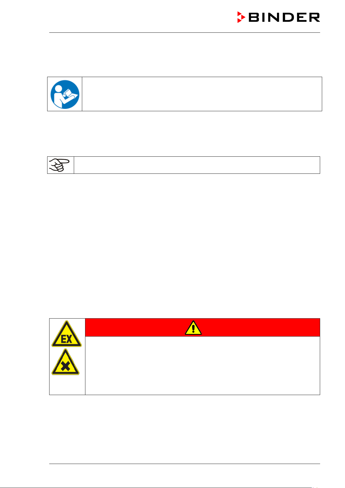
Dear customer,
For the correct oper ation of the chamber, it is important that you read this operating manual completel y
and carefully and observe all instructions as indicated. Failure to read, understand and follow the
instructions may result in personal injury. It can also lead to damage to the chamber and/or poor
equipment performance.
1. Safety
1.1 Personnel Qualification
The chamber m ust only be installed, tested, and start ed up by personn el qualified f or assembl y, startup,
and operation of the chamber. Qualified personnel are persons whose professional education,
knowledge, experience an d k nowledge of rele vant stan dards allow th em to assess, car ry out, and ide ntif y
any potential hazards in the work assigned to them. T hey must hav e been tra ined and instructe d, and be
authorized, to work on the chamber .
The chamber should only be operated by laboratory personnel especially trained for this purpose and
familiar with all precautionary measures required for working in a laboratory. Observe the national
regulations on minimum age of laboratory personnel.
1.2 Operating manual
This operating m anual is part of the com ponents of delivery. Alwa ys keep it handy for refer ence in the
vicinity of the chamber. If selling the unit, hand over the operating manual to the purchaser.
To avoid injuries and damage obs erve the safety instructions of the opera ting manual. Failure to follow
instructions and safety precautions can lead to significant risks.
DANGER
Dangers due to failure to observe the ins truc tions and safety precautions.
Serious injuries and chamber damage. Risk of death.
Observe the safety instructions in this Operating Manual.
Follow the operating procedures in this Operating Manual.
Carefully read the complete operating instructions of the chamber prior to installing and
using the chamber.
Keep the operating manual for future reference
Make sure that all persons who use the chamber and its associated work equipment have
read and understood the Operating Manual.
This Operating Manu al is supplem ented and updated as needed. Al ways use the m ost recent version of
the Operating Manual. When in doubt, call the BINDER Service Hotline for information on the up-todateness and validity of this Operating Manual.
1.3 Legal considerations
This operating manual is for informational purposes only. It contains information for correct and safe
installing, start-up, operation, decommissioning, cleaning and maintenance of the product. Note: the
contents and the product descr ibed are subj ect to cha nge with out not ice.
Understanding and obs erving the instructions in this oper ating manual are prerequisites f or hazard-free
use and safety dur ing oper ation and m ainte nance. Im ages are to pro vide basic under stan ding. The y ma y
deviate from the actual version of the chamber. The actual scope of delivery can, due to optional or
special design, or due to re cent technical cha nges, devi ate from the inform ation and illustr ations in these
instructions this op erating manual. In no event shall BINDER be held liable for any dam ages, direct or
incidental arising out of or related to the use of this manual.
VD (E3.1) 10/2020 page 8/179
Page 9
This operating manual ca nnot cover all conc eivable applicat ions. If you would like additional inf ormation,
or if special problem s arise that are not suf ficiently addressed in th is manual, please ask your dealer or
contact us directly by phone at the number located on page one of this manual
Furthermore, we emphasize that the contents of this operating manual are not part of an earlier or
existing agreement, description, or legal relationship, nor do they modify such a relationship. All
obligations on the part of BINDER derive f rom the respective p urchase contract, which also contains the
entire and exclusively valid statement of warranty administr ati on and t he g en er al t erm s and c ond iti ons, as
well as the legal regulati ons valid at the time the contract is conc luded. The statements in this manual
neither augment nor restrict the contractual warranty provisions.
1.4 Structure of the safety instructions
In this operating manual, the following safety definitions and symbols indicate dangerous situations
following the harmonization of ISO 3864-2 and ANSI Z 535. 6.
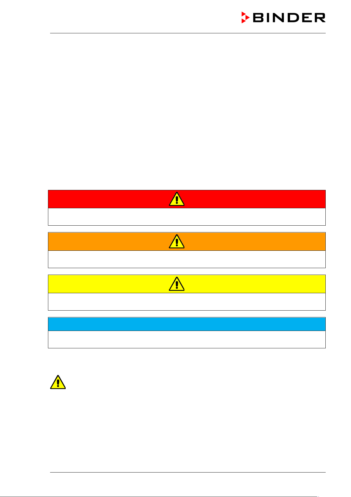
1.4.1 Signal word panel
Depending on the probability of serious consequences, potential dangers are identified with a signal
word, the corresponding safety color, and if appropriate, the safety alert symbol.
DANGER
Indicates an imminently hazardous situation that, if not avoided, will result in death or serious
(irreversible) injury.
WARNING
Indicates a potentially hazardous situation which, if not avoided, could result in death or serious
(irreversible) injury.
CAUTION
Indicates a potentially hazardous situation which, if not avoided, may result in moderate or minor
(reversible) injury.
NOTICE
Indicates a potentially hazardous situation which, if not avoided, may result in damage to the product
and/or its functions or of a property in its proximity.
1.4.2 Safety alert symbol
Use of the safety alert symbol indicates a risk of injury.
Observe all measures that are marked with the safety alert symbol in order to avoid death or
injury.
VD (E3.1) 10/2020 page 9/179
Page 10
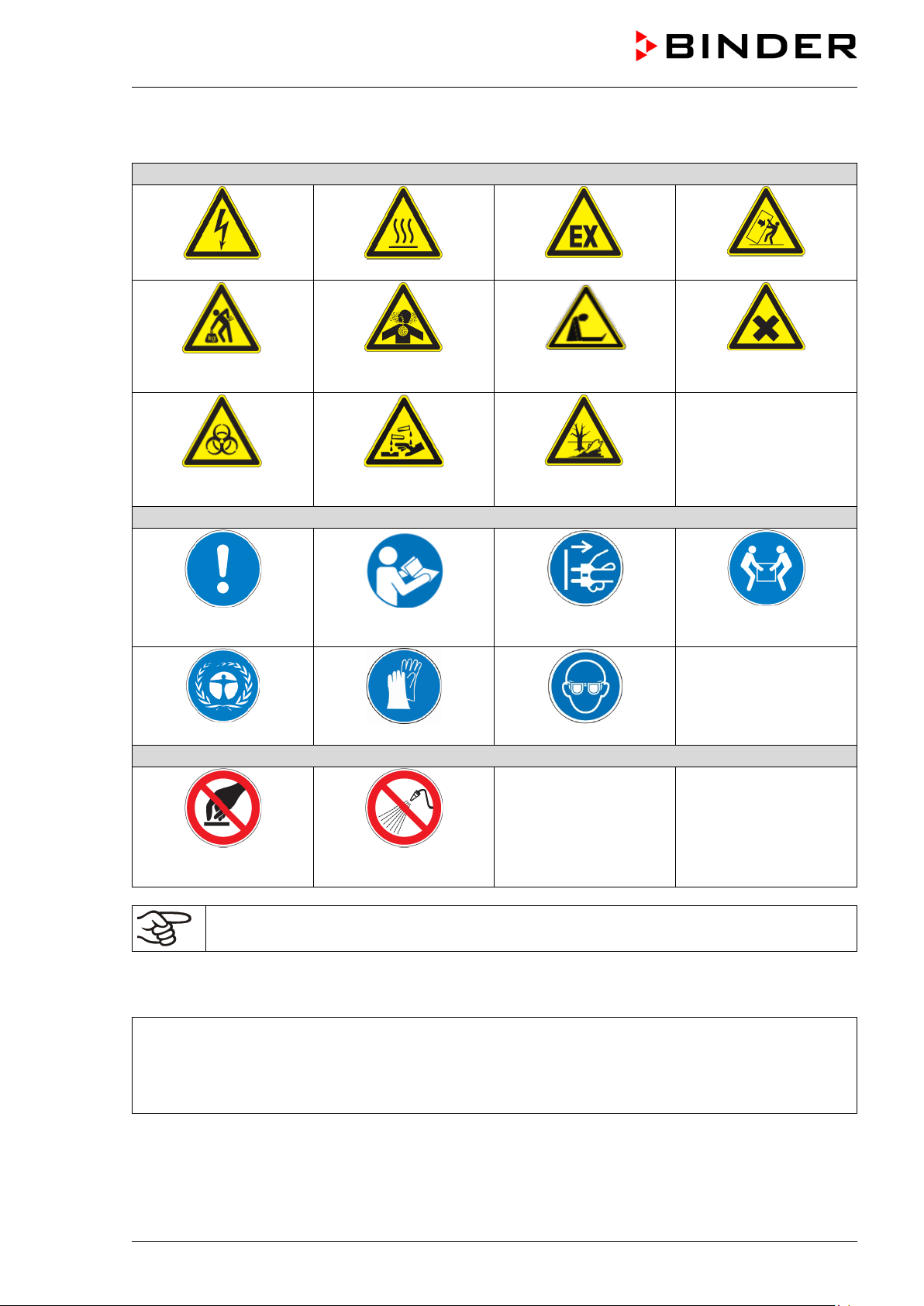
Warning signs
Electrical hazard
Hot surface
or chemical burns
Mandatory action signs
instructions
plug
Wear protective gloves
Wear safety goggles
Prohibition signs
water
1.4.3 Pictograms
Lifting hazard
Biohazard
Mandatory regulation
Inhalation hazard
Risk of corrosion and /
Read operating
Explosive atmosphere
Suffocation hazard
Pollution Hazard
Disconnect the power
Stability hazard
Harmful substances
Lift with several persons
Environment protection
Do NOT touch
Information to be observed in order to ensure optimum function of the product.
Do NOT spray with
1.4.4 Word message panel structure
Type / cause of hazard.
Possible consequences.
∅ Instruction how to avoid the hazard: prohibition
Instruction how to avoid the hazard: mandatory action
Observe all other n otes and inform ation not necessarily em phasized in the s ame way, in order to avoid
disruptions that could result in direct or indirect injury or property damage.
VD (E3.1) 10/2020 page 10/179
Page 11
Pictograms (Warning signs)
Service label
safety labels that are no longer
legible. Contact BINDER Service for these
Indications of the type plate (example)
Information
BINDER
Manufacturer: BINDER GmbH
VD 115
Model designation
Vacuum Drying Oven
Device name
Serial No.
000000000000
Serial no. of the chamber
Built
2020
Year of construction
220 °C
428 °F
IP protection
20
IP type of protection acc. to standard EN 60529
Nominal temp.
220 °C
1,60 kW / 7,0 A
428 °F
230 V / 50 Hz
IP protection
20
230 V / 60 Hz
Safety device
DIN 12880
1 N ~
Class
2.0
Art. No.
9630-0003
Project No.
Built
2020
Vacuum Drying Oven
BINDER GmbH
www.binder-world.com
VD 115
Serial No. 00000000000000
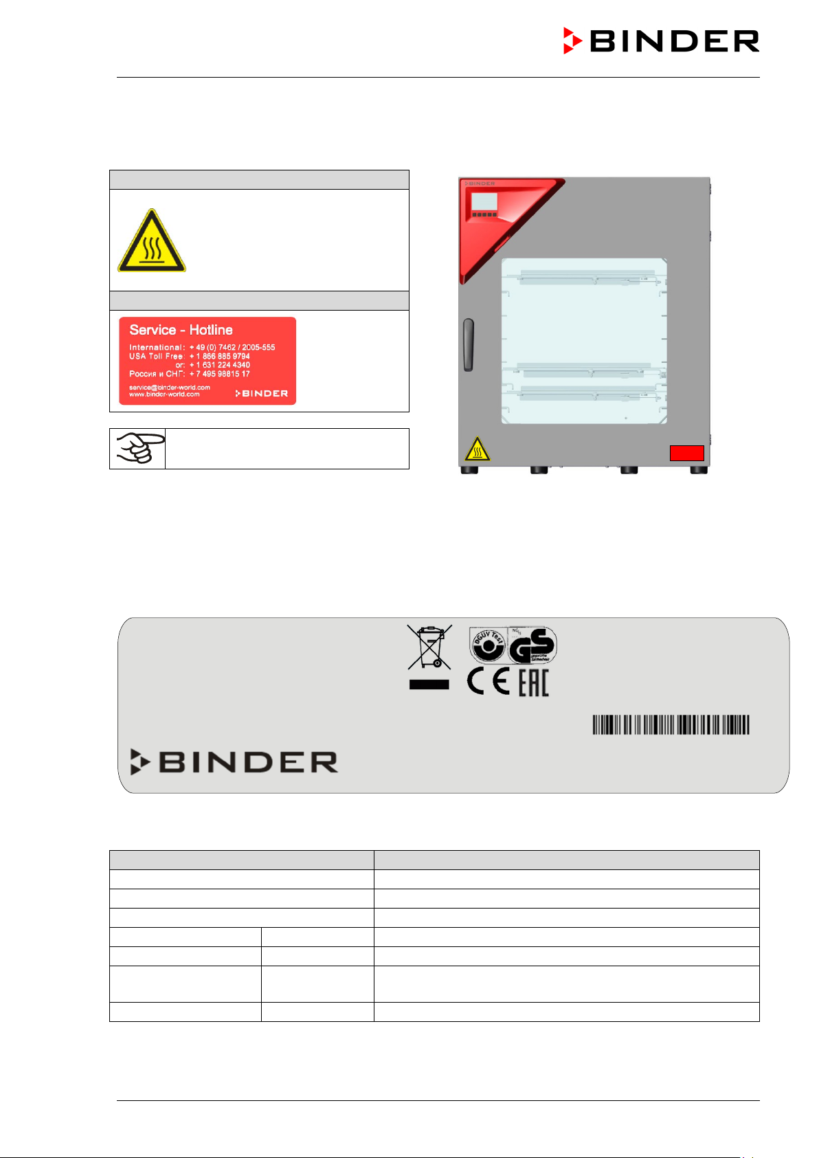
1.5 Localization / position of safety labels on the chamber
The following labels are located on the chamber:
Hot surface
(on the outer chamber door)
Keep safety labels complete and
legible.
Replace
replacements.
Figure 1: Position of labels on the chamber (example:
regular chamber with RD4 controller)
1.6 Type plate
The type plate sticks to the left side of the chamber, bottom right-hand.
Im Mittleren Ösch 5
78532 Tuttlingen / Germany
Figure 2: Type plate (exam ple of VD 115)
E3.1
Made in Germany
Nominal temperature
VD (E3.1) 10/2020 page 11/179
Nominal temperature
Page 12
Indications of the type plate (example)
Information
Temp. safety device
DIN 12880
Temperature safety device acc. to standard DIN
12880:2007
Class
2.0
Class of temperature safety device
Art. No.
9630-0003
Art. no. of the chamber
Project No.
---
Optional: Special application acc. to project no.
1,60 kW
Nominal power
7,0 A
Nominal current
230 V / 50 Hz
230 V / 60 Hz
1 N ~
Current type
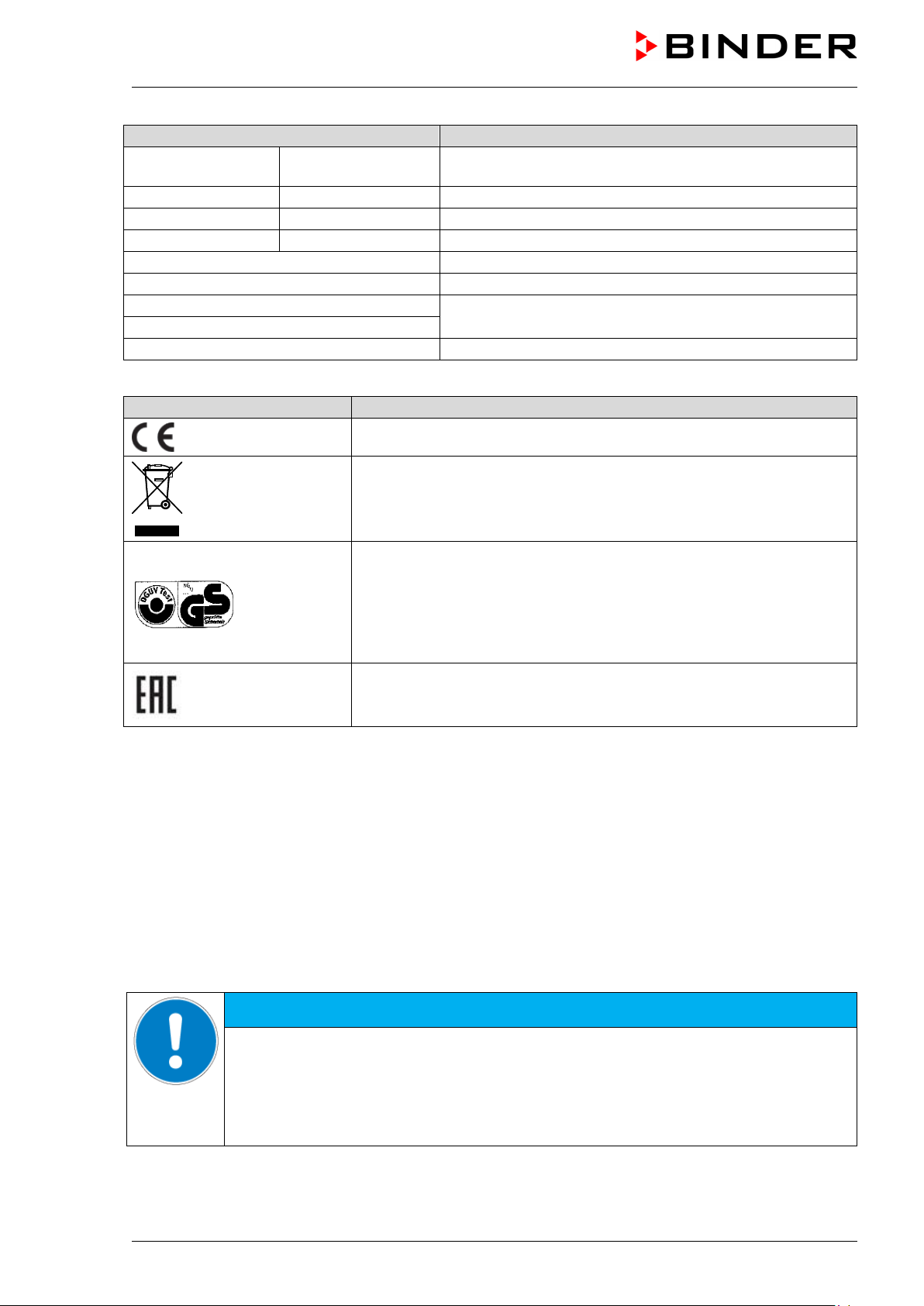
Symbol on the type plate
Information
Nominal voltage +/- 10% at the indicated power frequency
CE conformity marking
Electrical and electronic equipment manufactured / placed on the
market in the EC after 13 August 2005 and to be disposed of in a
separate collection according to Directive 2012/19/EU on waste
electrical and electronic equipment (WEEE).
GS mark of conformity of the “Deutsche Gesetzliche
Unfallversicherung e.V. (DGUV), Prüf- und Zertifizierungsstelle
Nahrungsmittel und Verpackung im DGUV Test” (German Social
Accident Insurance (DGUV), Testing and Certification Body for
Foodstuffs and Packaging Industry in DGUV Test).
(Not valid for UL chambers)
The chamber is certified according to Customs Union Technical
Regulation (CU TR) for the Eurasian Economic Union (Russia,
Belarus, Armenia, Kazakhstan Kyrgyzstan).
1.7 General safety instructions on installing and operating the chamber
With regard to operating the chamber and to the installation location, please observe the DGUV
guidelines 213-850 on safe working in laboratories, issued by the employers’ liability insurance
association (for Germany).
BINDER GmbH is only respons ible for the safet y features of the chamber provided sk illed electricians or
qualified personnel authorized by BINDER perform all maintenance and repair, and if components
relating to chamber safety are replaced in the event of failure with original spare parts.
To operate the chamber, use only original BINDER ac cessories or ac cessories f rom third-party suppliers
authorized by BINDER. The user is responsible for any risk caused by using unauthorized accessories.
Danger of overheating due to lack of ventilation.
Damage to the chamber.
∅ Do NOT install the chamber in unventilated recesses.
Ensure sufficient ventilation for dispersal of the heat.
Observe the prescribed minimum distances when installing the chamber (chap. 3.4)
VD (E3.1) 10/2020 page 12/179
NOTICE
Page 13
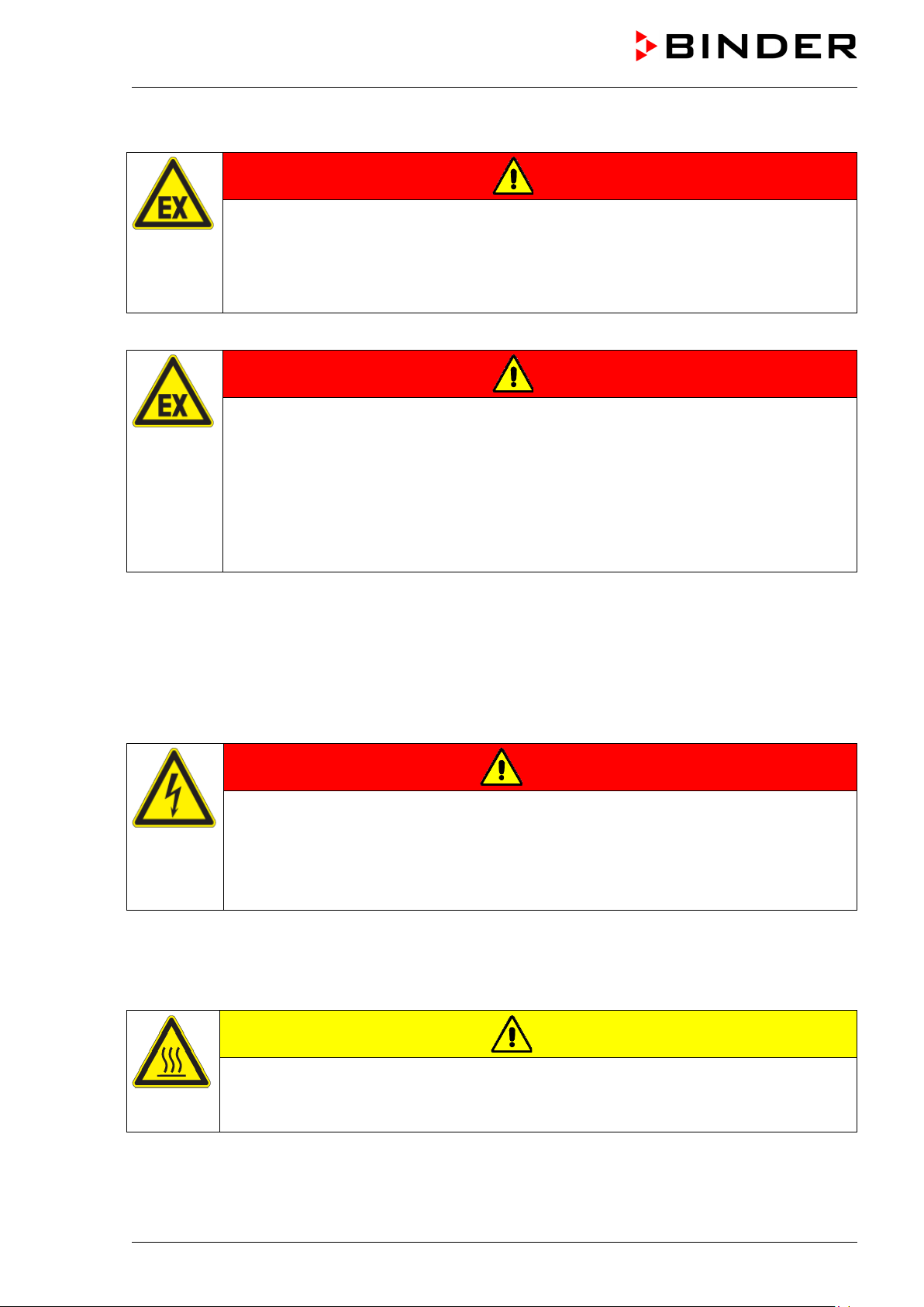
Do not install or operate the vacuum drying oven VD in potentially explosive areas.
DANGER
Danger of explosion due to combustible du sts or explosive mixtures in the vicinity
of the equipment.
Serious injury or death from burns and / or explo sion pressure.
Do NOT operate the equipment in potentially explosive areas.
KEEP combustible dust or air-solvent mixtures AWAY from the equipment.
The chamber does not dispose of any measures of explosion protection.
DANGER
Danger of explosion due to introduction of flammable or explosive substances in
the chamber.
Serious injury or death from burns and / or explo sion pressure.
∅ Do NOT introduce any substance into the chamber which is combustible or explosive at
working temperature.
∅ Do NOT introduce any combustible dust or air-solvent mixture in the inner chamber.
∅ Do NOT use the vacuum drying oven for drying or heat treatments leading to release of
combustible vapors able to form an explosive mixture with air.
Any solvent contained in th e charging material m ust not be explosive or inflam mable. I.e., irres pective of
the solvent concentration in the steam room, NO explosive mixture with air must form. The drying
temperature must lie below the flash point or below the sublimation point of the charging material.
Familiarize yourself with the physical and chemical properties of the charging material, as well as the
contained moisture constituent and its behavior with the addition of heat energy and changes in pressure.
Familiarize yourself with any potential health risks caused by the charging material, the contained
moisture constituent or by reaction products that may arise during the drying process. T ake adequate
measures to exclude such risks prior to putting the chamber into operation.
DANGER
Electrical hazard by water entering the chamber.
Deadly electric shock.
∅ The chamber must NOT become wet during operation, cleaning, or maintenance.
∅ Do NOT install the chamber in damp areas or in puddles.
Set up the chamber in a splash-proof manner.
The chambers were produced in accordance with the relevant VDE re gulations and were routin ely tested
in accordance to VDE 0411-1 (IEC 61010-1).
During and shortl y after operation, t he tem perature of the i nner surf aces alm ost equals the set -point. The
inner chamber will become hot during operation.
CAUTION
Danger of burning when touching the inner surfaces during operation.
Burns.
∅ Do NOT touch the inner surfaces or the charging material during and after operation.
VD (E3.1) 10/2020 page 13/179
Page 14
In the case of operation with inert gas, the chamber is supplied with an oxygen-displ acing gas (e.g. N
The gas emerging fr om the system m ust therefore be rem oved from the install ation area by means of a
suitable extraction s ystem (see technical ventilation measures in the DGUV g uidelines 213-850 on safe
working in laboratories, issued b y the em plo yers’ liab il it y insuranc e ass oci ati on (f or Germany).
With use of a vacuum system or a vacuum pump, observe the permitted gas inlet
temperature. Observe the safety instructions of the pump manufacturer.
).
2
1.8 Intended use
Observing the instructions in this operating manual and conducting regular maintenance work
(chap. 24) is part of the intended use.
Any use of the chambers that does not comply with the requirements specified in this Operating
Manual shall be considered improper use.
Other applications than those described in this chapter are not approved.
Use
The VD vacuum dr ying ovens are suitable for drying and heat treatment of solid or pulverized chargi ng
material, as well as bulk material, using the supply of heat under vacuum.
Requirements for the chamber load
Any sol vent content must not be explos ive or flammabl e. A mixture of any component of the charging
material with air mus t NOT be explosive. The dr ying temperature m ust lie below the flas h point or below
the sublimation po int of the c har gi ng material. Any com ponent of the charging mater ia l must NOT be able
to release toxic gases.
The loading material shall not contain any corrosive ingredients that may damage the machine
components made of stainless steel and aluminum. Such ingredients include in particular acids and
halides. Any corrosive damage caused by such ingredients is excluded from liability by BINDER GmbH.
The chamber does not dispose of any measures of explosion protection.
DANGER
Explosion or implosion hazard and danger of poisoning through the introduction of
unsuitable loading material.
Poisoning. Serious injury or death from burns and / or explosion pressure.
∅ Do NOT introduce any substance combustible or explosive at working temperature into
the chamber, in particular no energy sources such as batteries or lithium-ion batteries.
∅ Do NOT introduce explosive dust or air-solvent mixture into the inner chamber.
∅ Do NOT introduce any substance which could lead to release of toxic gases.
VD (E3.1) 10/2020 page 14/179
Page 15
Contamination of the chamber by toxic, infectious or radioactive substances must be prevented
WARNING
Danger of intoxication and infection through contamination of the chamber with
toxic, infectious or radioactive substances.
Damages to health.
Protect the interior of the chamber from contamination by toxic, infectious or radioactive
substances.
Take suitable protective measures when introducing and removing toxic, infectious or
radioactive material
In case of foreseeable use of the chamber there is no risk for the user through the integration of the
chamber into systems or by special environm ental or operating conditions in the sense of EN 610101:2010. For this, the intended use of the chamber and all its connections must be observed.
Medical devices
The chambers are not classified as medical devices as defined by the Medical Device Directive
93/42/EEC.
Due to the special demands of the Medical Device Directive (MDD), these chambers are not
qualified for sterilization of medical devices as defined by the directive 93/42/EWG.
Personnel Requirements
Only trained person nel with knowledge of the Oper ating Ma nual can s et up and install the c ham ber, start
it up, operate, clean, and take it out of operation. Service and repairs call for further technical
requirements (e.g. electrical know-how), as well as knowledge of the service manual.
Installation site requirements
The chambers are designed for setting up inside a building (indoor use).
The requirements des cribed in the Operating M anual for installation site and ambient conditions (Chap .
3.4) must be met.
VD (E3.1) 10/2020 page 15/179
Page 16

1.9 Foreseeable Misuse
Other applications than those described in chap. 1.8 are not approved.
This expressly incl udes the following misuses ( the list is not exhaustive), which p ose risks despite the
inherently safe construction and existing technical safety equipment:
• Non-observance of Operating Manual
• Non-observance of information and warnings on the chamber (e.g. control unit messages, safety
identifiers, warning signals)
• Installation, startup, operation, maintenance and repair by untrained, insufficiently qualified, or
unauthorized personnel
• Missed or delayed maintenance and testing
• Non-observance of traces of wear and tear
• Insertion of materials excluded or not permitted by this Operating Manual.
• Non-compliance with the admissible parameters for processing the respective material.
• Installation, testing, service or repair in the presence of solvents
• Installation of replacement parts and use of accessories and operating resources not specified and
authorized by the manufac turer
• Installation, startup, operation, maintenance or repair of the chamber in absence of operating
instructions by the operator
• Bypassing or c han gin g pr ot ec tive systems, operation of the c hamber without the designated pr otec t ive
systems
• Non-observance of messages regarding cleaning and disinfection of the chamber.
• Spilling water or cleaning agent on the c ham ber, water penetrat ing into the c hamber dur ing operat ion,
cleaning or maintenance.
• Cleaning activity while the chamber is turned on.
• Operation of the chamber with a damaged housing or damaged power cord
• Continued operation of the chamber during an obvious malfunction
• Insertion of objects, particularly metallic objects, in louvers or other openings or slots on the chamber
• Human error (e.g. insufficient experience, qualification, stress, exhaustion, laziness)
To prevent these and other risks fr om incorrect operati on, the operator s hall issue operating instruc tions.
Standard operating procedures (SOPs) are recommended.
1.10 Residual Risks
The unavoidable design f eatures of a chamber, as well as its proper f ield of application, can also pose
risks, even during corr ect operation. These residual risk s include hazards which, despite the inher ently
safe design, existing technical protective equipment, safety precautions and supplementary protective
measures, cannot be ruled out.
Messages on the chamber and in the Operating Manual warn of residual risks. The consequences of
these residual risks and the measures required to prevent them are listed in the Operating Manual.
Moreover, the operator m ust take measures to minimize hazards from unavoidable residual risks. This
includes, in particular, issuing operating instructions.
The following list s ummarizes the hazar ds against which this Operating Manua l and the Service Manual
warn, and specifies protective measures at the appropriate spots:
VD (E3.1) 10/2020 page 16/179
Page 17

Unpacking, Transport, Installati on
• Sliding or tilting the chamber
• Setup of the chamber in unauthorized areas
• Installation of a damaged chamber
• Installation of a chamber with damaged power cord
• Inappropriate site of installation
• Missing protective conductor connection
Normal operation
• Assem bly errors
• Contact with hot surfaces on the housing
• Contact with hot surfaces in the interior and inside of doors
• Emission of non-ionizing radiation from electrical operating resources
• Contact with live parts in normal state
Cleaning and Decontamination
• Penetration of water into the chamber
• Inappropriate cleaning and decontamination agents
• Enclosure of persons in the interior
Malfunction and Damage
• Continued operation of the chamber during an obvious malfunction or outage of the heating or the
vacuum system
• Contact with live parts during error status
• Operation of a unit with damaged power cord
Maintenance
• Maintenance wor k on live parts.
• Execution of maintenance work by untrained/insufficiently qualified personnel
• Electrical safety analysis during annual maintenance not performed
Trouble-shooting and Repairs
• Non-observance of warning messages in the Service Manual
• Trouble-shooting of live parts without specified safety measures
• Absence of a plausibility check to rule out erroneous inscription of electrical components
• Performance of repair work by untrained/insufficiently qualified personnel
• Inappropriate repairs which do not meet the quality standard specified by BINDER
• Use of replacement parts other than BINDER original replacement parts
• Electrical safety analysis not performed after repairs
VD (E3.1) 10/2020 page 17/179
Page 18

1.11 O perating instructions
Depending on the applicati on and l ocation of the c ham ber, the operat or of th e cham ber mus t provide th e
relevant information for safe operation of the chamber in a set of operating instructions.
Keep these operating instructions with the chamber at all times in a place where they are
clearly visible. They must be comprehensible and written in the language of the employees.
1.12 Measures to prevent accidents
The manufacturer took the follo wing m eas ures to prevent ign iti on and ex plos io ns :
• Indications on the type plate
See operating manual chap. 1.6.
• Operating manual
An operating manual is available for each chamber.
• Overtemperature monitoring
The chamber is equipped with a temperature display, which can be read from outside.
The chamber is equipped with an additional safety controller (temperature safety device class 2 acc. to
DIN 12880:2007). Visual and audible (buzzer) signals indicate temperature exceeding.
• Safety, measurement, and control equipment
The safety, measuring, and control equipment is easily accessible.
• Electrostatic ch arg e
The interior parts are grounded.
• Non-ionizing radiation
Non-ionizing radiation is not intentionally produced, but released only for technical reasons by
electrical equipm ent (e.g. electric motors, po wer cables, solenoids) . The machine has no perm anent
magnets. If persons with active implants (e.g. pacemakers, defibrillators) keep a safe distance
(distance of field sour ce to i mplant) of 30 cm, an influenc e of thes e implants can be excluded with h ig h
probability.
• Protection against touchable surfaces
Tested according to EN ISO 13732-1:2008.
• Floors
See operating manual chap. 3.4 for correct installation
• Cleaning
See operating manual chap. 24.
• Examinations
The chamber has been inspected by the “Deutsche Gesetzliche Unfallversicherung e.V. (DGUV)
(German Social Accident Insurance (DGUV)” (German Social Accident Insurance (DGUV), Testing
and Certification Body for Foodstuffs and Packaging Industry i n DGUV Tes t) and bear s the GS m ark.
(Not valid for UL chambers)
VD (E3.1) 10/2020 page 18/179
Page 19

2. Description of the equipm e nt
Vacuum drying is used f or special dr ying problem s, for whic h conventio nal drying methods cannot off er a
solution due to physical limitations.
Controller
The chambers are equipped with a multifunctional microprocessor display controller with 2-channel
technology for tem perat ure and pr es sur e. Temperature is indicated accur ate to o n e-tenth of a degree, the
pressure inside the cham ber accur ate to on e 1 m bar. Pres sure is m easured b y a firmly installed pressure
sensor.
Standard RD4 controller: The chamber is regularly equipped with the RD4 controller. This efficient
chamber controller is equipped with a m ultitude of operatin g functions, in add ition to recorder and a larm
functions. Set-point entr y is easily accom plished directly via the chamber contr oller and is also pos sible
directly with a computer via Intranet in connection with the optional APT-COM™ 4 Multi Management
Software (option, chap. 23.1).
Option MB2 controller: T he chamber is optionally available with the MB2 display program controller.
This efficient program controller is equipped with a multitude of operating functions, in addition to recorder
and alarm functions. Programming of test cycles is easily accomplished via the modern MB2 touch
screen controller and is also possible directly with a computer via Intranet in connecti on with the APTCOM™ 4 Multi Management Software (option, chap. 23.1).
The chamber com es equipped with an Ethernet serial in terface for computer communication and with a
USB interface. In ad dition, the BINDER APT-COM™ 4 Multi Management Software permits networking
up to 100 chambers and c onnecting them to a PC for controlling an d programm ing, as well as recording
and representing temperature and pressure data. For further options, see chap. 23.
Material
The inner cham ber is made of especially corros ion resistant stainless steel V4A (German material no.
1.4404, US equivalent AISI 316L) micro-polished. The rack holder and all of the chamber's vacuum
connections and valves ar e made of especially corro sion resistant stainless steel V4A (German mater ial
no. 1.4571, US equiv alent AISI 316T i). The housing is RAL 703 5 powder-coated. All c orners and edges
are also completely coate d. W hen operating the chamber at tem peratures above 150 °C / 302 °F, the
impact of the oxygen in t he air m ay cause discol oratio n of the m etallic surfac es (yellowish-br own or b lue)
by natural oxidatio n processes. T hese colorations are harm less and will in n o way impair the function or
quality of the chamber.
The chambers are jacket-heated. The preheating chamber technique ensures a completely
homogeneous jack et temperature, ensuring uniform heat transfer into th e inner chamber. The low-loss
heat transfer to the material uses the aluminum vacuum expansion racks (or optionally available in
stainless steel). The elastic-mounted safety glass window reliably compensates any overpressure or
explosions that may occur. The additional laminated safety glass pane ensures proven and effective
splinter protection in the event of an implosion.
The chambers provide a universal connection for inert gas / ambient air and a measuring connection
serving to connect a measuring access port.
All installable items, such as racks and rack holders, can be easily removed. The completely smooth
inner chamber with its rounded corners and internally welded seams is easy to clean.
The minimum working temperature of the vacuum drying oven is approx. 10 °C / 18 °F above room
temperature. The maximum temperature is 220 °C / 428 °F.
3
Vacuum pumps with a suction capacity of 1 m
VD (E3.1) 10/2020 page 19/179
/h to 30 m3/h are suitable for the VD vacuum drying oven.
Page 20
(A)
(A)
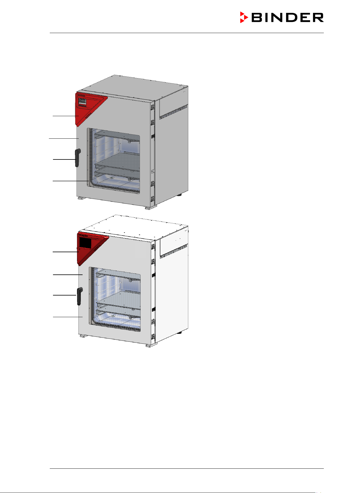
2.1 Chamber overview
(B)
(C)
(D)
(B)
(C)
(D)
Figure 3: VD 115 with RD4 controller
Figure 4: VD 115 with optional MB2 controller
(A) Triangular instrument panel with chamber controller
(B) Chamber door
(C) Door handle
(D) Elastic-mounted safety glass window
VD (E3.1) 10/2020 page 20/179
Page 21
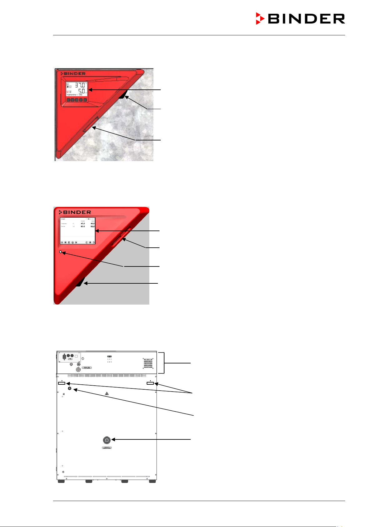
2.2 Instrument panel with regular RD4 controller
RD4 controller display
Switch for LED interior lighting (option)
USB interface
Figure 5: Instrument panel with RD4 controller and USB interface
2.3 Instrument panel with optional MB2 controller
5,7" controller display with touchscreen
USB interface
Pilot lamp
Switch for LED interior lighting (option)
Figure 6: Instrument panel with MB2 program controller and USB interface
2.4 Connections on the rear of the chamber
Rear control panel
Mounting holes for fixing the tilt protection holders
(1a) Strain relief for IEC connector plug
(12) Measuring connection with small flange DN16
Figure 7: Chamber rear (example: VD 115)
VD (E3.1) 10/2020 page 21/179
Page 22
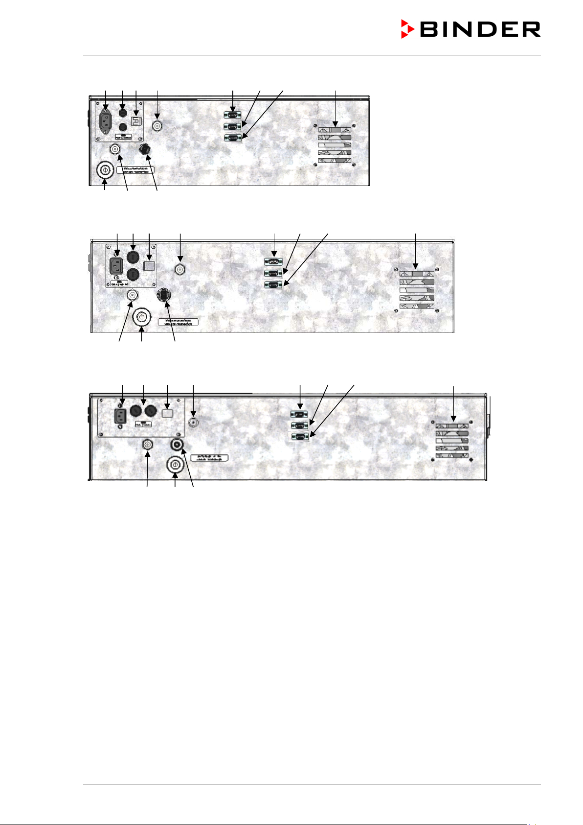
(1) (2) (3) (5) (8) (9) (10) (11)
VD 23
(6) (4) (7)
(1) (2) (3) (5) (8) (9) (10) (11)
VD 56
(4) (6) (7)
(1) (2) (3) (5) (8) (9) (10) (11)
VD 115
(4) (6) (7)
Figure 8: Rear control panel VD (230 V) with opt ions
(1) Connection for IEC connector plug 230 V AC for VD
Connection for IEC connector plug 100-120 V AC for VD -UL
(2) Miniature fuses 250 V AC (T): 2x 6,3 A for VD 23, 2x 8 A for VD 56, 2x 10 A for VD 115, 1x 10 A for
VD 23-UL, 2x 16 A for VD 56-UL, 2x 20 A for VD 115-UL
(3) Ethernet interface for computer communication
(4) Universal connection f or inert gas / ambient air “GAS/AIR” , adapter w ith hose ol ive ∅ 8 mm / 0.31
in
(5) Additional universal conne ction for inert gas / ambient air “ GAS/AIR 2” (op tion), adapter with hose
olive ∅ 8 mm / 0.31 in
(6) Vacuum connection with small flange DN16
(7) Plug “Manual ventilation” for emergency ventilation in case of power failure
(8) SUB-D socket “Pump module” for c ontro l line t o turn on/off the vacuum pum p via the sock et on th e
pump module
(9) SUB-D socket “Object temperature input” (option) for optional object temperature display
(10) SUB-D socket “Analog output” (option) for optional analog outputs for temperature and pressure
VD (E3.1) 10/2020 page 22/179
Page 23
3. Completeness of delivery, transportation, storage, and
installation
3.1 Unpacking, and checking equipment and completeness of delivery
After unpacking, p lease check the chamber and its optional acces sories, if any, based on the de livery
receipt for completenes s and for transportation dam age. Inform the carrier immediatel y if transportation
damage has occurred.
The final tests of the manufacturer may have caused traces of the shelves on the inner surfaces. This has
no impact on the function and performance of the chamber.
Please remove an y transportati on protection devices and adh esives in/o n the chamber and on th e doors
and remove the operating manuals and accessory equipment.
Due to different installat ion heights abo ve sea level, a s light negative press ure in the inner c hamber m ay
prevent the door from being opened. Therefore, af ter unpacking the cham ber, remove the plug “Manual
ventilation” (5) for emergency ventilation from the tube to ensure pressure equalization. After this,
thoroughly reinstall the plug.
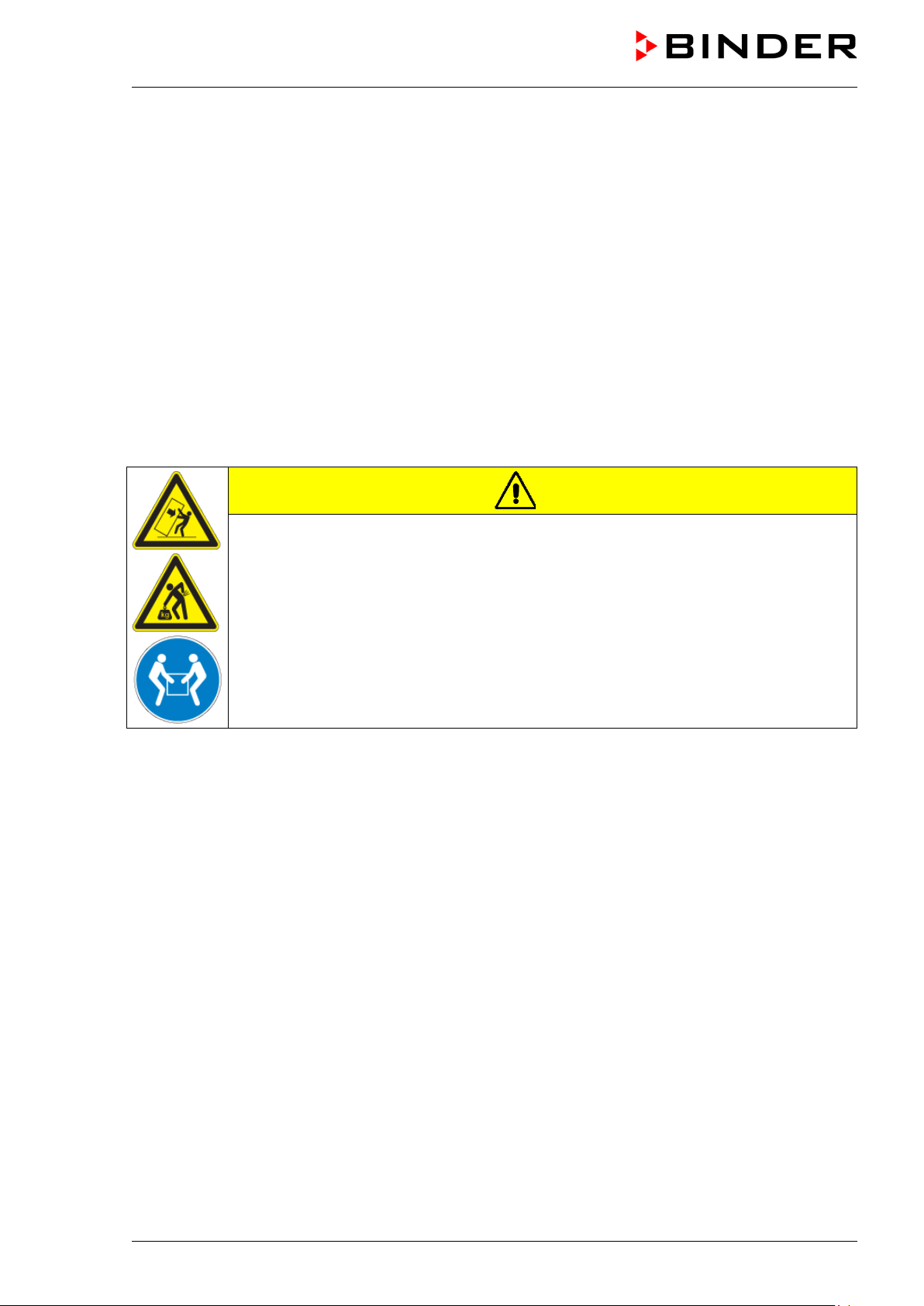
CAUTION
Risk of injury and damages by lifting heavy loads and by sliding or tilting of the
chamber due to improper lifting.
Injuries, damage to the chamber.
∅ Do NOT lift the chamber using the door handl e or the door.
Lift chambers size 23 and 56 from the pallet at the four lower corners with the aid of 4
people.
Lift chambers size 115 from the pallet with the aid of 6 people.
If you need to return the chamber, please use the original packing and obser ve the guidelines for saf e
lifting and transportation (chap. 3.2).
For disposal of the transport packing, see chap. 26.1.
If you ordered th e option al pum p module with a chem ical m embrane pum p, the pum p will be de livered in
a separate box and must be fitted into the pump module and conn ected at the place of installatio n (see
chap. 4.3.2).
Note on second-hand chambers (Ex-Demo-Units):
Second-hand chambers are chambers that wer e used for a short time for tests or exhibitions. They are
thoroughly tested before resale. BINDER ensures that the chamber is technically sound a nd will work
flawlessly.
Second-hand chambers are marked with a sticker on the chamber door. Please remove the s tic k er befor e
commissioning the chamber.
VD (E3.1) 10/2020 page 23/179
Page 24

NOTICE
3.2 Guidelines for safe lifting and transportation
After operation, please observe the guidelines for temporarily decommissioning the chamber (chap. 26.2).
CAUTION
Risk of injury and damages by lifting heavy loads and by sliding or tilting of the
chamber due to improper transportation.
Injuries, damage to the chamber.
Transport the chamber in its original packaging only.
For moving or shipping, secure the chamber with transport straps.
∅ Do NOT lift or transport the chamber using the door or handle.
Lift chambers size 23 and 56 at the four lower corners with the aid of 4 people.
Lift chambers size 115 with the aid of 6 people.
• Permissible ambient temperature range during transport: -10 °C / 14°F to +60 °C / 140°F.
You can order transport packing for moving or shipping purposes from BINDER Service.
3.3 Storage
Intermediate storage of the chamber in a closed and dry room. Observe the guidelines for temporary
decommissioning (chap. 26.2).
• Permissible ambient temperature range during storage: -10 °C / 14°F to +60 °C / 140°F.
• Permissible ambient humidity: max. 70 % r.h., non-condensing
When after storage in a cold location you transfer the chamber to its warmer installation site,
condensation ma y form. Before start-up, wait at least one hour until the cham ber has attained ambient
temperature and is completely dry.
3.4 Location of installation and ambient conditions
Set up the VD vacuum drying oven on a flat, even, and non-flammable surfac e, free from vibration, in a
well-ventilated, dry location. Align it using a spirit level. The site of installation must be capable of
supporting the chamber’s weight (see technical d ata, chap. 27.3). The cham bers are designe d for sett ing
up inside a building (indoor use).
Danger of overheating due to lack of aera tion.
Damage to the chamber.
∅ Do NOT install the chamber in unventilated recesses.
Ensure sufficient ventilation for dispersal of the heat.
Observe the prescribed minimum distances when installing the chamber.
VD (E3.1) 10/2020 page 24/179
Page 25
Do not install or operate the chamber in potentially explosive areas.
DANGER
Danger of explosion due to combustible du sts or explosive mixtures in the vicinity
of the chamber.
Serious injury or death from burns and / or explo sion pressure.
∅ Do NOT operate the chamber in potentially explosive areas.
KEEP explosive dust or air-solvent mixtures AWAY from the vicinity of the chamber.
Ambient conditions
• Permissible ambient temperature range during operation: +18 °C / 64°F to +32 °C / 90°F.
The ambient temperature should not be substantially higher than the indicated ambient
temperature of 22 °C +/- 3 °C to which the specified technical data relate. Deviations from the
indicated data are possible for other ambient conditions.
• Permissible ambient humidit y: 70 % r.h. max., non-condensing.
• Installation height: max. 2000 m / 6562 ft above sea level.
Minimum distances
• Distance between several chambers of the same size: 250 mm / 9.8 in
• Wall distances to rear: 100 mm / 3.9 in
• Lateral wall distances: 70 mm / 2.76 in
• Spacing above and behind the chamber: 100 mm / 3.9 in.
NOTICE
Danger by stacking.
Damage to the chambers.
∅ Do NOT place the chambers on top of each other.
Other requirements
To completely separat e the chamber f rom the power s upply, you m ust disconnect the power p lug. Install
the chamber in a wa y that the po wer plug is easil y access ible and can be eas ily pulled in case of danger
or to turn off the chamber.
The maximum perm issible ambient temperature of th e vacuum pumps supplied by BIND ER is 40 °C /
104 °F.
Notes when using inert gas:
When operating the VD vacuum drying oven with inert gas, correctly follow the technical ventilation
measures, as desc ribed in the DGUV guidelin es 213-850 on safe work ing in laboratories, issued by the
employers’ liability insurance association (for Germany).
For operation with inert ga s, the chamber is suppl ied with an oxygen-disp lacing gas , e.g. N
. Inert gases
2
in high concentrations are hazardous to health. They are colorless and almost odorless and theref ore
practically im perceptible. Inhalation of in ert gases can cause drowsiness up to respir atory arrest. When
content of the air decreases belo w 18%, there is risk of death from lack of oxygen. Any gas that
the O
2
might escape has to be led out via good room ventilation or a suitable exhaust system.
VD (E3.1) 10/2020 page 25/179
Page 26

The low-loss heat transfer to the material occurs via the
able in
surface contact area ensures rapid and effective heat
DANGER
Suffocation hazard due to high concentration of inert gas.
Death by suffocation.
∅ Do NOT set up chambers in non-ventilated recesses.
Make sure that technical ventilation measures are active.
Respect the relevant regulations for handling inert gases.
When decommissioning the vacuum drying oven, shut off the inert gas supply.
4. Installation and connections
4.1 Vacuum expansion racks and rack holders
Vacuum expansion racks and rack holders can easily be removed from the chamber. This offers the
advantage of an inner chamber with smooth walls, which is easy to clean.
The rack holders can only be removed from the chamber after removing the expansion racks.
Rack holder installat ion: Ali gn the rack holders to the cam s in the bot tom of the inner cham ber and insert
them.
aluminum vacuum expansion racks (also avail
stainless steel as an opt ion). The strong tension cau ses the
racks to fit tightly against the interior wall and their large-
transfer.
The removable rack holders allow for easy positio ni ng.
You can also remove the expansio n rack s for eas y cleaning.
Do not remove them too often in order to prevent wear.
Figure 9: Using the expansion racks
• Pushing the locking lever: The expansion rack is released and can be removed.
• Pulling the locking lever: The expansion rack is pressed against the inner chamber walls.
Following each new tightening of an expansion rack, check that the lateral parts of the rack fit
closely over their whole surface to the inner chamber wall. This is necessary in order to ensure
the specified temperature exactitude.
Danger of invalid calibration caused by modified thermal conductivity when
changing between aluminum and stainless-steel racks.
Undefined heating performance.
VD (E3.1) 10/2020 page 26/179
∅ Do NOT change between aluminum and stainless-steel racks.
Operate the chamber with the supplied expansion racks only.
NOTICE
Page 27
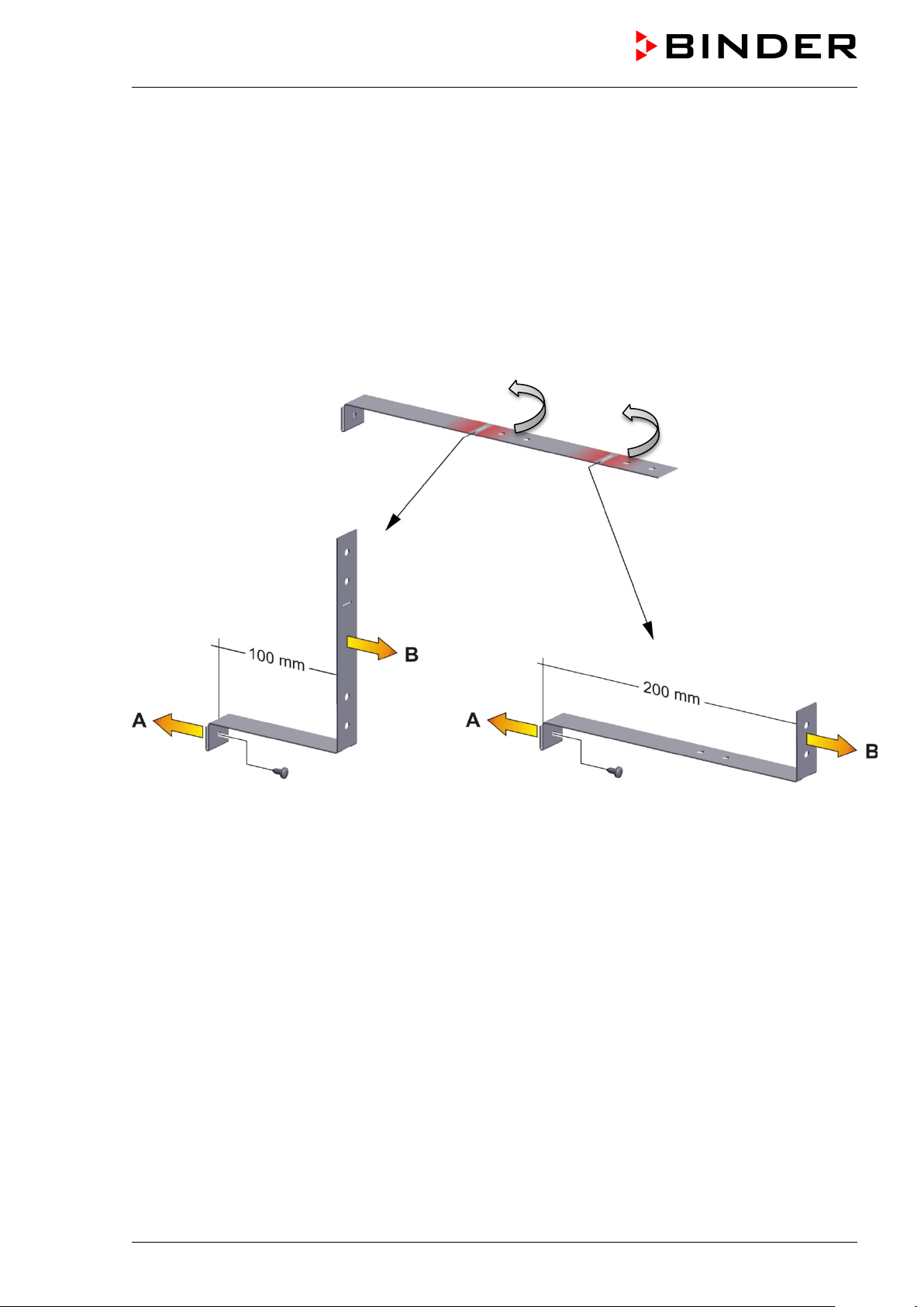
4.2 Mounting the tilt protection holders
For chambers placed on the optional pump module it is recommended to install the supplied tilt
protection.
Scope of delivery of tilt protection kit (Art.no. 8009-0870):
• 2 screws
• 2 tilt protection holders
Preparing the tilt protection holder s
• Depending on the desired wall distance, you can bend the tilt protection holders accordingly.
Figure 10: Variable length of the tilt protection holder depending on the bend
Installation on the chamber
• Plug the two t ilt protection holders each with the tab into t he mounting holes an d push them upward
over the rear panel. The screw holes in the rear wall and in the tilt protection holders must align.
• Fix the tilt protection holders each with one of the supplied screws on the chamber rear wall.
Wall mounting
• Then fix both tilt protection holders on the wall, each with 2 screws Ø 6mm suitable for the wall (B)
VD (E3.1) 10/2020 page 27/179
Page 28
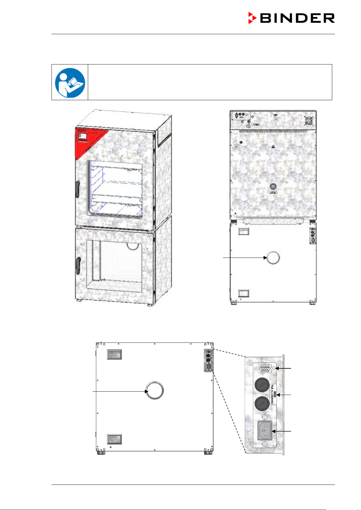
Front view
Rear view
(13)
(14)
(13)
4.3 Pump module (option)
The mounting instructions Art. no. 7001-0137 supplied with the pump module describe
how to mount the VD vacuum drying oven onto the pump module and installing the
suction line into the pump module.
Figure 11: VD mounted on pump module (example: size 115)
(15)
(16)
Figure 12: Pump module, rear view with connection panel (example: size 115)
VD (E3.1) 10/2020 page 28/179
Page 29
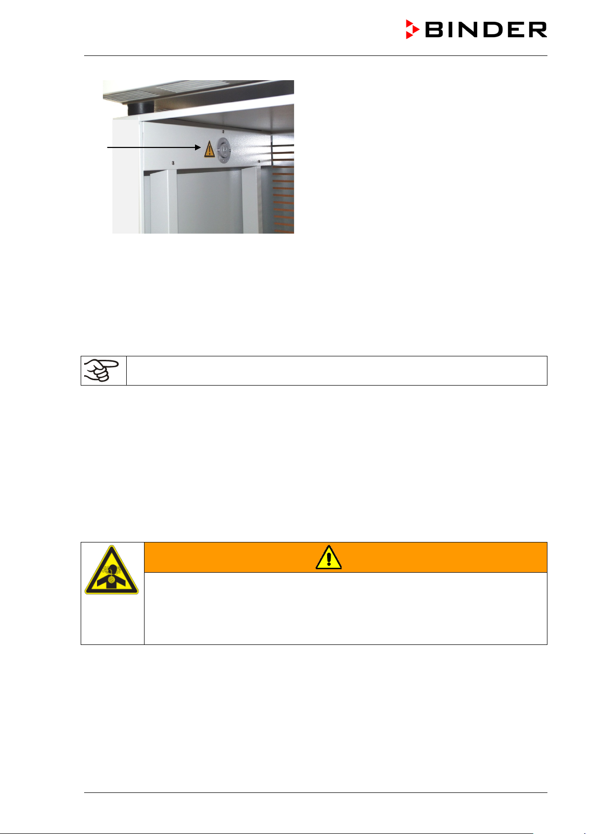
(13) Connection for extraction
(17)
(14) SUB-D socket to turn on/off the vacuum
pump
(15) Miniature fuse 8,0 A 250 V AC (T) 5x20mm
for vacuum pump 230 V or 120 V
(16) Connection socket 230 V / 16 A for IEC
connector plug 230 V AC to vacuum pump
230 V
Connection socket 125 V / 15 A for IEC
connector plug 100-120 V AC to vacuum
Figure 13: Pump module, interior view with socket for the vacuum pump
Maximum admissible load of the socket:
pump 120 V
(17) Electrical connection socket for the vacuum
pump
Standard 230 V / 50 Hz - 1 6 Am p
cUL-version 120 V / 60 Hz - 13 Am p
With CUL-version, connect only a UL listed vacuum pump with ratings of 120 V AC, 60 Hz,
and less or equal 12 Amp, 0.5 HP.
Mounting the VD on t he pump module is describe d in detail in the mounting in structions Art. No. 7001-
0137. Proceed accordingly.
4.3.1 Pump module without pump (option)
Connection to a vacuum source
Connect the vacuum connection (6) (small flange DN 16) at the rear of the chamber at the top to a
vacuum pump or to a domestic vacuum system via a vacuum hose or a fixed vacuum pipe.
When using a vacuum hos e, we recommend using the BINDER VD connection kit (Art. no. 8012-1995)
(chap. 4.4.1). The pump module has an appropriate hose outlet at the back.
4.3.2 Pump module with pump stand (option)
WARNING
Danger of health damage due to the release of ex tracted vapors.
Corrosion on the VD and pump. Damage to health.
Remove the extracted vapors from the pump module via a suitable hose into e.g., a
fume extractor facility.
Connect the hose to the vacuum pump outlet.
The VAP 1 / VAP 2 pump stand is located in a separate transport packaging. With this option, the
mounted system, consisting of VD and pump module, has a total of two power supply leads.
The connection of the control line for s witching on/off the vacu um pump via the pump module sock et is
realized as 9-poles SUB-D socket “Pump module” (8) located in the VD rear control panel.
VD (E3.1) 10/2020 page 29/179
Page 30
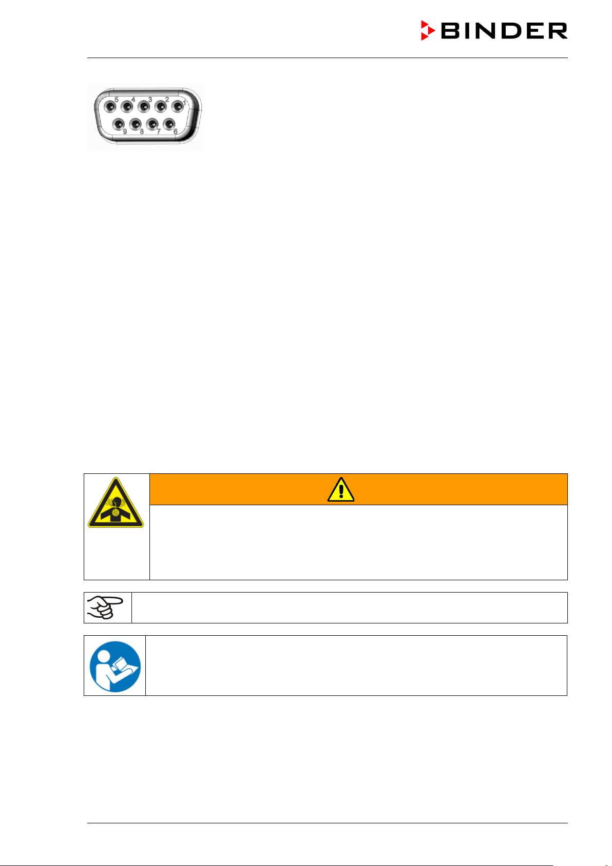
The connection is established via PIN 6 and PIN 7.
A 1.2 m cable with fitting plugs is enclosed.
Figure 14: Pin configurati on of the SUB-D socket “Pump module” ( 8) to switch on/off the pump module
socket
Installation of the supplied vacuum pump
• The vacuum dr ying oven is m ounted onto t he pum p module as desc ribed in the mounting ins tructions
Art. No. 7001-0137.
• The suction line to the pump module is installed as described in the mounting instructions Art. No.
7001-0137.
• When the pump is removed from the original packaging, place it in the pump module.
• Push the pre-installed suction line onto the opening of the vacuum pump (hose olive above the
suction-side condensate piston).
• Insert the shock proof plug of the vacuum pum p into the perm anently installed s ock et (17) in the pum p
module.
• Push a suitab le hos e f or rem oving th e ex tracted vapor s f rom the pum p module onto t he pr essur e-side
connection of the vacuum pump (hose olive at the back of the emission condenser at the top).
• Lead the hose end into an exhaust air unit.
• Connect SUB-D socket (14) at the pump module to SUB-D socket (8) in the VD rear contro l panel via
the supplied 1.2 m cable.
Extracted vapors and the inert gas use d if necessary can have a health-endan gering and / or c orrosive
effect on the chamber and the pump.
WARNING
Danger of injury by release of extracted vapors.
Corrosion on the chamber and the pump. Damag e to health.
R emove the extracted vapors from the pump module via a suitable hose into e.g., a
fume extractor facility.
Connect the hose directly to the vacuum pump outlet.
You can connect a laboratory cooling system to the emission condenser of the vacuum pumps
VAP 1 / VAP 2.
For operating the vacuum pumps VAP 1 / VAP 2, please refer to the enclosed pump
operating manual.
VD (E3.1) 10/2020 page 30/179
Page 31

Operation condition
Inlet pressure
Permitted gas temperature
Continuous operation
> 100 mbar / 2.95 inHg (high gas load)
+10 °C to +40 °C / 50°F to 104°F
Continuous operation
< 100 mbar / 2.95 inHg (low gas load)
0 °C to +60 °C / 32°F to 140°F
Short-time operation (< 5 min.)
< 100 mbar / 2.95 inHg (low gas load)
-10 °C to +80 °C / 50°F to 176°F
The VD connection kit (Art. no. 8012-1995) consists of:
BINDER vacuum pumps are designed for a gas inlet temperature of von max. 40 °C / 104°F.
Observe the permitted gas inlet temperature. The following values refer to the maximum ambient
temperature of the pump of 40 °C / 104 °F.
Do not exceed the perm itted gas inlet temper ature. An exc essive gas inlet tem perature m ay diminish the
lifetime of the pump.
NOTICE
Danger of damage to the vacuum pump by exceeding the gas inlet temperature.
Impairment of the lifespan of the vacuum pump.
∅ Do NOT exceed the set-point temperature of the permitted gas temperature.
With higher set-point temperature, take appropriate measures to cool down the sucked-
in gas before its entry to the vacuum pump
4.4 Vacuum connection
Always connect the V D vac uum drying oven to a vac u um pump or to a dom es tic vacuum system. For this
purpose, the vacuum connection (6) with small flange DN16 must be connected to the back of the
chamber at the top with th e vacuum pump or domes tic vacuum system via a vacuum suction hose. For
connecting to the chamber, BINDER recommends the connection kit VD, Art. no. 8012-1995. The
optional pump module (Chap. 4.3) has a corresponding hose outlet on its rear.
Vacuum pumps with a suction capacity of 1-30 m³/h are suitable for the VD vacuum drying
oven.
4.4.1 VD connection kit for VAP1-VAP2 (option)
• Aluminum straining ring DN10/16
• Outer centering ring DN10/16
• Small flange with hose tulles DN16/8
• 2.5 m / 98.4 in India rubber hose DN 8
• 2 hose clamps
Figure 15: VD connection kit for VAP1-VAP2
VD (E3.1) 10/2020 page 31/179
Page 32

4.5 Connecting inert gas supply
When operating the VD vacuum drying oven with inert gas, correctly follow the technical ventilation
measures, as desc ribed in the DGUV guidelin es 213-850 on safe work ing in laboratories, issued by the
employers’ liability insurance association (for Germany).
When operating with inert gas, the chamber is supplied with an oxygen displacing gas, e.g., N
gases in high concentrations are hazardous to health. They are colorless and almost odorless and
therefore practically imperceptible. Inhalation of inert gases can cause drowsiness up to respiratory
arrest. When the O
Any gas that might escape has to be led out via good room ventilation or a suitable exhaust system.
content of the air decr eases below 18% , there is risk of death from lack of oxygen.
2
. Inert
2
DANGER
Risk of suffocation by inert gas in a high concentration.
Death by suffocation.
∅ Do NOT set up chambers in non-ventilated recesses.
Ensure that technical ventilation measures are activated.
Respect the relevant regulations for handling inert gases.
When decommissioning the vacuum drying oven, turn off the inert gas supply.
Connect the inert gas supply to the universal con nection for inert gas / am bient air (adapter with hose
olive diameter 8 m m / 0.31 in) via a press ure r educ er. Sc rew t he enc losed adapte r with hos e ol ive on t he
thread (4) at the cham ber rear. Set the press ure reducer to a press ure slightly above am bient pressure.
Ensure that the pressur e re duc er will cert a inl y ope n. Do not alter this setting in or der to a vo id pert ur bat io n
inside the oven and release of big quantities of inert gas after flooding the VD.
NOTICE
Danger of perturbations by overpressure in the inner chamber.
Perturbation of the load.
∅ DO NOT change the setting of the atmospheric pressure.
VD (E3.1) 10/2020 page 32/179
Page 33

4.6 Electri cal co nn ect io n
The chambers are supplied ready for connection. They come with an IEC connector plug.
Model
VD 23
VD 56
VD 115
VD 23-UL
VD 56-UL
VD 115-UL
• The domes tic socket must also provide a protec tive conductor. Make s ure that the connection of th e
protective conductor of the domestic installations to the chamber’s protective conductor meets the
latest technology. The protective conductors of the socket and plug must be compatible!
Power plug of the
power cable
IEC connector plug
(grounded)
IEC connector plug
(grounded)
IEC connector plug
(grounded)
NEMA 5-15P 100-120 V at 60 Hz 1N~ 10 A
NEMA 5-20P 100-120 V at 60 Hz 1N~ 2 x 16 A
NEMA 5-20P 100-120 V at 60 Hz 1N~ 2 x 20 A
Nominal voltage ± 10% at the
indicated power frequency
230 V at 50 Hz
230 V at 60 Hz
230 V at 50 Hz
230 V at 60 Hz
230 V at 50 Hz
230 V at 60 Hz
Current
type
1N~ 2 x 6,3 A
1N~ 2 x 8 A
1N~ 2 x 10 A
Chamber
fuse
DANGER
Electrical hazard due to missing protecti ve conductor connection.
Deadly electric shock.
Make sure that the chamber’s power plug and the power socket match and
securely connect the electrical protective conductors of the chamber and the house
installation.
• Prior to con nect ion and s tar t-up, chec k the po wer su ppl y voltag e. Com par e the v alues to the s pecif ied
data located on the chamber’s type plate (chamber front behind the do or, bottom left-hand, see cha p.
1.6).
NOTICE
Danger of incorrect power supply voltage due to improper connection.
Damage to the chamber.
Check the power supply voltage before connection and start-up.
Compare the power supply voltage with the data indicated on the type plate.
• When connecting, please observe the regulations specified by the local electricity supply company and
as well as the VDE directives (for Germany). We recommend the use of a residual current circuit
breaker.
• After connecting the po wer c able to connection (1), lead it through the strain relief (1a).
• Only use original connection cables from BINDER according to the above specification
• Pollution degree (acc. to IEC 61010-1): 2
• Over-voltage category (acc. to IEC 61010-1): II
See also electrical data (chap. 27.3).
To completely separate the chamber from the power supply, you must disconnect the power
plug. Install the chamber in a way that the power plug is easily accessible and can be easily
pulled in case of danger or to turn off the chamber.
VD (E3.1) 10/2020 page 33/179
Page 34

Status icons
T / pressure (mbar)
Icon
Signification
Icon
Signification
Icon
Signification
Function
5. Functional overview and menu structure of the controller
The available control ler functions depend on t he current aut horization (cha p. 9). U nless noted ot herwise,
the figure in this manual show the functional range, which is available for the user with “Admin”
authorization level
5.1 RD4 controller
The RD4 chamber controller controls following parameters inside the chamber:
• Temperature in °C or °F
• Pressure in mbar
You can enter the desired set p oint values in the “ Set points” menu directly at t he controller or use the
APT-COM™ 4 Multi Management Software (option) specially developed by BINDER.
The controller offers various notifications and alarm messages with visual and audible indication. All
controller settings remain valid until the next m anual change. They are stored also af ter turning off the
chamber.
Temperature values
Pressure values
Text information
Figure 16: Normal display of the RD4 controller (sample values)
Depending on the configuration, pressure values are shown in mbar or psi.
Status icons in the controller display
Heating active
Display of activated special controller functions:
1 = Standby mode
Information
2 = Optional universal connection for inert gas /
ambient air “GAS/ AIR 2” (5) activated
3 = All valves closed
Collective alarm
4 = Vacuum pump switched off
Functional controller keys
Arrow-up button
Arrow-down
button
VD (E3.1) 10/2020 page 34/179
• Navigate between menus, submenus, other functions
• In the setting menu: change setting, decrease value
• Navigate between menus, submenus, other functions
• In the setting menu: change setting, increase value
Page 35

Icon
Signification
Function
Turning on / off pressure control and temperature
Turning on / off the vacuum pump and the optional
Configuration display (setup information, controller
Display of interface configuration (e.g. MAC address,
Setting the tolerance rang er limits and delay times for
• Select menu, submenu, function
• In the setting menu: Confirm entry
OK button
• Back to previous menu level.
Back button
• Press down 5 seconds to simultaneously display the inner chamber
temperature and the heating element temperature (chap. 10.1.8)
Standby button Turning on 7 off the chamber (chap. 6.2)
5.1.1 Menu structure of the controller and access levels
Starting from Norm al display, na vigate bet ween the menus with the a rrow buttons. W ith the OK button
you enter the setting of f urther subordinate menu functions. W ith the Back button you go back to the
previous function and finally back to Normal display.
Starting from Normal display you can directly access the quick access menu functions with the OK
button.
The available functi ons dep end on the c ur rent dependent on the curre nt authorization “User”, “Admin” or
“Service”, for which the entry of a password may be required, depending on the setting.
You can set passwords for different access levels:
• User: The password enab les access to the s tandard operating f unctions. Factory setti ng is 00 00 (no
password assigned).
• Admin: The password enables access to advanced controller functions and settings. Factory setting is
00 01.
• Service: The password enables access to all controller functions (for BINDER Service only).
As soon as a password has been assigned, access to the respective functions is blocked and only
available after entering the correct password.
Menu Required access level Functions
Quick access Any user
•
control
• Starting / stopping D rying monitoring
Setpoints “User”
• Temperatur e and press ur e set -point setting
• Setting the safety controller
•
connection “GAS/ AIR 2” (5)
• Closing all fine dosing valves
Programs “User”
Chamber info Any user
• Start / Stop function for time and week program
•
hardware and software, analog inputs)
•
IP address)
Settings “Admin”
VD (E3.1) 10/2020 page 35/179
• General contr oller settings (date, time, menu lang uag e ,
temperature unit, display brightness…)
• Network settings
• Setting the data logger storage interval
•
tolerance range alarms
• Password changing for User and Admin
Page 36

Operating mode
Menu Required access level Functions
Service “Service”
• Configuration settings (only for BINDER Service)
• Password changing for User and Admin
USB Export: Any user
Import: “Admin”
• Export of configuration, logger, and service data
• Import of configuration data
Unless noted otherwis e, the figure in this m anual show the functional range, which is a vailable for the
user with “Admin” authorization level
Note: When specifying the path to the respective function, the possibly required entry of a password is not
listed.
5.2 MB2 controller
The MB2 chamber controller controls following parameters inside the chamber:
• Temperature in °C or °F
• Pressure in mbar
You can enter the desired set point values in fixed valu e oper at io n mode directly on the display surf ac e or
via the setpoint menu. F or program operatio n the cont roller off ers programm ing week and tim e progr ams .
In addition, there is a timer program available (stopwatch function).
The controller offers various notifications and alarm messages with visual and audible indication and
remote alarms via e-mail, an event list (trac e f i le) a nd the graphical displa y of the measuring values in the
chart recorder view. T he MB2 pr ogram controller per mits program m ing temperatu re and pres sure c ycles,
and specifying spec ial controller functions for e ach program section. You can enter values or programs
directly at the controller or use the APT-COM™ 4 Multi Management Software (option) specially
developed by BINDER.
Figure 17: Normal display of the MB2 program controller (sample values)
Temperature values
Pressure values
Actual values
Set-point values
Functional icons
VD (E3.1) 10/2020 page 36/179
Page 37

Current operating mode
Date, time, authorization level of
5.2.1 Operating functions in normal display
Text list for information icons
the logged-in user, memory
Quick setpoint entry
Continue to next screen
Back to Normal display
Information
Program start
Setpoint entry
Event list
Display of active alarms
Access to main menu
Figure 18: Operating functions of the MB2 controller in normal display (example values)
VD (E3.1) 10/2020 page 37/179
Page 38

5.2.2 Display views: Normal display, program display, chart-recorder display
Press the Change view icon to toggle between normal display, program display and chartrecorder display.
Press the Normal display icon to return from program display and chart recorder display back to
Normal display.
Normal display (actual values / setpoint values)
Program display (example: time program)
Chart recorder display
VD (E3.1) 10/2020 page 38/179
Page 39

Icon
Signification
Function
Icon
Signification
Function
5.2.3 MB2 controller icons overview
Navigation icons in Normal display
Main menu Access from Normal display to the main menu
Alarm Access from Normal display to the list of active alarms
Event list Access from Normal display to the event list
Access from Normal display to the setpoint entry menu: setpoint
Setpoint setting
entry for Fixed value operation, turning on/off temperature and/or
pressure control, safety controller settings
Program start
Program pause Pause a running time program
Program cancelling Cancel a running time or week program
Information
Normal display
Change view
Functional icons in individual menus
Back Return from each menu to Normal display
Update Update the event list and alarm messages
Confirm
Start a previously entered time or week program,
continue a paused time program
Information on program operation, setpoints, actual values, and
the safety controller
Return from program display or chart recorder display to Normal
display
Toggle between Normal display, program display, and chart
recorder display
Take over the entries and exit the menu / continue menu
sequence.
Exit the menu / cancel menu sequence. Entries are not taken
Close
over. When terminating a menu sequence, an information
window appears, which must be confirmed.
Reset alarm Acknowledge the alarm and mute the buzzer.
Change keyboard
Change between uppercase and lowercase characters, digits
and special characters
Edit Edit settings of time and week programs
VD (E3.1) 10/2020 page 39/179
Page 40

Icon
Signification
Function
Icon
Text information
Condition
Icon
Information
Functional icons in the chart recorder display
Show legend Show legend
Hide legend Hide legend
History display
Pause chart recorder and change to history display. Data recording
continues.
Curve selection Go to “Curve selection” submenu in the history display
Go to “Search” submenu in the history display to select the required
instant
Search
Zoom Go to “Zoom” submenu in the history display to select the zoom factor
Show scroll buttons Show scroll buttons in the history display to scroll to an instant
Hide scroll buttons Hide scroll buttons in the history display to scroll to an instant
Information icons referring to chamber conditions
“Standby” Chamber is in Standby mode
“Heating active” Chamber is heating up
“All valves are closed” All valves are closed
“GAS/AIR” Ventilation via regular connection “GAS/AIR” (4)
“GAS/AIR 2”
“Vacuum pump off” Vacuum pump turned off
Information icon for data processing
Waiting icon: Data processing is running.
Remaining time to touch the display when calibrating the touchscreen.
Ventilation via optional connection “GAS/AIR2” (5)
Regular connection “GAS/AIR” (4) deactivated.
VD (E3.1) 10/2020 page 40/179
Page 41

5.2.4 MB2 controller operating modes
The MB2 program controller operates in the following operating modes:
• Fixed value operating mode
The controller operates as a fixed-point controller, i.e., set-poi nts f or tem peratur e and press ure can b e
defined, which are then maintained until the next manual change (chap. 7.2.1).
• Timer program operation
Stopwatch function: during an entered duratio n the controller constantl y equilibrates to the setpoints
entered in Fixed value operation mode.
• Time program operation
An entered time program for temperature and pressure is running. T he controller offers 25 program
memory places with 100 pr ogr am sections each. The total num ber of pr ogram sections of all programs
is unlimited
• Week program operation
An entered week pr ogram for temperature and press ure is running. The control ler offers 5 program
memory places with 100 switching points each. The switching points can be distributed over all days of
the week.
5.2.5 MB2 controller menu structure
Main menu: program settings, further information, “Service” submenu.
The “Settings” submenu allows general configuration of the controller.
List of active alarms chap. 13.2
Access to the event list
Use the navigation icons in the screen footer in
Normal display to access the desired controller
functions.
The available functions depend on the current
authorization level “Service”, “Admin” or “User”
(chap. 9.2.1). This is selected either during login or
can be available without password protection.
chap.
5.2.5.1
chap.
10.2.5
Setpoint entry for Fixed value operation, Standby mode, turning on/off
temperature and/or pressure control, safety controller settings
Start/ pause/ cancel an already entered, respectively a running time
program or start / cancel an already entered, respectively a running
week program
Unless noted otherwise, the figures show the functional range, which is available for the user with
“Admin” authorization level.
VD (E3.1) 10/2020 page 41/179
chap. 7.2.1,
8.6.2,
11.2.2.3
chap. 16.1,
16.2, 17.1
Page 42

Program start/stop submenu for time and
“User” authorization level)
5.2.5.1 Main menu
The main menu provides a ccess to the general conf iguration of the contro ller as well as to program entry
and the user administrat ion. Additionally, there ar e support functions like a contact pag e or the display
calibration depending on the available angle.
Press the Main menu icon to access the main menu from Normal Display.
Press the Back icon to return from each setting menu to Normal Display.
The main menu provides the following functions and submenus.
User management: login and logout,
password management
Chamber information chap. 10.2.7
“Settings” submenu (not visible for user with
“User” authorization level)
week programs (not visible for user with
“Service” submenu chap. 5.2.5.3
BINDER Service contact page chap. 10.2.6
Calibrating the touch screen chap. 10.2.4.2
Back to Normal Display
“Settings” submenu
• Settings of many general controller functions and network settings (chap. 10).
chap. 9.2.1
chap. 10
chap. 16 and 17
• Available only for users with “Service” and “Admin” authorization level
“Service” submenu
• Access to service data, controller reset to factory settings (chap. 5.2.5.3)
• Available on ly for users with “Service” and “A dmin” authorization level. Full f unctional range only for
BINDER Service (users with “Service” authorization level).
“Programs” submenu
• Access to the controller’s program functions (chap. 15, 16, 17)
• Available only for users with “Service” and “Admin” authorization level
VD (E3.1) 10/2020 page 42/179
Page 43

Setting the temperature unit, menu
language…
chap. 10.1.1,
10.2.2
Setting the display brightness, continuous
operation and screen saver
Settings for the measurement chart: storage
maximum values
tolerance range alarm
(not used)
Configuration of the e-mail server, assignment
of e-mail addresses
of the controller software
5.2.5.2 “Settings” submenu
The “Settings” s ubmenu is available for us ers with “Service” or “Adm in” authorization level. It serves t o
enter date and tim e, select the l anguag e for the contro ller m enus and the des ired t em peratur e unit and to
configure the controller’s communication functions.
Path: Main menu > Settings
Setting date and time chap. 10.2.2
chap. 10.2.4
interval, storage values, minimum and
Setting the tolerance range and delay time for
Entry of the MAC address and IP address chap. 18.2.1
Password protection for web server access chap. 18.2.2
Back to main menu
chap. 21.2
chap. 12
chap. 18.2.3
5.2.5.3 “Service” submenu
The “Service” submenu is available for us ers with “Service” or “Admin” authori zation level. W hen loggedin with “Admin” authorization level the user will find information to tell the BINDER Service in service
case.
Path: Main menu > Service
(view with “Admin” authorization level)
VD (E3.1) 10/2020 page 43/179
Serial number of the chamber, setup version
No function
Information for BINDER Service
Reset to factory settings
Back to main menu
chap. 10.2.2
Page 44

5.2.6 Principle of controller entries
In the selection and entr y menus there ar e icons displa yed in the footers which you ca n use to take over
the entry or cancel it.
Selection menu (example)
After completing the settings there are the following possibilities:
Press the Confirm icon to take over the entries and exit the menu or continue the menu
sequence.
Press the Close icon to exit the menu or cancel the menu sequence without taking over the
entries.
When terminating a menu sequence, an information window appears, which must be confirmed.
Entry menu (example)
5.3 Performance during and after power failures
During a power failure, all controller functions are shut down.
If there is a vacuum and venti lation is require d during t he durat ion of the power f ailure, th is is pos sib le via
the emergency ventilatio n (chap. 6.4.3).
After the power returns, all functions return to the same status the chamber had before power failure.
All settings and set point values remain in the memory during power failure.
• If the Standby m ode had been activated prior to the p ower failure, the chamber rem ains off after the
power returns. To operate it you must sign in with a higher authorization level and deactivate the
standby mode.
• If the Standby mode had been deactivated prior to the power failure, operation continues after the
power returns with previously entered parameters.
5.3.1 RD4 controller
After the power returns, the set-points are immediately resumed.
If during power failure an al arm has occur red (e.g., tolerance range, safet y controller), conf irm the alarm .
See chap. 13.3.
VD (E3.1) 10/2020 page 44/179
Page 45

5.3.2 MB2 controller
After the power returns, the controller continues to function in the original operating mode it was in
previously before the power failure occurred:
• Performance after power failure in Fixed value operation mode
All functions return to the same status the chamber had before power failure. The set-points are
immediately resumed.
• Performance after power failure during Timer operation
The set-points which had been active at the moment of program start are resumed. Program run
continues.
• Performance after power failure during Time program operation
The program is res umed at the point where t he int err u ptio n oc c urr ed with the l ate s t s et -poi nts reac h ed
during the program run.
• Performance after power failure during Week program operation
The week program continues with the values corresponding to the current time.
Power failure and power return are noted in the Event list (chap. 10.2.5).
If during power failure an alarm has occurr ed (e.g., to lerance rang e, safet y controller) , confirm the alarm .
See chap. 13.3.
6. Start up
With regard to operati ng the vacuum drying oven VD and the vacuum pump, please observe t he DGUV
guidelines 213-850 on safe working in laboratories, issued by the employers’ liability insurance
association (for Germany).
Note: Warming chambers may release odors in the first few days after commissioning. This is not a
quality defect. To reduce odors quickly we recommend heating up the chamber to its nominal
temperature for one day and in a well-ventilat ed locat io n.
6.1 Condition after establishing the power connection
Prior to establishing the power connection, the following points must certainly be met:
• Installation of the chamber (chap. 4) performed in compliance with the installation guidelines and
ambient conditions (cap. 3.4)
• Vacuum supply connected (chap. 4.3)
• If required: Inert gas connection establis he d (chap. 4.5)
Establish the power connection: connect the power plug (chap. 4.6). Connect the power supply only when
needed, and disconnect it when the chamber is not in use for an extended period.
MB2 controller: After es tablishing power supp ly the pilot lamp in the ins trument panel shows re adiness
for operation.
The authorization leve l is “User”. T o be able to use the ent ire functional ity of the contr oller (e.g., Settings
menu functions, program functions, activating / deactivating Standby mode), log in with the desired
authorization level.
All parameters, set-points and settings remain the same as before turning off.
• If the Standby m ode had been activated prior to the p ower failure, the chamber rem ains off after the
power returns. To operate it you must sign in with a higher authorization level and deactivate the
standby mode.
• If the Standby mode had been deactivated prior to the power failure, operation continues after the
power returns with previously entered parameters.
VD (E3.1) 10/2020 page 45/179
Page 46

Standby
Standby
6.2 Standby mode: Turning on and off the vacuum drying oven
Activate the chamber only as required. Switch the chamber to standby mode when it is not in use.
All settings and setpoint values are saved after turning off the chamber.
If a program is running, it will be canceled by activating the standby mode
In Standby mode, the heating and the fan on the c hamber rear are off, all val ves are closed, and the
socket for the pump in the pump module is de-energized. Heating control and pressure control are off.
To completely separate the chamber from the power supply, you must disconnect the power plug.
For decommissioning observe the guidelines in chap. 26.2.
6.2.1 RD4 controller
Activating / deactivating Standby mode via controller keyboard:
Deactivating Standby mode (turning on the chamber):
After establishing power supply, press down the Standby button for 5 seconds to turn on the chamber.
The controller shows normal display and controls temperature and pressure to the last entered values.
Activating Standby mode (turning off the chamber):
To turn off the chamber press down the Standby button for another 5 seconds.
Activating / deactivating Standby mode via controller menu:
Required access level: “User”.
Path: Normal display Setpoints Functions on/off Standby
Press the OK button to access the function “Standby”.
Function 1 “Standby”.
The current switching state is shown (example).
Press the OK button to enable the setting.
Setting the function 1 “Standby”.
The current setting flashes. Use the arrow buttons to select between
“0” (Standby mode deactivated) and “1” (Standby mode activated).
Confirm the setting with the OK button.
With the Back button you can go back to the “Functions on/off” submenu and, repeatedly pres sing it, to
Normal display.
With setting “1” (Standby mode), the icon is shown in Normal display.
When the controller display is dark in standby mode, press any button to activate it for 10 seconds.
VD (E3.1) 10/2020 page 46/179
Page 47

6.2.2 MB2 controller
Required authorization: “Admin”.
Press the Setpoint setting icon to access the “Setpoint” setting menu from Normal display..
Path: Setpoint > Fixed value operation setpoints > Functions on/off
In this menu you can activate and deactivate the Standby mode .
Activating the Standby mode (turning off the chamber):
“Functions on/off” menu
Mark the checkbox of the function “Standby” to activate
it and press the Confirm icon.
In the “Setpoints” menu press again the Confirm icon.
The controller changes to Normal display.
When the function “Standby” is activated, the “Standby” icon is displayed in the screen header in
Normal display. Press the flash icon next to the information icon to display the corresponding text
information “Standby” (information messages, chap. 13.1.2).
When the controller display is dark in standby mode, press on the touchscreen to activate it for 10
seconds.
Deactivating the Standby mode (turning on the chamber
To deactivate the “Standby” function, unmark the checkbox.
VD (E3.1) 10/2020 page 47/179
Page 48

6.3 Controller settings upon start up
Depending on the functions activated in the controller, various settings can be requested directly after
turning on the chamber.
Then you should assign a password for the operating level (chap. 9).
6.3.1 RD4 controller
If the function “Lang uage selection at r estart” has been acti vated (chap. 10.1.5, fact ory setting ON), the
following settings are checked upon start up:
• Menu language (chap. 10.1.1):
Use the arrow buttons to select the desired language, confirm with the OK button
• Temperature unit (chap. 10.1.2):
Use the arrow buttons to select the desired temperature unit, confirm with the OK button
• Current date (chap. 10.1.3), format DD MM YYYY:
Use the arrow buttons to set the day, continue with the OK button.
Use the arrow buttons to set the month, continue with the OK button.
Use the arrow buttons to set the year, confirm with the OK button
• Current time (chap. 10.1.4), format HH:MM:
Use the arrow buttons to set the hours, continue with the OK button.
Use the arrow buttons to set the minutes, confirm with the OK button
6.3.2 MB2 controller
The window “Language selection” enables the language selection, in case that it’s activated in the
“Start-up” menu. Afterwards occurs a request of the time zone and the temperature unit.
The controller wi ll f unc tio n i n th e ope rating mode, which was active bef ore the last shut-down. It contr ols
temperature and pressure in fixed value operating mode to th e last entered values a nd in the program
mode to the set points achieved beforehand.
VD (E3.1) 10/2020 page 48/179
Page 49

Locked operation
Provided that the user administr atio n has bee n activat ed by the as signm ent of pas swords for the diff erent
authorization types, the controller operation is first l ocked after tur ning on the unit, recogn izable by the
closed lock icon in the header.
In the locked view the controller provides all display functions. No setting functions are available.
The setpoints are sh aded (light gre y) in normal disp lay. Changing them by direct entr y in the fixed va lue
operating mode is not possible. T he function al icons f or setpoint en try and pr ogram start in the foot er are
without function.
After turning on the unit, user log-in is required to operate the controller (chap. 9.2.2)
Operation without user log-in / without password-protection
If the password functi on ha s been deac t ivated, after turning on the uni t without user log-in ther e are t h ose
controller functions available, which correspond to the highest authorization level without a password
protection. There is no lock icon in the header.
6.4 Vacuum system
With regard to operat ion, please obser ve the DGUV guidel ines 213-850 on saf e working in laborat ories,
issued by the employers’ liability insurance association (for Germany).
Starting situation: The vacuum source is connected and ready for operation.
For the pump module with chemical membrane pump option, see chap. 4.3.2.
6.4.1 Evacuation
Preparation:
• Make sure that the “Manual ventilation” plug (7) for emergency ventilation i n case of a power failure,
which is located on the chamber rear, is closed
• Pressure control must be activated.
• Turn on the vacuum pump. The pump shall continue running during the entire drying procedure.
• Set the desired pressure set-point on the controller (chap. 7).
• Monitor the internal pressure on the controller display
As long as there is a vacuum, never try to open the oven by force.
VD (E3.1) 10/2020 page 49/179
Page 50

6.4.2 Ventilation after completing the drying procedure (flooding with ambient air or
inert gas)
The duration of th e dr ying procedur e can be determ ined vi a the pres sure dis pla y on the con troller. W hen
the decreasing pressure reaches the set-point value, the drying process is completed. If the drying
monitoring (section 8.7) is activated, a corresponding message is displayed.
To break the vacuum (ventilation) after completing th e drying procedure, set the des ired pressure setpoint to atmospherical pressure (chap. 7). The ven tilation valve opens, and ambient air or iner t gas flow
into the inner chamber.
Regularly the inert gas connection / ambient air inlet “GAS/AIR” (4) is used for ventilation
Chambers can be equipped as an option with an additional inert gas connection / ambient air inlet
“GAS/AIR2” (5), which can be used a ltern ativel y. To do this, the controller func tio n “GAS/AIR 2” serves to
close the valve of the standard connection “GAS/AIR” (4). Then the valve of the optional connection
“GAS/AIR 2” (5) is used for ventilation (chap. 8.3). This allows convenient switching when both
connections are used differently (e.g., for inert gas and ambient air).
Ambient air is sucked in through t he inert gas connec tion / am bient air inlet (4) or (5). The ambient air is
introduced into the lo wer part of the rear pa nel of the inner cham ber and is evenl y distribut ed in the inner
chamber. This supply of ambient air by under-flooding prevents turbulence of pulverized drying material.
6.4.3 Ventilation / breaking the vacuum in case of a power failure
To be able to open the ch amber in case of a power failure, r emove the “Manual ventilation” plug (7) for
emergency ventilation, which is located on the chamber rear.
As long as there is a vacuum, never try to open the oven by force.
Make sure that the drying procedure is complete before breaking the vacuum. Otherwise, you
should wait for the power to return to continue the drying procedure
6.4.4 Operation wit h inert gas
When operating the VD vacuum drying oven with inert gas, correctly follow the technical ventilation
measures, as desc ribed in the DGUV guidelin es 213-850 on safe work ing in laboratories, issued by the
employers’ liability insurance association (for Germany).
Inert gases in high concentrations are hazardous to h ealth. They are co lorless and alm ost odorless and
therefore practically imperceptible. Inhalation of inert gases can cause drowsiness up to respiratory
arrest. When the O
Any gas that might escape has to be led out via good room ventilation or a suitable exhaust system.
content of the air decr eases below 18%, t here is risk of death f rom lack of ox ygen.
2
DANGER
Danger of suffocation by high concentration of inert gas.
Death by suffocation.
∅ Do NOT set up chambers in non-ventilated recesses.
Ensure technical ventilation measures.
Respect the relevant regulations for handling these gases.
When decommissioning the vacuum drying oven, turn off the inert gas supply.
VD (E3.1) 10/2020 page 50/179
Page 51

Temperature
Install a pressure reduc er for inert gas operation. Set the pr essure reducer to a pressur e slightly above
ambient pressure. Ens ure that the pressure reducer w i ll open. Do not change this setting in or der to a vo id
perturbation inside the oven and release of big quantities of inert gas after flooding the VD.
For ventilation an inert gas, e.g., nitrogen, is led into the inner chamber via the connection (4) or the
optional connection (5), until pressure compensation with the atmosphere occurs. Depending on the
individual application, you can perform a second evacuation and repeat the inert gas flooding.
When the inert gas f ine dosing valve is open, a maxim um of approx. 0.6 m³/h gas flows into the inner
chamber. The introd uction of inert gas by under-f looding in the lower region of the inner chamber rear
wall and the extraction at the inner chamber ceiling allow an effective inert gas flushing.
If the oven is charged to full capacity, depending on the load, deviations from the specified
heating up times may occur.
7. Set-point entry
Setting ranges Control ranges
Temperature
0.0 °C / 32 °F up to 220.0 °C / 428 °F
10 °C / 18 °F above ambient temperature up to
220 ºC / 428 °F
Pressure 0 mbar up to 1100 mbar 0 mbar up to 1100 mbar
7.1 RD4 controller
7.1.1 Temperature set-point entry
Required access level: “User”.
Path: Normal display Setpoints Temperature
Press the OK button to enable the setting.
With the arrow-down button you can continue with the pressure set-point entry (chap. 7.1.2).
With the Back button you can go back to the “Setpoints” submenu and, repeatedly pressing it, to
Normal display.
Temperature setting.
The current setting flashes. Enter the desired set-point wit h the arrow
buttons.
Confirm the entry with the OK button.
With safety controller mode “Limit”, adapt the safety controller always when you changed the
temperature set-point. Set the safety controller value by approx. 5 °C above the temperature
set-point (chap. 11.2.2).
Recommended setting: safety controller mode “Offset” with safety controller value 5 °C.
VD (E3.1) 10/2020 page 51/179
Page 52

Pressure (mbar)
7.1.2 Pressure set-point entry
Required access level: “User”.
Path: Normal display Setpoints Pressure
Press the OK button to enable the setting.
Pressure setting
The current setting flashes. Enter the desired set-point wit h the arrow
buttons.
Confirm the entry with the OK button.
With the arrow-up button you can go back to the temperature set-point entry (chap. 7.1.1).
With the arrow-down button you can now change to the special controller functions setting (chap. 8).
With the Back button you can go back to the “Setpoints” submenu and, repeatedly pressing it, to
Normal display.
7.2 MB2 controller
In Fixed value operating mode, you can enter a temperature set-point, a pressure set-point, and the
switching-state of special controller functions.
All settings made in Fixed value operating mode remain valid until the next manual change. They are
saved also when turning off the chamber or in case of toggling to Program Mode.
The values entered in Fixed value mode become valid again after the end of a program and
will then be targeted and equilibrated.
When operating without a vacuum by setting “Pressure control off” (chap. 8.6.2), the pressure
tolerance range function is automatically deactivated.
7.2.1 Set-point entry through the “Setpoints” menu
Press the Setpoint setting icon to access the “Setpoint” setting menu from Normal display.
VD (E3.1) 10/2020 page 52/179
Page 53

“Setpoints” menu.
Select “Fixed value operation setpoints” to access the
individual parameters.
• Select the field “Temperature” and enter the desired temperature setpoint.
Confirm entry with Confirm icon.
• Select the field “Pressure” and enter the desired pressure setpoint.
Confirm entry with Confirm icon.
When entering a value outside the setting range, the message: “Value outside of limits! (Min:
xxx, Max: xxx)” appears (xxx is a wildcard for the limits of the respective parameter). Press the
Confirm icon and repeat the entry with a correct value.
After completing t he s ett ing s , pres s th e Confirm icon to take over th e entr i es and exit the m enu, or press
the Close icon to exit the menu without taking over the entries.
With set-point type “Limit”, adapt the safety controller (chap. 11.2) always when you changed
the temperature set-point. Set the safety controller set-point by approx. 5 °C above the
controller temperature set-point.
Recommended setting: Set-point type “Offset” with safety controller set-point 5 °C.
7.2.2 Direct setpoint entry via Normal display
Alternatively you can also enter the setpoints directly via Normal display.
Normal display. Select the setpoint you want
to change.
VD (E3.1) 10/2020 page 53/179
Example: “Temperature” entry menu. Enter the
desired setpoint and confirm entry with Confirm
icon.
Page 54

Functions 1, 2,
Functions on/off
8. Setting special controller functions
You can set the following functions via the controller menu:
• Activate / deactivate the Standby mode (chap. 6.2)
• Turning off the vacuum pump via the socket on the pump module (chap. 8.2)
• Use the optional connection “GAS/AIR2” (5) for ventilation (chap. 8.3)
• Close all existing fine dosing valves (chap. 8.4)
• Turning on / off temperature control (chap. 8.5)
• Turning on / off pressure control (chap. 8.6)
• Starting / terminating the drying monitoring (chap. 8.7)
8.1 Menu structure
8.1.1 RD4 controller
Required access level: “User”.
8.1.1.1 “Functions on/off” menu
In the “Functions on/off” menu you can define the switching state of three special controller functions.
Path: Normal display Setpoints Functions on/off
The functions are displayed from left to right.
Example: Function 1 activated = 1000. Function 1 deactivated = 0000.
Press the OK button to access the first individual function. With the arrow-down button you can
proceed to the subsequent functions.
• Function 1 “Standby” (chap. 6.2)
• Function 2 “GA S/AIR 2” (chap. 8.3)
Submenu “Functions on/off”.
This view shows the switching states four functions.
and 3 are available with the present chamber type.
“1” = Function activated
“0” = Function deactivated
• Function 3 “Close all valves” (chap. 8.4)
• Function 4 “Vacuum pump off” (chap. 8.2)
Press the OK button to enable the sett in g of the desired function and select th e f unc tio n’s switching state
“1” (function activated) or “0” (function deactivated).
With the Back button you can go back to the “Setpoints” submenu and, repeatedly pressing it, to
Normal display.
In Normal display the acti vated functions are indica ted by an icon showing th e number of the respec tive
function. If several functions are simultaneously active, the icon displays a combination of the
corresponding number s , e.g.
VD (E3.1) 10/2020 page 54/179
Page 55

T / pressure (mbar)
T / pressure (mbar)
Pressure control off
Example:
Normal display with activated function 2 “G AS/ AI R 2”
8.1.1.2 Quick Access menu
More functions are available via the Quick Access menu:
Path: Normal display Pressure control
• Function “Temperature control” (chap. 8.5)
• Function “Pressure control” (chap. 8.6)
• Function “Drying monitoring” (chap. 8.7)
When temperature control and / or pressure control are deactivated, the “Info” icon flashes slowly. While it
is lit, the corresponding information is shown in the bottom text line.
If there are several information messages, they are shown one after the other.
8.1.2 MB2 controller
Required authorization: “Admin”.
8.1.2.1 “Functions on/off” menu
This chapter describes the setting with operating mode Fixed value operation. Settings for program
operation are described in chap. 16.7.3 (time programs) and chap. 17.6.5 (week programs).
In the “Functions on/off” menu you can define the switching state of three controller functions.
Press the Setpoint setting icon to access the “Setpoint” setting menu from Normal display.
VD (E3.1) 10/2020 page 55/179
Page 56

Path: Setpoint > Fixed value operation setpoints > Functions on/off
• Function “Standby” (chap. 6.2)
• Function “GAS/AIR 2” (chap. 8.3)
• Function “Close all valves” (chap. 8.4)
• Function “Vacuum pump off” (chap. 8.2)
“Setpoints” menu.
Select the field “Functions on/off”.
The functions are displayed from right to left.
Activated function: switching status “1” (On)
Deactivated function: switching status “0” (Off)
Example:
Activated operation line “Standby” = 000000000000000
Deactivated operation line “Standby” = 000000000000000
“Functions on/off” entry menu.
Mark / unmark the checkbox to activate /
deactivate the desired function and press the
Confirm icon
1
0
VD (E3.1) 10/2020 page 56/179
Page 57

Vacuum pump off
Vacuum pump off
8.1.2.2 “Control on/off” menu
More functions are available via the “Control on/off” menu.
Press the Setpoint setting icon to access the “Setpoint” setting menu from Normal display.
Path: Setpoint > Control on/off
• Function “Temperature” (temperature control, chap. 8.5)
• Function “Pressure” (pressure control, chap. 8.6)
“Setpoints” menu.
Select the field “Control on/off”.
Mark / unmark the checkbox to activate / deactivate the
desired function and press the Confirm icon
8.2 Turning off the vacuum pump via the socket on the pump module
Function “Vacuum pump off” serves to turn off the vacuum pump via the socket on the pump module.
8.2.1 RD4 controller
Required access level: “User”.
Path: Normal display Setpoints Functions on/off vacuum pump off
Press the OK button to access the function “Vacuum pump off”.
Press the OK button to enable the setting.
Function 1 “Vacuum pump off”.
The current switching state is shown (example).
Setting the function 1 “Vacuum pump off”.
The current setting flashes. Use the arrow buttons to select between
0 (no shutdown) and 1 (pump deactivated).
Confirm the setting with the OK button.
With the Back button you can go back to the “Functions on/off” submenu and, repeatedly pres sing it, to
Normal display.
With setting “1” (pump turned off) the icon is shown in Normal display.
VD (E3.1) 10/2020 page 57/179
Page 58

8.2.2 MB2 controller
Press the Setpoint setting icon to access the “Setpoint” setting menu from Normal display.
Path: Setpoint > Fixed value operation setpoints > Functions on/off
“Functions on/off” menu.
Mark the checkbox of the function “Vacuum pump off” to
activate it and press the Confirm icon.
In the “Setpoints” menu press again the Confirm icon.
The controller changes to Normal display.
When the function “Vacuum pump off” is activated, the “Vacuum pump off” icon is displayed in
the screen header in Normal display. Press the flash icon next to the information icon to
display the corresponding text information “Vacuum pump off” (information messages, chap.
13.1.2)
8.3 Using the optional universal connection “GAS/AIR 2” for ventilation
Regularly the universal connection for inert gas / ambient air “GAS/AIR” (4) is used for ventilation.
The “GAS/AIR 2” function serves to close the valve of the standard connection “GAS/AIR” (4) and
activate the valve of the optional universal connection “GAS/AIR 2” (5), which is then used for ventilation
This allows convenient switching when both connections are used differently (e.g., for inert gas and
ambient air).
If you activate the “GAS/AIR 2” function on a chamber, which is NOT equipped with the
universal connection for inert gas / ambient air “GAS/AIR 2” (5), ventilation is no longer
possible!
VD (E3.1) 10/2020 page 58/179
Page 59

GAS/AIR 2
GAS/AIR 2
8.3.1 RD4 controller
Path: Normal display Setpoints Functions on/off GAS/AIR 2
Press the OK button to access the function “GAS/AIR 2”.
Function 2 “GAS/AIR 2”.
The current switching state is shown (example).
Press the OK button to enable the setting.
Setting the function 2 “GAS/AIR 2”.
The current setting flashes. Use the arrow buttons to select between
“0” (Use valve for connection “GAS/AIR”) and “1” (Use valve for
connection “GAS/ AIR 2”).
Confirm the setting with the OK button.
With the Back button you can go back to the “Functions on/off” submenu and, repeatedly pres sing it, to
Normal display.
With setting “1” (closed valve of the standard connection “GAS/AIR” (4), active valve of the optional
connection “GAS/ AIR 2 ” (5) the ic on is shown in Normal display.
8.3.2 MB2 controller
Press the Setpoint setting icon to access the “Setpoint” setting menu from Normal display.
Path: Setpoint > Fixed value operation setpoints > Functions on/off
“Functions on/off” menu.
Mark the checkbox of the function “GAS/AIR 2” to
activate it and press the Confirm icon.
In the “Setpoints” menu press again the Confirm icon.
The controller changes to Normal display.
When the function “GAS/AIR 2” is activated, the “GAS/AIR 2” icon is displayed in the screen
header in Normal display. Press the flash icon next to the information icon to display the
corresponding text information “GAS/AIR 2” (information messages, chap. 13.1.2)
VD (E3.1) 10/2020 page 59/179
Page 60

Close all valves
Close all valves
8.4 Close all valves
Close all existing fine dosing valves
8.4.1 RD4 controller
Path: Normal display Setpoints Functions on/off Close all valves
Press the OK button to access the function “Close all valves”.
Function 3 “Close all valves”.
The current switching state is shown (example).
Press the OK button to enable the setting.
Setting the function 3 “Close all valves”.
The current setting flashes. Use the arrow buttons to select between
“0” (valves in use) and “1” (valves closed).
Confirm the setting with the OK button.
With the Back button you can go back to the “Functions on/off” submenu and, repeatedly pres sing it, to
Normal display.
With setting “1” (all valves closed), the icon is shown in Normal display
8.4.2 MB2 controller
Press the Setpoint setting icon to access the “Setpoint” setting menu from Normal display.
Path: Setpoint > Fixed value operation setpoints > Functions on/off
VD (E3.1) 10/2020 page 60/179
“Functions on/off” menu.
Mark the checkbox of the function “Close all valves” to
activate it and press the Confirm icon.
In the “Setpoints” menu press again the Confirm icon.
The controller changes to Normal display.
When the function “Close all valves” is activated, the “All valves closed” icon is displayed in
the screen header in Normal display. Press the flash icon next to the information icon to
display the corresponding text information “All valves are closed” (information messages,
chap. 13.1.2)
Page 61

On
8.5 Activating / deactivating temperature control
8.5.1 RD4 controller
Path: Normal display Temperature control
Press the OK button to enable the setting.
After confirming with the OK button or with the Back button you go back to Normal display.
If the setting “Off” (temperature control deactivated) has been selected, the information message
“Temperature control off” is displayed. The “Info” icon flashes slowly.
The actual temperature value continues to be displayed in Normal display.
Setting the “Temperature control” function.
Use the arrow buttons to select between “On” (temperature control
active) and “Off” (temperature control deactivated).
Confirm the setting with the OK button.
8.5.2 MB2 controller
Press the Setpoint setting icon to access the “Setpoint” setting menu from Normal display.
Path: Setpoint > Control on/off
“Setpoints” menu.
Select the field “Control on/off” (example: deactivated
temperature control).
Mark / unmark the “Temperature” checkbox to activate /
deactivate temperature control and press the Confirm
icon.
• Checkbox marked: temperature control active
• Checkbox unmarked: temperature control deactivated
VD (E3.1) 10/2020 page 61/179
Page 62

On
The actual temperature value continues to be displayed in Normal display:
Normal display with deactivated temperature control.
8.6 Activating / deactivating pressure control
When operating the cham ber without a vac uum connec tion, you can deac tivate pres sure control w ith the
to avoid alarms of the pressure system . No pressure toleranc e range alarms and no pres sure alarm will
be emitted.
Evacuation and ventilation are then no longer possible.
8.6.1 RD4 controller
Path: Normal display Pressure control
Press the OK button to enable the setting.
After confirming with the OK button or with the Back button you go back to Normal display.
If the setting “Off” (pr essure control deactivated) has been selected, the inform ation message “Pressure
control off” is displayed. The “Info” icon flashes slowly.
The actual pressure value continues to be displayed in Normal display.
Setting the “Pressure control” function.
Use the arrow buttons to select between “On” (pressure control
active) and “Off” (pressure control deactivated).
Confirm the setting with the OK button.
VD (E3.1) 10/2020 page 62/179
Page 63

8.6.2 MB2 controller
Press the Setpoint setting icon to access the “Setpoint” setting menu from Normal display.
Path: Setpoint > Control on/off
“Setpoints” menu.
Select the field “Control on/off” (example: deactivated
pressure control).
Mark / unmark the “Pressure” checkbox to activate /
deactivate pressure control and press the Confirm icon
• Checkbox marked: pressure control active
• Checkbox unmarked: pressure control deactivated
The actual pressure value continues to be displayed in Normal display:
Normal display with deactivated pressure control.
VD (E3.1) 10/2020 page 63/179
Page 64

8.7 Drying monitoring
Pressure
Time
Figure 19: Schematic timing of the drying process and drying monitoring
Procedure:
• Enter the temper ature set-point.
The previously entered pressure setpoint is not used with this function. It remains saved.
The drying monitoring uses a fixed minimum pressure setpoint.
• Start the drying monitoring: the vacuum pump is activated; the ev acuation valve opens.
Starting from ambient pressure, the pressure starts to decrease.
• Depending on the vapor pres sure of the s olvent, a pla teau phase is th en reached
solvent vaporizes. The pressure remains almost constant.
• After the solvent is completely evaporated, drying is complete.
again
Without drying m onitoring the pressure would now co ntinue to decrease
vacuum is reached.
• The drying monitoring recognizes this second pressure drop. It turns off the pressure control. The
chamber will then be vent il ated aut omatically
Prior to starting a new drying process, the pressure control must be activated again (chap. 8.5).
Notes:
If the drying monitoring is aborted during phase
pressure value as the pressur e setpoint. This overwrites th e previously e ntered press ure setpoint. It c an
be changed manually at any time.
.
or , the controller will take the current actual
during which th e
The pressure starts to decrease
, until the max imum final
In processes with lo w temperatures <40 ° C or therm ally poorly co upled items to be dried (e.g. dr ying of
powders), the drying monitoring may incorrectly identify the relevant parameters. In this case, please
check the process result and, if necessary, use a process not including this program for such processes.
VD (E3.1) 10/2020 page 64/179
Page 65

Start
8.7.1 RD4 controller
Path: Normal display Drying monitoring
Press the OK button to enable the setting.
Setting the function “Drying monitoring”.
Use the arrow buttons to select between “Start” (start drying
monitoring) and “Cancel” (terminate drying monitoring).
Confirm the setting with the OK button.
After confirming with t he O K button or with the B ack button you go back to Normal display. The drying
process starts.
8.7.2 MB2 controller
In Normal display press the Program start icon to access the “Program start” menu.
“Program start” menu with the selected Drying
monitoring program.
• In the field “Program” select the setting “Drying monitoring” program.
• Select the field “ Program start” and enter the desired program start time in the “Program start” entry
menu. Press the Confirm icon. The pro gram dela y time until program start begins. T he program end
is calculated automatically.
After completing t he settings, press the Confirm icon to take over the entries and exit the menu. The
program starts running.
If instead you press the Close icon to exit the m enu without taking over the entries, the program will not
start.
Normal display. Information on the bottom of the
screen indicates the currently running program and the
time already passed. The grey bar shows how much
time of the whole time is elapsed.
VD (E3.1) 10/2020 page 65/179
Page 66

Password
Password
Wrong password
Password User
9. Authorization le vels a nd pa s sword protection
9.1 RD4 controller
9.1.1 Password request
To access menus for which access is restricted, you must enter the corresponding password.
After calling the appropriate menu function with the OK button the password request appears.
Password request.
The left two digits are flashing. Enter the desired numbers with the
arrow buttons.
Confirm the setting with the OK button.
Password request.
The right two digits are flashing. Enter the desired numbers with the
arrow buttons.
Confirm the setting with the OK button.
Upon entering an incorrect password, the message “Wrong password” is displayed.
Display “Wrong password”.
After 3 seconds the controller changes again to the password entry.
Enter the correct password.
Following correct password entry, you can access the desired menu function.
9.1.2 Assign and modify a password
In this menu you can assign and modify the passwords of the “User” and “Admin” access levels.
Required access level: “Admin”.
Keep the password well in mind. There is no access to the corresponding menu functions
without the correct password.
9.1.2.1 Assign and modify the User password
Path: Normal display Settings Chamber Password User
Press the OK button to enable the setting.
Setting the User password.
The left two digits are flashing. Enter the desired numbers with the
arrow buttons.
Confirm the setting with the OK button.
VD (E3.1) 10/2020 page 66/179
Page 67

Password User
Password Admin
Password Admin
Setting the User password.
The right two digits are flashing. Enter the desired numbers with the
arrow buttons.
Confirm the setting with the OK button.
With the arrow-down button you can now proceed to enter the Admin password.
With the Back button you can go back to the “Chamber” submenu and, repeatedly pressing it, to
Normal display.
9.1.2.2 Assign and modify the Admin password
Path: Normal display Settings Chamber P assword Admin
Press the OK button to enable the setting.
Setting the Admin password.
The left two digits are flashing. Enter the desired numbers with the
arrow buttons.
Confirm the setting with the OK button.
Setting the Admin password.
The right two digits are flashing. Enter the desired numbers with the
arrow buttons.
Confirm the setting with the OK button.
With the Back button you can go back to the “Chamber” submenu and, repeatedly pressing it, to
Normal display.
VD (E3.1) 10/2020 page 67/179
Page 68

9.2 MB2 controller
9.2.1 User management, authorization levels and password protection
The available functions depend on the current authorization level “Master”, “Service”, “Admin” or “User”.
The authorization levels are hierarchical: Every authorization includes all functions of the next lower level.
“Master” authorization level
• Highest authorization level, only for developers
• Extensive authorization for controller operation and configuration, outputs/inputs, alarm settings,
parameter sets and operating ring display
• All passwords can be changed in the “log out” submenu (chap. 9.2.3).
“Service” authorization level
• Authorization level only for BINDER service
• Extensive author izat ion for controller operation and configuration, access to service data
• The passwords for “Service” , “Admin” and “User” authorization le vels can be change d in the “log out”
submenu (chap. 9.2.3).
“Admin” authorization level
• Expert authorization level, for the administrator
• Authorization for controller configuration and network settings and for operating those controller
functions required for operating the chamber. Restricted access to service data.
• Password (factory setting): “2”.
• The passwords for “Admin” and “User ” authorization levels can be changed in th e “log out” submenu
(chap. 9.2.3).
“User” authorization level
• Standard authorization level for the chamber operator
• Authorization for operating the controller functions required for operating the chamber.
• No authorization for controller configuration and network settings. The “Settings” and “Service”
submenus of the main menu are not available.
• Password (factory setting): “1”
• The password for the “User” authorization level can be changed in the “log out” submenu (chap.
9.2.3).
As soon as a password has been assigned for an authorizati on level, the access to this level and the
related controller functions are only available after log-in with the appropriate password.
If for an authorization level no password is assigned, the related controller functions of this level are
available for every user without lo gin.
If passwords have been assigned for al l authorization levels, access to the contr oller functions is l ocked
without login.
VD (E3.1) 10/2020 page 68/179
Page 69

Operation after user login
At user login, the authorization level is selected
and confirmed by entering the respective
password.
Following user login, controller operation is
available, recognizable by the open-lock icon in
the header. The available controller functions
correspond to the user’s authorization level.
Password protection activated for all levels: operation without user login is locked
If passwords have been assigned for all
authorization levels, the controller is locked without
registration of a user.
As long as no user is registered, controller
operation is locked, recognizable at the closed-lock
icon in the header. This requires that the user
management has been activated by the
assignment of passwords for the individual
authorization levels.
Password protection for at least one level deactivated: operation without user login is possible
If passwords have not been assigned for all
authorization levels, after turning on the chamber
there are those controller functions available, which
correspond to the highest authorization level
without password protection.
No lock icon is shown in the display header.
User login is neither required nor possible.
To activate the password protection and user login,
perform new password assignment (chap. 9.2.5.3).
VD (E3.1) 10/2020 page 69/179
Page 70

Information window
To check the au thorization level of the user currently logg ed-in, select in Normal disp lay the arrow far
right in the display header.
The information window shows date and time, the controller’s free memory space and under
“Authorization” the authorization level of the current user.
If passwords hav e b een assigned for all authori zati on l evels , a us er without login (password entry) has no
authorization. There are only viewing functions available.
Display when all authorization levels are password
protected and no user has logged in:
No authorization level is displayed.
If passwords have been assigned only for some of the authorization levels, a user without login
(password entry) has access to the functions of the highest authorization level without password
protection.
Display when only some of the authorization levels are
password protected (example: no protection for the
“User” and “Admin” levels) and no user has logged in:
The user’s effective authorization (due to lack of
password protection) is shown.
Example: user with “Admin” authorization.
If passwords have been as signed for some or all of the authorization levels, us er login (password entr y)
provides the authorization for the corresponding password-protect ed le vel.
Display when at least some of the authorization levels
are password protected and a user has logged in.
The user’s authorization (by password entry) is shown.
Example: user with “Admin” authorization.
VD (E3.1) 10/2020 page 70/179
Page 71

9.2.2 Log in
Path: Main menu > User > Log in
Controller
without a user
logged-in
Selection of user type (example) All selection possibilities are password protected
Controller with logged-in user
After completing t he s ett ing s , pres s th e Confirm icon to take over th e entr i es and exit the m enu, or press
the Close icon to exit the menu without taking over the entries.
Controller with
deactivated
password
VD (E3.1) 10/2020 page 71/179
Page 72

Controller with
without a user
Controller with
9.2.3 Log out
Path: Main menu > User > Log out
logged-in user
(e.g. “Admin”
authorization)
9.2.4 User change
If the password function has been deactivated (chap.9.2.5.2) this function is not available.
Path: Main menu > User > User change
Controller
logged-in
logged-in user
User selection (example) All selection possibilities are password protected
VD (E3.1) 10/2020 page 72/179
Controller with loggedin user
Page 73

9.2.5 Password assignment and password change
This function is not available for a user logged-in with “User” authorization.
9.2.5.1 Password change
A logged-in user can change the passwords of his current level and of the next lower level(s).
Example: A user with “Admin” authorization can change the passwords for the “Admin” and “User”
authorization levels.
Path: Main menu > User > Password
User logged-in
with “Service” or
“Admin”
authorization
Selection of the authorization level
(example: view with “Admin” authorization)
Enter desired password. If desired, press the Change
keyboard icon to access other entry windows.
VD (E3.1) 10/2020 page 73/179
Page 74

In the “Keyboard switch” window you can s elect different keyboards to enter uppercase and lowercase
letters, digits, and special characters. All types of characters can be combined within one single
password.
Example: access the digit entry window
To confirm the entry, press the Confirm icon.
Entry of digits
Repeat the password entry for confirmation (sample
picture). For each character of the password, the
required keyboard appears automatically.
Then press the Confirm icon.
VD (E3.1) 10/2020 page 74/179
Page 75

9.2.5.2 Deleting the password for an individual authorization level
A user logged-in with “ Ser v ice” or “ Admin” authorization can de let e t he pas s words of his current le vel and
of the next lower level(s). To do this no password is entered during a password change.
Path: Main menu > User > Password
Controller with
logged-in user
(e.g. with “Admin”
authorization)
Select the authorization level for which the
password shall be deleted.
Do NOT enter anything in the “Confirm
password” screen. Press the Confirm icon.
Do NOT enter anything in the “Password”
screen. Press the Confirm icon.
The password is deleted.
VD (E3.1) 10/2020 page 75/179
Page 76

9.2.5.3 New password assignment for “service” or “admin” authorization level when the
password function was deactivated
If the password protect ion for an author ization level has been deact ivated, i.e., n o password is as signed,
no login for this level is possible. Therefore, access to this authorization level is available without login.
If the password for the “Service” or “Admin” authorization has been deleted (chap. 9.2.5.2), a new
password can be assigned for the current level and the next lower level(s) without user login.
Example: The password for the “Admin” authorization level was deleted, therefore every user without
login has full access to the functions of the “Admin” authorization level. If access to this level shall
become password prot ected again, the user can assign a new password for the “Admin” aut horization
level with the “Password” function.
Path: Main menu > User > Password
Controller with
deactivated
password for
“Service” or
“Admin”
authorization
Select the authorization level, for which you
want to assign a password.
(Example: “Admin” authorization)
Enter the desired password. If desired, press the
Change keyboard icon to access other entry
windows.
To confirm the entry, press the Confirm icon.
Repeat the password entry for confirmation. For each character of the password, the required keyboard
appears automatically. Then press the Confirm icon.
VD (E3.1) 10/2020 page 76/179
Page 77

9.2.6 Activation code
Certain functions of the controller can be unlocked with a previously generated activation code.
The activation code enables access to functions available only in the “Service” authorization level by
users without a “Service” authorization. Such functions include e.g., adjustment or extended
configurations.
The activation code is available in authorization levels.
Path: Main menu > User> Activation code
Controller
with logged-
in user
Activation code menu.
Select the first of the four entry fields.
Activation code entr y windo w.
Enter the first four characters of the activation
code and press the Confirm icon.
Select the next of the four entry fields and proceed accordingly until the entire code has been entered.
The available functions are indicated by
marked checkboxes.
Example: Extended configurations available.
“Activation code” menu with entered code
(sample view). Press OK to take over the entry
VD (E3.1) 10/2020 page 77/179
Under “Expiration date” the date of expiry of
the code is displayed.
Page 78

to select the
Language
Temperature unit
10. General controller set ti ngs a nd information
10.1 RD4 controller
The general settings can be accessed in the “Settings” submenu, which is available for users with
“Service” or “Admin” authorization level. It serves to enter date and time, select the language for the
controller menus and the desired temperature unit and to configure the controller’s communication
functions.
The display of some network settings is available for all users in the “Chamber info” menu.
10.1.1 Selecting the controller’s menu language
The RD4 controller communicates by a menu guide using real words in German, English, French,
Spanish, and Italian languages.
Required access level: “Admin”. Following start-up of the chamber (chap. 6.3.1), it is “User”.
Path: Normal display Settings Chamber Language*
* Following st art-up of the c ham ber: Sprache / Language / Langue / Idioma / Lingua, depending on the
language selected before turning off the chamber
Press the OK button to enable the setting.
Setting the menu language (example: English).
The current setting flashes. Use the arrow buttons
desired language.
Confirm the entry with the OK button.
With the arrow-down button (twice) you can now change to the temperature unit setting.
With the Back button you can go back to the “Chamber” submenu and, repeatedly pressing it, to
Normal display.
10.1.2 Selecting the temperature unit
Required access level: “Admin”. Following start-up of the chamber (chap. 6.3.1), it is “User”.
Path: Normal display Settings Chamber Temperature unit
Press the OK button to enable the setting.
Setting the temperature unit
The current setting f lashes. Use the arrow buttons to select betw een
°C (degrees Celsius) and °F (degrees Fahrenheit).
Confirm the entry with the OK button.
You can change the temperature unit between °C and °F.
If the unit is changed, all values are converted accordingly
VD (E3.1) 10/2020 page 78/179
C = degree Celsius
F= degree Fahrenheit
0 °C = 31°F
100 °C = 212°F
Conversion:
[value in °F] = [value in °C] ∗ 1,8 + 32
Page 79

Date
Date
Date
Date
With the Back button you can go back to the “Chamber” submenu and, repeatedly pressing it, to
Normal display.
10.1.3 Setting the current date
Required access level: “Admin”. Following start-up of the chamber (chap. 6.3.1), it is “User”.
Path: Normal display Settings Chamber Date
Press the OK button to enable the setting.
Setting the date: day
The current setting flashes. Enter the current day with the arrow
buttons.
Confirm the entry with the OK button.
Setting the date: month
The current setting flashes. Enter the current month with the arrow
buttons.
Confirm the entry with the OK button.
Setting the date: year
The left two digits are flashing. Enter the first two digits of the current
year with the arrow buttons.
Confirm the entry with the OK button.
Setting the date: year
The right two digits are flashing. Enter the last two digits of the current
year with the arrow buttons.
Confirm the entry with the OK button.
With the arrow-down button you can now change to setting the current time.
With the Back button you can go back to the “Chamber” submenu and, repeatedly pressing it, to
Normal display.
VD (E3.1) 10/2020 page 79/179
Page 80

Time
Time
Language sel. at rest
10.1.4 Setting the current time
Required access level: “Admin”. Following start-up of the chamber (chap. 6.3.1), it is “User”.
Path: Normal display Settings Chamber Time
Press the OK button to enable the setting.
Setting the time: hours
The current setting flashes. Enter the current hour with the arrow
buttons.
Confirm the entry with the OK button.
Setting the time: minutes
The current setting flashes. Enter the current minutes with the arrow
buttons.
Confirm the entry with the OK button.
With the Back button you can go back to the “Chamber” submenu and, repeatedly pressing it, to
Normal display.
10.1.5 Function “Language selection at restart”
If the function “Langu age selection at restart” is activated, menu language, date, time, and temper ature
unit are checked with every startup of the chamber. At this occasion it is also possible to modify them with
“User” access level.
Required access level: “Admin”.
Path: Normal display Settings Chamber Language selection at
restart
Press the OK button to enable the setting.
Function “Language selection at restart”
The current setting f lashes. Use the arrow buttons to select betw een
ON and OFF.
Confirm the setting with the OK button.
With the arrow-down button you can now change to the next parameter (chamber address).
With the Back button you can go back to the “Chamber” submenu and, repeatedly pressing it, to
Normal display.
VD (E3.1) 10/2020 page 80/179
Page 81

Chamber address
Brightness
T / pressure (mbar)
Interior / heating
10.1.6 Setting the chamber address
This setting is required for the communication with the BINDER APT-COM™ 4 Multi Management
Software. The chamber address settings in the chamber controller and in the software must be identical.
Required access level: “Admin”.
Path: Normal display Settings Chamber Chamber address
Press the OK button to enable the setting.
Setting the chamber address
The current settin g flashes. Enter the des ired address with the arrow
buttons. Setting range: 1 up to 254
Confirm the entry with the OK button.
With the arrow-down button you can now change to the next parameter (display brightness).
With the Back button you can go back to the “Chamber” submenu and, repeatedly pressing it, to
Normal display.
10.1.7 Display brightness
Required access level: “Admin”.
Required access level: “Admin”.
Path: Normal display Settings Chamber Brightness
Press the OK button to enable the setting.
Setting the display brightness
The current setting flashes. Enter the desired value with the arrow
buttons. Setting range: 10% up to 100%
Confirm the entry with the OK button.
With the arrow-down button you can now change to the next parameter (audible alarm, chap. 13.4.1).
With the Back button you can go back to the “Chamber” submenu and, repeatedly pressing it, to
Normal display.
10.1.8 Display of the inner chamber temperature and the heating temperature
Path: Normal display keep pressed down for 5 seconds.
The current inner chamber temperature (upper value) and the temperature measured directly on the
heating element (lower value) are displayed.
Press down the Back button again for 5 seconds to terminate the indication.
VD (E3.1) 10/2020 page 81/179
Page 82

10.2 MB2 controller
Most of the general sett ing s can b e acces sed in t he “ Settings” su bm enu, whic h is avai lable f or us ers with
“Service” or “Admin” authorization level. It serves to enter date and time, select the language for the
controller menus and the desired temperature unit and to configure the controller’s communication
functions.
10.2.1 Selecting the controller’s menu language
The MB2 program controller communicates by a menu guide using real words in German, English,
French, Spanish, and Italian.
Path: Main menu > Settings > Chamber
“Chamber” submenu.
Select the desired language.
Return to Normal display with the Back icon to take over the entries.
“Chamber” submenu.
Select if there shall be a language query after
restarting the chamber and press the Confirm
icon.
10.2.2 Setting date and time
Following start-up of the chamber after language selection:
Select the time zone and configure the
daylight-saving time switch.
VD (E3.1) 10/2020 page 82/179
Page 83

Or later:
Path: Main menu > Settings > Date and time
“Date and time” submenu.
Select the field “Date / time”.
“Date and time” submenu.
In the field “Daylight saving time switch” select
the desired setting “Automatic” or “Inactive”.
“Date / time” entry menu.
Enter date and time and press the Confirm
icon.
“Date and time” submenu.
Select the desired time zone and press the
Confirm icon.
“Date and time” submenu.
Select the desired start of the daylight-saving
time.
“Date and time” submenu.
Select the desired end of the daylight-saving
time and press the Confirm icon.
After completing t he s ett ing s , pres s th e Confirm icon to take over th e entr i es and exit the m enu, or press
the Close icon to exit the menu without taking over the entries.
VD (E3.1) 10/2020 page 83/179
Page 84

10.2.3 Selecting the temperature unit
Following start-up of the chamber:
Change of the temperature unit between °C and °F.
If the unit is changed, all values are converted accordingly
C = degree Celsius
F= degree Fahrenheit
0 °C = 31°F
100 °C = 212°F
Or later:
Path: Main menu > Settings > Chamber
Select the desired temperature unit and press
the Confirm icon.
Conversion:
[value in °F] = [value in °C] ∗ 1,8 + 32
10.2.4 Display configuration
10.2.4.1 Adapting the display parameters
This function serves to configure parameters like display brightness and operating times.
Path: Main menu > Settings > Display > Display
“Display” submenu.
VD (E3.1) 10/2020 page 84/179
Page 85

• Select the field “Brightness”.
Move the grey s lide to the left or right to define the
• In the field “Activate continuous operation” select the
brightness of the display
• left = darker (minimum value: 0)
• right = brighter (maximum value: 100)
Press the Confirm icon.
• Select the field “W ait time for sc reen saver” and enter the desired wa iting time for the sc reen saver in
seconds. Setting range: 10 sec up to 32767 sec. During the waiting time the display is off. Confirm
entry with Confirm icon.
desired setting “Yes” or “No”.
• Select the f ield “Begin continuous operat ion” (possible only if c ontinuous operation is ac tivated) and
enter the time with the arrow keys. Confirm entry with Confirm icon.
• Select the field “End continuous operation. (only possible if continuous operation is activated) and
enter the time with the arrow keys. Confirm entry with Confirm icon.
After completing t he s ett ing s , pres s th e Confirm icon to take over th e entr i es and exit the m enu, or press
the Close icon to exit the menu without taking over the entries.
10.2.4.2 Touchscreen calibration
This function serves to optimize the display for the user’s individual angular perspective.
Path: Main menu > Calibrate touchscreen
Normal display.
Select “Calibrate touchscreen” and follow the instructions on the display.
You need to touch all four corners of the touchscreen to calibrate it. Appropriate boxes appear
successively in each corner.
VD (E3.1) 10/2020 page 85/179
Page 86

The waiting icon shows how much time there is left to touch the currently activated box. If the
box is not touched withing this period, calibration is aborted and the display changes to
Normal display.
After completing the calibration, i.e., touching all four boxes, the display changes to Normal display.
10.2.5 Event list
The “Event list” dis plays status inf ormation and error s of the current da y. It enables to view the last 100
events or defective conditions of the chamber.
Press the Event list icon to access the event list from Normal display.
Press the Update icon to update the event list.
Attention: Following a modification of the language setting (chap. 10.1.1) or the storage
interval of the chart recorder (chap. 21.2) the Event list is cleared.
10.2.6 Service contact page
Path: Main menu > Contact
Event list
VD (E3.1) 10/2020 page 86/179
Page 87

Versions of CPU, I/O module and safety
controller
for BINDER
Service
Information on digital and analog inputs and
for BINDER
Information on modbus analog and digital
inputs
for BINDER
Service
10.2.7 Current operating parameters
Press the Information icon to access the “Info” menu from Normal display.
“Info” menu.
Select the desired information.
• Select “Program operation” to see information on a currently running program.
• Select “Setpoints” to see information on the entered setpoints and operation lines.
• Select “Actual values” to see information on the current actual values.
• Select “Safety controller” to see information on the safety controller status.
10.2.8 Technical chamber information
Path: Main menu > Device info
Chamber name and setup
outputs and phase angle outputs
Information on Ethernet connection, MAC
address display
Service
chap. 18.2.1
VD (E3.1) 10/2020 page 87/179
Back to main menu
Page 88

11. Temperature safety devices
11.1 Over temperature protective device class 2 (thermal switch)
The chamber is equi pped with an interna l temper ature saf ety device c lass 2.0 acc . to DIN 128 80:2007. It
serves to protect the chamber and prevent dangerous conditions caused by major defects of the
chamber. It is electrically independent of the controller (bimetallic switch).
When the fixed temper ature of 330 °C is measured at the therm al switch, the overtemperature pr otective
device turns off the heating. This is the equivalent to an inner chamber temperature of 270 °C uo to
300 °C.
The alarm message “Overtemperature” is displayed on the controller.
If the overtemperature protective device has turned off the heating, proceed as follows:
• Confirm the alarm message on the controller.
• Disconnect the chamber from the power supply (pull the power plug) and let it cool down
• If appropriate, have an expert examine and rectify the cause of the fault.
• Restart the chamber.
As soon as the inner chamber temperature af ter restart is below t he defined cut-off temper ature of the
overtemperature protective device of 230 °C, the heating is released again.
11.2 Overtemperature safety controller class 2
The chambers ar e regularly equipped with an el ectronic overtemperature s afety controller (temperature
safety device class 2 – tem perature limiter) acc. to DIN 12880:2007). T he safety controller protects the
chamber, its environment and the charging material against exceeding the maximum permissible
temperature. The safety device class 2 is electr ically independ ent of the temper ature controller an d turns
off the chamber permanently.
In the event of a fault in th e temper ature contro ller, the s afety contro ller turns of f the vacuum dr ying oven
permanently, i.e. until manual alarm reset. This condition (state of alarm) is indicated visually and
additionally with an audibl e alert if the buzzer is enab led (chap. 13.4.1). You can turn off the bu zzer with
the OK button / Confirm icon. The alarm persists unt il the chamber cools down below the configured
safety controller value.
Please observe the DGUV guidelin es 213-850 on safe work ing in laboratories, issued b y the employers’
liability insurance association (for Germany).
Check the setting regularly and adjust it following changes of the set-point or charge.
The temperature safety device only activates after the set-point has been reached once.
11.2.1 Safety controller mode
You can set the safety controller mode to “Limit” or “Offset”.
• Limit: Limit value, absolute maximum permitted temperature value
This setting off ers high safety as a defined t emperature limit will not be exceeded. It is impor tant to
adapt the safety contr oller value after each modification of the tem perature set-point. Other wise, the
limit could be too high to ensure efficient protection, or, in the opposite case, it could prevent the
controller from reaching an entered set-point outside the limit range.
VD (E3.1) 10/2020 page 88/179
Page 89

Mode
Limit
• Offset: Offset value, maximum overtemper ature above any active tem perat ure s et po int. The resulting
maximum temperature changes internally and automatically with every temperature set-point change.
MB2 controller: This setting is recommended for program operation. It is important to check the
safety controller set-point and safety controller mode occasionally, as it does not offer a fix,
independent limit temperature value, which would never be exceeded.
Example:
Desired temperature value: 40 °C, desired safety controller value: 45 °C.
Possible settings for this example:
Temperature set point Safety controller mode Safety controller value
40 °C
Limit Limit value 45 °C
Offset Offset value 5 °C
11.2.2 Setting the safety controller
11.2.2.1 RD4 controller: Setting the safety controller mode
Required access level: “User”.
Path: Normal display Setpoints Safety controller Mode
Press the OK button to enable the setting.
With the arrow-down button you proceed to setting the safety controller value (chap. 11.2.2.2))
With the Back button you can go back to the “Safety controller” submenu and, repeatedly pressing it, to
Normal display.
Setting the safety controller mode
The current setting flashes. Use the arrow buttons to select between
LIMI (Limit) and OFFS (Offset).
Confirm the setting with the OK button.
11.2.2.2 RD4 controller: Setting the safety controller value
Required access level: “User”.
The desired safety controller mode must be selected first (chap. 11.2.2.1). Depending on the mode
setting, one of the following setting menus will appear.
Path: Normal display Setpoints Safety controller Limit or Offset
Press the OK button to enable the setting.
Setting the safety controller value with “Limit” safety controller mode.
The current value flashes. Enter the desired limit value with the arrow
buttons.
Confirm the entry with the OK button.
VD (E3.1) 10/2020 page 89/179
Page 90

Offset
• In the field “Mode” select the desired setting
or
Setting the safety controller value with “Offset” safety controller mode
The current value flashes. Enter the desired offset value with the arrow
buttons.
Confirm the entry with the OK button.
With the Back button you can go back to the “Safety controller” submenu and, repeatedly pressing it, to
Normal display.
Regularly check the settings of the safety controller mode and value.
Set the safety controller value by approx. 5 °C above the desired temperature set-point.
11.2.2.3 MB2 controller
Press the Setpoint setting icon to access the “Setpoint” setting menu from Normal display.
“Setpoints” menu.
Select the field “Safety controller” to access the
settings.
“Limit” or “Offset”.
• Select the cor respond ing f ield “Lim it” or “ Off set” ac cording to t he se lected m ode and e nter t he des ired
safety controller setpoint. Confirm entry with Confirm icon.
Regularly check the safety controller setting for set-point type “Limit” or “Offset”
• in Fixed value operati ng mode ac cor din g to the enter e d set-point temperature value
• in program mode according to the highest temperature value of the selected temperature
program
Set the safety controller set-point by approx. 5 °C above the desired temperature set-point.
After completing t he s ett ing s , pres s th e Confirm icon to take over th e entr i es and exit the m enu, or press
the Close icon to exit the menu without taking over the entries.
VD (E3.1) 10/2020 page 90/179
Page 91

Safety controller
11.2.3 Message and measures in the state of alarm
11.2.3.1 RD4 controller
The state of alarm is indicated visuall y in Normal displa y. If the buzzer is enabled (chap. 13.4.1) th ere is
an additional audib le alert. T he heating turns off. As soon as the inner ch amber tem perature has cooled
down below the s afet y cont roller value, the heatin g ca n be is re lease d. O nl y then the t em perature c ontr ol
continues.
In Normal displa y a text message indicates the alarm cause. The “collective alarm ” icon flashes. If the
audible arm is activated, the buzzer sounds. Press the OK button to mute the buzzer.
The alarm mess age “ Saf ety controller” and the “Col le ctive a larm” icon are displayed on t he contr o ll er u nti l
you press the OK button on t he controller and th e inner chamber tem perature has cooled down below
the safety controller value.
• If the inner chamber temperature has already cooled down below the safety controller value when
pressing the OK button, the alarm message “Safety controller” and the “Collective alarm” icon are
reset together with the buzzer.
• If the stat e of alar m is still activ e when pr essing the OK button, i. e. the i nner cha mber temperature is
still above the safety controller value, first only the buzzer is reset. The alarm message “Safety
controller” and the “C ollective alarm” icon will disapp ear as soon as the inner chamber temperature
falls below the safety controller value.
• The alarm remains active until it is acknowledged on the controller and the inner temperature falls
below the entered safety controller setpoint. Then the heating is released again.
Normal display showing safety controller alarm (sample values)
Note: When the safet y con t roll er c lass 2 h ad been activated you sh oul d disc on ne c t the c hamber from the
power supply and have an expert examine and rectify the cause of the fault.
11.2.3.2 MB2 controller
The state of alarm is indicated visually and additionally with an audible alert if the buzzer is enabled
(chap. 13.4).
The alarm remains active unti l it is ack nowledged on t he controller and the inner temper ature falls be low
the set safety controller setpoint. Then the heating is released again.
Normal display with safety controller alarm.
Press the Alarm icon
VD (E3.1) 10/2020 page 91/179
List of active alarms.
Press the Reset alarm icon.
Page 92

Temp. alarm delay(min)
Temperature range(°C)
11.2.4 Function check
Check the safety controller at appropriate intervals for its functionality. It is recommended that the
authorized operating personnel should perform such a check, e.g., before starting a longer work
procedure.
12. Tolerance range settings
In this menu you can def ine for temperature and pressure the dev iation between the actual value and
setpoint, which that shal l cause a toleranc e range alarm. The entered value def ines the limit of permitted
deviations from the set-point (exceeding and falling below). Reaching this limit triggers tolerance alarm.
In addition, you can specify delay times for these alarms.
This function only activates after the set-point has been reached once.
12.1 RD4 controller
Required access level: “Admin”.
12.1.1 Setting the delay time for temperature tolerance range alarm
Path: Normal display Settings Various Temp. alarm delay(min)
Press the OK button to enable the setting.
Setting the delay for temperature tolerance range alarm.
The current setting flashes. Use the arrow buttons to enter the
desired time after which the range alarm shall be triggered. Entry
range: 1 up to 120 minutes.
Confirm the entry with the OK button.
With the arrow-down button you can now change to the temperature tolerance range setting.
With the Back button you can go bac k to the “Various” submenu and, r epeated ly pressin g it, to Normal
display.
12.1.2 Setting the temperature tolerance range
Path: Normal display Settings Various Temperature range(°C)
Press the OK button to enable the setting.
With the arrow-up button you can go back to setting the delay for temperature tolerance range alarm.
VD (E3.1) 10/2020 page 92/179
Setting the temperature tolerance range
The current setting flashes. Enter the desired temperature range with
the arrow buttons. Entry range: 1.0 °C up to 10.0 °C
Confirm the entry with the OK button.
Page 93

to enter the
desired time after which the range alarm shall be triggered. Entry
Press. alarm delay(min
Pressure range(mbar)
With the arrow-down button you can now change to setting the delay for pressure tolerance range
alarm.
With the Back button you can go bac k to the “Various” submenu and, r epeated ly pressin g it, to Normal
display.
12.1.3 Setting the delay time for pressure tolerance range alarm
Path: Normal display Settings Various Press. alarm delay(min)
Press the OK button to enable the setting.
Setting the delay for pressure tolerance range alarm.
With the arrow-up button you can go back to the temperature tolerance range setting.
The current setting flashes. Use the arrow buttons
range: 1 up to 120 minutes.
Confirm the entry with the OK button.
With the arrow-down button you can now change to the pressure tolerance range setting.
With the Back button you can go bac k to the “Various” submenu and, r epeated ly pressin g it, to Normal
display.
12.1.4 Setting the pressure tolerance range
Path: Normal display Settings Various Pressure
range(mbar)
Press the OK button to enable the setting
With the arrow-up button you can go back to setting the delay for pressure tolerance range alarm.
With the Back button you can go bac k to the “Various” submenu and, r epeated ly pressin g it, to Normal
display.
Setting the pressure tolerance range
The current setting flashes. Enter the desired pressure range with the
arrow buttons. Entry range: 10 mbar up to 200 mbar.
Confirm the entry with the OK button.
12.1.5 State of alarm
If there are any actual valu es outside t he toler ance ra nge, after the conf igured a lar m delay tim e the alarm
message “Temperature range alarm” and / or “Pressure range alarm” is displayed in Normal display
(chap. 13.1.1). If the alarm buzzer is activated (chap. 13.4.1) there is an audible alert.
VD (E3.1) 10/2020 page 93/179
Page 94

Icon
Signification
Information
12.2 MB2 controller
12.2.1 Setting the alarm delay times and the tolerance ranges
Path: Main menu > Settings > Various
Submenu “Various”.
• Select the f ield “Temp. alarm dela y” and enter t he tim e in m inutes , after whic h th e temperature range
alarm shall be triggered. Setting range: 1 min to 120 min. Confirm entry with Confirm icon.
• Select the fie ld “Temperature range” and en ter the desired value for the tem perature range. Setting
range: 1,0 °C to 10,0 °C. Confirm entry with Confirm icon.
• Select the field “ Press. alarm delay” and enter the time in minutes, after which the pressur e range
alarm shall be triggered. Setting range: 1 min to 120 min. Confirm entry with Confirm icon.
• Select the f ield “Pressure range” and enter the desired value for the pressure range . Setting range:
10 mbar to 200 mbar. Confirm entry with Confirm icon.
After completing t he s ett ing s , pres s th e Confirm icon to take over th e entr i es and exit the m enu, or press
the Close icon to exit the menu without taking over the entries.
12.2.2 Alarm condition
If there are actual values outside the tolerance range the following information icons for the corresponding
parameter are displayed:
“Temperature range” The current actual temperature value is outside the tolerance range
“Pressure range” The current actual pressure value is outside the tolerance range
If the condition persists, an alarm is triggered after the configured interval (“range alarm delay”). It is
visually indicated in Nor mal displ ay. If the a larm buzzer is ac tivated (chap. 13.4) there is an a udible a lert.
The alarm is shown in the list of active alarms (chap. 13.3).
VD (E3.1) 10/2020 page 94/179
Page 95

T / pressure (mbar)
Pressure control off
Moment of information
message
13. Notification and alar m functions
13.1 I nform ation messages
13.1.1 RD4 controller
Information messages provide information about the settings made or the current controller condition.
In Normal display a text message indicates the condition. The “Information” icon is flashing slowly.
If there are several information messages, they are displayed one after the other.
Information message (example:
Pressure control deactivated)
Information messages overview:
Condition
Information message
Standby mode activated “Standby” During Standby mode
Temperature control
deactivated
“Temperature control of f ”
Following deactivation of temperature
control
Pressure control deactivated “Pressure control off” Following deactivation of pressure control
Recommended maintenance
interval (one year of
“Service due!” “Service due!”
operation) is over.
With activated drying
monitoring: Drying finished
“Drying finished” After the solvent has evaporated
Press the OK button to confirm the information message.
Additionally, t he activa ted func tions are indicat ed b y an icon in N orm al displa y sho wing the num ber of the
respective function.
Overview of the information icons of the activated controller functio n s:
Condition
Information icon in
Normal display
Standby mode
Ventilation via optional connection “GAS/AIR 2” (5).
Regular connection “GAS/AIR” (4) deactivated.
All valves closed
Socket of vacuum module turned off
If several functions are simultaneously active, the icon displays a combination of the corresponding
numbers, e.g.
VD (E3.1) 10/2020 page 95/179
Page 96

Information
icon
Start after
condition occurred
13.1.2 MB2 controller
Information messages are indicated by information icons displayed in the screen header in Normal
display
An information icon serves as an indication of a certain condition.
If this condition persists , in some cases an alarm will be triggered after a f ix or configurable interval. As
long as the condition pers ists, the information icon therefore contin ues to be displayed also in state of
alarm. If during alarm the cond itions ends , e.g., if dur ing a toler ance range alarm the actual va lue returns
to within the tolerance range, the information icon disappears, whereas the alarm will continue until
manual acknowledgement.
Press the flash icon next to the information icon to access the corresponding text information.
Normal display showing the text
information.
The currently valid inform ation texts are
highlighted in black (example: “All valves
are closed” and “GAS/AIR”)
Information messages overview:
Condition
Deactivated temperature control
Deactivated pressure control
Chamber is heating up
All valves are closed
Ventilation via regular connection
“GAS/AIR” (4)
Ventilation via optional connection
“GAS/AIR 2” (5).
Regular connection “GAS/AIR” (4)
deactivated.
Standby mode activated
Text information
Temperature setpoint
value display shows
immediately
“ – – – – ”
Pressure setpoint value
display shows
immediately
“ – – – – ”
“Heating active” immediately
“All valves are closed” immediately
“GAS/AIR” immediately
“GAS/AIR 2” immediately
“Standby” immediately
Vacuum pump turned off
“Pump off” immediately
Information messages are not shown in the event list.
VD (E3.1) 10/2020 page 96/179
Page 97

In Normal display a text message indicates the alarm cause. The “collective alarm” icon flashes. If
Safety controller
Start after
condition occurred
13.2 Alarm messages
13.2.1 RD4 controller
In the event of equipment failures, when the temperature and / or pressure deviates from the set
tolerance range limits, optical and possibly acoustic alarm messages are given out via the controller.
The alarm messages on leaving t he toler ance range are em itted after a c onfigura ble dela y (chap. 12.1.1,
12.1.2), the others immediately when the fault occurs. The tolerance range alarm is suppressed after
turning on the chamber until the setpoint is reached and then for the selected delay time.
the audible arm is activated, the buzzer sounds.
If more than one alarm signal is sent simultaneously, they are displayed in a cycle.
Press the OK button to confirm the alarm and mute the buzzer. If the alarm cause is still valid, the
“collective alarm” icon is lit.
Alarm indication (example: safety controller alarm)
(sample values)
Alarm messages overvi ew:
Condition Alarm message
Tolerance range alarm: actual
temperature value exceeding the
“Temperature range alarm”
tolerance range)
Tolerance range alarm: actual
pressure value exceeding the
“Pressure range alarm”
tolerance range)
Exceeded setpoint of the safety
controller class 2
Overtemperature protective device
class 2 (thermal switch) activated
“Safety controller” immediately
“Overtemperature” immediately
Actual temperature value
Temperature sensor defective.
display shows
“ – – – – ”
after configurable time
(chap. 12.1.1)
Factory setting: 10 minutes
after configurable time
(chap. 12.1.2)
Factory setting: 10 minutes
immediately
Actual pressure value display
Failure of pressure sensor
shows
“ – – – – “
Failure of temperature sensor for
object temperature (option)
(no value shown) immediately
When operating the chamber without vacuum connection, turn off pressure control (chap. 8.6)
in order to avoid alarms of the pressure system.
VD (E3.1) 10/2020 page 97/179
immediately
Page 98

Start after
condition occurred
color and
icon on the bottom of the screen:
change to the list of active alarms and
(a)
(b)
13.2.2 MB2 controller
Alarm messages overvi ew:
Condition Alarm message
The current actual temperature value
is outside the tolerance range (chap.
12)
The current actual pressure value is
outside the tolerance range (chap. 12)
Exceeded setpoint of the safety
controller class 2
Overtemperature protective device
class 2 (thermal switch) activated
“Temperature range”
“Pressure range
“Safety controller immediately
“Overtemperature” immediately
after configurable time
(chap. 12.2.1)
Factory setting: 10 minutes
after configurable time
(chap. 12.2.1)
Factory setting: 10 minutes
Actual temperature value
Temperature sensor defective
display shows e.g. “- - - - “ or
immediately
“<-<-< “ or “>->->”
Actual pressure value display
Pressure sensor defective
shows e.g. “- - - - “ or
immediately
“<-<-< “ or “>->->”
Failure of temperature sensor for
object temperature (option)
(no value shown) immediately
Alarm messages ar e displayed in the list of active a larm s until ac know ledging th em . The y are also sho wn
in the event list.
When operating the chamber without vacuum connection, turn off pressure control (chap.
8.6) in order to avoid alarms of the pressure system.
State of alarm
1. Visual indications in Normal display: alarm message, screen header flashing in red color
2. Audible alert, if the buzzer is enabled (chap. 13.4).
Normal display in state of alarm (example).
(a) Screen header flashing in red
showing the alarm message
(b) Alarm
alarm acknowledgement
VD (E3.1) 10/2020 page 98/179
Page 99

13.3 Resetting an alarm
13.3.1 RD4 controller
Press the OK button to confirm the alarm.
• Confirm ation while the state of alarm persists: Only the buzzer is muted. T he visual alarm message
continues to be displayed until the alarm condition is removed. Then it is reset automatically.
• Confirmation after the alarm has ended: The buzzer and the visual alarm message are rest together.
13.3.2 MB2 controller
Normal display in state of alarm (example).
Press the Alarm icon
Pressing the Reset alarm icon mutes the buzzer for all active alarms. The icon then disappears.
• Acknowledging while the alarm condition persists: Only the buzzer turns off. The visual alarm
indication remains on the controller display. The alarm remains in the list of active alarms.
When the alarm condition h as ended , the visual alar m indication is automatically cleared. The al arm is
then no longer in the list of active alarms .
• Acknowledgin g after the alarm condition has ended : The buzzer and the visual alarm indication are
reset together. The alarm is then no longer in the list of active alarms.
List of active alarms.
Press the Reset alarm icon.
VD (E3.1) 10/2020 page 99/179
Page 100

Audible alarm
13.4 Activating / deactivating the audible alarm (buzzer)
13.4.1 RD4 controller
Path: Normal display Settings Chamber Audible alarm
Press the OK button to enable the setting.
Setting the audible alarm.
The current setting f lashes. Use the arrow buttons to select betw een
ON and OFF.
Confirm the setting with the OK button.
With the Back button you can go back to the “Chamber” submenu and, repeatedly pressing it, to
Normal display.
13.4.2 MB2 controller
Path: Main menu > Settings > Chamber
“Chamber” submenu (example).
In the field “Audible alarm” select the desired setting
“off” or “on” and press the Confirm icon.
VD (E3.1) 10/2020 page 100/179
 Loading...