

Page 1

Operating Manual
CB-S / CB-S-UL (E7)
CO2 Incubator
with FPI-sensor system and RD4 controller
Model Model version Art. No.
CB-S 170 CBS170-230V 9040-0189, 9140-0189
CB-S 170-UL CBSUL170-120V 9040-0190, 9140-0190
CB-S 260 CBS260-230V 9040-0191, 9140-0191
CB-S 260-UL CBSUL260-120V 9040-0192, 9140-0192
BINDER GmbH
Address: Post office box 102, 78502 Tuttlingen, Germany Phone: +49 7462 2005 0
Fax: +49 7462 2005 100 Internet: http://www .b ind er-world.com
E-mail: info@binder-world.com Service Hotline: +49 7462 2005 555
Service Fax: +49 7462 2005 93 555 Service E-Mail: service@binder-world.com
Service Hotline USA: +1 866 885 9794 or +1 631 224 4340 x3
Service Hotline Asia Pacif ic: +852 390 705 04 or +852 390 705 03
Service Hotline Russia and CIS: +7 495 988 15 16
Issue 06/2020 Art. No. 7001-0402
Page 2

Contents
1. SAFETY .................................................................................................................. 6
1.1 Personnel Qualification ....................................................................................................................... 6
1.2 Operating manual ................................................................................................................................ 6
1.3 Legal considerations ........................................................................................................................... 6
1.4 Structure of the safety instructions ...................................................................................................... 7
1.4.1 Signal word panel ..................................................................................................................... 7
1.4.2 Safety alert symbol ................................................................................................................... 7
1.4.3 Pictograms ................................................................................................................................ 8
1.4.4 Word message panel structure ................................................................................................. 8
1.5 Localization / position of safety labels at the chamber ....................................................................... 9
1.6 Type plate.......................................................................................................................................... 10
1.7 General safety instructions on installing and operating the chamber ............................................... 11
1.8 Precautions when working with CO2 gas .......................................................................................... 13
1.9 Precautions when handling gas cylinders ......................................................................................... 13
1.10 Intended use ..................................................................................................................................... 14
1.11 Foreseeable Misuse .......................................................................................................................... 15
1.12 Residual Risks .................................................................................................................................. 16
1.13 Operating instructions ....................................................................................................................... 17
1.14 Measures to prevent accidents ......................................................................................................... 18
2. CHAMBER DESCRIPTION .................................................................................. 19
2.1 Chamber overview ............................................................................................................................ 20
2.2 Inner chamber ................................................................................................................................... 21
2.3 Connection panel on the rear of the chamber................................................................................... 22
2.4 Chamber doors ................................................................................................................................. 23
2.5 Instrument panel ............................................................................................................................... 23
3. COMPLETENESS OF DELIVERY, TRANSPORTATION, STORAGE, AND
INSTALLATION .................................................................................................... 24
3.1 Unpacking, and checking equipment and completeness of delivery ................................................ 24
3.2 Guidelines for safe lifting and transportation ..................................................................................... 25
3.3 Storage .............................................................................................................................................. 25
3.4 Location of installation and ambient conditions ................................................................................ 25
4. INSTALLATION AND CONNECTIONS ............................................................... 28
4.1 Shelves .............................................................................................................................................. 28
4.2 CO2 sensor ........................................................................................................................................ 28
4.2.1 Connecting the CO2 sensor .................................................................................................... 28
4.2.2 General notes ......................................................................................................................... 28
4.3 Water pan .......................................................................................................................................... 29
4.4 Gas connection ................................................................................................................................. 30
4.4.1 Connecting the CO2 gas cylinder ............................................................................................ 31
4.4.2 Connecting the gas hose to the chamber rear ....................................................................... 32
4.4.3 Gas cylinder connection kit (option) ........................................................................................ 33
4.5 Electrical connection ......................................................................................................................... 34
5. FUNCTIONAL OVERVIEW OF THE RD4 CHAMBER CONTROLLER ............... 35
5.1 Menu structure of the controller and access levels ........................................................................... 36
5.2 Performance during and after power failures and sh ut do wn ........................................................... 37
6. START UP ............................................................................................................ 37
6.1 Turning on the chamber .................................................................................................................... 37
6.2 Preset factory parameters ................................................................................................................. 38
6.3 Performance after turning on the chamber ....................................................................................... 38
6.4 Altitude of the installation site above sea level ................................................................................. 39
CB-S / CB-S-UL (E7) 06/2020 page 2/119
Page 3

7. TEMPERATURE AND CO2 SET-POINT ENTRY ................................................. 40
7.1 Temperature set-point entry .............................................................................................................. 40
7.2 CO2 set-point entry ............................................................................................................................ 40
8. PLACING SAMPLES IN THE INCUBATOR ........................................................ 41
9. SETTING SPECIAL CONTROLLER FUNCTIONS .............................................. 42
9.1 Idle mode........................................................................................................................................... 42
9.2 Deactivated CO2 control .................................................................................................................... 43
10. PASSWORD ......................................................................................................... 43
10.1 Password request ............................................................................................................................. 43
10.2 Assign and modify a password ......................................................................................................... 44
10.2.1 Assign and modify the User password ................................................................................... 44
10.2.2 Assign and modify the Admin password ................................................................................. 44
11. TEMPERATURE SAFETY DEVICES ................................................................... 45
11.1 Over temperature protective device (class 1) ................................................................................... 45
11.2 Overtemperature safety controller class 3.1 ..................................................................................... 45
11.2.1 Setting the safety controller mode .......................................................................................... 46
11.2.2 Setting the safety controller value ........................................................................................... 46
11.2.3 Message and measures in the state of alarm ......................................................................... 47
11.2.4 Function check ........................................................................................................................ 47
12. GENERAL CONTROLLER SETTINGS ................................................................ 48
12.1 Selecting the controller’s menu language ......................................................................................... 48
12.2 Selecting the temperature unit .......................................................................................................... 48
12.3 Setting the current date ..................................................................................................................... 49
12.4 Setting the current time ..................................................................................................................... 50
12.5 Function “Language selection at restart” .......................................................................................... 50
12.6 Setting the chamber address ............................................................................................................ 51
12.7 Display brightness ............................................................................................................................. 51
13. TOLERANCE RANGE SETTINGS ....................................................................... 52
13.1 Setting the delay time for tolerance range alarm .............................................................................. 52
13.2 Setting the temperature tolerance range .......................................................................................... 52
13.3 Setting the CO2 tolerance range ....................................................................................................... 53
13.4 Setting the delay time for door open alarm ....................................................................................... 53
14. CHAMBER SETTINGS (FOR EXPERIENCED USERS ONLY) ........................... 54
14.1 Setting the humidity control ............................................................................................................... 54
14.2 Setting the door heating offset .......................................................................................................... 54
14.3 Adjusting the heating power – for BINDER Service only .................................................................. 55
15. NOTIFICATION AND ALARM FUNCTIONS ........................................................ 55
15.1 Alarm messages ............................................................................................................................... 55
15.2 Information messages ....................................................................................................................... 57
15.3 Activating / deactivating the audible alarm (alarm buzzer) ............................................................... 58
15.4 Measures in case of alarm ................................................................................................................ 58
15.4.1 Door open al arm ..................................................................................................................... 58
15.4.2 Safety controller temperature alarm ....................................................................................... 58
15.4.3 Temperature tolerance range alarm (overtemperature / too low temperature) ...................... 59
15.4.4 CO2 tolerance range alarm (CO2 over/under concentration) .................................................. 60
15.4.5 CO2 pressure alarm ................................................................................................................ 60
15.4.6 Power failure alarm ................................................................................................................. 61
15.4.7 Alarms referring to temperature sensor failures ..................................................................... 62
15.4.8 Alarms referring to CO2 sensor failure .................................................................................... 63
15.4.9 Alarm on ineffective sterilization ............................................................................................. 63
15.5 Zero-voltage relay alarm output ........................................................................................................ 64
CB-S / CB-S-UL (E7) 06/2020 page 3/119
Page 4

16. ETHERNET NETWORK SETTINGS .................................................................... 65
16.1 Showing the network settings ........................................................................................................... 65
16.1.1 Showing the chamber‘s MAC address .................................................................................... 65
16.1.2 Showing the IP address .......................................................................................................... 65
16.1.3 Showing the subnet mask ....................................................................................................... 66
16.1.4 Showing the standard gateway ............................................................................................... 66
16.1.5 Showing the DNS server address ........................................................................................... 66
16.1.6 Showing the DNS chamber name .......................................................................................... 67
16.2 Changing the configuration of the network settings .......................................................................... 67
16.2.1 Selecting the type of IP address assignment (automatic / manual) ....................................... 67
16.2.2 Selecting the type of assignment of the DNS server address (automatic / manual) .............. 68
16.2.3 Assigning the IP address ........................................................................................................ 68
16.2.4 Setting the subnet mask ......................................................................................................... 69
16.2.5 Setting the standard gateway ................................................................................................. 69
16.2.6 Assigning the DNS server address ......................................................................................... 70
17. DATA RECORDER .............................................................................................. 70
17.1 Recorded data ................................................................................................................................... 70
17.2 Storage capacity ............................................................................................................................... 71
17.3 Setting the storage rate for the “DL1” recorder data ......................................................................... 71
17.4 Deleting the data recorder................................................................................................................. 71
18. USB MENU: D ATA TR ANSFER VIA USB INTERFACE ..................................... 72
18.1 Connecting the USB stick ................................................................................................................. 72
18.2 Import function .................................................................................................................................. 73
18.3 Export functions ................................................................................................................................ 73
18.4 Ongoing data transfer ....................................................................................................................... 74
18.5 Error during data transmission .......................................................................................................... 74
18.6 Removing the USB stick ................................................................................................................... 74
19. REFERENCE MEASUREMENTS ........................................................................ 75
19.1 CO2 reference measuring ................................................................................................................. 75
19.1.1 Measuring the CO2 concentration indirectly via the pH of the cell medium ............................ 75
19.1.2 Measuring CO2 directly via chemical indicator tubes.............................................................. 76
19.1.3 Measuring CO2 directly with an electronic inf rar ed m eas uring de vice ................................... 77
19.2 Temperature reference measurement .............................................................................................. 77
20. OPTIONS .............................................................................................................. 77
20.1 Silicone access ports 30 mm / 1.18 in, closable with 2 silicone plugs (8012-0558 rear, 8012-0559
left, 8012-0560 right) (option) ............................................................................................................ 77
20.2 Base on castors (option) ................................................................................................................... 78
20.3 Flat stacking frame (option)............................................................................................................... 78
20.4 APT-COM™ 4 Multi Management Software (option) ........................................................................ 78
20.5 Data logger kit (option) ...................................................................................................................... 78
20.6 Analog outputs for temperature and CO2 (option) ............................................................................ 79
21. AVOIDING MICROBIAL CONTAMINATION........................................................ 79
21.1 Cells and media ................................................................................................................................ 79
21.2 Laboratory conditions / equipment around the CO2 incubator .......................................................... 79
21.3 Working and behavior in the lab ....................................................................................................... 80
21.4 Chamber design and equipment ....................................................................................................... 80
21.5 Handling the CO2 incubator .............................................................................................................. 81
22. CLEANING, DECONT AMI NATION / DISINFECTION, AND STERILIZATION .... 82
22.1 Cleaning ............................................................................................................................................ 83
22.2 Decontamination / chemical disinfection of the chamber .................................................................. 84
22.3 Disinfection of the CO2 sensor .......................................................................................................... 85
CB-S / CB-S-UL (E7) 06/2020 page 4/119
Page 5

23. HOT-AIR STERILIZATION AT 180 °C / 356 °F .................................................... 86
23.1 Overview ........................................................................................................................................... 86
23.2 Performing a hot-air sterilization ....................................................................................................... 87
23.2.1 Preparations for hot-air sterilization ........................................................................................ 87
23.3 Starting and running the hot-air sterilization cycle ............................................................................ 88
23.3.1 Starting sterilization ................................................................................................................. 88
23.3.2 Performance during sterilization ............................................................................................. 89
23.3.3 Completing the entire sterilization cycle ................................................................................. 89
23.4 Prematurely terminating the sterilization cycle – effects ................................................................... 90
23.4.1 Premature termination after less than 6 hours: Ineffective sterilization .................................. 90
23.4.2 Premature termination after more than 6 hours, i.e., during the cooling-do wn phas e:
successful sterilization ............................................................................................................ 91
23.5 Prematurely terminating the sterilization cycle – procedure ............................................................. 91
23.5.1 Cancelling sterilization via the controller menu ...................................................................... 91
23.5.2 Opening the outer door ........................................................................................................... 92
23.5.3 Turning off the chamber .......................................................................................................... 92
24. MAINTEN ANCE, AND SERVICE, TROUBLESHOOTING, REPAIR, TESTING .. 93
24.1 General information, personnel qualification..................................................................................... 93
24.2 Maintenance intervals, service .......................................................................................................... 94
24.3 Service Reminder .............................................................................................................................. 94
24.4 Gas inlet fine filter ............................................................................................................................. 95
24.5 Simple troubleshooting ...................................................................................................................... 95
24.5.1 General ................................................................................................................................... 95
24.5.2 Temperature ........................................................................................................................... 96
24.5.3 CO2 ......................................................................................................................................... 97
24.5.4 Humidity .................................................................................................................................. 98
24.5.5 Controller ................................................................................................................................ 98
24.5.6 Sterilization ............................................................................................................................. 98
24.6 Sending the chamber back to BINDER GmbH ................................................................................. 99
25. DISPOSAL.......................................................................................................... 100
25.1 Disposal of the transport packing .................................................................................................... 100
25.1.1 Outer chamber packing......................................................................................................... 100
25.1.2 Packing inside the chamber, equipment ............................................................................... 100
25.2 Decommissioning ............................................................................................................................ 101
25.3 Disposal of the chamber in the Federal Republic of Germany ....................................................... 101
25.4 Disposal of the chamber in the member states of the EU except for the Federal Republic of
Germany................................................................
25.5 Disposal of the chamber in non-member states of the EU ............................................................. 103
.......................................................................... 102
26. TECHNICAL DESCRIPTION .............................................................................. 104
26.1 Factory calibration and adjustment ................................................................................................. 104
26.2 Over current protection ................................................................................................................... 104
26.3 Definition of usable volume ............................................................................................................. 104
26.4 CB-S / CB-S-UL technical data ....................................................................................................... 105
26.5 Important conversion data for non-SI units ..................................................................................... 106
26.6 Conversion table for gas inlet pressures, bar – psi ......................................................................... 107
26.7 Equipment and options (extract) ..................................................................................................... 107
26.8 Options, accessories, and spare parts (extract) ............................................................................. 108
26.9 Dimensions...................................................................................................................................... 109
27. CERTIFICATES AND DECLARATIONS OF CONFORMITY ............................. 111
27.1 EU Declaration of Conformity.......................................................................................................... 111
28. PRODUCT REGIS TRATION .............................................................................. 113
29. CONTAMIN ATION CLEARANCE CERTIFICATE ............................................. 114
29.1 For chambers located outside the USA and Canada ..................................................................... 114
29.2 For chambers in the USA and Canada ........................................................................................... 117
CB-S / CB-S-UL (E7) 06/2020 page 5/119
Page 6
Carefully read the com plete o perat ing i nstruc tions of t he cham ber prior t o inst alli ng and
Dear Customer,
For the correct operation of the C O
manual completely and carefully and observe all instructions as indicated. Failure to read, understand
and follow the instruc tions may result in personal inj ury. It c a n a ls o lead to damage to the chamber and/or
poor equipment performance.
incubator CB-S / CB-S-UL, it is important that you read this op erating
2
1. Safety
1.1 Personnel Qualification
The chamber m ust only be installed, tested, and start ed up by personn el qualified f or assembly, startup,
and operation of the chamber. Qualified personnel are persons whose professional education,
knowledge, experi ence and knowledge of rel e vant s ta n dar ds a llo w th em to assess, carr y out , and i den tify
any potential hazards i n the work assigned to them. T hey must hav e been tra ined and instructed, a nd be
authorized, to work on the chamber .
The chamber should only be operated by laboratory personnel especially trained for this purpose and
familiar with all prec aution ar y measures requir ed for work ing in a laboratory. Observe the nationa l reg ulations on minimum age of laboratory personnel.
1.2 Operating manual
This oper ating manual is part of t he components of deliver y. Always keep it hand y for reference in the
vicinity of the chamber. If selling the unit, hand over the operating manual to the purchaser.
To avoid injuries and damage observe th e safety instructions of the operating m anual. Failure to follow
instructions and safety precautions can lead to significant risks.
DANGER
Dangers due to failure to observe the ins truc tions and safety precautions.
Serious injuries and chamber damage. Risk of death.
Observe the safety instructions in this Operating Manual.
Follow the operating procedures in this Operating Manual.
using the chamber.
Keep the operating manual for future reference
Make sure that all persons who use the chamber and its associated work equipment have
read and understood the Operating Manual.
This Operating Manu al is supplem ented and updated as needed. Al ways use the m ost recent version of
the Operating Manual. When in doubt, call the BINDER Service Hotline for information on the up-todateness and validity of this Operating Manual.
1.3 Legal considerations
This operating m anual is for informationa l purposes only. It co ntains information f or correct and safe installing, start-up, operat ion, decommissioning, cleani ng and maintenance of the product. No te: the contents and the product described are subject to change without notice.
Understanding and obs erving the instructions in this operat ing manual are prerequisites for ha zard-free
use and safety dur ing oper ation and m ainten ance. Im ages are to pro vide basic under stan ding. The y ma y
deviate from the actual ver sion of the cham ber. The act ual scope of deliver y can, due to opt ional or special design, or due to recent technical changes, deviate from the information and illustrat ions in these
instructions this operating manual.
CB-S / CB-S-UL (E7) 06/2020 page 6/119
Page 7
In no event shall BINDER be held liable f or any damages , direct or incidental ar ising out of or related to
the use of this manual.
This operating manual ca nnot cover all conc eivable applicati ons. If you would like additional inf ormation,
or if special problem s arise that are not suff iciently addressed in th is manual, please ask your dealer or
contact us directly, e.g. by phone at the number located on page one of this manual
Furthermore, we emphas ize that the contents of this operating manual are not p art of an earlier or existing agreement, des c ripti on, or leg al rel ati ons h ip, nor d o t h e y m od ify such a relationship. All o bl ig ati ons on
the part of BINDER deriv e from the res pective purchase contr act, which also con tains the entire and exclusively valid stat ement of warrant y administration a nd the genera l terms and co nditions, as wel l as the
legal regulations va lid at the time the contr act is concluded. The s tatements in this m anual neither augment nor restrict the contractual warranty provisions.
1.4 Structure of the safety instructions
In this operating manual, the following safety definitions and symbols indicate dangerous situations in
accordance with the standards ISO 3864-2 and ANSI Z535.6.
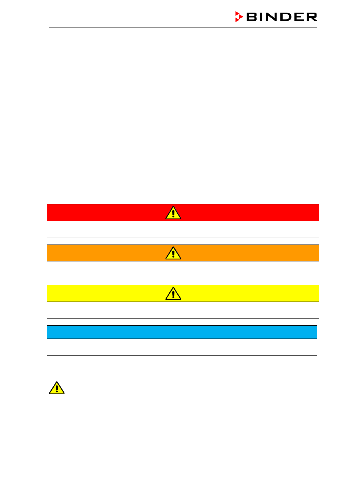
1.4.1 Signal word panel
Depending on the s eriousness and pro bability of serio us consequences, potential dangers are identified
with a signal word, the corresponding safety color, and if appropriate, the safety alert symbol.
DANGER
Indicates an imminently hazardous situation that, if not avoided, will result in death or serious
(irreversible) injury.
WARNING
Indicates a potentially hazardous situation which, if not avoided, could result in death or serious
(irreversible) injury
CAUTION
Indicates a potentially hazardous situation which, if not avoided, may result in moderate or minor
(reversible) injury
NOTICE
Indicates a potentially hazardous situation which, if not avoided, may result in damage to the product
and/or its functions or of a property in its proximity.
1.4.2 Safety alert symbol
Use of the safety alert symbol indicates a risk of injury.
Observe all measures that are marked with the safety alert symbol in order to avoid death or
injury.
CB-S / CB-S-UL (E7) 06/2020 page 7/119
Page 8

Warning signs
Electrical hazard
Hot surface
Explosive Atmosphere
poisoning hazard
or chemical burns
Mandatory action signs
instructions
Environment protection
Wear protective gloves
Wear safety goggles
Prohibition signs
water
1.4.3 Pictograms
Lifting hazard
Harmful substances
Mandatory regulation
Gas cylinders
Biohazard
Read operating
CO
suffocation and
2
Risk of corrosion and /
Disconnect the power
plug
Stability hazard
Pollution Hazard
Lift with several persons
Do NOT touch
Do NOT spray with
Do NOT climb
Information to be observed in order to ensure optimum function of the product.
1.4.4 Word message panel structure
Type / cause of hazard.
Possible consequences.
∅ Instruction on how to avoid the hazard: prohibition
Instruction on how to avoid the hazard: mandatory action
Observe all other n otes and inform ation not necessarily em phasized in the sam e way, in order to avoid
disruptions that could result in direct or indirect injury or property damage.
CB-S / CB-S-UL (E7) 06/2020 page 8/119
Page 9
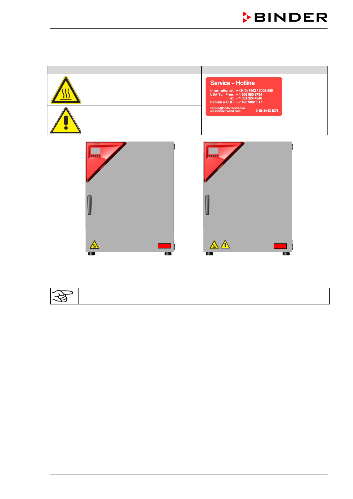
Pictograms (Warning signs)
Service label
Figure 1: Position of labels
Figure 2: Position of labels
1.5 Localization / position of safety labels at the chamber
The following labels are located on the chamber:
Hot surface
Risk of injury (UL chambers only).
Observe the safety instructions in the
operating manual.
on the CO2 incubator CB-S
on the CO2 incubator CB-S-UL
Keep safety labels complete and legible.
Replace safety labels that are no longer legible. Contact BINDER Service for these replacements.
CB-S / CB-S-UL (E7) 06/2020 page 9/119
Page 10
Indications of the type plate
(example)
Information
BINDER
Manufacturer: BINDER GmbH
CB-S 170
Model designation
CO2 Incubator
Device name: CO2 Incubator
Serial No.
000000000000
Serial No. of the chamber
Built
2020
Year of construction
190 °C
374 °F
IP protection
20
Type of IP protection acc. to standard EN 60529
Temp. safety device
DIN 12880
Temperature safety device acc. to standard DIN 12880:2007
Class
3.1
Class of temperature safety device
Art. No.
9040-0189
Art. No. of the chamber
Project No.
---
Optional: Special application acc. to project no.
1,30 kW
Nominal power
6,1 A
Nominal current
200-230 V / 50 Hz
200-230 V / 60 Hz
1 N ~
Current type
Nominal temp.
190 °C
1,30 kW / 6,1 A
374 °F
200-230 V / 50 Hz
IP protection
20
200-230 V / 60 Hz
Safety device
DIN 12880
1 N ~
Class
3.1
Art. No.
9040-0189
Project No.
Built
2020 CO2 Incubator
BINDER GmbH
www.binder-world.com
CB-S 170
E7
Serial No. 00000000000000
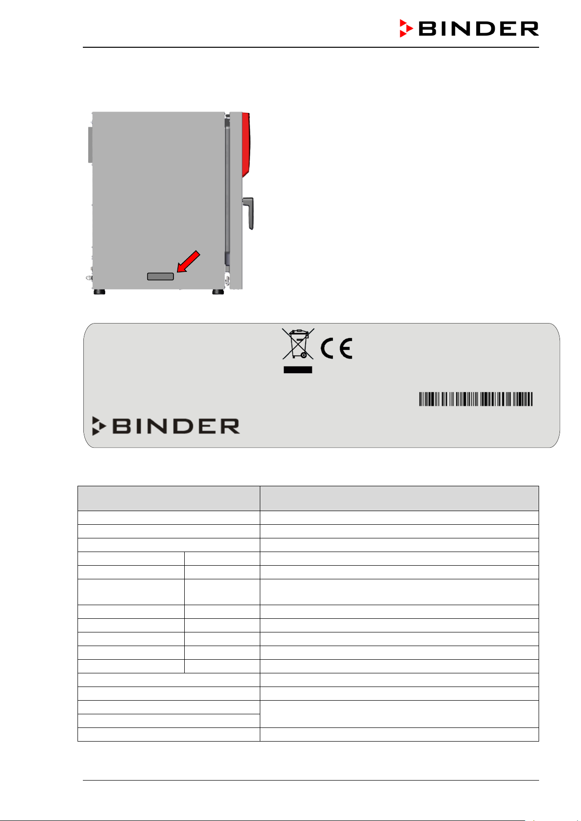
1.6 Type plate
Position of type plate: left chamber side (seen from front), at the bottom in the middle.
Figure 3: Position of type plate
Figure 4: Type plate (example CB-S 170 standard chamber, 9040-0189)
Nominal temperature
Im Mittleren Ösch 5
78532 Tuttlingen / Germany
Nominal temperature
Made in Germany
CB-S / CB-S-UL (E7) 06/2020 page 10/119
Nominal voltage range +/- 10%
at the indicated power frequency
Page 11
Symbol on the type plate
Information
CE conformity marking
Electrical and electronic equipment manufactured / placed on
the market in the EU after 13 August 2005 and to be disposed of
in a separate collection according to Directive 2012/19/EU on
waste electrical and electronic equipment (WEEE).
1.7 General safety instructions on installing and operating the chamber
With regard to operat ing the chamber and to the installation location, please o bserve the local and national regulations rel evant for your country (for Germ any: DGUV guidelines 213-850 on saf e working in
laboratories, issued by the employers’ liability insurance association).
BINDER GmbH is only respons ible for the safety feat ures of the chamber provided s killed electricians or
qualified personnel authorized by BIND ER perform all m aintenance and rep air, and if com ponents relating to chamber safety are replaced in the event of failure with original spare parts.
To operate the chamber, use only origin al BINDER ac cessories or accessories from thir d-party suppli ers
authorized by BINDER. The user is responsible for any risk caused by using unauthorized accessories.
NOTICE
Danger of overheating due to lack of ventilation.
Damage to the chamber.
∅ Do NOT install the chamber in unventilated recesses.
Ensure sufficient ventilation for dispersal of the heat.
Observe the prescribed minimum distances when installing the chamber (chap.3.4).
Do not install or operate the chamber in ha zar dous lo c ations .
DANGER
Danger of explosion due to combustible du sts or explosive mixtures in the vicinity
of the chamber.
Serious injury or death from burns and / or explo sion pressure.
∅ Do NOT operate the chamber in potentially explosive areas.
KEEP combustible dust or air-solvent mixtures AWAY from the chamber.
The chamber does not dispose of any measures of explosion protection.
DANGER
Danger of explosion due to introduction of flammable or explosive substances in
the chamber.
Serious injury or death from burns and / or explosion pressure.
∅ Do NOT introduce any substance into the chamber which is combustible or explosive at
working temperature.
∅ Do NOT introduce any combustible dust or air-solvent mixture in the inner chamber.
Any solvent contai ned in th e charging m aterial must not b e explosi ve or inflam mable. I.e., irrespecti ve of
the solvent concentrati on in the steam room, NO explos ive mixture with air m ust form. The temperature
inside the cham ber m ust lie belo w the f lash point or b elow the s ublim ation po int of the chargi ng m aterial.
Familiarize yourself with the physical and chemical properties of the charging material, as well as the
contained moisture constituent and its behavior with the addition of heat energy and humidity.
CB-S / CB-S-UL (E7) 06/2020 page 11/119
Page 12

Familiarize yourself with any potential health risk s caused by the ch arging material, the contained m oisture constituent or b y reaction products that m ay arise during the temperature process. Take adequate
measures to exclude such risks prior to putting the CO
incubator into operation.
2
DANGER
Electrical hazard by water entering the chamber.
Deadly electric shock.
∅ The chamber must NOT become wet during operation, cleaning, or maintenance.
∅ Do NOT install the chamber in damp areas or in puddles.
Set up the chamber in a splash-proof manner.
The chambers were produced in accord ance with VDE regulations and were routinely tested in acc ordance to VDE 0411-1 (IEC 61010-1).
During and after a sterilization the temperature of the inner surfaces almost equals the set-point. The
glass door, the glass door handle, and the inner chamber will become hot during a sterilization.
CAUTION
Danger of burning by touching hot chamber parts during or after a sterilization.
Burns.
∅ Do NOT touch the glass door, the glass door handle, the inner surfaces, and door gas-
kets during or after a sterilization.
Danger of injury and damages by the chamber tipping over.
Injuries and damage to the chamber and the charging material
∅ Do NOT load the chamber door with heavy objects while it is open.
WARNING
CB-S / CB-S-UL (E7) 06/2020 page 12/119
Page 13
Always close the valve ev e n with app ar ent l y empty cylinders; screw on the c ap when not in
1.8 Precautions when working with CO2 gas
Carbon dioxide (CO2) in high conce ntrations is hazardous to he alth. It is colorless and almost odorless
and therefore practica lly impercepti ble. Vent out an y CO
or a suitable connection to an exhaust system. We recommend installing a CO
gas that m ay escape via goo d room ventilat ion
2
warning system.
2
DANGER
Danger of suffocation and poisoning by high concentration of CO2 (> 4 Vol.-%).
Death by suffocation.
∅ Do NOT set up chambers in non-ventilated recesses.
Ensure technical ventilation measures.
Observe the relevant regulations for handling CO
Close the CO
supply when decommissioning the chamber.
2
1.9 Precautions when handling gas cylinders
General information for safe handling of gas cylinders:
• Store and use gas cylinders only in well-ventilated locatio ns .
.
2
• Open the gas cylinder valve slowly to avoid pressure surges
• Secure gas cylinders during storage and use against falling (chaining).
• Transport gas cylinders with a cylinder cart, do not carry, roll, or throw them.
•
use. Return gas cylinders with the valve closed.
• Do not open gas cylinders by force. Mark them when dam aged
• Protect gas cylinders against fire, e.g. do not store together with flammable liquids
• Observe relevant regulations for dealing with gas cylinders.
Secure the gas cylinders against falling and other mechanical damage.
WARNING
Risk of injury through sudden release of the stored pressure energy when the valve
safety is torn off.
Injuries.
Secure gas cylinders against falling (chaining).
Transport gas cylinders with a cylinder cart.
The valve of the gas cylinder always must be closed before screwing on or unscrewing the gas hose.
WARNING
Risk of injury through sudden release of the stored pressure energy when opening
the cylinder valve of a not connected cylinder.
Injuries.
Close the gas cylinder valve before connecti ng or remov ing the gas hose.
After connecting the gas cylinder, check all gas connections for leaks (e.g. with leak spray or
diluted soap solution).
CB-S / CB-S-UL (E7) 06/2020 page 13/119
Page 14
1.10 I nte nded use
Observing the instructions in this operating manual and conducting regular maintenance
work (chap. 24) is part of the intended use.
Any use of the chambers that does not comply with the requirements specified in this Operating
Manual shall be considered improper use.
Other applications than those described in this chapter are not approved.
Use
incubators CB-S / CB-S-UL are suitable f or the cultivation of m ammal cells under typical con ditions
CO
2
of approx. 37 °C / 98. 6 °F . The chambers permit s ettin g def ined pH con ditions b y comm on NaHC O
er systems of c ommercial cell media b y k eep in g a n exact CO
atmosphere i ns ide . T he c hambers guaran-
2
tee high humidity inside to avoid osmolarity increasing caused by the evaporation of the cell media.
The chambers are suitable for exact conditioning of harmless materials.
Requirements for the chamber load
Any solvent any solvent must not be explosive and flammable. Components of the charging material must
NOT form an explosive m ixture with air. The operat ing temperature m ust lie below the flash point or below the sublimation point of the c harging m aterial . An y component of the charging material m ust NO T be
able to release toxic gases.
buff-
3
The charging mater ial shall not conta in any corrosi ve ingredients that may damage th e machine com ponents made of stainless steel, aluminum, and copper. Such ingredients include in particular acids and
halides. Any corrosive damage caused by such ingredients is excluded from liability by BINDER GmbH.
The chamber does not dispose of any measures of explosion protection.
DANGER
Explosion or implosion hazard and danger of poisoning through the introduction of
unsuitable loading material.
Poisoning. Serious injury or death from burns and / or explosion pressure.
∅ Do NOT introduce any substance combustible or explosive at working temperature into
the chamber, in particular no energy sources such as batteries or lithium-ion batteries.
∅ NO explosive dust or air-solvent mixture in the inner chamber.
∅ Do NOT introduce any substance which could lead to release of toxic gases.
Contamination of the chamber by toxic, infectious or radioactive substances must be prevented
WARNING
Danger of intoxication and infection through contamination of the chamber with
toxic, infectious or radioactive substances.
Damages to health.
Protect the interior of the chamber from contamination by toxic, infectious or radioactive
substances.
Take suitable protective measures when introducing and removing toxic, infectious or
radioactive material
In case of foreseeable use of the device there is no risk for the user through the integrat ion of the cham ber into systems or by special environm ental or operating conditions in the sense of EN 61010-1:2010.
For this, the intended use of the chamber and all its connections must be observed.
CB-S / CB-S-UL (E7) 06/2020 page 14/119
Page 15

Medical devices
The chambers are not classified as medical devices as defined by the Medical Device Directive
93/42/EEC.
Due to the special demands of the Medical Device Directive (MDD), these chambers are not
qualified for sterilization of medical devices as defined by the directive 93/42/EWG.
Personnel Requirements
Only trained person nel with knowledge of the Oper ating Ma nual can s et up and install the c ham ber, start
it up, operate, clea n, and take it out of operat ion. Service and repairs call f or further technical requirements (e.g. electrical know-how), as well as knowledge of the service manual.
Installation site requirements
The chambers are designed for setting up inside a building (indoor use).
The requirements des cribed in the Operating Manu al for installation s ite and ambient conditions (C hap.
3.4) must be met.
WARNING: If customer should use a BINDER chamber running in non-supervised continuous operation, we strongly recommend in case of inclusion of irrecoverable specimen or
samples to split such specimen or samples and store them in at least two chambers, if this is
feasible.
Relevant regulations for dealing with CO2 and gas cylinders must be observed.
1.11 Foreseeable Misuse
Other applications than those described in chap. 1.10 are not approved.
This expressly incl udes the following misuses ( the list is not exhaustive), which pos e risks despite the
inherently safe construction and existing technical safety equipment:
• Non-observance of Operating Manual
• Non-observanc e of inf ormation and warnings on th e chamber (e.g. co ntro l uni t messages, safet y ide n-
tifiers, warning signals)
• Installation , startup, operation, maintenance and re pair by untrained, insufficiently qualified, or unau-
thorized personnel
• Missed or delayed maintenance and testing
• Non-observance of traces of wear and tear
• Insertion of materials excluded or not permitted by this Operating Manual.
• Non-compliance with the admissible parameters for processing the respective material.
• Failure to comply with the relevant regulations for handling gas cylinders
• Failure to comply with the relevant regulations for handling CO
2
• Operation of the chamber without ventilation measures
• Installation, testing, service or repair in the presence of solvents
• Installation of replacement parts and use of accessories and operating r esources not specified and
authorized by the manufac turer
• Installation , startup, operat ion, maintenance or repair of the c hamber in absence of operating instr uc-
tions
• Bypassing or c hang in g pr ot ec tive systems, operation of the c hamber without the designated prot ect iv e
systems
CB-S / CB-S-UL (E7) 06/2020 page 15/119
Page 16

• Non-observance of messages regarding cleaning and disinfection of the chamber.
• Spilling water or clean ing agent on the cham ber, water penetrating into the c hamber dur ing operat ion,
cleaning or maintenance.
• Cleaning activity while chamber is turned on.
• Operation of the chamber with a damaged housing or damaged power cord.
• Continued operation of the chamber during an obvious malfunction
• Insertion of objects, particularly metallic objects, in louvers or other openings or slots on the chamber
• Human error (e.g. insufficient experience, qualification, stress, exhaustion, laziness)
To prevent these and ot her r isk s from incorrect operation, it is rec om mended the operator issue o per at ing
instructions and standard operating procedures (SOPs).
1.12 Residual Risks
The unavoidable design f eatures of a chamber, as well as its proper f ield of application, can also pose
risks, even during corr ect operation. These residual risk s include hazards which, despite the in herently
safe design, existing technical protective equipment, safety precautions and supplementary protective
measures, cannot be ruled out.
Messages on the chamber and in the Operating Manual warn of residual risks. The consequences of
these residual risk s and the m easures required to prevent them ar e listed in th e Operati ng Manu al. Mor eover, the operator must take measures to minimize hazards from unavoidable residual risks. This includes, in particular, issuing oper ati ng instr uc tions .
The following list s ummarizes the hazar ds against which this Operating Manua l and the Service Manual
warn, and specifies protective measures at the appropriate spots:
Unpacking, Transport, Installati on
• Sliding or tilting the chamber
• Setup of the chamber in unauthorized areas
• Installation of a damaged chamber
• Installation of a chamber with damaged power cord
• Inappropriate site of installation
• Missing protective conductor connection
Normal operation
• Assem bly errors
• Contact with hot surfaces on the housing
• Contact with hot surfaces in the interior and inside of doors
• Emission of non-ionizing radiation from electrical operating resources
• Contact with live parts in normal state
Cleaning and Decontamination
• Penetration of water into the chamber
• Inappropriate cleaning and decontamination agents
• Enclosure of persons in the interior
CB-S / CB-S-UL (E7) 06/2020 page 16/119
Page 17
Malfunction and Damage
• Continued oper ation of the chamber during an obvio us malfunction or outage of the heating or gas
systems
• Contact with live parts during error status
• Operation of a unit with damaged power cord
Maintenance
• Maintenance work on live parts.
• Execution of maintenance work by untrained/insufficiently qualified personnel
• Electrical safety analysis during annual maintenance not performed
Trouble-shooting and Repairs
• Non-observance of warning messages in the Service Manual
• Trouble-shooting of live parts without specified safety measures
• Absence of a plausibility check to rule out erroneous inscription of electrical components
• Performance of repair work by untrained/insufficiently qualified personnel
• Inappropriate repairs which do not meet the quality standard specified by BINDER
• Use of replacement parts other than BINDER original replacement parts
• Electrical safety analysis not performed after repairs
1.13 O perating instructions
Depending on the appl ication and location of the chamber , it is recommended that the operator of the
chamber provides the re lev ant inf orm ation f or saf e op eratio n of the c ham ber in a s et of oper ating instr uctions.
Keep these operating instructions with the chamber at all times in a place where they are
clearly visible. They must be comprehensible and written in the language of the employees.
CB-S / CB-S-UL (E7) 06/2020 page 17/119
Page 18

1.14 Measures to prevent accidents
The manufacturer took the following measures to prevent dangers:
• Indications on the type plate
See operating manual chap. 1.6.
• Operating manual
An operating manual is available for each chamber.
• Overtemperature monitoring
The chamber is equipped with a temperature display, which can be read from outside.
The chamber is equipped with an additional saf et y controller (tem peratur e saf ety device c lass 3.1 ac c.
to DIN 12880:2007). Visual and audible (buzzer) signals indicate temperature exceeding.
• Safety, measurement, and control equipment
The safety, measuring, and control equipment is easily accessible.
• Electrostatic ch arg e
The interior parts are grounded.
• Non-ionizing radiation
Non-ionizing radiatio n is not intentionall y produced, but release d only for technical reas ons by electrical equipment (e.g. power cables). T he machine is equipped with no per manent magnets. If persons
with active implants ( e.g. pacemaker s, defibrillators) keep a safe distance (distan ce of field source to
implant) of 30 cm, an influence of these implants can be excluded with high probability.
• Protection against touchable surfaces
Tested according to EN ISO 13732-1:2008.
• Floors
See operating manual chap. 3.4 for correct installation
• Cleaning
See operating manual chap. 22.1.
CB-S / CB-S-UL (E7) 06/2020 page 18/119
Page 19

2. Chamber description
The CO2 incubators CB-S / CB-S-UL series were produc ed with great care using the latest tools for development and produc ti on. They can be oper at ed in a t emperature range from 6 °C / 10.8 °F ab ove ambient temperature up to +50 °C / 122°F and a CO
equipped with a m icroprocessor contr oller for tem perature and CO
to one-tenth of a degree resp. 0.1 vol.-%. T he y are availab le in dif f erent voltages .
Material: The inner cham ber, the pre-h eating cham ber and the ins ide of the d oors are all made of s tainless steel V2A (German materia l no. 1.4301, US equivalent AISI 304). The inner surfaces are smooth and
therefore easy to clean. T h e inner cham ber is deep-drawn from one p iece, p olis hed (s uitab le f or pharm aceutical applications) and has no welds or inaccessible corners. The hinges and the seal of the inner
glass door are glue d from the outside to aid cl eaning of the inner c ham ber. When op erating the cham ber
at high temperatures (sterilization), the im pact of the oxygen in the air may cause discoloration of the
metallic surfaces (yellowish-brown or blue) b y natural oxidation processes. T hese colorations are harmless and will in no way impair the function or quality of the chamber.
The perforated she lv es are also made of s ta in les s s te el (German mater ial no . 1.4016, US equ ival ent AISI
430). You can insert a maximum of 6 (CB-S / CB-S-UL 170) bzw. 8 (CB-S / CB-S-UL 260) shelves.
The housing is RAL 7 035 powder-coated. All corners and edges are also c ompletely coate d. The standard chamber door is hinged right. The chamber is optionally available with the door hinged left.
Sterilization: The heating system of the chamber permits hot-air auto-sterilization at 190 °C / 374 °F.
Thus, a temperature of at least 180 °C / 356 °F is maintained on al l inter na l s urf ac es , r esulti ng i n ster i lization of the entire inner chamber.
range of 0 vol.-% up t o 20 vol.-%. The chamber s are
2
levels and a dig ital display accurat e
2
Safety: T hanks to the standard s afety devic e (class 3.1 accord ing to DIN 12880:2007), the set t emperature is maintained in case of failure.
An error diagnost ics system monitors the c hamber functions and ge nerates audible and visual warning
and alarm messages. The door is monitored for being closed.
The controller provid es access control by com bining password pr otection with diff erent authorizati on levels.
system: A highly pre cise, drift-free CO2 infrared measuring s ystem in combination with the p erma-
CO
2
nent mixture of CO
precise and constant CO
gas through a special proprietary gas mixing head developed by BINDER allows
2
concentrations for long per iods. This creates optimum growth conditions for
2
cultures. The gas ent er s the c hamber via a fine filter (aseptic f ilt er ) with a h ig h f ilt r ation ef f iciency that also
filters the smallest particles.
The CO
sensor can be re m oved fr om the inner ch amber by hand and cleaned with s uita ble d etergent s if
2
needed.
Fast reaction times , maximum accurac y and selectivity charac terize the CO
chamber. The accurac y of the CO
measuring s ystem is based on an infrar ed measuring cell with NDIR
2
m easuring procedure of the
2
(non-dispersive inf rared) sensor, which continuously regul ates to a reference value. Therefore, distur bance variables an d aging phenom ena in th e meas uring s ystem are almost completel y elim inated, so that
this measuring system , in contrast to other measuring procedures , remains practic ally drift-free bet ween
calibrations and is entirely selective for CO
The CO
depends on the num ber of CO
measuring cell contains a measuring section inside, in which the absorption of infrared light
2
molecules in the be am path. This number of CO2 molecules changes with
2
.
2
the ambient press ure in relation t o a constant volume. The d istances between the molecules are consequently pressure-dependen t. T he collisio n frequenc y of the IR-beam with CO
molecules incr eases there-
2
fore by increasing pressure . For this reason, the am bient pr essure m ust be com pensate d in or der to cor rect the displa y readin g of t he CO
concentratio n i n vol .-%. This is achieved b y en tering the altitude of the
2
site above the sea (chap. 6.4).
Controller: T he efficient RD4 chamber controller is equipped with a m ultitude of operating functions, in
addition to recorder an d a la rm functions. Set-point entr y is easil y accom plished accurate to one-tenth of a
degree resp. 0.1 vol.-% directly via t he chamber contr oller and is also poss ible directly with a c omputer
via Intranet in connecti on with the APT-COM™ 4 Mu lti Management Software (option, chap. 20.4). The
controller provides password protection for the setting menus. An error diagnostics system generates
audible and visual alarm messages.
CB-S / CB-S-UL (E7) 06/2020 page 19/119
Page 20
(2)
(3)
(1)
Data monitoring and recording: The chamber is regularly equipped with a zero-voltage relay alarm
output (chap. 15.5) and optionally with analog outputs (chap. 20.6) for integration into customer systems.
The chamber is regularly equipped with an Ethernet interface for computer communication, enabling
monitoring via a netw ork. The BINDER APT-COM™ 4 Multi Managem ent Software (option, chap. 20.4)
permits network ing of up t o 100 ch am bers and con nection to a c om puter, as well as r ecordin g and re presenting temperature and CO
data.
2
A dat a logger independ ent from the cham ber controller (optio n, chap. 20.5) s erves to independentl y record the temperature values, data given out in compliance with FDA guideline 21 CFR part 11.
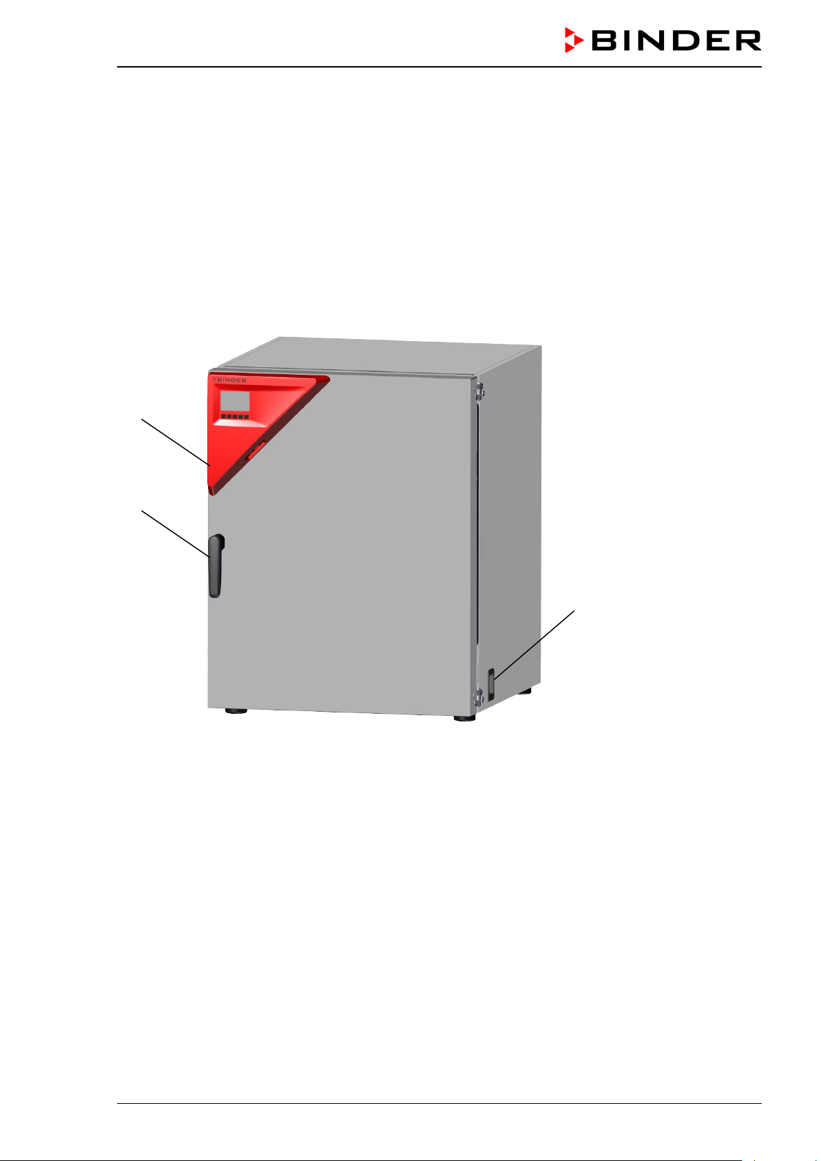
2.1 Chamber overview
Figure 5: CO
incubator CB-S / CB-S-UL (example CB-S 170), closed
2
(1) Triangle instrument panel w ith RD4 controller for temperature and CO
2
(2) Door handle
(3) Main power switch
CB-S / CB-S-UL (E7) 06/2020 page 20/119
Page 21
(11) (10) (9) (8) (1)
(4) (5) (6)
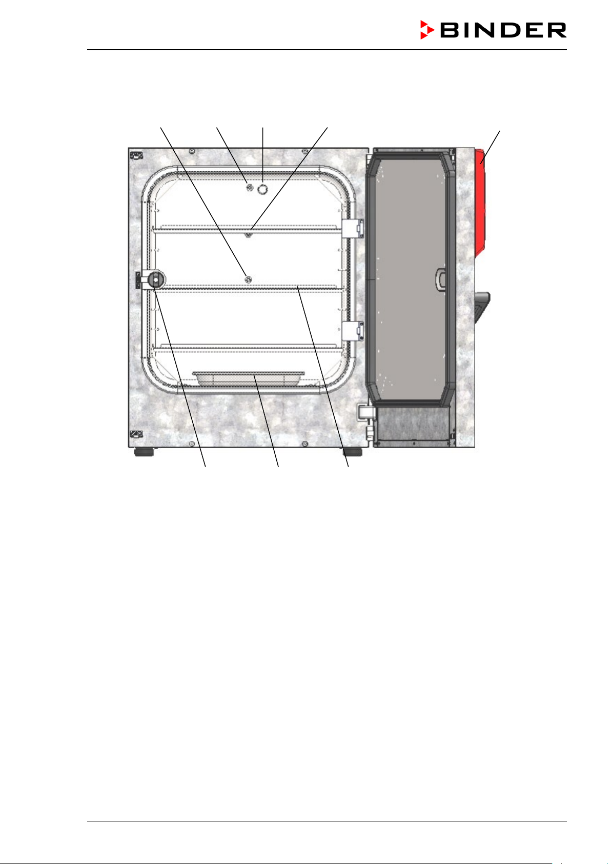
2.2 Inner chamber
Figure 6: CO
incubator CB-S / CB-S-UL (example CB-S 170), outer door open
2
(1) Triangle instrument panel with RD4 controller for temperature and CO
(4) Glass door handle
(5) Water pan
(6) Shelves
(7) (not used)
(8) Pt 100 temperature sensor
(9) CO
(10) Gas mixing head for CO
sensor
2
2
(11) Silicone measuring port in the glass door
2
CB-S / CB-S-UL (E7) 06/2020 page 21/119
Page 22
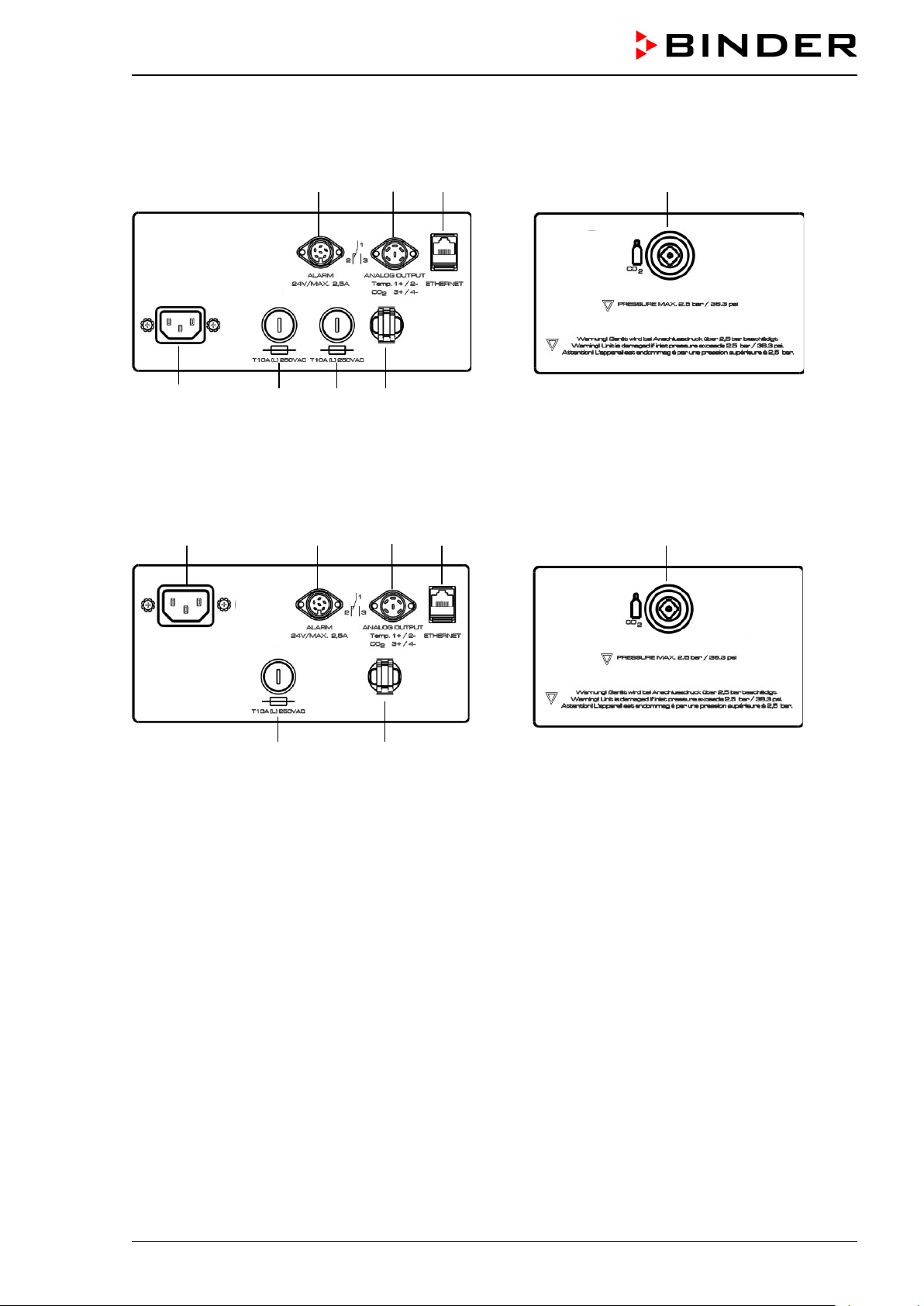
2.3 Connection panel on the rear of the chamber
(13) (14) (15) (18)
(12a) (16a) (16a) (17)
Figure 7: Rear control panel C with options
(12b) (13) (14) (15) (18)
(16b) (17)
Figure 8: Rear control panel C-UL with options
(12a) Socket for IEC connector plug / power cable 230 V AC for C
(12b) Socket for IEC connector plug / power cable 100-120 V AC for C-UL
(13) DIN-socket for zero-voltage relay alarm outputs
(14) DIN socket for analog outputs 4-20 mA (av ai lab le b y BINDER INDI VUD U AL Cus t omized Solutions)
(15) Ethernet interface for computer communication
(16a) Miniature fuse T10 A (L) 250 V AC for C
(16b) Miniature fuse T12,5 A (L) 250 V AV for C-UL
(17) Strain relief for power cable
(18) Quick acting closure socket for CO
2
CB-S / CB-S-UL (E7) 06/2020 page 22/119
Page 23
2.4 Chamber doors
The outer chamber door is equipped with a heater on its inner side. The do or must be closed while t he
chamber is operating normally in order to ensure stable climatic conditions in the inner chamber.
An additional glass door enables vi ewing of the s amples witho ut disturbi ng the tem peratur e in the interior
and contaminating the samples sealing the interior of the chamber.
When the outer door is open, the CO
Delay time for the temperature and CO
After closing the outer door, the tolerance range alarm is turned off for a programmable delay
time. This prevents alarms being constantly triggered during the unstable operating phase
after opening the outer door.
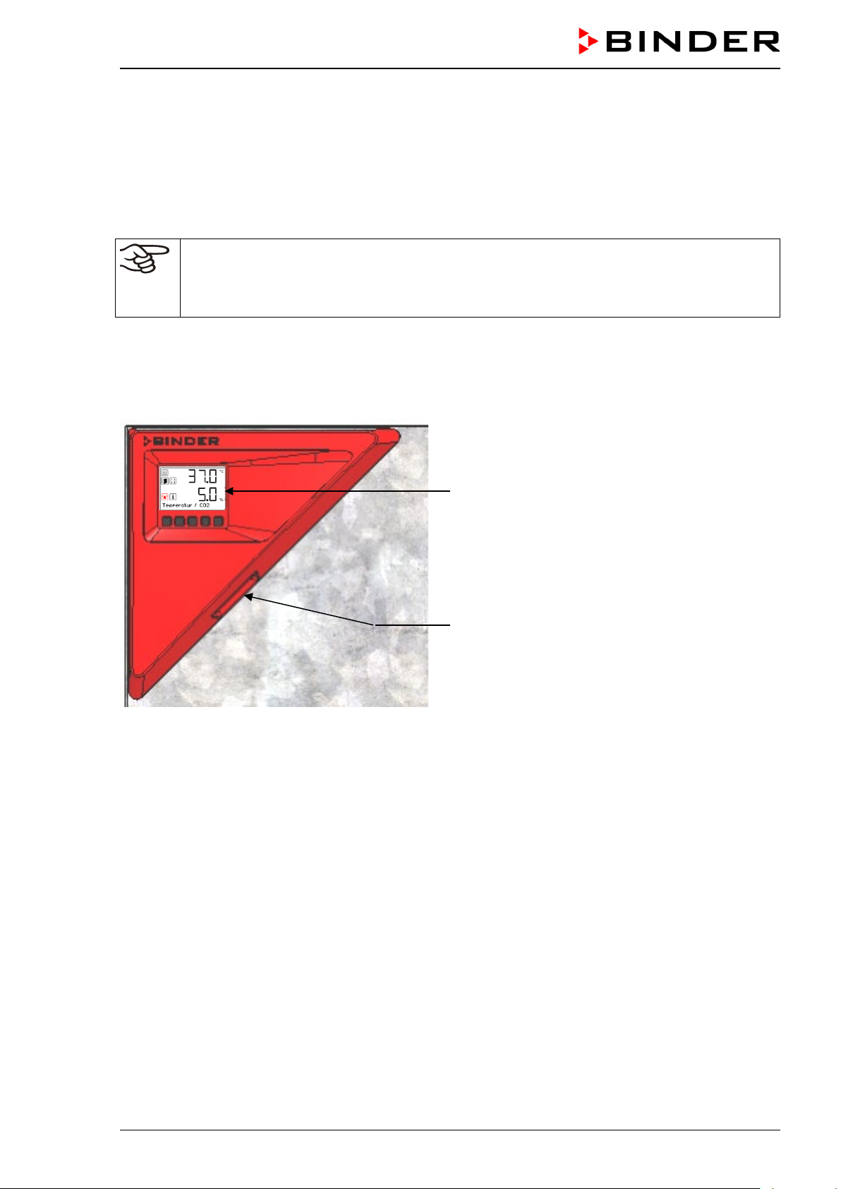
2.5 Ins trum ent panel
intake valve automatically closes.
2
tolerance range alarm :
2
RD4 controller display
USB interface
Figure 9: Instrument panel with RD4 controller and USB interface
CB-S / CB-S-UL (E7) 06/2020 page 23/119
Page 24
r corners with the aid of
3. Completeness of delivery, transportation, storage, and installa-
tion
3.1 Unpac king, and checking equipment and completeness of delivery
After unpacking, p lease check the chamber and its optiona l accessories, if any, based on t he delivery
receipt for completenes s and for transportation dam age. Inform the carrier immediate ly if transportation
damage has occurred.
The final tests of the manufacturer may have caused traces of the shelves on the inner surfaces. This has
no impact on the function and performance of the chamber.
Please remove an y transportati on protection devices and adh esives in/o n the chamber and o n the doors
and remove the operating manuals and accessory equipment.
For transport purpos e, a silica gel bag for dryin g purpose was added. Do not e at! Do not open the silica
gel bag and dispose of it with normal waste.
Remove any protective lamination sheet on the inner metal surfaces prior to commissioning.
CAUTION
If you need to return the chamber, please use the original packing and observe the guidelines for safe
lifting and transportation (chap. 3.2).
For disposal of the transport packing, see chap. 25.1.
Note on second-hand chambers (Ex-Demo-Units):
Second-hand chambers are chambers that were used for a short tim e for tests or exhibitions. They are
thoroughly tested before resale. BINDER ensures that the chamber is technically sound and will work
flawlessly.
Second-hand chambers are marked with a sticker on the chamber door. Please remove the sticker before
commissioning the chamber.
Risk of injury and damages by lifting heavy loads and by sliding or
tilting of the chamber due to improper lifting.
Injuries, damage to the chamber.
∅ Do NOT lift or transport the chamber using the door handle or the door.
Lift the chamber from the pallet at the four lo we
four people.
CB-S / CB-S-UL (E7) 06/2020 page 24/119
Page 25
Lift the chamber at the four lower corners with the aid of 4 people and plac e it on a
ed location and lift it f rom the rolling pallet with the aid of
3.2 Guidelines for safe lifting and transportation
After operation, please observe the guidelines for temporarily decommissioning the chamber (chap. 25.2).
Empty the water pan befor e moving the incubator. In c ase of any spilling of the contents , shut down the
incubator and dry it out carefully and completely
CAUTION
Risk of injury and damages by lifting heavy loads and by sliding or tilting of the
chamber due to improper transportation.
Injuries, damage to the chamber.
Transport the chamber in its original packaging only.
For moving or shipping, secure the chamber with transport straps.
∅ Do NOT lift or transport the chamber using the door handle or the door.
rolling pallet.
Move the chamber to the d es ir
four people.
• Permissible ambient temperature range for transport: -10 °C / 14°F to +60 °C / 140°F.
You can order transport packing and rolling pallets for transportation purposes from BINDER Service.
3.3 Storage
Intermediate storage of the chamber is possible in a closed and dry room. Observe the guidelines for
temporary decommissioning (chap. 25.2).
• Permissible ambient temperature range for storage: -10 °C / 14°F to +60 °C / 140°F.
• Permissible ambient humidity: max. 70% r.h., non-condensing
When after storage in a co ld location you transf er the chamber to its warm er installation site, condensation may form in the inner chamber, on the hous ing or in the sensor com partment of the CO
ment. Before start-up, wait at least one hour until the CO
incubator h as attained ambient temperature
2
measure-
2
and is completely dry.
3.4 Location of installation and ambient conditions
Notes on the location of installation
Set up the chamber on a f lat, even surf ace, free f rom vibration and in a well-ventilated, dr y location. The
chambers are designed for setting up inside a building (indoor use).
Freestanding chambers are s uitable for installation on tables or on the optionally available st and. Note:
The site of installa tion must be capable of supportin g the chamber’s weight (see t echnical data, chap.
26.4).
Align the chamber using a spirit level to ensure even covering of the cell-cultures with the m edium. For
this purpose, manually adjust the four incubator feet.
In order to avoid contamination, never place the chamber directly on the floor.
CB-S / CB-S-UL (E7) 06/2020 page 25/119
Page 26
NOTICE
Danger of overheating due to lack of ventilation.
Damage to the chamber.
∅ Do NOT install the chamber in unventilated recesses.
Ensure sufficient ventilation for dispersal of the heat.
Observe the prescribed minimum distances when installing the chamber.
Do not install or operate the chamber in potentially explosive areas.
DANGER
Danger of explosion due to combustible du sts or explosive mixtures in the vicinity
of the chamber.
Serious injury or death from burns and / or explo sion pressure.
∅ Do NOT operate the chamber in potentially explosive areas.
KEEP explosive dust or air-solvent mixtures AWAY from the vicinity of the chamber.
Ambient conditions
• Permiss ible ambient t em peratur e range f or oper ation: +18 °C / 64 .4 °F up to +30 °C / 86 °F. At elevat-
ed ambient temperature values, fluctuations in temperature can occur.
• Ideal ambien t temperature: by at l east 6 °C / 10.8 °F below the intended working temperature. E.g.,
working temperature 37 °C / 98.6 °F – resulting p ermitted ambient tem perature 31 °C / 87.8 °F and
lower
In the event of working t emperatures of less than 6 °C / 10. 8 °F above the ambient tem perature, the se t
point can be exceeded.
Do not place the chamber directly below the air outlet of an air conditioner.
The ambient temperature should not be substantially higher than the indicated ambient temperature of +22 °C +/- 3 °C / 71.6 °F ± 5.4 °F to which the specified technical data relate. For
other ambient conditions, deviations from the indicated data are possible.
Avoid direct solar radiation on the chamber.
Avoid strong drafts, e.g. by air conditioning.
• Permissible ambient humidity: 70% r.h. max., non-condensing.
• Installation he ight: max . 2000 m / 6562 ft. above sea level. After the incubator ha s been turned on f or
the first time, enter the altitude of the site above sea level into the RD4 controller (chap. 6.4).
• Wall distances: rear 100 mm / 3.94 in, sides 50 mm / 1.97 in.
To completely separate the chamber from the power supply, you must disconnect the power
plug. Install the chamber in a way that the power plug is easily accessible and can be easily
pulled in case of danger.
• Avoid any conduc tive dust in the ambiance according to the cham ber layout compl ying with pollution
degree 2 (IEC 61010-1).
CB-S / CB-S-UL (E7) 06/2020 page 26/119
Page 27
Notes on handling carbon dioxide (CO
Carbon dioxide (CO
) in high conce ntrations is hazardous to he alth. It is colorless and almost odorless
2
and therefore practica lly impercepti ble. Vent out an y CO
or a suitable connection to an exhaust system. We recommend installing a CO
)
2
gas that m ay escape via goo d room ventilat ion
2
warning system.
2
DANGER
Danger of suffocation and poisoning by high concentration of CO2 (> 4 Vol.-%).
Death by suffocation.
∅ Do NOT set up chambers in non-ventilated recesses.
Ensure technical ventilation measures.
Observe the relevant regulations for handling CO
Observe the occupational exposure limit OEL for CO2 set b y the national authorities (formerl y maximum permitted work place concentration) . Check complianc e when operating a ll chambers located in the
room.
• OEL for Germany: 5000 ml/m3 (ppm) = 0,5 Vol.-%
• CO
lost with eac h door o pening: about 16.4 g , i.e. 0.0084 c ubic m eters / 0.29 6 cubic fee t (under nor-
2
mal pressure)
• CO
lost during 12h at 5 vol.-% without door opening: approx. < 2 g, i.e. 0. 001 cubic meters / 0.035
2
cubic feet (under normal pressure 1013 mbar / 14.7 psi)
An example of how to evaluate laboratory volume and air change rate:
.
2
Question: Is an air ch ange rate of 1/h suffic ient for a lab with a volum e of 100 cubic meters / 3,531.5
cubic feet with 10 CO
Calculation: CO
incubators, opened 4 times per hour?
2
concentration = CO2 lost by door opening, m ultiplied by 10 chambers, multiplied by 4
2
door openings per hour, divided by lab volume
0.0084 cubic meters x 10 x 4 div. 100 cubic meters = 0.00336, i.e. 0.336% or 3360 ppm.
0.296 cubic feet x 10 x 4 div. 3,531.5 cubic feet = 0.00336, i.e. 0.336% or 3360 ppm.
Result: The maximum permissible value of 5000 ppm is not exceeded under these operation conditions.
Even when CO
or systems operated with CO2 are handled caref ully and appropriately, a residual risk
2
remains, which can lead to life-threatening s ituations under certain circum stances . Therefore we str ongly
recommend continuo us monitoring of CO
be ensured permanently that the maximum permissible occupational exposure limit OEL for CO
% CO
for Germany) is not exceeded.
2
concentration in the am bient air of the CO2 incubator. It must
2
(0.5 vol -
2
CB-S / CB-S-UL (E7) 06/2020 page 27/119
Page 28
4. Installation and connections
4.1 Shelves
You can put the she lves in differ ent positions at the line of c hannel beads in th e inner c ham ber. Hold th e
shelf straight and then insert it so it will go smoothly inside the chamber.
Permitted shelf loads:
Maximum load on one single shelf: 10 kg / 22 lb
Maximum total load on all shelves: 40 kg / 88 lb
4.2 CO2 sensor
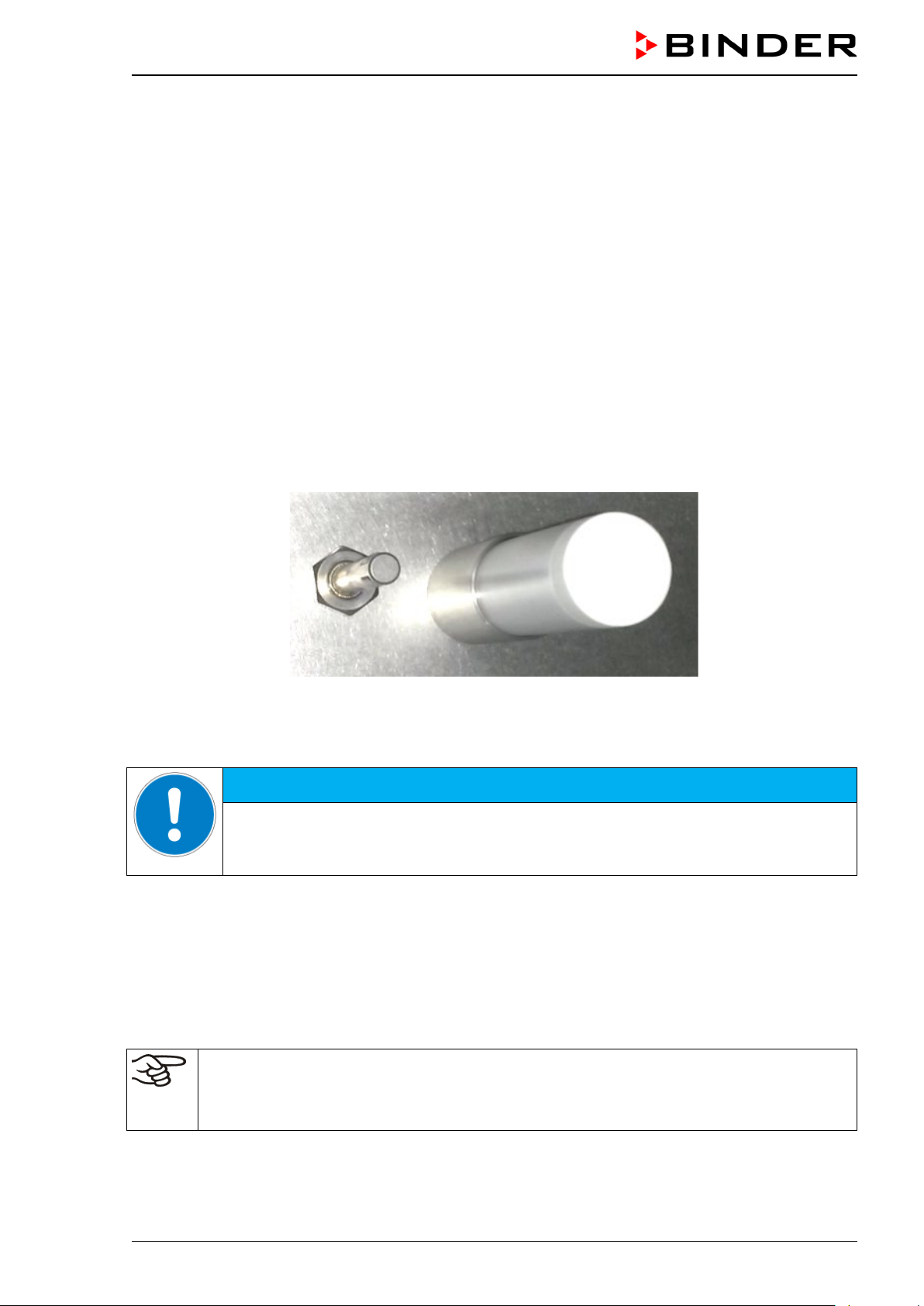
4.2.1 Connecting the CO2 sensor
Turn off the chamber. Open the door of the inner cham ber and plug the CO2 sensor (4) into the permanently installed holding tube located in the upper part of the rear of the inner chamber.
Figure 10: Plugged-in CO
sensor (right) and gas mixing head for CO2
2
The sensor must click in correctly and sit tightly in the connection socket.
NOTICE
Danger of damage to the CO2 sensor by connecting or removing it during operation.
Damage to the CO
Connect or remove the CO
4.2.2 General notes
Connect or remove t he CO2 sensor without rotati ng and only when the incubator is turned off. Remove
the CO
and humidity from intrudin g into the m easuring c ell. It is avai lable as a spare part. Re place it whene ver it
is damaged or soiled.
sensor before r emov ing or rep lacing its filter cap. T he PTF E filter of the CO2 sensor prevents dirt
2
The accuracy of the indicated values of CO
0.08 vol.-% per 10 mbar / 0.15 psi). In order to compensate this effect when measuring the
concentration, the altitude of the installation site above sea level can be entered into the
CO
2
controller (chap. 6.4).
sensor.
2
sensor only with the chamber turned off.
2
depends on the ambient air pressure (approx.
2
CB-S / CB-S-UL (E7) 06/2020 page 28/119
Page 29
NOTICE
NOTICE
NOTICE
The CO
sensor is temperature resistant up to a maxi m u m temperature of 60 °C / 140 °F.
2
Danger of damage to the CO2 sensor by excess temperature.
Damage to the CO
∅ Do NOT autoclave the CO
∅ Do NOT expose the CO
sensor.
2
Sensor.
2
sensor to hot-air sterilization..
2
The CO
sensor he ad was especiall y adjusted for the specific c hamber . To avoid confusion, an adhes ive
2
label with a ser ial num ber is adh ered to the sens or head. W hen ex changi ng the sensor, you m ust repeat
the CO
adjustment.
2
Danger of confusing CO2 sensors.
Invalid calibration.
Do NOT change the CO
Note down the serial number of the CO
sensor head.
2
sensor.
2
Avoid strong shocks when handling the CO2 sensor.
Danger of damage to the CO2 sensor by shocks.
Damage to the CO
Avoid strong shocks of the CO
sensor.
2
sensor (by putting it down hard, or dropping).
2
4.3 Water pan
The water pan permits high humidity without condensation on the inner walls of the CO2 incubator.
Place the water pan in central position on the bottom of the inner chamber. Place the wat er pan with its
narrow side centrally between the front cams on the bottom of the inner chamber.
Figure 11: Position of the water pan centr all y betwee n the front cams (arrows)
CB-S / CB-S-UL (E7) 06/2020 page 29/119
Page 30
Always close the valve ev e n with app ar ent l y empty cylinders; screw on the c ap when not in
Make sure that the water pan has firm contact with the inner chamber bottom and rests tightly on it.
Fill the water pan with 1 liter of distilled, sterilized water.
We recommend c leaning (chap. 22.1) and refil ling the pans 2 to 3 times a week. F or evacuat ion, rem ove
the water pan.
We recommend using dis tilled, sterile water to achieve optim um growth results. Any corrosive dam age
that may arise following use of water of different quality or by additives is excluded from the liability
agreement.
If required, you ca n ad d micr obiologicall y inhibiti ng su bstances s uch as c opper c hips, copper s ulphate or
ethylene diamine tetra-vinegar acid (EDTA) in a concentration of
Empty the water pan bef ore moving the incub ator . In c as e of the c ont ents s p illi n g, im mediately shut down
the incubator and dry it carefully and completely.
1 to 5 mmol/l.
4.4 Gas connection
General information for safe handling of gas cylinders:
• Store and use gas cylinders only in well ventilated areas.
• Open the gas cylinder valve slowly to avoid pressure surges
• Secure gas cylinders during storage and use against falling (chaining).
• Transport gas cylinders with a cylinder cart, do not carry, roll, or throw them
•
use. Return gas cylinders with the valve closed
• Do not open gas cylinders by force. Mark them when damaged
• Protect gas cylinders against fire, e.g. do not store together with flammable liquids
• Observe relevant regulations for dealing with gas cylinders.
Secure the gas cylinders against falling and other mechanical damage.
WARNING
Risk of injury through sudden release of the stored pressure energy when the valve
safety is torn off.
Injuries.
Secure gas cylinders against falling (chaining).
Transport gas cylinders with a cylinder cart.
The valve of the gas cylinder always must be closed before screwing on or unscrewing the gas hose.
WARNING
Risk of injury through sudden release of the stored pressure energy when opening
the cylinder valve of a not connected cylinder.
Injuries.
Close the gas cylinder valve before connecting or removing the gas hose.
After connecting the gas cylinder, check all gas connections for leaks (e.g. with leak spray or
diluted soap solution).
CB-S / CB-S-UL (E7) 06/2020 page 30/119
Page 31

NOTICE
4.4.1 Connecting the CO2 gas cylinder
Carbon dioxide (CO2) in high conce ntrations is hazardous to he alth. It is colorless and almost odorless
and therefore practica lly impercepti ble. Vent out an y CO
or a suitable connection to an exhaust system. We recommend installing a CO
gas that m ay escape via goo d room ventilat ion
2
warning system.
2
DANGER
Danger of suffocation and poisoning by high concentration of CO2 (> 4 Vol.-%).
Death by suffocation.
∅ Do NOT set up chambers in non-ventilated recesses.
Ensure technical ventilation measures.
Observe the relevant regulations for handling CO
Close the CO
supply when decommissioning the chamber.
2
The CO2 gas necessary for operation must have a technical grade of 99.5 %.
The gas connections must be established by qualified personnel who are trained in handling
the respective gases and familiar with the required safety measures.
.
2
The following steps are required:
Ensuring the correct CO
output pressure
2
A gas supply pressure above 2.5 bar / 36 psi will result in chamber damage.
Use a pressure r educer and make sur e to avoid any exc essive outlet pressure when connecting the
gas hose to the incubator.
The real outlet pressure of gas cylinders, s ets of gas cylinder s or central gas sup plies am on the s econd manometer must not exceed 2.5 bar / 36 psi.
Danger of damage by excessive outlet pressure > 2.5 bar / 36 psi.
Damage to the chamber.
∅ The outlet pressure must NOT exceed the indicated value of 2.5 bar / 36 psi.
Before connecting, chec k the outlet pressur e on the pressure r educer of the cylin-
der.
Adjust the outlet pressure to 2.0 bar / 29 psi above the ambient pressure.
Observe the correct outlet pressure also when replacing the gas cylinders.
Establishing the connection to the inc u b ator
Connect the supp lied gas hose ( internal diam eter 6 mm / 0.24 inches) to t he pressur e reducer of th e
gas cylinders or central gas supply and secure the connection with the supplied hose clamp.
Connect the pre-assem bled hose nozzle of the gas hose to the quick acting closure s ocket (14) DN 6
on the chamber rear, as described in chap. 4.4.2.
Leak test
After connecting th e g as c ylin der, c h ec k all gas connections f or l eak s ( e.g. with le ak spray or diluted soa p
solution).
CB-S / CB-S-UL (E7) 06/2020 page 31/119
Page 32

(a)
(c)
(b)
The recovery times of the gas concentrations inside the chamber after opening the door are
indicated in the technical data (chap. 26.4) and refer to a connection pressure of 2.0 bar / 29
psi. Decreasing supply pressure will result in longer recovery times.
Conversion table for gas inlet pressures, bar – psi, see chap. 26.6.
4.4.2 Connecting the gas hose to the chamber rear
The gas hose, which will be us ed to est ablish the c onnec tion to a gas cylinder, is already attached to the
hose nozzle and sec ured b y a hose c lamp. Pl ug the h ose nozzl e into the correspond ing quic k acting c losure socket (a) loc ated at the r ear of the chamber. This quick acting c losure s ocket is cl osed b y a rubber
cover (b).
Only use the supplied hose nozzle to connect to the quick acting closure socket.
Otherwise, the quick acting closure socket may leak, and/or it may become impossible to con-
nect the original hose nozzle. In this case, please contact BINDER Service.
Remove the rubber cover (b) by pulling it off.
Chamber rear
Figure 12: Connection of the hose lead to the gas cylinder
Now fit the hose nozzle ( c) in the quick acting closure socket. To remove the connecti on, pull the hose
nozzle off the quick acting closure socket.
CB-S / CB-S-UL (E7) 06/2020 page 32/119
Page 33

The gas cylinder connection kit for CO2 (Art. no. 8012-0014) includes the
4.4.3 Gas cylinder connection kit (option)
following parts for connecting a gas cylinder to the CO2 incubator:
• Pressure reduc er with manometers for cylinder pressure (high pressure
gauge) and outlet pressure (low pressure gauge)
• 5 m press ure hose with pre-as sembled hose no zzle for quick acting closure socket
• 1 hose clamp to connect the gas hose to the pressure reducer
The pressure reducer is also available as an individual accessory.
Figure 13: Gas cylinder connection kit
NOTICE
Danger of damage by excessive outlet pressure > 2.5 bar / 36 psi.
Damage to the chamber.
∅ The outlet pressure must NOT exceed the indicated value of 2.5 bar / 36 psi.
Before connecting, check the outlet pressure on the pressure reducer of the cylinder.
Adjust the outlet pressure to 2.0 bar / 29 psi above the ambient pressure.
The gas connections must be established by qualified personnel who are trained in handling
the respective gases and familiar with the required safety measures.
CB-S / CB-S-UL (E7) 06/2020 page 33/119
Page 34

4.5 Electrical connection
The chambers are supplied ready for connection. They come with an IEC connector plug.
Model Power plug
CB-S 170
CB-S 170-UL
CB-S 260
CB-S 260-UL NEMA 5-20P
• The dom estic socket must also pr ovide a protective c onductor. Make sure that the connection of the
protective conductor of the domes tic installatio ns to th e cham ber’s protec tive co nductor m eets the la test technology. The protective conductors of the socket and plug must be compatible!
Grounded plug
IEC 7/7
NEMA 5-20P
Grounded plug
IEC 7/7
Nominal voltage +/- 10% at the
indicated power frequency
200-230 V at 50 Hz
200-230 V at 60 Hz
100-120 V at 50 Hz
100-120 V at 60 Hz
200-230 V at 50 Hz
200-230 V at 60 Hz
100-120 V at 50 Hz
100-120 V at 60 Hz
Current
type
1N~ 10 A
1N~ 16 A
1N~ 10 A
1N~ 16 A
Chamber
fuse
DANGER
Electrical hazard due to missing protecti ve conductor connection.
Deadly electric shock.
Make sure that the ch am ber’s po wer plu g and th e po wer soc k et m atch and sec ure-
ly connect the electr ical pr otec tive con ductors of th e ch am ber and th e hous e insta llation.
• Only use original connection cables from BINDER according to the above specification.
• Prior to con nection and s tar t-up, chec k the po wer su ppl y voltag e. Com par e the v alues to t he sp ecif ied
data located on the chamber’s type plate (centrall y located at the bottom of the left-hand si de of the
chamber, see chap. 1.6).
NOTICE
Danger of incorrect power supply voltage due to improper connection.
Damage to the chamber.
Check the power supply voltage before connection and start-up.
Compare the power supply voltage with the data indicated on the type plate.
• When connec ting the chamber, please observe t he reg ulations s pecified b y the lo cal electr icity supp ly
company as well as the local and national regu lat ions ( VDE direc t ives for Germany).
• Make sure that t here is sufficient cur rent protec tion in accordance with the number of devices tha t are
to be operated. We recommend the use of a residual current circuit breaker.
• Pollution degree (acc. to IEC 61010-1): 2
• Over-voltage category (acc. to IEC 61010-1): II
See also electrical data (chap. 26.4).
To completely separate the chamber from the power supply, you must disconnect the power
plug. Install the chamber in a way that the power plug is easily accessible and can be easily
pulled in case of danger.
CB-S / CB-S-UL (E7) 06/2020 page 34/119
Page 35

Status icons
Temp. / CO2
Icon
Signification
Icon
Signification
Icon
Signification
Function
5. Functional overview of the RD4 chamber controller
The RD4 chamber controller controls following parameters inside the chamber:
• Temperature in °C or °F (range 6 °C / 10.8 °F above ambient temperature up to 50 °C / 122 °F)
• Carbon dioxide concentration in vol.-% (range 0 vol.-% up to 20 vol.-%)
You can enter the desired set po int values in the “Set points” menu directl y at the controller or use the
APT-COM™ 4 Multi Management Software (option) specially developed by BINDER.
The controller off ers variou s notificat ions and alarm messages with visu al and a udible indic ation. All controller setting rem ain valid until the n ext manua l change. T hey are st ored also af ter turning off the ch amber.
Temperature value
CO
value
2
Text information
Figure 14: Normal display of the RD4 controller (sample values)
Status icons in the controller display
Heating active
Door open
Do not open the door!
Information
Collective alarm
Hot air sterilization running
Display of activated special controller functions:
1 = Idle mode
2 = CO
2
control deactivated
Functional controller keys
CB-S / CB-S-UL (E7) 06/2020 page 35/119
Arrow-up button
Arrow-down button
OK button
• Navigate between menus, submenus, other functions
• In the setting menu: change setting, increase value
• Navigate between menus, submenus, other functions
• In the setting menu: change setting, decrease value
• Select menu, submenu, function
• In the setting menu: Confirm entry
Back button Back to previous menu level
Standby button
No function
Page 36

Display of interface configuration (e.g. MAC address,
Setting the tolerance range limits and delay time for
5.1 Menu structure of the controller and access levels
Starting from Normal display, navigate betw een the m enus with the arrow buttons.
With the OK button you enter the setting of further subordinate menu functions.
With the Back button you go back to the previous function and finally back to Normal display.
The available functi ons d ep end on the c ur rent dependent on the curre nt authorization “User”, “Admin” or
“Service”, for which the entry of a password may be required, depending on the setting.
You can set passwords for different access levels:
• User: The password enabl es access to the standar d operating functions . Factory setting is 0 0 00 (no
password assigned).
• Admin: The password enables access to advanced controller functions and settings. Factory setting is
00 01.
• Service: The password enables access to all controller functions (for BINDER Service only).
As soon as a password ha s been assigned, ac cess to the respec tive functions is blocked and on ly available after entering the correct password.
Menu Required access level Functions
Sterilization “User”
Setpoints “User”
Chamber info Any user
Settings “Admin”
Service “Service”
• Activating/de ac ti vat ing the sterilization
• Temperature and CO
set-point setting
2
• Change to Idle mode
• Turning on / off CO
control
2
• Setting the safety controller
• Configuration display (setup information, controller
hardware and software, analog inputs)
•
IP address)
• General contr oller settings (date, time, m enu lang uag e ,
temperature unit, display brightness…)
• Network settings
• Setting the data logger storage interval
• Setting the altitude above sea level
•
door and tolerance range alarm
• Password changing for User and Admin
• Configuration settings (only for BINDER Service)
• Password changing for User and Admin
USB Export: Any user
Import: “Admin”
Unless noted otherwis e, the figure in this manual show the func tional range, which is available for the
user with “Admin” authorization level
Note: When specifying the path to the respective function, the possibly required entry of a password is not
listed
CB-S / CB-S-UL (E7) 06/2020 page 36/119
• Export of configuration, logger, and service data
• Import of configuration data
Page 37

5.2 Pe r form ance during and after power failures and shut down
In the event of power failure, all controller functions are shut down. The gas inlet valves are closed so that
no gas can escape into the ambient air. The zero-voltage relay alarm output (13) (chap. 15.4.1) is
switched to alarm position indicating the alarm for the whole duration of the power failure.
After the power ret urns or after turni ng on the cham ber, all functions re turn to t he sam e status the cham ber had before power failure. The set-points are immediately resumed.
If the chamber was in sterilization mode, the process is cancelled and the chamber continues normal
operating mode with the original set points previously entered .
All settings and set point values remain in the memory during power failure after power off.
6. Start up
Check that the interior of the cham ber is em pty, includ ing th e tra ys and th e water pan. If you do not k no w
what the chamber was las t used for, for hygiene purposes you should clean and dis infect or sterilize th e
interior (chap. 22).
WARNING: If customer should use a BINDER chamber running in non-supervised continuous operation, we strongly recommend in case of inclusion of irrecoverable specimen or
samples to split such specimen or samples and store them in at least two chambers, if this is
feasible.
Warming chambers may release odors in the f irst few da ys after comm issioning. T his is not a quality defect. To reduce od ors quick ly we recomm end heating up the c hamber to its nom inal temperatur e for one
day and in a well-ventilated location.
6.1 Turning on the chamber
Open the CO2 supply's pressure reducer valve and set a CO2 primary pressure of 2.0 bar / 29 psi.
After connecting t he supply lines, turn on the chamber b y the main power switch (2). The lit pilot lamp
shows the chamber is ready for operation.
The controller shows normal display and controls the temperature and CO
After turning on t he chamber for the first tim e, enter the alt itude of the si te above sea l evel into the c on-
troller (chap. 6.4).
to the last entered values.
2
CB-S / CB-S-UL (E7) 06/2020 page 37/119
Page 38

6.2 Preset factory parameters
The chamber is supplied with the following basic preset parameters:
Parameter Factory setting Setting / modification
Temperature set point
CO2 set point
37.0 °C / 98.6°F chap. 7.1
5.0 vol.-% chap. 7.2
Safety controller mode “Offset” chap. 11.2.1
Safety controller value 2.0 °C chap. 11.2.2
Sterilization temperature set point 190 °C / 374 °F fix
Installation height above sea level 650 m / 2132.54 ft chap. 6.4
Temperature tolerance range +/- 1.0 K chap. 13.2
CO2 tolerance range
+/- 1.0 vol.-%
chap. 13.3
Delay time for tolerance range alarms 10 min chap. 13.1
Delay time for door open alarms 1 min chap. 13.4
Password for “User” access level. 0 chap. 10.2.1
Password for “Admin” access level. 1 chap. 10.2.2
The following settings should only be modified by BINDER service:
Humidity control 0 % r.h. chap. 14.1
Door heating Offset value 3.0 °C chap. 14.2
Adjustment factor of the heating power 12.0 chap. 14.3
6.3 Pe r form ance after turning on the chamber
During the equilibratio n phase of 2 hours after turni ng on the chamber, undef ined temperature and CO2
conditions occur within the chamber. During this phas e, do not pl ace any sam ple materials in the chamber.
HINWEIS
Danger of undefined temperature and CO2 conditions in the equilibration phase.
Destruction of samples.
Load the chamber only after equilibration of temperature and CO
If the function “Languag e selection at restart” has been activated (chap. 12.5, factory setting ON), the
following settings are checked upon start up:
• Menu language (chap. 12.1):
Use the arrow buttons to select the desired language, confirm with the OK button
• Temperature unit (chap. 12.2):
Use the arrow buttons to select the desired temperature unit, confirm with the OK button.
• Current date (chap. 12.3), format DD MM YYYY:
Use the arrow buttons to set the day, continue with the OK button.
Use the arrow buttons to set the month, continue with the OK button.
.
2
Use the arrow buttons to set the year, confirm with the OK button
CB-S / CB-S-UL (E7) 06/2020 page 38/119
Page 39
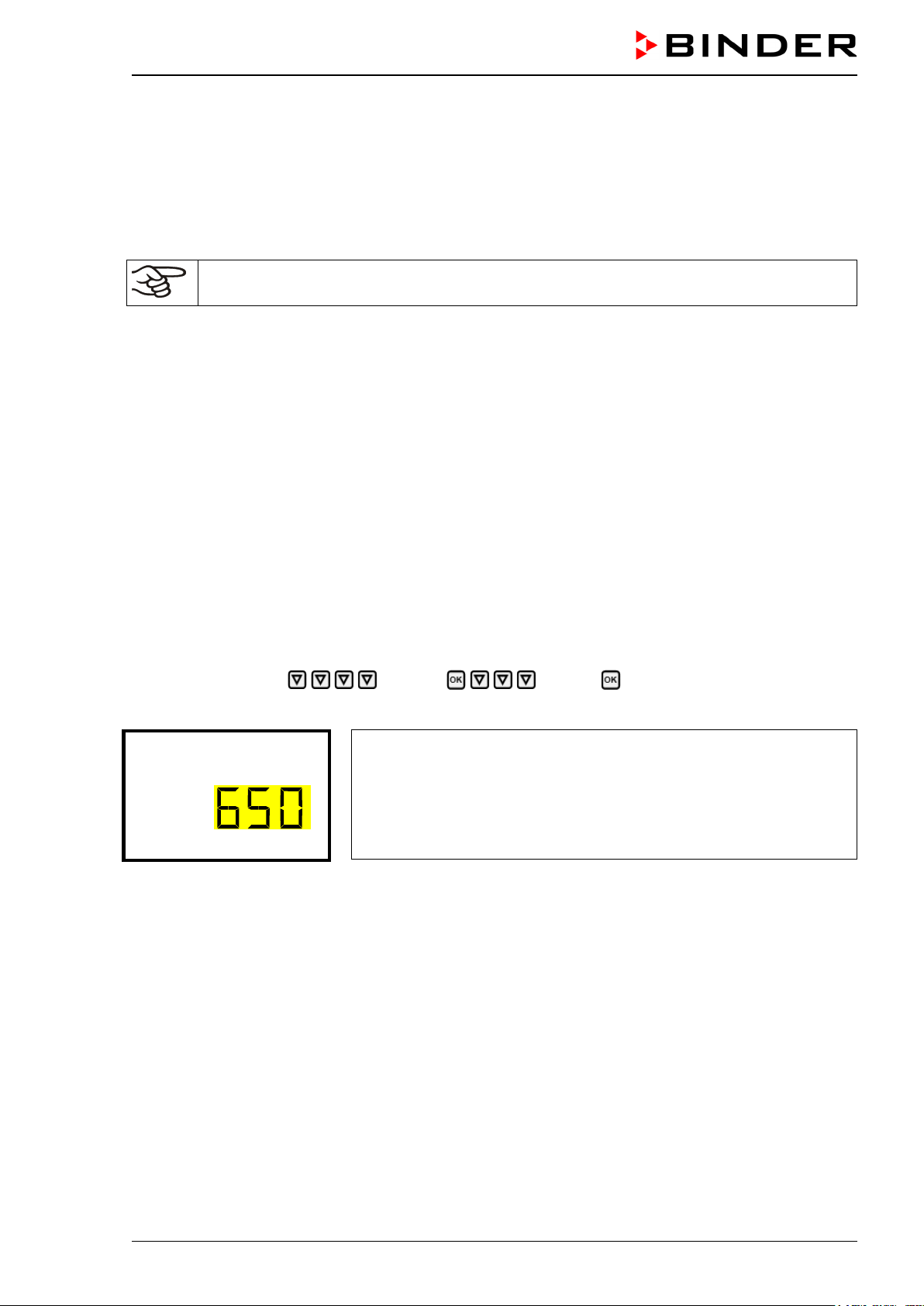
Altitude (m)
• Current time (chap. 12.4), format HH:MM:
Use the arrow buttons to set the hours, continue with the OK button.
Use the arrow buttons to set the minutes, confirm with the OK button
Set the controller to t he de sired tem perature, and CO
set points that sh all be used to operate the cham-
2
ber (chap. 7).
Only insert samples into the chamber when it has reached its stable operating state.
If there is no accordance between the actual and set value shown in the display, proper operation of the chamber is not guaranteed.
Temperature: Equilibration time is approx. 2 hours.
CO
: After approx. 5 minutes, the CO2 concentration equilibrates automatically to the preset value.
2
Instructions when observing leakage of condensate from the CO
sensor s ystem and CO2 fluctua-
2
tion:
In the case of CO
zle of the CO
f luctuations and c oncomitant con densate leak age from the inj ection and suct ion noz-
2
sensor compartment after start-up or when taking the chamber back into service, the
2
chamber should be left to dr y open for at least an hour runni ng at 37 °C with the water pan em pty. This
will result in flush ing the sens or compartm ent and tubing from humid air. Rem oving the co ndensate f rom
the CO
sensor system will ensure a turbulence-free CO2 measurement.
2
6.4 Altitude of the installation site above sea level
After first turning on the incubator, enter t he altitude of the site ab ove sea level into the RD4controller.
This entry serves to correc t the calculation of CO
tial pressure. The setting will remain stored after shutting the power off.
c oncentration in vol.-% from the m easurement of par-
2
Required access level: “Admin”.
Path: Normal display Settings Various Altitude
Press the OK button to enable the setting.
Setting the altitude.
The current setting flashes. Enter the desired altitude. Entry range: 0 m
/ 0 ft up to 2000 m / 6562 ft.
Confirm the entry with the OK button.
With the Back button you can go b ack to the “Various” submenu and, re peatedl y pressing it , to Normal
display.
Unit of altitude
above sea level for entry and displayed value: kilometer [km]
Correlation feet [ft] to kilometer [km]: see chap. 26.5.
CB-S / CB-S-UL (E7) 06/2020 page 39/119
Page 40

Temperature
CO2
7. Temperature and CO2 set-point entry
Required access level: “User”.
Setting ranges Control ranges
Temperature 0 °C / 32 °F up to 50 °C / 122 °F 6 °C / 10.8 °F above ambient up to 50 °C / 122 °F
Humidity 0 vol.-% up to 20 vol.-% 0 vol.-% up to 20 vol.-%
7.1 Temperature set-point entry
Path: Normal display Setpoints Temperature
Press the OK button to enable the setting.
Temperature setting.
The current setting flashes. Enter the desired set-point with the arrow
buttons.
Confirm the entry with the OK button.
With the arrow-down button you can continue with the CO2 set-point entry (chap. 7.2).
With the Back button you can go bac k to the “Setpoints” subm enu and, repeat edly pressing i t, to Nor-
mal display.
When setting a lower temperature set point, in order to save time, we recommend cooling
down the chamber by turning it off and opening the chamber doors.
With safety controller mode “Limit”, adapt the safety controller always when you changed the
temperature set-point. Set the safety controller value by approx. 2 °C above the temperature
set-point (chap. 11.2).
Recommended setting: safety controller mode “Offset” with safety controller value 2 °C.
7.2 CO2 set-point entry
Path: Normal display Setpoints CO2
Press the OK button to enable the setting.
CO
set-point setting
2
The current setting flashes. Enter the desired set-point with the arrow
buttons.
Confirm the entry with the OK button.
With the arrow-up button you can go back to the temperature set-point entry (chap. 7.1)
With the arrow-down button you can now change to the special controller functions setting (chap. 9)
With the Back button you can go bac k to the “Setpoints” subm enu and, repeat edly pressing i t, to Nor-
mal display.
When setting a lower CO
chamber doors for this purpose.
set point, the CO2 gas must be able to escape first. Open the
2
CB-S / CB-S-UL (E7) 06/2020 page 40/119
Page 41

If no CO2 concentration is indicated (display showing “ – – – – ”) the CO2 sensor is not connected.
Note when setting high gas concentrations
Carbon dioxide (CO
and therefore practica lly imperceptible. Any CO
room ventilation or a sui table connec tion t o an ex haust s ystem. W e rec ommend i nstalling a CO
) in high conce ntrations is hazardous to he alth. It is colorless and almost odorless
2
gas that may escape must be safely led out via good
2
warning
2
system.
DANGER
Danger of suffocation and poisoning by high concentration of CO2 (> 4 Vol.-%).
Death by suffocation.
∅ Do NOT set up chambers in non-ventilated recesses.
Ensure technical ventilation measures.
Observe the relevant regulations for handling CO
.
2
If CO2 is released, leave the area und inform the security service or fire department.
8. Placing samples in the incubator
In order to detect pos sible transport dam ages we recommend a 1 or 2 d ays test run at the desired setpoints before placing valuable samples. Then you can load the chamber with the samples.
WARNING: If customer should use a chamber running in non-supervised continuous operation, we strongly recommend in case of inclusion of irrecoverable specimen or samples to
split such specimen or samples and store them in at least two chambers, if this is feasible.
During the equilibrat ion phase of approx. 2 hours af ter turning on the chamber, undef ined temperature
and CO
conditions oc cur within the chamber. During this phase, do not place any sample m aterials in
2
the chamber.
HINWEIS
Danger of undefined temperature and CO2 conditions in the equilibration phase.
Destruction of samples.
Load the chamber only after equilibration of temperature and CO
Do not exceed the maximum load of each shelf and the permitted total load (see chap.26.4).
.
2
CB-S / CB-S-UL (E7) 06/2020 page 41/119
Page 42

Functions on/off
Temp. / CO2
Temp. / CO2
9. Setting special controller functions
In the “Functions on/off” menu you can define the switching state of the special controller functions.
Required access level: “User”.
Path: Normal display Setpoints Functions on/off
The functions are displayed from left to right.
Example: Function 1 “Humidity off” activated = 1000. Function 1 “Humidity off” deactivated = 0000.
Submenu “Functions on/off”.
This view shows the switching states four functions.
“1” = Function activated
“0” = Function deactivated
Press the OK button to ac cess the first individual function. W ith the arrow-down button you can proceed to the subsequent functions.
• Function 1 “Idle mode”: Change to “Idle mode”, chap. 9.1
• Function 2 “CO2 off”: Deactivating CO
control, chap. 9.2
2
• Functions 3 and 4 have no function with this ch amber type.
Press the OK button to enable the setting of the desired function and select the function’s switching state
“1” (function activated) or “0” (function deactivated).
With the Back button you can go bac k to the “Setpoints” submenu and, repeat edly pressing i t, to Nor-
mal display.
In Normal display the acti vated functions are indica ted by an icon showing th e number of the respec tive
function.
Example:
Normal display with activated function 1 “Idle mode”.
9.1 Idle mode
In this operating m ode, temperature and CO2 control ar e deactivated. The actu al values continue to be
displayed in Norm al Display. This operating m ode is switched on or of f via the controller f unction 1 “Idle
mode” (chap. 9). In Normal Display the activated function 1 is indicated by an icon showing the number 1.
CB-S / CB-S-UL (E7) 06/2020 page 42/119
Normal display in “Idle mode” (sample values)
Page 43
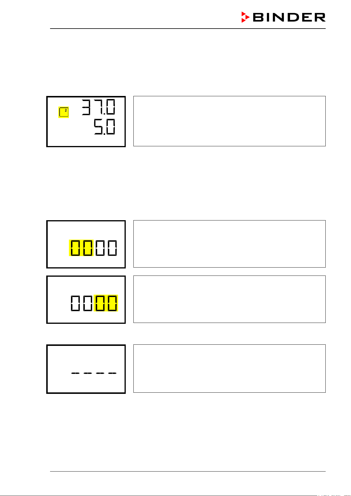
Temp. / CO2
Password
Password
Wrong password
9.2 Deactivated CO2 control
When operating the c hamber without a CO2 gas co nnection, you can deactivate CO2 control with the
function “CO2 off” (chap. 9) to avoid alarms of the CO
no pressure alarm will be emitted.
gas system. No CO2 tolerance range alarm s and
2
The actual CO
value continues to be displayed in No rmal Display. The acti vated function 2 is indicated
2
by an icon showing the number 2.
Normal display with deactivated CO
control (sample values)
2
10. Password
10.1 P assword request
To access menus for which access is restricted, you must enter the corresponding password.
After calling the appropriate menu function with the OK button the password request appears.
Password request.
The left two digits are flashing. Enter the desired numbers with the
arrow buttons.
Confirm the setting with the OK button.
Password request.
The right two digits are flashing. Enter the desired numbers with the
arrow buttons.
Confirm the setting with the OK button.
Upon entering an incorrect password, the information message “Wrong password” is displayed.
Display “Wrong password”.
After 3 seconds the controller changes again to the password entry.
Enter the correct password.
Following correct password entry you can access the desired menu function.
CB-S / CB-S-UL (E7) 06/2020 page 43/119
Page 44

Password User
Password User
Password Admin
Password Admin
10.2 Assign and modify a password
In this menu you can assign and modify the passwords of the “User” and “Admin” access levels.
Required access level: “Admin”.
Keep the password well in mind. There is no access to the corresponding menu functions
without the correct password.
10.2.1 Assign and modify the User password
Path: Normal display Settings Chamber Password User
Press the OK button to enable the setting.
Setting the User password.
The left two digits are flashing. Enter the desired numbers with the
arrow buttons.
Confirm the setting with the OK button.
Setting the User password.
The right two digits are flashing. Enter the desired numbers with the
arrow buttons.
Confirm the setting with the OK button.
With the arrow-down button you can now proceed to enter the Admin password.
With the Back button you can go back to the “Chamber” submenu and, repea tedly pressing it, to Nor-
mal display.
10.2.2 Assign and modify the Admin password
Path: Normal display Settings Chamber Password Admin
Press the OK button to enable the setting.
Setting the Admin password.
The left two digits are flashing. Enter the desired numbers with the
arrow buttons.
Confirm the setting with the OK button.
Setting the Admin password.
The right two digits are flashing. Enter the desired numbers with the
arrow buttons.
Confirm the setting with the OK button.
With the Back button you can go back to the “Chamber” submenu and, repea tedly pressing it, to Nor-
mal display.
CB-S / CB-S-UL (E7) 06/2020 page 44/119
Page 45

11. Temperature safety devices
11.1 Over temperature protective device (class 1)
The CO2 incubator is equipped with one (CB-S-UL) or two (CB-S) internal temperature safety devices
class 1 acc. to DIN 12880:2007. They serve t o protect the chamber and prevent dangerous condi tions
caused by major defects.
If one of the over temperature protective devices permanently turns off the chamber, the user cannot
restart the device again. The protective cut-off devices are located internally. Only a service specialist can
replace them. Therefore, please contact an authorized service provider or BINDER Service.
11.2 Overtemperature safety controller class 3.1
The chambers ar e regularly equipped with an elec tronic overtemperature saf ety controller (temperature
safety device clas s 3.1 acc ording t o DIN 12880:2007) . If an error occ urs, t he safet y controller perfor ms a
regulatory function.
Please observe the DGUV guidelin es 213-850 on s afe working in laboratories, issued by the emplo yers’
liability insurance association (for Germany).
The overtemperatur e safety controller serves to prot ect the chamber, its environ ment and the contents
from exceeding the m aximum permissible temperature. In the case of an error, it limits the tem perature
inside the cham ber to the enter ed saf et y contr oller value. T his cond ition (state of alarm ) is indicat ed v isually and additionall y with an audi bl e al ert if the bu zze r i s enabl ed (c hap. 15.3). The alarm pers ist s until the
chamber cools down below the configured safety controller value and the alarm is reset on the controller.
Check the setting regularly and adjust it following changes of the temperature set-point or
charge.
The safety controller only activates after the set-point has been reached once.
You can set the safety controller mode to “Limit” or “Offset”.
• Limit: Limit value, absolute maximum permitted temperature value
This setting off ers high safety as a defined tem perature limit will not be exceeded. It is important to
adapt the safety contr oller value after each modification of the tem perature set-point. Other wise, the
limit could be too high to ensure ef ficient protectio n, or , in the o pposite c ase, it c ould pre vent the controller from reaching an entered set-point outside the limit range.
• Offset: Offset value, maximum overtem per ature a bo ve any active temperatur e s et po int . T he res u lti ng
maximum temperature changes internally and automatically with every temperature set-point change.
Example:
Desired temperature value: 37 °C, desired safety controller value: 39 °C.
Possible settings for this example:
Temperature set point Safety controller mode Safety controller value
Limit Limit value 39 °C
37 °C
Offset Offset value 2 °C
Factory setting: Safety controller mode “Offset” with safety controller value 2 °C.
The settings of the safety controller are inactive during sterilization (chap. 23). They become
functional again following abortion of the sterilization and/or the restart of the chamber at the
main power switch.
CB-S / CB-S-UL (E7) 06/2020 page 45/119
Page 46
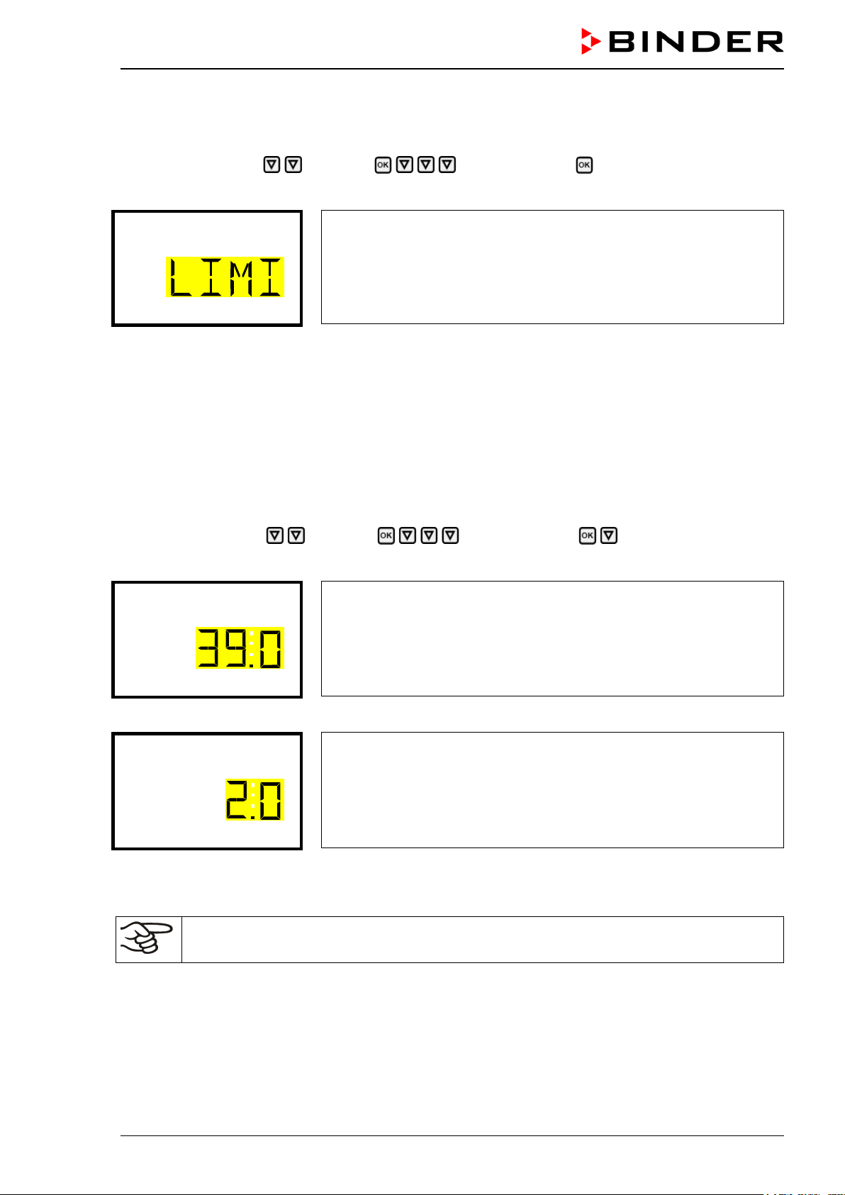
Mode
Limit
Offset
11.2.1 Setting the safety controller mode
Required access level: “User”.
Path: Normal display Setpoints Safety controller Mode
Press the OK button to enable the setting.
Setting the safety controller mode
The current setting flashes. Use the arrow buttons to select between
LIMI (Limit) and OFFS (Offset).
Confirm the setting with the OK button.
With the arrow-down button you proceed to setting the safety controller value (chap. 11.2.2)
With the Back button you can go back to the “Safety controller” submenu and, repeatedly pressing it, to
Normal display.
11.2.2 Setting the safety controller value
Required access level: “User”.
The desired safety contro ller mode m ust be selected f irst (c hap. 11.2.1). Depending on th e mode s etting,
one of the following setting menus will appear.
Path: Normal display Setpoints Safety controller Limit or Offset
Press the OK button to enable the setting.
Setting the safety controller value with “Limit” safety controller mode.
The current value flashes. Enter the desired limit value with the arrow
buttons.
Confirm the entry with the OK button.
or
Setting the safety controller value with “Offset” safety controller mode
The current value flashes. Enter the desired offset value with the arrow
buttons.
Confirm the entry with the OK button.
With the Back button you can go back to the “Safety controller” submenu and, repeatedly pressing it, to
Normal display.
Regularly check the settings of the safety controller mode and value.
Set the safety controller value by approx. 2 °C above the desired temperature set-point.
CB-S / CB-S-UL (E7) 06/2020 page 46/119
Page 47

Safety controller
11.2.3 Message and measures in the state of alarm
The state of alarm is indica ted visuall y in Normal display. If the b uzzer is enab led ( chap. 15.3) there is an
additional audible alert. The heating turns off. As soon as the inner chamber temperature has cooled
down below the safety controller value, the heating is released and temperature control continues.
In Normal displa y a text message indicates the alarm c ause. The “collective alarm” icon flashes. If the
audible arm is activated, the buzzer sounds. Press the OK button to mute the buzzer.
The alarm mess age “ Saf ety controller” and the “ Co ll ectiv e a larm” icon are displayed on the controller u nti l
you press the OK button on the controller and the inner cham ber temperature has co oled down below
the safety controller value.
• If the inner chamber temperature has already cooled down below the safety controller value when
pressing the OK button, the alarm message “Safety controller” and the “Collective alar m” icon are reset together with the buzzer.
• If the stat e of alar m is still activ e when pr essing the OK button, i. e. the in ner cha m ber temperatur e is
still above the safety controller value, first only the buzzer is reset. The alarm message “Saf et y contro ller” and the “Collective alarm ” icon will disappear as soon as the inn er chamber tem perature falls below the safety controller value.
• The alarm remains active until it is acknowledged on the controller and the inner temperature falls
below the entered safety controller setpoint. Then the heating is released again.
Normal display showing safety controller alarm (sample values)
Note:
When the safety controller class 3.1 had been activated you should disconnect the cham ber from the
power supply and have an expert examine and rectify the cause of the fault.
11.2.4 Function check
Check the safety contr oller at ap propri ate int ervals for i ts f unctiona lity. It is recom m ended that the authorized operating personnel should perform such a check, e.g., before starting a longer work procedure.
CB-S / CB-S-UL (E7) 06/2020 page 47/119
Page 48

Language
Temperature unit
12. General controller set ti ngs
The general settings can be ac cessed in the “Settings” submenu, which is avail able for users with “Service” or “Admin” authori zation leve l. It serves to enter date and tim e, selec t the la nguage f or the cont roller
menus and the desired temperature unit and to configure the controller’s communication functions.
The display of some network settings is available for all users in the “Chamber info” menu.
12.1 S electing the controller’s menu language
The RD4 controller c ommunicates by a menu gui de using re al words in G erman, En glish, Frenc h, Spanish, and Italian languages.
Required access level: “Admin”. Following start-up of the chamber (chap. 6.3), it is “User”.
Path: Normal display Settings Chamber Language*
* Following st art-up of the c ham ber: Sprach e / Lang uag e / Langue / Idioma / Lingua, depending on t he
language selected before turning off the chamber
Press the OK button to enable the setting.
Setting the menu language (example: English).
The current setting flashes. Use the arrow buttons to select the desired
language.
Confirm the entry with the OK button.
With the arrow-down button (twice) you can now change to the temperature unit setting.
With the Back button you can go back to the “Chamber” submenu and, repea tedly pressing it, to Nor-
mal display.
12.2 S electing the temperature unit
Required access level: “Admin”. Following start-up of the chamber (chap. 6.3), it is “User”.
Path: Normal display Settings Chamber Temperature unit
Press the OK button to enable the setting.
Setting the temperature unit
The current setting flashes. Use the arrow buttons to select between
°C (degrees Celsius) and °F (degrees Fahrenheit).
Confirm the entry with the OK button.
You can change the temperature unit between °C and °F.
If the unit is changed, all values are converted accordingly
With the Back button you can go back to the “Chamber” submenu and, repea tedly pressing it, to Nor-
mal display.
CB-S / CB-S-UL (E7) 06/2020 page 48/119
C = degree Celsius
F= degree Fahrenheit
0 °C = 31°F
100 °C = 212°F
Conversion:
[value in °F] = [value in °C] ∗ 1,8 + 32
Page 49

Date
Date
Date
Date
12.3 Setting the current date
Required access level: “Admin”. Following start-up of the chamber (chap. 6.3), it is “User”.
Path: Normal display Settings Chamber Date
Press the OK button to enable the setting.
Setting the date: day
The current setting flashes. Enter the current day with the arrow but-
tons.
Confirm the entry with the OK button.
Setting the date: month
The current setting flashes. Enter the current month with the arrow
buttons.
Confirm the entry with the OK button.
Setting the date: year
The left two digits are flashing. Enter the first two digits of the current
year with the arrow buttons.
Confirm the entry with the OK button.
Setting the date: year
The right two digits are flashing. Enter the last two digits of the current
year with the arrow buttons.
Confirm the entry with the OK button.
With the arrow-down button you can now change to setting the current time.
With the Back button you can go back to the “Chamber” submenu and, repea tedly pressing it, to Nor-
mal display.
CB-S / CB-S-UL (E7) 06/2020 page 49/119
Page 50

Time
Time
Language sel. at restar
12.4 Setting the current time
Required access level: “Admin”. Following start-up of the chamber (chap. 6.3), it is “User”.
Path: Normal display Settings Chamber Time
Press the OK button to enable the setting.
Setting the time: hours
The current setting flashes. Enter the current hour with the arrow but-
tons.
Confirm the entry with the OK button.
Setting the time: minutes
The current setting flashes. Enter the current minutes with the arrow
buttons.
Confirm the entry with the OK button.
With the Back button you can go back to the “Chamber” submenu and, repea tedly pressing it, to Nor-
mal display.
12.5 Function “Language selection at restart”
If the function “Langu age selection at restart” is activated, menu language, date, time, and temper ature
unit are checked with every startup of the chamber. At this occasion it is also possible to modify them with
“User” access level.
Required access level: “Admin”.
Path: Normal display Settings Chamber Language selection at restart
Press the OK button to enable the setting.
Function “Language selection at restart”
The current setting flashes. Use the arrow buttons to select between
ON and OFF.
Confirm the setting with the OK button.
With the arrow-down button you can now change to the next parameter (chamber address).
With the Back button you can go back to the “Chamber” submenu and, repea tedly pressing it, to Nor-
mal display.
CB-S / CB-S-UL (E7) 06/2020 page 50/119
Page 51

Chamber address
Brightness
12.6 Setting the chamber address
This setting is requir ed for the comm unication with the BINDER APT-COM™ 4 Multi Management Sof tware. The chamber address settings in the chamber controller and in the software must be identical.
Required access level: “Admin”.
Path: Normal display Settings Chamber Chamb er add res s
Press the OK button to enable the setting.
Setting the chamber address
The current setting flashes. Enter the desired address with the arrow
buttons. Setting range: 1 up to 254
Confirm the entry with the OK button.
With the arrow-down button you can now change to the next parameter (display brightness).
With the Back button you can go back to the “Chamber” submenu and, repea tedly pressing it, to Nor-
mal display.
12.7 Display brightness
Required access level: “Admin”.
Path: Normal display Settings Chamber Brightness
Press the OK button to enable the setting.
Setting the display brightness
The current setting flashes. Enter the desired value with the arrow but-
tons. Setting range: 10% up to 100%
Confirm the entry with the OK button.
With the arrow-down button you can now change to the next parameter (audible alarm, chap. 15.3).
With the Back button you can go back to the “Chamber” submenu and, repea tedly pressing it, to Nor-
mal display.
CB-S / CB-S-UL (E7) 06/2020 page 51/119
Page 52

Range alarm delay (mi
Temperature range
13. Tolerance range settings
In this menu you can define for temperature and CO2 the deviation between the actual value and setpoint,
which that shall ca use a tolerance range alarm . The entered value defines the limit of permitted deviations from the set-point (exceeding and falling below). Reaching this limit triggers tolerance alarm.
In addition you can specify a delay time for this alarm.
If there are an y ac tu al v alu es ou ts ide t he to ler anc e ra nge, after the configured alarm delay t ime the alarm
message “Temper ature range” and / or “CO2 range” is displayed i n Normal display (chap. 15.1). If the
alarm buzzer is activated (chap. 15.3) there is an audible alert.
This function only activates after the set-point has been reached once.
Required access level: “Admin”.
13.1 Setting the delay time for tolerance range alarm
Path: Normal display Settings Various Range alarm delay (min)
Press the OK button to enable the setting.
Setting the tolerance range alarm delay.
The current setting flashes. Use the arrow buttons to enter the de-
sired time after which the range alarm shall be triggered. Entry range: 1
up to 120 minutes.
Confirm the entry with the OK button.
With the arrow-down button you can now change to the temperature tolerance range setting.
With the Back button you can go back to the “ Various” submenu and, repeated ly press ing it, to Normal
display.
13.2 S etting the temperature tolerance range
Path: Normal display Settings Various Temperature range
Press the OK button to enable the setting.
With the arrow-up button you can go back to the tolerance range alarm delay setting.
With the arrow-down button you can now change to the CO
With the Back button you can go back to the “ Various” submenu and, repeated ly press ing it, to Normal
display.
Setting the temperature tolerance range
The current setting flashes. Enter the desired temperature range with
the arrow buttons. Entry range: 1.0 °C up to 10.0 °C
Confirm the entry with the OK button.
tolerance range setting.
2
CB-S / CB-S-UL (E7) 06/2020 page 52/119
Page 53

CO2 range
Door alarm delay (min)
13.3 Setting the CO2 tolerance range
Path: Normal display Settings Various C O2 ran ge
Press the OK button to enable the setting.
Setting the CO
The current setting flashes. Enter the desired CO
tolerance range
2
row buttons. Entry range: 1.0 vol.-% up to 10.0 vol.-%
Confirm the entry with the OK button.
range with the ar-
2
With the arrow-up button you can go back to the temperature range setting
With the arrow-down button you can now change to the door open alarm delay setting.
With the Back button you can go back to the “ Various” submenu and, repeated ly press ing it, to Normal
display.
13.4 S etting the delay time for door open alarm
Path: Normal display Settings Various Doo r alarm d ela y
(min)
Press the OK button to enable the setting.
Setting the door open alarm delay.
The current setting flashes. Use the arrow buttons to enter the de-
sired time after which the door alarm shall be triggered. Entry range: 1
up to 120 minutes.
Confirm the entry with the OK button.
With the arrow-up button you can go back to the CO2 tolerance range setting
With the arrow-down button you can now change to the humidity control setting.
With the Back button you can go back to the “ Various” submenu and, repeated ly press ing it, to Normal
display.
CB-S / CB-S-UL (E7) 06/2020 page 53/119
Page 54

Humidity control
Doortemp. offset
14. Chamber settings (for e x per ienc e d users only)
14.1 Setting the humidity control
The humidifying system provides a maximum humidity of up to 95 % r.h. in the inner chamber, which
remains condensation-free. This performance ass umes an average am bient temperature of +22 °C +/- 3
°C / 71.6 °F +/- 5.4 °F and a working temperature in the inner chamber of 37 °C / 98.6 °F.
Depending on the inst a llati on s it e a nd ambient temperature you can increase or d ec reas e the humidit y by
up to +/- 5 % r.h. if required. Factory setting: 0 % r.h.
If the ambient temperature deviates by more than +/- 5 °C from the values recommended by
the manufacturer, the conditions for maximum air humidity with condensation-free inn er
chamber are no longer guaranteed. Contact BINDER Service for assistance.
Path: Normal display Settings Various Humidit y co n-
trol
Press the OK button to enable the setting.
Setting the humidity control
The current setting flashes. Enter the desired value with the arrow
buttons. Entry range: -5 % r.h. up to +5 % r.h.
Confirm the entry with the OK button.
With the arrow-up button you can change to the door open alarm delay setting (chap. 13.4).
With the arrow-down button you can now change to the door heating offset setting.
With the Back button you can go back to the “ Various” submenu and, repeated ly press ing it, to Normal
display.
14.2 Setting the door heating offset
In unfavorable ambient conditions, condensation may occur in the door area. To avoid this, an Offset
value for the door heating can be set. Factory setting: 3.0 °C.
If the ambient temperature deviates by more than +/- 5 °C from the values recommended by
the manufacturer, the conditions for maximum air humidity with condensation-free inn er
chamber are no longer guaranteed. Contact BINDER Service for assistance.
Path: Normal display Settings Various Doortemp.
offset
Press the OK button to enable the setting.
With the arrow-up button you can go back to the humidity control setting.
With the Back button you can go back to the “ Various” submenu and, repeated ly press ing it, to Normal
display.
CB-S / CB-S-UL (E7) 06/2020 page 54/119
Setting the door temperature offset.
The current setting flashes. Enter the desired value with the arrow
buttons. Entry range: -5.0 °C up to +5.0 °C.
Confirm the entry with the OK button.
Page 55

Factor humid. recover
In Normal display a text message indicates the alarm cause. The “collective alarm” icon flashes. If
the audible arm is activated, the buzzer sounds.
Safety controller
14.3 Adjusting the heating power – for BINDER Service only
Depending on the dur ation of the door o pening, a heat ing power f actor f or humidit y recover y time c an be
adapted. Factory setting: 1 2.0.
This setting is intended for BINDER Service only!
Path: Normal display Settings Various Factor
humid. recovery
Press the OK button to enable the setting.
Setting the heating po wer factor for humidity recovery time.
The current setting flashes. Enter the desired factor with the arrow
buttons. Entry range: 0.0 to 100.0.
Confirm the entry with the OK button.
With the arrow-up button you can go back to the door heating offset setting.
With the Back button you can go back to the “ Various” submenu and, repeated ly press ing it, to Normal
display.
15. Notification and alarm func t ions
15.1 Alarm messages
WARNING: If customer should use a chamber running in non-supervised continuous operation, we strongly recommend in case of inclusion of irrecoverable specimen or samples to
split such specimen or samples and store them in at least two chambers, if this is feasible.
In the event of equipm ent failures, or when t he temperature and / or CO2 deviate from t he set tolerance
range limits, optical and po s s ibly acous tic a larm messages are given out via the c ontr ol ler. A ze ro-voltage
relay alarm output (9) (chap. 15.5) permits transmission of the alarm e.g., to a central monitoring system.
The alarm messages door open and leaving the tolerance rang e are emitted after a configura ble delay
(chap. 13), the others immediately when the fault occurs. The tolerance range alarms are suppressed
after opening the cham ber door or turning on the chamber until the corresponding s etpoint is reached,
and then for the selected delay time.
If more than one alarm signal is sent simultaneously, they are displayed in a cycle.
Press the OK button to confirm the alarm and m ute the buzzer. If the a larm cause is s till valid, the “col-
lective alarm” icon is lit.
Alarm indication (example: safety controller alarm)
CB-S / CB-S-UL (E7) 06/2020 page 55/119
Page 56

Moment of alarm message and
alarm relay output
Alarm messages overview:
Condition Icon Alarm message
switching the zero-voltage
after configurable time
Chamber door open
Setpoint of the safety controller
class 3.1 exceeded
Tolerance range alarm: actual
temperature value exceeding
the tolerance range)
Tolerance range alarm: actual
value exceeding the tol-
CO
2
erance range
“Door open”
(chap. 13.4).
Factory setting: 1 minute
“Safety controller” immediately
after configurable time
“Temperature range”
(chap. 13.1)
Factory setting: 10 minutes
after configurable time
“CO2 range”
(chap. 13.1)
Factory setting: 10 minutes
CO2 pressure too low “CO2 pressure” immediately
Inner temperature sensor de-
fective. Control continues using the safety controller temperature sensor.
Actual temperature value
display shows
“ – – – – ”
“Inner temp. sensor”
immediately
Messages alternating:
Failure of safety controller
temperature sensor
“Safety controller” and
“Safety control sensor”
immediately
Actual temperature value
display shows
Failure of inner temperature
sensor and safety controller
temperature sensor
“Inner temp. sensor”, “Safety
“ – – – – “
Messages alternating:
immediately
controller”, and “Safety con-
trol sensor”
Failure of temperature sensor
for door heating
Failure of CO2 sensor
“Door heating sensor” immediately
Actual CO
display shows
“ – – – – ”
value
2
immediately
“CO2 sensor defective” after 1 minute
CO2 sensor not connected
Actual CO
display shows
value
2
immediately
“ – – – – ”
Sterilization terminated prematurely after less than 6 hours:
“Sterilization failed” immediately
Ineffective sterilization
Press the OK button to confirm the alarm.
• Confirm ation while the state of alarm persists : Only the buzzer is muted. The visual alarm message
continues to be displayed until the alarm condition is removed. Then it is reset automatically.
• Confirmation after the alarm has ended: The buzzer and the visual alarm message are rest together.
CB-S / CB-S-UL (E7) 06/2020 page 56/119
When operating the chamber without CO2 gas connection, turn off CO2 control (function
“CO2 off”, chap. 9) in order t o avoid alarms of the CO
gas system.
2
Page 57

Sterilization
Moment of information
message
15.2 I nform ation messages
Information messages provide information about the settings made or the current controller condition.
In Normal display a text message indicates the condition. The “Information” icon is lit.
Information message (example: sterilization running)
Information messages overview:
Condition Icon Information message
Trying to start sterilization cycle
while the CO
sensor still
2
“CO2 sensor plugged-in” Sterilization start
plugged-in
Sterilization is running
Sterilization successfully completed
“Sterilization” During sterilization
“Sterilization success”
Recommended maintenance
interval (one year of operation)
“Service due!”
is over.
Press the OK button to confirm the information message.
After 6 hours
of sterilization cycle
Each week of operation after
maintenance interval is over .
CB-S / CB-S-UL (E7) 06/2020 page 57/119
Page 58

Audible alarm
15.3 Activating / deactivating the audible alarm (alarm buzzer)
Path: Normal display Settings Chamber Audible alarm
Press the OK button to enable the setting.
Setting the audible alarm.
The current setting flashes. Use the arrow buttons to select between
ON and OFF.
Confirm the setting with the OK button.
With the Back button you can go back to the “Chamber” submenu and, repea tedly pressing it, to Nor-
mal display.
15.4 Measures in case of alarm
Only qualified service personnel authorized by BINDER must perform repair.
Repaired chambers must comply with the BINDER quality standards.
15.4.1 Door open alarm
The open and clos ed positi on of the c ham ber door is control led via th e door co ntact s witch. If the door is
open, the temperature and CO
When the door is opened t he alarm occur s after an adjustabl e delay time ( chap. 13.4). Factory setting: 1
minute.
controls turn off.
2
• Alarm message “Door open”, “collective alarm” icon
• Audible alarm: buzzer
• Switching the zero-voltage relay alarm output
Actions:
• Close the outer door.
• Use the OK button to turn off the buzzer even when the door is open.
• The alarm message is cancelled.
• The zero-voltage relay alarm output switches off.
15.4.2 Safety controller temperature alarm
The set temperature value (set point type “Limit” or “Offset”) was exceeded.
• Immediate alarm
• Alarm message “Safety controller”, “collective alarm” icon
• Audible alarm: buzzer
• Switching the zero-voltage relay alarm output.
CB-S / CB-S-UL (E7) 06/2020 page 58/119
Page 59

Actions:
• Check whether the outer door was open f or a long time or is not c losed properly. Close the door if
necessary. With open door there can be addition al doo r open alarm.
• Check the s etting of the safety control ler (chap. 11.2). The lim it temperature should be at least 2 °C
above the temperatur e s et poi nt; th e off s et temperature should be ≥ 2 °C. If necess ar y, adjust the relevant value.
• Check whether samples were inserted into the chamber that produce heat.
• Check the am bient condit ions. The am bient temper ature mus t be at least b y 6 °C / 10.8 °F below the
temperature set point of the chamber. Protect the chamber from direct sunlight. Ensure sufficient ventilation around the installation location to prevent any buildup of heat in the chamber.
• Check whether the steri lization c ycle was term inate d prematurely and the cham ber has not yet cooled
down.
• If these points do not reveal the source of the fault, it may be that the chamber is faulty. Please contact
BINDER Service.
15.4.3 Temperature tolerance range alarm (overtemperature / too low temperature)
The tolerance range alarm becomes valid only after the setpoint has been reached.
When the actual value leaves the tolera nce range the alarm occ urs after an adjus table dela y time (chap.
13.1). Factory setting: 10 minutes.
• Alarm message “Temperature range”, “col lecti ve al arm” icon
• Audible alarm: buzzer
• Switching the zero-voltage relay alarm output
Actions:
• Factory sett ing for the temper ature tolerance ran ge is +/- 1.0 K. Mo dify the value if necessary (chap.
13.2).
• Use the displ ayed actual temperature value to verify in whether the tolerance range has been exceed-
ed (too warm) or fallen below (too cold).
Low temperature alarm:
• Check whether the outer door was open f or a long time or is not c losed properly. Close the door if
necessary. With open door there can be ad dit ion al doo r open alar m.
• Check the door's seals for any damage. Replace any damaged seals.
Overtemperature alarm:
• Check whether samples were insert ed into the chamber th at produce heat. Res et the alarm with the
OK button.
• Check the am bient condit ions. The ambient tem perature m ust be at leas t by 6 °C / 10.8 °F below the
temperature set point of the chamber. Protect the chamber from direct sunlight. Ensure sufficient ventilation around the installation location to prevent any buildup of heat in the chamber.
• If these points do not reveal the source of the fault, it may be that the chamber is faulty. Please contact
BINDER Service.
• To decrease the temperature, proceed as foll ows: Turn off the cham ber. Open both cham ber do ors f or
approx. 5 minutes. Turn on the cham ber again. You c an restart normal operatio n as soon as the requested values have equilibrated.
If the same alarm recurs, please contact BINDER Service.
CB-S / CB-S-UL (E7) 06/2020 page 59/119
Page 60

15.4.4 CO2 tolerance range alarm (CO2 over/under concentration)
If CO2 control has been deactivated (chap. 9.2), no alarms of the CO2 gas system will be emitted.
The tolerance range alarm becomes valid only after the setpoint has been reached.
When the actual value leaves the tolera nce range the alarm occ urs after an adjus table dela y time (chap.
13.1). Factory setting: 10 minutes.
• Alarm message “CO2 range”, “collective alarm” icon
• Audible alarm: buzzer
• Switching the zero-voltage relay alarm output
Actions:
• Factory setting for the CO
• Use the disp layed actual CO
tolerance range is +/- 1.0 vol.-%. Modify the value if necessary (chap. 13.3)
2
value to verify in whether the tolerance rang e has been exceeded or
2
fallen below.
under concentration alarm:
CO
2
• Check whether the outer door was open f or a long time or is not c losed properly. Close the door if
necessary. With open door there can be addition al doo r open alarm.
• Check the door's seals for any damage. Replace any damaged seals.
• If these points do not reveal the source of the fault, it may be that the chamber is faulty. Please contact
BINDER Service.
CO
over concentration alarm:
2
• Open both c hamber doors for approx. 3 0 seconds. Respect the prec autions when working with CO
gas (chap. 1.8).
• Normal operation can be restarted, as soon as the requested values have been readjusted.
• Reset the alarm message.
If the same alarm recurs, please contact BINDER Service.
15.4.5 CO2 pressure alarm
2
If CO2 control has been deactivated (chap. 9.2), no alarms of the CO2 gas system will be
emitted.
The CO2 primary pressure at the intake valve is less than 0.3 bar / 4.4 psi below the ambient air pressure.
The alarm displa ys show a pressure drop of CO
gas cylinder is open. CO
connection pressure is too low.
2
admission below 0.3 bar / 4.4 psi. Check whether the
2
The alarm occurs immediately.
• Alarm message “CO2 pressure”, “collective alarm” icon.
• Audible alarm : buzzer
• Switching the zero-voltage relay alarm output
CB-S / CB-S-UL (E7) 06/2020 page 60/119
Page 61

NOTICE
Actions:
• Check that you have set the press ure on the pressur e reducer at 2.0 bar / 29 psi above the am bient
air pressure, and that all the valves are open for the gas supply.
• Where the CO
. If necessary, replace the gas cylinder. Observe the precautions when h andling gases and the
CO
2
supply is a pressurized gas cylinder, check that the cylinder still contains sufficient
2
correct outlet pressure (chap. 4.4).
• When using central CO
supply, check whether the primary pressure is high enough.
2
• Check that the gas tube has no damage, kinks, blockages or soiling.
• Check when the gas filter was last replaced. Rep lace the gas filter e very year to avoid it blocking. A
qualified service engineer should replace the gas filter.
• If these points do not reveal the source of the fault, it may be that the chamber is faulty. Please contact
BINDER Service.
The outlet pressure of the gas cylinder must be 2.0 bar / 29 psi above the ambient pressure.
Danger of damage by excessive outlet pressure > 2.5 bar / 36 psi.
Damage to the chamber.
∅ The outlet pressure must NOT exceed the indicated value of 2.5 bar / 36 psi.
Before connecting, check the outlet pressure on the pressure reducer of the cylinder.
Adjust the outlet pressure to 2.0 bar / 29 psi above the ambient pressure.
The recovery times of the gas c oncentratio ns inside the cham ber follo wing the d oor being op ened, which
are indicated in the tech nical data (chap. 26.4), refer to a c onnection pressure of 2.0 bar / 29 psi. Decreasing supply pressur e down to the alarm point of 0.3 bar / 4.4 psi results in lon ger recovery times.
Check the pressure disp lays of your gas suppl y. If very short recovery tim es are required or the door is
opened frequently, re place the gas cylinders prom ptly when the pressure decr eases below 2.0 bar / 29
psi.
15.4.6 Power failure alarm
• No alarm message (display is off)
• Audible alarm (buzzer): immediately
• Switching the zero-voltage relay alarm output.
WARNING: If customer should use a chamber running in non-supervised continuous operation, we strongly recommend in case of inclusion of irrecoverable specimen or samples to
split such specimen or samples and store them in at least two chambers, if this is feasible.
CB-S / CB-S-UL (E7) 06/2020 page 61/119
Page 62

15.4.7 Alarms referring to temperature sensor failures
The alarms occur immediately.
• Alarm messages corresponding to the individual alarm cause, “collective alarm” icon
• Audible alarm : buzzer (intermittent sound)
• Switching the zero-voltage relay alarm output
• A sensor fault alarm displ ay tak es priority over all other operational displays and alarm s ignals on the
controller.
Actions:
• Turn off the chamber.
• If necessary, clean and disinfect the chamber. Automatic sterilization is not possible with this fault.
• Please contact BINDER Service.
Failure of inner temperature sensor
• Actual temperature value display shows “ – – – – ”
• Alarm message “Inner temp. sensor”
Temperature control continues using the safety controller temperature sensor.
Failure of safety controller temperature sensor
• Alarm messages “Safety controller” and “Safety control sensor” alternating, “collective alarm” icon
All heating elem ents turn off.
Failure of inner temperature sensor and safety controller temperature sensor
• Actual temperature value display shows “ – – – – ”
• Alarm m ess ages “Inner te mp. s ensor”, “Saf ety controller”, and “Safety control se nsor” alternating “col-
lective alarm” icon
All heating elements turn off.
Failure of temperature sensor for door heating
• Alarm message “Door heating sensor”, “collective alarm” icon
The door heating turns off.
CB-S / CB-S-UL (E7) 06/2020 page 62/119
Page 63

15.4.8 Alarms referring to CO2 sensor failure
If CO2 control has been deactivated (chap. 9.2), no alarms of the CO2 gas system will be
emitted.
The alarms occur immediately.
Failure of CO
sensor
2
• Actual CO2 value display shows “ – – – – ”
• Alarm message “CO2 sensor defective”, “collective alarm” icon
Actions:
• Turn off the chamber.
• Remove the sensor (chap. 4.2), replace it if necess ar y.
• If necessary, clean, disinfect and sterilize the chamber before restarting it
• Please contact BINDER Service.
CO
sensor not connected
2
• Actual CO2 value display shows “ – – – – ”
Actions:
• Turn off the chamber.
• Connect the sensor (chap. 4.2.1)
15.4.9 Alarm on ineffective sterilization
The sterilization cycle was terminated prematurely after less than 6 hours (chap. 23.4.1)
• Alarm message “Sterilization failed”, “collective alarm” icon
Actions:
• Repeat the sterilization, if necessary (chap. 23.3).
CB-S / CB-S-UL (E7) 06/2020 page 63/119
Page 64

15.5 Zero-voltage relay alarm output
Collective alarm output via the zero-voltage relay alarm contact
The chamber is equipped a t the r ear with a zero-voltage relay output (13) f or temperature and CO
, which
2
permits the transm ission of alarms to an external monitor ing system in order to monitor a nd record the
alarm signals. A DIN socket (13) serves to establish this connection.
The zero-voltage relay alarm output switches for all alarm instances and in case of a power failure.
Depending on the alarm cause, the state of alarm is triggered immediately or after an adjustable time
(chap. 15.1). W ith the state of alarm , the “collective alarm” icon flashes on the contr oller display, a t ext
message indicates the alar m cause, and the buzzer sounds if the ac oust ic alarm has been ac tivated. The
zero-voltage relay alarm contact switch es withou t an y dela y.
C = Pin 1 (Pole)
NC = Pin 2 (Break relay)
NO = Pin 3 (Make contact)
ALARME
Figure 15: Zero-voltage contacts circuit diagram and pin allocation of DIN socket (13)
In case of no alarm, contact 1 (C) closes with contact 3 (NO).
Closing contact 1 (C) with contact 2 (NC) switches the zero-voltage relay alarm output
Maximum loading capacity of the switching contacts: 24V AC/DC – 2.5 Amp.
DANGER
Electrical hazard through overload of switching contacts.
Deadly electric shock. Damage to switching c o ntacts and connection socket.
∅ Do NOT exceed the maximum switching load of 24V AC/DC – 2.5A.
∅ Do NOT connect any devices with a higher loading capacity.
The alarm mess age on the controller disp lay remains displayed during transmission of an alarm via the
zero-voltage rel ay alar m output. As soon as the c ause of the al arm is r ectified, or the a larm mess age has
been reset, the alarm transmission via the zero-voltage relay outputs is reset together with the alarm
message on the controller display.
In case of power failur e, transmission of the alar m via zero-voltage rela y outputs remains active for the
duration of the po wer failur e. When power su pply retu rns, contact 1 (C ) closes automatically wit h contact
3 (NO).
Connection to an external monitoring system
To ensure short-circuit-proof alarm m onitoring th at wil l trigger t he alar m when the chamber connection to
an external alarm m onitor is interrupted, connect the external alarm m onitor in g system to the chamber via
the contacts 1 (C) and 3 (NO). In this case, power failure will also trigger the alarm.
CB-S / CB-S-UL (E7) 06/2020 page 64/119
Page 65

MAC address
00:00:00:00:00:00
IP address
0.0.0.0
16. Ethernet network settings
The settings of the “Ethernet” submenu are used f or networking chambers with an Etherne t interface,
e.g. to connect them with BINDER’s APT-COM™ 4 Multi Management Software (option, chap. 20.4).
16.1 S howing the network settings
Required access level: “User”.
The “Ethernet” submenu offers to subsequently or individually access the following information:
• MAC address
• IP address
• Subnet mask
• Standard gateway
• DNS server address
• DNS chamber name
16.1.1 Showing the chamber‘s MAC address
Path: Normal display Chamber info Ethernet MAC address
Display of the MAC address (example)
Toggle forth and back with the Back
button and the OK button.
With the arrow-down button you can now change to the next parameter (IP address).
With the Back button you can go bac k to the “Ethernet” submenu and, repeatedly pressing it, to Normal
display.
16.1.2 Showing the IP address
Path: Normal display Chamber info Ethernet IP address
Display of the IP address (example)
Toggle forth and back with the Back
button and the OK button.
With the arrow-down button you can now change to the next parameter (subnet mask).
With the Back button you can go bac k to the “Ethernet” submenu and, repeatedly pressing it, to Normal
display.
CB-S / CB-S-UL (E7) 06/2020 page 65/119
Page 66

Subnet mask
0.0.0.0
Standard gateway
0.0.0.0
DNS server address
0.0.0.0
16.1.3 Showing the subnet mask
Path: Normal display Chamber info Ethernet Subnet mask
Display of the subnet mask (example)
Toggle forth and back with the Back
button and the OK button.
With the arrow-down button you can now change to the next parameter (standard gateway).
With the Back button you can go bac k to the “Ethernet” submenu and, repeatedly pressing it, to Normal
display.
16.1.4 Showing the standard gateway
Path: Normal displ ay Chamber info Ethernet Standard gate-
way
With the arrow-down button you can now change to the next parameter (DNS server address).
Display of the standard gateway
(example)
Toggle forth and back with the Back
button and the OK button.
With the Back button you can go bac k to the “Ethernet” submenu and, repeatedly pressing it, to Normal
display.
16.1.5 Showing the DNS server address
Path: Normal display Chamber info Ethernet DNS se rver
address
With the arrow-down button you can now change to the next parameter (DNS chamber name).
With the Back button you can go bac k to the “Ethernet” submenu and, repeatedly pressing it, to Normal
display.
Display of the DNS server address
(example)
Toggle forth and back with the Back
button and the OK button.
CB-S / CB-S-UL (E7) 06/2020 page 66/119
Page 67

DNS chamber name
BinderRD4-000cd80a281
IP address assignment
16.1.6 Showing the DNS chamber name
Path: Nor mal display Chamber info Ethernet DNS
chamber name
Display of the DNS chamber name
(example)
Toggle forth and back with the Back
button and the OK button.
With the Back button you can go bac k to the “Ethernet” submenu and, repeatedly pressing it, to Normal
display.
16.2 Cha nging the configuration of the network settings
Required access level: “Admin”.
The “Ethernet” submenu offers to subsequently or individually access the following settings:
• Selecting the type of assignment (automatic or manual) of the IP address, chap. 16.2.1
If automatic IP address assignment has been selected:
• Selecting the type of assignment (automatic or manual) of the DNS server address, chap. 16.2.2
If manual IP address assignment has been selected:
• Assigning the IP address, chap. 16.2.3
• Assigning the subnet mask, chap. 16.2.4
• Assigning the standard gateway, chap. 16.2.5
If manual IP address assignment or manual DNS server address assignment has been selected:
• Assigning the DNS server address, chap. 16.2.6
16.2.1 Selecting the type of IP address assignment (automatic / manual)
Path: Normal display Settings Ethernet IP address assignment
Press the OK button to enable the setting
With the arrow-down button you can now change to the next parameter.
• If manual IP address assignment has been selected: assign the IP address (chap. 16.2.3)
• If automatic IP address assignment has been selected: select the type of assignment of the DNS
server address (chap. 16.2.2).
With the Back button you can go bac k to the “Ethernet” submenu and, repeatedly pressing it, to Normal
display.
Selection of the type of assignment of the IP address.
The current setting flashes. Use the arrow buttons to select between
AUTO (automatic) and MANU (manual).
Confirm the setting with the OK button.
CB-S / CB-S-UL (E7) 06/2020 page 67/119
Page 68

DNS server
Enter the desired value with
IP address
section
IP address
IP address
16.2.2 Selecting the type of assignment of the DNS server address (automatic / manual)
Access to this function is possible only if automatic IP address assignment has been selected (chap.
16.2.1).
Path: Normal display Settings Ethernet DNS server
Press the OK button to enable the setting.
Selection of the type of assignment of the DNS server address.
The current setting flashes. Use the arrow buttons to select between
AUTO (automatic) and MANU (manual).
Confirm the setting with the OK button.
If manual assignment of the DNS server address has been selected, you can now change with the arrow-
down button to assign the DNS server address (chap. 16.2.6).
With the Back button you can go bac k to the “Ethernet” submenu and, repeatedly pressing it, to Normal
display.
16.2.3 Assigning the IP address
Access to this function is possible only if manual IP address assignment has been selected (chap. 16.2.1)
Path: Normal display Settings Ethernet IP address
Press the OK button to enable the setting.
The IP address entry is done in four steps, corresponding to the number sections: (1).(2).(3).(4)
Principle of entry:
• Use the OK button to sele ct the desired section of th e IP address 1/4, 2/4, 3/4, 4/4 in the upper dis-
play line
• Use the Arrow buttons to enter the value for the selected section of the IP address
IP address assignment (sample values).
The first section of the IP address is shown.
the arrow buttons.
Use the OK button to confirm the entry and proceed to the second sec-
tion of the IP address.
IP address assignment (sample values).
The second section of the IP address is shown. Enter the desired value
with the arrow buttons.
Use the OK button to confirm the entry and proceed to the third
of the IP address.
IP address assignment (sample values).
The third section of the IP address is shown. Enter the desired value
with the arrow buttons.
Use the OK button to confirm the entry and proceed to the last section
of the IP address.
CB-S / CB-S-UL (E7) 06/2020 page 68/119
Page 69

IP address
IP address assignment (sample values).
The forth section of the IP address is shown. Enter the desired value
with the arrow buttons.
Confirm the setting with the OK button.
With the arrow-down button you can now change to the enter the subnet mask.
With the Back button you can go bac k to the “Ethernet” submenu and, repeatedly pressing it, to Normal
display.
16.2.4 Setting the subnet mask
Access to this function is possible only if manual IP address assignment has been selected (chap. 16.2.1)
Path: Normal display Settings Ethernet Subnet mask
Press the OK button to enable the setting.
The subnet mask entry is done in four steps, corresponding to the number sections: (1).(2).(3).(4)
Principle of entry:
• Use the OK button to select the desire d section of the subnet mask 1/4, 2/4, 3/4, 4/4 in the upp er
display line
• Use the Arrow buttons to enter the value for the selected section of the subnet mask
For details pleas e refer to the desc ription of the sim ilar procedure in ch ap. 16.2.3 “Assign ing the IP ad-
dress”.
With the arrow-down button you can now change to the enter the standard gateway.
With the Back button you can go bac k to the “Ethernet” submenu and, repeated ly press ing it, to Normal
display.
16.2.5 Setting the standard gateway
Access to this function is possible only if manual IP address assignment has been selected (chap. 16.2.1)
Path: Normal display Settings Ethernet Standard gateway
Press the OK button to enable the setting.
The standard gatewa y entry is done in four steps, corresponding to the number sections: (1).(2).(3).(4)
Principle of entry:
• Use the OK button to select the desired section of the standard gateway 1/4, 2/4, 3/4, 4/4 in the upper
display line
• Use the Arrow buttons to enter the value for the selected section of the standard gateway
• For details pleas e refer to the description of the similar pr ocedure in chap. 16.2.3 “Ass igning the IP
address”.
With the arrow-down button you can now change to the assign the DNS server address.
With the Back button you can go bac k to the “Ethernet” submenu and, repeatedly pressing it, to Normal
display.
CB-S / CB-S-UL (E7) 06/2020 page 69/119
Page 70

16.2.6 Assigning the DNS server address
Access to this f unctio n is p oss ible if m anual IP addr ess assignm ent ( cha p. 16.2.1) or manual DN S s erver
address assignment (chap. 16.2.2) has been selected.
With manual IP address assignment:
Path: Normal display Settings Ethernet DNS serv er add re ss
With manual DNS server address assignment:
Path: Normal display Settings Ethernet DNS server address
Press the OK button to enable the setting.
The DNS server address entry is done in four steps, corresponding to the number sections: (1).(2).(3).(4)
Principle of entry:
• Use the OK button to sel ect the desired section of the DN S server address 1/4, 2/4, 3/4, 4/4 in the
upper display line
• Use the Arrow buttons to enter the value for the selected section of the DNS server address
• For details pleas e refer to the description of the similar pr ocedure in chap. 16.2.3 “Ass igning the IP
address”.
With the Back button you can go bac k to the “Ethernet” submenu and, repeatedly pressing it, to Normal
display.
17. Data recorder
An internal data recorder saves chamber data and events in three data sets.
With the export f unc tio n “ E x por t rec or der da t a” ( chap. 18.3) you can s a ve t he thr e e d ata s ets vi a t he US B
interface to USB st ick. They ar e issue d in the se lected la nguage as a sprea dsheet with the fi le extensi on
“.csv” and can be further processed in the desired pr ogram. The data is unenc rypted. Always the entire
data memory is read out.
17.1 Re corded data
All data is given out in tabular form. The headlines of the values “number”, “date”, and “time” are given out
in the selected language, all other information in English.
• Chamber data for the user “DL1”
Tabular representat ion of the actual t emperature and CO
cording to the set storage rate (chap. 17.3). Temperature values are always given out in °C.
values t ogether with t he date and tim e, ac-
2
• Chamber data for BINDER Service “DL2”
This data is intended for use by BINDER Servic e. It also contains infor mation from the self -test func-
tion. The storage rate is fix (1 minute). Temperature values are always given out in °C.
• Event list
Messages regarding the co ntroller and data m emor y as well as the a larm messages together with the
date and time:
• Firmware update done
• “New config (USB)”: New configuration uploaded via USB
• “Data recorder cleared “ Data recorder and event list deleted via setup program
CB-S / CB-S-UL (E7) 06/2020 page 70/119
Page 71

Storage interval
• Other event messages according to existi ng alarms
• The moment of switching the alarm state on and off is indicated under “On/Off”.
17.2 Storage capacity
The storage capacity of the data recorder depends on the number of entries.
• DL1 = 110.000 entries (equaling 76 days with a storage rate of 1 minute, setting see chap. 17.3)
• DL2 = 27.000 entries (equaling 18 days with a fix storage rate of 1 minute)
• Event list: 200 events
The shorter the set storage rate, the clos er are the stored m easuring points, the m ore precise, but also
shorter is the documented period.
Once the storage capacity of the data recorder is reached, overwriting of the oldest values begins.
17.3 Setting the storage rate for the “DL1” recorder data
Required access level: “Admin”.
Path: Normal display Settings Data recorder Storage interval
Press the OK button to enable the setting.
Function “Storage interval”.
The current setting flashes. Use the arrow buttons to enter the desired
storage interval. Setting range: 1 minute to 60 minutes.
Press the OK button to confirm the setting.
With the Back button you can go back to the “Data reco rder” submenu and, r epeatedly pressing it, to
Normal display.
17.4 Deleting the data recorder
When importing a conf iguration via USB stick (chap. 18.2) and w hen loading a new firmware version by
BINDER service, the entire data memory is deleted.
BINDER service can also install the configuration by means of a setup program without deleting the data.
Regardless of this, BINDER Service can delete the data via a setup program.
Loading a new configuration via USB-Stick leads to deleting the data recorder.
CB-S / CB-S-UL (E7) 06/2020 page 71/119
HINWEIS
Danger of information loss when loading a new configuration.
Data loss.
Backup data on the USB stick prior to loading a new configuration.
Page 72

18. USB menu: Data transfer via USB interface
A USB interface f or data transfer via USB st ick is located in the ins trument box (the secon d micro USB
interface is only used by the manufacturer).
The controller offers an import function and three export functions through the USB interface:
Import function (chap. 18.2):
• Configuration data in file “KONF380.set”
Export functions (chap. 18.3):
• Configuration data in file “KONF380.set”
• Recorder data
- DL1 (chamber data for the user): “DL1_[MAC address of the chamber].csv”
- DL2 (chamber data for BINDER Service): “DL2_[ MAC address of the chamber].csv”
- Event list: “EvList_[MAC address of the chamber].csv”
For detailed information on the file content see chap. 17.1.
• Service data
The "Service" folder is c reated on the USB stick and can be sent to BINDER Service. In addition to the
configuration and recorder data, it contains further service-relevant information.
18.1 Conne cting the USB stick
Connect the USB stick to the interface located in the triangular instrument panel.
Connect only USB sticks to the USB interface.
After inserting the USB stick, the initial function “Import configuration” is displayed.
As long as the US B stick is c onnected, onl y the functions for data tra nsfer are a vailable. Ot her controller
functions are only available after removing the USB stick.
CB-S / CB-S-UL (E7) 06/2020 page 72/119
Page 73

Import configuration
Export configuration
data from the controller to the USB stick, press the
Export recorder data
data from the controller to the USB stick, press the
Export service data
18.2 I m por t functi on
Required access level: “Admin”.
Function “Import configuration”.
To import configuration data from the USB stick, press the OK button.
With the arrow-down button you can now change to the setting of the “Export configuration” function.
18.3 Export functions
Required access level: any user
Function “Export configuration”.
To write the configuration data from the controller to the USB stick,
press the OK button.
With the arrow-down button you can now change to the next function.
Function “Export recorder data”.
To write the recorder
OK button.
With the arrow-down button you can now change to the next function.
Function “Export service data”.
To write the chamber
OK button.
CB-S / CB-S-UL (E7) 06/2020 page 73/119
Page 74

Export service data
Import configuration.
18.4 O ngoi ng data transfer
A moving arrow symbol indicates the progress of the data transfer.
Example:
Data recording is running.
Attention! Danger of data loss! Do not disconnect the USB stick from the device during ongoing data
transfer!
After successful transfer, the controller shows again the initial function “Import configuration”.
18.5 E r r or dur ing data transmission
In the event of an error, the message ERR (error) is displayed.
Read error (example).
18.6 Re m oving the US B stick
Logging off the USB stick is not possible / required.
Be sure that no data recording is running (chap. 18.4).
After removing t he USB stick, the controller is back in the same m enu as before when connecti ng the
USB stick.
CB-S / CB-S-UL (E7) 06/2020 page 74/119
Page 75

4
6
8
10
12
14
16
18
2
3,70 g/l NaHCO
3
2,20 g/l NaHCO
3
0,85 g/l NaHCO
3
6.8 7.0
7.2
7.4
7.6
Value pH
Vol.% C O
2
0,35 g/l NaHCO
3
1,20 g/l NaHCO
3
Trade names of common media:
F12
NaHCO3 [g/l]
1.20
19. Reference measurements
You can take referenc e measurements of the temperature and CO2 via the s ilicone measuring port (8)
located the inner g lass do or . Refer ence tem peratur e m easurem ents al ways tak e plac e under equ ilibrat ed
conditions with both doors closed.
19.1 CO2 reference measuring
There are three possibilities to perform CO2 test measurements between the recommended annual
maintenance procedures. To test the CO
19.1.3.
19.1.1 Measuring the CO2 concentration indirectly via the pH of the cell medium
By using the ind irect determ ination of CO2 co ncentration via the pH-valu e of the nutrient, it is possible to
check the CO
tration without any special CO
pH-measuring electrode, which are standard equipment in cell culture laboratories.
concentratio n inside the c ham ber. T his is a simple m ethod to tes t the cor rect CO2 concen-
2
measuring equipm ent. You need only use an accurate pH indicator or a
2
concentration inside an incubator, see chapters 19.1.1 to
2
This method is not suitable for calibrating the BINDER FPI sensor system.
This method is based on the acid base equilibrium of the buffer system in the culture media.
NaHCO
concentration. Figure 16 shows the r elationship between CO
ferent NaHCO
buffer s the common m edia. From the pH val ue of the m edium, it is pos sible to conc lude its CO2
3
concentration in vol.-% a nd the pH of dif-
2
buffered media.
3
Recommended procedure:
• Incubate an em pty sample with medium for 1/2 day under the same conditions as the cells. You can
perform the incubation in a cell culture bottle or in a 50 ml Falcon tube with open lid.
• After gassin g, remove the empty sample from the incubator and within 5 minutes measure the pH-
value with a glass electrode.
During the measurem ent, the m edium should h ave the leas t pos sible s urfac e contac t with the am bien t
air, so that t he C O
can evaporat e o nly slightly. A sign if icant downward movement will ha ppen only af-
2
ter 5 minutes, permitting sufficient time for measurement.
• In addition, you can of course use pH-test strips (pH range 6 to 8, non-bleeding).
DMEM
BME
MEM
Medium 199
Mc Coy
F10
3.70
2.20
2.20
2.20
2.20
1.20
Figure 16: Value pH of NaHCO3 buffered media as a function of the CO2 concentration:
CB-S / CB-S-UL (E7) 06/2020 page 75/119
Page 76

Figure 17: Example of chemical indicator
Figure 18: Example of a hand pump (foreground) and elec-
Example:
If a pH of 7.2 is measured in a medium buf fered with 2.20 g NaHC0
per liter, ther e must be 8 vol.-% CO2
3
surrounding this medium.
19.1.2 Measuring CO2 directly via chemical indicator tubes
This is a comm on do-it-yourself test for man y users. A chem ical color reaction in a glass tube shows the
concentration. A standardized volume of air fr om inside the incubator has to be suctioned thr ough
CO
2
this glass tube t o get a quantitat ive test result. Ther efore, use a spec ial hand pum p with a standardize d
suction volume.
Procedure (example):
(1) Break off both ends of the glass tube or remove the plugs.
(2) Pin the end with the higher end of the sca le to the adapter of the hand pump th at belongs to that
test system.
(3) Pin the other end through the silicone access port of the inner chamber door.
(4) Take one sample volum e out of the inn er chamber volume by pressing t he pump fully together and
releasing it afterwards.
(5) The standardized volum e is suctioned through the glas s tube and the chemical indica tor changes
its color beginning from the side pinned into the chamber in the direction of the hand pump.
(6) The more CO
the chemical reactor.
is inside the cham ber the more the c hemical reaction will cause a color c hange of
2
(7) You can read the CO
concentration b y the scale direc tly printed on the g lass tube or a deli vered
2
reference-reading rule.
(8) The result must then be co rrected to the current am bient press ure. The require d formula is printed
on the instruction sheet of such systems.
All the necessary equipment must be supplied by one manufacturer only and in a defined test system.
Note: These test systems are not very accurate. A typical accuracy is around 10% of the full-scale value.
These test systems are not suitable for calibrating the BINDER FPI sensor system.
tubes
CB-S / CB-S-UL (E7) 06/2020 page 76/119
trical pump (background)
Page 77

19.1.3 Measuring CO2 directly with an electronic infrared measuring device
The easiest way of m easuring the CO2 concentr ation is by electron ic sensor s ystem s. BINDER of fers the
portable measuring device model CTM 01 that was specifically designed to measure temperature and
concen tration inside CO2 incubat ors. The CTM 01 is suitable both for reference measur ements in
CO
2
certified laboratories, and for service purposes. Please contact the BINDER INDIVIDUAL team.
19.2 Temperature reference measurement
When performing a tem perat ure ref erence m eas urem ent using an e lectron ic m easuring, an d tem peratur e
display device, it is important to use a device tr aceable to an acknowled ged standar ds/calibration institution (DKD, PTB for Germany) with valid calibration certificate.
Note: The cable of the sensor must be thin eno ugh to lay it over the d oor gasket of the incubator without
causing any leakages.
20. Options
20.1 Silicone access ports 30 mm / 1.18 in, closable with 2 silicone plugs
(8012-0558 rear, 8012-0559 left, 8012-0560 right) (option)
(a)
(b)
(c)
Figure 19: Positions of the optional silicon access ports left (a), rear (b), and right (c)
CB-S / CB-S-UL (E7) 06/2020 page 77/119
Page 78

A warning sticker is located above each access port.
When operating a chamber with silicon access ports, both silicon plugs must tightly close the access
ports. If the plugs ar e inser t ed in a no t -gas ti ght manner, or if plugs are missing, CO
the environment. The CO
control only turns off when the chamber door is opened.
2
gas ma y escape into
2
DANGER
Danger of suffocation and poisoning by high concentration of CO2 (> 4 Vol.-%).
Death by suffocation
Tightly close each access port with two plugs during operation.
20.2 Ba se on castors (option)
In order to obtain e asy access to the incub ator a nd to avo id c ontamination of the inc ubat or c aus ed by soil
pollution, BINDER recommends using the base on castors.
The mounting instructions 7001-0147 delivered with the base on castors describe its installation (Art. No. 9051-0024).
20.3 Flat stacking frame (option)
We recommend not stac king CO2 incubators directly on top of one anoth er in order to av oid transm ission
of shocks and vibr ations f rom one chamber to the other. T his cou ld happe n e.g. while op ening or c losing
the door, cleaning, loading and unloading the chamber. BINDER offers a flat stacking frame for safe
stacking of two incubators.
20.4 APT-COM™ 4 Mul ti Management Software (option)
The chamber is r egularly equipped with an Ethernet interface (15) that can connect the BINDER APTCOM™ 4 Multi Managem ent Software. The MAC Address is indicated in the “Ethernet” controller menu
(chap. 16.1.1). The actual tem perature and CO
valu es are given at adjustable interva ls. Programming
2
can be performed graphic ally via PC. Up to 100 chambers can be c ross-linked. For further information
please refer to the APT-COM™ 4 operating manual.
20.5 Data logger kit (option)
The BINDER Data Log ger Kit offers an independent long-term measuring system for temperature. It is
equipped with a keyboar d and a large LCD display, alarm functions and a real-time f unction. Measurement data are rec orded in the Data Logger and can be read out af ter the measurement via t he RS232
interface of the Data Lo gge r. I t of f ers a pr ogrammable measuring inter va l an d per mits storing up to 64000
measuring values. Read ing out is done with the Data Logger evaluation software. You can give out a
combined alarm and status protocol directly to a serial printer.
Data Logger Kit T 220: Temperature range -90 °C / -130 °F up to +220 °C / 428 °F
For detailed information on installation and operation of the BINDER Data Logger, please
refer to the mounting instructions Art. No. 7001-0204 and to the original user manual of the
manufacturer, supplied with the data logger.
CB-S / CB-S-UL (E7) 06/2020 page 78/119
Page 79

ANALOG OUTPUT 4-20 mA DC
20.6 Analog outputs for temperature and CO2 (option)
With this option, the CO2 incubator is equipped with analog outputs 4-20 m A for temperature and CO2.
These outputs allow transmitting data to external data registration systems or devices.
The connection is realized as a DIN socket at the rear of the CO
incubator as follows:
2
PIN 1: Temperature –
PIN 2: Temperature +'
–
2
+
2
PIN 3: CO
PIN 4: CO
CO
range: 0 vol.-% up to 20 vol.-%
2
Temperature range: 0 °C / 32°F up to +200 °C / 392°F
A suitable DIN plug is enclosed.
Figure 20: Pin allocation of DIN socket for option analog outputs
21. Avoiding microbial c ont a mina t ion
The main types of m icrobial contaminants in cell an d tissue culture are bact eria, fungi, yeast, m ycoplasma, and viruses. This c hapter gives an overview of pote ntial sources of contamination and pr ecautions
and measures to eliminate them.
21.1 Cells and media
• Primary cultures from the original tissue
• Cells/cell l ines from unknown sources or from cell banks: Us e only cells of known and tested origin.
Monitoring and routine screening of new cultures.
• Media and sera: Use only sera of known and tested origin (mycoplasma free, e.g., UV or γ radiated).
• Virus suspensions, antibody solutions etc. Use only reagents of known and tested origin.
• Laborator y instruments, media and reagents, whic h were exposed to possible contam inated cultures
must be sterilized / autoclaved / disposed.
• Antibiotics in the cell culture media may prevent bacteria detection: Use antibiotics selectively and
economically.
21.2 Laboratory conditions / equipment around the CO2 incubator
Possible sources of c ontamination in the cell c ulture lab are air borne germ s, lab equipment, build ing features, and the lab personnel.
• Keep pipettes and instruments sterile after autoclaving.
• Bio safet y cabinets (laminar air flow) shou ld have a minimum of items apart from aspirator tube and
burner. Item s shall be positioned with in easy reach and separ ate from each other. Disinfect surfac es
with an alcohol-based d isinfectant before and after use, clean the space under neath the bench, and
carry out regular sterility tests of the filters.
• Regular clea ning / disinfec tion of laborat ory equipm ent such as a ce ntrifuge, mic roscope, water bat h,
refrigerator, and telephone.
• No equipment should be placed on the floor.
• Rough or humid walls are not suitable.
• Identify leaking doors and windows and make them airtight.
CB-S / CB-S-UL (E7) 06/2020 page 79/119
Page 80

• Use air conditioning with special filters.
• Reduce the number of personnel and their m ovements in the lab by caref ul positioning all relevant
equipment. For practical reasons, install the CO
incubator close to the laminar air flow bench.
2
• Regular microbiological monitoring of the cell culture laboratory.
21.3 Working and behavior in the lab
Sources of contaminat ion a r e of ten the la bor at ory personnel themselves (s urface germs, oral flor a dropl et
transfer) and handl ing the equipment and cu ltures. We recomm end staff training in aseptic techniques,
laboratory safety and good laboratory practice (GLP).
Examples of general rules to reduce the conta m ination risks
• Reduce hand ger m count (wash hands with antimicrobial s oap, dry with paper tissues, and rub dr y
hands with alcoholic solution).
• Wear appropriate clothing (work coat, shoes, face mask)
• Keep as few personnel as possible in the cell culture lab.
Examples of sterile working method
• Work "clean-to-dirty", i.e., handle confirmed uncontaminated cells first, unknown or untested cells next,
and lastly, if necessary, cells suspected to be contaminated.
• Perform dai ly m icrosc opic obser vations of cultures an d spec ific tests f or t he bac ter ia an d fung i as part
of a controlled routine. Test cultures for sterility before starting work.
• Keep working surfaces clean. Immediately wipe spilled liquids with alcohol solutions.
• No mouth contact on pipettes.
• Never work on top of open sterile containers.
21.4 Cha m ber design and equipment
The design concepts behind the CO2 incubator considerably reduce the risk of contamination. Among
them are:
Even surfaces for easy manual cleaning
• The inner s urfaces are s mooth and th erefore eas y to clean. The inn er chamber is deep-dra wn from a
single piece of stee l, polished (suitable for pharmaceutical work) and has no welds or inaccessible
corners. The hinges an d the seal of the inner glass door are glued from the outside, which also aids
cleaning of the inner chamber.
Removable parts for cleaning and autoclaving
• The shelves ar e easily remove d without scr ews. In this way, you can clean them hygienicall y in every
laboratory dishwasher before hot-air sterilization. It is possible to autoclave the shelves. But this is
generally not necessary because they can remain inside the incubator during sterilization.
Door gasket
• The inner door gasket is removable and autoclavable.
Gas fine filter
• The incom ing gas used in the operation p asses through a fine filter (aseptic filter, filtration efficiency
99.99%, particle s ize 0.45 µm) with a high filtration efficiency, which can also filter th e smallest part icles (chap. 24.4).
CB-S / CB-S-UL (E7) 06/2020 page 80/119
Page 81

CO
measuring system in the inner chamber
2
• You can remove the CO
sensor from the inner chamber by hand for disinfection (chap. 22.3).
2
Condensation prevention
• Condensation in the inner c hamber represents a par ticular ris k of c ontamination. The hum idifying s ys-
tem with water pan with integrate d condensat ion point developed b y BINDER is an effec tive and eas y
way to ensure high hum idity (95 +/- 2 % r. h.) ins ide the incubator without an y condensation f orm ing on
the inner surfaces.
Hot air sterilization
• The heating system of the chamber permits hot-air auto-sterilization (chap. 23). Thus, a temperature of
180 °C / 356°F is maintain ed for a 30-m inute period on all in ternal surfaces during its cycle, resulting
in sterilization of the ent ire inner cham ber. Therefore, this procedure meets all international guid elines
regarding hot air sterilizatio n, e.g. AAMI ST63, DIN 58947, Europea n Pharmacopoeia.
21.5 Ha ndling the CO2 incubator
Any manipulation of the CO2 incubator involves s ome cont amination risk s, from ins tallation to opening of
the doors and regular cleaning.
Installation away from sources of contami nation
• Do not place the CO
appropriate.
Reduce the periods in which the door is open.
incu bator on the floor or close to wind ows and doors. Use the option al stand, if
2
• Do not open the door too frequently.
• Placing items in order inside the incubator results in shorter door opening times.
Water pan
• Fill the water pan with distilled, sterilized water (chap. 4.3). Never use io n exchange water; ion ex-
changers are propagation sites for bacteria.
• Clean and ref ill the pans 2 to 3 times a week. F or evacuation, remove the water pan. It is autoclava-
ble.
• If desired, you can add m icrobiologicall y inhibiting substanc es such as copper chips , copper sulphate
or ethylene diamine tetra-vinegar acid (EDTA) in a concentration of 1 to 5 mmol/l.
Avoiding condensation caused by ambient conditions
• Ambient room conditions have an effect on condensation inside the incubator, which can be caused by
insufficient wall clearanc es, prevent ing even dissipat ion of hea t, air m ovement or direct sun light. If the
temperature distrib ution inside the cham ber becomes uneven, co ndensation ma y form on the cooler
surfaces.
• Maintain distances from the wall: rear 100 mm / 3.94 in, sides 50 mm / 1.97 in.
• Do not place the chamber in front of a window. No direct sunlight. No air movement.
• Permiss ible ambient tem perature rang e for operati on: +18 °C / 64.4°F to +30 °C / 86°F. Ideal am bient
temperature: at least 7 de grees below the intended working tem perature. E.g., working temperature
37 °C / 98.6°F = ambient temperature 30 °C / 86°F and less.
• The incubator should be precisely calibrated / adjusted.
Regular cleaning, decontamination, and sterilization
• Clean the shel ves, glass door, gaskets, and inner ch amber weekly (for cleaning see chap. 22.1, f or
decontamination see chap. 22.2). You c an clean the s helves in a lab oratory dishw asher and, if ne eded, individually autoclave them.
• Regularly use the hot air sterilization function (chap. 23) following cleaning. The shelves and the emp-
tied water pan can remain inside the incubator dur ing t his operation.
CB-S / CB-S-UL (E7) 06/2020 page 81/119
Page 82

• Replace the CO
What to do in case of contamination?
• Throw away / autoclave contaminated cultures.
• Carefully inspect cultures that seem to be uncontaminated.
• Clean the inc ubat or as des cr ibed. W ipe the inner chamber and the doors with a disinfec tant a nd al low
to dry. Autoclave the shelves. Empty the water pan and autoclave it.
• Perform hot air sterilization.
sterile filter (once or twice a year depending on usage).
2
22. Cleaning, decontami na t ion / disinfection, and sterilizati on
Clean the chamber af ter each use in order to prevent potent ial corrosion damage by ingredie nts of the
charging material.
Prior to renewed startup, allow the chamber to completely dry after all cleaning and decontamination
measures.
DANGER
Electrical hazard by water entering the chamber.
Deadly electric shock.
∅ Do NOT spill water or cleaning agents over the inner and outer chamber surfaces.
∅ Do NOT put ANY cleaning aids (cloth or brush) into slots or openings on the chamber.
∅ Before cleaning, turn off the chamber at the main power switch (2) and disconnect the
power plug. Let the chamber cool down to ambient temperature.
∅ Completely dry the chamber before turning it on again.
Danger of explosion due to cleaning agents on hot surfaces.
Serious injury or death from burns and / or explo sion pressure.
∅ Before cleaning, turn off the chamber at the main power switch and disconnect the
power plug.
∅ Before cleaning, let the chamber cool down to ambient temperature.
∅ Completely dry the chamber before turning it on again.
DANGER
CB-S / CB-S-UL (E7) 06/2020 page 82/119
Page 83

22.1 Cleaning
Disconnect the CO2 incubator from the power supply before cleaning. Disconnect the power plug.
The interior of the chamber must be kept clean. Thoroughly remove any residues of the charging material.
Wipe the surfaces with a moistened towel. In addition, you can use the following cleaning agents:
Exterior surfaces,
instrument panel:
Alcohol-based solutions.
We recommend using the neutral cleaning agent Art. No. 1002-0016.
Standard commercial cleaning detergents free from acid or halides.
Inner chamber,
shelves,
water pan:
Standard commercial cleaning detergents free from acid or halides.
Copper sulphate solutions or alcohol-based solutions.
We recommend using the neutral cleaning agent Art. No. 1002-0016.
Alcohol-based solutions
sensor into the solution.
2
CO2 sensor
Do not immerse the CO
Disinfection with alcohol or an alcoho l-based surface disinfectant without corro-
sive effect, free from acid or halides. We recommend using the disinfectant spray
Art. No. 1002-0022.
Silicone door gasket: Alcohol-based solutions or neutral cleaning agent Art. No. 1002-0016.
Zinc coated hinge
parts, rear chamber
wall
Standard commercial cleaning detergents free from acid or halides. Do NOT use
a neutral cleaning agent on zinc coated surfaces.
Do not use cleaning agent s that may cause a hazard due to reaction with components of the device or
the charging material. If there is doubt regarding the suitability of cleaning products, please contact
BINDER service.
We recommend using the neutral cleaning agent Art. No. 1002-0016 for a thorough cleaning.
Any corrosive damage that may arise following use of other cleaning agents is excluded from
liability by BIN DER GmbH.
Use only the products recommended by BINDER for cleaning and disinfection
NOTICE
Danger of corrosion by using unsuitable cleaners.
Damage to the chamber.
∅ Do NOT use acidic or chlorine cleaning detergents.
∅ Do NOT use a neutral cleaning agent on other kind of surfaces e.g., the zinc coated
hinge parts or the rear chamber wall.
For surface protection, perform cleaning as quickly as possible.
After cleaning completely, remove any cleaning agents from the surfaces with a moistened
towel. Let the chamber dry.
Soapsuds may contain chlorides and must therefore NOT be used for cleaning.
With every cleaning method, always use adequate personal safety controls.
CB-S / CB-S-UL (E7) 06/2020 page 83/119
Page 84

Following cleaning, leave the chamber door open or remove the access port plugs.
The neutral cleaning agent may cause health problems in contact with skin and if ingested.
Follow the operating instructions and safety hints labeled on the bottle of the neutral cleaning agent.
Recommended precautions: T o protect the eyes use sealed prot ective goggles. Wear gloves. Suitable
protective gloves with full contact: butyl or nitrile rubber, penetration time >480 minutes.
CAUTION
Danger of chemical burns through contact with skin or ingestion of the
neutral cleaning agent.
Skin and eye damage. Environmental damage.
∅ Do not ingest the neutral cleaning agent. Keep it away from food and bev-
erages.
∅ Do NOT empty the neutral cleaning agent into drains.
Wear protective gloves and goggles.
Avoid skin contact with the neutral cleaning agent.
Following use of the neutral cleaning agent and prior to hot-air sterilization, remove any agent
residues by using a moistened towel in order to avoid formation of permanent residues.
22.2 Decontamination / chemical disinfection of the chamber
The operator must ensure that proper decontamination is performed in case a contamination of the
chamber by hazardous substances has occurred.
Disconnect the CO
the power plug.
Do not use decontamination agents that may cause a hazard due to reaction with components of the
device or the charging material. If there is doubt regarding the suitability of cleaning products, please
contact BINDER service.
incubator fr om the po wer s upp ly prior to chemical decontamination / d isinf ec tio n. Pu ll
2
You can use the following disinfectants:
Standard commercial surface disinfectants free from acid or halides.
Inner chamber
Alcohol-based solutions.
We recommend using the disinfectant spray Art. No. 1002-0022.
For chemical disinfection, we recommend the disinfectant spray Art. No. 1002-0022.
Any corrosive damage that may arise following use of other disinfectants is excluded from
liability by BIN DER GmbH.
With every decontamination / disinfection method, always use adequate personal safety controls.
CB-S / CB-S-UL (E7) 06/2020 page 84/119
Page 85

NOTICE
In case of contam ination of the interior by biologica lly or chemically hazardous m aterial, there are two
possible procedures depending on the type of contamination and charging material.
1. Spray the inner chamber with an appropriate disinfectant.
Before start-up, t he chamber mus t be absolut ely dr y and vent ilated , as exp losi ve gases m ay form during the decontamination proces s .
2. You can sterilize the shelves in a sterilizer or autoclave.
In case of eye contact, the disinfectant spray may cause eye damage due to chemical
burns. Follow the operating instructions and safety hints labeled on the bottle of the disinfectant spray.
Recommended precautions: To protect the eyes use sealed protective goggles.
CAUTION
Danger of chemical burns through eye contact with the disinfectant
spray.
Eye damage. Environmental damage.
∅ Do NOT empty the disinfectant spray into drains.
Wear protective goggles.
Following frequent use of the disinfectant spray and prior to hot-air sterilization, remove any
agent remainder by using the neutral cleaning agent and then a moistened towel to avoid formation of permanent residues.
After using the disinfectant spray, allow the incubator to dry thoroughly, and aerate it sufficiently.
22.3 Disinfection of the CO2 sensor
To ensure complete dis infection and proper functi on of the s ens or, BIND ER r ec o m m ends a wipe disi nf ec tion of the sensor head with pure a lcohol or non-corrosive alcohol-bas ed surfac e disinfectan ts. The dis infectant must be non-cor rosi ve and f ree of c hlorin e or an y acid. We recommend us ing th e dis inf ectant Art.
No. 1002-0022. Avoid strong shocks when handling the CO
Danger of damage to the CO2 sensor through improper handling (excess temperature, immersion into liquids, shocks).
Damage to the CO
∅ Do NOT immerse the CO
∅ Do NOT expose the CO
∅ Do NOT expose the CO
Avoid strong shocks of the CO
sensor.
2
sensor into liquids.
2
sensor to autoclaving.
2
sensor to hot-air sterilization.
2
sensor (by putting it down hard, or dropping).
2
sensor.
2
CB-S / CB-S-UL (E7) 06/2020 page 85/119
Page 86

NOTICE
NOTICE
37 °C
190 °C
We recommend regular disinfection of the CO
sensor.
2
Danger of damage to the CO2 sensor when connecting or removing it during operation.
Damage to the CO
Connect or remove the CO
sensor.
2
sensor only with the chamber turned off.
2
Recommended procedure:
• Turn off the chamber
• Pull out the sensor
• Spray the s ensor head with alcoho l or wipe it clean with a soaked c loth. Obser ve the reac tion tim e of
the disinfectant used.
• Before reinserting the CO
sensor, it must be completely dry.
2
• The filter in the front of the sensor only needs replacing when damaged or dirty.
The CO
label with a serial num ber is adhered to the sensor he ad. When exchanging the sensor, repeat CO
sensor he ad was especiall y adjusted for the specific c hamber . To avoid confusion, an adhes ive
2
ad-
2
justment.
Danger of confusing CO2 sensors.
Invalid calibration.
Do NOT change the CO
Note down the serial number of the CO
sensor head.
2
sensor.
2
23. Hot-air sterilization at 180 °C / 356 °F
The very first sterilization after operation may cause an odor. This is not a quality defect. We
recommend ventilating well the room during sterilization.
23.1 Overview
Effective sterilization
Heating up
Holding
Cooling down
6 hours
approx. 2
hours
4 hours
approx. 6 hours
Sterilization cycle: Total duration approx. 12 hours
Figure 21: Temperature set-point profile and phases of the sterilization cycle
CB-S / CB-S-UL (E7) 06/2020 page 86/119
Page 87

The chamber c an perform an automatic ally controlled hot-air sterilization cycle. This procedure will tak e
approx. 12 hours and consists of the following steps:
• Heating up phase: T he incubator heats up the inn er chamber as fast as poss ible to the sterilization
set-point temperature
• Holding phase: Constant sterilization set-point temperature
The sterilization set-point temperature is pre-s et in factory to 190 ° C / 374 °F. W hen this temperature
is reached, the h olding phase begins. T he duration of the holding phase is in total 4 hours. T his ensures that 180 °C / 356 °F is maintained on all internal surfaces for at least 30 minutes.
The effective steriliza tion phase consists of the heatin g up and holding phase with a total duration of 6
hours. The necessar y duration for the proper st erilization is then completed. A cooling-down phase follows.
• Cooling down phase: Cooli ng down to 37 °C / 98.6°F. It starts 6 hours after begin of the steri lization
cycle.
As soon as the co oling down phase starts, the inform ation message “Ster ilization success” indic ates
the successful sterilization.
The precise duration of the entire sterilizat ion cycle depends on the ambient tem perature at the instal lation site and can thus vary. At an ambient temper ature of 25 °C / 7 7 °F, the total durat ion is approx. 12
hours. You can shor ten the cooling-down time by prematurely terminating the sterilizati on cycle (chap.
23.4) during the cooling-down phase, i.e. no sooner than after 6 hours.
During sterilization, the CO
valve is closed and the CO2 controller turns off entirely.
2
23.2 P erforming a hot-air sterilization
23.2.1 Preparations for hot-air sterilization
Before carrying out the first hot-air sterilization, remove any protective lamination sheet from
the inner metal surfaces.
• Turn off the chamber
• Pull out th e CO
and remove it from the inner chamber.
The CO
sensor is temperature resi stant up to a maximum temperature o f 60 °C / 140 °F. It is
2
therefore required to remove it before performing a hot-air sterilization.
sensor without an y rotation from the connection sock et in the upper part of the rear
2
NOTICE
Danger of damage to the CO2 sensor due to excess temperature.
Damage to the CO
∅ Do NOT expose the CO
The CO2 sensor head was es pecially adjusted f or your specific c hamber. To avoid confusion, an adhesive label with a ser ial n um ber is adh ered to the sens or he ad. When exchanging the se nsor, r epeat
control adjustment.
CO
2
sensor.
2
sensor to hot-air sterilization.
2
NOTICE
Danger of confusing CO2 sensors.
Invalid calibration.
Do NOT change the CO
Note down the serial number of the CO
CB-S / CB-S-UL (E7) 06/2020 page 87/119
sensor head.
2
sensor.
2
Page 88

Sterilization
Start sterilization
• Empty the water pan.
WARNING
Danger of implosion caused by a filled water pan during sterilization.
Damage to the chamber.
Empty the water pan before starting the hot-air sterilization.
• Clean the chamber.
• Water pan and shelves must be inside the incubator, the water pan at its usual place on the bottom.
Before starting a hot-air sterilization, the entire interior must be clean and dry. No residue of
e.g., water, medium or plastic must remain inside the chamber.
• Close the inner glass door and the outer chamber door.
• Turn on the chamber.
• Activate the sterilization procedure (chap. 23.3.1).
23.3 Starting and running the hot-air sterilization cycle
Make sure that before starting the hot-air sterilization the following is done:
• The water pan was emptied
• All samples were removed from the chamber
• The CO
sensor is disconnected
2
23.3.1 Starting sterilization
Required access level: “User”.
Path: Normal display Sterilization
With the Back button you can go back to Normal display.
Press the OK button to enter the sterilization submenu.
“Sterilization” menu.
In this menu you can start a sterilization or stop a running sterilization.
“Start sterilization” submenu
The current setting flashes. Select with the arrow buttons between
YES (start sterilization) and NO (do not start sterilization).
To start the sterilization cycle select “YES” and press the OK button
to confirm.
After selecting “NO”: The controller changes back to the “Sterilization” menu.
After selecting “YES”: Sterilization starts and the controller changes to Normal display.
No sterilization ca n be started if the CO
sor plugged-in” appears and the controller returns to Normal display.
CB-S / CB-S-UL (E7) 06/2020 page 88/119
s ensor is still p lugged-in. The inform ation message ““CO2 s en-
2
Page 89

Sterilization
NOTICE
23.3.2 Performance during sterilization
Normal display during sterilization (example during heating up phase)
The information message “Sterilization” is shown alternating with the indication “Temp. / CO2”.
The CO
actual value display shows “ – – – – ” because the CO2 sensor is disconnected.
2
The zero-voltage relay alarm output and the buzzer are not activated.
When starting a hot-air sterilization, CO2 control deactivates automatically.
The safety controller settings are inactive during sterilization. They become functional again
following termination of the sterilization and/or restarting the chamber at the main power
switch.
Glass door and inner chamber become hot during sterilization.
CAUTION
Danger of burning by touching hot chamber parts during a sterilization.
Burns.
∅ Do NOT touch the glass door, glass door, inner surfaces, and door gaskets during a
sterilization.
Opening the outer do or l ea ds t o prematurely terminati ng t he r unn in g s ter il i zation cycle (chap. 23.5). If t his
happens during the heat ing up or ho lding p has e ( dur in g 6 hour s after starting the steriliza ti on cycle), sterilization will be ineffective (chap. 23.4.1).
Danger of interrupting the temperature reaction time by opening the outer door
during the heating up or holding phase.
Ineffective sterilization.
∅ Do NOT open the chamber doors during the heating up or holding phase of the sterili-
zation cycle
23.3.3 Completing the entire sterilization cycle
After 6 hours the information m essage “Sterilization success” indicates th e successful sterilization. The
cooling down phase starts.
The entire sterilization cycle ends after a total of approx. 12 hours.
• When the inner c hamber has cooled do wn to a value below 60 °C / 140 °F, t urn off the chamber and
plug in the CO
• Start up the chamber (chap. 6)
sensor.
2
The CO2 sensor is temperature resistant up to a maximum temperature of 60 °C / 140 °F
The chamber is now ready to operate.
CB-S / CB-S-UL (E7) 06/2020 page 89/119
Page 90

23.4 Prematurely terminating the sterilization cycle – effects
Prematurely term inating the sterilization c ycle means terminating it before the entire 12-hour duration is
completed. Whether effective sterilization has occurred depends on the time that has elapsed before.
• Premature termination after less than 6 hours: Prevents effective sterilization.
This is indicated by the alarm message “Sterilization failed”.
• Premature termination after more than 6 hour s: The chamber is definitel y in the cooling-down phas e,
meaning that the necessary duration for the proper sterilization phase has occurred.
This is indicated by the information message “Sterilization success”.
23.4.1 Premature termination after less than 6 hours: Ineffective sterilization
When prematurely terminating the s terilization c ycle, it may be that the cel ls/pathogens ins ide the chamber have not all been killed. If necessary, you should repeat the sterilization.
NOTICE
Danger of interrupting the temperature reaction time by prematurely terminating
the sterilization.
Ineffective sterilization.
If necessary, repeat the sterilization.
The glass door and inner chamber become hot during sterilization.
CAUTION
Danger of burning by touching hot chamber parts during or after a sterilization.
Burns.
∅ Do NOT touch the glass door and inner surfaces for approx. 7 hours after prematurely
terminating the sterilizat ion c ycle.
• When the inner c hamber has cooled do wn to a value below 60 °C / 140 °F, t urn off the chamber and
plug in the CO
• Start up the chamber (chap. 6).
sensor.
2
The CO2 sensor is temperature resistant up to a maximum temperature of 60 °C / 140 °F
CB-S / CB-S-UL (E7) 06/2020 page 90/119
Page 91

Sterilization
Stop sterilization
23.4.2 Premature termination after more than 6 hours, i.e., during the cooling-down
phase: successful sterilization
The duration of the entire sterilization is approx. 12 h ours. If you want to shorten the ster ilization procedure in order to save time, you can prematurely terminate it during the cooling-down phase, i.e. no sooner
than after 6 hours. At this point, the inner temperature is still approx. 140 °C / 284 °F.
The effective sterilization phase (heating up and holding phase) is autom atically finished after 6 hours
The chamber is i n the cooling-do wn phase, m eaning that the n ecessary durat ion for the pro per sterilization has occurred. Glass door and inner chamber become hot during sterilization.
CAUTION
Danger of burning through touching the glass door and inner chamber during or
after a sterilization.
Burns.
∅ Do NOT touch the glass door and inner surfaces for approx. 4 hours after prematurely
terminating the sterilizat ion c ycle.
23.5 Prematurely terminating the sterilization cycle – procedure
Three events lead to terminating the sterilization cycle prematurely:
• Cancelling sterilization via the controller menu (chap. 23.5.1)
• Opening the outer door (chap. 23.5.2)
• Turning off the chamber at the main power switch (chap. 23.5.3) or a power failure
23.5.1 Cancelling sterilization via the controller menu
Required access level: “User”.
Path: Normal display Sterilization
With the Back button you can go back to Normal display.
Press the OK button to enter the sterilization submenu.
“Sterilization” menu.
In this menu you can start a sterilization or stop a running sterilization.
“Stop sterilization” submenu.
The current setting flashes. Select with the arrow buttons between
YES (stop sterilization) and NO (do not stop sterilization).
To stop the sterilization select “YES” and press the OK button to con-
firm.
After selecting “NO”: The controller changes back to the “Sterilization” menu.
After selecting “YES”: T he controller changes to Nor m al dis pl a y. The sterilization is terminated. If termina-
tion occurred after less tha n 6 hours, the alarm message “Sterilizat ion failed” is indicated until pressing
the OK button.
CB-S / CB-S-UL (E7) 06/2020 page 91/119
Page 92
• Do not open the chamber doors until the interior temperature has dropped to 37 °C / 98.6 °F.
• After premature termination the chamber reverts to its standard operational status.
• The CO
actual value display shows “ – – – – ” because the CO2 sensor is disconnected.
2
As long as the interior temperature remains above the temperature set to trigger the temperature
alarm, the chamber will trigger alarm signals. You can ignor e this alarm and turn off the buzzer of the
safety controller by pressing the OK button.
• If necessary, repeat the sterilization.
• When the inner c hamber has cooled do wn to a value below 60 °C / 140 °F, t urn off the chamber and
plug in the CO
sensor.
2
The CO2 sensor is temperature resistant up to a maximum temperature of 60 °C / 140 °F
• Start up the chamber (chap. 6).
23.5.2 Opening the outer door
For safety reasons, the sterilization cycle is automatically aborted if you open the outer chamber door.
• Do not open the glass door and close the outer door immediately.
• After premature termination caused by opening the outer door the chamber reverts to its standard
operational status.
• The CO
As long as the interior temperature remains above the temperature set to trigger the temperature
alarm, the chamber will trigger alarm signals. You can ignor e this alarm and turn off the buzzer of the
safety controller by pressing the OK button.
actual value display shows “ – – – – ” because the CO2 sensor is disconnected.
2
• If necessary, repeat the sterilization.
• When the inner c hamber has cooled do wn to a value below 60 °C / 140 °F, t urn off the chamber and
plug in the CO
sensor.
2
The CO2 sensor is temperature resistant up to a maximum temperature of 60 °C / 140 °F
• Start up the chamber (chap. 6).
23.5.3 Turning off the chamber
For safety reasons, the s terilizat ion cycle is aborte d if the cham ber is turne d off or if there is a power fai lure.
Normally you should not terminate sterilization in this way.
• Do not open the chamber doors until the interior temperature has dropped to 37 °C / 98.6 °F.
• After turning on ag ain the chamber at the m ain power switch, it will revert to its standard operational
status.
• The CO
As long as the interior temperature remains above the temperature set to trigger the temperature
alarm, the chamber will trigger alarm signals. You can ignore this al arm and turn of f the buzzer of th e
safety controller by pressing the OK button.
• If necessary, repeat the sterilization.
actual value display shows “ – – – – ” because the CO2 sensor is disconnected.
2
• When the inner c hamber has cooled do wn to a value below 60 °C / 140 °F, t urn off the chamber and
plug in the CO
sensor.
2
CB-S / CB-S-UL (E7) 06/2020 page 92/119
Page 93

The CO2 sensor is temperature resistant up to a maximum temperature of 60 °C / 140 °F
• Start up the chamber (chap. 6).
24. Maintenance, and service, troubleshooting, repa ir, testing
24.1 G eneral information, personnel qualification
• Maintenance
See chap. 24.2.
• Simple troubleshooting
Chap. 24.5 describes troubleshooting by operating personne l. It does not requir e t ec hnica l int erve nti on
into the chamber, nor disassembly of chamber parts.
For personnel requirements please refer to chap. 1.1.
• Detailed troubleshooting
If errors cannot be identified with simple troubleshooting, further troubleshooting must be performed by
BINDER Service or b y BINDER qualified service part ners or technicians, in acc ordance with the description in the Service Manual.
For personnel requirements please refer to the Service Manual.
• Repair
Repair of the cham ber c an be p erf ormed b y BINDER Ser vice or b y BIND ER qua lif ied ser vice partn ers
or technicians, in accordance with the description in the Service Manual.
After maintenance, the chamber must be tested prior to resuming operation.
• Electrical testing
To prevent the risk of electrical shock from the electri cal equipment of the chamber, an a nnual repeat
inspection as well as a tes t prior to i nitial startup and pr ior to resum ing operatio n after m aintenance or
repair, are required. This test must m eet the re quirements of the competent public authorit ies . We recommend testing under D IN VDE 0701-0702:2008 in accor dance with the d etails in the Ser vice Manual.
For personnel requirements please refer to the Service Manual.
CB-S / CB-S-UL (E7) 06/2020 page 93/119
Page 94

Before conducting m aintenance work, turn off the ch amber at the main power switch
Make sure that any maintenance work will be conducted by licensed electricians or
Service in 364.9 days
24.2 Maintenance intervals, service
DANGER
Electrical hazard during live maintenance work.
Deadly electric shock.
∅ The chamber must NOT become wet during operation or maintenance works.
∅ Do NOT remove the rear panel of the chamber.
(2) and disconnect the power plug.
experts authorized by BINDER.
Ensure regular m aintenance work is perf ormed at leas t once a year and that t he legal requir ements are
met regarding the qualifications of service personnel, scope of testing and documentation.
The warranty becomes void if maintenance work is conducted by non-authorized personnel.
Replace the door gasket only when cold. Otherwise, the door gasket may become damaged.
The CO2 sensor was especially adjusted for the specific chamber. When exchanging the sensor, you
must repeat the CO
adjustment.
2
We recommend taking out a maintenance agreement. Please consult BINDER Service.
BINDER telephone hotline: +49 (0) 7462 2005 555
BINDER fax hotline: +49 (0) 7462 2005 93555
BINDER e-mail hotline: service@binder-world.com
BINDER service hotline USA: +1 866 885 9794 or +1 631 224 4340 x3 (toll-free in the USA)
BINDER service hotline Asia Pacific: +852 390 705 04 or +852 390 705 03
BINDER service hotline Russia and CIS +7 495 988 15 16
BINDER Internet website http://www.binder-world.com
BINDER address BINDER GmbH, post office box 102, D-78502 Tuttlingen
International customers, please contact your local BINDER distributor.
24.3 Service Reminder
You can display the tim e until the service due in the controller. Kee p the OK button pressed down for 5
seconds.
The remaining time in days until maintenance is due is shown in the
text field of the controller display.
Press the OK button to confirm the message.
CB-S / CB-S-UL (E7) 06/2020 page 94/119
Page 95
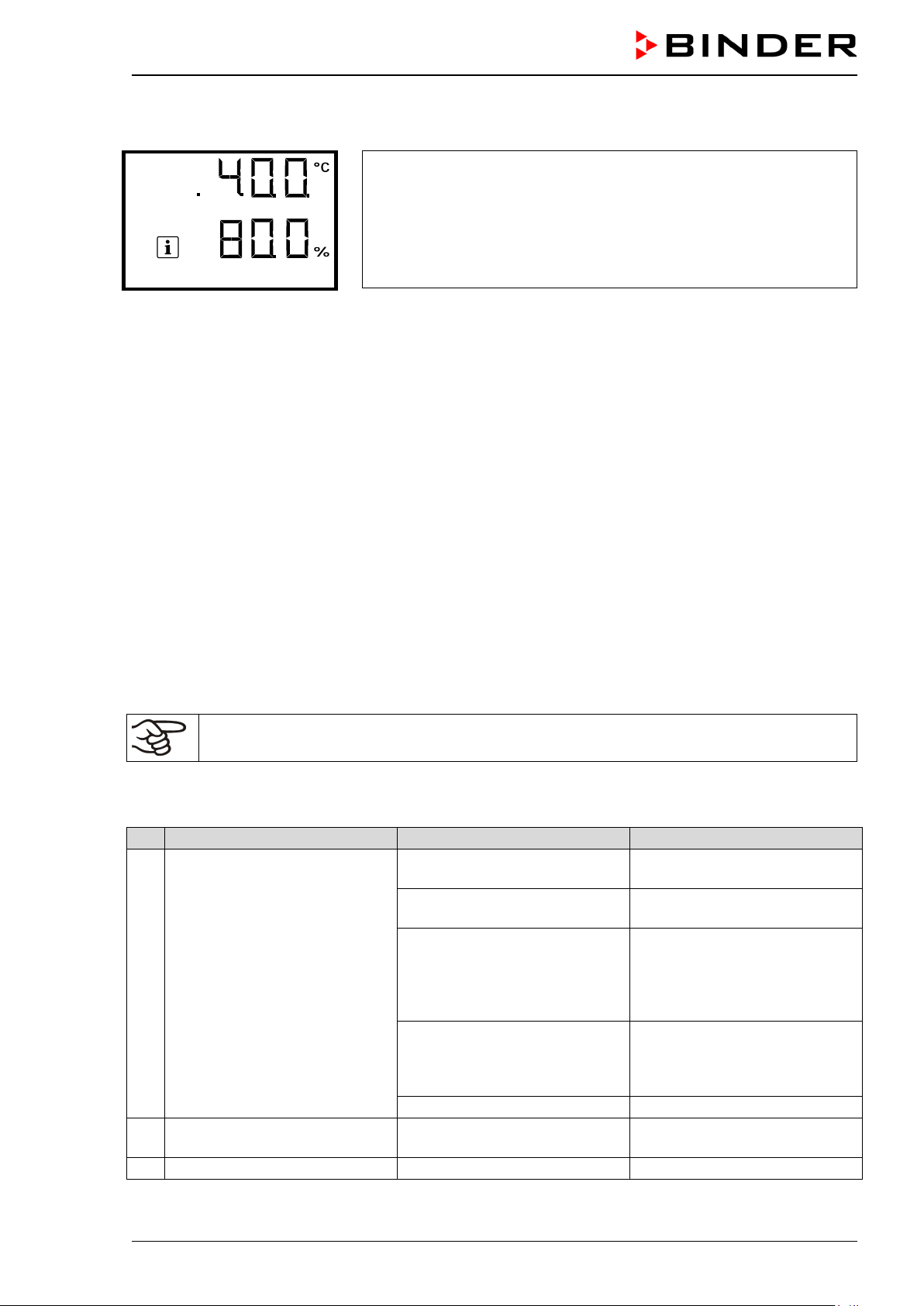
Service due!
No.
Fault description
Possible cause
Required measures
Check connection to power
supply.
Check power supply for voltage
of 120 V / 230 V.
Nominal temperature exceeded
(chap. 11.1).
Check chamber fuse and re-
service.
Controller defective.
Contact BINDER service.
Set-point values are not equilibrated. Icon “1” is displayed.
Operating mode “Idle mode”
activated.
Deactivate operating mode “Idle
mode” (chap. 9.1)
3
Alarm message “Door open”.
The outer chamber door is open
Close chamber door.
After the recomm ended maintenance interval (one year of operation) a m essage appears on the contro ller.
The information message “Service due!” is shown in the text field of
the controller display.
Press the OK button to confirm the message.
After one week of operation, the message reappears.
24.4 Gas inlet fine filter
When the cham ber is operatin g, the incom ing gas passes throug h a fine gas filter (aseptic fil ter, filtrat ion
efficiency 99.99%, p article size 0.45 µm). The gas f ine filter prevents dirt accum ulating in the gas inlet
valves and the tubes lead ing into the inner cham ber, which could be in the g as cylinder or in the supp ly
tubes.
Service personnel aut horized by BINDER will ch eck this filter for pol lution at each maintenanc e interval
and replace it, if appropriate, but at least once a year.
24.5 S imple troubleshooting
Defects and shortcom ings can compromise the operational saf ety of the chamber and can lead to risk s
and damage to equipm ent and per sons. If ther e are is a technical f ault or shor tcom ing, take the c hamber
out of operation and inform BINDER Ser vice. If you are n ot sure whether ther e is a technical fau lt, proceed according to th e following list. If you cannot cle arly identify an error or there is a technical fault,
please contact BINDER Service.
Only qualified service personnel authorized by BINDER must perform repair.
Repaired chambers must comply with the BINDER quality standards.
24.5.1 General
No power supply.
Wrong voltage.
by 10 °C due to chamber fail-
1 Chamber without function.
ure. Over temperature protective device (class 1) responds
The miniature fuse for overcurrent protection has triggered
(chap. 26.2).
Contact BINDER service.
place it if appropriate. If it responds again, contact BINDER
2
CB-S / CB-S-UL (E7) 06/2020 page 95/119
Page 96

No.
Fault description
Possible cause
Required measures
Pt 100 sensor defective.
Heating element defective.
Semiconductor relay defective.
Chamber is heating permanently. Set-point is not respected.
Doors not closed.
Close door properly.
Door gaskets defective.
Replace door gaskets.
Controller defective.
Pt 100 sensor defective.
Controller not adjusted.
Calibrate and adjust controller.
Current actual temperature
no. 3.
Operation temporarily possible.
cause.
Select cooler place of installation (chap. 3.4).
Difference between the set
temperature too low.
Difference between the set
temperature at least 6 °C.
Too much external heat load.
Reduce heat load.
Controller defective.
Semiconductor relay defective.
Controller not adjusted.
Calibrate and adjust controller.
Sterilization terminated prematurely.
Current actual temperature
no. 5.
Operation temporarily possible.
cause.
Check the setting of the safety
(chap. 11.2).
Sterilization terminated prematurely.
Actual temperature value dis-
“Inner temp. sensor”
Inner temperature sensor defec-
sensor.
Alarm messages “Safety consor” alternating
Actual temperature value dis-
ing
Alarm message “Door heating
sensor”
24.5.2 Temperature
1 Chamber does not heat up.
2
3 Temperature inside too low.
Temperature inside too low.
4
Alarm message
“Temperature range”
5 Temperature inside too high.
Contact BINDER service.
Semiconductor relay defective. Contact BINDER service.
Contact BINDER service.
value outside the tolerance
range.
For causes and actions, see
Check the tolerance range settings. With other error messages remove the respective
Installation site too warm .
temperature and the ambient
temperature and the ambient
Contact BINDER service.
Temperature inside too high.
6
Alarm message
“Temperature range”
Alarm message
7
“Safety controller”
play shows “ – – – – ”.
8
Alarm message
9
troller” and “Safety control sen-
play shows “ – – – – ”.
Alarm messages “Inner temp.
10
sensor”, “Safety controller”, and
“Safety control sensor” alternat-
value outside the tolerance
range.
For causes and actions, see
Safety controller (chap. 11.2)
set too low.
tive. Control continues using the
safety controller temperature
Safety controller temperature
sensor defective.
Inner temperature sensor and
safety controller temperature
sensor defective.
Let the chamber cool down.
Check the tolerance range settings. With other error messages remove the respective
controller. If appropriate, select
suitable safety controller value
Let the chamber cool down.
Operation temporarily possible.
Contact BINDER service.
Turn off the chamber. Contact
BINDER service.
Turn off the chamber. Contact
BINDER service.
11
CB-S / CB-S-UL (E7) 06/2020 page 96/119
Door heating sensor defective. Contact BINDER service.
Page 97

No.
Fault description
Possible cause
Required measures
CO2 set-point values are not
played.
CO2 cylinder is not connected
correctly.
Correctly connect the gas cylinder.
Connected gas cylinder is
closed or empty.
Check the tube system for dirt
clean or replace it.
Pressure sensor system defective
Doors not closed.
Close door properly.
Door gaskets defective.
Replace door gaskets.
CO2 cylinder is not connected
correctly.
Correctly connect the gas cylinder.
Connected gas cylinder is
closed or empty.
Check the tube system for dirt
clean or replace it.
Controller not adjusted.
Calibrate and adjust controller
Operation temporarily possible.
cause.
Controller defective
Contact BINDER service.
Controller not adjusted.
Calibrate and adjust controller
Operation temporarily possible.
cause.
Actual CO2 value display shows
“CO2 sensor defective”
Turn off the chamber. If appro-
4.2). Contact BINDER service.
Actual CO2 value display shows
“ – – – – ”.
Turn off the chamber. Connect
CO2 sensor (chap. 4.2.1).
Actual value of CO2 deviates
color
Calibrate and adjust CO2 sen-
Recovery time (up to 5 vol.-%
2 minutes is < 2 minutes.
Obstructed gas supply.
Insufficient CO2 input pressure.
Gas fine filter obstructed.
Contact BINDER service.
24.5.3 CO2
1
equilibrated. Icon “2” is dis-
Alarm message “CO2 pres-
2
sure”.
concentration inside too
CO
3
2
low.
CO2 control is deactivated. Activate CO2 control (chap. 9.2)
Open or replace gas cylinder.
Gas hose is dirty or obstructed.
accumulation or obstruction,
Contact BINDER service.
Open or replace gas cylinder.
CO
concentration inside too
2
low.
4
Alarm message “CO2 range”.
concentration inside too
CO
5
6
2
high
CO
concentration inside too
2
high. Alarm message
“CO2 range”.
“ – – – – ”. Alarm message
7
largely compared with a reference method.
8
The pH indicator of the cell
medium changes its normal
Gas hose is dirty or obstructed.
Current actual CO
value out-
2
side the tolerance range.
For causes and actions, see
no. 3.
Current actual CO
value out-
2
side the tolerance range.
For causes and actions, see
no. 5.
CO2 sensor defective.
CO2 sensor not connected,
CO2 sensor not adjusted.
CO2 sensor system defective.
accumulation or obstruction,
Check the tolerance range settings. With other error messages remove the respective
Check the tolerance range settings. With other error messages remove the respective
priate, replace sensor (chap.
sor
Transfer the cultures to another
incubator and contact BINDER
Service.
9
CO2) after doors were open for
Recovery time (up to 5 vol.-%
10
CO2) after doors were open for
2 minutes is > 10 minutes.
CB-S / CB-S-UL (E7) 06/2020 page 97/119
CO2 sensor system defective. Contact BINDER service.
Check gas supply (cylinder,
connections, hose system).
Page 98

No.
Fault description
Possible cause
Required measures
Door gaskets defective.
Replace door gaskets.
Gas fine filter not connected
correctly
No.
Fault description
Possible cause
Required measures
Fill the water pan with water
chamber (chap. 4.3).
Increase or decrease humidity
via humidity control (chap. 14.1)
Water pan filled with water
when incubator is not operating
Empty water pan when incubator is not operating.
Doors not closed.
Close door properly.
Door gaskets defective.
Replace door gaskets.
Place the chamber on a
distance to the floor.
Doors not closed.
Close door properly.
Door gaskets defective.
Replace door gaskets.
Door heating defective
Contact BINDER service.
Setting the door heating Offset
value (chap. 14.2)
Contact BINDER service to
No.
Fault description
Possible cause
Required measures
No chamber function. Dark
display.
Menu functions not available
with current authorization level.
Log in with the required higher
authorization.
3
No access to controller
Password incorrect.
Contact BINDER service.
Remove cause of alarm. If the
BINDER service.
No.
Fault description
Possible cause
Required measures
Alarm message
“Sterilization failed”
Sterilization terminated prematurely after less than 6 hours.
If required, repeat sterilization
(chap. 23.3).
Turn off the chamber and re-
23.3.1)
Unusually high gas consump-
11
tion.
Contact BINDER service.
24.5.4 Humidity
with distilled, sterile water. T he
1 No or too low humidity inside.
Condensations inside the
2
chamber..
Water pan empty.
Unfavorable ambient conditions.
pan must have thorough contact
to the bottom of the inner
3 Condensation on the door.
Humidity recovery time too long
4
following door opening.
24.5.5 Controller
1
2 Menu functions not available.
Acknowledging the alarm does
4
not cancel the alarm state.
Chamber placed on very cold
floor.
BINDER stand to increase the
Unfavorable ambient conditions.
Frequent and longer door openings.
adapt the heating power for the
humidity recovery time (chap.
14.3).
Main power switch is off. Turn on the main power switch.
Cause of alarm persists.
alarm state continues, contact
24.5.6 Sterilization
1
Information message
2
“CO2 sensor plugged-in”
CB-S / CB-S-UL (E7) 06/2020 page 98/119
Trying to start sterilization cycle
while the CO
sensor still
2
plugged-in
move CO2 sensor (chap. 4.2).
Restart sterilization (chap.
Page 99

No.
Fault description
Possible cause
Required measures
Information message
door” icons are displayed
If necessary, let cool down the
chamber back into operation.
Return address:
BINDER GmbH
Gänsäcker 16
Germany
“Sterilization”.
3
“STE” and “Do not open the
Information message
“Sterilization success”
4
“STE” icon is displayed.
Sterilization cycle is running.
Sterilization successfully completed.
Wait at least 6 hours before
terminating the sterilization
cycle. Do not open the door.
chamber.
Turn off the chamber, connect
the CO
sensor and put the
2
24.6 S ending the chamber back to BINDER GmbH
If you return a BINDER pro duct to us f or repair or an y other reaso n, we will on ly acc ept the produc t upon
presentation of an authorization number (RMA number) that has previously been issued to you. An
authorization num ber will be issued after r eceiving your com plaint either in writin g or by telephone prior
to your sending the BIND E R pr oduc t b ac k t o us. T he auth or i zation n umber will be issued fol low ing rec e ipt
of the information below:
• BINDER product type and serial number
• Date of purchase
• Name and address of the dealer from which you bought the BINDER product
• Exact description of the defect or fault
• Complete address, contact person and availability of that person
• Exact location of the BINDER product in your facility
• A contamination clearance certificate (chap. 29) must be faxed in advance
The authorization number must be applied to the packaging in such a way that it can be easily recognized
or be recorded clearly in the delivery documents.
For security reasons we cannot accept a chamber delivery if it does not carr y an authori zat ion
number.
Abteilung Service
78502 Tuttlingen
CB-S / CB-S-UL (E7) 06/2020 page 99/119
Page 100

Packing element
Material
Disposal
Packing element
Material
Disposal
Door protection
PE foam
Plastic recycling
Packing box equipment
Cardboard
Paper recycling
Insulating air cushion foil
PE foil
Plastic recycling
Paperboard
Cardboard
Paper recycling
Do not open. Dispose of with
normal waste
Cardboard
Paper recycling
PE foam
Plastic recycling
Bag for operating manuals
PE foil
Plastic recycling
25. Disposal
25.1 Disposal of the transport packing
25.1.1 Outer chamber packing
Straps to fix packing on pallet
(no image)
Plastic Plastic recycling
Shipping box Cardboard Paper recycling
Edge stuffing, top PE foam Plastic recycling
PE foam Plastic recycling
Pallet with foamed plastic
stuffing
Solid wood
(IPPC standard)
Wood recycling
25.1.2 Packing inside the chamber, equipment
Silica gel bag Paper with silica gel
Sensor packing
If recycling is not possible, all packing parts can also be disposed of with normal waste.
CB-S / CB-S-UL (E7) 06/2020 page 100/119
 Loading...