

Page 1

CB 60-UL
100-120V
9040-0089, 9140-0089
CB 60
230 V
O2 control
9040-0090, 9140-0090
CB 60-UL
100-120V
O2 control
9040-0091, 9140-0091
CB 60
230 V
Divided inner door
9040-0104, 9140-0104
CB 60-UL
100-120V
Divided inner door
9040-0105, 9140-0105
CB 60
230 V
O2 control
Divided inner door
9040-0106, 9140-0106
CB 60-UL
100-120V
O2 control
Divided inner door
9040-0107, 9140-0107
CB 160 (E6)
230 V
9040-0092, 9140-0092
CB 160-UL
100-120V
9040-0093, 9140-0093
CB 160 (E6)
230 V
O2 control
9040-0094, 9140-0094
CB 160-UL
100-120V
O2 control
9040-0095, 9140-0095
CB 160
230 V
Divided inner door
9040-0100, 9140-0100
CB 160-UL
100-120V
Divided inner door
9040-0101, 9140-0101
CB 160
230 V
O2 control
Divided inner door
9040-0102, 9140-0102
CB 160-UL
100-120V
O2 control
Divided inner door
9040-0103, 9140-0103
CB 220
230 V
9040-0096, 9140-0096
CB 220-UL
100-120V
9040-0097, 9140-0097
CB 220
230 V
O2 control
9040-0098, 9140-0098
CB 220-UL
100-120V
O2 control
9040-0099, 9140-0099
CB 220
230 V
Divided inner door
9040-0108, 9140-0108
CB 220-UL
100-120V
Divided inner door
9040-0109, 9140-0109
CB 220
230 V
O2 control
Divided inner door
9040-0110, 9140-0110
CB 220-UL
100-120V
O2 control
Divided inner door
9040-0111, 9140-0111
Operating Manual
CB (E6.1)
CO
CO
- Incubators
2
– Incubators with O2 control
2
with sterilizable NDIR sensor system for CO2
and microprocessor controller T4.12
Model Voltage Equipment Art. No.
CB 60
230 V 9040-0088, 9140-0088
BINDER GmbH
Address: Post office box 102, 78502 Tuttlingen, Germany Phone: +49 7462 2005 0
Fax: +49 7462 2005 100 Internet: http://www.binder-world.com
E-mail: info@binder-world.com Service Hotline: +49 7462 2005 555
Service Fax: +49 7462 2005 93 555 Service E-Mail: service@binder-world.com
Service Hotline USA: +1 866 885 9794 or +1 631 2 24 4340 x3
Service Hotline Asia Pacific: +852 390 705 04 or +852 390 705 03
Service Hotline Russia and CIS: +7 495 988 15 16
Issue 07/2017 Art. No. 7001-0333
Page 2

Contents
1. SAFETY .................................................................................................................. 6
1.1 Legal considerations ........................................................................................................................... 6
1.2 Structure of the safety instructions ...................................................................................................... 6
1.2.1 Signal word panel ..................................................................................................................... 6
1.2.2 Safety alert symbol ................................................................................................................... 7
1.2.3 Pictograms ................................................................................................................................ 7
1.2.4 Word message panel structure ................................................................................................. 8
1.3 Localization / position of safety labels on the chamber ...................................................................... 8
1.4 Type plate ......................................................................................................................................... 10
1.5 General safety instructions on installing and operating the CO2 incubator ...................................... 11
1.6 Precautions when working with gases .............................................................................................. 12
1.7 Precautions when handling gas cylinders ......................................................................................... 14
1.8 Intended use ..................................................................................................................................... 15
2. CHAMBER DESCRIPTION .................................................................................. 16
2.1 Chamber overview ............................................................................................................................ 17
2.2 Instrument panel ............................................................................................................................... 17
2.3 Inner chamber ................................................................................................................................... 18
2.4 Control panel on the rear of the chamber ......................................................................................... 20
3. COMPLETENESS OF DELIVERY, TRANSPORTATION, STORAGE, AND
INSTALLATION .................................................................................................... 21
3.1 Unpacking, and checking equipment and complet eness of delivery ................................................ 21
3.2 Guidelines for safe lifting and transportation..................................................................................... 21
3.3 Storage .............................................................................................................................................. 22
3.4 Location of installation and ambient condi tions ................................................................................ 22
4. INSTALLATION AND CONNECTIONS ............................................................... 26
4.1 Shelves.............................................................................................................................................. 26
4.2 Permadry™ water pan ...................................................................................................................... 26
4.3 Connecting the O2 sensor (chamber with O2 control) ....................................................................... 27
4.4 Gas connections ............................................................................................................................... 28
4.4.1 Connection of the CO2 gas cylinder ........................................................................................ 29
4.4.2 Connection of the O2 gas cylinder (chamber with O2 control and optional alternative control
range 10 up to 95 vol.-% O
4.4.3 Connection of the N2 gas cylinder (chamber with O2 control)................................................. 31
4.4.4 Connecting the gas hose to the chamber rear (for CO2, O2, N2) ............................................ 32
4.4.5 Gas cylinder connection kits (option) ...................................................................................... 33
4.5 Electrical connection ......................................................................................................................... 34
4.6 Handling and aligning the divided inner door, gas proof (optional equipment) ................................. 35
) .................................................................................................. 30
2
5. START UP ............................................................................................................ 36
5.1 Equilibration time ............................................................................................................................... 36
5.2 Factory settings ................................................................................................................................. 36
6. FUNCTIONAL OVERVIEW OF THE T4.12 CHAMBER CONTROLLER ............. 37
6.1 Menu structure .................................................................................................................................. 38
6.1.1 General menu ......................................................................................................................... 38
6.1.2 Quick menu ............................................................................................................................. 39
6.1.3 User menu .............................................................................................................................. 40
6.2 Operating modes ............................................................................................................................... 41
6.2.1 Activating the “control off” mode or change to “f i xed value” operating mode ......................... 41
6.3 Deactivating the O2 control and O2/N2 pressure alarms (chamber with O2 control) ......................... 43
6.3.1 Required gas supply of the chamber with O2 control ............................................................. 43
6.3.2 Activating / deactivating the O2 control and O2 / N2 pressure alarms ..................................... 44
CB (E6.1) 07/2017 Page 2/145
Page 3

6.4
Humidity control of the Permadry™ system ...................................................................................... 45
6.5 Turning on / off the interior socket voltage (wit h optional interior socket) ......................................... 46
6.6 Performance during and after power failure ...................................................................................... 46
6.7 Information ........................................................................................................................................ 47
7. SETPOINT ENTRY ............................................................................................... 48
7.1 Setting ranges ................................................................................................................................... 48
7.2 Note when setting high gas concentrations ...................................................................................... 48
7.3 Entering the setpoints via “quick menu” ............................................................................................ 50
7.4 Entering the setpoints via general menu ........................................................................................... 52
8. KEY LOCK ........................................................................................................... 54
8.1 Directly activating the key lock .......................................................................................................... 55
8.2 Automatic key lock ............................................................................................................................ 55
8.3 Changing the password for unlocking the key lock ........................................................................... 57
9. GENERAL CONTROLLER SETTINGS ................................................................ 58
9.1 Setup wizard ..................................................................................................................................... 59
9.2 Date and time settings ...................................................................................................................... 59
9.3 Selecting the menu language of the T4.12 controller ....................................................................... 61
9.4 Setting display brightness ................................................................................................................. 61
9.5 Changing the temperature unit ......................................................................................................... 62
9.6 Defining the data recording rate ........................................................................................................ 62
9.7 Factory reset ..................................................................................................................................... 63
9.8 Network configuration ....................................................................................................................... 63
9.9 Display of the network configuration ................................................................................................. 67
9.10 RS 422 address (with optional RS 422 interface) ............................................................................. 68
9.11 Display and entry of the device configuration – for se rvice purpose ................................................ 68
10. DATA TRANSFER VIA USB INTERFACE .......................................................... 69
10.1 Exporting data to USB drive .............................................................................................................. 69
10.2 Importing data from USB drive .......................................................................................................... 70
11. NOTIFICATIONS AND ALARMS ......................................................................... 71
11.1 Notifications overview ....................................................................................................................... 71
11.2 Alarm messages overview ................................................................................................................ 71
11.3 Alarm status ...................................................................................................................................... 73
11.4 Confirming an active “set” alarm ....................................................................................................... 74
11.5 Alarm configuration and overview ..................................................................................................... 75
11.5.1 List of active alarms ................................................................................................................ 75
11.5.2 History – list of all alarms ........................................................................................................ 76
11.5.3 Activating, deactivating, and testing the alarm buzzer ........................................................... 77
11.5.4 Activating / deactivating all alarm functions ............................................................................ 77
11.5.5 Setting the delay time after opening the door ......................................................................... 78
11.5.6 Tolerance ranges and alarm delay times ............................................................................... 78
11.6 Zero-voltage relay alarm output ........................................................................................................ 82
12. EVENT LIST ......................................................................................................... 83
13. GRAPHICAL DISPLAY OF THE MEASURED VALUES ..................................... 84
13.1 Setting the sampling rate .................................................................................................................. 84
13.2 Defining the display range................................................................................................................. 85
13.3 Selecting the parameters .................................................................................................................. 86
14. TEMPERATURE SAFETY DEVICES ................................................................... 87
14.1 Overtemperature protective device (class 1) .................................................................................... 87
14.2 Overtemperature safety controller (temperature safety device class 3.1) ........................................ 87
14.2.1 Safety controller modes .......................................................................................................... 87
14.2.2 Setting the safety controller .................................................................................................... 88
CB (E6.1) 07/2017 Page 3/145
Page 4

15. OPTIONS .............................................................................................................. 91
15.1 Communication software APT-COM™ 3 DataControlSystem (option)............................................. 91
15.2 RS 422 interface (option) .................................................................................................................. 91
15.3 Silicone access ports 30 mm / 1.18 in, closable from both sides with silicon plugs (option) ............ 91
15.4 Interior socket 230V (option) ............................................................................................................. 92
15.5 Analog outputs for temperature and CO2 (option) ............................................................................ 94
15.6 Access port for extra-low voltage (option) ......................................................................................... 94
15.7 BINDER Gas Supply Service – External bottle cha nger for CO2, N2 or O2 (option) ......................... 95
15.8 Stands ............................................................................................................................................... 96
15.8.1 Stacking stand (option) ........................................................................................................... 96
15.8.2 Stacking adapter for direct thermal decoupled stac king (option) ........................................... 96
15.8.3 Base on castors (option) ......................................................................................................... 96
16. REFERENCE MEASUREMENTS ........................................................................ 97
16.1 CO2 reference measuring ................................................................................................................. 97
16.1.1 Measuring CO2 concentration indirectly via the pH of the cell m edium .................................. 97
16.1.2 Measuring CO2 directly via chemical indicator tubes ............................................................. 98
16.1.3 Measuring CO2 directly with an electronic infrared measuring device ................................... 99
16.2 Temperature reference measurement .............................................................................................. 99
17. AVOIDING MICROBIAL CONTAMINATION........................................................ 99
17.1 Cells and media ................................................................................................................................ 99
17.2 Laboratory conditions / equipment aroun d the incubator .................................................................. 99
17.3 Working and behavior in the lab ..................................................................................................... 100
17.4 Chamber design and equipment of the CO2 incubator ................................................................... 100
17.5 Handling the CO2 incubator ............................................................................................................ 101
18. CLEANING, DECONTAMINATION / DISINFECTION, AND STERILIZATION .. 103
18.1 Cleaning .......................................................................................................................................... 103
18.2 Decontamination / chemical disinfection of the chamber ................................................................ 105
18.3 Hot-air sterilization at 180 °C / 356 °F............................................................................................. 106
18.3.1 Overview ............................................................................................................................... 106
18.3.2 Performing a hot-air sterilization ........................................................................................... 107
18.3.3 Aborting the hot-air sterilization – general procedure ........................................................... 109
18.3.4 Aborting hot-air sterilization after less than 4 hours ............................................................. 110
18.3.5 Terminating successful sterilization during the cooling-down phase (abortion after more than
4 hours) ................................................................................................................................. 112
18.3.6 Terminating the completed sterilization cycle ....................................................................... 113
19. MAINTENANCE AND SERVICE ........................................................................ 115
19.1 Maintenance intervals, service ........................................................................................................ 115
19.2 Checking the air jacket heating fan ................................................................................................. 116
19.3 Checking the humidity system fan .................................................................................................. 116
19.4 Gas inlet fine filter ........................................................................................................................... 116
19.5 Sending the chamber back to BINDER GmbH ............................................................................... 116
20. DISPOSAL ......................................................................................................... 117
20.1 Disposal of the transport packing .................................................................................................... 117
20.1.1 Outer chamber packing ........................................................................................................ 117
20.1.2 Packing inside the chamber and equipment ......................................................................... 117
20.2 Decommissioning ............................................................................................................................ 118
20.3 Disposal of the chamber in the Federal Republic of Germany ....................................................... 118
20.4 Disposal of the chamber in the member states of the EU except for the Federal Republic of
Germany.......................................................................................................................................... 119
20.5 Disposal of the chamber in non-member states of the EU ............................................................. 120
CB (E6.1) 07/2017 Page 4/145
Page 5

21. TROUBLESHOOTING ....................................................................................... 121
21.1 General............................................................................................................................................ 121
21.2 Heating ............................................................................................................................................ 121
21.3 Gas cylinder pressure too low ......................................................................................................... 123
21.4 Gas concentration ........................................................................................................................... 124
21.5 Sterilization ...................................................................................................................................... 126
21.6 Humidity .......................................................................................................................................... 126
21.7 Controller ......................................................................................................................................... 127
21.8 Open door ....................................................................................................................................... 127
22. TECHNICAL DESCRIPTION .............................................................................. 128
22.1 Factory calibration and adjustment ................................................................................................. 128
22.2 Over current protection ................................................................................................................... 128
22.3 Definition of usable volume ............................................................................................................. 128
22.4 CB technical data ............................................................................................................................ 129
22.5 Equipment and Options ................................................................................................................... 131
22.6 Accessories and spare parts (extract) ............................................................................................ 132
22.7 Important conversion data for non-SI units ..................................................................................... 133
22.8 Conversion table for gas inlet pressures, bar – psi ......................................................................... 133
22.9 Dimensions CB 60 .......................................................................................................................... 134
22.10 Dimensions CB 160 ........................................................................................................................ 135
22.11 Dimensions CB 220 ........................................................................................................................ 136
23. CERTIFICATES AND DECLARATIONS OF CONF ORMITY ............................. 137
23.1 EU Declaration of conformity .......................................................................................................... 137
24. PRODUCT REGISTRATION .............................................................................. 139
25. CONTAMINATION CLEARANCE CERTIFICATE ............................................. 140
25.1 For chambers located outside the USA and Canada ..................................................................... 140
25.2 For chambers in the USA and Canada ........................................................................................... 143
CB (E6.1) 07/2017 Page 5/145
Page 6
Dear customer,
For the correct operation of the CO
completely and carefully and observe all instructions as indicated. Failure to read, understand and follow
the instructions may result in personal injury. It can also lead to damage to the chamber and/or poor
equipment performance
incubator CB, it is important that you read this operating manual
2
1. Safety
This operating manual is part of the components of delivery. Always keep it handy for reference. The
device should only be operated by laboratory personnel especially trained for this purpose and familiar
with all precautionary measures required for working in a laboratory. Observe the national regulations on
minimum age of laboratory personnel. To avoid injuries and damage observe the safety instructions of the
operating manual.
WARNING
Failure to observe the safety instructions.
Serious injuries and chamber damage.
Observe the safety instructions in this operating manual.
Carefully read the complete operating instructions of the chamber.
1.1 Legal considerations
This operating manual is for informational purposes only. It contains information for installing, start-up,
operation and maintenance of the product. Note: the contents and the product described are subject to
change without notice.
Understanding and observing the instructions in this operating manual are prerequisites for hazard-free
use and safety during operation and maintenance. In no event shall BINDER be held liable for any
damages, direct or incidental arising out of or related to the use of this manual.
This operating manual cannot cover all conceivable applications. If you would like additional information,
or if special problems arise that are not sufficiently addressed in this manual, please ask your dealer or
contact us directly by phone at the number located on page one of this manual
Furthermore, we emphasize that the contents of this operating manual are not part of an earlier or
existing agreement, description, or legal relationship, nor do they modify such a relationship. All
obligations on the part of BINDER derive from the respective purchase contract, which also contains the
entire and exclusively valid statement of warranty administration. The statements in this manual neither
augment nor restrict the contractual warranty provisions.
1.2 Structure of the safety instructions
In this operating manual, the following safety definitions and symbols indicate dangerous situations
following the harmonization of ISO 3864-2 and ANSI Z535.6.
1.2.1 Signal word panel
Depending on the probability of serious consequences, potential dangers are identified with a signal
word, the corresponding safety color, and i f appropriate, the safety alert symbol.
DANGER
Indicates an imminently hazardous situation that, if not avoided, will result in death or serious
(irreversible) injury.
CB (E6.1) 07/2017 Page 6/145
Page 7
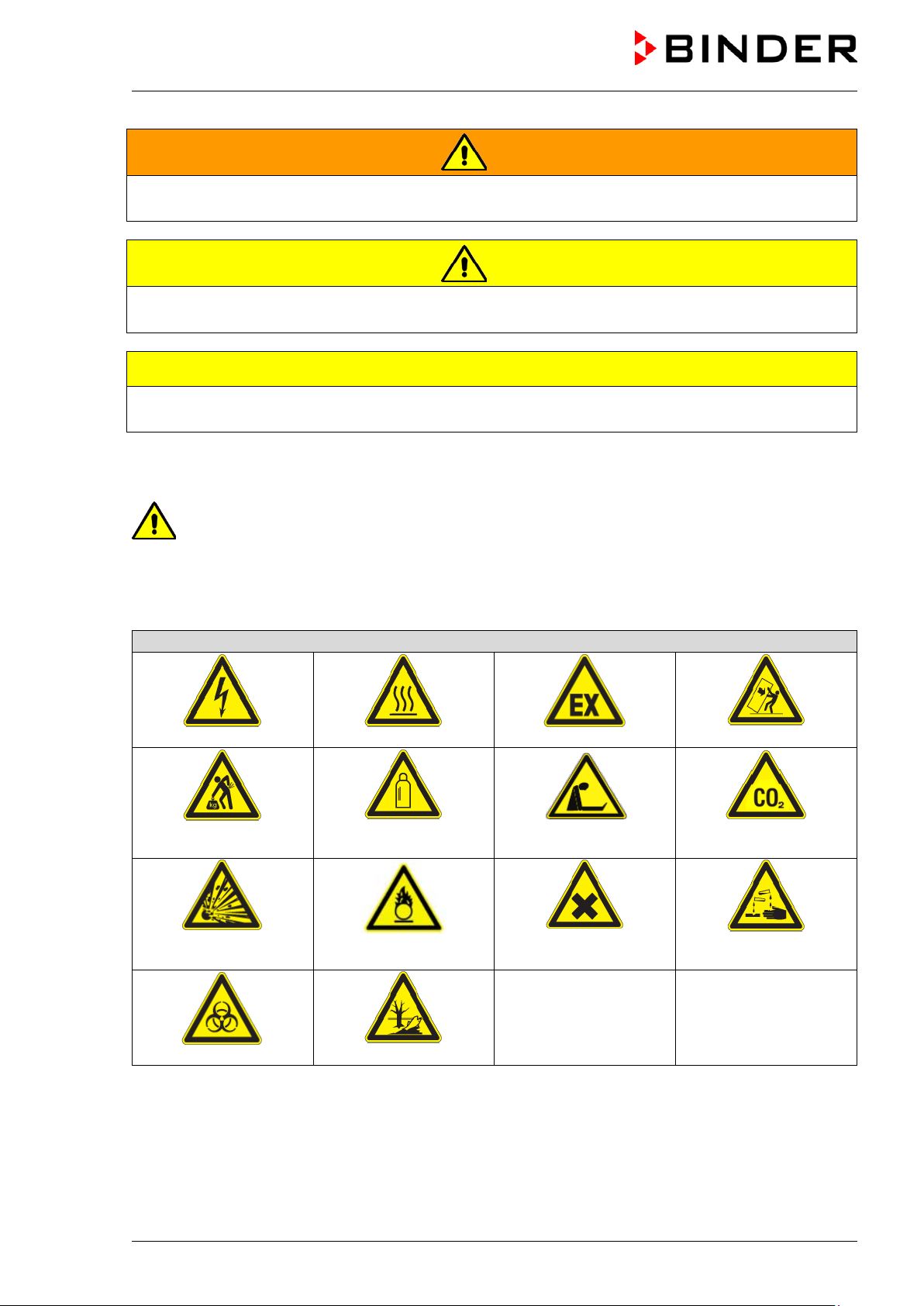
CAUTION
Warning signs
Electrical hazard
Hot surface
Explosive atmosphere
poisoning hazard
or chemical burns
Biohazard
WARNING
Indicates a potentially hazardous situation which, if not avoided, could result in death or serious
(irreversible) injury.
CAUTION
Indicates a potentially hazardous situation which, if not avoided, may result in moderate or minor
(reversible) injury.
Indicates a potentially hazardous situation which, if not avoided, may result in damage to the product
and/or its functions or of a property in its prox i m i ty.
1.2.2 Safety alert symbol
Use of the safety alert symbol indicates a risk of injury.
Observe all measures that are marked with the saf ety alert symbol in order to avoid death or
injury.
1.2.3 Pictograms
Lifting hazard
Explosive substances
Gas cylinders
Fire promoting agents
Suffocation hazard
Harmful substances
Stability hazard
suffocation and
CO
2
Risk of corrosion and /
CB (E6.1) 07/2017 Page 7/145
Pollution Hazard
Page 8
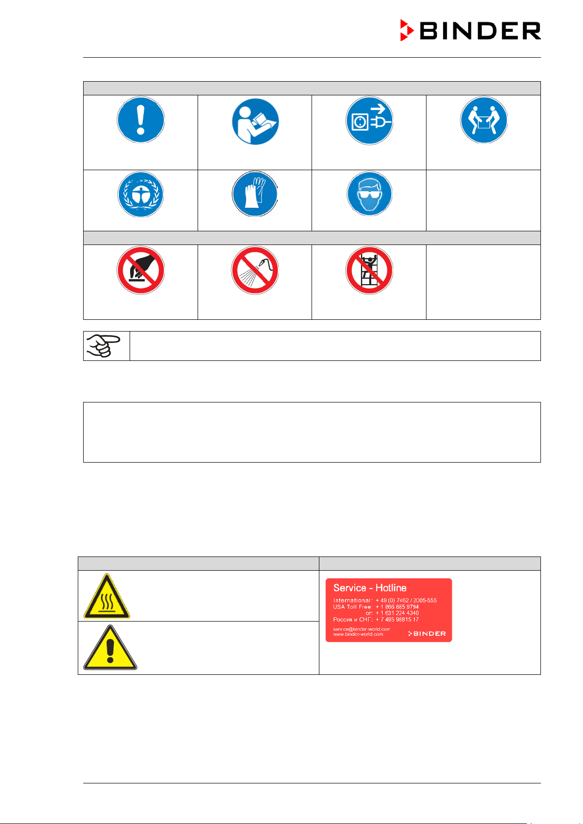
Mandatory action signs
plug
Environment protection
Prohibition signs
water
Pictograms (Warning signs)
Service label
Mandatory regulation
Do NOT touch
Information to be observed in order to ensure optim um function of the product.
Read operating
instructions
Wear protective gloves
Do NOT spray with
1.2.4 Word message panel structure
Type / cause of hazard.
Possible consequences.
Instruction how to avoid the hazard: prohibition
Instruction how to avoid the hazard: mandatory a ct i on
Disconnect the power
Wear safety goggles
Do NOT climb
Lift with several persons
Observe all other notes and information not necessarily emphasized in the same way, in order to avoid
disruptions that could result in direct or indirect injury or property damage.
1.3 Localization / position of safety labels on t he chamber
The following labels are located on the chamber:
Hot surface
• on the outer chamber door
Risk of injury
• on the outer door: CB-UL only
• above the access ports (option)
CB (E6.1) 07/2017 Page 8/145
Page 9
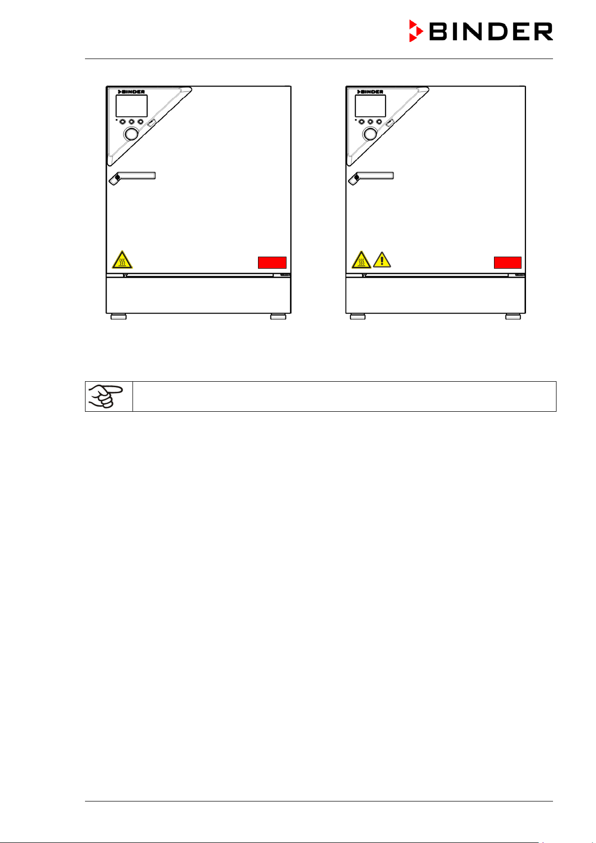
CO2 -Incubator CB CO2 -Incubator CB-UL
Figure 1: Position of labels on the chamber
Keep safety labels complete and legible.
Replace safety labels that are no longer legible. Contact BINDER service for these replacements.
CB (E6.1) 07/2017 Page 9/145
Page 10
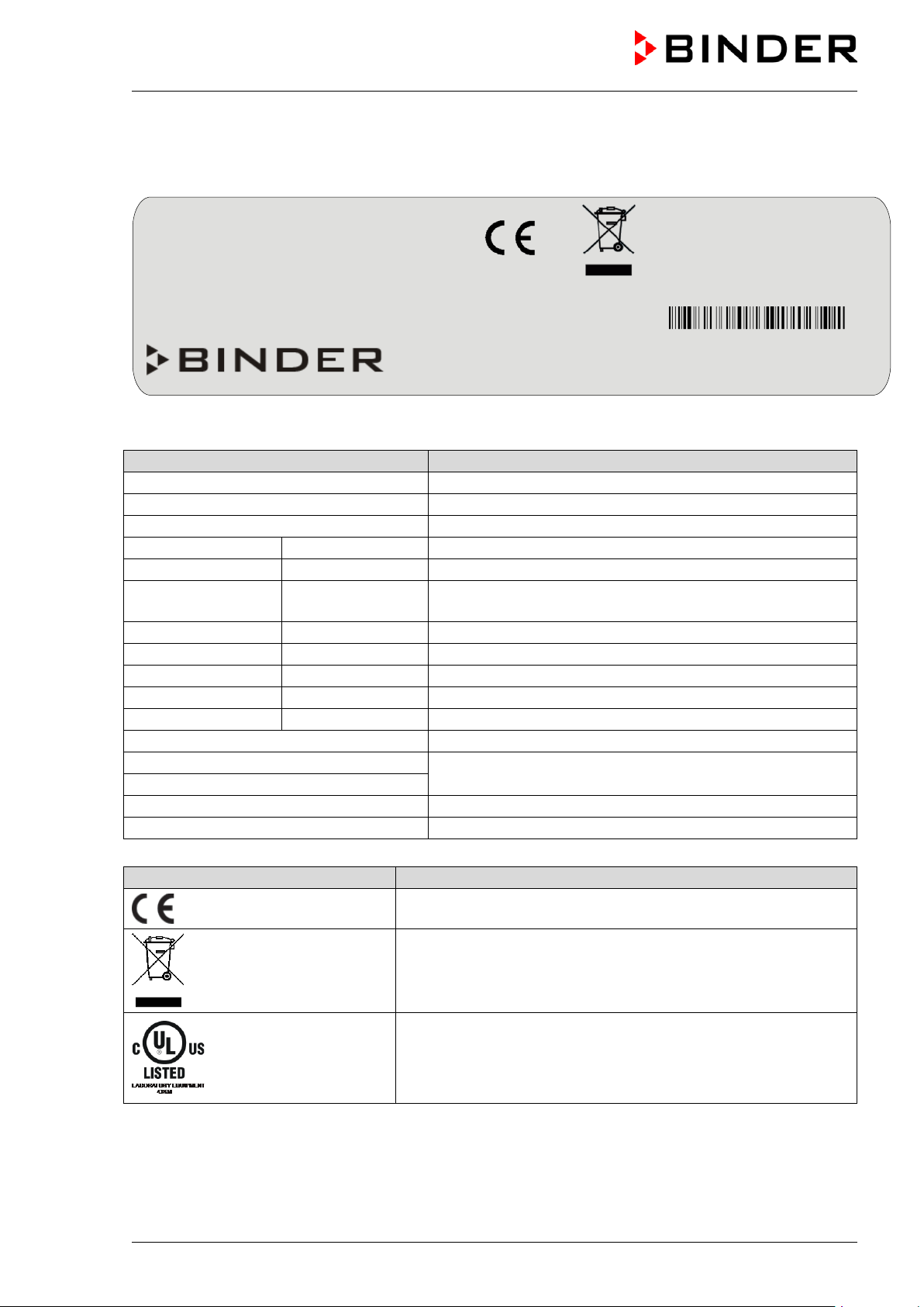
Indications of the type plate (example)
Information
BINDER
Manufacturer: BINDER GmbH
CB 160
Model designation
CO2 incubator
Device name
Serial No.
00000000000000
Serial no. of the chamber
Built
2017
Year of construction
Nominal
187 °C
369 °F
IP protection
20
IP type of protection acc. to standard EN 60529
Temp. safety device
DIN 12880
Temperature safety device acc. to standard DIN 12880
Class
3.1
Class of temperature safety device
Art. No.
9040-0092
Art. No. of the chamber
Project No.
---
Optional: Special application acc. to project no.
1,30 kW
Nominal power
230 V / 50 Hz
230 V / 60 Hz
1 N ~
Current type
5,7 A
Nominal current
Symbol on the type plate
Information
Nominal temp.
187 °C
1,30 kW / 5,7 A
369 °F
230 V / 50 Hz
IP protection
20
230 V / 60 Hz
Safety device
DIN 12880
1 N ~
Class
3.1
Art. No.
9040-0092
Built
2017
CO2 incubator
BINDER GmbH
www.binder-world.com
CB 160
Serial No. 00000000000000
1.4 Type plate
Position of type plate: left chamber side (see n from front), at the bottom in the middle
Project No.
temperature
Im Mittleren Ösch 5
78532 Tuttlingen / Germany
E6.1
Made in Germany
Figure 2: Type plate (example of CB 160 regular chamber)
Nominal temperature
Nominal voltage ± 10% at the indicated power fre quency
CE conformity marking
Electrical and electronic equipment manufactured / placed on
the market in the EC after 13 August 2005 and to be disposed of
in separate collection according to Directive 2012/19/EU on
waste electrical and electronic equipment (WEEE).
®
The chamber is certified by Underwriters Laboratories Inc.
according to the following standards:
(CB-UL only)
CAN/CSA-C22.2 No. 61010-1, 2
UL 61010-1, 2
nd
Edition, 2005-07-22
nd
Edition, 2004-07
CB (E6.1) 07/2017 Page 10/145
Page 11
1.5 General safety instructions on installing and operating the CO2 incubator
With regard to operating the chamber and to the installation location, please observe the guideline
BGI/GUV-I 850-0 on safe working in laboratories (formerly BGR/GUV-R 120 or ZH 1/119 laboratory
guidelines issued by the employers’ liabilit y insurance association) (for Germany).
BINDER GmbH is only responsible for the safety features of the chamber provided skilled electricians or
qualified personnel authorized by BINDER perform all maintenance and repair, and if components
relating to chamber safety are replaced in the event of failure with original spare parts.
To operate the chamber, use only original BINDER accessories or accessories from third-party suppliers
authorized by BINDER. The user is responsible for any risk caused by using unauthorized acces sories.
CAUTION
Danger of overheating.
Damage to the chamber.
∅ Do NOT install the chamber in unventilated recesses.
Ensure sufficient ventilation for dispersal of the heat.
Do not operate the chamber in hazardous locati ons.
DANGER
Explosion hazard.
Danger of death.
∅ Do NOT operate the chamber in potentially explosive areas.
KEEP explosive dust or air-solvent mixtures AWAY from the chamber.
The chamber does not dispose of any measures of explosion protection.
DANGER
Explosion hazard.
Danger of death.
∅ Do NOT introduce any sub st ance into the chamber which is combustible or explosiv e at
working temperature.
∅ NO explosive dust or air-sol vent mixture in the inner chamber.
Any solvent contained in the charging material must not be explosive or inflammable. I.e., irrespective of
the solvent concentration in the steam room, NO explosive mixture with air must form. The temperature
inside the chamber must lie below the flash point or below the sublimation point of the charging material.
Familiarize yourself with the physical and chemical properties of the charging material, as well as the
contained moisture constituent and its behavior with the addition of heat energy.
Familiarize yourself with any potential health risks caused by the charging material, the contained
moisture constituent or by reaction products which may arise during the temperature process. Take
adequate measures to exclude such risks prior to putting the chamber into operation.
DANGER
Electrical hazard.
Danger of death.
∅ The chamber must NOT become wet during operation or m ai ntenance.
The chambers were produced in accordance with VDE regulations and were routinely tested in
accordance to VDE 0411-1 (IEC 61010-1).
CB (E6.1) 07/2017 Page 11/145
Page 12
During and after a sterilization the temperature of the inner surfaces almost equals the set-point.
CAUTION
The inner doors, the inner door and glass door handles, and the inner cham ber will
become hot during a sterilization.
Danger of burning.
∅ Do NOT touch the inner doors, the inner door and glass door handles, and the inner
surfaces after a sterilization.
WARNING
Stability hazard.
Danger of injury.
Damage to the chamber and the charging material.
Housing cover breakaway.
∅ Do NOT climb on the lower housing cover.
∅ Do NOT load the lower housing cover with heavy objects while the chamber door is
open.
1.6 Precautions when working with gases
Notes on handling carbon dioxide (CO2)
Carbon dioxide (CO
and therefore practically imperceptible. Vent out any CO
or a suitable connection to an exhaust sy st em. We recommend installing a CO
) in high concentrations is hazardous to health. It is colorless and almost odorless
2
gas that may escape via good room ventilation
2
WARNING
High concentration of CO2 (> 4 Vol.-%).
Risk of death by suffocation.
Danger of poisoning.
∅ Do NOT set up chambers in non-ventilated recesses.
Ensure technical ventilation measures.
Observe the relevant regulations for handling CO
.
2
warning system
2
CB (E6.1) 07/2017 Page 12/145
Page 13
t and necessary safety
them for leaks (e.g. with leak
equipment with oil or fat. Use only materials and spare parts which are
Strictest smoking ban and no ignition sources in areas where oxygen enrichment is
areas where oxygen enrichment is possible (location of the
enriched atmosphere must keep away
15
Chamber with O
Oxygen (O
2
control: Notes on handling oxygen (O2)
2
) is colorless and almost odorless and therefore practically imperceptible. It promotes burns,
which can proceed explosively. There is a fire hazard for flammable oxygenated materials, e.g. clothes
and hair. O
is heavier than air and may accumulate in low-lyin g areas.
2
WARNING
High concentration of O2 (> 21 % O2).
Fire and explosion hazard through contact of combustible materials with O
Risk of burns and other injuries.
∅ Do NOT set up chambers in non-ventilated recesses.
Ensure technical ventilation measures.
Observe the relevant regulations for handling O
.
2
Take appropriate measures to prevent oxygen enrichment and fire and explosion hazards in areas where
oxygen enrichment is possible.
General information for safe handling of oxy gen:
• Make sure training of personnel on hazards of oxygen enrichmen
measures.
• Make sure adequate labeling of all oxygen equipment and facilities.
• Make sure gas tightness of all gas connections by checking
spray or diluted soap solution).
.
2
• Close the main valve of the source of oxygen after work when not using the chamber.
• Never lubricate O
2
approved for use with oxygen.
• Regularly inspect fire extinguishers for proper condition.
• Set up emergency showers where oxygen enrichment is possible.
•
possible.
• Make sure good ventilation of
chamber and/or O2 cylinders.
• Persons who may have been in a possibly oxygenfrom ignition sources (flames, cigarettes, etc.) and ventilate their clothes at least
minutes.
• Always keep emergency routes free.
Chamber with O2 control: Notes on handling nitrogen (N2)
Nitrogen (N
) in high concentrations is hazardous to health. It is colorless and almost odorless and
2
therefore practically imperceptible. Any N
gas t hat may escape must be safely led out via good room
2
ventilation or a suitable connection to an exhaust system.
WARNING
High concentration of N2.
Risk of death by suffocation.
∅ Do NOT set up chambers in non-ventilated recesses.
Ensure technical ventilation measures.
Observe the relevant regulations for handling N
.
2
CB (E6.1) 07/2017 Page 13/145
Page 14

on the cap when not in
1.7 Precautions when handling gas cylinders
General information for safe handling of gas cy li nders:
• Store and use gas cylinders only in well-ventilated locations.
• Open the gas cylinder valve slowly to avoid pressure surges.
• Secure gas cylinders during storage and use against falling (chaining).
• Transport gas cylinders with a cylinder cart, do not carry, roll, or throw them.
• Always close the valve even with apparently empty cylinders; screw
use. Return gas cylinders with the valve closed.
• Do not open gas cylinders by force. Mark them when damaged.
• Protect gas cylinders against fire, e.g. do not store together with flammable liquids.
• Observe relevant regulations for dealing with gas cylinders.
Secure the gas cylinders against falling and other mechanical damage.
WARNING
Safety valve tearing off.
Sudden release of the stored pressure energy.
Risk of injury.
Secure gas cylinders against falling (chaining).
Transport gas cylinders with a cylinder cart.
The valve of the gas cylinder always must be clo sed before screwing on or unscrewing the gas hose.
WARNING
Opening the cylinder valve when the cylinder is not connected.
Sudden release of the stored pressure energy.
Risk of injury.
Close the gas cylinder valve before connecting or removing the gas hose.
After connecting the gas cylinder, check all gas connections for leaks (e.g. with leak spray or
diluted soap solution).
CB (E6.1) 07/2017 Page 14/145
Page 15
stible or explosive at working temperature into
1.8 Intended use
Series CB incubators are suitable for the cultivation of mammal cells under typical conditions of approx.
37 °C / 98.6°F. The chamber permits setting defined pH conditions by common NaHCO
of commercial cell media by keeping an exact CO
atmosphere inside. The chambers guarantee high
2
humidity inside to avoid osmolarity increasin g caused by the evaporation of the cell media.
buffer systems
3
With the chamber w ith O
control, a variable oxygen atmosphere can additionally influence the growth of
2
the cells.
The chambers are suitable for exact conditioning of harmless materials. Any possible solvent any solvent
must not be explosive and flammable. Components of the charging material must NOT form an explosive
mixture with air. The operating temperature must lie below the flash point or below the sublimation point
of the charging material. Any component of the charging material must NOT be able to release toxic
gases.
DANGER
Explosion or implosion hazard.
Danger of poisoning.
Danger of death.
∅ Do NOT introduce any substance combu
the chamber, in particular no energy sources such as batteries or lithium-ion batteries.
∅ NO explosive dust or air-sol vent mixture in the inner chamber.
∅ Do NOT introduce any sub st ance which could lead to release of toxic gases.
Other applications are not approved.
Following the instructions in this operating manual and conducting regular maintenance work
(chap. 19.1) are part of the intended use.
The chambers are not classified as medical devices as defined by the Medical Device Directive
93/42/EEC.
Due to the special demands of the Medical Device Directive (MDD), these chambers are not
qualified for sterilization of medical devic es as defined by the directive 93/42/EWG.
WARNING: If customer should use a BINDER ch am ber running in non-supervised
continuous operation, we strongly recomm end in case of inclusion of irrecoverable specime n
or samples to split such specimen or samples a nd store them in at least two chambers, if this
is feasible.
The charging material shall not contain any corrosive ingredients that may damage the
machine components made of stainless steel, al um i num, and copper. Such ingredients
include in particular acids and halides. Any cor rosive damage caused by such ingredients is
excluded from liability by BINDER GmbH.
In case of foreseeable use of the chamber there is no risk for the user through the integration of the
chamber into systems or by special environmental or operating conditions in the sense of EN 610101:2010. For this, the intended use of the chamber and all its connections must be observed.
CB (E6.1) 07/2017 Page 15/145
Page 16

2. Chamber description
The CO2 incubators CB are equipped with a multifunctional microprocessor display controller for
temperature, CO
degree resp. 0.1 vol.-%
The inner chamber, the pre-heating chamber and the inside of the doors are all made of stainless steel
V2A (German material no. 1.4301, US equivalent AISI 304). The inner surfaces are smooth and therefore
easy to clean. The inner chamber is deep-drawn from one piece, polished (suitable for pharmaceutical
applications) and has no welds or inaccessible corners. The hinges and the seal of the inner glass door
are glued from the outside to aid cleaning of the inner chamber. When operating the chamber at high
temperatures (sterilization), the impact of the oxygen in the air may cause discoloration of the metallic
surfaces (yellowish-brown or blue) by natural oxidation processes. These colorations are harmless and
will in no way impair the function or quality of the chamber.
The perforated shelves are also made of stainless steel. You can insert a maximum of 3 (CB 60), 6 (CB
160), resp. 8 (CB 220) shelves.
The housing is RAL 7035 powder-coated. All corners and edges are also completely coated.
The chamber’s heating system permits hot-air auto-sterilization at a setpoint of 187.5 °C / 369.5°F. Thus,
a temperature of 180 °C / 356°F is maintained for at least 30 minutes on all internal surfaces, resulting in
sterilization of the entire inner chamber. Therefore, this procedure meets all international guidelines
regarding hot air sterilization, e.g. AA M I ST63, DIN 58947, European Pharmacopoeia.
, and O2 (chamber with O2 control) levels and a digital display accurate to one-tenth of a
2
Thanks to the standard safety device (class 3.1 according to DIN 12880), the set temperature is
maintained in case of failure.
The gas enters the chamber via a fine filter (aseptic filter) with a high filtration efficiency that also filters
the smallest particles.
A highly precise, drift-free CO
gas through a special proprietary gas mixing head developed by BINDER allows precise and
CO
2
constant CO
The CO
concentrations for long periods. This creates optimum growth conditions for cultures.
2
incubator is also available with O2 control in addition to CO2 control. There are two different
2
infrared measuring system in combination with the permanent mixture of
2
control ranges:
• Regular equipment: Hypoxic control range 0.2 to 20 vol. % O
concentration; it is not possible to connect O2 gas bottles to increase O2 concentration. Control in
O
2
the low O
• Alternative control range 10 to 95 vol. % O
range is very precise, in particular in the ra nge below 1 vol. % O2.
2
(option no. 8012-1106). Although the high control range is
2
intended in particular for hyperoxic applications (> 21 vol. % O
applications between 10 and 20 vol. % O
and O2 sensors
CO
2
.
2
Fast reaction times, maximum accuracy and selectivity characterize the CO
the CB incubator series. The accuracy of the CO
measuring system is based on a double-beam
2
. Only N2 can be connected to reduce
2
), it is also suitable for slightly hypoxic
2
measuring procedure of
2
infrared measuring cell with NDIR (non-dispersive infrared) sensor, which continuously regulates to a
reference value. Therefore, disturbance variables and aging phenomena in the measuring system are
almost completely eliminated, so that this measuring system, in contrast to other measuring
procedures, remains practically drift-free between calibrations and is entirely selective for CO
. The
2
sensor is built into the chamber and can be sterili zed.
The O
The accuracy of the indicated values of CO
sensor is a semiconductor gas sensor with Z rO2 ceramic.
2
and O2 (chamber with O2 control) depends on the
2
ambient air pressure (approx. 0.08 vol.-% per 10 mbar / 0.15 psi). To compensate for this effect in the
measurement, the controller measures the ambient air pressure and automatically includes it in
CO
2
the calculation.
The chambers are equipped with an Ethernet interface for computer communication, e.g. with the
communication software APT-COM™ 3 DataControlSystem (option, chap. 15.1). For further options, see
chap. 22.5.
CB (E6.1) 07/2017 Page 16/145
Page 17
Temperature range: 7 °C / 12.6 °F above ambient temperature up to +60 °C / 140 °F
CO
range: 0 vol.-% up to 20 vol.-%)
2
range (chamber with O2 control): 0.2 vol.-% up to 20 vol.-% (hypoxic control range) or 10 Vol.-%
O
2
up to 95 Vol.-% (alternative control range)
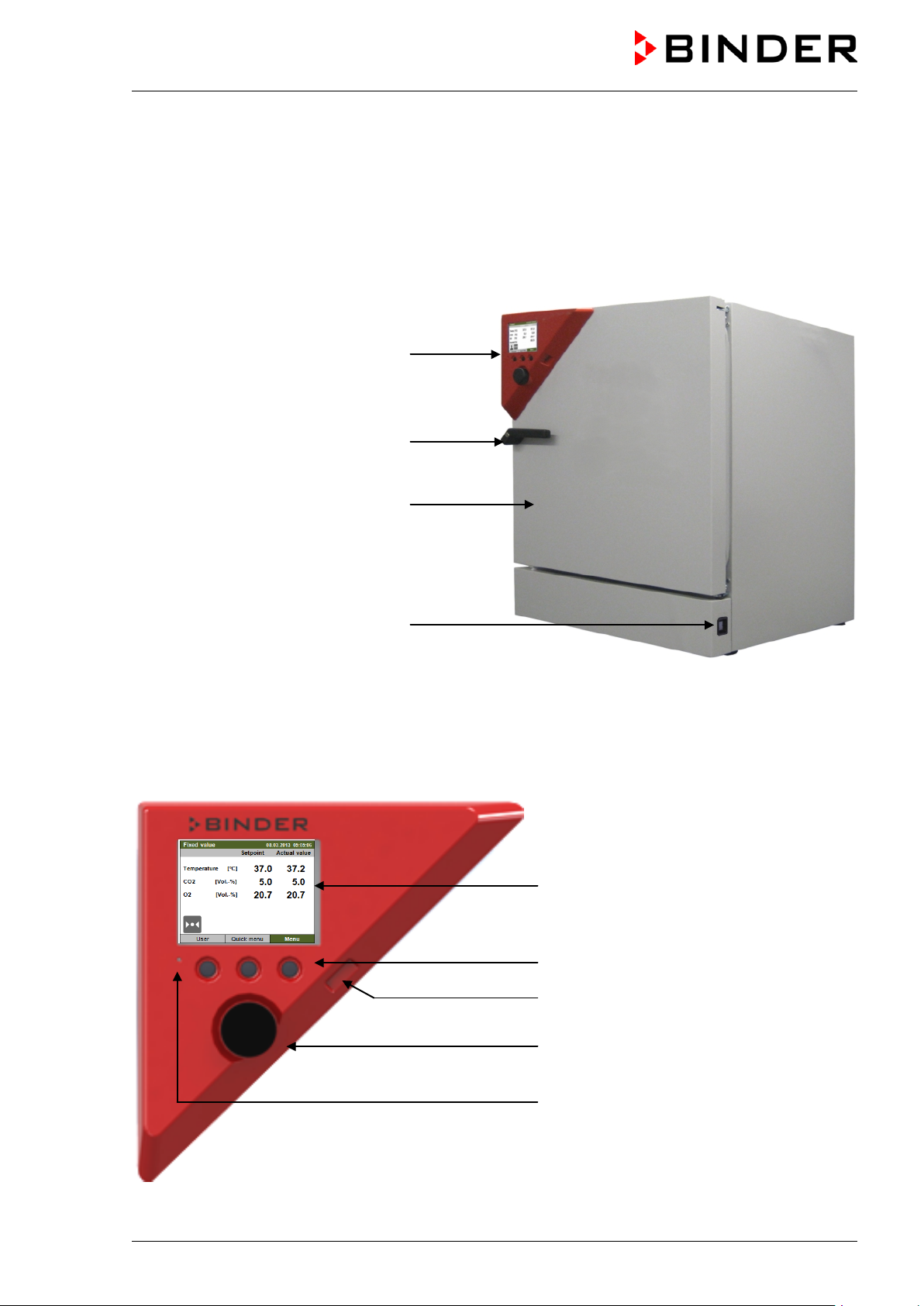
2.1 Chamber overview
Instrument panel with microprocessor
controller T4.12 and USB interface
Door handle
Chamber door
Main power switch
Figure 3: CO2 incubator CB (example: model CB 160)
2.2 Instrument panel
5,7" controller display
Context-sensitive buttons
USB interface
Operating button
Pilot lamp: ready for operation
Figure 4: Instrument panel with microprocess or controller T4.12 and USB interface
CB (E6.1) 07/2017 Page 17/145
Page 18
(A)
(B)
(C)
(D)
(
(G)
(F)
(E)
(
(I)
(
(
(
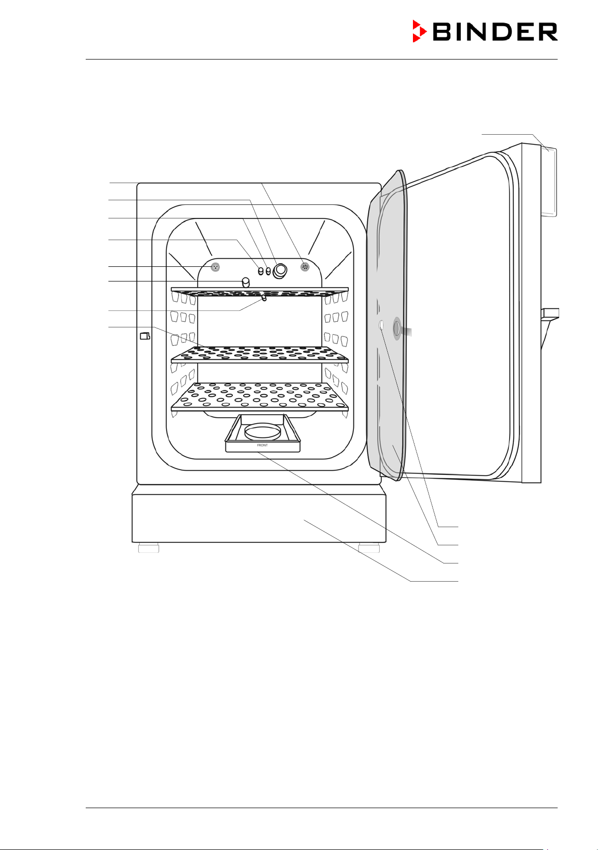
2.3 Inner chamber
D2)
H)
J)
K)
Figure 5: CB 160 with O
control and options
2
L)
CB (E6.1) 07/2017 Page 18/145
Page 19
(B)
(C)
(D)
(D2)
(G)
(F)
(E)
Figure 6: CB 160 / CB 220 with O
control and options
2
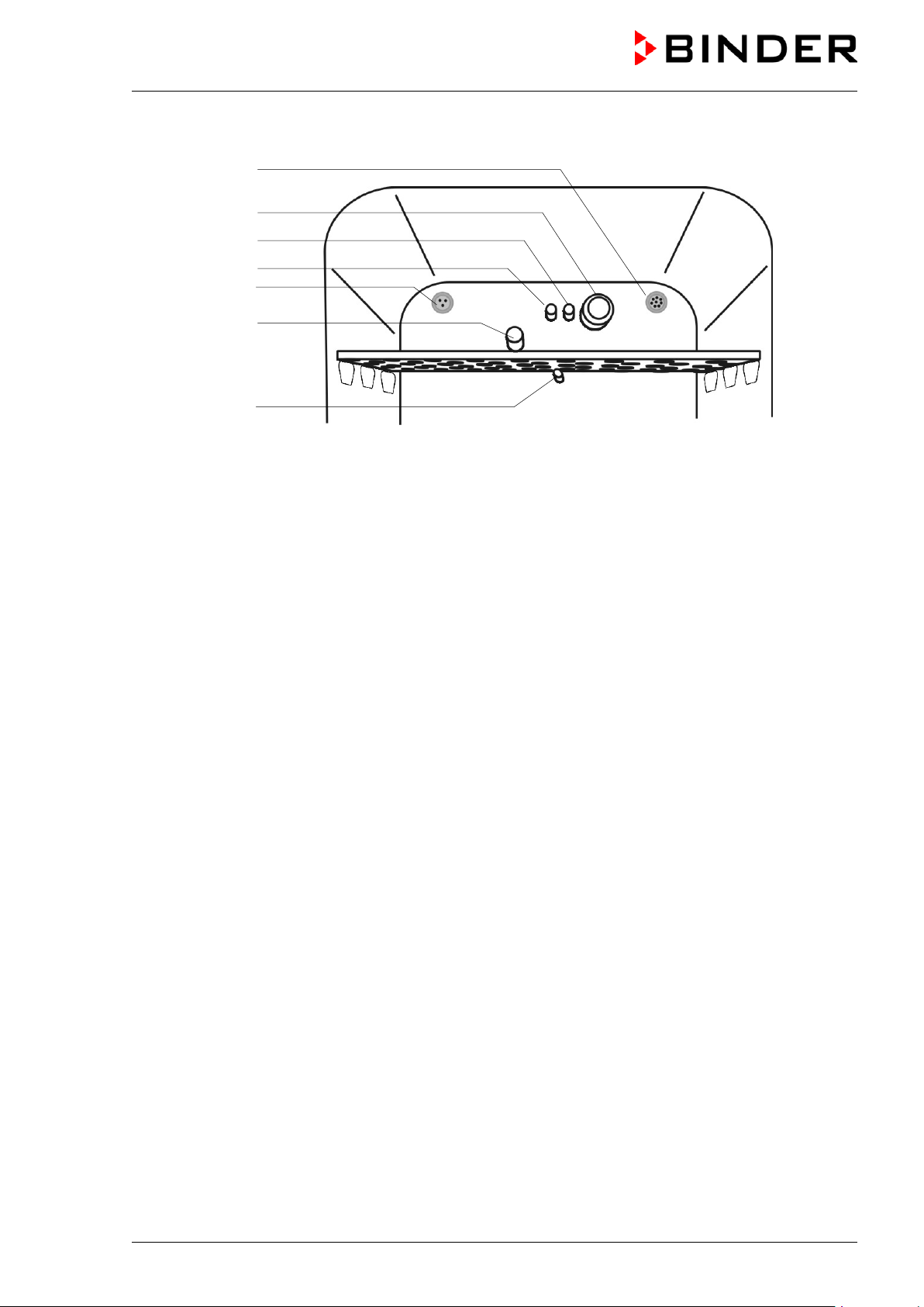
(A) Instrument panel with microprocessor controller T4.12, indicating temperature and CO
(chamber with O2 control)”
O
2
(B) Connection socket for extra-low voltage supply (option, chap. 15.6)
(C) CO
(D) Gas mixing head CO
(D2) Additional gas mixing head O
sensor
2
2
/ N2 (chamber with O2 control)
2
(E) Pt 100 temperature probe
(F) O
sensor (chamber with O2 control)
2
(G) Internal socket 230V (max. 3 A) (option, chap. 15.4)
(H) Perforated shelves, made of st ainl ess steel
(I) Measuring access port
(J) Inner glass doors
(K) Permadry™ water pans
(L) Lower housing cover
as well as
2
CB (E6.1) 07/2017 Page 19/145
Page 20
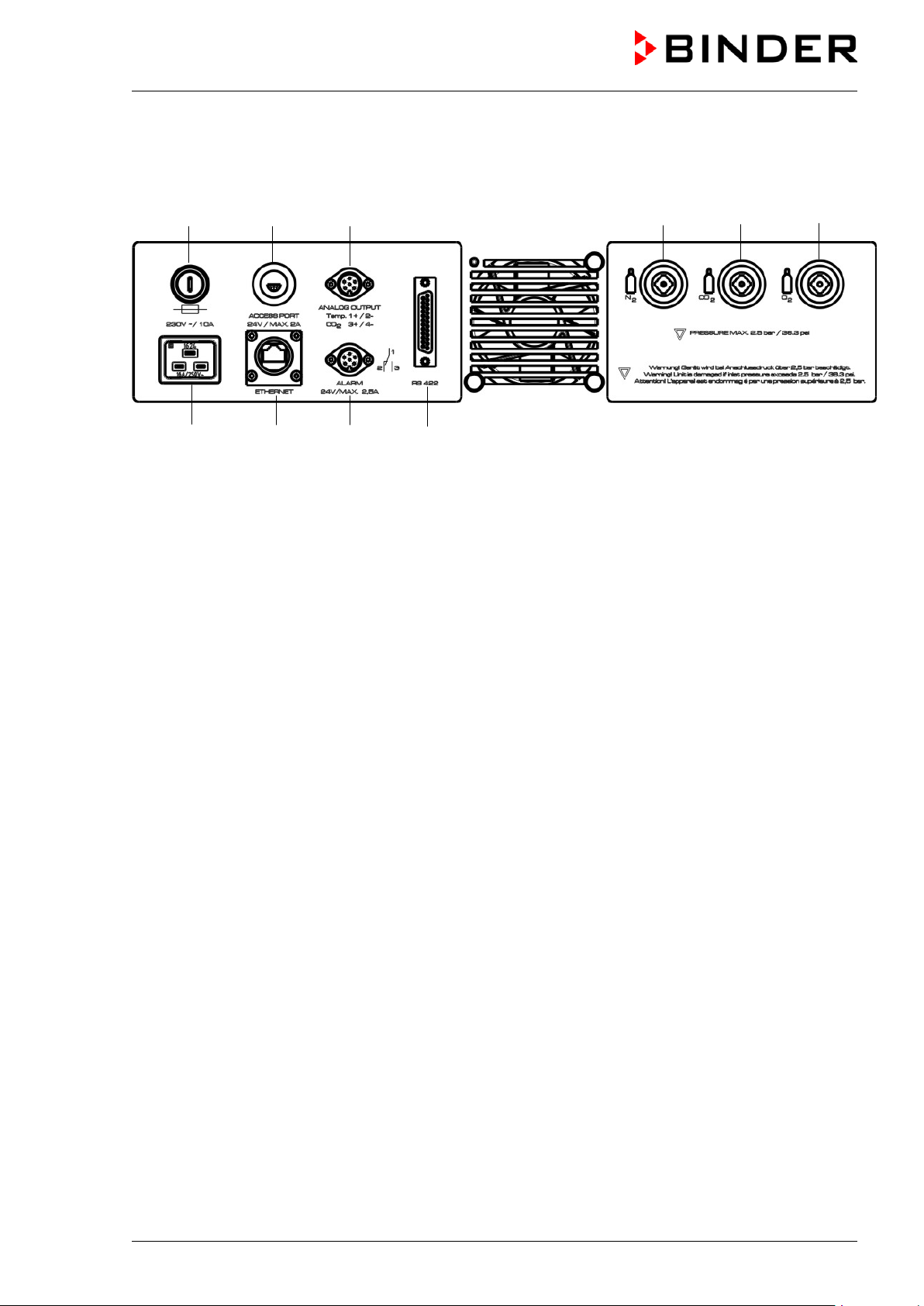
2.4 Control panel on the rear of t he chamber
(1) (2) (3) (6) (4) (5)
(7) (8) (9) (10)
Figure 7: Rear control panel CB with O
control and options
2
(1) Miniature fuse
(2) External socket for extra-low voltage supply (option for CB 160 / CB 220, chap. 15.6)
(3) DIN socket for analog outputs 4-20 mA (option, chap. 15.5)
(4) Quick acting closure socket for CO
(5) Quick acting closure socket for O
10 up to 95 vol.-% O
)
2
(6) Quick acting closure socket for N
2
(chamber with O2 control and optional alternative control range
2
(chamber with O2 control)
2
(7) Socket for IEC connector plug for power cable
(8) Ethernet interface for computer communication
(9) DIN-socket for zero-voltage relay alarm outputs
(10) RS 422 interface for computer communication ( option)
CB (E6.1) 07/2017 Page 20/145
Page 21
3. Completeness of delivery, transportation, storage, and
installation
3.1 Unpacking, and checking equipm ent and completeness of delivery
After unpacking, please check the chamber and its optional accessories, if any, based on the delivery
receipt for completeness and for transportation damage. Inform the carrier immediately if transportation
damage has occurred.
The final tests of the manufacturer may have caused traces of the shelves on the inner surfaces. This has
no impact on the function and performance of the chamber.
Please remove any transportation protection devices and adhesives in/on the chamber and on the doors
and remove the operating manuals and accessory equipment.
Remove any protective lamination sheet on the inner metal surfaces prior to commissioning.
CAUTION
Sliding or tilting of the chamber.
Damage to the chamber.
Risk of injury by lifting heavy loads.
Do NOT lift or transport the chamber using the doo r handle, the door or the lower
housing.
Lift the chamber from the pallet at the four lower corners with the aid of four people.
If you need to return the chamber, please use the original packing and observe the guidelines for safe
lifting and transportation (chap. 3.2).
For disposal of the transport packing, see chap. 20.1.
Note on second-hand chambers (Ex-Demo-Units):
Second-hand chambers are chambers that were used for a short time for tests or exhibitions. They are
thoroughly tested before resale. BINDER ensures that the chamber is technically sound and will work
flawlessly.
Second-hand chambers are marked with a sticker on the chamber door. Please remove the sticker before
commissioning the chamber.
3.2 Guidelines for safe lifting and t ransport ation
After operation, please observe the guidelines for temporary decommissioning (chap. 20.2). Empty the
Permadry™ water pan before moving the chamber. In case of any spilling of the contents, shut down the
chamber and dry it out carefully and completely.
CB (E6.1) 07/2017 Page 21/145
Page 22
CAUTION
Sliding or tilting of the chamber.
Damage to the chamber.
Risk of injury by lifting heavy loads.
Transport the chamber in its original packaging only.
For moving or shipping, secure the chamber with transport straps.
∅ Do NOT lift or transport the chamber using the door handle, the door or the lower
housing.
Lift the chamber at the four lower corners with the aid of 4 peopl e and place it on a
rolling pallet.
Move the chamber to the desired location and lif t it from the rolling pallet with the aid of
four people.
• Permissible ambient temperature range during transport: 10 °C / 14 °F to +60 °C / 140 °F.
You can order transport packing for moving or shipping purposes from BINDER service.
3.3 Storage
Intermediate storage of the chamber is possible in a closed and dry room. Observe the guidelines for
temporary decommissioning (chap. 20.2).
• Permissible ambient temperature range during storage: -10 °C / 14 °F to +60 °C / 140 °F.
• Permissible ambient humidity: max. 70 % r.H., non-condensing
When after storage in a cold location you transfer the chamber to its warmer installation site,
condensation may form. Before start-up, wait at least one hour until the chamber has attained ambient
temperature and is completely dry.
3.4 Location of installation and ambi ent conditions
Notes on the location of installation
Set up the chamber on a flat, even surface, free from vibration and in a well-ventilated, dry location. The
chambers are designed for setting up inside a building (indoor use).
Freestanding chamber are suitable for installation on tables or on the optionally available stand (height
200 mm / 0.5 ft). Note: The site of installation must be capable of supporting the chamber’s weight (see
technical data, chap.22.4).
Align the chamber using a spirit level to ensure even covering of the cell-cultures with the medium. For
this purpose, manually adjust the four chamber feet.
The chambers can be stacked on top of each other (two chambers maximum). For safe stacking that is
easy to maintain, use the original BINDER stacking stand (chap. 15.8.1) or the stacking adapter (chap.
15.8.2).
CAUTION
Sliding of stacked chamber.
Damage to the chambers.
When stacking, use rubber pads (Art. No. 8012-0376) for the feet of the upper
chamber.
To completely separate the chamber from the power supply, you must disconnect the power plug. Install
the chamber in a way that the power plug is ea sily accessible and can be easily pulled in case of danger.
For the user there is no risk of temporary ov ervoltages in the sense of EN 61010-1:2010.
CB (E6.1) 07/2017 Page 22/145
Page 23
CAUTION
In order to avoid contamination, never place the chamber directly on the floor.
Danger of overheating.
Damage to the chamber.
∅ Do NOT set up chambers in non-ventilated recesses.
Ensure sufficient ventilation for dispersa l of the heat.
Do not install or operate the chamber in potentially explosive areas.
DANGER
Explosion hazard.
Danger of death.
∅ Do NOT operate the chamber in pot entially explosive areas.
KEEP explosive dust or air-solvent mixtures AWAY from the vicinity of the chamber.
Ambient conditions
• Permissible ambient temperature range for operation: +18 °C / 64.4 °F to +30 °C / 86 °F
At elevated ambient temperature values, f l uct uations in temperature can occur.
• Ideal ambient temperature: at least 7 °C / 12.6 °F below the intended working temperature. E.g.,
working temperature 37 °C / 98.6 °F = ambient temperature 30 °C / 86 °F and lower. In the event of
working temperatures of less than 7 °C / 12.6 °F above the ambient temperature, the setpoint can be
exceeded.
The ambient temperature should not be substanti al ly higher than the indicated ambient
temperature of 22 ±3 °C / 71.6 ±5.4 °F to which the specified technical data relates. For other
ambient conditions, deviations from the indicated data are possible.
Avoid direct solar radiation on the chamber.
• Permissible ambient humidity: 70 % r.H. max., non-condensing.
• Installation height : max. 2000 m / 6561.7 ft above sea level.
• Wall distances: rear 100 mm / 3.94 in, sides 50 mm / 1.97 in.
CB (E6.1) 07/2017 Page 23/145
Page 24
Notes on handling carbon dioxide (CO
Carbon dioxide (CO
) in high concentrations is hazardous to health. It is colorless and almost odorless
2
and therefore practically imperceptible. Vent out any CO
or a suitable connection to an exhaust sy st em . We recommend installing a CO
)
2
gas that may escape via good room ventilation
2
warning system.
2
WARNING
High concentration of CO2 (> 4 Vol.-%).
Danger of death by suffocation.
Danger of poisoning.
∅ Do NOT set up chambers in non-ventilated recesses.
Ensure technical ventilation measures.
Observe the relevant regulations for handling CO
Observe the occupational exposure limit OEL for CO2 set by the national authorities (formerly
maximum permitted workplace concentration). Check compliance when operating all chambers located in
the room.
3
• OEL for Germany: 5000 ml/m
• CO
lost with each opening the door: about 16.4 g, i.e. 0.0084 cubic meters / 0.296 cubic feet (under
2
(ppm) = 0,5 Vol.-%
normal pressure)
• CO
lost during 12h at 5 vol.-% without opening the door: approx. < 2 g, i.e. 0.001 cubic meter / 0.035
2
cubic feet (under normal pressure 1013 mbar / 14.7 psi)
.
2
An example of how to evaluate laboratory volume and air change rate:
Question: Is an air change rate of 1/h sufficient for a lab with a volume of 100 cubic meters /
3,531.5 cubic feet with 10 incubators CB, opened 4 times per hour?
Calculation: CO
concentration = CO2 lost by opening the door, multiplied by 10 chambers,
2
multiplied by opening the door 4 times per hour, di vided by lab volume
0.0084 cubic meters x 10 x 4 div. 100 cubic meters = 0.00336, i.e. 0.336 % or 3360 ppm.
0.296 cubic feet x 10 x 4 div. 3,531.5 cubic feet = 0.00336, i.e. 0.336 % or 336 0 ppm.
Result: The maximum permissible value of 5000 ppm is not exceeded under these operation
conditions.
Even when CO
or systems operated with CO2 are handled carefully and appropriately, a residual risk
2
remains, which can lead to life-threatening situations under certain circumstances. Therefore we strongly
recommend continuous monitoring of CO
be ensured permanently that the maximum permissible occupational exposure limit OEL for CO
% CO
for Germany) is not exceeded.
2
concentration in the ambient air of the CO2 incubator. It must
2
(0.5 vol -
2
Chamber with O
Oxygen (O
2
control: Notes on handling oxygen (O2)
2
) is colorless and almost odorless and therefore practically imperceptible. It promotes burns,
which can proceed explosively. There is a fire hazard for flammable oxygenated materials, e.g. clothes
and hair. O
is heavier than air and may accumulate in low-lyin g areas.
2
WARNING
High concentration of O2 (> 21 % O2).
Fire and explosion hazard through contact of combustible materials with O
.
2
Risk of burns and other injuries.
∅ Do NOT set up chambers in non-ventilated recesses.
Ensure technical ventilation measures.
Observe the relevant regulations for handling O
.
2
CB (E6.1) 07/2017 Page 24/145
Page 25
t and necessary safety
all gas connections by checking them for leaks (e.g. with leak
parts which are
Strictest smoking ban and no ignition sources in areas where oxygen enrichment is
Make sure good ventilation of areas where oxygen enrichment is possible (location of the
enriched atmosphere must keep away
ventilate their clothes at least 15
Take appropriate measures to prevent oxygen enrichment and fire and explosion hazards in areas where
oxygen enrichment is possible.
General information for safe handling of oxygen:
• Make sure training of personnel on hazards of oxygen enrichmen
measures.
• Make sure adequate labeling of all oxygen equipment and facilities.
• Make sure gas tightness of
spray or diluted soap solution).
• Close the main valve of the source of oxygen after work when not using the chamber.
• Never lubricate O
equipment with oil or fat. Use only materials and spare
2
approved for use with oxygen.
• Regularly inspect fire extinguishers for proper condition.
• Set up emergency showers where oxygen enrichment is possible.
•
possible.
•
chamber and/or O2 cylinders.
• Persons who may have been in a possibly oxygenfrom ignition sources (flames, cigarettes, etc.) and
minutes.
• Always keep emergency routes free.
Chamber with O
Nitrogen (N
therefore practically imperceptible. Any N
control: Notes on handling nitrogen (N2)
2
) in high concentrations is hazardous to health. It is colorless and almost odorless and
2
gas that may escape must be safely led out via good room
2
ventilation or a suitable connection to an exhaust system.
WARNING
High concentration of N2.
Risk of death by suffocation.
∅ Do NOT set up chambers in non-ventilated recesses.
Ensure technical ventilation measures.
Observe the relevant regulations for handling N
.
2
CB (E6.1) 07/2017 Page 25/145
Page 26
CB 60
CB 160 / CB 220
4. Installation and connections
4.1 Shelves
You can put the shelves in different positions at the line of channel beads in the inner chamber. Hold the
shelf straight and then insert it so it will go smoothl y inside the chamber.
Permitted shelf loads:
Maximum load of one single shelf: 10 kg / 22 lb
Maximum total load of all shelves: 30 kg / 66 lb
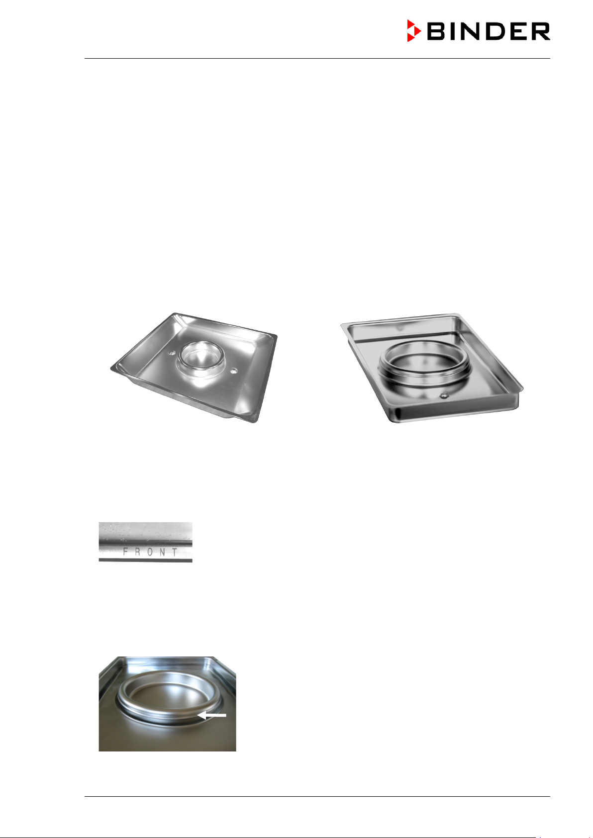
4.2 Permadry™ water pan
The Permadry™ system developed by BINDER is an effective and easy to handle system that ensures
high humidity inside the chamber without any condensation forming on the inner surfaces. The
Permadry™ water pan consists of two pans in which the outer one is heated and the inner one cooled.
With the slight difference of temperature caused by that cooling, the central pan is the specific point for
condensation of the surplus humidity. Therefo re, all other inner surfaces remain dry.
Figure 8: Permadry™ water pan
• Put the Permadry™ water pan on the bottom of the inner chamber in a way that both notches lock into
place.
• The front side of the Permadry™ water pan is marked “FRONT”.
Figure 9: Letters “FRONT” indicating the front of the Permadry™ water pan
• Please make sure that the Permadry™ water pan has firm contact to the inner chamber bottom and
rests tightly on it.
• Fill only the outer pan with distilled, sterilized water up to the filling level marking on the edge of the
inner pan.
Maximum filling quantity of the outer pan: CB 60: approx. 0.7 liters, CB 160 and CB220): approx.
2 liters.
Figure 10: Filling height line of the outer basin CB 160 / CB 220
CB (E6.1) 07/2017 Page 26/145
Page 27
• We recommend cleaning and refilling the pans 2 to 3 times a week. For evacuation, remove the
Permadry™ water pan.
• We recommend using distilled, sterile water to achieve optimum growth results. Any corrosive damage
that may arise following the use of water of different quality or by additives is excluded from the liability
agreement.
• If required, you can add microbiologically inhibiting substances such as copper chips, copper sulfate
or ethylene diamine tetra-vinegar acid (EDTA) in a concentration of 1 to 5 mmol/l.
Empty the Permadry™ water pan before moving the chamber. In case of the contents spilling,
immediately shut down the chamber and dry it careful ly and completely.
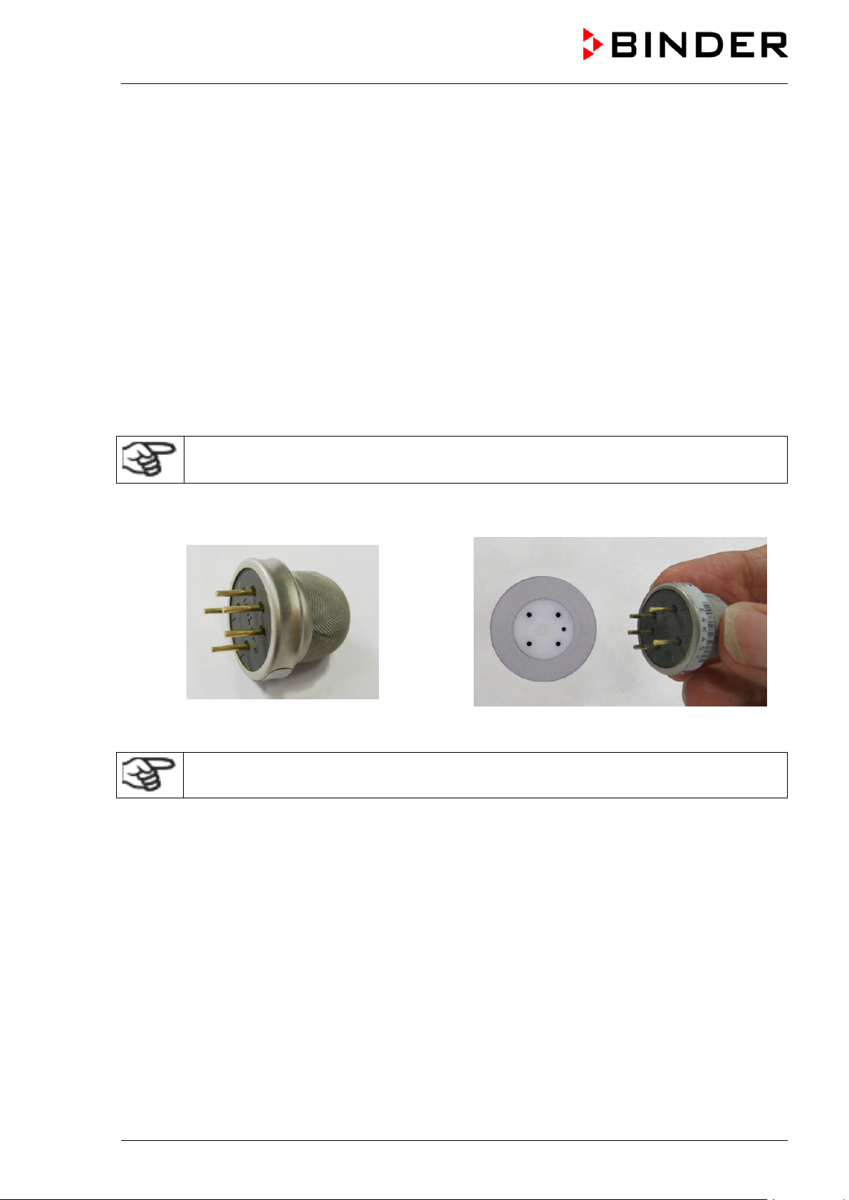
4.3 Connecting the O2 sensor (chamber with O2 control)
The O2 sensor is supplied with the chamber in a separate package.
Connect or remove the O2 sensor only when the chamber is turned off.
Open the door of the inner chamber and plug the O2 sensor (F) into the left connection socket located in
the upper part of the rear of the inner chamber. P ay attention to the correct positioning of the pins.
Figure 11: O2 sensor Figure 12: Connecting the O2 sensor
The O2 sensor must be plugged in during a hot-air sterilization.
CB (E6.1) 07/2017 Page 27/145
Page 28
Always close the valve even with apparently empty cylinders; screw on the cap when not in
4.4 Gas connections
General information for safe handling of gas cy l i nders:
• Store and use gas cylinders only in well ventilated areas.
• Open the gas cylinder valve slowly to avoid pressure surges.
• Secure gas cylinders during storage and use against falling (chaining).
• Transport gas cylinders with a cylinder cart, do not carry, roll, or throw them.
•
use. Return gas cylinders with the valve closed.
• Do not open gas cylinders by force. Mark them when damaged.
• Protect gas cylinders against fire, e.g. do not store together with flammable liquids.
• Observe relevant regulations for dealing with gas cylinders.
Secure the gas cylinder against falling and other m echanical damage.
WARNING
Safety valve tearing off.
Sudden release of the stored pressure energy.
Risk of injury.
Secure gas cylinders against falling (chaining).
Transport gas cylinders with a cylinder cart.
The valve of the gas cylinder always must be clo sed before screwing on or unscrewing the gas hose.
WARNING
Opening the cylinder valve when the cylinder is not connected.
Sudden release of the stored pressure energy.
Risk of injury.
Close the gas cylinder valve before connecting or removing the gas hose.
After connecting the gas cylinder, check all gas connections for leaks (e.g. with leak spray or
diluted soap solution).
CB (E6.1) 07/2017 Page 28/145
Page 29
4.4.1 Connection of the CO2 gas cylinder
Carbon dioxide (CO2) in high concentrations is hazardous to health. It is colorless and almost odorless
and therefore practically imperceptible. Vent out any CO
or a suitable connection to an exhaust sy st em . We recommend installing a CO
High concentration of CO2 (> 4 Vol.-%).
Risk of death by suffocation.
Danger of poisoning.
∅ Do NOT set up chambers in non-ventilated recesses.
Ensure technical ventilation measures.
Observe the relevant regulations for handling CO
The CO2 gas necessary for operation must have a t echnical grade of 99.5 %.
The gas connections must be established by quali fied personnel who are trained in handling
the respective gases and familiar with the required safety measures.
gas that may escape via good room ventilation
2
WARNING
2
.
warning system.
2
The following steps are required:
Ensuring the correct CO
output pressure
2
A gas supply pressure above 2.5 bar / 36 psi will result in chamber damage.
Use a pressure reducer and make sure to avoid any excessive outlet pressure when connecting the
gas hose to the chamber.
The real outlet pressure of gas cylinders, sets of gas cylinders or central gas supplies am on the
second manometer must not exceed 2.5 bar / 36 psi.
CAUTION
Excessive outlet pressure > 2.5 bar / 36 psi.
Damage to the chamber.
∅ The outlet pressure must NOT exceed the indicated value of 2.5 bar / 36 psi.
Before connecting, check the outlet pressure on the pressure reducer of the
cylinder.
Adjust the outlet pressure to 2.0 bar / 29 psi above the ambient pressure.
Observe the correct outlet pressure also when replacing t he gas cylinders.
Establishing the connection to the chamber
Connect the supplied gas hose (internal diameter 6 mm / 0.24 inches) to the pressure reducer of the
gas cylinders or central gas supply and secure the connection with the supplied hose clamp.
Connect the pre-assembled hose nozzle of the gas hose to the quick acting closure socket (4) DN 6
on the chamber rear, as described in chap. 4.4.4.
Leak test
After connecting the gas cylinder, check all gas connections for leaks (e.g. with leak spray or diluted
soap solution).
CB (E6.1) 07/2017 Page 29/145
Page 30
cylinder or disconnect the gas supply (by pulling off the gas hose)
CAUTION
The recovery times of the gas concentrations inside the chamber after opening the door are
indicated in the technical data (chap. 22.4) and refer to a connecti on pressure of 2.0 bar / 29
psi. Decreasing supply pressure will result in l onger recovery times.
Conversion table for gas inlet pressures, bar – psi, see chap. 22.8.
4.4.2 Connection of the O2 gas cylinder (chamber with O2 control and optional
alternative control range 10 up to 95 vol.-% O
Note: Do not connect the O2
when operating at setpoints below 19 vol.-% O2.
Oxygen (O2) is colorless and almost odorless and therefore practically imperceptible. It promotes burns,
which can proceed explosively. There is a fire hazard for flammable oxygenated materials, e.g. clothes
and hair. O
is heavier than air and may accumulate in low-lyin g areas.
2
)
2
WARNUNG
High concentration of O2 (> 21 % O2).
Fire and explosion hazard through contact of combustible materials with O
Risk of burns and other injuries.
∅ Do NOT set up chambers in non-ventilated recesses.
Ensure technical ventilation measures.
Observe the relevant regulations for handling O
.
2
The O2 gas necessary for operation must have a t echnical grade of 99.5 %.
.
2
The gas connections must be established by quali fied personnel who are trained in handling
the respective gases and familiar with the required safety measures.
The following steps are required:
Ensuring the correct O
output pressure
2
A gas supply pressure above 2.5 bar / 36 psi will result in chamber damage.
Use a pressure reducer and make sure to avoid any excessive outlet pressure when connecting the
gas hose to the chamber.
The real outlet pressure of gas cylinders, sets of gas cylinders or central gas supplies am on the
second manometer must not exceed 2.5 bar / 36 psi.
Excessive outlet pressure > 2.5 bar / 36 psi.
Damage to the chamber.
∅ The outlet pressure must NOT exceed the indicated value of 2.5 bar / 36 psi.
Before connecting, check the outlet pressure on the pressure reducer of the
cylinder.
Adjust the outlet pressure to 2.0 bar / 29 psi above the ambient pressure.
Observe the correct outlet pressure also when replacing t he gas cylinders.
CB (E6.1) 07/2017 Page 30/145
Page 31

Establishing the connection to the chamber
Connect the supplied gas hose (internal diameter 6 mm / 0.24 inches) to the pressure reducer of the
gas cylinders or central gas supply and secure the connection with the supplied hose clamp.
Connect the pre-assembled hose nozzle of the gas hose to the quick acting closure socket (5) DN 6
on the chamber rear, as described in chap. 4.4.4.
Leak test
After connecting the gas cylinder, check all gas connections for leaks (e.g. with leak spray or diluted
soap solution).
The recovery times of the gas concentrations inside the chamber after opening the door are
indicated in the technical data (chap. 22.4) and refer to a connecti on pressure of 2.0 bar / 29
psi. Decreasing supply pressure will result in longer recovery t i m es.
Conversion table for gas inlet pressures, bar – psi, see chap. 22.8.
4.4.3 Connection of the N2 gas cylinder (chamber with O2 control)
Nitrogen (N2) in high concentrations is hazardous to health. It is colorless and almost odorless and
therefore practically imperceptible. Any N
ventilation or a suitable connection to an exhaust system.
gas that may escape must be safely led out via good room
2
WARNING
High concentration of N2.
Risk of death by suffocation.
∅ Do NOT set up chambers in non-ventilated recesses.
Ensure technical ventilation measures.
Observe the relevant regulations for handling N
The N2 gas necessary for operation must have a t echnical grade of 99.5 %.
The gas connections must be established by quali fied personnel who are trained in handling
the respective gases and familiar with the required safety measures.
The following steps are required:
Ensuring the correct N
output pressure
2
A gas supply pressure above 2.5 bar / 36 psi will result in chamber damage.
Use a pressure reducer and make sure to avoid any excessive outlet pressure when connecting the
gas hose to the chamber.
The real outlet pressure of gas cylinders, sets of gas cylinders or central gas supplies am on the
second manometer must not exceed 2.5 bar / 36 psi.
.
2
CB (E6.1) 07/2017 Page 31/145
Page 32

CAUTION
Excessive outlet pressure > 2.5 bar / 36 psi.
Damage to the chamber.
∅ The outlet pressure must NOT exceed the indicated value of 2.5 bar / 36 psi.
Before connecting, check the outlet pressure on the pressure reducer of the
cylinder.
Adjust the outlet pressure to 2.0 bar / 29 psi above the ambient pressure.
Observe the correct outlet pressure also when repla cing the gas cylinders.
Establishing the connection to the chamber
Connect the supplied gas hose (internal diameter 6 mm / 0.24 inches) to the pressure reducer of the
gas cylinders or central gas supply and secure the connection with the supplied hose clamp.
Connect the pre-assembled hose nozzle of the gas hose to the quick acting closure socket (6) DN 6
on the chamber rear, as described in chap. 4.4.4.
Leak test
After connecting the gas cylinder, check all gas connections for leaks (e.g. with leak spray or diluted
soap solution).
The recovery times of the gas concentrations inside the chamber after opening the door are
indicated in the technical data (chap. 22.4) and refer to a connecti on pressure of 2.0 bar / 29
psi. Decreasing supply pressure will result i n l onger recovery times.
Conversion table for gas inlet pressures, bar – psi, see chap. 22.8.
4.4.4 Connecting the gas hose to the chamber rear (for CO2, O2, N2)
The procedure of connecting the gas hose to the chamber rear is the same for any gas connection. All
quick acting closure sockets (CO
and optional alternative control range 10 up to 95 vol.-% O
, N2 on chamber with O2 control, and O2 on chamber with O2 control
2
) are degreased and supplied with a FKM
2
gasket.
Note for chambers with O
connection (chamber with O
control: The quick acting closure socket and the hose nozzle for the O2
2
control) must be degreased.
2
WARNING
Fire and explosion hazard through contact of fat with O2.
Risk of burns and other injuries.
∅ All connection parts for the O
connection must be degreased.
2
The gas hose, which will be used to establish the connection to a gas cylinder, is already attached to the
hose nozzle and secured by a hose clamp. Plug the hose nozzle into the corresponding quick acting
closure socket (a) located at the rear of the chamber. This quick acting closure socket is closed by a
rubber cover (b).
Only use the supplied hose nozzle to connect to t he qui ck acting closure socket.
Otherwise, the quick acting closure socket may leak, and/or it may become impossible to
connect the original hose nozzle. In this case, pl ease contact BINDER Service.
CB (E6.1) 07/2017 Page 32/145
Page 33

Gas cylinder connection kits are available for CO2 ( Art. No. 8012-0014), O2
rs for cylinder pressure (high pressure
assembled hose nozzle for quick acting
(a)
(c)
(b)
Remove the rubber cover (b) by pulling it of f.
Chamber rear
Figure 13: Connecting the hose lead to the gas cylinder
Now fit the hose nozzle (c) in the quick acting closure socket. To remove the connection, pull the hose
nozzle off the quick acting closure socket.
4.4.5 Gas cylinder connection kits (option)
(Art. No. 8012-0015) and N2 (Art. No. 8012-0016).
The connection kit includes the following parts for connecting a gas cylinder
to the CO
• Pressure reducer with manomete
gauge) and outlet pressure (low pressure gaug e)
• 5 m pressure hose with preclosure socket
• 1 hose clamp to connect the gas hose to the pressure reducer
Figure 14: Gas cylinder connection kit
Instructions 7001-0249 included with the connection kit describe connecting and setting the
gas cylinder connection kit.
incubator:
2
Excessive outlet pressure > 2.5 bar / 36 psi.
Damage to the chamber.
∅ The outlet pressure must NOT exceed the indicated value of 2.5 bar / 36 psi.
Before connecting, check the outlet pressure on the pressure reducer of the cylinder.
Adjust the outlet pressure to 2.0 bar / 29 psi above the ambient pressure.
The gas connections must be established by quali fied personnel who are trained in handling
the respective gases and familiar with the required safety measures.
CB (E6.1) 07/2017 Page 33/145
CAUTION
Page 34

4.5 Electrical connection
The chambers are supplied ready for connection. They come with an IEC connec tor plug.
Model (including
chambers with O2
control and/or
divided inner door)
Art. No.
(x = 0 or 1)
Power plug
Voltage
+/-10 %
Power
frequency
Chamber
fuse
CB 60
CB 60-UL
CB 160
CB 160-UL
CB 220
CB 220-UL
9x40-0088
9x40-0090
9x40-0089
9x40-0091
9x40-0092
9x40-0100
9x40-0094
9x40-0102
9x40-0093
9x40-0101
9x40-0095
9x40-0103
9x40-0096
9x40-0108
9x40-0098
9x40-0110
9x40-0097
9x40-0109
9x40-0099
9x40-0111
Shock-proof plug 200-240 V (1N~) 50/60 Hz 10 A
NEMA 5-15P 100-120 V (1N~) 50/60 Hz 16 A
Shock-proof plug 200-240 V (1N~) 50/60 Hz 10 A
NEMA 5-20P 100-120 V (1N~) 50/60 Hz 16 A
Shock-proof plug 200-240 V (1N~) 50/60 Hz 10 A
NEMA 5-20P 100-120 V (1N~) 50/60 Hz 16 A
• The domestic socket must also provide a protective conductor. Make sure that the connection of the
protective conductor of the domestic installations to the chamber’s protective conductor meets the
latest technology. The protective conduc tors of the socket and plug must be compatible!
• Prior to connection and start-up, check the power supply voltage. Compare the values to the specified
data located on the chamber’s type plate (left chamber side, bottom right-hand, see chap. 1.4). We
recommend the use of a residual current cir cuit breaker.
• When connecting, please observe the regulations specified by the local electricity supply company as
well as the VDE directives (for Germany).
• Pollution degree (acc. to IEC 61010-1): 2
• Over-voltage category (acc. to IEC 61010-1): II
CAUTION
Danger of incorrect power supply voltage.
Damage to the equipment.
Check the power supply voltage before connect i on and start-up.
Compare the power supply voltage with the data indicated on the type plate.
See also electrical data (chap. 22.4).
CB (E6.1) 07/2017 Page 34/145
Page 35

divided inner door, with
elongated holes to align
To completely separate the chamber from the power supply, you must disconnect the power
plug. Install the chamber in a way that the power plug is easily accessible and can be easily
pulled in case of danger.
4.6 Handling and aligning the divided inner door, gas proof (optional
equipment)
Rubber profile gasket of
individual glass door of
the divided inner door
Hinge of the set-in
the inner door
Measuring access port
Figure 15: Divided inner door, gas proof, for CB 160
• Pull the handles to open each of the individual glass doors. Do not press too hard while closing them
to avoid pushing the doors through the gasket i nto the inner chamber.
• The rubber profile gaskets of the individual glass doors are easy to replace.
• If the divided inner door is not in an aligned position, fasten the hinge screws in the elongated holes of
the hinge to align it. Align the door and operate the locking smoothly.
CB (E6.1) 07/2017 Page 35/145
Page 36

5. Start up
After connecting the supply lines (chap. 4.5) turn on the chamber by the main power switch. The pilot
lamp shows the chamber is ready for operation.
Observe a delay time of about 30s between turning Off and On again. Otherwise an
initialization problem may occur.
Note that the chamber is in stand-by mode when the main power switch has been turned on and yet the
controller display is dark. Turn on the chamber by pressing any controller button.
Warming chambers may release odors in the first few days after commissioning. This is not a quality
defect. To reduce odors quickly we recommend heating up the chamber to its nominal temperature for
one day and in a well-ventilated location.
WARNING: If customer should use a BINDER cham ber running in non-supervised continuous
operation, we strongly recommend in case of i nclusion of irrecoverable specimen or samples
to split such specimen or samples and store them in at least two chambers, if this is feasible.
After chamber startup this symbol and the message window “Power supply was interrupted.”
appear in the controller display. Confirm with OK to close the window and make the icon
disappear.
5.1 Equilibration ti m e
Temperature: Equilibration time is approx. 1 hour.
CO
: After approx. 5 minutes, the CO2 concentration equilibrates automatically to the pre-set value of 5
2
vol.-% CO
O
(chamber with O2 control): After a delay of 10 minutes, the ambient oxygen concentration of approx.
2
20.7 vol.-% is displayed. During the first 10 minutes, O
.
2
control is not defined. Then O2 is regulated to the
2
displayed setpoint value of 20.7 vol.-%.
5.2 Factory settings
The chamber is supplied with the following basic preset parameter s:
• Temperature setpoint 37 °C / 98.6°F
• CO
• O
• Safety controller class 3.1 38.5 °C / 101.3°F
• Sterilization tem perature 187.5 °C / 369.5°F
concentration 5 vol.-%
2
concentration (chamber with O2 control) 20.7 vol.-%
2
• Audible alarm signal ( buzzer) turned on
The set temperature determines the target working temperature in the inner chamber, i.e. set value 37 °C
/ 98.6°F = target working temperature 37 °C / 98.6°F. The same is valid for the CO
(chamber with O
control). For the hot-air sterilization, the set value is 187.5 °C / 369.5°F and cannot be
2
and O2 concentration
2
changed.
As long as there is a difference between the actual and set value shown in the display,
adequate operation of the chamber is not guara nteed.
CB (E6.1) 07/2017 Page 36/145
Page 37

6. Functional overview of the T4.12 chamber controller
The T4.12 chamber controller controls the following values inside the chamber:
• Temperature in °C (range by 7 °C / 12.6 °F above ambi ent temperature up to +60 °C / 140 °F)
• Carbon dioxide conc entration in vol.-% (range 0 vol.-% up to 20 vol.-%)
Chamber with O
• Oxygen concentration i n vol.-% (range 0.2 vol.-% up to 95 vol.-%)
control in addition:
2
You can enter the desired setpoint values in fixed value operating mode in the display controller. The
controller also offers various notifications and alarm messages with visual and audible indication, a trace
file and remote alarms via e -mail. Programming can be done directly through the keypad of the controller
or graphically through the software APT-COM™ 3 DataControlSystem (option, chap. 15.1) specially
developed by BINDER.
Temperature values
values
CO
2
values
O
2
Actual values
Setpoint values
Icons:
Controller operating in “fixed
value” operating mode
Figure 16: T4.12 microprocessor controller, initial view in “Fixed value” controller mode
(sample values, chamber with O
control)
2
CB (E6.1) 07/2017 Page 37/145
Page 38

Fixed value
Setpoint
Actual value
37.0
37.2
5.0
5.0
20.7
20.7
Menu
Fixed value
..\ Menu
Controller mode
Event list
Alarms
Setpoints
Safety controller
Import/Export
Hot-air sterilization
Humidity control
6.1 Menu structure
08.03.2013 05:05:06
Temperature [°C]
CO2 [Vol.-%]
O2 [Vol.-%]
User Quick menu
From the Initial view you have access to different menus using the menu buttons “User”, “Quick menu”, or
“Menu”. From there you can access the desired control functions. To do this, select the function by
turning the operating button and press the oper ating button to confirm the selection.
In any menu, you can return to the previous display pressing the "Close" button or to the initial view with
the "Home" button.
Depending on the logged-in user or administrator, the available menu functions may vary. These
instructions present the functions which are available to the logged-in administrator.
6.1.1 General menu
The general menu provides access to all setting functions of the controller, a graphical display of the
measured values, and the possibility to read and give out data via the USB interface. In addition,
supporting functions like a settings wizard or a contact page are available.
Initial view (sample values, chamber with O2
control).
Press the desired menu button.
08.03.2013 05:05:06
General menu
Close Home
Turn the operating button to see additional menu items.
CB (E6.1) 07/2017 Page 38/145
Page 39

Fixed value
..\ Menu
Settings
Measurement chart
Interior socket (optional)
Sensor adjustment
Service contact
System information
Fixed value
..\ Quick menu
Measurement chart
Active alarms
Temperature setpoint
CO2 setpoint
O2 setpoint
Safety controller setpoint
Hot-air sterilization
08.03.2013 05:05:06
General menu (next page)
Close Home
Controller mode
Switching between the operating modes “control of f” or “fixed value”, chap.
6.2.1
Event list Display of status information and errors, chap. 12
Alarms
Setpoints
Safety controller
Import/Export
Hot-air sterilization
Humidity control
Settings
Measurement chart
Interior socket (optional)
Sensor adjustment
Service contact
System information
Alarm settings, chap. 11.5
Setpoint entry, chap. 7.4
Setting the safety controller, chap. 14.2
Data transfer via USB interface, chap. 10
Performing a hot-air sterilization at 180 °C / 356 °F, chap. 18.3
Setting the humidity control of the Permadry™ sy stem, chap.6.4
General controller settings, chap. 9
Graphical display of the measured values, chap. 13
Turning on / off the interior socket voltage (opt i on), chap. 6.5
Adjustment menu for single-point and two-point adjustments (for Service)
Service information
Chamber information (model, name, serial no., firmware etc.)
6.1.2 Quick menu
The Quick menu provides fast access to frequently used functions.
Close Home
CB (E6.1) 07/2017 Page 39/145
08.03.2013 05:05:06
“Quick menu”.
(item “O
setpoint” only coming with
2
chamber with O
control)
2
Page 40

Fixed value
..\ User
Key lock
Show event list
Measurement chart Graphical display of the measured values, chap. 13
Active alarms Alarm settings, chap. 11.5
Temperature setpoint Temperature setpoint entry, chap. 7.3
CO2 setpoint CO2 setpoint entry, chap. 7.3
O2 setpoint O2 setpoint, chap. 7.3
Safety controller setpoint Setting the safety controller setpoint, chap. 14.2.2
Hot-air sterilization Performing a hot-air sterilization at 180 °C / 356 °F, chap. 18.3
6.1.3 User menu
The user menu includes the key lock function, and pr ovides quick access to the event list.
The key lock function serves to block the access to the controller. An overview of logon, logoff, and other
events is given in the event list.
08.03.2013 05:05:06
“User” menu
Close Home
Key lock Configuring the key lo ck function, chap. 8
Show event list Displaying the event list, chap. 12
CB (E6.1) 07/2017 Page 40/145
Page 41

Fixed value
..\ Menu
Controller mode
Event list
Alarms
Setpoints
Safety controller
Import/Export
Hot-air sterilization
Humidity control
Fixed value
..\ Controller mode
Control off
Fixed value
O2 control
6.2 Operating modes
In the “control off” mode (chap. 6.2.1), the controller is non-functional and displays only the actual
values. There is no heating or refrigeration and no inlet of CO
temperature approximates the ambient val ue.
You can enter the desired setpoint values in “fixed value” mode (chap. 7). The controller then operates
as a fixed-point control, i.e., it reaches a nd m ai ntains the defined setpoints until the next manual change.
6.2.1 Activating the “control off” mode or change to “fixed value” operating mode
To select the “control off” or “fixed value” operating m ode, go to Menu > Controller mode
08.03.2013 05:05:06
General menu.
Select “Controller Mode”
and press the operating button.
or O2 (chamber with O2 control). The
2
Close Home
08.03.2013 05:05:06
Close Home
Submenu “Controller Mode”.
Select the desired controller mode
“Control off” or “Fixed value”
and press the operating button.
CB (E6.1) 07/2017 Page 41/145
Page 42

Control off
..\ Menu
Controller mode
Event list
Alarms
Setpoints
Safety controller
Import/Export
Hot-air sterilization
Humidity control
Control off
Setpoint
Actual value
22.2
0.3
0.5
08.03.2013 05:05:06
General menu.
The controller mode “Fixed value” or “Control off” is
indicated in the display headline.
Close Home
Go back to the initial view with “Home”.
08.03.2013 05:05:06
Temperature [°C]
CO2 [Vol.-%]
O2 [Vol.-%]
User Quick menu
The controller is non-functional, i.e., there is no heating or CO2 entry or O2 entry (chamber with O2
control).
Menu
Initial view in “Control off” mode (sample v al ues)
CB (E6.1) 07/2017 Page 42/145
Page 43

Hyperoxic range
(>22 vol.-% O2)
Hypoxic range
(<20 vol.-% O2)
Hyperoxic and
hypoxic ranges
6.3 Deactivating the O2 control and O2/N2 pressure alarms (chamber with O2
control)
6.3.1 Required gas supply of the chamber with O2 control
In the chamber with O2 control, cell growth can be additionally influenced by a variable oxygen content.
Depending on the required range of O2 concentr ation, the type of gas which is required may vary:
• Hyperoxic range (> 22 vol.-% O
As compared to the ambient air (O
increased, no nitrogen is required for the O
cylinder. You can deactivate the N
)
2
concentration of 20.9 vol.-%) only the O2 concentration needs to be
2
control. Therefore, it is not necessary to connect a N2
pressure alarm in the menu “Menu > Controller mode > O2 control”
2
2
(chap. 6.3.2).
• Hypoxic range (< 20 Vol.-% O
As compared to the ambient air (O
be increased, no oxygen is required for the O
cylinder. You can deactivate the O
)
2
concentration of 20.9 vol.-%) only the N2 concentration needs to
2
pressure alarm in the menu “Menu > Controller mode > O2
2
control. Therefore, it is not necessary to connect an O2
2
control” (chap. 6.3.2).
• Hyperoxic and hypoxic range or range from 20 vol.-% O
and O2 are required for O2 control. It is necessary to connect all gas sup pl i es.
N
2
• Operation without O
You can deactivate the O
With this setting, no alarm messages for O
control
2
control in the menu “Menu > Controller mode > O2 control” (chap. 6.3.2).
2
and N2 (pressure or concentration) will be issued.
2
up to 22 vol.-% O2
2
Since neither nitrogen nor oxygen are required, it is not necessary to connect an O
and N2 pressure alarms will be issued with deactivated O2 control.
O
2
The zero-voltage relay alarm contact (chap. 11.6) for messages of deviation of the O
will also not be triggered.
or N2 cylinder. No
2
concentration
2
Overview
No O2 control
off
O2 control (with O2
concentration alarm)
active active active
Connection of O2 cylinder connected not connected connected not connected
off
O2 pressure alarm active
active off
Connection of N2 cylinder not connected connected connected not connected
off
N2 pressure alarm
active active off
CB (E6.1) 07/2017 Page 43/145
Page 44

Fixed value
..\ O2 control
O2 control: On
O2 pressure alarm: On
N2 pressure alarm: On
Fixed value
Setpoint
Actual value
37.0
37.2
5.0
5.0
20.9
Menu
Fixed value
Setpoint
Actual value
37.0
37.2
5.0
5.0
20.9
Menu
6.3.2 Activating / deactivating the O2 control and O2 / N2 pressure alarms
To activate or deactivate the O2 control and O2 / N2 pressure alarms, go to
Menu > Controller mode > O2 control
08.03.2013 05:05:06
Close Home
Go back to the initial view with “Home”.
08.03.2013 05:05:06
Temperature [°C]
CO2 [Vol.-%]
O2 [Vol.-%]
Submenu “O2 control”.
The current settings are displayed.
To change the settings, press the operating button.
The modified settings are displayed
“O2 control: On” = O
“O2 control: Off” = O
“O2 pressure alarm: On” or “N2 pressure alarm: O n”
= the corresponding pressure alarm is activated.
“O2 pressure alarm: Off” or “N2 pressure alarm: Off”
= the corresponding pressure alarm is deactiv ated.
Initial view with deactivated O2 control
(sample values).
Also the pressure alarms for O
deactivated.
control is active.
2
control is deactivated.
2
and N2 are
2
User Quick menu
To enter the O2 setpoint, first activate the O2 control again.
With active O
Temperature [°C]
CO2 [Vol.-%]
O2 [Vol.-%]
User Quick menu
control, the pressure alarms for O2 and N2 can be deactivated individually.
2
08.03.2013 05:05:06
Initial view with activated O2 control and deactivated
pressure alarm (sample values).
O
2
CB (E6.1) 07/2017 Page 44/145
Page 45

Fixed value
..\ Humidity control Low/Medium/High
Humidity control Medium
Fixed value
..\ Humidity control
Low
Medium
High
6.4 Humidity control of the Permad ry™ system
The Permadry™ system with its 2-pan water system guarantees a maximum humidity of up to 95 % r.H.
in the inner chamber, which remains condensation-free. This performance assumes an average ambient
temperature of 22 ±3 °C / 71.6 ±5.4 °F and a working temperature in the inner chamber of 37 °C /
98.6 °F.
You can increase or decrease humidity slightly if required.
To configure the humidity control of the Perm adry™ system, go to Menu > Humidity control
08.03.2013 05:05:06
Submenu “Humidity control”.
The current setting is displayed.
To change the setting, press the operating button.
Factory default setting: “Medium”.
Close Home
08.03.2013 05:05:06
Close Home
If the ambient temperature deviates by more than +/- 5 °C from the values recommended by
the manufacturer, the conditions for maxi m um ai r humidity with condensation-free inner
chamber are no longer guaranteed. Contact B INDER Service for assistance.
Submenu “Humidity control”.
Select the desired setting
and press the operating button
CB (E6.1) 07/2017 Page 45/145
Page 46

Fixed value
..\ Interior socket
Interior socket: Off
6.5 Turning on / off the interior socket vol tage (with optional interior socket)
For chambers equipped with the optional interior socket (chap. 15.4) you can turn on and off the voltage
of the interior socket.
To turn on or off the interior socket voltage, go to Menu > Interior socket (optional)
08.03.2013 05:05:06
Submenu “Interior socket”.
The current setting is displayed.
To change the setting, press the operating button
“Interior socket: On” = socket with activated voltage
“Interior socket: Off” = socket voltage-free
Close Home
Go back to the initial view with “Home”.
This symbol on the controller display indicates that the interior socket is activated.
6.6 Performance during and af ter power failure
During a power failure, all controller functions are shut down. The gas inlet valves are closed so that no
gas can escape into the ambient air. The zero-voltage relay alarm output (9) (chap. 11.6) is switched to
alarm position for the whole duration of the po wer f ai lure.
After the power returns, all functions return to the same status the chamber had before power failure. The
controller continues to function in the original operating mode it was in previously before the power failure
occurred. In “fixed value” mode, the setpoints a re i mmediately resumed.
If the chamber had been running in sterilization mode, the sterilization process is cancelled and the
chamber operates in “fixed value” operation mode with the setpoints already entered. All setpoint values
remain in memory.
If the temperature or concentration of CO
alarm limits during power failure, confirm the alarms with the RESET button as soon as the correct values
are reached again (chap. 11.4).
Power failure, including chamber shut-down with the main power switch, is listed in the event list.
, and O2 (chamber w ith O2 control) have dropped below the
2
CB (E6.1) 07/2017 Page 46/145
After the power returns or chamber startup, thi s sym bol and the message window “Power
supply was interrupted.” appear in the controller display. Confirm with OK to close the window
and make the icon disappear.
Page 47

Fixed value
..\ System information
Chamber type: CB
Chamber name: CB_E6.1
Serial number: 00-00000
Special application number: 00-0000
Parameter version: 511B-0004-0000
Firmware version (1): 521C-0001-002E
Firmware version (2): 521B-0005-0023
Fixed value
..\ Service contact
Service hotline
International:
+49 7462 2005 555
USA Toll Free:
+ 1 866 885 9794 or
+ 1 631 224 4340
CIS:
+ 7 495 988 1516
service@binder-world.com
www.binder-world.com
6.7 Information
You access chamber information like the chamber type, serial no., firmware version etc. To display the
system information, go to Menu > System information
08.03.2013 05:05:06
Submenu “System information” (sample values).
Close Home
To display the BINDER Service contact data, go to Menu > Service contact
08.03.2013 05:05:06
Submenu “Service contact”.
Close Home
Further information windows are accessible under Menu > Settings > Network settings > Show
network settings (chap. 9.9) and – for Service purpose – under Menu > Settings > Chamber
configuration (chap. 9.11).
CB (E6.1) 07/2017 Page 47/145
Page 48

7. Setpoint entry
7.1 Setting ranges
Temperature
CO2
7 °C / 12.6 °F above ambient up to 60 °C / 140 °F
0 vol.-% up to 20 vol.- %
O2 (chamber with O2 control) 0.2 vol.-% up to 95 vol.-%
When changing the temperature setpoint, check the setting of the overtemperature safety
controller class 3.1 (chap. 14.2).
With setpoint type “Limit”, adapt the safety controller always when changing the temperature
setpoint.
When setting a lower temperature setpoint, i n order to save time, we recommend cooling
down the chamber by turning it off and opening both chamber doors.
When setting a lower CO
chamber doors for this purpose.
setpoint, the CO2 gas must be able to escape first. Open both
2
7.2 Note when setting high gas concentrati ons
Notes on handling carbon dioxide (CO2)
Carbon dioxide (CO
and therefore practically imperceptible. Vent out any CO
or a suitable connection to an exhaust sy st em. We recommend installing a CO
) in high concentrations is hazardous to health. It is colorless and almost odorless
2
gas that may escape via good room ventilation
2
warning system.
2
WARNING
High concentration of CO2 (> 4 Vol.-%).
Danger of death by suffocation.
Danger of poisoning.
∅ Do NOT set up chambers in non-ventilated recesses.
Ensure technical ventilation measures.
Observe the relevant regulations for handling CO
.
2
If CO2 is released, leave the area und inform the security service or fire department.
Chamber with O
Oxygen (O
2
control: Notes on handling oxygen (O2)
2
) is colorless and almost odorless and therefore practically imperceptible. It promotes burns,
which can proceed explosively. There is a fire hazard for flammable oxygenated materials, e.g. clothes
and hair. O
is heavier than air and may accumulate in low-lyin g areas.
2
CB (E6.1) 07/2017 Page 48/145
Page 49

WARNING
High concentration of O2 (> 21 % O2).
Fire and explosion hazard through contact of combustible materials with O
.
2
Risk of burns and other injuries.
∅ Do NOT set up chambers in non-v entilated recesses
Ensure technical ventilation measures
Observe the relevant regulations for handling O
.
2
Take appropriate measures to prevent oxygen enrichment and fire and explosion hazards in areas where
oxygen enrichment is possible.
Observe the general information for safe handling of oxygen (chap. 1.6).
Chamber with O
Nitrogen (N
therefore practically imperceptible. Any N
control: Notes on handling nitrogen (N2)
2
) in high concentrations is hazardous to health. It is colorless and almost odorless and
2
gas that may escape must be safely led out via good room
2
ventilation or a suitable connection to an exhaust system.
High concentration of N2.
Risk of death by suffocation.
∅ Do NOT set up chambers in non-ventilated recesses
Ensure technical ventilation measures
Observe the relevant regulations for handling N
WARNING
.
2
CB (E6.1) 07/2017 Page 49/145
Page 50

Fixed value
..\ Quick menu
Measurement chart
Active alarms
Temperature setpoint
CO2 setpoint
O2 setpoint
Safety controller setpoint
Hot-air sterilization
3
[°C]
7.3 Entering the setpoints vi a “quick menu”
To enter setpoints via quick menu, go to Quick m enu.
08.03.2013 05:05:06
“Quick menu”.
(item “O2 setpoint” only coming with
control)
2
Close Home
When trying to enter a setpoint in the „Controller off“ operating mode, a notification window
shows “Controller mode is OFF!”. Press the operating button to confirm with “Ok” and change
the operating mode to “Fixed value” (chap. 6.2.1).
chamber with O
Select the desired parameter
and press the operating button.
Temperature setting
To enter the temperature setpoint, go to Quick m en u > Temperature setpoint
Fixed value
08.03.2013 05:05:06
..\ Temperature setpoint
Entry menu “Temperature setpoint”.
End Ok 0 1 2 4 5 6 7 8 9 Ins
3
Select each number with the operating button and
press the operating button to confirm.
Setting range: 20 °C / 68 °F up to 60 °C / 140 °F.
Press the “Ok” button to confirm.
Close Ok Home
When entering a value outside the setting range, the message “invalid value” appears. Press the
operating button to confirm with “Ok” and repeat the entry with a correct value.
Go back to the initial view with “Home” or enter the CO
concentration.
2
CB (E6.1) 07/2017 Page 50/145
Page 51

Fixed value
..\ CO2 setpoint
5
[Vol.-%]
Fixed value
..\ O2 setpoint
5
[Vol.-%]
Setting the CO
To enter the CO
concentration
2
setpoint, go to Quick menu > CO2 setpoint
2
08.03.2013 05:05:06
Entry menu “CO2 setpoint”.
End Ok 0 1 2 3 4 6 7 8 9 Ins Del
5
Select each number with the operating butt on and
press the operating button to confirm.
Setting range: 0 vol.-% up to 20 vol.-%.
Press the “Ok” button to confirm.
Close Ok Home
When entering a value outside the setting range, the message “invalid value” appears. Press the
operating button to confirm with “Ok” and repeat the entry with a correct value.
Go back to the initial view with “Home” or ente r the O
concentration (chamber with O2 control).
2
Setting the O
To enter the O
concentration (chamber with O2 control)
2
setpoint, go to Quick menu > O2 setpoint
2
08.03.2013 05:05:06
Entry menu “O2 setpoint”.
End Ok 0 1 2 3 4 6 7 8 9 Ins Del
5
Select each number with the operating butt on and
press the operating button to confirm.
Setting range: 0.2 vol.-% up to 95 vol.-%.
Press the “Ok” button to confirm.
Close Ok Home
When entering a value outside the setting range, the message “invalid value” appears. Press the
operating button to confirm with “Ok” and repeat the entry with a correct value.
Go back to the initial view with “Home”.
CB (E6.1) 07/2017 Page 51/145
Page 52

Fixed value
..\ Setpoints
Temperature setpoint
CO2 setpoint
O2 setpoint
Fixed value
..\ Temperature setpoint
3
[°C]
7.4 Entering the setpoints vi a gener al m enu
To enter setpoints via general menu, go to Menu > Setpoints
08.03.2013 05:05:06
Submenu “Setpoints”.
(item “O2 setpoint” only coming with chamber with
control)
O
2
Select the desired parameter
and press the operating button.
Close Home
When trying to enter a setpoint in the „Controller off“ operating mode, a notification window
shows “Controller mode is OFF!”. Press the operating button to confirm with “Ok” and change
the operating mode to “Fixed value” (chap. 6.2.1).
Temperature setting
To enter the temperature setpoint, go to Menu > Setpoints > Temperature setpoint
08.03.2013 05:05:06
Entry menu “Temperature setpoint”.
End Ok 0 1 2 4 5 6 7 8 9 Ins
3
Select each number with the operating butt on and
press the operating button to confirm.
Setting range: 20 °C / 68 °F up to 60 °C / 140 °F.
Press the “Ok” button to confirm.
Close Ok Home
When entering a value outside the setting range, the message “invalid value” appears. Press the
operating button to confirm with “Ok” and repeat the entry with a correct value.
Go back to the initial view with “Home” or enter the CO
concentration.
2
CB (E6.1) 07/2017 Page 52/145
Page 53

Fixed value
..\ CO2 setpoint
5
[Vol.-%]
2
[Vol.-%]
Setting the CO
To enter the CO
concentration
2
setpoint, go to Menu > Setpoints > CO2 setpoint
2
08.03.2013 05:05:06
Entry menu “CO2 setpoint”.
End Ok 0 1 2 3 4 6 7 8 9 Ins Del
5
Select each number with the operating button and
press the operating button to confirm.
Setting range: 0 vol.-% up to 20 vol.-%.
Press the “Ok” button to confirm.
Close Ok Home
When entering a value outside the setting range, the message “invalid value” appears. Press the
operating button to confirm with “Ok” and repeat the entry with a correct value.
Go back to the initial view with “Home” or enter t he O
concentration (chamber with O2 control).
2
Setting the O
To enter the O
Fixed value
concentration (chamber with O2 control)
2
setpoint, go to Menu > Setpoints > O2 setpoint
2
08.03.2013 05:05:06
..\ O2 setpoint
Entry menu “O2 setpoint”.
Pos1 End Ok 0 1
3 4 5 6 7 8 9
2
Select each number with the operating button and
press the operating button to confirm.
Setting range: 0.2 vol.-% up to 95 vol.-%.
Press the “Ok” button to confirm.
Close Ok Home
When entering a value outside the setting range, the message “invalid value” appears. Press the
operating button to confirm with “Ok” and repeat the entry with a correct value.
Go back to the initial view with “Home”.
CB (E6.1) 07/2017 Page 53/145
Page 54

Fixed value
..\ User
Key lock
Show event list
Close
Home
Fixed value
..\ Key lock
Key lock On
Automatic key lock
Password
8. Key lock
The key lock function serves to block the access to the controller. When the “key lock” function is
activated, the controller changes to the initial view and can only be changed when entering the current
password.
To configure the key lock function, go to User > Key lock
08.03.2013 05:05:06
“User” menu.
Select “Key lock”
and press the operating button.
08.03.2013 05:05:06
Submenu “Key lock”.
Select the desired function
and press the operating button.
Close Home
Key lock On The key lock is directly activated
Automatic key lock The key lock is activated automatically aft er a defined waiting time
Password Change password for unlocking. Factory set ting: 0000
CB (E6.1) 07/2017 Page 54/145
Page 55

Fixed value
..\ Key lock
Key lock On
Automatic key lock
Password
Enter password
..\ Key lock password
1 2 3 4 5 6 7 8 9
Fixed value
..\ Automatic key lock
Automatic key lock
Waiting time [min]
8.1 Directly activating the key lock
To directly activate the key lock, go to User > Key lock > Key lock On
08.03.2013 05:05:06
Submenu “Key lock”.
Select “Key lock On” to activate the key lock function
immediately
and press the operating button.
Close Home
This symbol on the controller displays indicate s t hat the “key lock” function is activated.
The controller remains in the initial view and may be operated only after entering the current password.
08.03.2013 05:05:06
Ok: A B C D E F
0
Entry menu “Key lock password”.
Enter the password with the operating button.
Factory setting is 0000
Press the “Ok” button to confirm.
Close Ok Home
8.2 Automatic key lock
To configure the automatic key lock, go to User > Key lock > Automatic key lock
08.03.2013 05:05:06
CB (E6.1) 07/2017 Page 55/145
Submenu “Automatic Key lock”.
Select the desired function
and press the operating button.
Close Home
Page 56

1
Fixed value
..\ Automatic key lock On/Off
Automatic key lock : Off
Fixed value
Setpoint
Actual value
37.0
37.2
5.0
5.0
25.0
25.0
Menu
Under “Waiting time [min]” you can enter the waiting time, after which the key lock will be automatically
activated. This time starts running off af ter t he last entry to the controller. To enter it, go to
User > Key lock > Automatic key lock > Waiting time [min]
Enter wait time [min]
..\ User\Waiting time
Pos1 End Ok 0 2 3 4 5 6 7 8 9
Close Ok Home
To activate the automatic key lock functi on with the pre-configured waiting time, select
User > Key lock > Automatic key lock > Automatic key lock
1
08.03.2013 05:05:06
08.03.2013 05:05:06
Entry menu “Waiting time”.
Enter the desired interval with the operating button.
This interval starts running off after the last action on
the controller. If the automatic key lock fu nct i on is
enabled, it will become active after this time.
Factory setting: 1 minute.
Press the “Ok” button to confirm.
Submenu “Automatic Key lock On/Off”.
The current setting is displayed.
To change the setting, press the operating button.
“Automatic Key lock : On” = Automatic key lock
function activated. The time set under “Waiting time”
begins running off.
“Automatic Key lock : Off” = Automatic key lock
function deactivated
Close Home
Now the waiting time starts running off.
Go back to the initial view with “Home”.
08.03.2013 05:05:06
Temperature [°C]
CO2 [Vol.-%]
O2 [Vol.-%]
User Quick menu
The controller remains in the initial view and may be operated only after entering the current password.
After further entries to the controller, the waiting period begins running again, since the automatic keylock
function remains active until turning it off m anual l y.
Initial view.
As soon as the waiting period has expired, the “key
lock” symbol is displayed.
CB (E6.1) 07/2017 Page 56/145
Page 57

Fixed value
..\ Key lock
Key lock On
Automatic key lock
Password
Fixed value
..\ Key lock \ Change password
Do not change
Change password
Change password
..\ Key lock password
1 2 3 4 5 6 7 8 9
This symbol on the controller displays indicates that the “key lock” function is activated.
8.3 Changing the password f or unlocki ng t he key lock
To change the password for unlocking the key lock, go to User > Key lock > Password
08.03.2013 05:05:06
Submenu “Key lock”.
Select „Password“
and press the operating button.
Close Home
A security question is displayed:
08.03.2013 05:05:06
Close Home
08.03.2013 05:05:06
Ok: A B C D E F
0
Close Ok Home
Submenu “Change password”.
To change the password,
select “Change password”
and press the operating button.
Entry menu “Key lock password”.
Enter the desired password with the operating
button. Factory setting is 0000
Press the “Ok” button to confirm.
Keep well in mind any password modification. Without the correct password, unlocking the key
lock is impossible.
CB (E6.1) 07/2017 Page 57/145
Page 58

Fixed value
al menu
..\ Settings
Setup wizard
Date and time
Sprache, Language, Langue, Idioma, Lingua
Display brightness
Temperature unit
Recording rate
Factory reset
Network settings
Close
Home
Fixed value
..\ Settings
Chamber configuration
RS 422 address (optional)
9. General controller settings
In the "Settings" submenu, you can enter the date and time, select the language for the menus and the
desired temperature unit, perform the configuration for the controller’s communication functions, and reset
the controller to factory settings.
To access the "Settings" submenu, go to Menu > Settings
08.03.2013 05:05:06
Submenu “Settings”.
Turn the operating button to see addition
items.
08.03.2013 05:05:06
Submenu “Settings” (next page).
Close Home
Setup wizard Chap. 9.1
Date and time Setting date and time, chap. 9.2
Sprache, Language, Langue,
Idioma, Lingua
Selecting the controller’s menu language, chap. 9.3
Display brightness Adjusting display bright ness by turning the operating button, chap. 9.4
Temperature unit Selecting the temperature unit, chap.9.5
Recording rate Defining the recording rat e for data storage, chap. 9.6
Factory reset Factory reset, chap. 9.7
Network settings Network configuration, chap. 9.8
Chamber configuration
RS 422 address (optional)
CB (E6.1) 07/2017 Page 58/145
Menu for Service purpose – Entering chamber data like the serial no.,
service information
Setting the RS 422 chamber address(with option RS422 interface),
chap. 9.10
Page 59

Fixed value
..\ Date and time
Set date
Set time
9.1 Setup wizard
The setup wizard will guide you sequentially through the important menus to configure your chamber
• Menu language
• Device name
• Date and time
• IP address
• Subnet mask
• Network name
• Gateway
• DNS 1
• DNS 2
Then the controller returns to the initial view.
Use the setup wizard only if you want to enter all the requested information, as no item can be
skipped.
You can configure the network settings (IP address, and the following) only if the DHCP status
is Off, otherwise the DHCP server would assign the network configuration.
If you try configuring any network settings (i.e., when reaching item “IP address” in the setup wizard)
while DHCP is enabled, the message "DHCP enabled!” is shown. After confirming with Ok the Setup
wizard is cancelled and the controller returns t o the initial display. Any settings made so far remain val id.
9.2 Date and time settings
To access the date and time settings, go to Menu > Settings > Date and ti me
08.03.2013 05:05:06
Submenu “Date and time”.
Select the desired function
and press the operating button.
Close Home
CB (E6.1) 07/2017 Page 59/145
Page 60

Fixed value
0
8.03.2013
1 2 3 4 5 6 7 8 9
0
5:05:06
Function “Set date”
08.03.2013 05:05:06
..\ Select date (DD.MM.YYYY)
Ins Pos1 End Ok
0
Entry menu “Select date”.
The current date is shown. If it is incorrect, enter the
correct date with the operating button.
Press the “Ok” button to confirm.
Close Ok Home
Function “Set time”
Fixed value
08.03.2013 05:05:06
..\ Set time (HH:MM:SS)
Ins Pos1 End Ok 1 2 3 4 5 6 7 8 9
0
Entry menu “Set time”.
The current time is shown. If it is incorrect, ent er the
correct time with the operating button.
Press the “Ok” button to confirm.
Close Ok Home
There is no automatic switch to local light-saving times because this could lead to problems with data
seeming to be missing or being overwritten in the data base.
Go back to the “Settings” menu with “Close” or to the initial view with “Home”.
CB (E6.1) 07/2017 Page 60/145
Page 61

Fixed value
..\ Sprache, Language, Langue, Idioma, Lingua
Deutsch
English
Français
Español
Italiano
Fixed value
..\ Display brightness
9.3 Selecting the menu language of t he T4. 12 controller
The T4.12 chamber controller communicates via a comprehensible menu navigation in plain text in a
selectable language.
To select the desired menu language, go to
Menu > Settings > Sprache, Language, Langue, Idioma, Lingua
08.03.2013 05:05:06
Submenu “Language”.
Select the desired language
and press the operating button.
Close Home
Go back to the “Settings” menu with “Close” or to the initial view with “Home”.
9.4 Setting display brightness
To select the display brightness, go to Menu > Settings > Display bri ghtnes s
08.03.2013 05:05:06
Submenu “Display brightness”.
Select the desired setting by turning the
operating button.
Confirm by selecting “Save”.
Close Save Home
Go back to the “Settings” menu with “Close” or confirm the change with “Save”: The controller returns to
the initial view.
CB (E6.1) 07/2017 Page 61/145
Page 62

Fixed value
..\ Temperature unit
Celsius [°C]
Fahrenheit [°F]
Kelvin [K]
Fixed value
..\ Recording rate (seconds)
6
0
9.5 Changing the temperatur e uni t
To select the temperature unit, go to Menu > Settings > Temperature unit
08.03.2013 05:05:06
Submenu “Temperature unit”.
Select the desired temperature unit”
and press the operating button.
Close Home
Go back to the “Settings” menu with “Close” or to the initial view with “Home”.
9.6 Defining the data recording rate
To define the recording rate for data storage on the SD card, go to Menu > Settings > Recording rate
08.03.2013 05:05:06
Ok 0 1 2 3 4 5 7 8 9 . – Del Ins
6
Close Ok Home
Go back to the “Settings” menu with “Close” or to the initial view with “Home”.
Note:
Entry menu “Recording rate”.
The current recording rate is shown. Enter the
desired value with the operating button.
Shortest possible value: 60 seconds.
Press the “Ok” button to confirm.
After a period of 3 years, the controller starts overwriting the oldest values on the storage medium. This is
independent of the selected storage interval and the actual operating time of the chamber. In any case,
the data can be read out at any time using the function “Export to USB drive” (chap. 10.1) and stored
externally.
CB (E6.1) 07/2017 Page 62/145
Page 63

Fixed value
..\ Factory reset
Do not reset
Really reset
Fixed value
..\ Network settings
Show network settings
DHCP On/Off
MAC address
IP address
Subnet mask
Chamber name
Network name
Gateway
9.7 Factory reset
The “factory reset” function allows resetting the controller configuration to the factory settings.
Risk of data loss! When resetting to factory settings, all controller settings will be deleted. The
event list and stored measuring data are NOT affected.
To access the “Factory reset” function, go to Menu > Settings > Factory reset
08.03.2013 05:05:06
Submenu “Factory reset”.
This a security question. Select the desired function
and press the operating button.
Close Home
Go back to the “Settings” menu with “Close” or to the initial view with “Home”.
9.8 Network configurat ion
The settings of this submenu are required for networking chambers with an Ethernet interface, e.g. to
connect them with BINDER’s communication soft ware APT-COM™ 3 DataControlSystem.
You can display the chamber‘s IP address that has been assigned by your DHCP server or manually
assign the IP address. All necessary configurations for networking the chamber are available in this
menu.
To view and configure the network settings, go to Menu > Settings > Network settings
To configure the network settings, the DHCP state must be set to off. Otherwise, the DHCPserver would assign the network configuration.
If you try to configure the network settings with enabled DHCP state, the message “DHCP enabled!” is
shown. Confirm with „Ok“ to return to the “Network settings” menu.
08.03.2013 05:05:06
Close Home
CB (E6.1) 07/2017 Page 63/145
Submenu “Network settings”.
Turn the operating button to see additional menu
items.
Page 64

Fixed value
..\ Network settings
DNS 1
DNS 2
Fixed value
..\ DHCP On/Off
DHCP : On
08.03.2013 05:05:06
Submenu “Network settings” (next page).
Close Home
Show network settings Overview of the entire network configurat i on
DHCP On/Off
Switching on and off the DHCP state
MAC address Displaying the MAC address
IP address Entering the desired IP address
Subnet mask Entering the subnet mask number
Chamber name Entering the name of the CO2 incubator
Network name Entering the network name
Gateway E ntering the gateway number
DNS 1 Entering the DNS 1 number
DNS 2 Entering the DNS 2 number
Set the DHCP State on/off:
22.08.2012 05:05:06
Submenu “DHCP On/Off”.
The current DHCP state is displayed. Press the
operating button to change it.
Then the new DHCP state is displayed
“DHCP : On” = DHCP state activated
“DHCP : Off” = DHCP state deactivated
Go back to the “Network settings” menu with “Close” or to the initial view with “Home”.
CB (E6.1) 07/2017 Page 64/145
Close Home
You can only configure the following network settings if the DHCP state is set to “Off”.
Page 65

Fixed value
..\ MAC address
00-04-A3-B1-00-B9
1
92.168.0.100
2
55.255.255.0
Display the MAC address
To identify the chamber in the Ethernet netwo rk y ou can display the chamber’s MAC address.
08.03.2013 05:05:06
Submenu “MAC address”
(example value)
The MAC address is displayed.
Close Home
Go back to the “Network settings” menu with “Close ” or to the initial view with “Home”.
Enter the IP address:
Fixed value
08.03.2013 05:05:06
..\ IP address (n.n.n.n.)
Entry menu “IP address”
Ins Pos1 End Ok 0 2 3 4 5 6 7 8 9 .
1
(example value)
Enter the desired IP address with the operating
button.
Press the “Ok” button to confirm.
Close Ok Home
Go back to the “Network settings” menu with “Close” or to the initial view with “Home”.
Enter the subnet mask:
Fixed value
08.03.2013 05:05:06
..\ Subnet mask (n.n.n.n.)
Entry menu “Subnet mask”
Pos1 End Ok 0 1 3 4 5 6 7 8 9 , -
2
(example value)
Enter the desired net mask with the operating
button.
Press the “Ok” button to confirm.
Close Ok Home
Go back to the “Network settings” menu with “Close” or to the initial view with “Home”.
CB (E6.1) 07/2017 Page 65/145
Page 66

..\ Chamber name
C
B_E6.1
Fixed value
..\ Network name
C
B_E6.1
Fixed value
..\ Gateway (n.n.n.n.)
1
92.168.0.1
Pos1 End Ok 0
2 3 4 5 6 7 8 9 ,
Close
Ok
Home
Enter the chamber name:
Fixed value
End Ok _ : A B D E F G H I J K
C
08.03.2013 05:05:06
Entry menu “Chamber name”.
Enter the desired chamber name with the operating
button.
Press the “Ok” button to confirm.
Close Ok Home
Go back to the “Network settings” menu with “Close” or to the initial view with “Home”.
Enter the network name:
08.03.2013 05:05:06
End Ok _ : A B D E F G H I J K
C
Entry menu “Network name”.
Enter the desired network name with the operating
button.
Press the “Ok” button to confirm.
Close Ok Home
Go back to the “Network settings” menu with “Close” or to the initial view with “Home”.
Enter the default gateway:
08.03.2013 05:05:06
1
Entry menu “Gateway”
(example value)
Enter the desired gateway with the operat ing button.
Press the “Ok” button to confirm.
Go back to the “Network settings” menu with “Close” or to the initial view with “Home”.
CB (E6.1) 07/2017 Page 66/145
Page 67

..\ DNS 1 (n.n.n.n.)
1
92.168.0.1
Fixed value
..\ Show network settings
DHCP
Off
MAC address
00-04-A3-B1-00-B9
IP address
192.168.0.100
Net mask
255.255.255.0
Gateway
192.168.0.1
DNS1
192.168.0.1
DNS2
0.0.0.0
Chamber name
CB_E6.1
BIOS name
CB_E6.1
Enter the DNS 1 or DNS 2:
Fixed value
Ins Pos1 End Ok 0
1
08.03.2013 05:05:06
2 3 4 5 6 7 8 9 ,
Entry menu “DNS 1” or “DNS 2”
(example value)
Enter the desired number with the operating button.
Press the “Ok” button to confirm.
Close Ok Home
Go back to the “Network settings” menu with “Close” or to the initial view with “Home”.
9.9 Display of the network configur at ion
To access the overview of the complete network configuration, go to
Menu > Settings > Network settings > Show network settings
08.03.2013 05:05:06
Overview of the network configuration
(sample values)
Close
Home
Go back to the “Network settings” menu with “Close” or to the initial view with “Home”.
CB (E6.1) 07/2017 Page 67/145
Page 68

Fixed value
..\ RS 422 address
1
9.10 RS 422 address (with optional RS 422 interface)
For chambers equipped with the optional RS 422 interface, the RS 422 address serves to identify the
chamber in a network and to establish communication with the optional BINDER communication software
APT-COM™ 3 DataControlSystem. The factory default setting is “1”.
To enter the RS 422 chamber address, go to Menu > Settings > RS 422 address (optional)
08.03.2013 05:05:06
Pos1 End Ok 0 2 3 4 5 6 7 8 9
1
Close Ok Home
Entry menu “RS 422 address”.
Enter the desired address (1 up to 254) with the
operating button.
Press the “Ok” button to confirm.
Go back to the “Settings” menu with “Close” or to the initial view with “Home”.
9.11 Display and entry of the device configuration – for service purpose
Information about the chamber, such as chamber type, name, serial number, firmware version, etc. can
be viewed under Menu > System information (chap. 6.7).
To access the device configuration menu, go t o Menu > Settings > Chamber configuration
This menu is password protected and only intended for Service purpose.
CB (E6.1) 07/2017 Page 68/145
Page 69

Fixed value
..\ Import/Export to USB drive
Export to USB drive
Import from USB drive
Close
Home
Fixed value
..\ Export to USB drive
Chamber status
Measurement values
Event list
Configuration
Adjustment
Program parameters
System information
All
10. Data transfer via USB interface
The USB port is located in the instrument box.
To access the submenus for data transfer, go to Menu > Import/Export
08.03.2013 05:05:06
Submenu “Import/Export to USB drive”.
Select the desired type of communication v i a US B
port (data export or import) and press the operating
button.
It is possible that some USB devices are not recognized due to compatibility issues. In this
case, please use a USB storage device from a diff erent manufacturer.
10.1 Exporting data to USB drive
Insert the USB stick or the plug of your USB drive int o the USB port in the instrument box.
To configure data export to USB media, go to Menu > Im port/ E xport > Expor t to USB drive
08.03.2013 05:05:06
Submenu “Export to USB drive”.
Close Home
Select the desired data type and press the operating button. Data is written to the connected media.
Chamber status Actual chamber status, including operating mode, setpoints etc.
Measurement values Measured data
Event list List of status information and errors (see chap. 12)
Configuration (Service only)
Adjustment Adjustment data
Program parameters (Service only)
System information
All
CB (E6.1) 07/2017 Page 69/145
(Service only)
All data
Page 70

Fixed value
..\ Import from USB drive
Configuration
Firmware
If no USB device has been connected, the message “No US B device found” is displayed.
Confirm the message with “OK” and insert the USB m edi um .
This symbol on the controller display in the initial view indicates that data are being transmitted
via the USB port.
During a prolonged transfer, the message “USB data transfer in progress” is displayed. Confirm the
message with “OK”.
Following data transfer, the message “USB data transfer completed” is displayed. Confirm the message
with “OK”.
10.2 Importing data from USB drive
Insert the USB stick or the plug of your USB drive int o the USB port in the instrument box.
To configure data import from USB media, go to Menu > Import/Export > Import from USB drive
08.03.2013 05:05:06
Submenu “Import from USB drive”.
Select the desired data type
and press the operating button.
Data is read from the connected media.
Close Home
Configuration
Firmware
(Service only)
(Service only)
If no USB device has been connected, the message “No US B device found” is displayed.
Confirm the message with “OK” and insert the USB medium.
This symbol on the controller display in the initial view indicates that data are being transmitted
via the USB port.
During a prolonged transfer, the message “USB data transfer in progress” is displayed. Confirm the
message with “OK”.
Following data transfer, the message “USB data transfer completed” is displayed. Confirm the message
with “OK”.
CB (E6.1) 07/2017 Page 70/145
Page 71

Icon
Signification
Icon
Signification
Icon
Notifying message
Signification
Icon
Alarm message
Signification
11. Notifications and Alarms
11.1 Notifications overview
control deactivated. No O2
O
2/N2
Fixed value operation
concentration alarms will occur.
(chamber with O
control)
2
Heating active
Key lock activated
Copying data via USB
Interior socket turned on (with option interior
socket)
CO2 pressure alarm deactivated
O2 pressure alarm deactivated
(chamber with O
control)
2
N2 pressure alarm deactivated
(chamber with O
control)
2
Power return after power failure or shutdown of the chamber
DO NOT OPEN
THE DOOR !
STERILIZATION
FINISHED
STERILIZATION
ABORTED
Hot air sterilization running
Hot air sterilization successful
The inner chamber and parts inside can still be hot. Do not touch.
Hot air sterilization cancelled
The inner chamber and parts inside can still be hot. Do not touch.
11.2 Alarm messages overview
Safety controller
overtemperature
Temp. range
CO2 range
O2 range
Overtemperature safety controller alarm (class 3.1): selected value of the
safety controller exceeded.
Having reached the setpoint, the temperatur e deviates by more than the
set tolerance range value (chap. 11.5.6) and longer than 10 min. from the
setpoint or the temperature doesn’t reach the tolerance range within 3
hours from turning on the chamber or closing the d oor
Having reached the setpoint, the CO
concentration deviates by more than
2
the set tolerance range value (chap. 11.5.6) and longer than 10 min. from
the setpoint or the CO
concentration doesn’t reach the tolerance range
2
within 3 hours from turning on the chamber or closin g the door
Having reached the setpoint, the O
concentration deviates by more than
2
the set tolerance range value (chap. 11.5.6) and longer than 10 min. from
the setpoint or the O
concentration doesn’t reach the tolerance range
2
within 3 hours from turning on the chamber or closin g the door (chamber
with O
control)
2
CB (E6.1) 07/2017 Page 71/145
Page 72

Icon
Alarm message
Signification
Door open
Door is open for more than the set alarm delay time (chap. 11.5.5, factory
setting: 1 minute). Close the door.
Low pressure CO2 Low CO2 outlet pressure (< 0.3 bar)
Low pressure CO2 Low O2 outlet pressure (< 0.3 bar) (chamber with O2 control)
Low pressure N2 Low N2 outlet pressure (< 0.3 bar) (chamber with O2 control)
CO2 sensor
defective
O2 sensor
defective
Inform service adjust CO2 sensor
sensor defective. Contact BINDER Service.
CO
2
sensor defective. Contact BINDER Servi ce.
O
2
sensor adjustment required. Contact B INDER Service.
CO
2
You can activate / deactivate the buzzer in the “Alarms” submenu (chap. 11.5.3).
With an activated buzzer there is an audible alert with an alarm. You can reset it in the “Alarms”
submenu for alarm acknowledgement pressing the “Reset” button (chap. 11.4). The alarm symbol will
only disappear when the cause of the alarm has been remedied.
The zero-voltage relay alarm contact (chap. 11.6) is activated in case of the alarm messages “door
open” and deviations of temperature and gas concentrations) as well as in case of a power failure and
turning off the chamber at its main power switch.
For appropriate actions in the event of an alarm, please refer to chap. 21 “Troubleshooting”.
CB (E6.1) 07/2017 Page 72/145
Page 73

11.3 Alarm status
An alarm message can appear in 3 different states:
“Set”
• Active alarm.
• The corresponding alarm icon is displayed in the initial view The buzzer sounds (if activated).
• The “Info” button in the initial view leads to the “Alarms” submenu for alarm acknowledgement.
• Press the “Reset” button in the “Alarms” submenu for alarm acknowledgement to mute the buzzer and
confirm the alarm.
“Acknowledged”
• Active alarm.
• The alarm was acknowledged. The buzzer is off.
• The alarm cause is still valid. Therefore, the alarm icon remains displayed in the initial view.
• The alarm message figures in the list of active alarms.
“Cleared”
• The alarm cause has disappeared.
• The alarm icon is not displayed any longer
• The alarm message has disappeared from the list of active alarms.
• The alarm message remains in the “Event list” for information.
CB (E6.1) 07/2017 Page 73/145
Page 74

Fixed value
Setpoint
Actual value
37.0
39.2
5.0
5.0
25.0
25.0
Info
Alarm acknowledgement
../Home/Alarms
Safety controller overtemperature
11.4 Confirming an active “set” alarm
08.03.2013 05:05:06
Temperature [°C]
Initial view with overtemperature safety c ontroller
CO2 [Vol.-%]
O2 [Vol.-%]
alarm.
The buzzer sounds (if not deactivated previously).
Press the “Info” button.
User
Close Reset Home
Press the “Reset” button to confirm the alarm. If there is another active “set” alarm, you can also confirm it
with the “Reset” button. After confirming all active “set” alarms, the buzzer is off, and the initial view is
displayed.
As long as an alarm is still active, i.e. as long as the alarm cause is still valid, the alarm icon continues to
be displayed in the initial view.
Menu
08.03.2013 05:05:06
Submenu “Alarms” for alarm acknowledgement.
CB (E6.1) 07/2017 Page 74/145
Page 75

Fixed value
..\ Alarm
Active alarms
History
Buzzer test
Buzzer On/Off
Alarms On/Off
Door alarm delay
Tolerance ranges
Fixed value
..\ Active alarms
Safety controller overtemperature
11.5 Alarm configuration and overview
To access the alarm lists and configuration menu, go t o Menu > Alarms
08.03.2013 05:05:06
Submenu “Alarm”.
Select the desired function
and press the operating button.
Close Home
Active Alarms List of the alarms with status “set” or “acknowledged”.
History List of all alarms (status “set” or “acknowledged” or “cleared”)
Buzzer test Testing the alarm buzzer, chap. 11.5.3
Buzzer On/Off Activating / deacti vating the alarm buzzer, chap. 11.5.3
Alarms On/Off
Activating / deactivating the alarm functions. Off: Alarm buzzer off, no alarm
icons displayed.
Door alarm delay Entering the delay time of the door alarm
Tolerance ranges
Defining the tolerance ranges and alarm delay times for the individual
parameters
11.5.1 List of active alarms
To access the overview list of active alarms, go t o M en u > Al arms > Active alarms
08.03.2013 05:05:06
Submenu “Active alarms“.
All active alarms with status “set”
are listed.
or “acknowledged”,
Close Home
If no alarm is active (“set” or “acknowledged”), no message will be displ ayed in this window.
CB (E6.1) 07/2017 Page 75/145
Page 76

Fixed value
..\ History
08.03.2013 : Messages of indicated day
14:39:48
Alarm set Safety controller overtemperature
15:03:22
Alarm cleared Safety controller overtemperature
0
8.03.2013
1 2 3 4 5 6 7 8 9
Fixed value
..\ Event list
08.03.2013 : Messages of indicated day
14:17:20
Temperature setpoint 35.00
14:35:12
Temperature setpoint 37.00
14:39:48
Alarm set Safety controller overtemperature
14:40:19
Alarm acknowledged Safety controller overtemp.
15:03:22
Alarm cleared Safety controller overtemperature
11.5.2 History – list of all alarms
To access the overview list of all alarms, go t o Menu > Alarms > History
This list indicates the moment when an alarm wa s set and when cleared.
08.03.2013 15:05:06
Submenu “History” (example).
The list shows when the alarms of the current day
were triggered and when cleared. The most re cent
message appears at the end of the list.
The information that an alarm has been
acknowledged is shown in the event list.
Close Home
When there is more information than one page, you can scroll the list in both directions with the operating
button.
To select a different date, select “Messages of indicated day” and press the operating button. You can
enter the desired date through an entry menu.
Fixed value
08.03.2013 05:05:06
..\ Select date (DD.MM.YYYY)
Ins Pos1 End Ok
0
Entry menu “Select date”.
The current date is shown. Enter the desired dat e
with the operating button.
Press the “Ok” button to confirm.
Close Ok Home
The alarm list of the selected date is displayed.
The entire sequence of the alarm events (set – acknowledged – cleared) is shown in the event list (chap.
12).
To access the event list, go to Menu > Event list or User > Show event list
08.03.2013 15:05:06
Close Home
CB (E6.1) 07/2017 Page 76/145
Submenu “Event list” (example).
The events and alarm messages of the current day
are displayed. The most recent message appears at
the end of the list.
Page 77

Fixed value
..\ Buzzer test
Buzzer test: Off
Fixed value
..\ Buzzer On/Off
Buzzer activation : On
Fixed value
..\ Alarm functions On/Off
Alarm functions: On
11.5.3 Activating, deactivating, and testing the alarm buzzer
Alarm buzzer test
To access the alarm buzzer functional test, go to Menu > Alarms > Buzzer test
08.03.2013 05:05:06
Submenu “Buzzer test”.
The current setting is displayed.
Press the operating button to turn on or off the
buzzer for test purpose.
The modified setting is displayed.
“Buzzer test: On” = Buzzer turns on
Close Home
When turned on, the alarm buzzer emits an intermittent signal. To turn this off, change the test function to
“Buzzer test: Off”.
“Buzzer test: Off” = Buzzer turns off
Activating / deactivating the alarm buzzer
To activate or deactivate the alarm buzzer, go to Menu > Alarms > Buzzer On/Off
08.03.2013 05:05:06
Submenu “Buzzer On/Off”.
The current setting is displayed.
To change the setting, press the operating button.
The modified setting is displayed.
“Buzzer activation: On” = Buzzer will turn on in the
event of an alarm
“Buzzer activation: Off” = Buzzer is dea ct i vated
Close Home
11.5.4 Activating / deactivating all alarm functions
To access the alarm function setting, go to Menu > Alarms > Alarms On/Off
08.03.2013 05:05:06
Close Home
CB (E6.1) 07/2017 Page 77/145
Submenu “Alarm functions On/Off”.
The current setting is displayed.
To change the setting, press the operating button.
The modified setting is displayed.
“Alarm functions: On” = The alarm functions of t he
controller are active
“Alarm functions: Off” = All alarm functi ons are
deactivated
Page 78

..\ Door alarm delay
1
Fixed value
..\ Tolerance ranges
Temperature
CO2
O2 Service settings
11.5.5 Setting the delay time after opening the door
To enter the delay time for the door open alarm, go to Menu > Alarms > Door alarm delay
Enter door alarm delay [min]
08.03.2013 05:05:06
Entry menu “Door alarm delay”
Pos1 End Ok 0 2 3 4 5 6 7 8 9
1
Enter the desired delay time in minutes with the
operating button.
Setting range: 1 up to 999
Press the “Ok” button to confirm.
Close Ok Home
When entering a value outside the setting range, the message “invalid value” appears. Press the
operating button to confirm with “Ok” and repeat the entry with a correct value.
11.5.6 Tolerance ranges and alarm delay times
For temperature, CO2 , and O2 you can enter a value which defines a tolerance range around the
setpoint value. Example: Temperature setpoint: 37 °C, tolerance range value: ±2 °C, i.e. this defines a
tolerance range from 35 °C up to 39 °C. If the actual value, after having reached the setpoint, deviates by
more than the set tolerance range value and longer than 10 min. from the setpoint or the temperature
doesn’t reach the tolerance range within 3 hours from turning on the chamber or closing the door,
tolerance alarm is triggered.
To define the tolerance ranges and the alarm delay times for the indivi dual parameters, go to
Menu > Alarms > Tolerance ranges
08.03.2013 05:05:06
Submenu “Tolerance ranges”.
Select the desired parameter
and press the operating button.
Close Home
CB (E6.1) 07/2017 Page 78/145
Page 79

Enter tolerance range
..\ Tolerance ranges \ Temperature
1
.0 [°C]
..\ Temperature alarm delay
1
..\ Tolerance ranges \ CO2
1
.0 [Vol.-%]
Temperature
First you can enter the desired value of the temperature tolerance range:
08.03.2013 05:05:06
Entry menu “Temperature”.
Pos1 End Ok 0 2 3 4 5 6 7 8 9
1
Enter the desired value of the temperature tol erance
range with the operating button.
Setting range: 0 up to infinite
Press the “Ok” button to confirm.
Close Ok Home
When entering a value outside the setting range, the message “invalid value” appears. Press the
operating button to confirm with “Ok” and repeat the entry with a correct value.
Then you can enter the delay time for the temperature tolerance range alarm:
Enter alarm delay [min]
08.03.2013 05:05:06
Entry menu “Temperature alarm delay”
Pos1 End Ok 0 2 3 4 5 6 7 8 9
1
Enter the desired delay time in minutes with the
operating button.
Setting range: 0 up to infinite
Press the “Ok” button to confirm.
Close Ok Home
When entering a value outside the setting range, the message “invalid value” appears. Press the
operating button to confirm with “Ok” and repeat the entry with a correct value.
CO
2
First you can enter the desired value of the CO2 tolerance range:
Enter tolerance range
08.03.2013 05:05:06
Entry menu “CO2”.
Pos1 End Ok 0 2 3 4 5 6 7 8 9
1
Enter the desired value of the CO
with the operating button.
Setting range: 0 vol.-% up to 100 vol.-%
Press the “Ok” button to confirm.
tolerance range
2
Close Ok Home
When entering a value outside the setting range, the message “invalid value” appears. Press the
operating button to confirm with “Ok” and repeat the entry with a correct value.
CB (E6.1) 07/2017 Page 79/145
Page 80

..\ CO2 alarm delay
1
..\ Tolerance ranges \ O2
1
.0 [Vol.-%]
..\ O2 alarm delay
1
Then you can enter the delay time for the CO
Enter alarm delay [min]
08.03.2013 05:05:06
tolerance range alarm:
2
Entry menu “CO2 alarm delay”
Pos1 End Ok 0 2 3 4 5 6 7 8 9
1
Enter the desired delay time in minutes with the
operating button.
Setting range: 0 up to infinite
Press the “Ok” button to confirm.
Close Ok Home
When entering a value outside the setting range, the message “invalid value” appears. Press the
operating button to confirm with “Ok” and repeat the entry with a correct value.
(chamber with O2 control)
O
2
First you can enter the desired value of the CO
tolerance range:
2
Enter tolerance range
08.03.2013 05:05:06
Entry menu “O2”.
Pos1 End Ok 0 2 3 4 5 6 7 8 9
1
Enter the desired value for the O
with the operating button.
Setting range: 0 vol.-% up to 100 vol.-%
Press the “Ok” button to confirm.
tolerance range
2
Close Ok Home
When entering a value outside the setting range, the message “invalid value” appears. Press the
operating button to confirm with “Ok” and repeat the entry with a correct value.
Then you can enter the delay time for the O
Enter alarm delay [min]
08.03.2013 05:05:06
tolerance range alarm:
2
Entry menu “O2 alarm delay”
Pos1 End Ok 0 2 3 4 5 6 7 8 9
1
Enter the desired delay time in minutes with the
operating button.
Setting range: 0 up to infinite °C
Press the “Ok” button to confirm.
Close Ok Home
CB (E6.1) 07/2017 Page 80/145
Page 81

Fixed value
..\ Tolerance ranges\ Service settings
Temperature alarm delay 2
CO2 alarm delay 2
Humidity alarm delay 2
O2 alarm delay 2
When entering a value outside the setting range, the message “invalid value” appears. Press the
operating button to confirm with “Ok” and repeat the entry with a correct value.
Go back to the initial view with “Home”.
Service settings
08.03.2013 05:05:06
Submenu “Service settings”.
Access to the following submenus is password-
protected and for service purpose only.
Close Home
CB (E6.1) 07/2017 Page 81/145
Page 82

Displayed icon
Error / event when icon is
displayed
Switching the alarm contact
2
11.6 Zero-voltage relay alarm output
The chamber is equipped with a zero-voltage relay output which permits the transmission of some alarm
messages to a central monitoring system.
The connection is realized as a DIN socket (9) on the chamber rear. A suitable DIN plug is enclosed.
Figure 17: Pin configuration of the DIN socket (9) on t he chamber rear
ALARM
Pin 1: Pole, Pin 2: Break relay, Pin 3: Make contact
In case there is no alarm, contact 1 closes with contact 3.
Closing contact 1 with contact 2 switches the zero-voltage relay al arm output.
Maximum loading capacity of the switching contacts: 24V AC/DC – 2.5A
DANGER
Electrical hazard.
Danger of death.
Damage to switching contacts and conn ection socket.
∅ Do NOT exceed the maximum switching load of 24V AC/DC – 2.5A.
∅ Do NOT connect any devices wit h a higher loading capacity.
The zero-voltage relay alarm output switches at the following events:
Power failure immediately
Tolerance range alarm of
after 10 min from error
temperature, CO
(chamber with O
, or O2
2
control)
In case of a tolerance range alarm or a door open alarm, the alarm message on the controller display
remains on during the alarm transmission v i a the zero-voltage relay outputs.
As soon as the cause of the alarm is identified and resolved, you can reset the alarm transmission via the
zero-voltage relay outputs together with the alarm message on the controller display by hitting the
“RESET” key.
In case of a power failure, transmission of the alarm via zero-voltage relay outputs remains active for the
duration of the power failure. After power returns, contact 1 closes automatically with contact 3.
When using the communication software AP T-COM™ 3 DataControlSystem (option, chap.
15.1) via the Ethernet interface or optional RS 422 interface of the chamber for data
acquisition, only the alarm message is recorded in the APT-COM™ protocol.
Set the tolerance limits for limit alarms by APT-COM™ 3 separately in the APT-COM™ 3
CB (E6.1) 07/2017 Page 82/145
measuring window.
Door open for more than the set
alarm delay time (chap. 11.5.5,
factory setting: 1 minute)
after 10 minutes from door opening
Page 83

Fixed value
..\ Event list
08.03.2013
Messages of indicated day
14:17:20
Temperature setpoint 35.00
14:35:12
Temperature setpoint 37.00
14:39:48
Alarm set Safety controller overtemperature
14:40:19
Alarm acknowledged Safety controller overtemp.
15:03:22
Alarm cleared Safety controller overtemperature
Fixed value
..\ Select date
0
8.03.2013
1 2 3 4 5 6 7 8 9
12. Event list
The “Event list” displays status information and errors of the current day. You can also access the events
of past days.
To access the event list, go to Menu > Event list or User > Show event li st
08.03.2013 15:05:18
Submenu “Event list” (example).
The events of the current day are displayed. The
most recent message appears at the end of the li st .
If you want to acknowledge an active alarm, proceed
as described in chap. 11.4.
Close Reset Home
When there is more information than one page, you can scroll the event list in both directions with the
operating button.
To select a different date, select “Messages of indicated day” and press the operating button. You can
enter the desired date through an entry menu.
08.03.2013 05:05:06
Ins Pos1 End Ok
0
Entry menu “Select date”.
The current date is shown. Enter the desired dat e
with the operating button.
Press the “Ok” button to confirm.
Close Ok Home
The event list of the selected date is displayed.
CB (E6.1) 07/2017 Page 83/145
Page 84

Fixed value
Fixed value
Settings
Sampling rate
Display range
Parameters
Fixed value
Sampling rate
Five seconds
Ten seconds
One minute
Five minutes
Ten minutes
13. Graphical display of the measured values
To access the graphical display, go to Menu > M easu rement chart
08.03.2013 05:05:06
0:0 0:5 0:11 0:16 0:22
O2
CO2
Temperature
Close Settings Home
08.03.2013 05:05:06
Measurement chart view (sample view).
Press the “Settings” button.
Submenu “Settings”.
Select the desired function
and press the operating button.
Close Home
13.1 Setting the sampling rate
To define the sampling rate, go to Menu > Measurement chart > Settings > Sampling rate
08.03.2013 05:05:06
Submenu “Sampling rate”.
Select the desired interval
and press the operating button.
Close Home
CB (E6.1) 07/2017 Page 84/145
Page 85

Fixed value
Display range
Temperature
CO2
O2
2
0.00
[°C]
4
5.00
[°C]
13.2 Defining the display range
To define the display range, go to Menu > Measurement chart > Settings > Display range
08.03.2013 05:05:06
Submenu “Display range” (unit with O2 control).
Select the desired parameter
and press the operating button.
Close Home
Fixed value
..\ Enter minimum value
08.03.2013 05:05:06
Pos1 End Ok 0 1 3 4 5 6 7 8 9 . -
2
Close Ok Home
Fixed value
08.03.2013 05:05:06
..\ Enter maximum value
End Ok 0 1 2 3 5 6 7 8 9 . - Del
4
Close Ok Home
Entry menu for temperature “Enter minimum value”.
Enter the desired value with the operating button
and press the operating button to confirm.
Entry menu for temperature “Enter maximum value”.
Enter the desired value with the operating but ton
and press the operating button to confirm.
You can now define the view range of the other parameters or press the “Close” button twice to go back
to the graphic display.
CB (E6.1) 07/2017 Page 85/145
Page 86

Fixed value
Parameters
Temperature On
CO2 On
O2 On
13.3 Selecting the parameters
Here you can select the parameters, which shall be displayed graphically. To select the parameters, go to
Menu > Measurement chart > Settings > Parameters
08.03.2013 05:05:06
Submenu “Parameters” (chamber with O2 control).
The current setting for each parameter is displayed.
Select the desired parameter
and press the operating button to change it s status
On/Off.
The modified setting is displayed.
Close Home
Press the “Close” button twice to go back to the graphic display. If any parameter was set to “Off”, it will
not be included in the graphical display.
CB (E6.1) 07/2017 Page 86/145
Page 87

14. Temperature safety devices
14.1 Overtemperature protective device (class 1)
The chamber is equipped with an internal temperature safety device, class 1 acc. to DIN 12880. It serves
to protect the chamber and prevents dangerous conditions caused by major defects.
If the actual temperature exceeds the nominal temperature by approx. 10 °C, the over temperature
protective device permanently turns off the chamber. The user cannot restart the device again. The
protective cut-off device is located internally. Only a service specialist can replace it. Therefore, please
contact an authorized service provider or B INDER Service.
14.2 Overtemperature safety controller (temperature safety device class 3.1)
The chamber is regularly equipped with an electronic overtemperature safety controller (temperature
safety device class 3.1 according to DIN 12880).
The overtemperature safety controller serves to protect the chamber, its environment and the contents
from exceeding the maximum permissible temperature. In the case of an error, it limits the temperature
inside the chamber to the entered safety controll er setpoint.
Please observe the guideline BGI/GUV-I 850-0 on safe working in laboratories (formerly BGR/GUV-R 120
or ZH 1/119 laboratory guidelines issued by the em pl oyers’ liability insurance association) (for Germany).
Set the safety controller setpoint by approx. 2 °C above the desired temperature setpoint. Recommended
setting: Setpoint type “Offset” with safety controller setpoint 2 °C (factory setting).
The safety controller is functionally and electrically independent of the temperature control system. If an
error occurs, it performs a regulatory function.
Check the setting regularly and adjust it f ol lowing changes of the setpoint or charge.
During a running sterilization (chap. 18.3) the safet y controller is non-functional
14.2.1 Safety controller modes
You can select between “Limit (absolute)” and “Off set (relative)” safety controller mode
• Limit: Absolute maximum permitted temperature value
Example:
This setting offers high safety as a defined temperature limit will not be exceeded. It is important to
adapt the safety controller setpoint after each modification of the temperature setpoint. Otherwise, the
limit could be too high to ensure efficient protection, or, in the opposite case, it could prevent the
controller from reaching an entered setpoint outside the limit range.
• Offset: Maximum overtemperature above any active temperature setpoint. The maximum temperature
changes internally and automatically with ev ery setpoint change.
It is important to check the safety controller setpoint and safety controller mode occasionally, as it
does not offer a fix, independent limit temper ature value, which would never be exceeded.
Example: Desired temperature value 37 °C, desired safety controller value: 39 °C
Possible settings:
Temperature setpoint Safety controller mode Safety controller setpoint
Limit (absolute) 39 °C
37 °C
Offset (relative) 2 °C
CB (E6.1) 07/2017 Page 87/145
Page 88

Fixed value
..\ Safety controller
Mode
Setpoint
Show settings
Fixed value
..\ Safety controller mode
Limit (absolute)
Fixed value
..\ Safety controller
Mode
Setpoint
Show settings
14.2.2 Setting the safety controller
To display and to change the current safety cont roll er settings in the “safety controller” submenu, go to
Menu > Safety controller
Safety controller mode: selection between Limit (absolute) and Offset (relativ e)
08.03.2013 05:05:06
Submenu “Safety controller”
Select “Mode”
and press the operating button.
Close Home
08.03.2013 05:05:06
Close Home
When changing the safety controller mode, t he saf ety controller setpoint which had been active
before in this mode becomes active again.
Entering the safety controller setpoint
08.03.2013 05:05:06
Submenu “Safety controller mode”.
The current safety controller mode is displaye d:
“Limit (absolute)” or “Offset (relative)”
To change the mode, press the operating button.
The modified safety controller mode is display ed.
Submenu “Safety controller”
Select “Setpoint”
and press the operating button.
Close Home
You can also access this submenu to directly enter t he safety controller setpoint via
Quick menu > Safety controller setpoint
CB (E6.1) 07/2017 Page 88/145
Page 89

Fixed value
..\ Safety controller overtemperature
3
[°C]
Fixed value
..\ Safety controller
Mode
Setpoints
Show settings
Fixed value
37.0
37.6
39.0
37.6
08.03.2013 05:05:06
End Ok 0 1 2 4 5 6 7 8 9 Del
3
Entry menu “Safety controller overtemperature”.
Enter the desired value with the operating but ton
and press the operating button to confirm.
Press the “Ok” button to confirm.
Close Ok Home
Go one level back with the “Close” button or back t o the initial view with “Home”.
Overview of the current settings
You can check the current settings of the safety controller:
08.03.2013 05:05:06
Submenu “Safety controller”
Select “Show settings”
and press the operating button.
Close Home
The overview display shows the setpoints and actual values of the main temperature controller and the
safety controller and indicates the safety controller mode.
08.03.2013 05:05:06
Setpoint Actual value
Chamber temperature [°C]
Safety controller mode
Safety controller [°C]
Limit (absolute)
Overview display with “Limit” mode
(example values)
Close
CB (E6.1) 07/2017 Page 89/145
Home
Page 90

Fixed value
08.03.2013 05:05:06
Setpoint Actual value
Chamber temperature [°C]
Safety controller mode
Safety controller [°C]
37.0 37.6
Offset (relative)
2.0 37.6
Close
Go back to the initial view with “Home”.
Home
Overview display with “Offset” mode (ex am pl e
values)
CB (E6.1) 07/2017 Page 90/145
Page 91

Pin allocation of the RS 422 interface (5) on the
Pin 2: RxD (+)
Pin 7: Ground
(c)
15. Options
15.1 Communication software APT-COM™ 3 DataControlSystem (option)
The chamber is regularly equipped with an Ethernet interface (6) that can connect the BINDER
communication software APT-COM™ 3 DataControlSystem. The MAC Address is indicated below the
Ethernet interface. The actual temperature, and gas concentration values are given in adjustable
intervals. Up to 40 chambers can be cross linked. For further information, refer to the operating manual of
the BINDER communication software AP T-COM™ 3.
15.2 RS 422 interface (option)
With this option, the chamber is equipped with a serial interface RS 422 (5), that can connect the BINDER
communication software APT-COM™ 3 DataControlSystem. The MAC Address is indicated below the
Ethernet interface. The actual temperature, and gas concentration values are given in adjustable
intervals. For further information, refer to the operating manual of the BINDER communication software
APT-COM™ 3.
The connection to a computer is established usi ng the CB interface via an interface converter.
chamber rear
Pin 3: TxD (+)
Pin 4: RxD (-)
Pin 5: TxD (-)
15.3 Silicone access ports 30 mm / 1.18 in, closable from both sides with silicon
plugs (option)
(a)
(b)
Figure 18: Positions of the optional silicon acce ss p orts left (a), rear (b), and right (c)
A warning sticker is located above each access port.
CB (E6.1) 07/2017 Page 91/145
Page 92

CAUTION
(G)
When operating a CB with silicon access ports, both silicon plugs must tightly close the access ports. If
the plugs are inserted in a not-gastight manner, or if plugs are missing, CO
control) may escape into the environment. The CO2 control and the O2 control (chamber with O2
O
2
control) only turn off when the chamber door is opened.
/ O2 / N2 gas (chamber with
2
WARNING
High concentration of CO2 (> 4 Vol.-%).
Risk of death by suffocation.
Danger of poisoning.
Tightly close each access port with two plugs during operation.
Note for chambers with O2 control:
WARNING
High concentration of O2 (> 21 % O2).
Fire and explosion hazard through contact of combustible materials with O
Risk of burns and other injuries.
Tightly close each access port with two plugs duri ng operation.
.
2
15.4 Interior socket 230V (option)
The T4.12 controller permits turning on and off the voltage of the interior socket (chap. 6.5).
The interior socket (G) is located at the upper left corner on the rear wall of the inner chamber. It is closed
with a waterproof lid. The interior socket is suitable to supply electrical devices inside the chamber with
230V AC voltage.
Figure 19: Position of the interior socket 230 V
(G) Interior socket
The maximum head load must not exceed a capacity of 20 W.
Exceeding the setpoint temperature.
Damage to the cultures.
∅ Do NOT exceed the maximum head load of 20 W.
∅ Do NOT connect equipment with a nominal capacity > 20 W.
CB (E6.1) 07/2017 Page 92/145
Page 93

Figure 20: Interior socket (G) (front view)
Figure 21: Supplied plug (front view)
Pin 2 (L)
Pin 1 (N)
Pin 3 (PE)
Pin 2 (L)
Pin 1 (N)
Pin 3 (PE)
Heat emission of electrical devices connected i nside the CO2 incubator may modify the
temperature range.
The maximum load must not exceed 3 Amp.
WARNING
Overload of contacts.
Damage to contacts and connection socket.
Electrical hazard.
Danger of death.
∅ Do NOT exceed the maximum load of 3 A.
∅ Do NOT connect any devices wit h a nominal current > 3 A.
Turning on and off the voltage of the interior socket is possible at the chamber controller through Menu >
Interior socket (optional), see chap. 6.5.
Turning off the chamber at the main power switch also switches the interior socket voltage-free.
Electrical data socket and plug: IP syste m of protection 65, 230 V 1N ~ 50-60 Hz
CAUTION
Risk of short circuit.
Damage to the chamber.
Use delivered plug only (IP protection type 65).
If the socket is not used, close it with the waterproof lid.
When inserting a heat load into the inner chamber by introducing electrical devices such as shakers or
rollers, the ambient temperature of the incubator must not exceed 25 °C / 77°F. Otherwise, temperature
control to 37 °C / 98.6°F cannot be assured. When operating electrical devices inside the incubator,
always check the desired incubation temper ature before introducing any cells.
CAUTION
Excessive inner temperature > 37 °C / 98.6°F when operating electrical devices
inside the incubator.
Damage to the cell cultures.
When operating electrical devices inside the incubator: Ambient temperature # 25 °C /
77°F.
Check the temperature observation before introducing any cells.
CB (E6.1) 07/2017 Page 93/145
Page 94

(B)
15.5 Analog outputs for temperature and CO2 (option)
With this option, the chamber is equipped with analog outputs 4-20 mA for temperature and CO2. These
outputs allow transmitting data to ext ernal data registration systems or devices.
The connection is realized as a DIN socket (3) on the chamber rear. A suitable DIN plug is enclosed.
ANALOG OUTPUT 4-20 mA DC
PIN 1: Temperature +
PIN 2: Temperature -
+
2
-
2
PIN 3: CO
PIN 4: CO
range: 0 vol.-% up to 20 vol.-%
CO
2
Temperature range: 0 °C / 32°F up to +200 °C / 392°F
Figure 22: Pin configuration of the DIN socket (3) on the chamber rear
15.6 Access port for extra-low voltage (option)
The access port (B) (8-pin) for extra-low voltage (ELV) consists of a LEMO socket (which can be covered)
and a LEMO connector. It is suitable to connect two electrical devices, one inside and one outside the
incubator. You can use it e.g. for devices with a monitoring and control part remaining outside the
incubator, whereas its mechanical component l ike roller or shaker systems is located inside th e chamber.
Figure 23: Position of the access port for extra-low voltage
Maximum power rating 24V AC/DC 2Amp.
Overload of contacts.
Damage to contacts and connection socket.
Electrical hazard.
Danger of death.
∅ Do NOT exceed the maximum load of 24V AC/DC 2Amp.
∅ Do NOT connect any devices wit h a nominal current > 2 Amp.
∅ Do NOT connect any devices wit h a nominal voltage > 24 V DC.
WARNING
CB (E6.1) 07/2017 Page 94/145
Page 95

2
1
7
6
8
3
4
5
3
4
6
7
5
2
1 8 3
4
6
7
5
2
1
8
On chamber rear:
Exterior Lemo socket (8) on the
rear of the chamber
Interior:
LEMO socket (B) located at the
upper right corner of the rear
Supplied LEMO connector:
on external and internal side
wall of the inner chamber
Figure 24: Pin allocation (front view) of the Lemo sockets and plug
When introducing a heat load into the inner chamber by inserting electrical devices like shakers or rollers,
the ambient temperature of the incubator must not exceed 25 °C / 77°F. Otherwise, temperature control
to 37 °C / 98.6°F cannot be assured. When operating electrical devices inside the incubator, always
check the desired incubation temperature before introducing in any cells.
CAUTION
Excessive inner temperature > 37 °C / 98.6°F when operating electrical devices
inside the incubator.
Damage to the cell cultures.
When operating electrical devices inside the incubator: Ambient temperature ≤ 25 °C /
77°F.
Before introducing any cells, check the correct am bient temperature.
15.7 BINDER Gas Supply Service – External bottle changer for CO2, N2 or O2
(option)
The external bottle changer permits automatic switching to a second gas cylinder as soon as the first
cylinder is empty. It can be used for a maximum of two CB chambers.
Instructions 7001-0196 delivered with the external bottle changer (Art. no. 8012-0408)
describe its installation and operation.
CB (E6.1) 07/2017 Page 95/145
Page 96

15.8 Stands
15.8.1 Stacking stand (option)
We recommend not stacking CB incubators directly on top of one another in order to avoid transmission
of shocks and vibrations from one chamber to the other. This could happen e.g. while opening or closing
the door, cleaning, charging and discharging the chamber. BINDER offers stable, vibration-free stands
with castors (2 lockable by brakes) for the safe stacking of two chambers.
The stacking stand ensures that the set incubation parameters are precisely maintained also during
sterilization of the other chamber in the same stacking stand (chap. 18.3) by thermal decoupling.
Using the stacking stand offers more advantages: You can pull the lower chamber forward separately
(e.g., for access to the rear), and not have to pl ace it d i rect l y on the floor (important for sanitary purpose ).
The mounting instructions 7001-0194 delivered with the stacking stand describe its
installation (Art. No. 9051-0020 for CB 160, Art. No. 9051-0023 for CB 220).
15.8.2 Stacking adapter for direct thermal decoupled stacking (option)
We recommend not stacking CB incubators directly on top of one another in order to avoid transmission
of shocks and vibrations from one chamber to the other. This could happen e.g. while opening or closing
the door, cleaning, loading and unloading the chamber. BINDER offers a stacking adapter for direct
thermal decoupled stacking of two chamber.
The stacking adapter ensures the exact maintenance of the set incubation parameters also during
sterilization of the other chamber in the same st acking stand (chap. 18.3).
The mounting instructions 7001-0145 delivered with the stacking adapter describe its
installation (Art. No. 9051-0032 for CB 60, Art. No. 9051-0026 for CB 160, Art. No. 90510030 for CB 220).
15.8.3 Base on castors (option)
In order to obtain easy access to the chamber and to avoid contamination of the chamber caused by soil
pollution, BINDER recommends using th e base on castors.
The mounting instructions 7001-0147 delivered with the base on castors describe its
installation (Art. No. 9051-0031 for CB 60, Art. No. 9051-0028 for CB 160, Art. No. 90510029 for CB 220).
CB (E6.1) 07/2017 Page 96/145
Page 97

4
6
8
10
12
14
16
18
2
3,70 g/l NaHCO
3
2,20
g/l NaHCO
3
0,85 g/l NaHCO
3
6.8 7.0
7.2
7.4
7.6
Value pH
Vol.% C O
2
0,35 g/l NaHCO
3
1,20 g/l NaHCO
3
Trade names of common media:
F12
NaHCO3 [g/l]
1.20
16. Reference measurements
Reference measurements of the temperature, CO2, and O2 (chamber with O2 control) can be performed
via the silicone measuring port (N) located on the inner glass door. Reference temperature
measurements always take place under equilibrated conditions with both doors closed.
16.1 CO2 reference measuring
There are three possibilities to perform CO2 test measurements between the recommended annual
maintenance procedures. To test the CO
16.1.3.
16.1.1 Measuring CO2 concentration indirectly via the pH of the cell medium
By using the indirect determination of CO2 concentration via the pH-value of the nutrient, it is possible to
check the CO
concentration without any special CO
or a pH-measuring electrode, which are standard e quipment in cell culture laboratories.
concentration inside the chamber. This is a simple method to test the correct CO2
2
2
concentration inside an incubator, see chapters 16.1.1 to
2
measuring equipment. You need only use an accurate pH indicator
This method is based on the acid base equilibrium of the buffer system in the culture media. NaHCO
buffers the common media. From the pH value of the medium, it is possible to conclude its CO
concentration. Figure 25 shows the relationship between CO
different NaHCO
These test systems are not suitable for calibrat ing the BINDER sensor system.
Recommended procedure:
• Incubate an empty sample with medium for 1/2 day under the same conditions as the cells. You can
perform the incubation in a cell culture cylinde r or in a 50 ml Falcon tube with open lid.
• After gassing, remove the empty sample from the incubator and within 5 minutes measure the pH-
value with a glass electrode.
During the measurement, the medium should have the least possible surface contact with the ambient
air, so that the CO
after 5 minutes, permitting sufficient t i m e for measurement.
• In addition, you can of course use pH-test strips (pH range 6 to 8, not bleeding).
Figure 25: Value pH of NaHCO3 buffered media as a function of the CO2 concentration:
Example: If a pH of 7.2 is measured in a medium buffered with 2.20 g NaHC0
8 vol.-% CO
CB (E6.1) 07/2017 Page 97/145
buffered media.
3
can evaporate only slightly. A significant downward movement will happen only
2
surrounding this medium.
2
3
concentration in vol.-% and the pH of
2
DMEM
BME
MEM
Medium 199
Mc Coy
F10
per liter, there must be
3
3.70
2.20
2.20
2.20
2.20
1.20
2
Page 98

Figure 26: Example of chemical indicator
Figure 27: Example of a hand pump (foreground ) and
16.1.2 Measuring CO2 directly via chemical indicator tubes
This is a common “do-it-yourself” test for many users. A chemical color reaction in a glass tube shows the
concentration. A standardized volume of air from inside the incubator has to be suctioned through
CO
2
this glass tube to get a quantitative test result. Therefore, use a special hand pump with a standardized
suction volume.
Procedure (example):
1) Break off both ends of the glass tube or remove the plugs.
2) Pin the end with the higher end of the scale to the adapter of the hand pump that belongs to that test
system.
3) Pin the other end through the silicone access port of t he i nner chamber door of the CB incubator.
4) Take one sample volume out of the inner chamber volume by pressing the pump fully together and
releasing it afterwards.
5) The standardized volume is suctioned through the glass tube and the chemical indicator changes its
color beginning from the side pinned into the chamber in the direction of the hand pump.
6) The more CO
is inside the chamber the more the chemical reaction will cause a color change of the
2
chemical reactor.
7) You can read the CO
concentration by the scale directly printed on the glass tube or a delivered
2
reference-reading rule.
8) The result must then be corrected to the current ambient pressure. The required formula is printed on
the instruction sheet of such systems.
All the necessary equipment must be suppli ed by one manufacturer only and in a defined test sy st em .
Note: These test systems are not very accurat e. A typical accuracy is around 10 % of the full-scale value.
These test systems are not suitable for calibrati ng the BINDER sensor system.
tubes
CB (E6.1) 07/2017 Page 98/145
electrical pump (background)
Page 99

16.1.3 Measuring CO2 directly with an electronic infrared measuring device
Another possible way of measuring the CO2 concentration is by electronic sensor systems. Portable
measuring devices are suitable for measuring temperature and CO
concentration and can be used both
2
for reference measurements in certified laboratories, and for service purposes.
16.2 Temperature reference measurement
When performing a temperature reference measurement using an electronic measuring, and temperature
display device, it is important to use a device traceable to an acknowledged standards/calibration
institution (DKD, PTB for Germany) with a valid calibration certificate.
Note: The cable of the sensor must be thin enough to lay it over the door gasket of the incubator without
causing any leakages.
17. Avoiding microbial contaminati on
The main types of microbial contaminants in cell and tissue culture are bacteria, fungi, yeast,
mycoplasma, and viruses. This chapter gives an overview of potential sources of contamination and
precautions and measures to eliminate them.
17.1 Cells and media
• Primary cultures f rom the original tissue
• Cells / cell lines from unknown sources or from cell banks: Use only cells of known and tested origin.
Monitoring and routine screening of new cultures.
• Media and sera: Use only sera of known and tested origin (mycoplasma free, e.g., UV or γ radiated).
• Virus suspensions, antibody solutions etc. Use only reagents of known and tested origin.
• Laboratory instruments, media and reagents that were exposed to possible contaminated cultures
must be sterilized / autoclaved / disposed.
• Antibiotics in the cell culture media may prevent bacteria detection: Use antibiotics selectively and
economically.
17.2 Laboratory conditions / equipment around the incubator
Possible sources of contamination in the cell culture lab are airborne germs, lab equipment, building
features, and the lab personnel.
• Keep pipettes and inst ruments sterile after autoclaving.
• Bio safety cabinets (laminar air flow) should have a minimum of items apart from aspirator tube and
burner. Items shall be positioned within easy reach and separate from each other. Disinfect surfaces
with an alcohol-based disinfectant before and after use, clean the space underneath the bench, and
carry out regular sterility tests of the filters.
• Regular cleaning / disinfection of laboratory equipment such as a centrifuge, microscope, water bath,
refrigerator, and telephone.
• No equipment should be placed on the floor.
• Rough or humid walls are not suitable.
• Identify leaking doors and windows and make them airtight.
• Use air conditioning with special filters.
CB (E6.1) 07/2017 Page 99/145
Page 100

• Reduce the number of personnel and their movements in the lab by careful positioning all relevant
equipment. For practical reasons, install the chamber close to the laminar air flow bench.
• Regular microbiological monitoring of the cell culture laboratory.
17.3 Working and behavior in the lab
Sources of contamination are often the laboratory personnel themselves (surface germs, oral flora droplet
transfer) and handling the equipment and cultures. We recommend staff training in aseptic techniques,
laboratory safety and good laboratory practic e (GLP).
Examples of general rules to reduce the contamination risks
• Reduce hand germ count (wash hands with antimicrobial soap, dry with paper tissues, and rub dry
hands with alcohol-based solution).
• Wear appropriate clothing (work coat, shoes, face mask)
• Keep as few personnel as possible in the cell culture lab.
Examples of sterile working method
• Work "clean-to-dirty", i.e., handle confirmed uncontaminated cells first, unknown or untested cells next,
and lastly, if necessary, cells suspecte d to be contaminated.
• Perform daily microscopic observations of cultures and specific tests for the bacteria and fungi as part
of a controlled routine. Test cultures for sterility befor e st arting work.
• Keep working surfaces clean. Immediately wipe spilled liquids with alcohol solutions.
• No mouth contact on pi pettes.
• Never work on top of open sterile containers.
17.4 Chamber design and equipment of the CO2 incubator
The design concepts behind the CO2 incubator CB considerably reduce the risk of contamination. Among
them are:
Even surfaces for easy manual cleaning
• The inner surfaces are smooth and therefore easy to clean. The inner chamber is deep-drawn from a
single piece, polished (suitable for pharmaceutical work) and has no welds or inaccessible corners.
The hinges and the seal of the inner glass door are glued from the outside, which also aids cleaning of
the inner chamber.
Removable parts for cleaning and autoclaving
• The shelves are easily removed without screws. It is possible to autoclave the shelves. But this is
generally not necessary because they can remain i nside the chamber during sterilization.
Door gasket
• The inner door gasket i s removable and autoclavable.
Gas fine filter
• The incoming gas used in the operation passes through a fine filter (aseptic filter, filtration efficiency
99.99 %, particle size 0.45 µm) with a high filtration efficiency, which can also filter the smallest
particles.
measuring system in the inner chamber
CO
2
• The CO
O
measuring system in the inner chamber
2
• The O
sensor can be hot-air sterilized inside the chamber.
2
sensor can be hot-air sterilized inside the chamber.
2
CB (E6.1) 07/2017 Page 100/145
 Loading...