

Binatone SW-GE1008F User Manual

1
SW-GE1008F
Ethernet Switch

2
Item Listing
Be careful to open the box, and check the accessories as follows:
1. switch
2. console wire
3. Adaptor
If any damage of products or shortage of accessories inside the box, please contact the local distributor

3
Chapter 1. Introduction of user manual
Thanks for purchasing SW-GE1008F 8 + 2 full gigabit managed switches. This switches provide various
management functions, the overall performance is superior, simple to use, is the ideal choice to improve your
team performance!
1.1 Usage
Purpose of this manual is to help you to use the SW-GE1008F series full gigabit managed switches
intimately and conveniently.
1.2 Agreement
The following sections in this manual, all for SW-GE1008F switches
1.3 Summary of user manual
Chapter 1:Introduction of user manual
Chapter 2:Product overview. Describe the structure and the basic characteristics of the switches
Chapter 3:Installation guide. To guide you the basic installation steps of switch
Chapter 4:Basic concept of switches
Chapter 5:WEB management. About how to use the WEB connection and manage the switch.
Chapter 6:Out-of-band management. About how to use the out-of-band management to manage the switch

4
Chapter 2. Product Introduction
2.1 Product introduction
SW-GE1008F managed switches is compatible with the IEEE 802.3 u 802.3, 802.3, 802.3 x and z Q,
802.1 p, 802.1 D and 802.3 ab standard.
SW-GE1008F switch's front panel provides eight high-performance 10/100/1000 Mbps full duplex
RJ45 port, 2 100/1000 Mbps SFP port.SW-GE1008F switches support WEB management and Out-of-band
management. Provide various management functions, the overall performance is superior, simple to use, is
the ideal choice to improve your team performance!
2.2 Key Features
Compatible with IEEE 802.3 Ethernet、IEEE 802.3z、802.3x、802.1Q、802.1p、802.1d
and 802.3ab.
The backplane bandwidth can reach 20Gbps storage and forward architecture
Supports up to 16 802.1Q tag-based VLAN
8 k MAC address
Support address learning of each port
Support Port Trunk
Support Port Mirror
Support broadcast storm control, can effectively control the various broadcast packets
forwarding rate, avoid the broadcast storm
Support port security, including static MAC address binding
Support RSTP and Loop Detect
Support WEB and RS232 out-of-band management
Support DHCP
Through TFTP, HTTP, XMODEM to upgrade the system software, at the same time
support the TFTP, HTTP download and upload to the configuration file
SW-GE1008F managed switches fully compliant with IEEE 802.3u, 802.3z, 802.3x,
802.1Q, 802.1p, 802.1D and 802.3ab standards.
Built-in high quality switching power supply, stable and reliable
1U all steel enclosure, supporting the hanging installation
5
2.3 Specifications
Model
SW-GE1008F
Standard
IEEE 802.3 Ethernet、802.3x、802.1Q、802.1p、IEEE802.1D and 802.3ab
Interface
8 个 1000Base-T , 2 serdes port
Network Medium
10BASE-T: Cat3 or above Cat3 UTP or STP
100BASE-TX:Cat5 UTP or STP
1000BASE-SX:Multi-mode Fiber
1000BASE-LX:Multi-mode fiber or single-mode fiber
1000BASE-T:Cat5 UTP or STP
MAC Address Table
8K
Backplane/Bandwidth
20G
Filtering and
forwarding rate
10Mbps:14880pps;100Mbps:148800pps; 1000Mbps:1488000pps
LED
indicator
10/100M/
1000M
Link/Act
other
Power;SYS
Size
230*145*40mm
Environment
Operating Temperature: 0℃~40℃ (32℉~104℉);
Storage Temperature: -40℃~70℃ (-40℉~158℉)
Operating Humidity: 10%~90% non-condensing
Storage Humidity: 5%~90% non-condensing
Power
9-15VDC
RPS Power
12V battery
2.4 Package content
Please refer to the packing list
Table 2-1 SW-GE1008F series technical index table
6
Chapter3. Switches Installation Guide
3.1 Installation
Support installed on the frame, hanging installation, support directly put on the desktop.
Before installation, please read the following precautions
Please put the switch in ventilated, dry place
Switch power supply outlet distance must be within 1.5 meters
Ensure the power wire is reliably connected to the rear panel of switch between the power socket interface
and power supply.
Please use the included power wire, power supply voltage must adapt to the input voltage range of the
switches
Ensure the switch has good ventilated and cool environment, and do not place heavy objects on the switches
The attachments (including but not limited to: the power wire, etc.) can only be used for this switch, banned
for other products.
The installation way on the table
1) Put the switch directly on the desktop
The installation way on the frame
Description: SW-GE1008F can be fixed on the frame by installed hangers(non-standard rack).SW-GE1008F
switches also support hanging installation
Installation procedure:
1) Check the grounding and stability of the rack
2) Two L shape bracket installed on both sides of the switch panel (provide screw)
3) Place the switch on the cabinet of a bracket, according to the actual situation, the rack guide mobile
switches to the right place
4) Then use screws to fix install hangers in the corresponding groove of the cabin to ensure that the switch
steady installed in the rack.(Users should bring along their own screw)
Picture 3-1 Installing hangers
7
Picture 3-2 Installing the switch to the rack
Hanging installation method
1) Drilling on the wall and fixing the screw
2) Make sure that the length of the screws like switch’s hang hole the fastening level of screws should be
greater than the actual load.
3)Put the switch smoothly on the wall.
Power up
Switch power supply is 9 to 15 v dc input voltage range the built-in power supply system of switch can be
based on the actual input voltage automatically adjust the operating voltage When normal Power up the switch
power indicator in the front panel will turn on.
Attention:
When the power supply system failure or temporary power failure, to ensure that the switch is not damaged
by the sudden large current, be sure to pull down the power wire of switch from the power supply socket. When
the power supply back to normal, and then plug in the power wire.
3.2 The appearance of the switch
To describe the switch’s front panel and rear panel in detail 。
The front panel
SW-GE1008F switch’s front panel have 8 10/100/1000 Mbps port,2 SFP ports and related LED lights, as shown
in the figure below:
Picture 3-2 The front panel of SW-GE1008F
8
1)8 10Base-T/100Base-TX /1000Base-TX RJ-45 ports
The right side of the Console port is eight 10/100/1000 Mbps port, they support 10 Mbps, 100 Mbps or
1000Mbps bandwidth connection equipment, support Auto-Negotiation. To configure the speed control,
duplex control, safety control, flow control and the broadcast storm of each port by WEB management Each
port corresponding to a double color LED lights, red indicate 10/100M Link/Act, green indicate 1000M
Link/Act.
2)2 100/1000Mbps SFP ports
The right side of the front panel is 2 100/1000 Mbps SFP ports, each corresponding to a LED indicator, red
indicate 10/100M Link/Act, green indicate 1000M Link/Act.
3)1 console configuration port
Locating on the right side of LED indicator in the front panel,
it is the out-of-band management and computer connection interface, to configure the system information,
network parameter and safety management, etc by providing a serial port line.
LED indicators
1)Group 1 ~ 10 of LED indicator are on the left side of the front panel.
When a regular port connect with 1000 Mbps device, corresponding to the LED indicator light is green
normally on. When data transmission the indicator is flashing.
When the port work in 100Mbps or 1000Mbps full-duplex state, corresponding to the LED indicator light is
green on.
2)Power indicator
Its location on the left side of panel, when the switch’s power is connected, this indicator light is green on. If
the light is out, check whether connect the power supply.
3)SYS indicator(system indicator)
。Its location on the left side of panel. When the switch has normal boot ,this indicator light is green on.
When the switch is power on self test, the indicator light is flashing. Check the switch losing power if the
indicator light is not bright.
The rear panel
The rear pane of switch with a dc power supply interface, an external power supply interface and a Reset
button. Working voltage range: 9-15 VDC
Picture 3-3 The rear panel of SW-GE1008F
1) Dc power supply interface(Picture 3-3 the right side)
This is a DC power supply socket, plug the DC adapter into the socket, the power wire plug from the socket,
and the other side from the ac power
2)The external power supply interface(Picture 3-3 middle)
It can be external to the 12 v battery redundant power supplies
3)The Reset button(Picture 3-3 the left side)
Remove the switch Settings and restore the factory Settings

9
3.3 Announcements
Please pay attention to placed switches, that will cause serious consequences when it fall.
It should be under the correct power supply to work properly, please confirm the power supply before using.
In order to reduce the risk of electric shock, do not open the enclosure when it work, even in the case of no
charge, also do not to open.
When the switch connect with workstation, server, the HUB or the other switches, if the cable to use is the
UTP (unshielded twisted pair), its length is not greater than 100 meters.
Cat3 or above Cat3 UTP for 10Base-T Ethernet.
Cat5 or above Cat5 UTP for 100Base-T Ethernet.
Cat5 or Cat6 UTP or above for 1000Base-T Ethernet.
The reticle can be inserted or pulled out of switch’s port when it work and won’t interrupt it.
Before cleaning switch, please pull out the attaching plug of switch and use wet fabric to wipe, liquid
washing is not available.
Don't put the switch in the water side or damp places, and to prevent water and moisture into the switch
cabinet
When placed in the switch, please avoid dusty and strong electromagnetic interference region
Chapter 4. Configuration and usage

10
4.1 The system global configuration
Global configuration for switch system is mainly to set switch network parameters (IP address, subnet mask,
gateway), user name and password, the Console and the maximum idle time of Web Console, the MAC address
table aging time, VLAN configuration mode and the parameters of VLAN and SNMP management of the switch
management, etc
System information
Including switch MAC address, such as software version and hardware version of basic information
Password Setting
In order to protect the switch’s setting security, only with right password users to be able to login to
the management interface of switch for configuration management. The password for the administrator can
be set , the default password is admin.
Switch IP address and VLAN ID management
SW-GE1008F switch can be manually set the IP address, subnet mask and default gateway.
Obtain an IP address if the DHCP is enabled, manual set doesn't work. Factory switches
default IP address is 192.168.10.1, mask is 255.255.255.0.When using, please according to
the actual situation of their network to reset these parameters. Switch management VLAN ID
is switch CPU’s. So based on 802.1QVLAN,the management of PC connected port PVID and
managed VLAN ID are the same to manage the switch.
DHCP Function
SW-GE1008F provides obtaining an IP address automatically by DHCP. Default state of the DHCP
function is closed, it can be configured manually switch IP address and subnet mask and default gateway
under the closed position.
================================================================
DHCP function should be paid attention to use
1) Changing the DHCP status (open or closed),a new state to take effect after the switch restart.
2) Switch obtain address information lease from the DHCP is infinite, even if the DHCP server is
configured with limited lease, switch still regard it indefinitely.
The biggest aging time of dynamic address table
Switch always maintain a Dynamic MAC Address Table internally.MAC address also known as physical
address, is the address of the only network nodes, this address is 6 bytes, it identifies a network device from a
local area network (LAN).Dynamic MAC address table has two contents: MAC address and their
corresponding port number. Dynamic address table is updated dynamically, each dynamic address records
have limited service life, the length of life to be controlled by the largest aging time. If the record is not to
learn within the limited life, it will be deleted, this process is called aging. This time we call it "the biggest
aging time", it is measured in seconds. The switch can be set the biggest aging time, set the range of 10 to
65535 seconds, set to 0 means no aging, it is 300 seconds under the default state.
TFTP
This series switches support using the TFTP server to download switch file, downloading and uploading
the configured file. This feature can be closed and opened and it close under default.

11
4.2 TFTP client function
The using type and working mode of port has a direct relationship with configuration, here introduced the
type and support property of port.
The type of port and working mode
The type of port in different working mode is different, the specific port stated below
10/100/1000M adaptive RJ45 port
If ports work in electric mode, these ports support 6 kinds of working mode
1)10Mbps-Half duplex 2)10Mbps-Full duplex
3)100Mbps-Half duplex 4)100Mbps-Full duplex
5)1000Mbps-Full duplex 6)Port auto negotiation
The switch provides Settings function of the port negotiation, make the device segment exchange
information about their respective functions in a link, which can achieve the best operating mode on the
link to realize automatic adjustment of transport (full duplex or half duplex) and the transmission speed
function (10 Mbps, 100 Mbps or 1000 Mbps).Port for optimizing processing.
A. 1000BASE-TX port support mandatory ability:
1) Mandatory-100M/FD
2) Mandatory-1000M/FD
flow control
Full-duplex mode with flow control in accordance with the IEEE 802.3 x based on PAUSE function
Equipment resources shortage in the network, will lead to the equipment has no ability to continue to
receive data, device can transmit outward PAUSE frame at this time, the equipment which received the
frame will stop for a period of time to send operation according to PAUSE frame data, the inactive time is
measured in Quanta, the length is associated with physical link a Quanta in physical link above 512 bits of
data transmission time.
Half duplex mode with the Back - pressure flow control function.
When two devices to send data on the Internet at the same time, can produce conflict, in the event of
conflict, the sending site will detect the conflict, they will automatically stop a random time interval, and resend
again, but it will reduce the efficiency of the network. So the network devices will intercept on the network to
determine whether the network is available, when lack of equipment resources will start the flow control,
sending a set of carrier signal pulse sequence (false conflict signal), equipment detected on the network carrier
signal and will think the network due to being used by other equipment conflict, other sites under half duplex on
the network will stop sending data.
4.3 VLAN(Virtual Local Area Network)
When the switch handle multiple network management tasks at the same time, set up the virtual local area
network, can reduce resource consumption, improve the efficiency of the network. Virtual local area network is
composed of multiple devices of flexible equipment group, the equipment can be located in anywhere in the
12
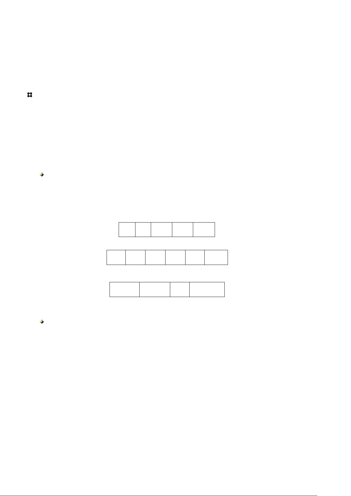
DA
SA
Type
Data
CRC
DA
SA
Tag
Type
Data
CRC
0X8100
Priority
CFI
VLAN ID
network, and communication connection between devices as are in the same physical partitions. Through the
virtual local area network (LAN), can divide the network into multiple partitions, but do not need to change the
physical connection between the devices
SW-GE1008F switches support Tag 802.1 Q VLAN mode
802.1Q Tag VLAN
Based on the Tag of 802.1 Q VLAN with VID to divide different VLAN, when the data frame through the
switch, switch according to the Tag header VID information of frame to identify their VLAN (but if frame
without the Tag header, then the application frame through the port by default VID information to identify their
VLAN), which makes all belong to the data frame of the VLAN, whether single site frame, multiple frames or
broadcast frame, will be limited in the logical VLAN. This will make the group able to communicate with each
other, each other between the host and not affected by other hosts, just as they exist in separate VLANs
In the initial, VLAN switches, mutual recognition of each vendor can't compatible.IEEE802.1Q virtual
local area network (LAN) - the new standard after the founding, the equipment of different
manufacturers can use in a network at the same time, the switch which support IEEE802.1Q can
communicate with other switches.IEEE802.1Q defines a new frame format, it's behind the standard
Ethernet frame source address joined a tag header.
Picture 4-1 802.1Q tag header
Set the Tag VLAN, there are five configuration to consider:
1) VLAN ID
1-4094。Set the VLAN identifier, to identify a particular VLAN, SW-GE1008F lets you set
the VLAN ID of the range of 1-4094
2) VLAN Aware
Used to determine the input packets if put on the Tag, is based on the VLAN ID Tag come
forward or on PVID
3)The output of the port rules(Tag/Untag)
Identify whether or not to bring the output of the frame from the port tag. The Tag says the
port forwarding the frame with the Tag header, even if the frame without the Tag when received;
Untag show the port from the frame without the tag, even if the frame with the tag when received
4)The default port PVID
When the switch is not obtain a frame of the tag to belong to which VLAN (Untagged
frames), then the default VID of receiving port to determine the frame in which VLAN for
forwarding. The default VID port Settings in the range of 1-4094

13
5)Port input filtering
When open port input filtering, the port will check the VID of received frame, if the port is
not belong to this identified VID and VLAN discards the frame. When receiving the frame
without the tag, to filter according to the receiving port's default VID
6)The types of port receives packets
The switch can set the port to receive the packet type, divide into all types of data packets,
including tagged and untagged Or receive only tagged packets
Manage VLAN
A series of switches support management VLAN Settings, only via the members of the VLAN port can
manage the switch based on the management of the Web and the SNMP management, etc. If also opened the
switch’s DHCP function, then the DHCP server can assign IP or other information to the exchange only by a
member of the management VLAN ports
4.4 Trunk
Trunk provides a port polymerization mechanism, it can connect several low-speed together, forming
a high-speed connection. For example, the four 1000 Mbps full-duplex Ethernet port to form the total
bandwidth at 8000 Mbps connection together by Trunk technology , these ports can be view as a port
After setting Trunk, the switch from the outside and the Trunk and Trunk ports in a VLAN other port
load automatically assigned to the various ports in the Trunk.SW-GE1008F Trunk load balancing
allocation is based on the source address of the frame and the destination address, can make the load
for uniform distribution in each port of Trunk.
When one member of the Trunk link disconnect, switches automatically distribute the data on the link of
Trunk, the other link when disconnect the link will restore to the original load distribution.
Set up rules of Trunk:
1) SW-GE1008F support the Trunk quantity is 8, port quantity for 2 ~ 10 in each group
================================================================
What should pay attention to set up a truck:
1)At the time of setting Trunk, either create Trunk or adding a port to the Trunk, to join the members
of a Trunk port will be deleted from all of the VLAN. If remove members from the Trunk port or
delete the whole Trunk, the original members of the Trunk port will return to its original VLAN.
2)The effect between the Trunk and MAC address binding, port mirror
================================================================
4.5. Port Mirror
Copy a send/receive frames to a port , forwarded to the specified port (mirror), so that network management
personnel can analyze and evaluate mirror image data frame of the port
===================================================================

14
Note: in SW-GE1008F, at the same time can be only one port is set to mirror port, mirrored there can be
multiple, and mirror ports and the mirrored should be in the same VLAN.
4.6 Broadcast storm control
Broadcast storm refers to broadcast frame on the network by the number has increased
dramatically and affects normal network communication of the abnormal phenomenon.
Broadcast control allows the port to appear on the network broadcast frame reaches a certain
amount of control, in order to prevent the broadcast storm.SW-GE1008F port supports various
types of broadcast packets forwarding rate, broadcast packet forwarding speed rate, rate of DLF
packet forwarding .Also supports including ICMP packet forwarding rate at the same time, the
study frame of the forward rate, multicast packets forwarding rate, prevent malicious attacks in
the network, also can turn off these control. The control range of various data confirmed to 1
Kbps, 2 Kbps, 4 Kbps, 8 Kbps, 16 Kbps, 32 Kbps, 64 Kbps and 128 Kbps and 256 Kbps
4.7 QoS
SW-GE1008F provides frame transmission mechanism for different priority (priority), according to the
transmission level table switches will receive priority mapped to the frame transmission level, high level of
frame will be priority. Classification can be set based on the priority of port priority and DSCP priority, 802.1 p.
The user can select the current priority classification criteria.SW-GE1008F support four priority queue.
Based on the port priority
If the current QoS options based on port priority, each port of switch can set the priority queue, support four
priority queue, for receives frames of port, whether the frame with priority information, switches will be
based on the port priority queue for processing.
Base on 802.1P priority
Under the Port VLAN mode, for Port receives the frame, whether the frame with priority information,
switches will be based on the default Port priority for processing. In the Tag VLAN mode, if the port
receives the frame without head Tag, the default priority is based on port for processing; If the head
port receives the frame with the tag, switches will be based on the frame of the tag header contains the
priority corresponding priority queue for processing.> a priority queue
DSCP priority
DSCP (Difference Service of Class Priority) Service type is an 8 bit of IP TOS field in the first 6 bit.
Using to represent a priority, without this series switches provide basis on DSCP priority queue the
division of functions.6 bit DSCP is 0 ~ 64, can be mapped to different four priority queue.
4.8 Switch file update
 Loading...