

Page 1
8
027908 367358
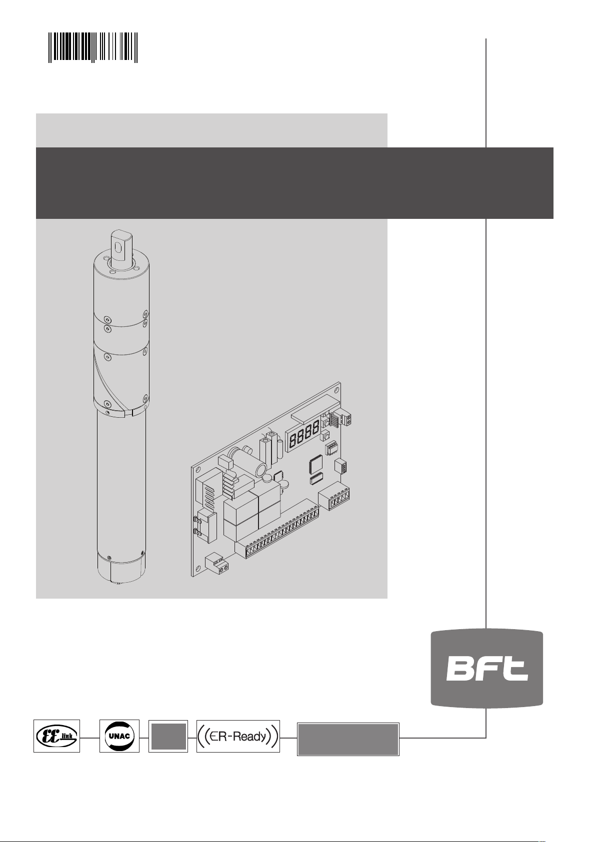
QUADRO COMANDO
CONTROL PANEL
CENTRALE DE COMMANDE
SELBSTÜBERWACHENDE STEUERUNG
CUADRO DE MANDOS
BEDIENINGSPANEEL
D811703 00100_04 02-12-11
MONTAGEANLEITUNG
ISTRUZIONI DI INSTALLAZIONE
INSTALLATION MANUAL
INSTRUCTIONS D’INSTALLATION
HIDE SW
HIDE SW
INSTRUCCIONES DE INSTALACION
INSTALLATIEVOORSCHRIFTEN
CB-HIDE
CB- HIDE
Attenzione! Leggere attentamente le “Avvertenze” all’interno! Caution! Read “Warnings” inside carefully! Attention! Veuillez lire attentivement les Avertissements qui se trouvent à l’intérieur! Achtung! Bitte lesen Sie
aufmerksam die „Hinweise“ im Inneren! ¡Atención¡ Leer atentamente las “Advertencias”en el interior! Let op! Lees de “Waarschuwingen”tigre aan de binnenkant zorgvuldig!
Page 2

INSTALLAZIONE VELOCE-QUICK INSTALLATION-INSTALLATION RAPIDE
SCHNELLINSTALLATION-INSTALACIÓN RÁPIDA - SNELLE INSTALLATIE
PREDISPOSIZIONE TUBI, TUBE ARRANGEMENT,
2
2x0,75 mm
PRÉDISPOSITION DES TUYAUX, VORBEREITUNG DER LEITUNGEN,
DISPOSICIÓN DE TUBOS, VOORBEREIDING LEIDINGEN.
2
6x1,5 mm
2
5x0,75 mm
2
5x0,75 mm
3x0,75 mm
RG58
2x1,5 mm
6x1,5 mm
2x0,75 mm
2
2
2
2
A
3x1,5 mm
Ø16
2
B
1
110°
max
2
110° max
Ø12
2 - HIDE SW
Page 3
ITALIANO ENGLISH
D811703 00100_04
50
Ø 80
35
F
JP3
620
544
Collegamento di 1 coppia di fotocellule non vericate // Connection of 1 pair of
non-tested photocells // Connexion 1 paire photocellules no vériées // Anschluss
von einem Paar nicht überprüften Fotozellen // Conexión de 1 par fotocélulas no
comprobadas // A ansluiting van 1 paar fotocellen anders dan “trusted device”.
181211 15
COM
24V ~
Tx 1
5
4
3
2
2
1
1
Rx 1
PHOT
LOGICA test fotocellule OFF,
Photocell test LOGIC OFF,
LOGIQUE essai photocellules Désactivée,
LOGIK Test Fotozellen OFF,
LÓGICA prueba fotocélulas OFF,
LOGICA test fotocellen OFF.
Ø10
ANT.
M8
Ø20
C
E
Ø50
Ø30
236
194
100
D
FRANÇAIS ESPAÑOL
1
SCA II
JP9
(*)
22
33
24V
44
11 12 21
24 V~
Connettore programmatore palmare,
Palmtop programmer connector,
Connecteur programmateur de poche,
Steckverbinder Palmtop-Programmierer,
Conector del programador de bolsillo,
Connector programmeerbare palmtop.
Display + tasti programmazione,
Display plus programming keys,
Acheur et touches de programmation,
Display und Programmierungstasten,
Pantalla mas botones de programacion,
Display meerdere toetsen programmeur.
230V
°
CH
JP9
1920 21 22
(*) 110V
24V
Altre tensioni disponibili a richiesta
*
Other voltages available on request
Autres tensions disponibles sur demande
Weitere Spannungen auf Anfrage erhältlich
Otras tensiones disponibles a petición
Andere spanningen op aanvraag beschikbaar
JP21
ANT
SHIELD
29 30
FAULT-BAR
BAR
27
CLOSE
S2
S1
S3
24 25 26 28
20 21 22
OPEN
COM FC
PED
FAULT
PHOT
STOP
START
NO
NC
NO
NO
NO
NO
NC
NC
NO
DEUTSCH
COM
VSafe VSafe +
24V ~(-)
24V ~(+)
F2 1AT
F1 1,25 AT (230V)
F1 2,5 AT (110V)
230V ~
25W max.
FC M2
+
FC M1
+
*
N
L
1 2 3 4 5 6 7 8 9 10 1112 131415 16 1718 19
230V ~
*
4
6
5
3
1
M2
2
5
6
3
2
1
4
NEDERLANDS
M1
HIDE SW - 3
Page 4
G
MEMORIZZAZIONE RADIOCOMANDO
MEMORIZING REMOTE CONTROLS
MÉMORISATION RADIOCOMMANDE
ABSPEICHERUNG DER FERNBEDIENUNG
MEMORIZACION DEL RADIOMANDO
MEMORISEREN AFSTANDSBEDIENINGD
+
8888
OK
REGOLAZIONE FINECORSA,
ADJUSTING THE LIMIT SWITCHES,
REGLAGE DE LA FIN DE COURSE,
EINSTELLUNG DER ENDSCHALTER,
REGULACION DE LOS FINALES DE CARRERA,
REGELING EINDAANSLAGEN.
+
8888
OK
+
OK
PArA
x 2
x 2
H
REGOLAZIONE AUTOSET,
ADJUSTING AUTOSET,
REGLAGE AUTOSET,
EINSTELLUNG AUTOSET,
REGULACION AUTOSET,
REGELING AUTOSET.
+
8888
OK
I
OK
x 2
PArA
x 2
RADIO
OK
Agg.start - Adjouter
start - zufuegstart anad start
OK
tasto nascosto-hidden
button-
touche
cachee-verst.taste
rilascia-releaserelache -
-loslassen-suelte
x 6
REG FC
OK
APERTURA / OPENING / OUVERTURE
ÖFFNUNG / APERTURA / OPENING:
op 2
OK
+
1 2
OK
op 1
prg
+
21
OK
CHIUSURA / CLOSING / FERMETURE
SCHLIESSUNG / CIERRE / SLUITING:
cl 1
prg
OK
PArA
OK
. . .3 . . .2 . . .1
AUTO OPEN
+
x 2
x 5
autoset
. . . . . . . .
Fine
- End - Fin
4 - HIDE SW
tasto desideratodesider button touche
gevue
desireetaste-tecla deseada
ok 01
+
x 3
ok
OK
OK
cl 2
21
prg
21
prg
-
-
Ersu
. . .3 . . .2 . . .1
AUTO CLOSE
ko
ok
Page 5
FOTOCELLULE
FOTOZELLEN
Morsettiera,
D811703 00100_04
Terminal board,
Bornier,
Kemmleiste
Tablero de bornes,
Aansluitkast,
TEST PHOT=OFF
1
2
3
PHOTOCELLS
FOTOCÉLULAS
11
12
1-PHOT
13
14
1-PHOT
13
14
2-PHOT
13
14
VSafe -
VSafe +
24V~ (-)
24V~ (+)
1
TX1 RX1
2
1
TX1 RX1
2
1
TX1 RX1
2
1
TX2 RX2
2
PHOTOCELLULES
FOTOCELLEN
1
11
2
12
3
15
4
5
18
1
11
2
12
3
15
4
19
5
18
11
1
12
2
3
15
4
18
5
11
1
12
2
3
19
4
15
5
COSTE
LEISTEN
24 25 26 27 28
BAR
11
27
15
12
11
13
27
28
15
12
11
13
27
15
12
11
13
15
28
12
11
SAFETY EDGES
CANTOS
FAULT-BAR
6
5
4
3
2
Bar 1
1
6
5
4
3
2
1
6
5
4
3
2
1
6
5
4
3
2
1
Bar 1
Bar 1
Bar 2
1-BAR
1-BAR
2-BAR
LINTEAUX
RANDEN
A
C
J
TEST BAR = OFF
B
4
TEST PHOT = ON
5
3-PHOT
4-PHOT
13
1
TX1 RX1
2
14
13
1
TX2 RX2
2
14
13
1
TX3 RX3
2
14
13
1
TX1
2
14
13
1
TX2
2
14
13
1
TX3
2
14
13
1
TX4
2
14
RX1
RX2
RX3
RX4
1
2
3
4
5
1
2
3
4
5
1
2
3
4
5
1
2
3
4
5
1
2
3
4
5
1
2
3
4
5
1
2
3
4
5
11
12
15
18
11
12
2-SCS1-MA
1-SCS1-MA
11
12
3-SCS1-MA
19
15
11
12
15
18
11
12
2-SCS1-MA
1-SCS1-MA
11
12
3-SCS1-MA
5-SCS1-MA
4-SCS1-MA
11
12
6-SCS1-MA
19
15
4-SCS1-MA
5-SCS1-MA
1-SCS1-MA
2-SCS1-MA
13
6
27
5
15
4
3
12
2
11
13
1
6
Bar 1
5
4
3
12
2
11
13
27
15
12
11
13
1
6
5
4
3
2
1
6
Bar 2
Bar 1
5
4
3
12
2
11
1
Bar 2
3-BAR
6-SCS1-MA
4-BAR
4-SCS1-MA
5-SCS1-MA
3-SCS1-MA
6-SCS1-MA
D
13
6
15
5
28
4
3
12
2
11
13
12
11
13
15
28
12
11
Bar 3
1
6
5
4
3
E
2
Bar 3
1
6
5
4
3
2
Bar 4
1
TEST BAR = ON
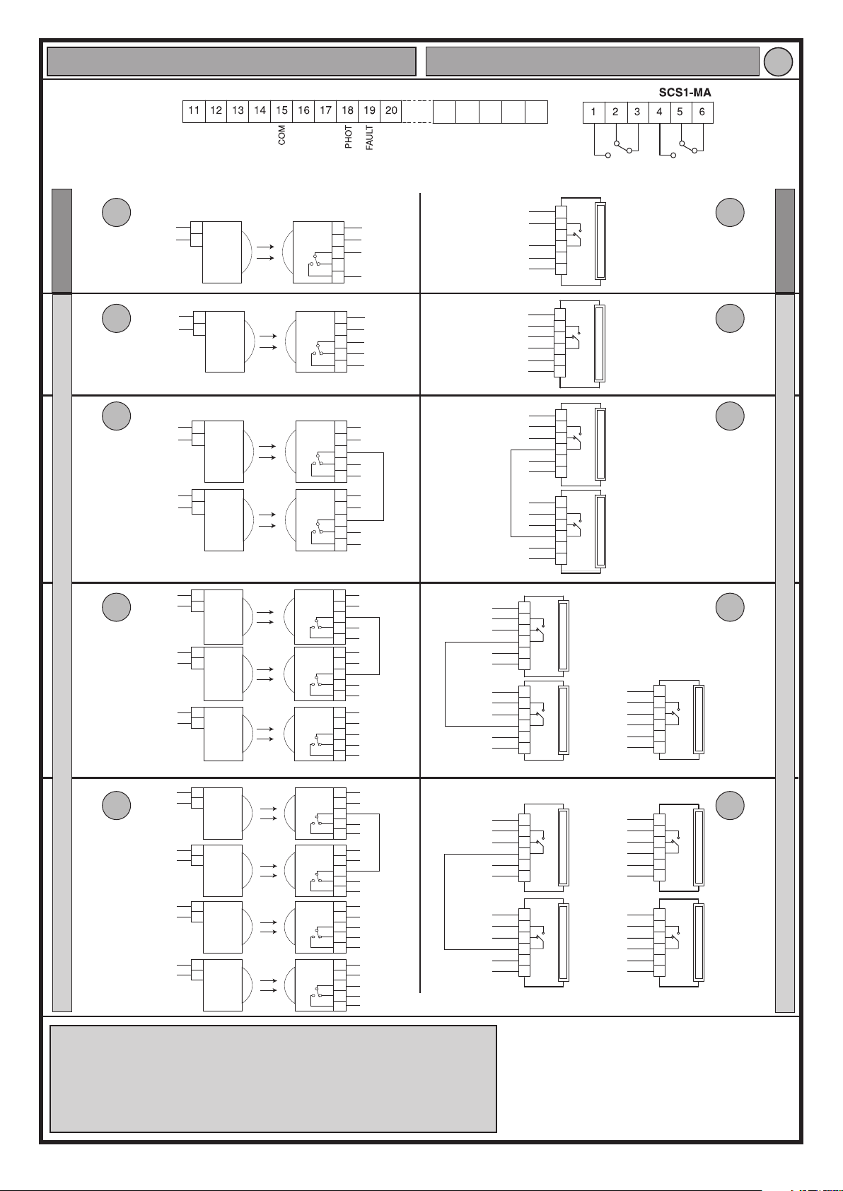
Numero massimo di dispositivi vericati: 6 (ma non più di 4 per tipo),
Maximum number of tested devices: 6 (but no more than 4 per type),
Nombre maximum dispositif vériés: 6 (mais pas plus de 4 par type),
Max. Anzahl der überprüften Geräte: 6 (jedoch nicht mehr als 4 je Typ),
Número máximo dispositivos comprobados: 6 (pero no más de 4 por tipo),
Maximumaantal “trusted devices”: 6 (maar niet meer dan 4 per type).
HIDE SW - 5
Page 6
2 s
UNIDA
K
L
Programmeerbare Universele Palmtop
SCHEDA DI ESPANSIONE
EXPANSION BOARD
CARTE D’EXPANSION
ERWEITERUNGSKARTE
TARJETA DE EXPANSIÓN
UITBREIDINGSKAART
Inversione del moto / Reversing motion / Inversion du mouvement
Umkehrung der Bewegung / Inversión del movimiento / Omkering van de beweging.:
0
M1
Inversione del moto / Reversing motion / Inversion du mouvement
Umkehrung der Bewegung / Inversión del movimiento / Omkering van de beweging.:
M2
M2 M1
1
M
6 - HIDE SW
M2
M1
M1 M2
Page 7

Press the OK key
Control unit software version
N. total manoeuvres (x 100)
N. radio control devices memorised
ACCESS TO MENUS Fig. 1
Scroll up
Scroll down
Confirm/Switch on display
Exit Menù
end
end
end
radio
param. 1
param. 2
param. . . .
logic. 1logic
logic. 2
logic. . . .
add. start
Add. 2ch
read
erase 64
COD RX
hidden button
hidden button
PRG.
1A9C
+/-
OK
22FD
See PARAMETERS MENU
See LOGIC MENU
release ok 01
release
01 t1
OK
desired button
desired button
See RADIO MENU
0 1
OK
ok 01
end
end
end
end
language
default
autoset
l.sw adj
v
ITA
-
FRA
-
DEU
-
ENG
-
esp
PRG
OK
+
OK
+
OK
+
OK
+
OK
LIMIT SWITCH ADJUSTMENT
DIAGNOSTICS
CODE
Er01
Er02
Er1X *
Er2X *
Er3X *
Er4X *
Er5X *
Er61
DESCRIPTION NOTES
photocell test anomaly
safety edge test anomaly
hardware anomaly check connections to motor
encoder anomaly
amperostop anomaly make sure movement is not hindered
thermal cutout anomaly allow automated device to cool
communication anomaly
buer battery power
anomaly
* X = 0,1,…,9,A,B,C,D,E,F
DIAGNOSTICS and WARNINGS
check photocell connection and/or parameter/logic settings
check safety edge connection and/or parameter/logic settings
motor is moved manually and/or check
encoder and relevant wiring
check connection with accessory devices
and/or expansion boards or serial-connected devices
automated device running on battery
power
12 - HIDE SW
Page 8

INSTALLER WARNINGS
WARNING! Important safety instructions. Carefully read and comply with
all the warnings and instructions that come with the product as incorrect
installation can cause injury to people and animals and damage to proper-
D811703 00100_04
ty. The warnings and instructions give important information regarding
safety, installation, use and maintenance. Keep hold of instructions so that
you can attach them to the technical le and keep them handy for future
reference.
GENERAL SAFETY
This product has been designed and built solely for the purpose indicated herein.
Uses other than those indicated herein might cause damage to the product and
create a hazard.
- The units mak ing up the machine and its installation must meet the requirements
of the following European Directives, where applicable: 2004/108/EC, 2006/95/
EC, 2006/42/EC, 89/106/EC, 99/05/EC and later amendments. For all countries
outside the EEC, it is advisable to comply with the standards mentioned, in
addition to any national standards in force, to achieve a good level of safety.
- The Manufac turer of this product (hereinafter referred to as the “Firm”) disclaims
all responsibility resulting from improper use or any use other than that for
which the product has been designed, as indicated herein, as well as for failure
to apply Good Practice in the construction of entry systems (doors, gates, etc.)
and for deformation that could occur during use.
- Installation must be carried out by qualied personnel (professional installer,
according to EN 12635), in compliance with Good Practice and current code.
- Before commencing installation, check the product for damage.
- Before installing the product, make all structural changes required to produce
safety gaps and to provide protection from or isolate all crushing, shearing and
dragging hazard areas and danger zones in general. Check that the existing
structure meets the necessary strength and stability requirements.
- The Firm is not responsible for failure to apply Good Practice in the construction
and maintenance of the doors, gates, etc. to be motorized, or for deformation
that might occur during use.
- Make sure the stated temperature range is compatible with the site in which the
automated system is due to be installed.
- Do not install this product in an explosive atmosphere: the presence of ammable
fumes or gas constitutes a serious safety hazard.
- Disconnect the electricity supply before performing any work on the system.
Also disconnect buer batteries, if any are connected.
- Before connecting the power supply, make sure the product’s ratings match the
mains ratings and that a suitable residual current circuit breaker and overcurrent
protection device have been installed upline from the electrical system. Have
the automated system’s mains power supply tted with a switch or omnipolar
thermal-magnetic circuit breaker with a contact separation that meets code
requirements.
- Make sure that upline from the mains power supply there is a residual current
circuit breaker that trips at no more than 0.03A as well as any other equipment
required by code.
- Make sure the ear th system has been installed correctly: earth all the metal parts
belonging to the entry system (doors, gates, etc.) and all parts of the system
featuring an earth terminal.
- Installation must be carried out using safety devices and controls that meet
standards EN 12978 and EN 12453.
- Impact forces can be reduced by using deformable edges.
- I n the event impact forces exceed the values laid down by the relevant standards,
apply electro-sensitive or pressure-sensitive devices.
- Apply all safety devices (photocells, safety edges, etc.) required to keep the
area free of impact, crushing, dragging and shearing hazards. Bear in mind the
standards and directives in force, Good Practice criteria, intended use, the installation environment, the operating logic of the system and forces generated
by the automated system.
- Apply all signs required by current code to identify hazardous areas (residual
risks). All installations must be visibly identied in compliance with the provisions
of standard EN 13241-1.
- This product cannot be installed on leaves incorporating doors (unless the motor
can be activated only when the door is closed).
- I f the automated system is installed at a height of less than 2.5 m or is accessible,
the electrical and mechanical parts must be suitably protected.
- Install any xed controls in a position where they will not cause a hazard, away
from moving parts. More specically, hold-to-run controls must be positioned
within direct sight of the part being controlled and, unless they are key operated,
must be installed at a height of at least 1.5 m and in a place where they cannot
be reached by the public.
- Apply at least one warning light (ashing light) in a visible position, and also
attach a Warning sign to the structure.
- Attach a label near the operating device, in a permanent fashion, with information
on how to operate the automated system’s manual release.
- Make sure that, during operation, mechanical risks are avoided or relevant protective measures taken and, more specically, that nothing can be banged, crushed,
caught or cut between the part being operated and surrounding parts.
- Once installation is complete, make sure the motor automation settings are
correct and that the safety and release systems are working properly.
- Only use original spare parts for any maintenance or repair work. The Firm disclaims all responsibility for the correct operation and safety of the automated
system if parts from other manufacturers are used.
- Do not make any modications to the automated system’s components unless
explicitly authorized by the Firm.
- Instruct the system’s user on what residual risks may be encountered, on the
control systems that have been applied and on how to open the system manually
in an emergency. give the user guide to the end user.
- Dispose of packaging materials (plastic, cardboard, polystyrene, etc.) in accordance with the provisions of the laws in force. Keep nylon bags and polystyrene
out of reach of children.
WIRING
WARNING! For connection to the mains power supply, use: a multicore cable
with a cross-sectional area of at least 5x1.5mm
with three-phase power supplies or 3x1.5mm2 for single-phase supplies (by
way of example, type H05 VV-F cable can be used with a cross-sectional area
of 4x1.5mm2). To connect auxiliary equipment, use wires with a cross-sectional
area of at least 0.5 mm2.
- Only use pushbuttons with a capacity of 10A-250V or more.
- Wires must be secured with additional fastening near the terminals (for example,
using cable clamps) in order to keep live parts well separated from safety extra
low voltage parts.
- During installation, the power cable must be stripped to allow the earth wire
to be connected to the relevant terminal, while leaving the live wires as short
as possible. The earth wire must be the last to be pulled taut in the event the
cable’s fastening device comes loose.
WARNING! safety extra low voltage wires must be kept physically separate from
low voltage wires.
Only qualied personnel (professional installer) should be allowed to access
live parts.
CHECKING THE AUTOMATED SYSTEM AND MAINTENANCE
Before the automated system is nally put into operation, and during maintenance
work, perform the following checks meticulously:
- Make sure all components are fastened securely.
- Check starting and stopping operations in the case of manual control.
- Check the logic for normal or personalized operation.
- For sliding gates only: check that the rack and pinion mesh correctly with 2 mm
of play; keep the track the gate slides on clean and free of debris at all times.
- Check that all safety devices (photocells, safety edges, etc.) are working properly
and that the anti-crush safety device is set correctly, making sure that the force
of impact measured at the points provided for by standard EN 12445 is lower
than the value laid down by standard EN 12453.
- Make sure that the emergency operation works, where this feature is provi-
ded.
- Check opening and closing operations with the control devices applied.
- Check that electrical connections and cabling are intact, making extra sure that
insulating sheaths and cable glands are undamaged.
- While performing maintenance, clean the photocells’ optics.
- When the automated system is out of service for any length of time, activate the
emergency release (see “EMERGENCY OPERATION” section) so that the operated
part is made idle, thus allowing the gate to be opened and closed manually.
- If the power cord is damaged, it must be replaced by the manufacturer or their
technical assistance department or other such qualied person to avoid any
risk
SCRAPPING
Materials must be disposed of in accordance with the regulations in force. There
are no particular hazards or risks involved in scrapping the automated system. For
the purpose of recycling, it is best to separate dismantled parts into like materials
(electrical parts - copper - aluminium - plastic - etc.).
DISMANTLING
If the automated system is being dismantled in order to be reassembled at another
site, you are required to:
- Cut o the power and disconnect the whole electrical system.
- Remove the actuator from the base it is mounted on.
- Remove all the installation’s components.
- See to the replacement of any components that cannot be removed or happen
to be damaged.
2
or 4x1.5mm2 when dealing
Anything that is not explicitly provided for in the installation manual is not allowed. The operator’s proper operation can only be
guaranteed if the information given is complied with. The Firm shall
not be answerable for damage caused by failure to comply with the
instructions featured herein.
While we will not alter the product’s essential features, the Firm reserves the right, at any time, to make those changes deemed opportune to improve the product from a technical, design or commercial
point of view, and will not be required to update this publication
accordingly.
ENGLISH
AVVERTENZE PER L’INSTALLATORE D811766_04
HIDE SW - 13
Page 9

INSTALLATION MANUAL
2) GENERAL OUTLINE
The HIDE SW control panel is supplied by the manufacturer with standard setting.
Any alteration must be set by means of the incorporated display programmer or by
means of universal palmtop programmer. The Control unit completely supports the
EELINK protocol.
Its main characteristics are:
- Control of two HIDE SW motors
- Electronic torque control with obstacle detection
- Encoder control inputs
- Separate inputs for safety devices
- Incorporated rolling-code radio receiver with transmitter cloning
The board is provided with a terminal board which can be pulled out for easier maintenance or replacement. The board is supplied with a series of pre-wired jumpers to
facilitate the installer’s work.
The jumpers relate to the following terminals: 15-17,15-18, 15-27. If the abovementioned terminals are in use, remove their respective jumpers.
WARNING: the motor comes in the CLOSED position.
DO NOT ALTER THE POSITION OF THE MOTOR UNTIL INSTALLATION HAS BEEN
COMPLETED.
Install the motor with the leaf closed, then remove the seal.
CHECK
The HIDE SW panel carries out a control (check) on the starting relays and safety devices
(photocells) before carrying out each opening and closing cycle.
In case of malfunction, check the devices connected for regular operation and check
the wiring.
3) TECHNICAL DATA
MOTOR
Power supply 230V~ ±10% 50Hz*
Mains/low voltage insulation > 2MOhm 500V
Power input 40W
Max. torque 345Nm
Speed 7.5°/s
Protection rating IP 45
Max. leaf length 2m
Max. leaf weight 150 Kg
Leaf surface area 3 sq m / 5 sq m
Operator weight 8kg (≈80N)
Use residential
Max. opening angle 110°
Working temperature -20 / +60°C
Wind resistance class 2 / class 1
CONTROL UNIT
Thermal protection Software
Dielectric strength mains/low voltage 3750V~ per 1 minute
Motor output current 7.5A+7.5A max
Motor relay commutation current 10A
Maximum motor power 200W + 200W (24V
Supply to accessories
Gate-open warning light Contatto N.O. (24V~/1A max)
Blinker 24V~ 25W max
Dimensions see Fig. C
Fuses see Fig. E
N° of combinations
Max. n° of remotes that
can be memorized
(* other voltages available on request)
WARNING:
- the actuator has been designed to be integrated into the gate’s structure.
- do not make holes in the structure anywhere around the space housing
the actuator as this could compromise the machine’s characteristics.
Usable transmitter versions:
All ROLLING CODE transmitters compatible with
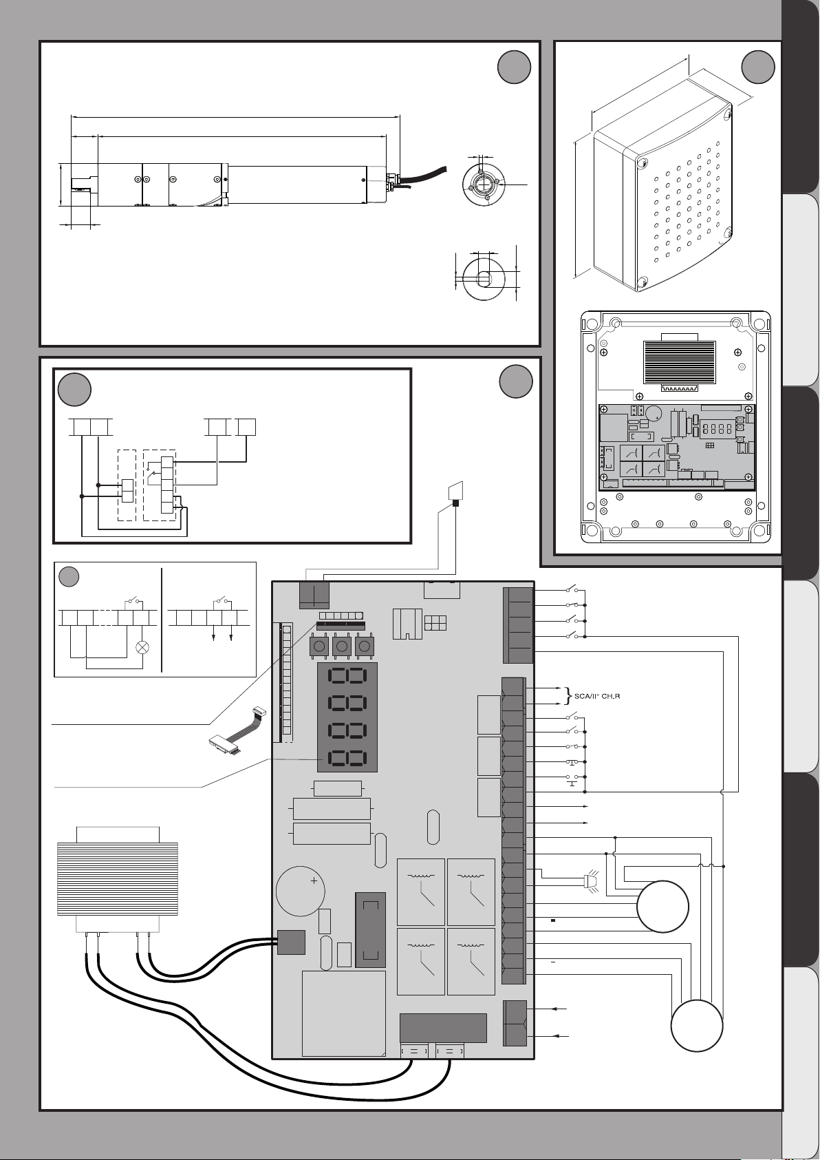
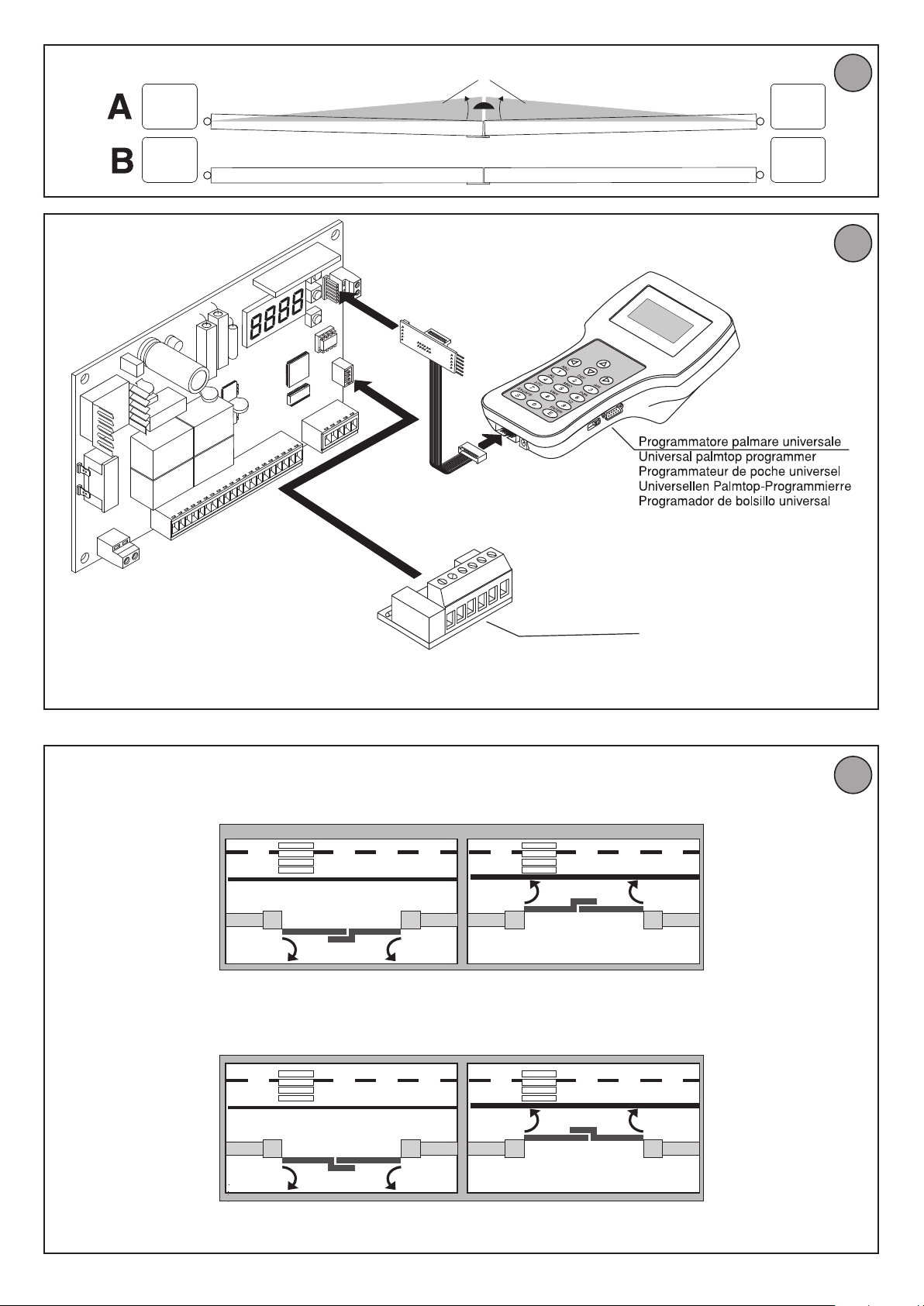
4) TUBE ARRANGEMENT Fig. A
5) ASSEMBLING THE MOTOR FIG.B
AWARNING:
- line the seal up with the leaf in the closed position (Fig.B Ref. 1)
- Remove the seal (Fig.B Ref. 2)
- Power the motor only once it has been coupled with the leaf and hinges.
24V~ (180mA max absorption)
24V~safe (180mA max absorption)
4 billion
63
)
6 CONNECTION OF 1 PAIR OF PHOTOCELLS AND 1 PAIR OF SAFETY EDGES,
UNTESTED Fig. F
7) TERMINAL BOARD CONNECTIONS Fig. E
WARNING – During the wiring and installation operations, refer to the current
standards as well as principles of good technical practice.
Wires powered at dierent voltages must be physically separated, or suitably
insulated with at least 1 mm extra insulation. The wires must be clamped by an
extra fastener near the terminals, for example by bands.
All the connection cables must be kept at an adequate distance from the dissipator.
TERMINAL DESCRIPTION
L-N
3-4-5
6-7-8
9-10
11-12
13-14
15-16 START pushbutton (N.O.).
15-17
15-18
19
15-20
21-22
23 Not used
24 Limit switch common (Motors 1 and 2 cable 4
15-25 OPEN button (N.O.).
15-26 CLOSE button (N.O.)
15-27 EDGE INPUT (N.C.) If not used, leave the bridge 15-27 connected.
28 EDGE FAULT (N.O.)
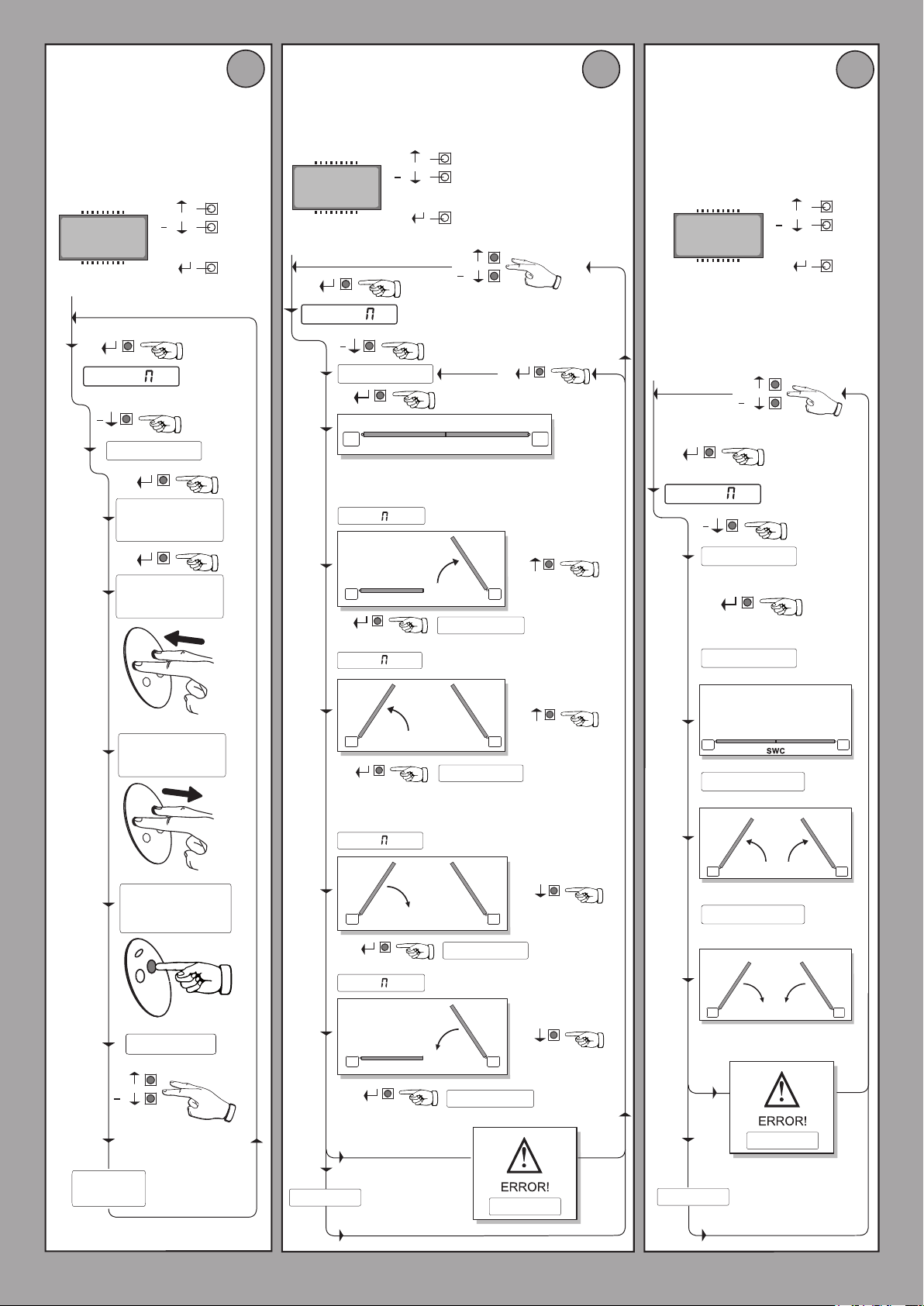
8 MEMORIZING REMOTE CONTROLS Fig. G
9) LIMIT SWITCH SETTING MENU Fig. H
If the leaf moves in the wrong direction, adjust the “motor reverse” logic accordingly (+ opening / - closing).
NOTE: these manoeuvres are carried out in hold-to-run mode at reduced speed
and without safety device activation. If the “1 ot on” logic is set, only the
messages relating to motor 2 will be displayed (“OP 2” e “ CL 2”).
10) AUTOSET MENU Fig. I
Allows you to automatically set the Motor torque.
WARNING!! The autosetting operation is only to be carried out after checking the
exact leaf movement (opening/closing) and correct limit switch activation.
You are advised to carry out an autosetting procedure each time you modify the
slow-down speed or space.
WARNING! During the autoset phase, the obstacle detection function is not
active, therefore the installer must control the automation movement and prevent persons and things from approaching or standing within the automation
working range.
In the case where buer batteries are used, autosetting must be carried out with
the control panel supplied by mains power voltage.
WARNING: The torque values xed by means of the autoset procedure
refer to the slow-down speed xed during the same procedure. If the
slow-down speed or space is modied, a new autosetting manoeuvre must
be carried out.
WARNING: Check that the impact force value measured at the
points established by the EN 12445 standard is lower than that specied in the EN 12453 standard.
Incorrect sensitivity setting can cause injuries to persons or
animals, or damage to things.
Single-phase mains power supply 230V
Connection to motor 1:
3 motor 1 cable 1
4 motor 1 cable 2
5 motor 1 cable 3
Connection to motor 2:
6 motor 2 cable 2
7 motor 2 cable 1
8 motor 2 cable 3
Connection to blinker (24V
Output 24V~ 180mA max - supply to photocells or other devices.
11 motore 1-2 cable 5
12 motore 1-2 cable 6
Output 24V
with checking function (Fig. J).
STOP pushbutton (N.C.). If not used, leave the bridge 15-17
connected.
PHOTOCELL input (N.C.). If not used, leave the bridge 15-18
connected.
FAU LT input (N.O.). Input for photocells provided with checking
N.O. contact (Fig. J).
PEDESTRIAN pushbutton input (N.O.). Activation is carried out
by motor 2; if the opening cycle has started (not from pedestrian
function), the pedestrian command has no eect.
Output for gate-open warning light output (N.O. contact (24V
max)) or alternatively 2nd radio channel (Fig. E rif. 1).
~ V safe 180mA max - supply to photocell transmitters
~ 25W max)
~ ±10%
~/1A
)
14 - HIDE SW
Page 10

INSTALLATION MANUAL
11) SAFETY DEVICES
Note: only use receiving safety devices with free changeover contact.
11.1) TESTED DEVICES Fig. J
D811703 00100_04
12) CLOSING LIMIT SWITCH PRESSURE Fig. K
13) CONNECTION WITH EXPANSION BOARDS AND UNIVERSAL HANDHELD
PROGRAMMER Fig. L
Refer to specic manual.
ACCES TO MENU: Fig. 1
PARAMETERS MENU para
(TABLE “A” PARAMETERS)
LOGIC MENU logic
(TABLE “B” LOGIC)
RADIO MENU RADIO
Logic Description
add start
add 2ch
read
erase 64
cod RX
v
- IMPORTANT NOTE: THE FIRST TRANSMITTER MEMORIZED MUST BE
IDENTIFIED BY ATTACHING THE KEY LABEL (MASTER).
Add Start Key
associates the desired key with the Start command
Add 2ch Key
associates the desired key with the 2nd radio channel command
Read
Checks a key of a receiver and, if memorized, returns the
number of the receiver in the memory location (from 01 to
63) and number of the key (T1-T2-T3 or T4).
Erase List
WARNING! Erases all memorized remote controls from
the receiver’s memory.
Read receiver code
Displays receiver code required for cloning remote controls.
ON = Enables remote programming of cards via a previously
memorized W LINK transmitter. It remains enabled for
3 minutes from the time the W LINK remote control is
last pressed.
OFF=W LINK programming disabled.
In the event of manual programming, the rst transmitter assigns the RECEIVER’S
KEY CODE: this code is required to subsequently clone the radio transmitters.
The Clonix built-in on-board receiver also has a number of important advanced
features:
• Cloningofmastertransmitter(rollingcodeorxedcode)
• Cloningtoreplacetransmittersalreadyenteredinreceiver
• Transmitterdatabasemanagement
• Receivercommunitymanagement
To use these advanced features, refer to the universal handheld programmer’s
instructions and to the CLONIX Programming Guide, which come with the universal handheld programmer device.
LANGUAGE MENU language
Used to set the programmer’s language on the display.
DEFAULT MENU default
Restores the controller’s default factory settings.
AUTOSET MENU Autoset
See Fig. I and “Autoset Men”.
LIMIT SWITCH SETTING MENU (reg FC)
See Fig. H and “
MONITORING
The torque parameter denes the maximum acceptable dierence between the
instant torque and the expected instant torque , i.e. it indicates sensitivity to the
obstruction. The lesser the torque parameter, the greater the sensitivity to the
obstruction (Torque 1= maximum sensitivity).
14 ADJUSTING PROCEDURE
Before switching on, check electrical connections.
- Set the following parameters: Automatic Closing Time, Opening and closing
delay times, speed and Slow-down Distance.
- Set all the logics.
- Carry out the autoset procedure.
After completing the autoset procedure, the Motor fast time and the Torque can
be manually adjusted.
WARNING! Any incorrect setting can cause injuries to persons and animals
or damage to things.
WARNING:check that the impact force value measured at
the points established by the EN 12445 standard is lower than that
specied in the EN 12453 standard.
To obtain a better result, it is advisable to carry out the autoset procedure and
the fast time setting with the motors at rest (i.e. not overheated by a considerable
number of consecutive manoeuvres).
Limit Switch Setting menu”
ENGLISH
TABLE “A” PARAMETERS MENU - PARA
Logic min. max. Default
tca
open delay
ti
e
cls delay
ti
e
ot1
torque
ot 2
torque
slov speed
op speed
cl speed
dist. slovd
ap. parz.
0 120 40 Automatic Closing Time
0,0 10,0 3 Opening delay time
0,0 60,0 3 Closing delay time
1 99 50 Motor 1 torque
1 99 50 Motor 2 torque
15 50 15 Slow-down speed
50 99 99 Speed during opening
50 99 99 Speed during closing
5 50 5 Slow-down space
10 99 40 Pedestrian opening Set the partial opening percentage for motor 2.
Personal
Denition Description
Set the numerical value of the automatic closing time from 0 to 120 seconds.
Set the opening delay time for motor 1 relative to motor 2, between 0,0 and 10,0
seconds. Adjust the time lag so that the minimum distance between the leaves,
when both are moving, is 50 cm.
Set the closing delay time for motor 2 relative to motor 1, between 0,0
and 60,0 seconds. Adjust the time lag so that the minimum distance between the
leaves, when both are moving, is 50 cm.
Set the numerical value of the motor 1 torque between 1% and 99%.
This parameter denotes sensitivity to the obstacle (couple=1 maximum sensitivity).
Set the numerical value of the motor 1 torque between 1% and 99%.
This parameter denotes sensitivity to the obstacle (couple=1 maximum sensitivity).
Sets the slow-down speed percentage between 15% and 50% of normal speed.
Sets the running speed that the motor must reach during opening, as a percentage of the maximum speed the actuator can reach. If this parameter is edited, the
autoset opening and closing cycle will need to be performed again.
Sets the running speed that the motor must reach during closing, as a percentage
of the maximum speed the actuator can reach. If this parameter is edited, the
autoset opening and closing cycle will need to be performed again.
Set the slow-down percentage between 5% and 59% with respect to the complete
manoeuvre.
HIDE SW - 15
Page 11

TABLE “B” LOGIC MENU - logic
Logic Default Denition
tca
Ibl open
ibl TCA
3 step
pre-alar
photc. open
fast cls
test phot
test BAR
fixed code
radio prog
ot. on
1
sca-2ch
OFF Automatic Closing Time
OFF Opening Impulse lock
OFF Impulse lock TCA
OFF 3-step logic
OFF Pre alarm
OFF Photocells on opening
OFF Rapid closing
OFF Photocell test
OFF Electric edge test
OFF Fixed code
Radio transmitter
ON
programming
OFF 1 Active Motor
Gate-open or 2nd radio
OFF
channel warning light
INSTALLATION MANUAL
Cross out
setting
used
Description
ON Activates automatic closing
OFF Excludes automatic closing
ON The Start impulse has no eect during the opening phase.
The Start impulse becomes eective during the opening phase.
OFF
ON The Start impulse has no eect during the TCA dwell period.
OFF The Start impulse becomes eective during the TCA dwell period.
ON Enables 3-step logic.
Disables 3-step logic activating the
OFF
4-step logic.
A start impulse has the following eects:
3 steps 4 steps
closed
on closing stop
opens
open closes closes
on opening stop + TCA stop + TCA
after stop opens opens
ON The blinker comes on about 3 seconds before the motor starts.
OFF The blinker comes on at the same time as the motor starts.
In case of obscuring, this excludes photocell operation on opening. Du ring the cl osin g pha se, it
ON
immediately reverses the motion.
In case of obscuring, the photocells are active both on opening and on closing. When a pho-
OFF
tocell is obscured on closing, it reverses the motion only after the photocell is disengaged.
Closes 3s after the photocells are cleared before waiting for the set TCA to elapse.
ON
Command not entered.
OFF
ON Activates photocell check (Fig. J)
OFF Deactivates photocell check
ON Activates electric edge check (Fig. J)
OFF Deactivates electric edge check
The receiver is congured for operation in xed-code mode, see paragraph on “Radio Trans-
ON
mitter Cloning”.
The receiver is congured for operation in rolling-code mode, see paragraph on “Radio
OFF
Transmitter Cloning”.
This enables transmitter storage via radio:
1 – First press the hidden key and then the normal key (T1, T2, T3 or T4) of a transmitter already
memorised in standard mode by means of the radio menu.
2 – Within 10s press the hidden key and the normal key (T1, T2, T3 or T4) of a transmitter to
ON
OFF
ON Only motor 2 activated (1 leaf).
OFF Both motors are activated (2 leaves).
ON
OFF The output between terminals 21 and 22 is congured as 2nd radio channel.
be memorised.
The receiver exits the programming mode after 10s, other new transmitters can be entered
before the end of this time.
This mode does not require access to the control panel.
IMPORTANT: Enables the automatic addition of new transmitters, clones and replays.
This disables transmitter storage via radio.
The transmitters can only be memorised using the appropriate Radio menu.
IMPORTANT: Disables the automatic addition of new transmitters, clones and replays..
The output between terminals 21 and 22 is congured as Gate-open warning light, in this case
the 2nd radio channel controls pedestrian opening.
opens
change
press. svc
(special dip 1*)
*Refer for universal handheld programmer.
16 - HIDE SW
ot.
OFF Reversing motion
Closing limit switch
ON
pressure
ON
Opens in the other direction depending on how motors are installed. (Fig. M)
OFF
To be used when a closing backstop is present.
This function activates leaf pressure on the backstop, without this being considered as an
obstacle by the ampere-stop sensor.
ON
Therefore the rod continues its stroke for another 2s, after intercepting the closing limit switch
or as far as the backstop. This way, by slightly anticipating closing limit switch activation, the
leaves will come to a perfect halt against the end stop plates (Fig. K Rif. A)
Movement is exclusively stopped by closing limit switch activation, in this case you must
OFF
proceed to a precise setting of closing limit switch activation (Fig. K Rif. B).
.
Page 12

MANUALE D’USO: MANOVRA MANUALE/ USER’S MANUAL: MANOVRA MANUALE/ MANUEL D’UTILISATION: MANOVRA MANUALE/ BE-
DIENUNGSANLEITUNG: MANOVRA MANUALE/ MANUEL DE USO: MANOVRA MANUALE/ MANUAL PARA DE USO: MANOVRA MANUALE
D811703 00100_04
FIG.2
*
Non in dotazione
*
*
Not supplied
Ne sont pas fournis
Nicht im lieferumfang
No asignadas en el equipamiento base
Niet meegeleverd
HIDE SW - 37
Page 13

USER WARNINGS (GB)
WARNING! Important safety instructions. Carefully read and comply with
the Warnings and Instructions that come with the product as improper use
can cause injury to people and animals and damage to property. Keep the
instructions for future reference and hand them on to any new users.
This product is meant to be used only for the purpose for which it was explicitly installed. Any other use constitutes improper use and, consequently,
is hazardous. The manufacturer cannot be held liable for any damage as a
result of improper, incorrect or unreasonable use.
GENERAL SAFETY
Thank you for choosing this product. The Firm is condent that its performance
will meet your operating needs.
This product meets recognized technical standards and complies with safety provisions
when installed correctly by qualied, expert personnel (professional installer).
If installed and used correctly, the automated system will meet operating safety
standards. Nonetheless, it is advisable to observe certain rules of behaviour so
that accidental problems can be avoided:
- Keep adults, children and property out of range of the automated system,
especially while it is moving.
- Do not allow children to play or stand within range of the automated system.
- This automated system is not meant for use by children or by people with impaired mental, physical or sensory capacities, or people who do not have suitable
knowledge.
- Do not work near hinges or moving mechanical parts.
- Do not hinder the leaf’s movement and do not attempt to open the door manually
unless the actuator has been released with the relevant release knob.
- Keep out of range of the motorized door or gate while they are moving.
- Keep remote controls or other control devices out of reach of children in order
to avoid the automated system being operated inadvertently.
- The manual release’s activation could result in uncontrolled door movements if
there are mechanical faults or loss of balance.
- When using roller shutter openers: keep an eye on the roller shutter while it is
moving and keep people away until it has closed completely. Exercise care when
activating the release, if such a device is tted, as an open shutter could drop
quickly in the event of wear or breakage.
- The breakage or wear of any mechanical parts of the door (operated part), such
as cables, springs, supports, hinges, guides…, may generate a hazard. Have the
system checked by qualied, expert personnel (professional installer) at regular
intervals according to the instructions issued by the installer or manufacturer
of the door.
- When cleaning the outside, always cut o mains power.
- Keep the photocells’ optics and illuminating indicator devices clean. Check that
no branches or shrubs interfere with the safety devices.
- Do not use the automated system if it is in need of repair. In the event the automated system breaks down or malfunctions, cut o mains power to the system;
do not attempt to repair or perform any other work to rectify the fault yourself
and instead call in qualied, expert personnel (professional installer) to perform
the necessary repairs or maintenance. To allow access, activate the emergency
release (where tted).
- If any part of the automated system requires direct work of any kind that is
not contemplated herein, employ the services of qualied, expert personnel
(professional installer).
- At least once a year, have the automated system, and especially all safety devices,
checked by qualied, expert personnel (professional installer) to make sure that
it is undamaged and working properly.
- A record must be made of any installation, maintenance and repair work and
the relevant documentation kept and made available to the user on request.
- Failure to comply with the above may result in hazardous situations.
Anything that is not explicitly provided for in the user guide is not allowed.
The operator’s proper operation can only be guaranteed if the instructions
given herein are complied with. The Firm shall not be answerable for damage
caused by failure to comply with the instructions featured herein.
While we will not alter the product’s essential features, the Firm reserves the
right, at any time, to make those changes deemed opportune to improve
the product from a technical, design or commercial point of view, and will
not be required to update this publication accordingly.
38 - HIDE SW
Page 14

 Loading...