


 Loading...
Operating manual
0.37–15 kW

Berges electronic • D–51709 Marienheide-Rodt • Tel. 02264/17-0 • Fax 02264/17126
Parameter Code Summary
|
|
|
|
|
|
|
PARA- |
DESCRIPTION |
FACTORY |
RANGE |
PAGE |
CUSTOMER |
|
METER |
|
SETTING |
|
|
SETTING |
|
02-RVLVL |
Software Revision |
|
|
35 |
|
|
|
|
|
|
|
|
|
03-IRAT |
Inverter Rated Current |
|
A |
35 |
|
|
|
|
|
|
|
|
|
07-FLT3 |
Last Fault |
|
|
36 |
|
|
08-FLT2 |
Second Fault |
|
|
36 |
|
|
|
|
|
|
|
|
|
09-FLT1 |
First Fault |
|
|
36 |
|
|
|
|
|
|
|
|
|
12-FOUT |
Motor Output Frequency |
|
0.00–400.0 Hz |
36 |
|
|
13-VOUT |
Motor Output Voltage |
|
0–100% |
36 |
|
|
|
|
|
of line voltage |
|
|
|
14-IOUT |
Motor Output Current |
|
0.00–60.00 A |
36 |
|
|
15-LOAD |
Inverter Load |
|
0–200% |
36 |
|
|
|
|
|
of 03-IRAT |
|
|
|
17-TEMP |
Inverter Temperature |
|
0.00–110.0 °C |
36 |
|
|
1A-FSTAT |
Stator-Frequency |
|
(1) Hz |
55 |
Read-only |
|
21-MODE |
Input Mode |
3 |
(2) 0–11 |
36/55 |
|
|
24-FSEL |
Speed Setpoint Selector |
0 |
(2) 0–19 |
38/55 |
|
|
31-FMIN |
Minimum Frequency |
0.00 Hz |
0.00–400.0 Hz |
38 |
|
|
32-FMAX |
Maximum Frequency |
50.00 Hz |
20.00–400.0 Hz |
38 |
|
|
33-F2 |
Preset Frequency 2 |
5.00 Hz |
0.00–400.0 Hz |
38 |
|
|
|
|
|
|
|
|
|
34-F3 |
Preset Frequency 3 |
20.00 Hz |
0.00–400.0 Hz |
38 |
|
|
|
|
|
|
|
|
|
35-F4 |
Preset Frequency 4 |
40.00 Hz |
0.00–400.0 Hz |
38 |
|
|
|
|
|
|
|
|
|
36-F5 |
Preset Frequency 5 |
50.00 Hz |
0.00–400.0 Hz |
38 |
|
|
|
|
|
|
|
|
|
37-F6 |
Preset Frequency 6 |
0.00 Hz |
0.00–400.0 Hz |
38 |
|
|
|
|
|
|
|
|
|
38-F7 |
Preset Frequency 7 |
0.00 Hz |
0.00–400.0 Hz |
38 |
|
|
|
|
|
|
|
|
|
39-FTL |
Minimum Frequency in Torque Limit |
10.00 Hz |
0.00–400.0 Hz |
39 |
|
|
|
|
|
|
|
|
|
41-RSEL |
Ramp Selector |
0 |
(2) 0–7 |
39/56 |
|
|
42-ACC1 |
Acceleration Time 1 |
3.00 s |
0.10–600.0 s |
39 |
|
|
43-DEC1 |
Deceleration Time 1 |
3.00 s |
0.10–600.0 s |
39 |
|
|
44-ACC2 |
Acceleration Time 2 |
1.00 s |
0.10–600.0 s |
40 |
|
|
|
|
|
|
|
|
|
45-DEC2 |
Deceleration Time 2 |
1.00 s |
0.10–600.0 s |
40 |
|
|
|
|
|
|
|
|
|
46-DECTL |
Deceleration Time in Torque Limit |
1.00 s |
0.10–30.00 s |
40 |
|
|
|
|
|
|
|
|
|
47-DCBRK |
DC Brake Time |
0.20 s |
0.00–5.00 s |
40 |
|
|
|
|
|
|
|
|
|
48-DCVLT |
DC Brake Voltage |
2/3 of 52-BOOST |
0–15% |
40 |
|
|
|
|
|
|
|
|
|
51-VSEL |
V/Hz Characteristic Selector |
0 |
0–5 |
40 |
|
|
|
|
|
|
|
|
|
52-BOOST |
Voltage Boost |
8.00% |
0.00–25.00% |
41 |
|
|
53-FKNEE |
V/Hz Knee Frequency |
50.00 Hz |
26.00–400.0 Hz |
42 |
|
|
|
|
|
|
|
|
|
54-SKBND |
Skip Frequency Hysteresis Band |
1.00 Hz |
0.20–20.00 Hz |
42 |
|
|
|
|
|
|
|
|
|
55-SK1 |
Skip Frequency 1 |
0.00 Hz |
0.00–400.0 Hz |
42 |
|
|
|
|
|
|
|
|
|
56-SK2 |
Skip Frequency 2 |
0.00 Hz |
0.00–400.0 Hz |
42 |
|
|
|
|
|
|
|
|
|
57-SK3 |
Skip Frequency 3 |
0.00 Hz |
0.00–400.0 Hz |
42 |
|
|
|
|
|
|
|
|
|
59-MVOLT |
Rated Motor Voltage |
230/400 V |
185–240 V; |
42 |
|
|
|
|
|
370–480 V |
|
|
|
|
|
|
|
|
|
|
5B-MSAT |
Motor Saturation Level |
47% |
15–80% |
42 |
|
|
|
|
|
|
|
|
|
61-LTLF |
Load Torque Limit Forward |
150% |
10–150% |
42 |
|
|
|
|
|
|
|
|
|
21.12.98 |
Operating manual |
04_GB |
ACP 3000 — 0.37–15.0 |
|
|

Berges electronic • D–51709 Marienheide-Rodt • Tel. 02264/17-0 • Fax 02264/17126
|
|
|
|
|
|
|
PARA- |
DESCRIPTION |
FACTORY |
RANGE |
PAGE |
CUSTOMER |
|
METER |
|
SETTING |
|
|
SETTING |
|
62-LTLR |
Load Torque Limit Reverse |
150% |
10–150% |
42 |
|
|
|
|
|
|
|
|
|
63-RTLF |
Regenerative Torque Limit Forward |
80% |
10–110% |
42 |
|
|
|
|
|
|
|
|
|
64-RTLR |
Regenerative Torque Limit Reverse |
80% |
10–110% |
42 |
|
|
|
|
|
|
|
|
|
65-SLIP |
Slip Compensation |
0.00% |
(2) 0.00–12.00% |
43/56 |
|
|
66-STAB |
Current Stability Adjustment |
3 |
0–4 |
43 |
|
|
|
|
|
|
|
|
|
67-TOL |
Timed Overload Trip Point |
0% |
0–100% |
43 |
|
|
68-NRST |
Trip Restart Number |
0 |
0–8 |
44 |
|
|
|
|
|
|
|
|
|
69-DRST |
Restart Delay Time |
0.00 s |
0.00–60.00 s |
44 |
|
|
|
|
|
|
|
|
|
6A-TOLC |
Timed Overload Characteristic |
0 |
0–7 |
45 |
|
|
|
|
|
|
|
|
|
70-MCAL |
Analog Meter Output Calibration MET1 |
Set for10 VDC |
0–255 |
45 |
|
|
71-METER |
Analog Meter Output Selector MET1 |
1 |
(2) 0–5 |
45/56 |
|
|
72-ST1 |
Open Collector Output 1 |
7 |
0–10 |
46 |
|
|
75-STR |
Auxiliary Relay Output |
1 |
0–10 |
46 |
|
|
77-MOL |
Motor Overload Input |
2 |
0–3 |
47 |
|
|
|
|
|
|
|
|
|
78-MCAL2 |
Analog Meter Output Calibration MET2 |
0–20 mA or 4–20 mA; |
0–255 |
47 |
|
|
|
|
set for 20 mA |
|
|
|
|
79-MET2 |
Analog Meter Output Selector MET2 |
3 |
(2) 0–15 |
47/56 |
|
|
81-PRGNO |
Special Program/PI Control Characteristics |
0 |
0–9999 |
48/56 |
|
|
|
|
|
|
|
|
|
82-START |
Start Options |
1 |
0–11 |
48 |
|
|
|
|
|
|
|
|
|
83-PWM |
PWM Carrier Frequency Selector |
1 |
0–5 |
49 |
|
|
|
|
|
|
|
|
|
84-DISP |
Display Option Setting |
0 |
0–3000 |
49 |
|
|
|
|
|
|
|
|
|
87-ACODE |
Security Access Code |
0 |
0–999 |
50 |
|
|
|
|
|
|
|
|
|
97-RVLVL2 |
Software Revision Level 2 |
|
0.00–12.75 |
50 |
Read-only |
|
|
|
|
|
|
|
|
A1-FCORR |
Frequency Correction |
|
(1) 0.00–400.0 Hz |
55 |
|
|
A6-ERROR2 |
Final Error |
|
(1) – |
55 |
Read-only |
|
A7-ERROR1 |
Initial Error |
|
(1) – |
55 |
Read-only |
|
A8-SIPART |
Integral Sum |
|
(1) – |
55 |
Read-only |
|
B3-KP |
Proportional Gain |
|
(1) 0–255 |
55 |
|
|
B4-KI |
Integral Gain |
|
(1) 0–255 |
55 |
|
|
B5-KIN |
VIN1 Scaling |
|
(1) 0–255 |
55 |
|
|
|
|
|
|
|
|
|
NOTES:
Level 1 Parameters shown shaded.
(1)Additional parameters that are only available when using the PI controller and when the 81-PRGNO parameter is set to a value between 80 and 95 (see page 56). See chapter 6, from page 51 on, for further information about the PI controller.
(2)Extended parameters when using the PI controller. For further information about the PI controller, see chapter 6, as from page 51.
Operating manual |
21.12.98 |
ACP 3000 — 0.37–15.0 |
04_GB |
|
|

Berges electronic • D–51709 Marienheide-Rodt • Tel. 02264/17-0 • Fax 02264/17126
Table of Contents
|
|
|
|
Page |
1 |
General Information . . . . . . . . . . . . . . . . . . . . . |
. . . . . . . . . . . . . . . . . . . . . . . . . . . . . . |
. . . 3 |
|
|
1.1 |
Explanation of Symbols and Notes . . . . |
. . . . . . . . . . . . . . . . . . . . . . . . . . . . . . |
. . . 3 |
|
1.2 |
Safety and Operating Instructions for Drive Converters. . . . . . . . . . . . . . . . . . . |
. . . 3 |
|
|
1.3 |
Preface. . . . . . . . . . . . . . . . . . . . . . . . . . |
. . . . . . . . . . . . . . . . . . . . . . . . . . . . . . |
. . . 5 |
2 |
Technical Data . . . . . . . . . . . . . . . . . . . . . . . . . |
. . . . . . . . . . . . . . . . . . . . . . . . . . . . . . |
. . . 6 |
|
|
2.1 |
Model Identification Number . . . . . . . . . |
. . . . . . . . . . . . . . . . . . . . . . . . . . . . . . |
. . . 6 |
|
2.2 |
Power Specifications . . . . . . . . . . . . . . . |
. . . . . . . . . . . . . . . . . . . . . . . . . . . . . . |
. . . 6 |
|
2.3 |
General Drive Specifications . . . . . . . . . |
. . . . . . . . . . . . . . . . . . . . . . . . . . . . . . |
. . . 7 |
|
2.4 |
Dimensional Data (Size I) . . . . . . . . . . . |
. . . . . . . . . . . . . . . . . . . . . . . . . . . . . . |
. . . 8 |
|
2.4.1 |
Dimensional Data (Size II) . . . . . . . . . . . |
. . . . . . . . . . . . . . . . . . . . . . . . . . . . . . |
. . . 9 |
|
2.4.2 |
Dimensional Data (Size III) . . . . . . . . . . |
. . . . . . . . . . . . . . . . . . . . . . . . . . . . . . |
. . . 9 |
|
2.4.3 |
Dimensional Data (Size IV) . . . . . . . . . . |
. . . . . . . . . . . . . . . . . . . . . . . . . . . . . . |
. . 10 |
3 |
Installation . . . . . . . . . . . . . . . . . . . . . . . . . . . . . |
. . . . . . . . . . . . . . . . . . . . . . . . . . . . . . |
. . 11 |
|
|
3.1 |
Inspection. . . . . . . . . . . . . . . . . . . . . . . . |
. . . . . . . . . . . . . . . . . . . . . . . . . . . . . . |
. . 11 |
|
3.2 |
General Rules for Installation. . . . . . . . . |
. . . . . . . . . . . . . . . . . . . . . . . . . . . . . . |
. . 11 |
|
3.3 |
EMC (Electromagnetic Compatibility) . . |
. . . . . . . . . . . . . . . . . . . . . . . . . . . . . . |
. . 12 |
|
3.3.1 |
Suggestion on how to solve the Problem of Radio Frequency Interference |
|
|
|
|
Suppression of Frequency Converters to VDE 0875/EN 55011 . . . . . . . . . . . . |
. . 12 |
|
|
3.3.2 |
Mains Filters/Output Chokes . . . . . . . . . |
. . . . . . . . . . . . . . . . . . . . . . . . . . . . . . |
. . 13 |
|
3.3.3 |
Filter Specifications . . . . . . . . . . . . . . . . |
. . . . . . . . . . . . . . . . . . . . . . . . . . . . . . |
. . 14 |
|
3.3.4 |
Interference Suppression Measures . . . |
. . . . . . . . . . . . . . . . . . . . . . . . . . . . . . |
. . 15 |
|
3.4 |
EMC Ordinance (EMC Directive, 89/336 EEC) . . . . . . . . . . . . . . . . . . . . . . . . . |
. . 17 |
|
|
3.5 |
Wiring Practices . . . . . . . . . . . . . . . . . . . |
. . . . . . . . . . . . . . . . . . . . . . . . . . . . . . |
. . 18 |
|
3.5.1 |
Applicable Codes . . . . . . . . . . . . . . . . . . |
. . . . . . . . . . . . . . . . . . . . . . . . . . . . . . |
. . 18 |
|
3.5.2 |
Power Wiring . . . . . . . . . . . . . . . . . . . . . |
. . . . . . . . . . . . . . . . . . . . . . . . . . . . . . |
. . 18 |
|
3.5.3 |
Control Wiring/Interface . . . . . . . . . . . . . |
. . . . . . . . . . . . . . . . . . . . . . . . . . . . . . |
. . 18 |
|
3.6 |
Mains Power Connection . . . . . . . . . . . . |
. . . . . . . . . . . . . . . . . . . . . . . . . . . . . . |
. . 19 |
|
3.6.1 |
Mains Conditions . . . . . . . . . . . . . . . . . . |
. . . . . . . . . . . . . . . . . . . . . . . . . . . . . . |
. . 20 |
|
3.6.2 |
Line Protection . . . . . . . . . . . . . . . . . . . . |
. . . . . . . . . . . . . . . . . . . . . . . . . . . . . . |
. . 21 |
|
3.6.3 |
Using Mains Filters. . . . . . . . . . . . . . . . . |
. . . . . . . . . . . . . . . . . . . . . . . . . . . . . . |
. . 22 |
|
3.6.4 |
Line Starting . . . . . . . . . . . . . . . . . . . . . . |
. . . . . . . . . . . . . . . . . . . . . . . . . . . . . . |
. . 23 |
|
3.7 |
Motor Connection. . . . . . . . . . . . . . . . . . |
. . . . . . . . . . . . . . . . . . . . . . . . . . . . . . |
. . 23 |
|
3.8 |
Reducing Current Surges and Voltage Transients. . . . . . . . . . . . . . . . . . . . . . . |
. . 23 |
|
|
3.9 |
Function and Use of Terminals . . . . . . . |
. . . . . . . . . . . . . . . . . . . . . . . . . . . . . . |
. . 24 |
|
3.10 |
Terminal Access Cover Removal. . . . . . |
. . . . . . . . . . . . . . . . . . . . . . . . . . . . . . |
. . 25 |
|
3.11 |
Terminal Assignment (Mains supply 1 × |
230 VAC, 0.37–4.0 kW) . . . . . . . . . . . |
. . 26 |
|
3.12 |
Terminal Assignment (Mains supply 3 × |
400 VAC, 0.37–4.0 kW) . . . . . . . . . . . |
. . 26 |
|
3.13 |
Terminal Assignment (Mains supply 3 × |
400 VAC, 5.5–15.0 kW) . . . . . . . . . . . |
. . 27 |
|
3.14 |
Remote Keypad/Program Memory Unit Connector (J22) . . . . . . . . . . . . . . . . . |
. . 27 |
|
|
3.15 |
Control Terminal Description . . . . . . . . . |
. . . . . . . . . . . . . . . . . . . . . . . . . . . . . . |
. . 27 |
|
3.16 |
J20 Configuration . . . . . . . . . . . . . . . . . . |
. . . . . . . . . . . . . . . . . . . . . . . . . . . . . . |
. . 29 |
|
|
|
|
|
21.12.98 |
|
Operating manual |
|
1 |
04_GB |
|
ACP 3000 — 0.37–15.0 |
|
|
|
|
|
||
|
|
|
|
|

Berges electronic • D–51709 Marienheide-Rodt • Tel. 02264/17-0 • Fax 02264/17126
Page
4 Getting Started . . . . . . . . . . . . . . . . . . . . . . . . . . . . . . . . . . . . . . . . . . . . . . . . . . . . . . . . . 30
4.1 General Information . . . . . . . . . . . . . . . . . . . . . . . . . . . . . . . . . . . . . . . . . . . . . . . . 30
4.2 Digital Keypad . . . . . . . . . . . . . . . . . . . . . . . . . . . . . . . . . . . . . . . . . . . . . . . . . . . . 30
4.3 Keypad Operation . . . . . . . . . . . . . . . . . . . . . . . . . . . . . . . . . . . . . . . . . . . . . . . . . 30
4.4 Operation Mode (RUN and STOP Modes). . . . . . . . . . . . . . . . . . . . . . . . . . . . . . . 31
4.5 Program Mode . . . . . . . . . . . . . . . . . . . . . . . . . . . . . . . . . . . . . . . . . . . . . . . . . . . . 31
4.6 Status Indicator . . . . . . . . . . . . . . . . . . . . . . . . . . . . . . . . . . . . . . . . . . . . . . . . . . . 32
4.7 Description of Displays. . . . . . . . . . . . . . . . . . . . . . . . . . . . . . . . . . . . . . . . . . . . . . 32
4.8 Programming Tips . . . . . . . . . . . . . . . . . . . . . . . . . . . . . . . . . . . . . . . . . . . . . . . . . 33
4.9 Quick Start . . . . . . . . . . . . . . . . . . . . . . . . . . . . . . . . . . . . . . . . . . . . . . . . . . . . . . . 34
5 Parameter Configuration and Description . . . . . . . . . . . . . . . . . . . . . . . . . . . . . . . . . . . 35
5.1 Programming . . . . . . . . . . . . . . . . . . . . . . . . . . . . . . . . . . . . . . . . . . . . . . . . . . . . . 35
5.2 Parameter Descriptions . . . . . . . . . . . . . . . . . . . . . . . . . . . . . . . . . . . . . . . . . . . . . 35
6 PI Controller . . . . . . . . . . . . . . . . . . . . . . . . . . . . . . . . . . . . . . . . . . . . . . . . . . . . . . . . . . . 51 6.1 Introduction . . . . . . . . . . . . . . . . . . . . . . . . . . . . . . . . . . . . . . . . . . . . . . . . . . . . . . 51 6.2 Overview of PI Control . . . . . . . . . . . . . . . . . . . . . . . . . . . . . . . . . . . . . . . . . . . . . . 51 6.3 Reference and Feedback Inputs . . . . . . . . . . . . . . . . . . . . . . . . . . . . . . . . . . . . . . 53 6.4 Calculating PI Controller Values. . . . . . . . . . . . . . . . . . . . . . . . . . . . . . . . . . . . . . . 54 6.5 Parameters for PI Control. . . . . . . . . . . . . . . . . . . . . . . . . . . . . . . . . . . . . . . . . . . . 54
7 Connection Diagrams . . . . . . . . . . . . . . . . . . . . . . . . . . . . . . . . . . . . . . . . . . . . . . . . . . . . 58
7.1AC Line and Motor Connections (Mains supply 1 × 230 VAC and 3 × 400 VAC) . 58
7.2 2-Wire Run/Stop Connections . . . . . . . . . . . . . . . . . . . . . . . . . . . . . . . . . . . . . . . . 59 7.3 3-Wire Run/Stop Connections . . . . . . . . . . . . . . . . . . . . . . . . . . . . . . . . . . . . . . . . 59 7.4 Auxiliary Relay Output and Digital Output ST1 . . . . . . . . . . . . . . . . . . . . . . . . . . . 59 7.5 MOL Terminal Connections . . . . . . . . . . . . . . . . . . . . . . . . . . . . . . . . . . . . . . . . . . 60 7.6 Analog Speed Input Connections (VIN1/VIN2) . . . . . . . . . . . . . . . . . . . . . . . . . . . 60 7.7 Optional Connections . . . . . . . . . . . . . . . . . . . . . . . . . . . . . . . . . . . . . . . . . . . . . . . 61
8 Troubleshooting . . . . . . . . . . . . . . . . . . . . . . . . . . . . . . . . . . . . . . . . . . . . . . . . . . . . . . . . 62
8.1 Special Indications . . . . . . . . . . . . . . . . . . . . . . . . . . . . . . . . . . . . . . . . . . . . . . . . . 62
8.2 Fault Trip Indications . . . . . . . . . . . . . . . . . . . . . . . . . . . . . . . . . . . . . . . . . . . . . . . 62
8.3 Resetting a Fault . . . . . . . . . . . . . . . . . . . . . . . . . . . . . . . . . . . . . . . . . . . . . . . . . . 63
8.4 Fault Codes . . . . . . . . . . . . . . . . . . . . . . . . . . . . . . . . . . . . . . . . . . . . . . . . . . . . . . 63
9 Appendix . . . . . . . . . . . . . . . . . . . . . . . . . . . . . . . . . . . . . . . . . . . . . . . . . . . . . . . . . . . . . . 65 9.1 Parameter Code Summary. . . . . . . . . . . . . . . . . . . . . . . . . . . . . . . . . . . . . . . . . . . 65 9.2 Parameters Added or Amended when PI Control is Utilized . . . . . . . . . . . . . . . . . 67 9.3 Options . . . . . . . . . . . . . . . . . . . . . . . . . . . . . . . . . . . . . . . . . . . . . . . . . . . . . . . . . . 67
2 |
Operating manual |
21.12.98 |
|
ACP 3000 — 0.37–15.0 |
04_GB |
||
|
|||
|
|
|

Berges electronic • D–51709 Marienheide-Rodt • Tel. 02264/17-0 • Fax 02264/17126
1General Information
1.1Explanation of Symbols and Notes
Work Safety Symbol
You will find this symbol next to all work safety notes in this operating manual if there is a risk of injury or death for persons involved. Pay attention to these notes and observe particular caution in such cases. Also pass on all work safety instructions to other users.
Voltage Warning
This symbol is shown wherever particular caution is necessary owing to occurring or applied voltages (e.g. DC voltages up to 650 V) and where special precautionary measures have to be taken. The inverter must always be isolated from the mains when working on it.
Caution Note
ATTENTION!
This note is shown in all parts of this operating manual to which particular attention must be paid to ensure that the guidelines, specifications, notes and the correct sequence of work will be obeyed and to prevent damage or destruction of the inverter and/or systems.
1.2Safety and Operating Instructions for Drive Converters
1. General
In operation, drive converters, depending on their degree of protection, may have live, unisolated, and possibly also moving or rotating parts, as well as hot surfaces.
In case of inadmissible removal of the required covers, of improper use, wrong installation or maloperation, there is the danger of serious personal injury and damage to property.
For further information, see documentation.
All operations serving transport, installation and commissioning as well as maintenance are to be carried out by skilled technical personnel (Observe IEC 364 or CENELEC HD 384 or DIN VDE 0100 and IEC 664 or DIN/VDE 0110 and national accident prevention rules!).
For the purposes of these basic safety instructions, “skilled technical personnel” means persons who are familiar with the installation, mounting, commissioning and operation of the product and have the qualifications needed for the performance of their functions.
We draw attention to the fact that no liability can be assumed for damage and malfunctions resulting from failure to observe the operating manual.
Technical amendments of illustrations and data given in this operating manual are reserved in the interest of improving the unit and its functions.
2. Intended Use
The application of the drive converter described in this operating manual exclusively serves the purpose of continuously variable speed control of three-phase motors.
Drive converters are components designed for inclusion in electrical installations or machinery.
The drive converters are designed for installation in a switchgear cabinet and for permanent connection.
The operator of the system is solely liable for damage resulting from improper use of the drive converter.
21.12.98 |
Operating manual |
3 |
|
04_GB |
ACP 3000 — 0.37–15.0 |
||
|
|||
|
|
|

Berges electronic • D–51709 Marienheide-Rodt • Tel. 02264/17-0 • Fax 02264/17126
Only items expressly approved by BERGES (e.g. mains filter, choke, external braking choppers and braking resistors etc.) may be used as accessories.
The installer of the system is liable for any damage resulting from the use of accessories that have not been approved expressly by BERGES. Please consult us in case of doubt.
In case of installation in machinery, commissioning of the drive converters (i.e. the starting of normal operation) is prohibited until the machinery has been proved to conform to the provisions of the directive 89/392/EEC (Machinery Safety Directive – MSD). Account is to be taken of EN 60204.
Commissioning (i.e. the starting of normal operation) is admissible only where conformity with the EMC directive (89/336/EEC) has been established.
The drive converters meet the requirements of the low-voltage directive 73/23/EEC. They are subject to the harmonized standards of the series prEN 50178/DIN VDE 0160 in conjunction with EN 60439-1/DIN VDE 0660, part 500, and EN 60146/DIN VDE 0558.
The technical data as well as information concerning the supply conditions shall be taken from the rating plate and from the documentation and shall be strictly observed.
3. Transport, Storage
The instructions for transport, storage and proper use shall be complied with.
Damage established after delivery must be notified to the transport company immediately. Where necessary, the supplier must also be notified before the damaged drive converter is put into operation.
The climatic conditions shall be in conformity with prEN 50178.
4. Installation
The installation and cooling of the appliances shall be in accordance with the specifications in the pertinent documentation.
The drive converters shall be protected against excessive strains. In particular, no components must be bent or isolating distances altered in the course of transportation or handling. No contact shall be made with electronic components and contacts.
Drive converters contain electrostatic sensitive components which are liable to damage through improper use. Electric components must not be mechanically damaged or destroyed (potential health risks).
5. Electrical Connection
When working on live drive converters, the applicable national accident prevention rules (e.g. VBG 4) must be complied with.
The electrical installation shall be carried out in accordance with the relevant requirements (e.g. cross-sectional areas of conductors, fusing, PE connection). For further information, see documentation.
Instructions for the installation in accordance with EMC requirements, like screening, earthing, location of filters and wiring, are contained in the drive converter documentation. They must always be complied with, also for drive converters bearing a CE marking. Observance of the limit values required by EMC law is the responsibility of the manufacturer of the installation or machine.
6. Operation
The components of the power section and certain elements of the control section are connected to the voltage mains when the drive converter is connected to the mains voltage.
Touching these components involves mortal danger!
Always isolate the drive converter from the mains supply before performing any work on the electrical or mechanical part of the system.
4 |
Operating manual |
21.12.98 |
|
ACP 3000 — 0.37–15.0 |
04_GB |
||
|
|||
|
|
|

Berges electronic • D–51709 Marienheide-Rodt • Tel. 02264/17-0 • Fax 02264/17126
Isolate the drive converter from the mains before removing the terminal cover or the housing (e.g. by removing or deactivating on-site fuses or by deactivating a master switch isolating all poles etc.).
After disconnection of the drive converters from the voltage supply, live appliance parts and power terminals must not be touched immediately because of possibly energized capacitors. In this respect, the corresponding signs and markings on the drive converter must be respected. After switching off the mains voltage, wait for at least 5 minutes before beginning work on or in the drive converter. Dangerous voltages are still present as long as the “STATUS” lamp is still lit. In the event of malfunctions, the discharge time of 5 minutes may be exceeded substantially.
The drive converter contains protective facilities that deactivate it in the event of malfunctions, whereby the motor is de-energized and comes to a standstill (so-called “coasting” of the motor is possible depending on the rotating mass of the type of drive involved). Standstill of the motor can, however, also be produced by mechanical blockage. Voltage fluctuations, and particularly mains power failures, may also lead to deactivation. In certain circumstances, the drive may start up automatically once the cause of the fault has been remedied. As a result of this, certain systems may be damaged or destroyed and there may be a risk for operators working on the system. Installations which include drive converters shall be equipped with additional control and protective devices in accordance with the relevant applicable safety requirements, e.g. Act respecting technical equipment, accident prevention rules etc. Changes to the drive converters by means of the operating software are admissible.
The motor may be stopped during operation by disabling it or by deactivating the setpoint, whereby the drive converter and motor may remain live. If inadvertent start-up of the motor must be excluded to protect operating personnel, electronic interlocking by disabling the motor or by deactivating the setpoint is inadequate. This is why the drive converter must be isolated from the mains voltage.
During operation, all covers and doors shall be kept closed.
Measuring instruments must be connected and disconnected only in de-energized condition.
Unauthorized conversions or modifications on or in the drive converter and its components and accessories will render all warranty claims void.
Please contact BERGES if conversions or modifications are necessary, particularly if electrical components are involved.
7. Maintenance and Servicing
The manufacturer's documentation shall be followed.
KEEP SAFETY INSTRUCTIONS IN A SAFE PLACE!
Before you read on, please check whether technical changes are attached in the annex to this operating manual!
1.3Preface
The present manual contains the specifications, installation instructions, description of operation and troubleshooting procedures for ACP 3000 inverters. The information in this manual must be known before installation of the inverter in order to guarantee fault-free installation and thus maximum performance.
21.12.98 |
Operating manual |
5 |
|
04_GB |
ACP 3000 — 0.37–15.0 |
||
|
|||
|
|
|
Berges electronic • D–51709 Marienheide-Rodt • Tel. 02264/17-0 • Fax 02264/17126
2Technical Data
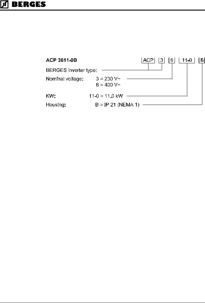
2.1Model Identification Number
All ACP 3000 models bear a systematic identification number designating the rated input voltage, the rated power and the housing type. This model number appears both on the shipping carton label and the technical data label on the drive.
Example type marking
2.2Power Specifications
|
Models with Supply Voltage 1 × |
230 VAC |
|
|
|
|
|
|
|
||||||||||||
|
|
|
|
|
|
|
|
|
|
|
|
|
|
|
|
|
|
|
|
||
|
|
|
|
Model ACP |
|
3300-3 |
3300-5 |
3300-7 |
3301-1 |
3301-5 |
3302-2 |
|
|||||||||
|
|
|
Kilowatt (kW) |
|
|
|
0.37 kW |
0.55 kW |
0.75 kW |
|
1.1 kW |
1.5 kW |
|
2.2 kW |
|
||||||
|
|
|
Output Voltage |
|
|
|
|
|
|
|
Three Phase 3.5–230 VAC |
|
|
|
|||||||
|
|
|
Rated current |
|
|
|
1.94 A |
|
2.6 A |
|
3.4 A |
|
4.8 A |
6.4 A |
|
9.0 A |
|
||||
|
|
|
Maximum Output Current * |
|
2.1 A |
|
|
2.9 A |
|
3.7 A |
|
5.3 A |
7.0 A |
|
9.9 A |
|
|||||
|
|
|
Input Volts (±10%) |
|
|
|
|
|
|
|
208–230 V~ |
|
|
|
|
||||||
|
|
|
Maximum Input Current |
|
|
3.1 A |
|
|
4.7 A |
|
6.4 A |
|
9.4 A |
12.7 A |
|
18.6 A |
|
||||
|
|
|
|
|
|
|
|
|
|
|
Table 2.1 |
|
|
|
|
|
|
|
|||
|
|
|
|
|
|
|
|
|
|
|
|
|
|
|
|
|
|
|
|||
|
|
|
|
|
|
|
|
|
|
|
|
|
|
|
|
|
|
|
|
|
|
|
Models with Supply Voltage 3 × |
400 VAC |
|
|
|
|
|
|
|
||||||||||||
|
|
|
|
|
|
|
|
|
|
|
|
|
|
|
|
|
|
|
|
|
|
|
Model ACP |
3600-7 |
|
3601-5 |
|
3602-2 |
3603-0 |
3604-0 |
3605-5 |
|
3607-5 |
3611-0 |
3615-0 |
|
|||||||
|
Kilowatt (kW) |
0.75 kW |
|
1.5 kW |
|
2.2 kW |
3.0 kW |
4.0 kW |
5.5 kW |
7.5 kW |
11.0 kW |
15.0 kW |
|
||||||||
|
Output Voltage |
|
|
|
|
|
|
Three Phase 7.0–460 VAC |
|
|
|
|
|
||||||||
|
Rated current |
1.95 A |
|
3.7 A |
|
5.2 A |
6.8 |
A |
9.2 A |
13.0 A |
18.0 A |
24.0 A |
|
30.0 A |
|
||||||
|
Maximum Output Current * |
2.1 A |
|
4.1 A |
|
5.7 A |
7.5 |
A |
10.1 A |
14.3 A |
19.8 A |
26.4 A |
|
33.0 A |
|
||||||
|
Input Volts (±10%) |
|
|
|
|
|
|
|
|
400–460 V~ |
|
|
|
|
|
||||||
|
Maximum Input Current |
2.11 A |
|
4.2 A |
|
6.2 A |
8.4 |
A |
11.2 A |
16.0 A |
22.2 A |
31.0 A |
|
37.9 A |
|
||||||
|
|
|
|
|
|
|
|
Table 2.2 |
|
|
|
|
|
|
|
|
|
|
|
||
|
|
|
|
|
|
|
|
|
|
|
|
|
|
|
|||||||
|
|
|
|
|
|
|
|
||||||||||||||
|
|
* = Maximum inverter capacity. Value = |
1.1 × 03-IRAT (see page 35). |
|
|
|
|
||||||||||||||
6 |
Operating manual |
21.12.98 |
|
ACP 3000 — 0.37–15.0 |
04_GB |
||
|
|||
|
|
|
Berges electronic • D–51709 Marienheide-Rodt • Tel. 02264/17-0 • Fax 02264/17126
2.3General Drive Specifications
|
|
|
|
|
|
|
Inverter |
Input Frequency |
|
50/60 Hz (±2%) |
|
|
Power Ratings |
|
|
|
|
|
Phase Imbalance (3 only) |
|
±2% |
|
|
|
|
|
|
||
|
|
|
|
|
|
|
|
Overload Capacity |
|
150% for 60 seconds |
|
|
|
|
|
|
|
|
|
Running Torque |
|
100% at 3 Hz |
|
|
|
|
|
|
|
|
|
Starting Torque |
|
Greater than 100% |
|
|
Control |
Control System |
|
Sine-weighted voltage vector (PWM) |
|
|
Specifications |
|
|
|
|
|
PWM Frequency |
|
4–16 kHz (plus Autoselect feature) |
|
|
|
|
|
|
||
|
|
|
|
|
|
|
|
Frequency Range |
|
1.00–400.0 Hz programmable in 0.05 Hz increments |
|
|
|
|
|
(0.1 Hz above 99.95 Hz) |
|
|
|
|
|
|
|
|
|
Frequency resolution |
|
0.05 Hz up 0.00 to 99.95 Hz, |
|
|
|
|
|
0.1 Hz above 100.0 Hz |
|
|
|
|
|
|
|
|
|
Minimum Frequency |
|
0.00–400.0 Hz |
|
|
|
|
|
|
|
|
|
Maximum Frequency |
|
20.00–400.0 Hz |
|
|
|
|
|
|
|
|
|
Preset Speeds |
|
Up to 8 available; programmable to maximum frequency |
|
|
|
|
|
|
|
|
|
Frequency Command |
0–5 VDC, 0–10 VDC, 0–20 mA, 4–20 mA, direct or inverted; |
|
|
|
|
Selections |
Digital Keypad; Program Memory Unit; Remote Keypad Unit; |
|
|
|
|
|
|
external Potentiometer |
|
|
|
|
|
|
|
|
|
Acceleration and Deceleration |
|
Programmable 0.1 to 600 seconds to maximum frequency |
|
|
|
Range |
|
(2 Each) |
|
|
|
|
|
|
|
|
|
V/Hz Ratio |
|
0.19–9.23 V/Hz (230 VAC models) |
|
|
|
|
|
0.39–18.46 V/Hz (400 VAC models) |
|
|
|
|
|
|
|
|
|
Torque Limit |
|
Automatic or fixed adjustment possible |
|
|
|
|
|
|
|
|
|
Dynamic Braking |
Up to 60% for 6 sec. with standard DB resistor; higher braking |
|
|
|
|
|
power values can be achieved by means of an external braking |
|
|
|
|
|
|
chopper (option) |
|
|
Protection |
Ground Fault |
|
Protected from damage |
|
|
Features |
|
|
|
|
|
Short Circuit |
|
Protected from damage |
|
|
|
|
|
|
||
|
|
|
|
|
|
|
|
Motor Overload |
|
Programmable inverse time overload trip |
|
|
|
|
|
|
|
|
|
Torque Limit |
|
All four quadrants individually programmable |
|
|
|
|
|
|
|
|
|
Overvoltage |
Short voltage peaks are bridged; an error is triggered if an ov- |
|
|
|
|
|
|
ervoltage lasts for longer than 500 ms |
|
|
|
|
|
|
|
|
|
Undervoltage |
Short voltage dips are bridged; a defined “Restart” is performed |
|
|
|
|
|
|
if an undervoltage lasts for longer than 200 ms |
|
|
|
|
|
|
|
|
|
Over Temperature |
|
Protected from damage, warning display |
|
|
|
|
|
|
|
|
|
MOL Input Terminal |
|
Programmable for N.C. or N.O. contacts |
|
|
Operating |
Operating Controls |
1. |
Keypad. |
|
|
Features |
|
2. |
Remote keypad unit. |
|
|
|
|
3. |
Terminal strip. |
|
|
|
|
4. |
Program memory unit. |
|
|
|
|
|
|
|
21.12.98 |
Operating manual |
7 |
|
04_GB |
ACP 3000 — 0.37–15.0 |
||
|
|||
|
|
|

Berges electronic • D–51709 Marienheide-Rodt • Tel. 02264/17-0 • Fax 02264/17126
|
|
|
|
|
|
|
Operating |
LED Indicators |
Red and Green for operation and fault annunciation |
|
|||
Features |
|
|
|
|
|
|
Keypad Display |
6 digit, backlit LCD with special annunciators |
|
|
|||
|
|
|
||||
|
|
|
|
and unit symbols |
|
|
|
|
|
|
|
|
|
|
Auxiliary Relay |
|
Programmable analog output; |
|
|
|
|
|
|
programmable status signalling relay |
|
|
|
|
|
|
|
|
|
|
|
Programming Levels |
|
|
Level 1 – Operator |
|
|
|
|
|
|
Level 2 – Engineer |
|
|
Inputs/Outputs |
Inputs |
6 Digital: |
Pull-up or pull-down logic |
|
|
|
|
|
2 Analog: VIN1 Current or voltage; |
|
|
||
|
|
|
VIN2 Voltage only |
|
|
|
|
|
|
|
|
||
|
Outputs |
2 Digital: |
1 Open collector (internal or external power supply) |
|
||
|
|
|
up to 24 VDC; |
|
|
|
|
|
|
1 Relay (Form C) |
|
|
|
|
|
2 Analog: MET1 (0 to 10 VDC); |
|
|
||
|
|
|
MET2 (0/4 to 20 mA DC) |
|
|
|
Ambient |
Operating Temperature |
|
0 °C to +40 °C (IP 21 models) |
|
|
|
Conditions |
|
|
0 °C to +50 °C (with detached cover) |
|
|
|
|
|
|
|
|
|
|
|
Storage temperature |
|
|
-20 °C to +60 °C |
|
|
|
|
|
|
|
|
|
|
Humidity |
|
90% RH or less, non-condensing |
|
|
|
|
|
|
|
|
|
|
|
Vibration |
|
|
0.6 G Maximum |
|
|
|
|
|
|
|
|
|
|
Elevation |
|
1000 Meters (3,300 Feet) without derating |
|
|
|
UL-/CSA- |
Agency Listings |
|
U |
U |
|
|
|
|
Marked, ® L |
C ® L UL/cUL listed, CSA-certified |
® |
|
|
Certifications |
|
|
|
|||
|
|
|
|
|
|
|
|
|
Table 2.3 |
|
|
|
|
|
|
|
|
|
|
|
|
|
|
|
|
|
|
2.4Dimensional Data (Size I)
6 |
105 |
123 |
5 |
94 |
3 |
137
159 |
|
|
|
|
5.5 |
|
|
12 |
|
|
|
|
22 |
|
|
|
Size I for devices: |
||
84 |
ACP 3300-3 |
(230 V) |
|
ACP 3300-5 |
(230 V) |
||
|
|||
|
ACP 3600-7 |
(400 V) |
|
30 |
Weight: 1.4 kg |
||
|
34 |
|
|
8 |
Operating manual |
21.12.98 |
|
ACP 3000 — 0.37–15.0 |
04_GB |
||
|
|||
|
|
|

Berges electronic • D–51709 Marienheide-Rodt • Tel. 02264/17-0 • Fax 02264/17126
2.4.1Dimensional Data (Size II)
6 |
140 |
125 |
5 |
129 |
3 |
137
159
 5.5
5.5
12
22
Size II for devices:
84
ACP 3300-7 (230 V)
ACP 3301-1 (230 V)
ACP 3601-5 (400 V)
38 |
|
|
|
Weight: 1.9 kg |
|
|
|
 54
54
2.4.2Dimensional Data (Size III)
140 |
|
|
|
|
|
153 |
|
|
|
|
|
|
|
|
|
|
|||
129 |
|
|
|
5 |
|
|
|||
|
|
|
|
|
|||||
|
|
|
|
|
|
|
|
|
|
220
188
 5.5
5.5
|
29 |
|
|
5 |
22 |
|
|
|
|
|
|
|
Size III for devices: |
|
|
119 |
ACP 3301-5 |
(230 |
V) |
ACP 3302-2 |
(230 |
V) |
|
|
ACP 3602-2 |
(400 |
V) |
|
ACP 3603-0 |
(400 |
V) |
|
ACP 3604-0 |
(400 |
V) |
41 |
|
|
|
|
|
|
|
Weight: 3.45 kg |
|
|
|
|
|
|
|
||
|
|
|
|
|
|
|
47 |
|
|
|
|
||||||
21.12.98 |
Operating manual |
9 |
|
04_GB |
ACP 3000 — 0.37–15.0 |
||
|
|||
|
|
|
Berges electronic • D–51709 Marienheide-Rodt • Tel. 02264/17-0 • Fax 02264/17126
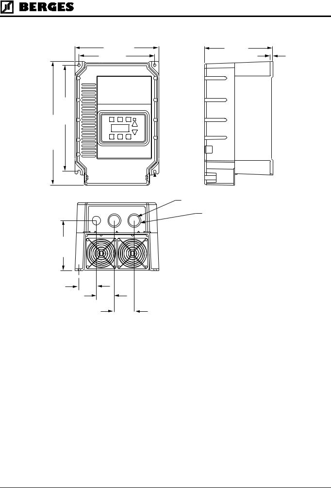
2.4.3Dimensional Data (Size IV)
221
200
280
327
133
46
47
53
180
6
 5.5
5.5
29
35
Size IV for devices:
ACP 3605-5 |
(400 V) |
ACP 3607-5 |
(400 V) |
ACP 3611-0 |
(400 V) |
ACP 3615-0 |
(400 V) |
Weight: 8.6 kg
10 |
Operating manual |
21.12.98 |
|
ACP 3000 — 0.37–15.0 |
04_GB |
||
|
|||
|
|
|
Berges electronic • D–51709 Marienheide-Rodt • Tel. 02264/17-0 • Fax 02264/17126
3Installation
3.1Inspection
A.Upon receipt, unpack and carefully inspect for any damage sustained in transit (depression in the enclosure, damage to parts, missing parts).
B.Remove the cover (see page 25) and inspect the inverter for any apparent damage or foreign objects. Ensure that all mounting hardware and terminal connection hardware is properly seated, securely fastened, and undamaged.
C.Read the technical data label and ensure that the correct rated output and input voltage for the application has been purchased.
D.If the inverter is to be stored for a long period of time, repack and store in a clean, dry place, free from direct sunlight or corrosive fumes, and in a location where the ambient temperature will not be less then -20 °C nor more than +60 °C.
3.2General Rules for Installation
Improper installation of the inverter will greatly effect its life. Be sure to observe the following points when selecting a mounting location. VIOLATING THE CONDITIONS LISTED BE-
LOW MAY VOID THE WARRANTY!
A.Mount the unit vertically and do not restrict the airflow to the heat sink fins on the back of the controller. The fan and fins allow cooling of internal components. Any air restriction could greatly reduce the life of the inverter, as well as resulting in nuisance overtemperature trips.
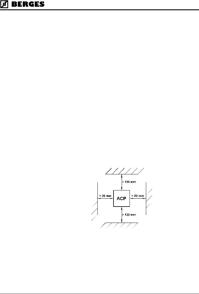
B.The ACP inverter generates heat, and therefore there must be a sufficient amount of free space around the unit (see Figure 3.1). If the unit is accommodated in a housing together with a different unit, the prescribed minimum distances must be observed so that adequate ventilation can be ensured.
Figure 3.1
C.If the inverter has to be installed in a different position, external cooling is required for full capacity utilization. In certain circumstances, the internal air circulation does not suffice when installing the unit in a control cabinet with a small volume. Therefore, when installing the unit, you must ensure that a heat buildup is prevented.
D.Do not mount the ACP near heat generating equipment, or in direct sunlight. BERGES inverters are generally designed so that they can be operated at ambient temperatures of 0 °C to +50 °C (IP 00) or 0 °C to 40 °C(IP 21) and at a relative humidity of up to 90%.
The occurrence of condensate must be avoided!
21.12.98 |
Operating manual |
11 |
|
04_GB |
ACP 3000 — 0.37–15.0 |
||
|
|||
|
|
|

Berges electronic • D–51709 Marienheide-Rodt • Tel. 02264/17-0 • Fax 02264/17126
E. Do not install the inverter in a place subjected to high temperature, high humidity, or excessive vibration (see Table 2.3, “Ambient Conditions”)
F. The units should never be installed in the proximity of corrosive or flammable gases, conductive dust or large magnetic and electric fields.
G. Pay close attention during installation to ensuring that no objects (such as drilling swarf, wire or anything else) fall into the unit. Otherwise, a device fault cannot be excluded, even after longer periods of operation.
ATTENTION!
H. Do not use wire end ferrules for the control terminals. The terminals are designed so that the wires can be inserted in the terminals after twisting the individual wires.
I.Table 3.1 shows the watts generated by the inverter when at full current. The heat generated is dependent on the carrier frequency used. For carrier frequencies other than those shown in Table 3.1, consult BERGES or use the worst-case scenario (16 kHz carrier).
HEAT GENERATED BY INVERTER (IN WATTS)
Inverter Model Number |
@ 4 kHz Carrier |
@ 16 kHz Carrier |
3300-3 |
19 |
27 |
3300-5 |
37 |
42 |
3300-7 |
66 |
75 |
3301-1 |
66 |
75 |
3301-5 |
70 |
79 |
3302-2 |
129 |
154 |
3600-7 |
40 |
62 |
3601-5 |
67 |
99 |
3602-2 |
118 |
186 |
3603-0 |
184 |
281 |
3604-0 |
184 |
281 |
3605-5 |
280 |
640 |
3607-5 |
360 |
790 |
3611-0 |
470 |
1120 |
3615-0 |
610 |
1400 |
|
Table 3.1 |
|
3.3EMC (Electromagnetic Compatibility)
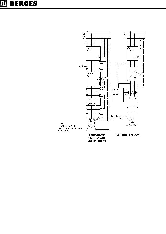
3.3.1Suggestion on how to solve the Problem of Radio Frequency Interference Suppression of Frequency Converters to VDE 0875/EN 55011
It is necessary to connect a mains filter type “BE/(xxx) xxxx” before every frequency converter. The size (xxx) depends on the rated current of the unit. A motor choke can be dispensed with.
HINT!
The motor choke type BV... may be necessary as from a cable length in excess of 20 m and when operating several motors in parallel on one frequency converter output. This choke attenuates the capacitive earth leakage currents and considerably reduces wire-borne interference voltages.
12 |
Operating manual |
21.12.98 |
|
ACP 3000 — 0.37–15.0 |
04_GB |
||
|
|||
|
|
|
Berges electronic • D–51709 Marienheide-Rodt • Tel. 02264/17-0 • Fax 02264/17126
The converter and accessories must be wired in accordance with the following schematic. To render the remaining interference voltage at the PE conductor potential ineffective for “external measurement systems”, the followingproposed circuit will achieve successful results if applied consistently.
3.3.2Mains Filters/Output Chokes
|
|
|
|
|
|
|
|
|
|
|
|
|
ACP 3000 |
|
|
|
|
|
|
DEVICE TYPE |
MAINS FILTER |
ARTICLE NO. |
INPUT PHASES |
VOLTAGE (V) |
CURRENT (A) |
WEIGHT (kg) |
FOOTPRINT |
|
|
ACP 3300-3 |
BE I 1005 |
32501739 |
1~ |
250 |
5 |
0.60 |
(1) |
|
|
|
|
|
|
|
|
|
|
|
|
ACP 3300-5 |
BE I 1005 |
32501739 |
1~ |
250 |
5 |
0.60 |
(1) |
|
|
ACP 3300-7 |
BE II 1010 |
32501740 |
1~ |
250 |
10 |
0.70 |
(1) |
|
|
ACP 3301-1 |
BE II 1010 |
32501740 |
1~ |
250 |
10 |
0.70 |
(1) |
|
|
ACP 3301-5 |
BE III 1020 |
32501741 |
1~ |
250 |
20 |
1.05 |
(1) |
|
|
ACP 3302-2 |
BE III 1020 |
32501741 |
1~ |
250 |
20 |
1.05 |
(1) |
|
|
ACP 3600-7 |
BE I 3003 |
32501742 |
3~ |
380/480 |
3 |
0.75 |
(1) |
|
|
ACP 3601-5 |
BE II 3005 |
32501743 |
3~ |
380/480 |
5 |
0.80 |
(1) |
|
|
ACP 3602-2 |
BE III 3012 |
32501744 |
3~ |
380/480 |
12 |
1.15 |
(1) |
|
|
ACP 3603-0 |
BE III 3012 |
32501744 |
3~ |
380/480 |
12 |
1.15 |
(1) |
|
|
ACP 3604-0 |
BE III 3012 |
32501744 |
3~ |
380/480 |
12 |
1.15 |
(1) |
|
|
ACP 3605-5 |
BE IV 3038 |
32501745 |
3~ |
380/480 |
38 |
1.90 |
(1) |
|
|
ACP 3607-5 |
BE IV 3038 |
32501745 |
3~ |
380/480 |
38 |
1.90 |
(1) |
|
|
ACP 3611-0 |
BE IV 3038 |
32501745 |
3~ |
380/480 |
38 |
1.90 |
(1) |
|
|
ACP 3615-0 |
BE IV 3038 |
32501745 |
3~ |
380/480 |
38 |
1.90 |
(1) |
|
|
|
|
|
|
|
|
|
|
|
|
|
|
|
|
|
|
|
|
|
|
|
(1) FOOTPRINT means that these filters have been prepared for the installation of an ACP converter on the filter (securing). |
|
|
|
|
|
|
21.12.98 |
Operating manual |
13 |
|
04_GB |
ACP 3000 — 0.37–15.0 |
||
|
|||
|
|
|

Berges electronic • D–51709 Marienheide-Rodt • Tel. 02264/17-0 • Fax 02264/17126
ACP 3000
DEVICE TYPE |
CHOKE |
ARTICLE NO. |
INPUT PHASES |
VOLTAGE (V) |
CURRENT (A) |
WEIGHT (kg) |
|
|
FOOTPRINT |
||||||||||||||||||||||
ACP 3300-3 |
BV 20394/307 |
32501345 |
|
|
|
– |
440 |
7 |
|
|
|
|
|
|
0.25 |
|
|
|
|
|
|
|
|
– |
|||||||
ACP 3300-5 |
BV 20394/307 |
32501345 |
|
|
|
– |
440 |
7 |
|
|
|
|
|
|
0.25 |
|
|
|
|
|
|
|
|
– |
|||||||
ACP 3300-7 |
BV 20394/307 |
32501345 |
|
|
|
– |
440 |
7 |
|
|
|
|
|
|
0.25 |
|
|
|
|
|
|
|
|
– |
|||||||
ACP 3301-1 |
BV 20394/307 |
32501345 |
|
|
|
– |
440 |
7 |
|
|
|
|
|
|
0.25 |
|
|
|
|
|
|
|
|
– |
|||||||
ACP 3301-5 |
BV 20394/307 |
32501345 |
|
|
|
– |
440 |
7 |
|
|
|
|
|
|
0.25 |
|
|
|
|
|
|
|
|
– |
|||||||
ACP 3302-2 |
BV 20394/313 |
32501346 |
|
|
|
– |
440 |
13 |
|
|
|
|
|
|
0.70 |
|
|
|
|
|
|
|
|
– |
|||||||
ACP 3600-7 |
BV 20394/307 |
32501345 |
|
|
|
– |
440 |
7 |
|
|
|
|
|
|
0.25 |
|
|
|
|
|
|
|
|
– |
|||||||
ACP 3601-5 |
BV 20394/307 |
32501345 |
|
|
|
– |
440 |
7 |
|
|
|
|
|
|
0.25 |
|
|
|
|
|
|
|
|
– |
|||||||
ACP 3602-2 |
BV 20394/307 |
32501345 |
|
|
|
– |
440 |
7 |
|
|
|
|
|
|
0.25 |
|
|
|
|
|
|
|
|
– |
|||||||
ACP 3603-0 |
BV 20394/307 |
32501345 |
|
|
|
– |
440 |
7 |
|
|
|
|
|
|
0.25 |
|
|
|
|
|
|
|
|
– |
|||||||
ACP 3604-0 |
BV 20394/313 |
32501346 |
|
|
|
– |
440 |
13 |
|
|
|
|
|
|
0.70 |
|
|
|
|
|
|
|
|
– |
|||||||
ACP 3605-5 |
BV 20394/313 |
32501346 |
|
|
|
– |
440 |
13 |
|
|
|
|
|
|
0.70 |
|
|
|
|
|
|
|
|
– |
|||||||
ACP 3607-5 |
BV 20394/325 |
32501347 |
|
|
|
– |
440 |
25 |
|
|
|
|
|
|
1.10 |
|
|
|
|
|
|
|
|
– |
|||||||
ACP 3611-0 |
BV 20394/325 |
32501347 |
|
|
|
– |
440 |
25 |
|
|
|
|
|
|
1.10 |
|
|
|
|
|
|
|
|
– |
|||||||
ACP 3615-0 |
BV 20394/330 |
32501348 |
|
|
|
– |
440 |
30 |
|
|
|
|
|
|
1.15 |
|
|
|
|
|
|
|
|
– |
|||||||
|
|
|
|
|
|
|
|
|
|
|
|
|
|
|
|
|
|
|
|
|
|
|
|
|
|
|
|
|
|
|
|
|
|
|
|
|
|
|
|
|
|
|
|
|
|
|
|
|
|
|
|
|
|
|
|
|
|
|
|
|
|
|
|
|
|
|
|
|
|
|
|
|
|
|
|
|
|
|
|
|
|
|
|
|
|
|
|
|
|
|
|
|
|
|
|
|
|
|
|
|
|
|
|
|
|
|
|
|
|
|
|
|
|
|
|
|
|
|
|
|
|
|
|
|
|
|
|
|
|
|
|
|
|
|
|
|
|
|
|
|
|
|
|
|
|
|
|
|
|
|
|
|
|
|
|
|
|
|
|
|
|
|
|
|
|
|
|
|
|
|
|
|
|
|
|
|
|
|
|
|
|
|
|
|
|
|
|
|
|
|
|
|
|
|
|
|
|
|
|
|
|
|
|
|
|
|
|
|
|
|
|
|
|
|
|
|
|
|
|
|
|
|
|
|
|
|
|
|
|
|
|
|
|
|
|
|
|
|
|
|
|
|
|
|
|
|
|
|
|
|
|
|
|
|
|
|
|
|
|
|
|
|
|
|
|
|
|
|
|
|
|
|
|
|
|
|
|
|
|
|
|
|
|
|
|
|
|
|
|
|
|
|
|
|
|
|
|
|
|
|
|
|
|
|
|
|
|
|
|
|
|
|
|
|
|
|
|
|
|
|
|
|
|
|
|
|
|
|
|
|
|
|
|
|
|
|
|
|
|
|
|
|
|
|
|
|
|
|
|
|
|
|
|
|
|
|
|
|
|
|
|
|
|
|
|
|
|
|
|
|
|
|
|
|
|
|
|
|
|
|
|
|
|
|
|
|
|
|
|
|
|
|
|
|
|
|
|
|
|
|
|
|
|
|
|
|
|
|
|
|
|
|
|
|
|
|
|
|
|
|
|
|
|
|
|
|
|
|
|
|
|
|
|
|
|
|
|
|
|
|
|
|
|
|
|
|
|
|
|
|
|
|
|
|
|
|
|
|
|
|
|
|
|
|
|
|
|
|
|
|
|
|
|
|
|
|
|
|
|
|
|
|
|
|
|
|
|
|
|
|
|
|
|
|
|
|
|
|
|
|
|
|
|
|
|
|
|
|
|
|
|
|
|
|
|
|
|
|
|
|
|
|
|
|
|
|
|
|
|
|
|
|
|
|
|
|
|
|
|
|
|
|
|
|
|
|
|
|
|
|
|
|
|
|
|
|
|
|
|
|
|
|
|
|
|
|
|
|
|
|
|
|
|
|
|
|
|
|
|
|
|
|
|
|
|
|
|
|
|
|
|
|
|
|
|
|
|
|
|
|
|
|
|
|
|
|
|
|
|
|
|
|
|
|
|
|
|
|
|
|
|
|
|
|
|
|
|
|
|
|
|
|
|
|
|
|
|
|
|
|
|
|
|
|
|
|
|
|
|
|
|
|
|
|
|
|
|
|
|
|
|
|
|
|
|
|
|
|
|
|
|
|
|
|
|
|
|
|
|
|
|
|
|
|
|
|
|
|
|
|
|
|
|
|
|
|
|
|
|
|
|
|
|
|
|
|
|
|
|
|
|
|
|
|
|
|
|
|
|
|
|
|
|
|
|
|
|
|
|
|
|
|
|
|
|
|
|
|
|
|
|
|
|
|
|
|
|
|
|
|
|
|
|
|
|
|
|
|
|
|
|
|
|
|
|
|
|
|
|
|
|
|
|
|
|
|
|
|
|
|
|
|
|
|
|
|
|
|
|
|
|
|
|
|
|
|
|
|
|
|
|
|
|
|
|
|
|
|
|
|
|
|
|
|
|
|
|
|
|
|
|
|
|
|
|
|
|
|
|
|
|
|
|
|
|
|
|
|
|
|
|
|
|
|
|
|
|
|
|
|
|
|
|
|
|
|
|
|
|
|
|
|
|
|
|
|
|
|
|
|
|
|
|
|
|
|
|
|
|
|
|
|
|
|
|
|
|
|
|
|
|
|
|
|
|
|
|
|
|
|
|
|
|
|
|
|
|
|
|
|
|
|
|
|
|
|
|
|
|
|
|
|
|
|
|
|
|
|
|
|
|
|
|
|
|
|
|
|
|
|
|
|
|
|
|
|
|
|
|
|
|
|
|
|
|
|
|
|
|
3.3.3Filter Specifications
All BERGES line filters are provided in IP20 enclosures. They can operate over a temperature range of -10 to +50 °C (-23 to +122 °F). The filters can be mounted parallel or perpendicular to the control panel. The filter is supplied with the correct mounting hardware for mounting the inverter on top of the filter enclosure (Footprint).
ATTENTION!
The mains filters and chokes must be installed and connected in conformity with the recommendations given in chapters 3.3.1 (page 12), 3.3.4 (page 15) and 3.6.3 (page 22).
14 |
Operating manual |
21.12.98 |
|
ACP 3000 — 0.37–15.0 |
04_GB |
||
|
|||
|
|
|

Berges electronic • D–51709 Marienheide-Rodt • Tel. 02264/17-0 • Fax 02264/17126
|
|
|
|
|
|
|
|
|
|
|
|
|
|
|
|
|
|
|
|
TYPE |
OUTER DIMENSIONS |
|
SECURING |
SECURING ON THE |
CONNECTIONS |
FOOT- |
|
||||||||||
|
|
|
|
|
|
|
|
|
|
|
INVERTER |
|
|
|
|
|||
|
|
A |
B |
C |
D |
|
E |
|
F |
G |
|
H |
|
I |
J (PE) |
K |
|
|
|
BE I 1005 |
200 |
108 |
40 |
183 |
|
80 |
|
M5 |
137 |
|
94 |
|
M5 |
M4 |
2,5 mm2 |
(1) |
|
|
BE II 1010 |
200 |
145 |
40 |
183 |
|
110 |
|
M5 |
137 |
|
129 |
|
M5 |
M4 |
2,5 mm2 |
(1) |
|
|
BE III 1020 |
250 |
145 |
45 |
235 |
|
110 |
|
M5 |
188 |
|
129 |
|
M5 |
M4 |
2,5 mm2 |
(1) |
|
|
BE I 3003 |
200 |
108 |
40 |
183 |
|
80 |
|
M5 |
137 |
|
94 |
|
M5 |
M4 |
2,5 mm2 |
(1) |
|
|
BE II 3005 |
200 |
145 |
40 |
183 |
|
110 |
|
M5 |
137 |
|
129 |
|
M5 |
M4 |
2,5 mm2 |
(1) |
|
|
BE III 3012 |
250 |
145 |
45 |
235 |
|
110 |
|
M5 |
188 |
|
129 |
|
M5 |
M5 |
2,5 mm2 |
(1) |
|
|
BE IV 3038 |
360 |
222 |
50 |
342 |
|
160 |
|
M6 |
280 |
|
200 |
|
M6 |
M5 |
16 mm2 |
(1) |
|
|
BE V 3012 |
360 |
222 |
50 |
342 |
|
160 |
|
M6 |
280 |
|
200 |
|
M6 |
M5 |
16 mm2 |
(1) |
|
|
BE VI 3040 |
496 |
232 |
50 |
478 |
|
180 |
|
M6 |
419 |
|
200 |
|
M6 |
M5 |
16 mm2 |
(1) |
|
|
|
|
|
|
|
|
|
Table 3.2 |
|
|
|
|
|
|
|
|
|
|
|
|
|
|
|
|
|
|
|
|
|
|
|
|
|
|
|
|
|
|
|
|
|
|
|
|
|
|
|
|
|
|
|
|
|
|
|
|
NOTE: Dimensions in mm.
3.3.4Interference Suppression Measures
|
Electrical/electronic devices are capable of influencing or disturbing each other through |
|||
|
connecting cables or other metallic connections. “Electromagnetic compatibility” consists of |
|||
|
the factors “interference resistance” and “interference emission”Correct. |
installation of |
||
|
the inverter in conjunction with any possible local interference suppression meas- |
|||
|
ures has a crucial effect on minimizing or suppressing mutual interference. |
|||
|
|
|
||
|
(1) FOOTPRINT means that these filters have been prepared for the installation of an ACP converter on the filter (securing). |
|||
|
|
|
|
|
21.12.98 |
Operating manual |
15 |
|
|
04_GB |
ACP 3000 — 0.37–15.0 |
|
|
|
|
|
|
||
|
|
|
|
|

Berges electronic • D–51709 Marienheide-Rodt • Tel. 02264/17-0 • Fax 02264/17126
The scope of noise suppression measures depends on the limit value class, the local situation and the application.
The following notes refer to a mains power supply that is not “contaminated” by high frequency interference. Other measures may be necessary to reduce or suppress interference if the mains voltage is “contaminated”. Nogenerally valid recommendations can be given in such cases. Please consult BERGES if all recommended interference suppression measures should not produce the desired result.
Basically, it is not the cross section of the conductor that is important for radio-frequency interference suppression but the surface area. Since the high-frequency interference does not flow through the entire cross section but mainly on the outer surface of the conductor (skin effect), braided copper tapes of corresponding cross section should be used.
All conductive housing parts must be interconnected using corresponding lines. Minimum cross sections are prescribed for a fault case at 50 Hz (referred to the range of the safety regulations) which must be observed under all circumstances.
The inverter and all other components used for interference suppression (especially also the shield of the motor cable) should be contacted over as large an area as possible when connected to metal (control panels, switchgear cabinets and similar) (skin effect). Remove the paint at the respective areas to ensure good contacting over a large area!
A central earthing point should be used for interference suppression (e.g. equipotential bonding strip or centrally at an interference suppression filter). The earthing lines are routed to the respective terminals radially from this point. Conductor loops of the earthing lines are impermissible and can lead to unnecessary interference.
The shield cross section must not be reduced when the shield is connected to continuing lines. This would give rise to RF resistance at a cross section reduction, and the resulting RF energy would consequently not be discharged but radiated. Shields – particularly shields of control lines – must not be contacted via pin contacts of plug connectors. In these cases, the metallic hand guard of the plug connector should be used for large-area connection of the shield.
Use a shielded motor cable (earthed over a large area at both sides). The shield should be routed uninterrupted from the PE terminal of the inverter to the PE terminal of the motor. If a shielded motor line cannot be used, the unshielded motor line should be laid in a metal duct. The metal duct must be uninterrupted and adequately earthed. The following points are prescribed if radio interference suppression is to be realized in accordance with EN 55011, EN 55014 and EN 50081-1:
•Preceding the unit by a mains filter or a mains filter and a output choke (mains filter and output choke not included in the scope of delivery).
•Laying the motor cable in a shielded configuration.
•Laying the control cable in a shielded configuration.
•Observe general RFI suppression measures (refer to the chapters 3.3.1 and 3.3.4).
Lay motor, mains power and signal cables as far away from each other as possible and separately.
If a mains filter is used, the smallest possible spatial distance from the frequency inverter must be selected so that both units can be connected by short connection leads.
If an output choke is used (option), it must be fitted in the direct vicinity of the inverter and connected to the inverter via screened cables earthed at both ends.
Shielded signal cables should be laid at a minimum distance of 10 cm from power cables running parallel. A separate earthed metal cable duct is advisable for such signal cables. If signal cables intercept with a power cable, they should do so at an angle of 90°.
16 |
Operating manual |
21.12.98 |
|
ACP 3000 — 0.37–15.0 |
04_GB |
||
|
|||
|
|
|
Berges electronic • D–51709 Marienheide-Rodt • Tel. 02264/17-0 • Fax 02264/17126
Control lines longer than 1 m must be laid with a shield and earthed at one side on the frequency inverter. The screen is earthed via terminal “CM” in the case of pull-up logic and pull-down logic (see “Connection Diagrams”, chapters 7.1 to 7.7). If cables have lengths in excess of 10 m, use a 0–20 mA control signal because of the possibility of parasitics. The inverter can be switched over to this mode of operation. See parameter 24-FSEL (chapter 5.2, page 38).
Other loads connected to the mains may produce voltage spikes that may interfere with functioning of the inverter or may even damage it. Chokes or mains filters can be used on the mains side to protect the inverter against voltage spikes (resulting from switching large loads to the mains). Such chokes and filters are available as accessories.
If inverters are operated in switchgear devices or in their close proximity (e.g. in one common control cabinet) in connection with the same power mains, we recommend the following precautionary measures to suppress interference in the switchgear:
•Wire the coils of contactors, switchgear devices and relay combinations with “RC elements” or with free-wheel diodes.
•Use shielded cables for external control and measuring cables.
•Lay disturbing cables (e.g. power and contactor control circuits) separately and at a distance from the control cables.
3.4EMC Ordinance (EMC Directive, 89/336 EEC)
The frequency inverters were tested in the form of a practical test set-up in a switchgear cabinet (in accordance with our interference suppression measures in these operating instructions: “EMC (electromagnetic compatibility)”. The limit values of the standards below were fulfilled under these conditions:
EMA (Electromagnetic Emission)
EN 50081-1 Basic specification “Emitted interference” (Limit value class A) or
EN 50081-2 Basic specification “Emitted interference” (Limit value class B) EN 55011 Emitted interference
EMB (Electromagnetic Interference)
EN 50082-2 Basic specification “Interference immunity”
EN 50140 Electromagnetic fields
EN 60801 Static discharge (ESD)
IEC 801-4 Burst on mains lead/data line
HINT!
At least the following conditions must be fulfilled for compliance with the limit values of the aforementioned standards:
•Installation of a mains filter or a mains filter and a motor choke (mains filter and motor choke are not included in the scope of delivery).
•Laying the motor cable in a shielded configuration.
•Laying the control cable in a shielded configuration.
•Observe general RFI suppression measures (refer to the chapters 3.3.1 and 3.3.4).
As the aforementioned interference resistance tests are based on standardised mains conditions, in extreme cases it may happen that the function of the inverter will be lost (minimum operating quality). This malfunction can generally be remedied by a RESET of the inverter. Refer to the chapter entitled “Resetting a Fault” and “Fault Codes” on page 63.
Detailed information and technical data relating to adapted mains filters and chokes can be found in the chapters 3.3.2, “Mains Filters/Output Chokes” and 3.3.3, “Filter Specifications”.
21.12.98 |
Operating manual |
17 |
|
04_GB |
ACP 3000 — 0.37–15.0 |
||
|
|||
|
|
|

Berges electronic • D–51709 Marienheide-Rodt • Tel. 02264/17-0 • Fax 02264/17126
3.5Wiring Practices
3.5.1Applicable Codes
Pay conscientious attention to ensuring that the installation wiring is installed at least in conformity with the NEC standards. Where local codes exceed these requirements, they must be followed.
All models are listed by the Underwriters Laboratories, Inc. (UL) and are certified by the Canadian Underwriters Laboratories (cUL) and therefore conform to the requirements of NEC and CEC. Installations that are to meet the requirements of UL and cUL must be realised in conformity with the UL and cUL specifications. Refer to the corresponding electrical data on the rating plates of the ACP 3000 unit and the motor.
3.5.2Power Wiring
Power wiring are those wires which are connected during installation to the power circuit terminals, L1, N, L2, L3, M1, M2, and M3. Power wiring must be selected as follows:
1.Use only VDE, UL or cUL recognized wire.
2.Wire voltage rating must be a minimum of 300 V for 230 VAC systems, and 600 V for 400 VAC systems.
3.The core cross section and the associated fuse are given in the tables in chapter 3.6.2, page 22. The wires must consist of copper and be designed for insulation temperatures of 60 °C or 75 °C.
4.Grounding must be in accordance with VDE, NEC and CEC.
NOTES:
ATTENTION!
Never connect input AC power to the motor output terminals M1, M2 and M3 or damage to the drive will result.
The output voltage of variable-frequency controllers contains high-frequency components that might cause disturbances in other installations. Therefore, avoid laying control cables and mains input cables in the same cable duct or conduit together with the output cables from the converter to the motor (see also chapter 3.3.4, “Interference Suppression Meas- ures”).
3.5.3Control Wiring/Interface
ATTENTION!
All interfaces or control inputs and outputs possess only basic insulation by the mains and must be incorporated in a further protective measure.
Use a dummy plug as additional protection if interface J22 is not allocated.
This is wiring connected to the control terminal strip (20 terminals). It must be selected as follows:
1.Shielded wire is recommended to prevent electrical noise interference from causing improper operation or nuisance tripping. Only connect the screen on one end to the “CM” terminal on the converter’s control terminal strip (see also chapter 3.3.4, “Interference Suppression Measures”).
2.Use only VDE, UL or cUL recognized wire.
3.Wire voltage rating must be a minimum of 300 V for 230 VAC systems, and 600 V for 400 VAC systems. This is Class 1 wire.
4.Never run the control wiring in the same conduit or raceway with power wiring.
18 |
Operating manual |
21.12.98 |
|
ACP 3000 — 0.37–15.0 |
04_GB |
||
|
|||
|
|
|

Berges electronic • D–51709 Marienheide-Rodt • Tel. 02264/17-0 • Fax 02264/17126
5.Do not use wire end ferrules for the control terminals. The terminals are designed so that the wires can be inserted in the terminals after twisting the individual wires.
3.6Mains Power Connection
The frequency inverters are designed for installation in a switchgear cabinet and for permanent connection.
To guarantee lasting operating safety and reliability, the inverter must be connected expertly in accordance with the valid electrical standards. Attention must be paid to good insulation from earth potential on the power terminals.
An AC system with a nominal voltage of 230 V (50/60 Hz) must be connected to mains terminals L1, N and PE or a three-phase system with a nominal voltage of 400 V (50/60 Hz) to terminals L1, L2, L3 and PE (pay attention to rating plate). The neutral point must be earthed (TN-C system).
Ensure a voltage balanced to earth or phase to phase when feeding in the mains power through an isolating transformer (star point must be earthed).
Frequency inverters must not be connected via a residual-current- operated circuit-breaker as the sole protective measure!
The single exception below permits connection of a frequency inverter via a residual-cur- rent-operated circuit-breaker as the sole protective measure:
•Installation of a residual-current-operated circuit-breaker of the newest design for frequency inverters up to 4 kVA (input voltage 1 × 230 V) with MOBILE connection.
This residual current-operated circuit breaker must be suitable for alternating and pulsating DC leakage current. Residual-current-operated circuit-breakers of this type bear the symbol  .
.
Reliable tripping of the residual-current-operated circuit-breaker is not ensured in the case of frequency inverters up to 4 kVA (input voltage 3 × 400 V) with MOBILE connection; an additional protective measure must be used for this reason. Also see the diagram below.
In the case of frequency inverters with PERMANENT connection (input voltage 1 × 230 V and 3 × 400 V), another protective measure must always be used in addition to the residual-current-operated protective device. Also see the diagram below.
The protective function of the residual-current-operated circuit-breaker is no longer ensured due to leakage currents from interference suppression capacitors in the inverter and DC components in the fault current. All devices connected to this residual-current-operated cir- cuit-breaker (and persons touching them) are no longer protected in the event of a fault.
21.12.98 |
Operating manual |
19 |
|
04_GB |
ACP 3000 — 0.37–15.0 |
||
|
|||
|
|
|
Loading...