


ACM D2
Operat in g man ual
ACM
D2/S2

Table of contents
1. General information. . . . . . . . . . . . . . . . . . . . . . . . . . . . . . . . . . . . . . . . . . . . . . . . . . . . . . 3
2. Safety instructions. . . . . . . . . . . . . . . . . . . . . . . . . . . . . . . . . . . . . . . . . . . . . . . . . . . . . . . 3
2.1.General safety instructions. . . . . . . . . . . . . . . . . . . . . . . . . . . . . . . . . . . . . . . . . . . 3
2.2.Intended use. . . . . . . . . . . . . . . . . . . . . . . . . . . . . . . . . . . . . . . . . . . . . . . . . . . . . . 3
2.3.Transport, storage, installation. . . . . . . . . . . . . . . . . . . . . . . . . . . . . . . . . . . . . . . . 4
2.4.Electrical connection. . . . . . . . . . . . . . . . . . . . . . . . . . . . . . . . . . . . . . . . . . . . . . . . 4
2.5.Operating instructions. . . . . . . . . . . . . . . . . . . . . . . . . . . . . . . . . . . . . . . . . . . . . . . 4
2.6.Miscellaneous. . . . . . . . . . . . . . . . . . . . . . . . . . . . . . . . . . . . . . . . . . . . . . . . . . . . . 5
3. Introduction. . . . . . . . . . . . . . . . . . . . . . . . . . . . . . . . . . . . . . . . . . . . . . . . . . . . . . . . . . . . 6
4. Technical data (input voltage 1 x 220...240V). . . . . . . . . . . . . . . . . . . . . . . . . . . . . . . . . . 7
5. Technical data (input voltage 3 x 380...460V). . . . . . . . . . . . . . . . . . . . . . . . . . . . . . . . . . 8
6. Technical data (input voltage 3 x 380...460V). . . . . . . . . . . . . . . . . . . . . . . . . . . . . . . . . . 9
7. Power-derating in function of the switching frequency. . . . . . . . . . . . . . . . . . . . . . . . . . 10
8. Dimensional data ACM D2/S2 0.37 kW - 5.5 kW. . . . . . . . . . . . . . . . . . . . . . . . . . . . . . 11
9. Dimensional data ACM D2 7.5 kW - 22.0 kW. . . . . . . . . . . . . . . . . . . . . . . . . . . . . . . . . 12
10. Dimensional data ACM D2 30.0 kW - 37.0 kW. . . . . . . . . . . . . . . . . . . . . . . . . . . . . . . . 13
11. Installation examples. . . . . . . . . . . . . . . . . . . . . . . . . . . . . . . . . . . . . . . . . . . . . . . . . . . . 14
11.1.Example 1: ACM D2/S2 0.37 kW - 2.2 kW (1 x 230V). . . . . . . . . . . . . . . . . . . . 14
11.2.Example 2: ACM D2/S2 0.75 kW - 37.0 kW (3 x 400V). . . . . . . . . . . . . . . . . . . 15
12. Installation. . . . . . . . . . . . . . . . . . . . . . . . . . . . . . . . . . . . . . . . . . . . . . . . . . . . . . . . . . . . 16
12.1.Installation. . . . . . . . . . . . . . . . . . . . . . . . . . . . . . . . . . . . . . . . . . . . . . . . . . . . . . . 16
12.2.Mains power connection. . . . . . . . . . . . . . . . . . . . . . . . . . . . . . . . . . . . . . . . . . . . 16
12.3.Motor connection. . . . . . . . . . . . . . . . . . . . . . . . . . . . . . . . . . . . . . . . . . . . . . . . . . 17
12.4.Interference suppression measures / EMC (electromagnetic compatibility). . . . . 17
12.4.1.General information. . . . . . . . . . . . . . . . . . . . . . . . . . . . . . . . . . . . . . . . . 17
12.4.2.Installation notes. . . . . . . . . . . . . . . . . . . . . . . . . . . . . . . . . . . . . . . . . . . 17
12.5.Mains back-up fuses. . . . . . . . . . . . . . . . . . . . . . . . . . . . . . . . . . . . . . . . . . . . . . . 18
12.6.Ventilation. . . . . . . . . . . . . . . . . . . . . . . . . . . . . . . . . . . . . . . . . . . . . . . . . . . . . . . 18
12.7.Control terminals. . . . . . . . . . . . . . . . . . . . . . . . . . . . . . . . . . . . . . . . . . . . . . . . . . 19
12.8.Power terminals. . . . . . . . . . . . . . . . . . . . . . . . . . . . . . . . . . . . . . . . . . . . . . . . . . 20
BERGES electronic
09.07.2001 Operating manual ACM D2/S2 1
13. Commissioning and settings . . . . . . . . . . . . . . . . . . . . . . . . . . . . . . . . . . . . . . . . . . . . . . 21
13.1. General information . . . . . . . . . . . . . . . . . . . . . . . . . . . . . . . . . . . . . . . . . . . . . . . . 21
13.2. Adaption to operation. . . . . . . . . . . . . . . . . . . . . . . . . . . . . . . . . . . . . . . . . . . . . . . 21
14. Operating functions . . . . . . . . . . . . . . . . . . . . . . . . . . . . . . . . . . . . . . . . . . . . . . . . . . . . . 22
14.1. General . . . . . . . . . . . . . . . . . . . . . . . . . . . . . . . . . . . . . . . . . . . . . . . . . . . . . . . . . 22
14.2. Control panel . . . . . . . . . . . . . . . . . . . . . . . . . . . . . . . . . . . . . . . . . . . . . . . . . . . . . 22
14.3. Display. . . . . . . . . . . . . . . . . . . . . . . . . . . . . . . . . . . . . . . . . . . . . . . . . . . . . . . . . . 23
14.4. Help - function and language - select. . . . . . . . . . . . . . . . . . . . . . . . . . . . . . . . . . . 23
14.5. Inverter status . . . . . . . . . . . . . . . . . . . . . . . . . . . . . . . . . . . . . . . . . . . . . . . . . . . . 23
14.6. Warnings . . . . . . . . . . . . . . . . . . . . . . . . . . . . . . . . . . . . . . . . . . . . . . . . . . . . . . . . 24
14.7. Operating error messages . . . . . . . . . . . . . . . . . . . . . . . . . . . . . . . . . . . . . . . . . . . 24
14.8. Hardware error messages . . . . . . . . . . . . . . . . . . . . . . . . . . . . . . . . . . . . . . . . . . . 25
15. Programming ACM D2/S2. . . . . . . . . . . . . . . . . . . . . . . . . . . . . . . . . . . . . . . . . . . . . . . . 26
15.1. Program structure . . . . . . . . . . . . . . . . . . . . . . . . . . . . . . . . . . . . . . . . . . . . . . . . . 26
15.2. Program level TAB1. . . . . . . . . . . . . . . . . . . . . . . . . . . . . . . . . . . . . . . . . . . . . . . . 28
15.3. Program level TAB2. . . . . . . . . . . . . . . . . . . . . . . . . . . . . . . . . . . . . . . . . . . . . . . . 38
15.4. Program level TAB3. . . . . . . . . . . . . . . . . . . . . . . . . . . . . . . . . . . . . . . . . . . . . . . . 43
16. Braking chopper ACM D2/S2 . . . . . . . . . . . . . . . . . . . . . . . . . . . . . . . . . . . . . . . . . . . . . 51
16.1. Braking chopper 0.37 kW - 1.1 kW (1 x 230V). . . . . . . . . . . . . . . . . . . . . . . . . . . . 51
16.2. Braking chopper 0.75 kW - 37.0 kW (3 x 400V). . . . . . . . . . . . . . . . . . . . . . . . . . . 51
16.2.1. Minimum values for braking resistors (accessory) . . . . . . . . . . . . . . . . . . 51
16.2.2. Assembling the braking resistor . . . . . . . . . . . . . . . . . . . . . . . . . . . . . . . . 51
17. Accessories . . . . . . . . . . . . . . . . . . . . . . . . . . . . . . . . . . . . . . . . . . . . . . . . . . . . . . . . . . . 52
17.1. Programming key. . . . . . . . . . . . . . . . . . . . . . . . . . . . . . . . . . . . . . . . . . . . . . . . . . 52
17.2. Telecomander RC . . . . . . . . . . . . . . . . . . . . . . . . . . . . . . . . . . . . . . . . . . . . . . . . . 53
17.3. DVM - PLUS MP . . . . . . . . . . . . . . . . . . . . . . . . . . . . . . . . . . . . . . . . . . . . . . . . . . 53
17.4. ACM - Synchronizer. . . . . . . . . . . . . . . . . . . . . . . . . . . . . . . . . . . . . . . . . . . . . . . . 53
18. Faults and remedies. . . . . . . . . . . . . . . . . . . . . . . . . . . . . . . . . . . . . . . . . . . . . . . . . . . . . 54
19. Functions of ACM D2/S2. . . . . . . . . . . . . . . . . . . . . . . . . . . . . . . . . . . . . . . . . . . . . . . . . 55
20. Notes . . . . . . . . . . . . . . . . . . . . . . . . . . . . . . . . . . . . . . . . . . . . . . . . . . . . . . . . . . . . . . . . 58
Operatin g manual ACM D2/S2
Document: ACM/D2A-STD-E/A07
Edition: 09.07.2001
© 2001 BERGES electronic s.r.l. All rights reserved.
ArtNr: 38005000EN
BERGES electronic
2 Operating manual ACM D2/S2 09.07.2001

1.General information
Before you start with the installation and the starting up of the inverter, please read this manual carefully
and pay special attention to the notes and suggestions.
This manual must be made available to every user. Before working with the unit the user must become
familiar with it. This specially applies to the knowledge a nd observance of the following safety and
warning indications.
Used symbols:
Danger, warning
This symbol is used when the life or health of the user is in danger or a considerable damage to property
can occur.
Attention, essential measure
This symbol is shown on places of the manual, which are to be particularly consid ered for safe and
disturbance-free operation of the inverter.
2.Safety instructions
All instructions stated in this chapter are important for t he security of users and machines or systems
and should absolutely be considered.
2.1.General safety instructions
Inverters work with high voltages, which can cause death or serious injury by touching them. Depending
on the degree of protection of the inverter, in operation they may have live, uninsulated and possibly
also moving or rotating parts, as well as hot surfaces. In case of an inadmissible removal of the required
covers, an improper use and a wrong installation or operation, there is a danger of serious personal
injury and damage to property.
All operations serving transport, installation and commissioning as well as maintenance are to be
carried out by skilled technical personnel (observe IEC 364 or CENELEC HD 384 and national accident
prevention rules!). For the purposes of these basic safety instructions, "skilled technical personnel"
means persons who are familiar with the installation, mounting, commissioning and operation of the
product and have the qualifications needed for the performance of their functions.
2.2.Intended use
The application of the inverter described in this operating manual exclusively serves for the purpose
of continuously variable speed control of three-phase motors.
Inverters are components designed to be used in electrical installations or machinery.
Commissioning of the inverter (e.g. the starting of normal operation) is prohibited until the system has
been proved to conform to the provisions of the directive 89/392/EEC (Machinery Safety Directive -
MSD) and the 89/336/EEC (EMC directive).
The inverter meets the requirements of the low-voltage directive 73/231/EEC. They are subject to the
harmonized standards of the series EN 50178.
The operator of the system is solely liable for damage resulting from improper use of the inverter.
ATTENTION!
BERGES electronic
09.07.2001 Operating manual ACM D2/S2 3
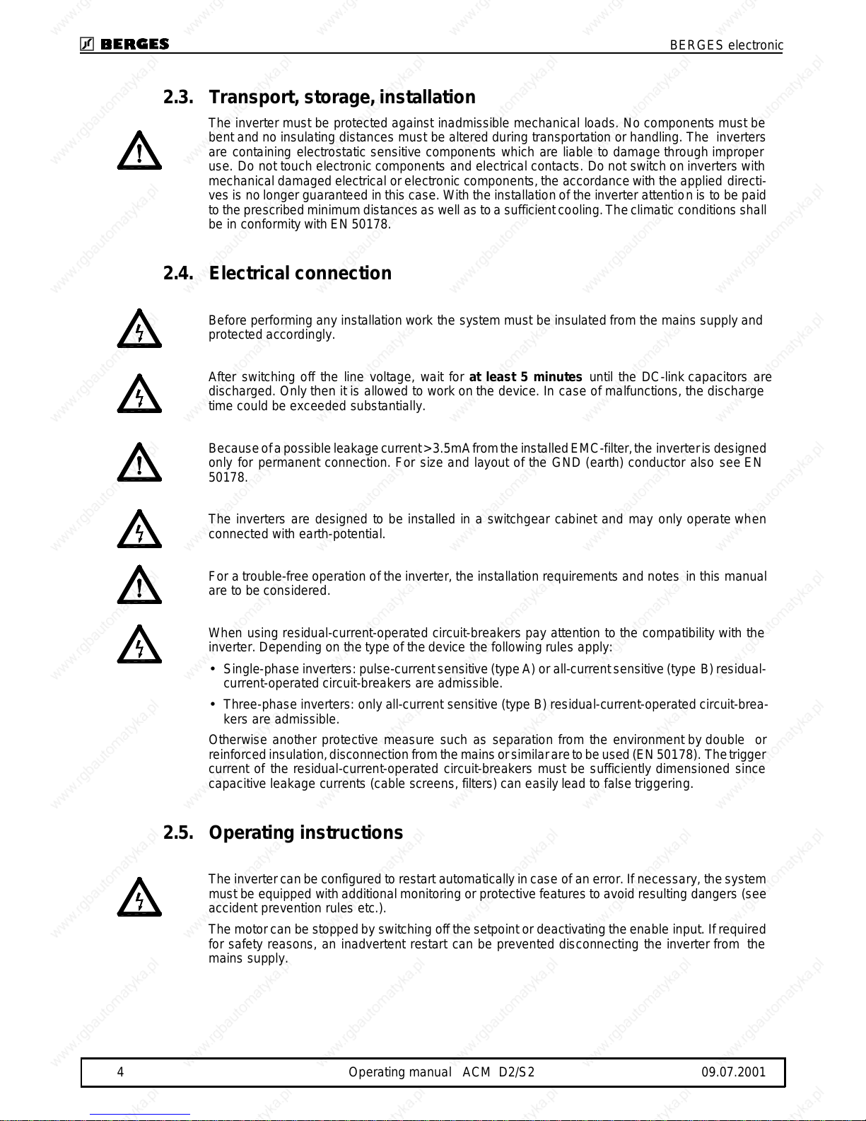
2.3.Transport, storage, installation
The inverter must be protected against inadmissible mechanical loads. No components must be
bent and no insulating distances must be altered during transportation or handling. The inverters
are containing electrostatic sensitive components which are liable to damage through improper
use. Do not touch electronic components an d electrical contacts. Do not switch on inverters with
mechanical damaged electrical or electronic components, the accordance with the applied directi-
ves is no longer guaranteed in this case. With the installation of the inverter attention is to be paid
to the prescribed minimum distances as well as to a sufficient cooling. The climatic conditions shall
be in conformity with E N 50178.
2.4.Electrical connection
Before performing any installation work the system must be insulated from the mains supply and
protected accordingly.
After switching off the line voltage, wait for at least 5 minutes un til the DC-link capacitors are
discharged. Only then it is allowed to work on the device. In case of malfunctions, the discharge
time could be exceeded substantially.
Because of a possible leakage current > 3.5mA from the installed EMC-filter, the inverter is designed
only for permanent connection. For size and layout of the GND (earth) conduc tor also see EN
50178.
The inverters are designed to be installed in a switchgear cabinet and may only operate when
connected with earth-potential.
For a trouble-free operation of the inverter, the installation requirements and notes in this manual
are to be considered.
When using residual-current-operated circ uit-breakers pay attention to the compatibility with the
inverter. Depending on the type of the device the foll owing rules apply:
•Single-phase inverters: pulse-current sensitive (type A) or all-current sensitive (type B) residual-
current-operated circuit-breakers are admissible.
•Three-phase inverters: only all-current sensitive (type B) residual-current-operated circuit-brea-
kers are admissible.
Otherwise another protective measure such as separation from the environment by double or
reinforced insulation, disconnection from the mains or similar are to be used (EN 50178). The trigger
current of the residual-current-operated circuit-bre akers must be sufficiently dimensioned since
capacitive leakage currents (cable screens, filters) can e asily lead to false triggering.
2.5.Operating instructions
The inverter can be configured to restart automatically in case of an error. If necessary, the system
must be equipped with additional monitoring or protective features to avoid resulting dangers (see
accident prevention rules etc.).
The motor can be stopped by switching off the setpoint or deactivating the enable input. If required
for safety reasons, an inadvertent restart can be preven ted disconnecting the inverter from the
mains supply.
BERGES electronic
4 Operating manual ACM D2/S2 09.07.2001
2.6. Miscellaneous
We point out that we do not take the re sp onsibility for da ma ge and operation al disturbances resulting
from the neglect of this oper ating manual.
Technical changes may be carried out to improve the device and its functions.
Before you continue reading, please check whether technical amendments are attached
in the annex to this operating manual!
BERGES electronic
09.07.2001 Operating manual ACM D2/S2 5
3.Introduction
The present operating manual contains specifications, installation instructions and troubleshooting
procedures for ACM D2/S2 inverters.
The information in this manual must be known before installation of the inverter in order to
guarantee fault-free installation and thus maximum performance.
The information contained in this manual refers to the software versions
D2A-STD-020A
and
D2A-1300-021.
BERGES electronic
6 Operating manual ACM D2/S2 09.07.2001
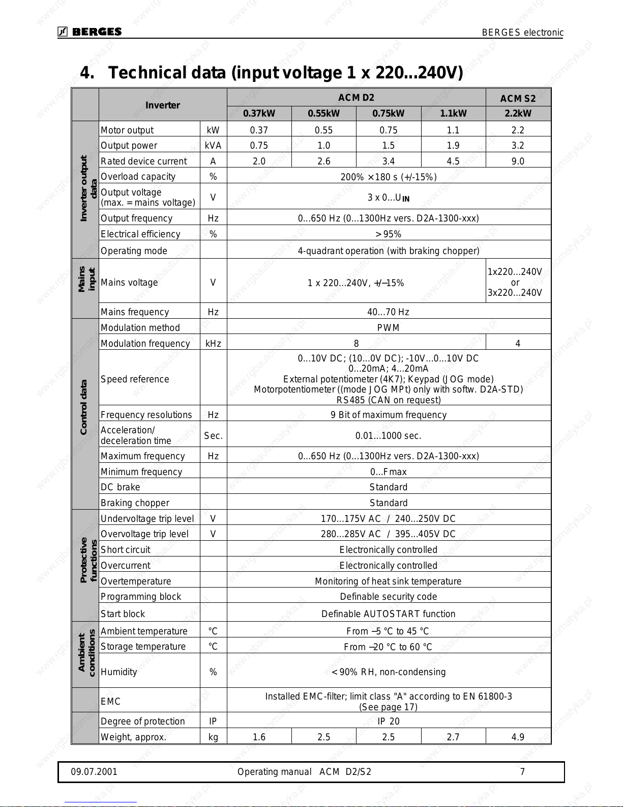
4. Technical data (input voltage 1 x 220...240V)
Inverter
ACM D2
ACM S2
0.37kW 0.55kW 0.75kW 1.1kW 2.2kW
Motor output kW 0.37 0.55 0.75 1.1 2.2
Output power kVA 0.75 1.0 1.5 1.9 3.2
Rated device current A 2.0 2.6 3.4 4.5 9.0
Overload capacity %
200% × 180 s (+/-15%)
Output voltage
(max. = main s voltage)
V3 x 0...U
IN
Output frequency Hz 0...650 Hz (0...13 00 Hz vers. D2 A-1 30 0-xxx)
Electrical efficiency % > 95%
Operating mode 4-quadrant operation (with braking chopper)
Mains voltage V
1 x 220...240V, +/−15%
1x220...240V
or
3x220...240V
Mains frequency Hz 40...70 Hz
Modula ti on method PWM
Modulation frequency kHz 8 4
Speed re fe re nce
0... 10V DC; (10.. . 0V DC); -1 0V...0...10V DC
0...20mA; 4...20mA
External potentiometer (4 K7); Ke ypad (J O G mode)
Motorpo te n t i om eter ((mode JOG MPt) only with softw. D2A-STD)
RS485 (CAN on request)
Frequency resolutions Hz 9 Bit of maximum frequency
Acceleration/
deceleration time
Sec. 0.01...1000 sec.
Maximum freque ncy Hz 0 ...65 0 Hz (0...13 00 Hz ve rs. D2A-1 30 0-xxx)
Minimum frequency 0...Fmax
DC brake Standard
Braking chopper Standard
Undervoltage trip level V 170...175V AC / 240...250V DC
Overvoltage trip level V 280...285V AC / 395...405V DC
Short circuit Electronically controlled
Overcurrent Electronically controlled
Overtempera ture Monitoring of heat sink tem pe rature
Programming block Definable security code
Start block
Definable AUTOSTART function
Ambient temperature °C
From −5 °C to 45 °C
Storage temperature °C
From −20 °C to 60 °C
Humidity % < 90% RH, non-condensing
EMC
Installed EMC-filter; limit class "A" according to EN 61800-3
(See page 17)
Degree of protection IP IP 20
Weight , approx. kg 1.6 2.5 2.5 2.7 4.9
Inverter output
data
Mains
input
Control dataProtective
functions
Ambient
conditions
BERGES electronic
09.07.2001 Operating manual ACM D2/S2 7
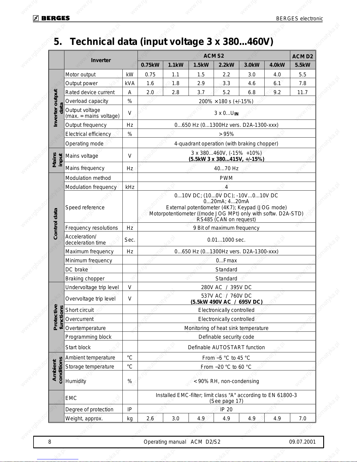
5. Technical data (input voltage 3 x 380...460V)
Inverter
ACM S2
ACM D2
0.75kW 1.1kW 1.5kW 2.2kW 3.0kW 4.0kW 5.5kW
Motor output kW 0.75 1.1 1.5 2.2 3.0 4.0 5.5
Output power kVA 1.6 1.8 2.9 3.3 4.6 6.1 7.8
Rated de vic e cu rre nt A 2.0 2.8 3.7 5.2 6.8 9.2 11.7
Overload capacity %
200% × 180 s (+/-15%)
Output voltag e
(max. = mains voltage)
V3 x 0...U
IN
Output frequency Hz 0...650 Hz (0...1300Hz vers. D2A-1300-xxx)
Electrical efficiency % > 95%
Operatin g mode 4-quadra nt ope ration (wi th brak i ng chopper)
Mains voltage V
3 x 380...460V, (-15% +10%)
(5.5kW 3 x 380...4 15V , +/-15%)
Mains freq uency
Hz 40...70 Hz
Modulation method PWM
Modulation frequency kHz 4
Speed reference
0...10V DC; (1 0. ..0V DC); -10V...0.. .10V DC
0...20mA; 4...20mA
External potentiometer (4K7); Keypad (JOG mode)
Motorpotentiometer ((mode JOG MPt) only with softw. D2A-STD)
RS485 (C A N on request)
Frequency resolutions Hz 9 Bit of maximum frequency
Acceleration/
deceleration time
Sec. 0.01...1000 sec.
Maximum frequency Hz 0...650 Hz (0...1300Hz v ers. D2A-1300-xxx)
Minimum frequency 0...Fmax
DC brake Standard
Braking chopper Standard
Undervoltage trip level V 280V AC / 395V DC
Overvoltage trip level V
537V AC / 760V DC
(5.5kW 490V AC / 695V DC)
Short circuit Electronically co ntrolled
Overcurrent Electronically controlled
Overtemperature Monitoring of heat sink temperature
Programming block Definable security code
Start block Definable AUTOSTART function
Ambient temperature °C
From −5 °C to 45 °C
Storage temperature °C
From −20 °C to 60 °C
Humidity % < 90% RH, n on-condensing
EMC
Installed EMC-filter; limit class "A" according to EN 61800-3
(See page 17 )
Degree of protection IP IP 20
Weight, ap prox. kg 2.6 3.0 4.9 4.9 4.9 4.9 7.0
Inverter output
data
Mains
input
Control dataProtective
functions
Ambient
conditions
BERGES electronic
8 Operating manual ACM D2/S2 09.07.2001
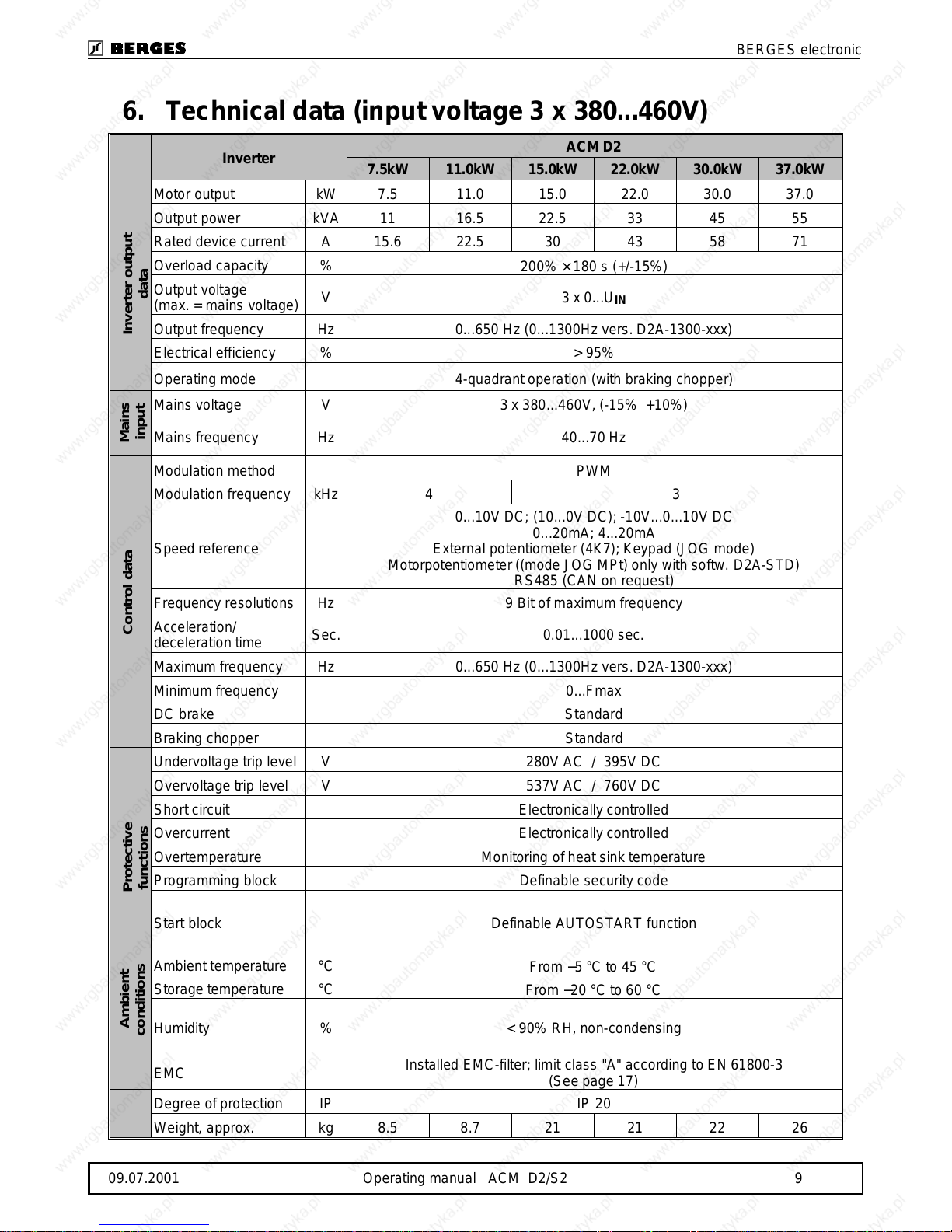
6. Technical data (input voltage 3 x 380...460V)
Inverter
ACM D2
7.5kW 11.0kW 15.0kW 22.0kW 30.0kW 37.0kW
Motor output kW 7.5 11.0 15.0 22.0 30.0 37.0
Output power kVA 11 16.5 22 .5 33 45 55
Rated device current A 15.6 22.5 30 43 58 71
Overload capacity %
200% × 180 s (+/-15%)
Output voltage
(max. = main s voltage)
V3 x 0...U
IN
Output frequency Hz 0...650 Hz (0...13 00 Hz vers. D2 A-1 30 0-xxx)
Electrical efficiency % > 95%
Operating mode 4-quadrant operation (with braking chopper)
Mains volta ge V 3 x 380...460V, (-15% +10%)
Mains frequency Hz 40...70 Hz
Modula ti on method PWM
Modulation frequency kHz 4 3
Speed re fe re nce
0... 10V DC; (10.. . 0V DC); -1 0V...0...10V DC
0...20mA; 4...20mA
External potentiometer (4 K7); Ke ypad (J O G mode)
Motorpo te n t i om eter ((mode JOG MPt) only with softw. D2A-STD)
RS485 (CAN on request)
Frequency resolutions Hz 9 Bit of maximum frequency
Acceleration/
deceleration time
Sec. 0.01...1000 sec.
Maximum freque ncy Hz 0 ...65 0 Hz (0...13 00 Hz ve rs. D2A-1 30 0-xxx)
Minimum frequency 0...Fmax
DC brake Standard
Braking chopper Standard
Undervoltage trip level V 280V AC / 395V DC
Overvoltage trip level V 537V AC / 760V DC
Short circuit Electronically controlled
Overcurrent Electronically controlled
Overtempera ture Monitoring of heat sink tem pe rature
Programming block Definable security code
Start block Definable AUTOSTART function
Ambient temperature °C
From −5 °C to 45 °C
Storage temperature °C
From −20 °C to 60 °C
Humidity % < 90% RH, non-condensing
EMC
Installed EMC-filter; limit class "A" according to EN 61800-3
(See page 17)
Degree of protection IP IP 20
Weight, approx. kg 8.5 8.7 21 21 22 26
Inverter output
data
Mains
input
Control dataProtective
functions
Ambient
conditions
BERGES electronic
09.07.2001 Operating manual ACM D2/S2 9

7.Power-derating in function of the switching
frequency
P
N
Nominal power
P
OUT
Output power
f
PWM
Switching frequency
Ambient conditions: T
amb
= 45°C
0,0
0,2
0,4
0,6
0,8
1,0
0481216
f
(kHz)
P
out
/ P
N
ACM D2/S2 0,37-2,2kW/230V
ACM S2 0,75-4,0kW/400V
ACM D2 5,5kW/400V
ACM D2 7,5kW/400V
ACM D2 11kW/400V
ACM D2 22-37kW/400V
ACM D2 15kW/400V
N
/ P
out
P
(kHz)
PWM
f
1230
1,2
1,0
0,8
0,6
0,4
0,2
0,0
6
BERGES electronic
10 Operating manual ACM D2/S2 09.07.2001

8.Dimensional data ACM D2/S2 0.37 kW - 5.5 kW
Additional mounting bracke t:
only for ACM D2 5.5kW
Dimensions (in mm)
ACM 1x230V ACM 3x400V
D2 S2 S2 D2
0,370,550,751,11,52,20,751,11,52,23,04,05,5
A
154153153153194194194194194194194194265
B
168168168168208208208208208208208208280
C
181181181181222222222222222222222222293
D
5353 53 585454 54 545454545458
E
108106106106109109109109109109109109116
F
-404045676767676767676790
G
- 146146151176176176176176176176176206
H
Ø6Ø6Ø6Ø6Ø6Ø6Ø6Ø6Ø6Ø6Ø6Ø6Ø6
I
180180180180174174174174174174174174180
J
190190190190179179179179179179179179200
K
1414 14 141414 14 141414141414
L
------------35
ACM D2 0.37 - 1.1kW
C B
A
F
G
L
E
D
H
H
ACM D2/S2 0.75 - 5.5kW
BERGES electronic
09.07.2001 Operating manual ACM D2/S2 11

9.Dimensional data ACM D2 7.5 kW - 22.0 kW
Dimensions (in mm)
ACM D2 (3x400V)
7.5 11.0 15.0 22.0
A
317 317 330 330
B
344 344 375 375
C
367 367 390 390
D
54.25 54.25 48 48
G
209 209 250 250
H
Ø7 Ø7 Ø6 Ø6
I
186 186 310 310
J
198 198 325 325
K
25 25 30 30
L
154.75 154.75 205 205
ACM D2 7.5 - 11.0kW ACM D2 15.0 - 22.0kW
BERGES electronic
12 Operating manual ACM D2/S2 09.07.2001

10. Dimensional data ACM D2 30.0 kW - 37.0 kW
Dimension s (in mm)
ACM D2 (3x400V)
30.0 37.0
A
442 442
B
343 408
C
422 422
D
242 242
E
35.5 67
F
65.5 98.5
G
Ø7 Ø7
H
255 255
ACM D2 30. 0 - 37.0kW
ACM D2 30.0 - 37.0kW
BERGES electronic
09.07.2001 Operating manual ACM D2/S2 13

11.Installation examples
11.1.Example 1: ACM D2/S2 0.37 kW - 2.2 kW (1 x 230V)
1)The GND terminals (10, 12 and 14) are floating and serve, among other things, as the
reference potential for shielded cables of the control inputs. This potential must be grounded
directly either at the control side (PLC or similar) or at the inverter (PE to one of the terminals
10, 12 or 14).
2)The option “Output chokes” is suitable for reducing the capacitive currents to ground and also
the interference originating from the inverter.
3)Option relay board “REL”, see functions OC1/OC2 page 48/49.
4)Option ACM - Synchronizer. (Only with Software D2A-STD).
5)Speed reference with motorpotentiometer possible only with Software D2A-STD.
The terminal assignment shown in this drawing refers to the setting “Active LOW”.
BERGES electronic
14 Operating manual ACM D2/S2 09.07.2001

11.2.Example 2: ACM D2/S2 0.75 kW - 37.0 kW (3 x 400V)
1)The GND terminals (10, 12 and 14) are floating and serve, among other things, as the
reference potential for shielded cables of the control inputs. This potential must be grounded
directly either at the control side (PLC or similar) or at the inverter (PE to one of the terminals
10, 12 or 14).
2)The option “Output chokes” is suitable for reducing the capacitive currents to ground and also
the interference origin atin g from the inverter.
3)Option relay board “REL”, see functions OC1/OC2 page 48/49.
4)Option ACM - Synchronizer. (Only with Software D2A-STD).
5)Speed reference with motorpotentiometer possible only with Software D2A-STD.
6)
Inputs non-insulated.
The terminal assignment shown in this drawing refers to the setting “Active LOW”.
BERGES electronic
09.07.2001 Operating manual ACM D2/S2 15
12.Installation
12.1.Installation
The frequency inverters are designed for installation in a switchgear cabinet and for
permanent connection.
The inverter must be installed so that the heat sink is facing to the right. Only in this way sufficient
cooling is guaranteed.
If the inverter has to be installed in a different position, external coolin g is required for full capacity
utilization.
BERGES inverters are generally designed so that they can be operated at ambient temperatures
from −5 °C to +45 °C and at a relative humidity of up to 90%.
Formation of condensation must be avoided!
Please contact BERGES if the above values are exceeded. A heat build-up at the inverter during
operation must be prevented. The internal air circulation may possibly be in sufficient if the unit is
installed in a control cabinet with a small volume.
The units should never be installed in the proximity of corrosive or flammable gases, conductive
dust or large magnetic and electric fields.
The inverter should be installed in a location that is largely free of dust, steam and vibrations.
Operation of the units in the presence of abrasive dust, steam, condensate, oil mist or air containing
salt will reduce their useful life.
Pay close attention during installation to ensuring that no objects (such as drilling swarf, wire or
anything else) fall into the unit. Otherwise a device fault cannot be excluded, even after longer
periods of operation.
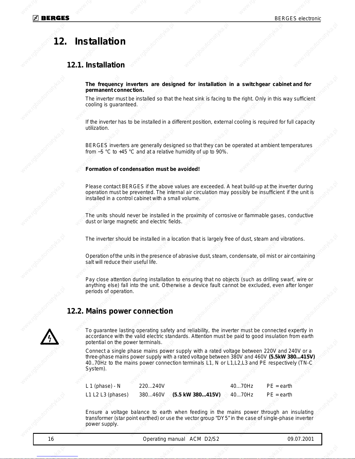
12.2.Mains power connection
To guarantee lasting operating safety and reliability, the inverter must be connected expertly in
accordance with the valid electric standards. Attention must be paid to good insulation from earth
potential on the power terminals.
Connect a single phase mains power supply with a rated voltage between 220V and 240V or a
three-phase mains power supply with a rated voltage between 380V and 460V
(5.5kW 380...415V)
40..70Hz to the mains power connection terminals L1, N or L1,L2,L3 and PE respectively (TN-C
System).
L 1 (phase) - N 220...240V 40...70Hz PE = earth
L1 L2 L3 (phases) 380...460V
(5.5 kW 380...415V)
40...70Hz PE = earth
Ensure a voltage balance to earth when feeding in the mains power through an insulating
transformer (star point earthed) or use the vector group “DY5” in the case of single- phase inverter
power supply.
BERGES electronic
16 Operating manual ACM D2/S2 09.07.2001

12.3.Motor connection
Connect the motor cable to the
U, V, W
and PE terminals.
The inverter will be deactivated in the event of a short circuit at the terminals
U, V, W.
We recommend PTC evaluation using commercially available devices to achieve effective protection
of the motor.
If interrupting contacts (e.g. contactors or motor protection switches etc.) have to be installed between
the motor and inverter, the circuit must be configured so as to ensure that the
ENABLE
signal (terminals
10/11) is deactivated
before
separation of the inverter/motor connection. A relay switching time of
approx. 30 ms suffices.
Long motor cables (> 20m) in connection with high voltage peaks caused by the fast switching output
stages of the inverter may endanger the motor insulation. In such cases we recommend to use suitable
filter measures (e.g. motor chokes or dU/dt filters) to protect the motor.
12.4.Interference supp ression measures / EMC
(electromagnetic compatibility)
12.4.1.General information
Inverters are electronic devices which are used in industrial and commercial sys tems. In accordance
with the EMC-directives 89/336/EEC the inverters are not designed for independ en t operation. Thus
inverters should be used for further processing thro ugh competent machine/system manufacturers.
By this, the devices do not require a CE-marking. The proof of the conformity of the machine/system
with the required EMC-directives must be furnished by the manufacturer or operator of the system.
The inverters of the ACM series are equipped with an internal filter and designed to be used in class
"A" environments (first environment, restricted distribution) according to the product standard EN
61800-3.
The evaluation of the conformity took place in a practical structure having taken into account the
following installation notes.
Voltage peaks produced by other devices connected at the mains supply can possibly disturb or even
damage the inverter. Input ch ok es (option) can be used to protect the inverter against these voltage
peaks (caused e.g. by switching off of high loads from the mains).
12.4.2.Installation notes
During operation, electrical/electronic devices can influence or disturb each other via power supply or
other metallic connections.
The electromagnetic compatibility of the system is highly influenced by the manner of the installation.
Measures for the grounding, shielding and filtering are to be particularly considered. By paying attention
to the following installation notes it can be assumed that the EMC limit values for the system/machine
are kept.
•Inverters and optional components like input or output chokes must be in metal-to-metal contact
with the grounded mounting plate using the whole surface if possible. Use prefera bly galvanized
mounting plates. Painted mounting surfaces must be free from paint.
•Lay the mains, motor and control cables in large distance from each other.
•Use shielded motor cables connected to earth on both sides.
•Connect the motor cable shield with the PE terminal located in the terminal box of the motor. Use
possibly metallic cable glands.
•Optional output chokes must be mounted close to the inverter and connected with shielded cables.
Connect the cable shield to earth on both sides.
•Use shielded control cables connected to earth on both sides.
•Unshielded control cables must be twisted.
•Connect the cable shields either with the mounting plate using ground clamps and contacted over
as large an area or at an equipotential bar (see picture).
•Use a central earthing point for the whole machine/syste m (mounting plate). Connect this point to
earth using earth cables with a large cross section or fl at copper braids.
Remove any
paint or varnish!
Motor cable with
braided shield.
Large-area contacting
of the cable shield.
BERGES electronic
09.07.2001 Operating manual ACM D2/S2 17
•Do not extend the shields with single wires and do not interrupt them if possible.
•When constructing the switchgear cabinet or the system, separate the power section from the
control section. Eventually provide a shield between power and control section.
•Wire inductive switching elements (coils of contactors or relays) with RC-elements, free-wheeling
diodes or varistors.
12.5.Mains back-up fuses
External upstream fuses are required to protect the cables and the unit i tself. The fuses must be
dimensioned so as to permit starting u p and normal operation of motors. To guarantee this, we
recommend the use of the followings slow-blow fuses:
Mains input 1 x 230V
0.37kW 0.55kW 0.75kW 1.1kW 2.2kW
4A 8A 8A 8A 16A
Mains input 3 x 400V
0.75kW 1.1kW 1.5kW 2.2kW 3.0kW 4.0kW 5.5kW
4A 6A 6A 8A 10A 16A 20A
Mains input 3 x 400V
7.5kW 11.0kW 15.0kW 22.0kW 30.0kW 37.0kW
35A 35A 63A 63A 80A 100A
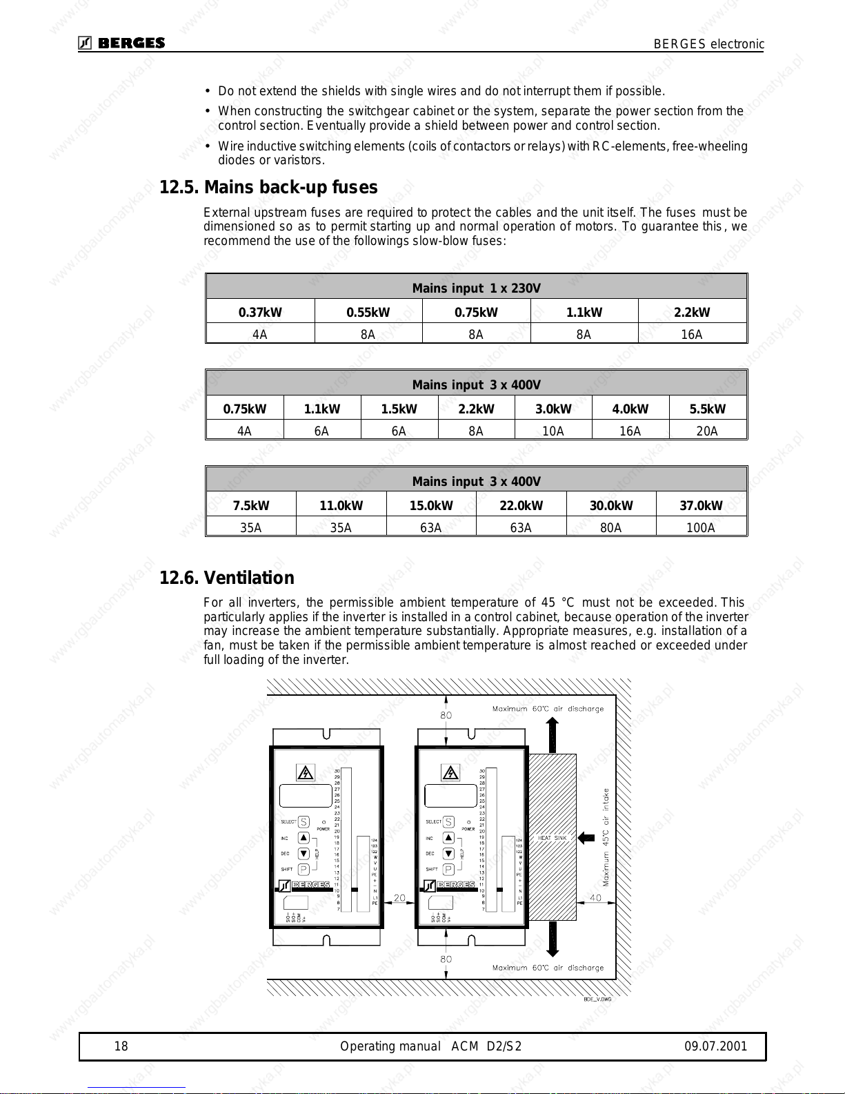
12.6.Ventilation
For all inverters, the permissible ambient temperature of 45 °C must not be exceeded. This
particularly applies if the inverter is installed in a control cabinet, because operation of the inverter
may increase the ambient temperature substantially. Appropriate measures, e.g. installation of a
fan, must be taken if the permissible ambient temperature is almost reached or exceeded under
full loading of the inverter.
BERGES electronic
18 Operating manual ACM D2/S2 09.07.2001
 Loading...