

Page 1
Applicable Country & Regions:
t
Ta iw an
Product Service Manual – Level 2
Service Manual for BenQ:
Monitor-TV /MK2432
<9H.V0H75.JCT>
Version: 00a
Date: 2009/08/31
Notice:
For RO to input specific “Legal Requirement” in specific NS regarding to responsibility and liability
statements.
Please check BenQ’s eSupport web site, http://esupport.benq.com, to ensure that you have the mos
recent version of this manual.
First Edition (August 2009)
© Copyright BenQ Corporation 2007. All Right Reserved.
1
Page 2

Content Index
ABBREVIATIONS & ACRONYMS ......................................................................................................... 2
ABOUT THIS MANUAL ......................................................................................................................... 4
INTRODUCTION ................................................................................................................................... 4
GENERAL DESCRIPTIONS.................................................................................................................... 5
RELATED SERVICE INFORMATION .................................................................................................... 5
PRODUCT OVERVIEW .......................................................................................................................... 5
SPECIFICATION ................................................................................................................ 6
PACKING .......................................................................................................................... 26
CUSTOMER ACCEPTANCE ............................................................................................ 28
LEVEL 1 COSMETIC / APPEARANCE / ALIGNMENT SERVICE ..................................................... 31
VISUAL INSPECTION & CLEANING ............................................................................. 31
SOFTWARE / FIRMWARE UPGRADE PROCESS ........................................................... 39
ADJUSTMENT / ALIGNMENT PROCEDURE ............................................................... 46
LEVEL 2 CIRCUIT BOARD AND STANDARD RARTS REPLACEMENT ......................................... 49
EXPLODED VIEW ............................................................................................................ 49
DISASSEMBLY / ASSEMBLY ............................................................................................ 51
SYSTEM
TROUBLE SHOOTING .................................................................................................... 58
APPENDIX 1- SCREW LIST/TORQUE ................................................................................................ 60
APPENDIX 2 – IR CODE ...................................................................................................................... 61
APPENDIX 3- WALL MOUNT ............................................................................................................. 62
BLOCK DIAGRAM ............................................................................................ 57
Abbreviations & Acronyms
2
Page 3
A
A
A/D Converter
B
BenQ BenQ Corporation
C
D
DTV Digital Television
E
EMI Electromagnetic Interference
F
G
H
HDMI High Definition Multimedia Interface
I
J
K
L
M
N
nalog to Digital Converter
NTSC National Television System Committee
O
OSD On Screen Display
P
PAL Phase Alternating Line
Q
R
RS232 Interface Between Data Terminal Equipment and Data
Communications Equipment Employing Serial Binary
Data Interchange
S
T
U
V
About This Manual
3
Page 4

This manual contains information about maintenance and service of BenQ products. Use this
manual to perform diagnostics tests, troubleshoot problems, and align the BenQ product.
Important
Only trained service personnel who are familiar with this BenQ Product shall
perform service or maintenance to it. Before performing any maintenance or service,
the engineer MUST read the “Important Safety Information”.
Tr a demar k
The following terms are trademarks of BenQ Corporation:
BenQ
Senseye
Other companies, products, or service names may be the trademarks of their respective companies.
Introduction
This section contains general service information, please read through carefully. It should be stored
for easy access place.
Important Service Information
RoHS (2002/95/EC) Requirements – Applied to all countries require RoHS.
The RoHS (Restriction of Hazardous Substance in Electrical and Electronic Equipment Directive) is
a legal requirement by EU (European Union) for the global electronics industry which sold in EU
and some counties also require this requirement.Any electrical and electronics products launched in
the market after June 2006 should meet this RoHS requirements.Products launched in the market
before June 2006 are not required to compliant with RoHS parts.If the original parts are not RoHS
complaints, the replacement parts can be non ROHS complaints,but if the original parts are RoHS
compliant, the replacement parts MUST be RoHS complaints. If the product service or maintenance
require replacing any parts, please confirming the RoHS requirement before replace them.
Safety Notice
4
Page 5

1. Make sure your working environment is dry and clean, and meets all government safety
requirements.
2. Ensure that other persons are safe while you are servicing the product.
3. DO NOT perform any action that may cause a hazard to the customer or make the product
unsafe.
4. Use proper safety devices to ensure your personal safety.
5. Always use approved tools and test equipment for servicing.
6. Never assume the product’s power is disconnected from the mains power supply. Check that it
is disconnected before opening the product’s cabinet.
7. Modules containing electrical components are sensitive to electrostatic discharge (ESD). Follow
ESD safety procedures while handling these parts.
8. Some products contain more than one battery. Do not disassemble any battery, or expose it to
high temperatures such as throwing into fire, or it may explode.
9. Refer to government requirements for battery recycling or disposal.
Compliance Statement
Caution: This Optical Storage Product contains a Laser device. Refer to the product specifications
and your local Laser Safety Compliance Requirements.
General Descriptions
This Service Manual contains general information. There are 2 levels of service:
Level 1: Cosmetic / Appearance / Alignment Service
Level 2: Circuit Board or Standard Parts Replacement
Related Service Information
Service Web Site
BenQ Global Service Website: http://www.benq.com/support/
eSupport Website: http://esupport.benq.com/v2
Product Overview
This specification describes a display device that is based on a 23.6 inch TFT LCD display
5
Page 6

TV/Monitor. The part number of the panel is CMO M236H1-L01. The native resolution of the
panel is 1920 X 1080. At this resolution the monitor device can be described as WUXGA and the
television can be best described as “HDTV” or Extended Definition Television. This
television/monitor can be used to display high definition television images as images that are scaled
to the native resolution of 1920 X 1080. The television/monitor is also provided with a television
tuner as an integral part of the systems. This provision allows the monitor to function directly as a
television. It is capable of receiving off-the-air, cable, and satellite transmissions. The monitor inputs
that are provided have the ability to adapt this device to practically any consumer video source
output that is available in the marketplace. It features S-video, composite video, and component
video. The monitor computer inputs are VGA analog and HDMI(PC and HDCP). This
television/monitor provides maximum flexibility in the number of applications that it can provide
to the end user.
Specification
(1). Panel:
- Center luminance 300nits (Typical) ,250nits (Min)
- Contrast ratio approximates 1000:1 (Typical) 700:1(Min)
- Viewing angle (Horizontal and vertical) 170 (H) / 160 (V) (Typ.)
- Resolution: 1920 x 1080, 16:9
(2). PC:
- Analog PC support timing up to 1920*1080 60Hz 138.5MHz
- High quality scaling function
- With power saving function (PC mode)
- PC Audio input
(3). Video/TV:
- HDMI 1.3
- HDTV function compatible (480i, 480p, 720p, 1080i, 1080p)
- Built-in De-Interlace, Noise Reduction, 3:2 pull down function
(4). Tuner: (SECAM D/K, PAL B/G, I).
CVBS, AV Audio, S-Video, Component( YCrCb / YPrPb )
-
Sound : Mono/Stereo/SAP
-
(5). Audio:
- Built-in 5W x2 for 23.6”.
- Earphone output
- Audio fixed output
(6). Power:
-110 Vac ~ 240 Vac universal power
(7). User interface:
- User controls: on/off switch, key pad with input select, menu, channel up, channel down, left( - ),
6
Page 7
right ( + )
- IR remote controller
- Fancy OSD (on screen display) for user control interface
- Color indicator for power on/standby
(8). It is composed of the following material and accessories (Accessory might be adjusted by
different territory request):
-LCD TV *1
-User Manual + warranty card
-A power cord
-Remote control x 1 & AAA batteries x 2
-A VGA cable
Operational Specification
(1) Environment
Temperature:
-The operating temperature range shall be 0oC to 40oC.
-The non-operating temperature range shall be –20oC to 60oC.
Humidity:
-Operating 10% to 65% non-condensing
-Non-operating 0% to 90% non-condensing
(2) Physical Specifications
Product characteristics:
Net Weight (Kg) Gross Weight (Kg)
Dimension w/o Base
W*H*D (mm)
6.8Kg 8.7Kg 566.7*387.4*84.4
Package dimension:
Carton Interior Dimension (mm)
Carton External Dimension (mm)
W*H*D
610*483*135 620*508*145
Dimension w/ Base
W*H*D (mm)
566.7*442.7*216
W*H*D
Assembly Specification:
Gap LCD Panel/bezel
ITEMS
Specification
1.2mm
7
Page 8
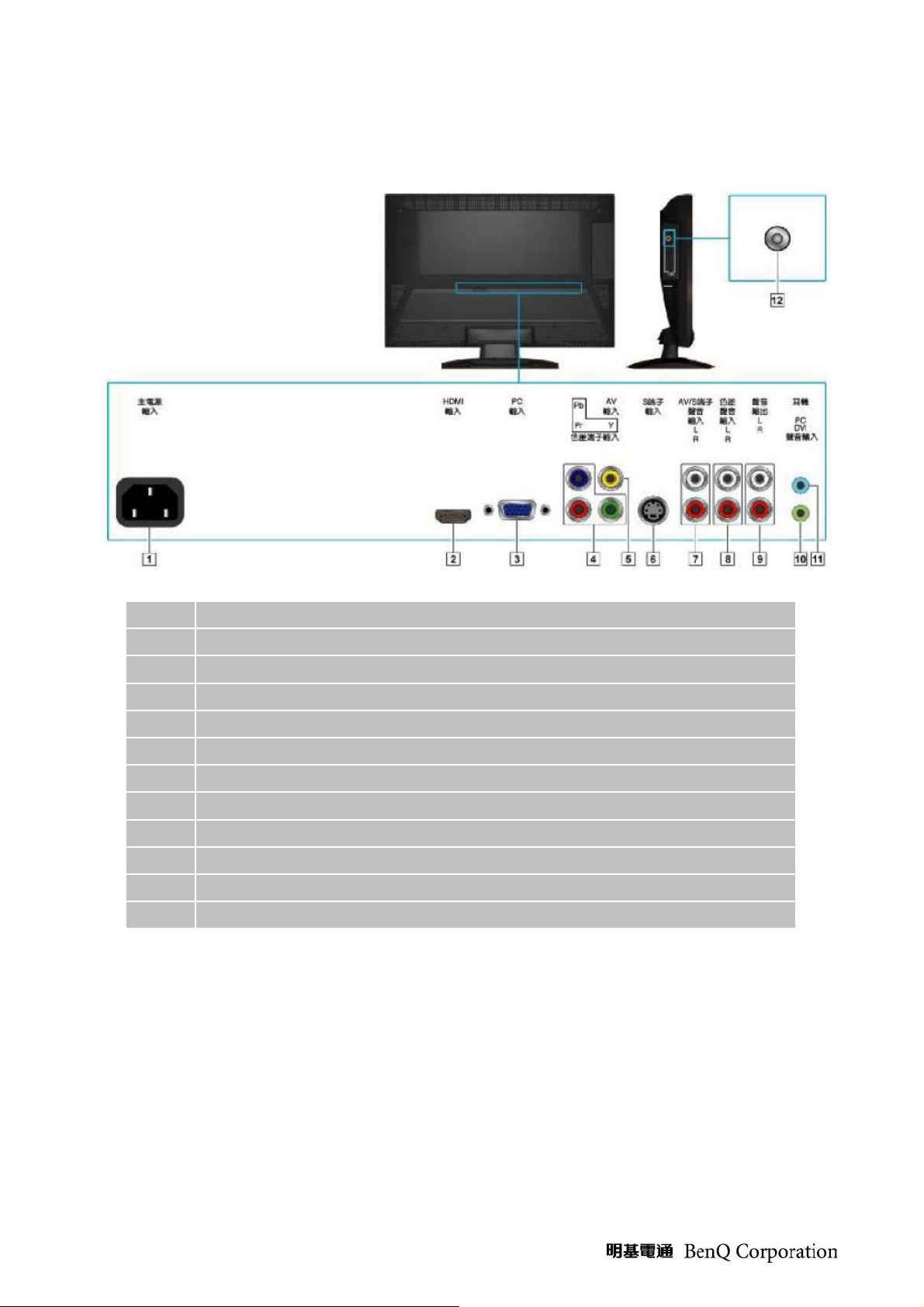
(3) Input / Output Signal Specification
1 AC inlet (AC Power input)
2 HDMI input (DVI 1.0 specification compatible)
3 VGA (D-Sub-15 pin) Input
4 Component Video (YPbPr) input
5 Composite Video (CVBS) input
6 S-Video input
7 AV/ S-Video Shared audio input (RCA L / R)
8 Component Video (YPbPr) audio input (RCA L / R)
9 Fixed Audio Out (RCA L / R)
10 PC Audio input for VGA / DVI
11 Headphone Jack
12 Terrestrial Analog TV (NTSC-M) input
8
Page 9
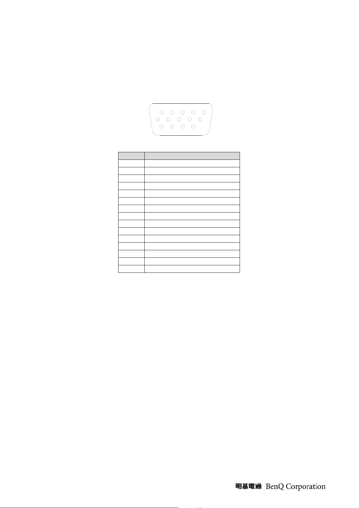
1. PC Analog Signal
V-sync
Signal cable :
D-Sub: 15pin D-sub connector is on the captive signal cable for IBM VGA or compatible graphic
adapters. The shall be 1.8 meters long.The pin assignment of this connector is described as below:
1
6
11
5
10
15
Pin D-Sub Connector
1 Red
2 Green
3 Blue
4 RX
5 GND
6 Red GND
7 Green GND
8 Blue GND
9 +5V for DDC
10 GND
11 TX
12 SDA
13 H-sync
14
15 SCL
Signal Level:
RGB separate, Analog 0.7Vp-p/75 Ohm
Input signal Quality:
(1) Rise/Fall time
-Video Signal: less than 4.0ns
(2) TTL Signal Level
The levels of Horizontal & Vertical Sync will be TTL levels, their high level will be 2.4-5.5V, and low
level will be 0-0.2V.
(3) Video Signal Level
The video signal when terminated with an idea 75 ohm termination will have a range of 0V to 0.7V
(normal), and its full scale output will be 0.7V and black level will be between 0V and 0.1V.
9
Page 10
Signal Timing:
Mode
IBM, VGA 720x400@70Hz
VGA
SVGA
XGA
XGA+ 1152x864@75Hz
WXGA+ 1280x960@60Hz
SXGA
WXGA 1360x768@60Hz
WXGA+ 1440x900@60Hz
WSXGA+ 1680x1050@60Hz
WUXGA 1920x1080@60Hz(R)
WUXGA 1920x1080@60Hz
MAC 640x480@67Hz
MAC 832x624@75Hz
MAC 1152x870@75Hz
Resolution
Plus
Frequency
640x480@60 Hz
640x480@72 Hz
Horizontal
Frequency
(kHz)
31.469
31.469
37.861
Vertical
Frequency
(Hz)
Pixel
Frequency
(MHz)
70.080 28.320
59.940 25.175
72.809 31.500
640x480@75 Hz 37.500 75.000 31.500
800x600@56Hz 35.156 56.250 36.000
800x600@60Hz
800x600@72Hz
800x600@75Hz
37.879
48.077
46.875
60.317 40.000
72.188 50.000
75.000 49.500
1024x768@60Hz 48.363 60.004 65.000
1024x768@70Hz
1024x768@75Hz
1280x1024@60Hz
1280x1024@75Hz
56.476
60.023
67.500
60.000
63.981
79.976
47.712
55.935
65.290
66.590
67.500
35.000
49.725
68.681
70.069 75.000
75.029 78.750
75.000 108.000
60.000 108.000
60.020 108.000
75.025 135.000
60.015 85.500
59.887 106.500
59.954 146.250
59.930 138.500
60.000 148.500
66.667 30.240
74.550 57.283
75.062 100.000
Remark: To make sure the good compatibility, the timings listed in above table is not always same as
in EDID.
2. Component Video Signal:
Connector Pin definition:
(1) Component video pin define:
A B C
(A) Cr/Pr Input
(B) Cb/Pb Input
(C) Y Input for YCrCb or YPrPb.
10
Page 11
(2) Component audio pin define:
V
A B
(A) Audio Input, right channel, for YCrCb or YprPb
(B) Audio Input, left channel, for YCrCb or YPrPb
Signal Level:
(1) YPbPr input:
Component signal: 0.7~1Vp-p/75 Ohm, negative
(2) Audio:
Level: 500 mVrms
Impedance: 600 ohms
Signal support timing:
Input from YcbCr:
Lines per frame Horizontal frequency(kHz)
525 15.734 60
625 15.625 50
625 15.625 50
525 15.734 60
ertical frequency(Hz) System
NTSC
PAL(B,G ,D,K,I)
SECAM
4.43NTSC
Input from YpbPr:
Horizontal frequency (kHz) Vertical frequency (Hz)
15.735 60
31.47 60
45.00 60
33.75 60
67.50 60
3. Audio input level
Audio monitor output Signal:
Source Input Input level ( mVrms) Audio Out
PC 500 PC
HDMI 500 (DVI)HDMI
TV 500 TV
YPbPr 500 YPbPr
AV 500 AV
SV 500 SV
Signal
SDTV 480i
SDTV 480p
HDTV 720p
HDTV 1080i
HDTV 1080p
11
Page 12
Earphone output:
a
Headphone impedance = 32 ohm
Output level 150mV
4. Output Source:
The audio from the displayed program (TV or any AVs) is permanently Left & Right outputs, for
connecting an external amplifier. The output level is either fixed or variable according to the volume
same signal as screen output.
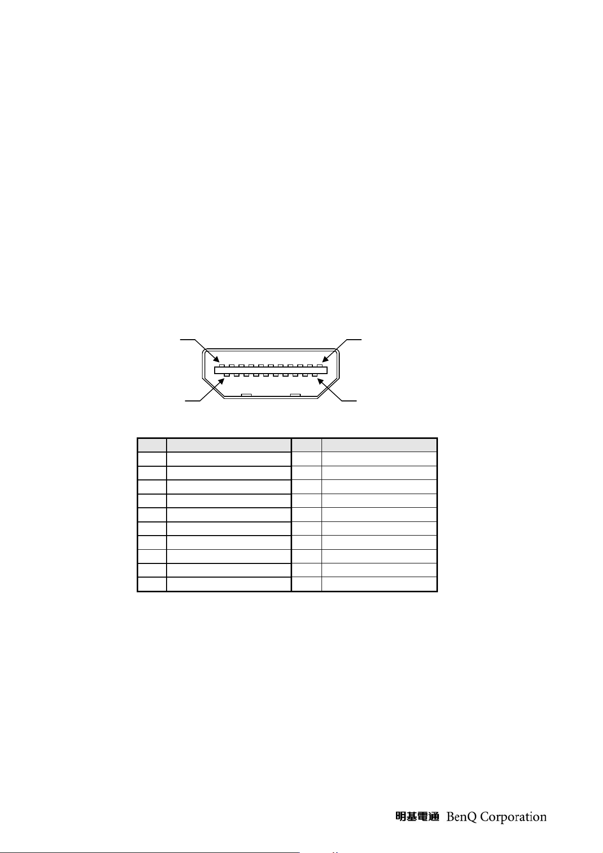
5. HDMI
Connector Pin Definition:
HDMI: 19 pins HDMI connector is designed to match with HDMI digital signal cable, the pin
assignment is as the following:
Pin 19
Pin 1
Pin 18
Pin 2
* 19 pins HDMI female
Pin Signal Assignment
Pin Signal Assignment
1 TMDS RX2+ 11 TMDS Ground
2 TMDS Ground 12 TMDS Clock3 TMDS RX2- 13 CEC
4 TMDS RX1+ 14 Floating
5 TMDS Ground 15 DDC Clock
6 TMDS RX1- 16 DDC Dat
7 TMDS RX0+ 17 Ground
8 TMDS Ground 18 +5V Power
9 TMDS RX0- 19 Hot Plug Detect
10 TMDS Clock+
12
Page 13
Signal Level:
Digital (DVI-D) applicable
HDMI / DVI Video Signal support timing:
Video signal PC signal
480i 720x400@70Hz (IBM, VGA)
480p 640x480 @ 60Hz (VESA)
720p 640x480 @ 67Hz (MAC)
1080i 640x480 @ 72Hz (VESA)
1080p 640x480 @ 75Hz (VESA)
800x600 @ 56Hz (VESA)
800x600 @ 60Hz (VESA)
800x600 @ 72Hz (VESA)
800x600 @ 75Hz (VESA)
832x624 @ 75Hz (MAC)
1024x768@60Hz (VESA)
1024x768@70Hz (VESA)
1024x768@75Hz (VESA)
1152x864@75Hz (VESA)
1152x870@75Hz (MAC)
1280x960@60Hz (VESA)
1280x1024@60Hz (VESA)
1280x1024@75Hz (VESA)
1400x1050@60Hz (VESA)
1440x900@60Hz (VESA)
1680x1050@60Hz (VESA)
1920x1080@60Hz(Reduce Blanking)
1920x1080@60Hz (VESA)
6. Power Supply Requirements
Input Power Requirements:
(1) Input Voltage Range:
Input AC Voltage range is from 100-240Vac, +/- 10% shall be available.
(2) Input Current:
Maximum Input current is 2.5A at 90Vac
(3) Frequency Range
The unit shall operate within a frequency range of 47Hz to 63Hz.
(4) Inrush Current:
80A, Power supply inrush current shall be less than the ratings of its critical components including
fuse, rectifiers and surge limiting device etc. for all conditions of line voltage.
(5) Regulator Efficiency:
80% minimum (measuring at 90Vac and full load)
(6) Normal power consumption:
Normal: 42W (Without tuner box), 48W(With tuner box),Max:60W // Stand by : <1W
13
Page 14
7. Output Functional specification
Max
-
-
Rx
Gx
Bx
ll the tests to verify specifications in this section must be performed under the following standard
A
conditions unless otherwise noted. The standard conditions are:
-Temperature: 15- 25degree Celsius
-AC line input voltage: 110~240VAC
-Checking display mode: All the presenting modes.
-Warm-up time: 30 minutes minimum
8. Display Quality
Display Performance:
Item
Parameter Specification
1 Display pixels 1920*R.G.B.*1080
2 Display cells NA
3 Pixel pitch 271.5(H)um*271.5(V) um
4 Cell pitch NA
5 Display pixel type NA
6 Active Area 521.28(H)mm*293.22(V)mm
7
Brightness
(cd/m2)
Min
Center 250
Average - -
Ty p
300
8 White variation - - 1.3
9 Contrast ratio 700 1000 -
0.617 0.647 0.677
0.304 0.334 0.364
0.254 0.284 0.314
0.577 0.607 0.637
0.121 0.151 0.181
0.041 0.071 0.101
0.283 0.313 0.343
0.299
0.329
0.359
Color
Chromaticity
Red
Green
Blue
White
Ry
Gy
By
W
x
W
y
Color Gamunt 70% 72% -
85(H)
-85(H)
80(V)
-80(V)
-
View Angle
CR=10
14
Page 15
(4) LCD Module Inspection:
15
Page 16
16
Page 17
17
Page 18
18
Page 19
3. Classification Table of defects:
V
V
V
- W
VDC
54
- -
V
- -
V
-
4. Backlight Characteristics:
Item MIN TYP MAX
Lamp Input voltage 846 940
1034
Lamp current 3 7 8
Operating frequency 40 - 80
Lamp Starting Voltage - - 1900
- - 1500
Operating life 50,000
- -
UNIT
RMS
mARMS
KHz
RMS
RMS
Hrs
Note
0°C
25°C
5. Inverter Interface Characteristics:
Item MIN
TYP
Power consumption - 26.32
Input Voltage 11.8
12.5
Oscillating frequency 48 51
Backlight Turn on Voltage
2000
1900
Input Ripple Noise - -
MAX
13.1
UNIT
KHz
RMS
RMS
mVp-p
Note
0°C
25°C
19
Page 20

(5) Audio Spec
Parameter Specification
Base band Input
Power Output Max Rating
Speaker Impedance
5W at 10% T.H.D Distortion
main spk :8 Ω
500 mV rms (Typ)
Line In
1.6 V rms (Max)
Impedance: 600 ohms
Line Out
500 mVrms +/- 10%
@1K Hz tone (with +/-25k Hz deviation at input, volume
with non-attenuation and loading with 47k Ohm)
Flatness of Amplitude Response +/- 3 db (at 1KHz @1W)
Total Harmonic Distortion
(Po=0.1 to 1 W, f=1KHz)
Signal to Noise:
<2%
40 db (50Hz to 15 KHz)
(6) Key pad control
(1) Power key: This switch is located on the Front bottom side of the display. It is a soft power
switch and not a main disconnection device. Main disconnection shall be accomplished by
physically removing the power cord from the display.
(2) Menu: Located on the top side of the display. Key shall enter, exit the OSD.
(3) CH+/CH- : Located on the top side of the display. Change Channels or navigate through OSD
depending on mode.
(4) VOL+/VOL-: Located on the top side of the display. Change Volume or navigate through OSD
depending on mode.
(5) Input:
External Connector
AC-In
RGB Input
HDMI Input
Audio Inputs X2
Audio Inputs for PC Audio
Audio Output
RF input
Composite Video
Component Video
S-Video
20
Page 21

(7) OSD Control flow
Picture
(For Video
sources)
Picture
(Only for PC
input)
Picture Mode
Picture effect selections on Dynamic (default), Standard,
Cinema, Personal
Brightness Adjust the Black levels (0~100)
Contrast Adjust the White levels (0~100)
Color Adjust the Color levels (0~100)
Hue Adjust the Tint levels (-50~ 0~ + 50)
Sharpness Adjust the Sharpness levels (0~100)
Backlight Control brightness via back light adjustment
Color Temp
Aspect Ratio
Senseye
ACE Advance Contrast Enhance (Off/Low/Middle/High)
Noise Reduce
Color temperature selections on Normal, Warm, Cool
(default)
Selections the Image Size on 4:3, 16:9 (default), Zoom,
and Panorama
Noise reduce level setup on Off, Low, Middle(default),
High
DCR Dynamic contrast ratio On/ Off (default)
Skin Tone Skin color adjust
Backlight Control brightness via back light adjustment
Brightness Adjust the Black levels (0~100)
Contrast Adjust the White levels (0~100)
Color Temp Color temperature selections on Normal, Warm, Cool (default)
Auto Adjust To auto adjust picture’s H. / V. Position, phase and clock
Clock To adjust the delay time of clock to reduce the noise of picture
Phase To adjust the delay time of phase to reduce the noise of picture
H-Position Adjust the horizontal position of image
V-Position Adjust the vertical position of image
Sound Mode Sound effect selections on Classic (default), Pop, Jazz, and Rock
Audio
Setup
Volume Adjust volume Up/Down
Bass Adjust the Low Frequency levels (0~100)
Treble Adjust the High Frequency levels (0~100 )
Balance Adjust the Speak output levels (-50~ 0~ + 50)
Steady Sound Auto control to limit Audio volume
Speaker Internal speaker On/Off
Language
OSD Menu Language Selections on 繁中 (default) and English
Sleep To set TV Power off time
ECO Auto power off as TV no signal within 10 minutes
Blue Screen Set blue display On (default) or Off when no input signal
NTSC Setup Select CVBS video blank level
Overscan Turn screen overscan on/off for HDMI 720p/1080i/1080p
Text Mode
HDMI RGB
Range (a)
Turn on or off edge sharpness on HDMI Video mode or PC
mode.
Select HDMI RGB range Full or Standard(Limited)
Reset To set user settings to factory preset value.
21
Page 22

TV/CATV Selections TV sources to TV or CATV (default)
Channel Skip To Add or Skip TV channels
TV
Favorite
Channel
Add or delete favorite channel
Auto Scan Auto Search TV programs
Black and white levels for video components shall be either “Full Range” or “Limited
Range. ”YCbCr” components shall always be Limited Range while RGB components may be either
Full Range or Limited Range. While using RGB, Limited Range shall be used for all video formats
defined in CEA-861-D, with the exception of VGA (640x480) format, which requires Full Range
22
Page 23

(8) Remote Controller
The remote control is a standard accessory packed with the LCDTV set. The communication
between remote control and receiver on LCDTV set is commonly by the emitting and receiving of
infrared signals.
23
Page 24

Remote control button function is as following:
1
電源
2
雙語
Power On/Off
Press to select the desired audio if multi-sound (Stereo, Sap and/ or
Mono) was broadcasted
3
資訊
4
定時關機
5
音場效果
6
畫面靜止
7 0~9 Digit keys to select TV channel directly
8 100 Hundred digit key to set TV channel that is greater than 100
9
節目表
10
音量+ /音量-
11
回前頁
12
▲/ ▼/ ◄/ ► / OK
13
訊號來源
14
紅
15
綠
16
黃
17
藍
18
靜音
19
電視/數位電視
20
影像模式
Display informations for current source
Set TV Sleep timer
Sound effect selections on Classical (default), Pop, Jazz, Rock,
“Freeze frame” the current screen
(Not Support)
Adjust volume UP/DOWN
Return to the previous page of OSD menu
▲/ ▼/ ◄/ ►: Navigate and adjust OSD function
OK: Enter a function setting or confirm an instruction
Input source select
(Not Support)
(Not Support)
(Not Support)
(Not Support)
Volume mute ON/OFF
Directly switch TV source from other sources ( DTV Not support)
Picture effect selections on Dynamic (default), Standard, Cinema,
Personal
21 Senseye Pop Senseye OSD menu
22
畫面比例
23
返回
24
頻道▲ / 頻道▼
25
背光亮度
26
喜愛頻道
27
目錄
Press to select the desired screen mode on 16:9 (default), Zoom ,4:3, and
Panorama
Return to last channel
Adjust Channel Up/Down
Adjust LCD backlight
Favorite channel select
Press to display or turn off the menus for the settings on all sources
24
Page 25

(9) Maintainability Specifications
VCR
x
1. General & Requirements
(1) Main Board ASSY
(2) Keypad Board ASSY
(3) IR Board ASSY
(4) Power Board ASSY
2. Mean Time to Repair
2.1 Module Level:
Less than 20 minutes
2.2 Component Level:
Less than 20 minutes
3. Equipment & Tools Required
3.1 Standard Test Equipment:
Test Equipment Manufacturer/ Model # /Version
Video Signal Generator CHROMA 2135 Pattern Generator, Fluke 54200
Audio Signal Generator Panasonic Audio Analyzer VP-7723A, Fluke 54200
RF Signal Generator Fluke 54200
Head Phone Sony Mini-Plug Headset
DVD Player SAMPO DVD Player DV-F46
SAMPO VC-360
Audio Test Pattern
Video Test Pattern
Host PC LEMEL with Win2000
LCD Color Analyzer Minolta CA210
Digital Real-time Oscilloscope Tektroni
Screen Performance Test for RGB “Display-Mate” program for Host PC
“Video Essential” DVD, Fluke 54200 Generator
built-in
“Video Essential” DVD, Fluke 54200 generator
built-in video pattern
25
Page 26

Packing
Marking & Labels
26
Page 27

27
Page 28

Customer Acceptance
1.0 SCOPE
This document establishes the general workmanship standards and functional Acceptance criteria
for LCD TV model V42L Produced by BenQ Inc.
2.0 PURPOSE
The purpose of this publication is to define a procedure for inspection of the LCD TV by means of a
customer acceptance test, the method of evaluation of defects and rules for specifying acceptance
levels.
3.0 APPLICATION
The "Customer Acceptance Criteria" is applicable to the inspection of the LCD TV, completely
packed and ready for dispatch to customers. Unless otherwise specified, the customer acceptance
inspection should be conducted at manufacturer's site.
4.0 DEFINITION
The "Customer Acceptance Criteria" is the document defining the process of examining, testing
or otherwise comparing the product with a given set of specified technical, esthetic and
workmanship requirements leading to an evaluation of the "degree of fitness for use", including
possible personal injury or property damage for the user of the product.
5.0 CLASSIFICATION OF DEFECTS
The defects are grouped into the following classes:
5.1 Critical defect
A critical defect is a defect that judgment and experience indicate is likely to result in hazardous or
unsafe conditions for individuals using, maintaining or depending upon the product.
5.2 Major defect
A major defect is a defect, other than critical that is likely to result in failure, or to reduce materially
the usability of the product for its intended purpose.
5.3 Minor defect
A minor defect is a defect that is not likely to reduce materially the usability of the product for its
intended purpose, or is a departure from established standards having little bearing on the effective
use of operation of the product.
Note: If BenQ defect undefined failure, and it judged that is reduce the merchandise ability,
BenQ CM Inform this defect. After that parties make communication and decide how to solve.
28
Page 29

6.0 CLASSIFICATION OF DEFECTIVES
A defective is a product, which contains one or more defects. The defective will be classified into
following classes:
Critical defective
A critical defective contains one or more critical and may also contain major and/or minor
defects.
Major defective
A major defective contains one or more defects and may also contain minor defects but
contains no critical defect.
Minor defective
A minor defective contains one or more minor defects but contains no critical and major
defects.
7.0 EXPRESSION OF DEFECTIVES
Number of defects
Percent of defects = ------------------------------------------ X 100%
Number of products inspected
8.0 INSPECTION STANDARD
Unless otherwise specified, the inspection standard will be defined by MIL- STD-105E (ISO-2859)
SINGLE SAMPLING PLAN. Level Ⅱ is in use all the time, inspection levels are normal, reduce
and tighten.
Acceptance Quality Level
When a critical defect is found, this must be reported immediately upon detection, the lot or
batch shall be rejected and further shipments shall be held up pending instructions from the
responsible person in relevant organization.
Major Defective: AQL 0.4
Minor Defective: AQL 1.5
29
Page 30

9.0 GENERAL RULES
The inspection must be carried out by trained inspectors having good knowledge of the meaning of
“fitness for use". The inspection must be based upon the documents concerning the completely
assembled and packed product when more defects appear with the same cause only the most serious
defect must be taken into account. Defects found in accessories packed with the product as
connecting cables, plugs, adapters and the like, and being inspected as a part of the complete
product, must be included in the evaluation.
The evaluation must be within the limits of the product specification and, for not specified
characteristics, be related to the design model, limit samples or judgment of a jury of experts. Faults
must be demonstrable.
10.0 TEST CONDITIONS
Unless otherwise prescribed, the test conditions are as follows:
11.0 TEST EQUIPMENTS
11.1 BenQ PCs with BenQ display adapter or other specific display adapter, which is agreed
upon by both parties
11.2 Test program by BENQ
11.3 Power saving test tool
11.4 Minolta color analyzer
11.5 Pattern Generator:
11.6 Fluke or TV signal
11.7 DVD player
11.8 Speaker
30
Page 31

Level 1 Cosmetic / Appearance / Alignment Service
Visual Inspection & Cleaning
1.0 Inspection distance for different zone: and timing to inspect
Zone A: Front view of the bezel.
Zone B: a) Top view and right view of the bezel. b) Front view of base stand.
Zone C: Other areas can be defined as zone C.
等級區分
Classification
光源位置
Illuminant location
目視距離
Watching distance
60 cm
A 區
Area A
B 區
Area B
被觀察物正上方.
60 cm
C 區
Area C
60 cm
Inspection interval (time)
檢視時間與樣品大小及檢視區域有關
Inspection interval is a function of surface area.
Parts Size “A” s u rface “B” surface “C” surface
Scan speed 10sec 10sec 10sec
31
Page 32

1.1 Appearance Inspection Criteria
Spot
杂质
Particle
黑点
Blemish
|异色点
Color
spot
凸點
砂粒
棉絮
毛屑
Particle
|
同色點
Spot with
same
color
規格 (Spec)
面積 cm2
( Area cm2 )
P < 0.1 mm2
0.1≦P <
0.3mm2
点距
(Distance) ≥ 10
cm
0.3 ≦P <0.4
mm2
点距
(Distance) ≥ 10
cm
P ≦ 0.1 mm2
0.1 ≦P <
0.3mm2
点距
(Distance) ≥ 10
cm
0.3≦P < 0.4
mm2
点距
(Distance) ≥ 10
cm
0.4≦P < 0.5
mm2
点距
(Distance) ≥ 10
cm
A 級面 (A surface )
允許數 (Number of defect)
22”
不計
ignore
8 9 9
3 4 4
不计
Ignore
8 9 9
3 4 4
2 3 5
22” 22”
B 級面 (A surface )
允許數 (Number of defect)
不計
ignore
不计
Ignore
C 級面 (A surface )
允許數 (Number of defect)
不計
ignore
不计
Ignore
32
Page 33

Scratch 刮伤
刮傷(Scratch):
區域
Zone
A
B
C
寬 / 長
Width / Length
≦0.1/3 mm
≦0.1/5 mm
≦0.2/10 mm
高光澤面漆刮傷(Scratch):
區域
Zone
A
B
C
寬 / 長
Width / Length
≦0.1/3 mm
≦0.1/5 mm
≦0.2/10 mm
Note:
每個檢查面允許缺點數
Defects of specified area
兩不良點間允
許最小距離
Minimum
≦10*10 cm
or
≦100cm2
2
≦50*50 cm
or
≦2500 cm2
2
≦70*70 cm
or
≦4900 cm
2
≦100*100 cm
or
2
≦10000 cm
2
>100*100 cm
or
2
>10000 cm
2
2
distance
Of two points
50mm 3 3 4 5 5
50mm 4 4 5 6 6
50mm 6 6 7 8 9
7
每個檢查面允許缺點數
Defects of specified area
兩不良點間允
許最小距離
Minimum
≦10*10 cm
or
≦100 cm
2
2
≦50*50 cm
or
≦2500 cm
2
≦70*70 cm
or
2
≦4900 cm
2
≦100*100 cm
or
2
≦10000 cm
2
>100*100 cm
or
2
>10000 cm
2
2
distance
Of two points
50mm 2 2 3 4 4
50mm 3 3 4 5 5
50mm 5 5 6 7 8
33
Page 34

Color variance (under the D65 light source)
噴漆(Painting): ΔE<1.0
銀粉漆 (Paint, aluminum). ΔE<1.0
非銀粉漆(Paint, non-aluminum)素材(Raw material) : ΔE<1.0
No Description
Class
1. Packing
1.1 Wrong packing material Major
1.2 Carton damaged (3cm to 6cm dia) Minor
1.3 Carton damaged (Over 6cm dia ) Major
1.4 Carton printing wrong Major
1.5 Carton Dirty and dusty. Minor
1.6 Missing carton label or label is up side – down. Major
1.7 Scratched or dirty but legible spec or S/N. (Carton label) Minor
1.8 Broken polyfoam Minor
1.9 Broken packing bag Minor
1.10 Label slanted>15° Minor
2. Accessory
2.1 Missing accessory parts Major
2.2 Wrong Accessory parts Major
3. Appearance of product
3.1 Incorrect color of bezel /rear over Major
3.2 Wrong logo or name plate Major
3.3 Poor print of logo or name plate Major
3.4 Logo Tilt > 1.0mm Minor
3.5 Set label on Product wrong or missing Major
3.6 Scratched or dirty but legible spec or S/N . (Set label ) Minor
3.7 GAP over spec Major
3.8 Cabinet Scratch, spot , particle over spec Minor
3.9 Wrong or Missing screw Major
34
Page 35

OPERATIONAL INSPECTION CRITERIA
1. 0 TEST PATTERN
KEY PATTER N TEST ITEM
A FULL WHITE
1. chroma23291 input5 dot picture, adjust the
Brightness &contrast to MAX, Test 5dots
Brightness
2. chroma23291 input Full white picture,
measure the brightness at the center of the
B FULL R, G, B, Window pattern
C Hatch Pattern
picture
Chroma23291input R/G/B/Window video,
check dots and picture noise
Chroma23291 input Hatch pattern check
picture position and OSD function
D 16 gray steps pattern
Chroma23291 input 16 gray steps
pattern ,Check No visible saturation
35
Page 36

1. 1. Test content
V
KEY Test Condition TEST ITEM Input Equipment
EDID ‘s software Check EDID
Adjust volume from min to max,
adjust Balance
PC Mode
Follow Engineering spec ‘s timing
PC sound check
1.check if video is
normal
2.check noise
D-SUB
PC
Audio
PC&
Chroma23291
or Chroma2329
or MIK K-8257
Full W , R, G, B Dots check
HDTV 720P Picture quality
Chroma 29231 or
Chroma 2329
or MIK K-8257
HDTV
HDTV 480P Picture quality
HDTV 1080i Picture quality
Ypbpr
SDTV 576i Picture quality
HD 480i Picture quality
HDMI
HD 480P Picture quality
HD 720P Picture quality
HDMI Chroma 23291
or Chroma2329
HD 1080i Picture quality
KEY Test Condition TEST ITEM Input Equipment
DVD
NTSC disk Picture quality
picture
L-R Balance check Sound quality
Ypbpr&
AV & S V
&HDMI
DVD PAL disk Picture quality
1.Vertical color bar
Use PAL B/G system
Nicam stereo or Nicam Mono
Contrast TV channel list choice 2
Frequency
2. Mono Scope
3. Multi –Burst
4. Auto Scan
5. Stereo & Mono
sound
6.Vertical color bar
7. Mono Scope
8. Multi –Burst
9. Auto Scan
Stereo & Mono sound
ertical color bar
10.
11. Mono Scope
12. Multi –Burst
13. Auto Scan
ANT
Shibasoku
TG19C
TV tuner
Use PAL D/K system
Nicam Dual or FM Mono
Contrast TV channel list choice 2
Frequency
Use PAL I system
FM Mono Contrast TV
channel list choice 2 Frequency
Stereo & Mono sound
The Contrast table of Fluke program and TV channel
36
Page 37

1.2. Specification:
Max
A
Item Pattern Condition
H -Resolution Mono scope
V -Resolution Mono scope
H -Size Mono scope
V -Size Mono scope
Light output Full white
Brightness
/Uniformity
Full white
Colour Full white
Contrast Ratio
Full white
Full Black
Contrast: Default
Brightness: Default
Contrast: Default
Brightness: Default
Contrast: Default
Brightness: Default
Contrast: Default
Brightness: Default
Contrast:
Brightness: Max
Contrast: Max
Brightness: Max
Contrast: Default
Brightness: Default
Contrast: MAX
Brightness: Default
OSD Function Any pattern
ny condition
OSD function work is correctly
Specification
≧280
≧350
90%≦H-size<100%
90%≦H-size<100%
500cd/m2 (Typical)
400cd/m2 (min)
≧75%
0.275±0.015
0.275±0.015
2000cd/m2 (Typical)
1.3. OPERATIONAL INSPECTION CRITERIA:
No Description Class
1. Display H/V size over specification
2. Display H/V –Resolution over specification
3. Video noise Major
4. Operating frequency out of spec, out of range
5. OSD wrong words, OSD function fail
6. Color temperature out of spec(Refer to Engineering Spec)
7. No power, no video, LED does not illuminate
8. Not operate switching, intermittent switching defect, turn off the power by shock. Major
9. Wrong LED material or color Major
10. CR out of spec (Engineering spec)
11. Brightness out of spec (Engineering Spec)
12. Brightness /Uniformity over Engineering spec
13. No DDC or wrong DDC date Major
14. Wrong manufacture name/model name/ID code in DDC data.
15. Wrong DDC serial # Minor
16. Mute does not function Major
17. Audio input/output malfunction
18. Volume up/down control malfunction.
19. Balance left/right control malfunction,
20. No Audio-Left and/or right speaker,
21. Speaker with noise, Audio interference, resonance. : volume less than 70% Minor
22. Speaker with noise, Audio interference, resonance. : volume less than 50% Major
23. Remote control malfunction Major
24. Safety test fail Major
Remote control testing distance
Major
Major
Major
Major
Major
Major
Major
Major
Major
Major
Major
Major
Major
Major
Test condition
測試項目
Specification
Head on Range >/=7M
10° Up/Down and 20° Left/Right >/=5M
37
Page 38

INSPECTION CRITERIA
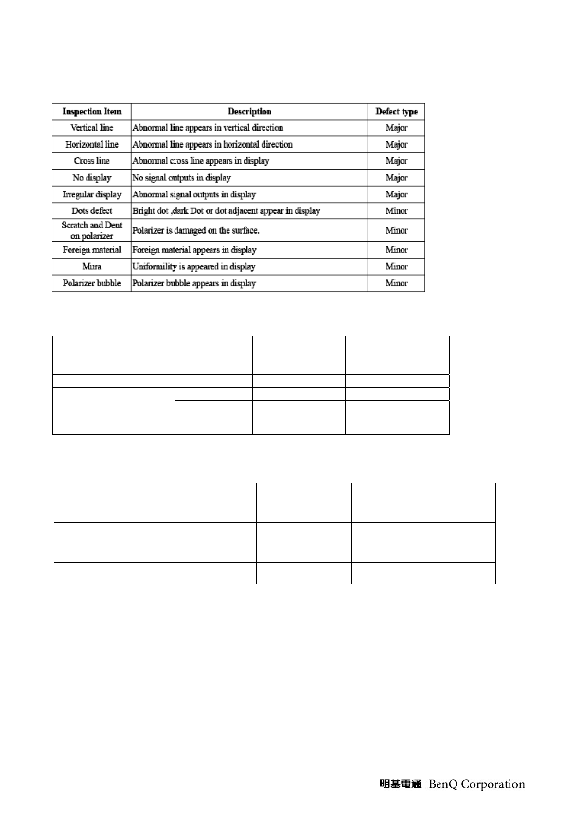
1.0 Panel electrical inspection specification:
Inspection Item Specification
1 Line defect Can’t be seen.
2 Random dot defect
Bright dot ≦3 dots
2 dots adjacent </=1
Random </=5 dots
2 dots adjacent </=2
3. Dark dot
3 dots adjacent </=0
Minimum Distance Between Dark dots L >/=5mm
Total bright and dark dot
4.
N</=5
Foreign Black /White /
5.
Bright sport
Foreign Black /White /
6.
Bright Lint
0.15</=D </= 0.5mm,N</=5
0.07<W</=0.1mm,2<L</=5mm,N</=5
Judged by 8% ND Filter in 50% gray pattern (If both customer and CMO
7. Mura
agree mutually , CMO will set up limit sample and apply to the criteria
with the customer)
Function al failure
( V-line/H-line /Cross line
8.
Not allowable
etc.)
9. polarizer Scratches 0.07<W</=0.1mm,2<L</=5mm,N</=5
10. Dent/Air Bubble 0.15</=D </= 0.5mm,N</=5
Note)
1. For pixel defect, one sub pixel is defined for one pixel.
2. Follow Panel spec
38
Page 39

Software/Firmware Upgrade Process
How to enter Factory OSD
1. Please press keypad to enter Factory Mode.
2. Press “Enter” key + “Up” key together and then press “Power” key to enter Factory Mode
3. Confirm software version
39
Page 40

Software download procedure
The ISP SOP FOR MST
1. Connection PC to the Tv set by the tool as the follow picture (Fig.1~4)
Action: The D_SUB cable must be 15 pin, and the TV set must be AC ON
Fig.1
Fig.2
40
Page 41

Fig.3
Fig.4
41
Page 42

1: Installation Driver
Fig.1
Press the “next” button to continue.
Fig.2
42
Page 43

Fig.3
Now press the “确定“button.
Fig.4
Press the “close”,the driver installation ok.
43
Page 44

2. Start the Isp
1. Open the “ISP_Tool_410_T.exe”
2. Press the “config”, if the the ISP board have been found, you will see the picture as bellow.
Fig.5
3. Press the “Connect”, if all the things are ok and ready, it will show the device type as the bellow
picture. Then pres “確定”
Fig.6
44
Page 45

4. Press “read” and choose the right F/W .
Fig.7
5. Press “Auto”, than press “Run”. It will start ISP . When the ISP is ok ,you will see the information as
the bellow picture.
Fig.8
6. Pull away the AC power Cord and the D-SUB Cable. And start another TV set.
7. When we start another TV set with AC ON, we only need to press the “RUN”.
45
Page 46

Adjustment / Alignment Procedure
1. Preparation:
1. Approximately 30 minutes should be allowed for warm up before proceeding.
2. Adjustments should be undertaken only on those necessary elements since most of them have
been carefully preset at the factory.
3. ESD protection is needed before adjustment.
2. PC Auto Timing Check:
(1) Timing list
(2) Setup input timing
(3) Select timing from above timing list
(4) If position is wrong, press “Auto Adjust” function at OSD to check this function
EEPROM INIT
A. Timing: 1920X1080@60Hz.
B. Pattern: Cross hatch.
C. Tune on the set and press the “▲” and “enter” key simultaneously, then press “power” key.
At this time we can enter into the factory mode.
D. Select the “EEPROM INIT” item and press “enter”key to reset the EEPROM.
3. RGB Color Temperature adjusting :
A. Timing: 1920X1080@60Hz.
B. Pattern: 5 mosaic.
C. Set CA210 color analizer at the center of screen and along a perpendicular to the screen near the
display.
D. In the factory mode select the “SOURCE” item, then select :PC.
E. Press “▼” key to select the “ CTemp BALANCE” item and press “enter ”key, then the white
balance will be auto adjusted .
46
Page 47

4. YPbPr MODE Color Temperature adjusting :
x
y
x
y
W
x
y
A. Timing: 1920X1080@60Hz.
B. Pattern: COLOR BAR.
C. Set CA210 color analizer at the center of screen and along a perpendicular to the screen near the
display.
D. In the factory mode select the “SOURCE” item, then select :YPbPr.
E. Press “▼” key to select the “ CTemp BALANCE” item and press “enter ”key, then the white
balance will be auto adjusted .
5. Spec and Table list
Reference: The variance of color coordinate via Red, Green, Blue :
Table 1-1,1-2,1-3 : Color temperature spec, default Color temp at COOL.
Table 1-1
Color temp item
@factory OSD
Color
temperature
P-N/V-N
Normal
-
0.295±0.02
0.311±0.02
Table 1-2
Color temp item
@factory OSD
Color
temperature
P-C/V-C
Cool(default)
-
0.285±0.02
0.299±0.02
Table 1-3
Color temp item
@factory OSD
Color
temperature
P-W/V-
Wa rm
-
0.313±0.02
0.329±0.02
6. HDMI MODE FUNCTION TEST
A.DVI MODE: Depend on the TIMING of TIMING TABLE (TABLE 3 ) to check MODE in order.
B.HDMI MODE: make sure the 480i, 480p, 720p, 1080i ,1080p TIMING is right.
7 .OSD FUNCTION TEST
A. Time: 1920x1080@60Hz
B. Pattern: 16*12 pane
C. Make sure that Each FUNCTION has one right action.
47
Page 48

8. YPbPr, S-VIDEO, AV, TV, FUNCTION TEST
A. Input YPbPr, S-VIDEO, AV , TV, signal and check.
B. Input PAL D/K air channel (TABLE 1) for TV channel.
C. Under YPbPr MODE, Make sure the 480i, 480P, 720P, 1080i ,1080p is right.
9. AUDIO FUNCTION TEST
A. Audio input includes PC AUDIO IN, S-VIDEO/AV AUDIO IN and YPbPr AUDIO IN.
B. Under PC MODE, input PC AUDIO signal, checks whether the action of AUDIO IN is right.
C. Under S-VIDEO/AV MODE, input L/R AUDIO signal, checks whether the action of AUDIO IN is
right.
D. Under YPbPr MODE, input L/R AUDIO signal, checks whether the action of AUDIO IN is right.
E. Under HDMI MODE, checks whether the action of AUDIO IN is right.
F. AUDIO OUT FUNCTION TEST: Under all patterns except PC,HDMI,YPbPr pattern, The Audio
output meets active extra speaker, examines whether the extra speaker makes the sound.
48
Page 49

Level 2 Circuit Board and Standard Parts Replacement
Exploded View
49
Page 50

EXPLODED VIEW PARTS LIST
Ref. No. Source DESCRIPTION SPECIFICATION Q‘TY REMARK
1F01 FRONT BEZEL
1F02 LED INDIC.-PWR JC236B UT-0520T COLOR T57015 1
1F03 IR COVER JC236B PC GE-121R-21051 1
1F04 FUNCTION KEY JC229A ABS 94HB BLACK C 1
1F05 NAME PLATE 26x7.4mm Material Sticker BenQ 1
1F08 SCREW BND T+ M3X8(BND T+) 3
2C01 CABI BACK JC240A ABS 94HB BLACK C (TAIWAN)(ENGLISH) 1
2C02 BRACKET FIX JT198QP SECC 0.8T WALL MOUNT 1
5B01 NECK JC236A ABS 94HB BLACK C 1
5B02 HINGE N2430P SECC T=2.0°~20° 50KG-CM 1
5B03 SCREW P SW+ M4*12 PSW+ 4
5B04 STAND JT229HP J-STAND ABS HB (G.L BLACK/MT11010) 1
5B05 SCREW BND T+ M4X16(BND T+) 4
5B06 FOOT PAD
5F01 METAL FITTG JC236 PANEL SECC T=0.6mm TAIWAN 1
5F02 SCREW M3*5MM 4
5F03 SCREW BND T+ M3X8(BND T+) 2
5F04 SCREW BND T+ M4X10(BND T+) 4
5F05 SCREW SPE ISZZTER001A M3*6L MSWR17/FZMYI 6
5F06 SCREW M3X6 P=0.5 4
5F07 SCREW SPE ISZZTER001A M3*6L MSWR17/FZMYI 2
5F08 BRACKET FIX SE2221 TUNER BOX BKT SECC 0.6T 1
5F09 SCREW SPE ISZZTER001A M3*6L MSWR17/FZMYI 4
5F10 SHIELD PLATE JC236 SPTE T=0.3 TAIWAN 1
5F11 SCREW BND T+ M3X8(BND T+) 3
5F12 SCREW M3X6 P=0.5 1
5F13 SCREW SPE STAND-OFF HEX #4-40UNC H5*5*7L 2
5F14 BRACKET FIX N2430P FOR HINGE T=1.0mm 1
5F15 SCREW M3X6 P=0.5 2
5F16 SCREW SPE ISZZTER001A M3*6L MSWR17/FZMYI 2
5F17 METAL FITTG-I/O JC240A&B IO-SIDE SECC 0.3T (TAIWAN) 1
5F18 DUST COVER VT2430 ABS 94HB BLACK C IO-SIDE COVER (TAIWAN) 1
5F19 DUST COVER VT2430 ABS 94HB BLACK C TUNNER BOX COVER 1
5F20 SCREW M3X6 P=0.5 2
5F21 SCREW M3X8 P=0.5 BLACK 1
5F25 SPONGE SPONGE BLACK 20*15*50MM 1
6B01 SCREW BND T+ M4X10(BND T+) (BLK) 4
6B03 SCREW M3*6 P=0.5 BLACK 5
6B04 DUST COVER N2430P ABS 94HB BLACK C 1
6B05 SCREW FMS+ M3*6 ZN-BLACK 1
JC240B ABS 94HB G.L BLACK C FOR BENQ(HDMI
HDTV)(MK2432)
φ20*3.0T SQUARE GRAIN BLK
1
4
50
Page 51

Disassembly / Assembly
Disassembly of Stand from LCD TV.
1.
1.1 Unscrew 4 screws to move Stand Unit and Dust Cover.
Dust Cover
2. Disassembly of Rear Cover.
2.1 Unscrew 10 screws in the Rear Cover.
Stand
51
Page 52

2.2 Prize the rectangle hole on Rear Cover (Fig.1) with a screwdriver (Fig.2) to make the Rear Cover detach from the
LCD TV.
Fig.1 Fig.2
Rear Cover
52
Page 53

3. Disassembly of Main Board, Power Board, Front Cover and Panel Unit.
3.1. Unscrew 2 screws to remove Bracket fix.
Bracket fix
3.2. Unscrew 8 screws to move Speaker and KeyPad Board .
53
Page 54

Speaker
KeyPad Board
3.3. Unscrew screws 6 to move Shield Plate .
3.4. Unscrew 4 screws to remove Front Cover.
Shield Plate
Front Cover
54
Page 55

3.5. Unscrew 4 screws and disconnect the wires to remove Main Board.
Main Board
3.6. Unscrew 6screws and disconnect the wires to remove Power Board.
Power Board
55
Page 56

3.7. Unscrew 4 crews to move Panel Bracket .
Panel Bracket
56
Page 57

System Block Diagram
The LCD TV uses 1920x1080 LCD Panel to display image.
This LCD TV can accept the following input sources:
(1) HDMI connector
(2) D-SUB connector
(3) PC audio
(4) Component
(5) S-Video
(6) Composite
(7) Audio In*2 (L/R)
(8) Audio Out (L/R)
(9) Earphone
(10) TV Tuner
(11) DTV-NA
As shown in the system block diagram, there are 5 boards in the system. They are:
(1) Main Board
(2) Keypad Board
(3) Power board
(4) IR board
(5) Tuner connect board
In the main board circuits, it contains Scalar (MST97889DLD) & Audio Amp(YDA148).
57
Page 58

Troubleshooting
58
Page 59

NO display
59
Page 60

Appendix 1 – Screw List /Torque
ITEM DESCRIPTION SPECIFICATION Q‘TY
ISZZTER001A M3*6L
MSWR17/FZMYI
ISZZTER001A M3*6L
1
2
3
4
5
6
7
8
9
10
11
12
SCREW SPE
SCREW SPE
SCREW M3*5MM 4 4~6Kgf/cm Metal fittg to panel 4
SCREW
SCREW M3*6 P=0.5 BLACK 5 5~6Kgf/cm Lock up to back cover 5
SCREW M3X8 P=0.5 BLACK 1 5~6Kgf/cm Lock up to I/O cover 1
SCREW FMS+ M3*6 ZN-BLACK 1 5~6Kgf/cm Lock up to back cover 1
SCREW BND T+
SCREW BND T+ M4X10(BND T+) 4 6~8Kgf/cm Metal fittg to front bezel 4
SCREW BND T+ M4X10(BND T+) (BLK) 4 6~8Kgf/cm Lock up to back cover 4
SCREW BND T+ M4X16(BND T+) 4 8~10Kgf/cm Hinge to arm 4
SCREW P SW+ M4*12 PSW+ 4 8~10Kgf/cm Hinge to bracket fix 4
MSWR17/FZMYI
ISZZTER001A M3*6L
MSWR17/FZMYI
ISZZTER001A M3*6L
MSWR17/FZMYI
STAND-OFF HEX #4-40UNC
H5*5*7L
M3X6 P=0.5
M3X6 P=0.5 5~7Kgf/cm Lock up to HDMI connector 1
M3X6 P=0.5 5~6Kgf/cm Bracket fix to metal fittg 2
M3X6 P=0.5 5~6Kgf/cm I/O cover to metal fittg 2
M3X8(BND T+)
M3X8(BND T+) 5~7Kgf/cm Metal fittg to front bezel 2
M3X8(BND T+) 5~7Kgf/cm Lock up to AV connector 3
14
2 5~7Kgf/cm Lock up to VGA connector 2
9
7
TORQUE
(KG-CM)
5~6Kgf/cm Power board to metal fittg 6
5~6Kgf/cm Ground plate to metal fittg 2
5~7Kgf/cm mainboard to metal fittg 4
5~6Kgf/cm TUNER CON/B to tuner box bracket 2
5~7Kgf/cm Tuner box bracket to metal fittg 4
4~6Kgf/cm Keypad to front bezel 2
WHERE USE Q‘TY
60
Page 61

Appendix 2 –IR Code
Code format: RC5
Customer Code: 3010
System Code: 00
61
Page 62

Appendix 3 – Wall Mount Dimension
Scale: 1:1
Unit: mm
62
 Loading...