

D
Bedienungsanleitung
Operating manual
F
Mode d‘emploi
Návodkpoužitízkoušečky
Käyttöohje
Οδηγίεςχρήσεως
I
Istruzioniperl’uso
Gebruiksaanwijzing
Instrukcjaobsługi
BENNING VT 1
D
Bedienungsanleitung
Operating manual
F
Mode d‘emploi
Gebruiksaanwijzing
Mehrsprachige Anleitung unter
BENNING VT 1
www.benning.de
Multilingual manuals at
D F I
A
1
2
08/ 2020
3
4
BENNING VT 1
3
D F I
230 V
B
C
AC
PE
N L
08/ 2020
BENNING VT 1
4

D
Bedienungsanleitung
BerührungsloserPhasen-undKabelbruchprüfer
BENNING VT 1
Bevor Sie den Phasen-/Kabelbruchprüfer BENNING VT 1 benutzen: Lesen Sie bitte die Bedienungsanleitung und beachten Sie unbedingt die Sicherheitshinweise!
1. Sicherheitshinweise:
- Unmittelbar vor und nach dem Benutzen den Phasen-/Kabelbruchprüfer auf Funktion prüfen!
(siehe Abschnitt 3). Das Gerät darf nicht benutzt werden, wenn die Funktion einer oder mehrerer
Anzeigen ausfällt oder keine Funkti onsbereitschaft zu erkennen ist!
- Gerät beim Prüfen nur an dem roten Griff hinter der Griffbegrenzung 2 anfassen und die weiße
Prüfspitze 1 nicht berühren!
- Das Gerät darf nur im angegebenen Nennspannungsbereich von 200 V - 1000 V AC und in geerdeten Netzstromkreisen der Überspannungskategorie CAT III 1000 V bzw. CAT IV 600 V Leiter
gegen Erde benutzt werden.
- Der Phasen-/Kabelbruchprüfer BENNING VT 1 erkennt Felder von Phasen-/Außenleiterspannungen ab ca. 200 V Wechselspannung (AC). Felder von Gleichspannungen (DC) werden nicht
erkannt!
- Beachten Sie, dass Arbeiten an spannungsführenden Teilen und Anlagen grundsätzlich gefährlich
sind. Bereits Spannungen ab 30 V AC und 60 V DC können für den Menschen lebensgefährlich
sein.
- Mit dem Phasen- und Kabelbruchprüfer BENNING VT 1 kann nicht die Spannungsfreiheit von
einem Anlagenteil festgestellt werden; verwenden Sie dazu einen zweipoligen Spannungsprüfer,
z. B. DUSPOL®, um das Feststellen der Spannungsfreiheit zu bestimmen.
- Folgende Faktoren können die korrekte Funktionsweise der Phasen- und Kabelbruchprüfung negativ beeinflussen:
- zu großer Abstand zur prüfenden Phase (Außenleiter)
- zu starke Isolierung und Abschirmung der Phase (Außenleiter)
- Schutzkleidung und isolierende Standortgegebenheiten
- Konstruktive Unterschiede von Steckdosen/CEE-Kupplungen mit zurückliegenden Kontakten,
z.B. 63 A CEE-Kupplung
- Netzstörungen oder mangelnde Netzqualität
- Zustand der Batterien
- Gerät nicht mit geöffnetem Batterieschacht betreiben.
- Das Gerät ist für die Anwendung durch Elektrofachkräfte in Verbindung mit sicheren Arbeitsverfahren ausgelegt.
- Das Gerät ist vor Verunreinigungen und Be schädigungen der Gehäuseoberfläche zu schützen.
Elektrische Symbole auf dem Gerät:
Symbol Bedeutung
Achtung Dokumentation beachten!
Das Symbol gibt an, dass die Hinweise in der Bedienungsanleitung zu beachten sind,
m
um Gefahren zu vermeiden
08/ 2020
BENNING VT 1
5

D
Dieses Symbol auf dem Gerät bedeutet, dass der BENNING VT 1 schutzisoliert
(Schutzklasse II) ausgeführt ist.
Wechselspannung
AC
Erde (Spannung gegen Erde)
Dieses Symbol zeigt die Ausrichtung der Batterien zum polrichtigen Einlegen an
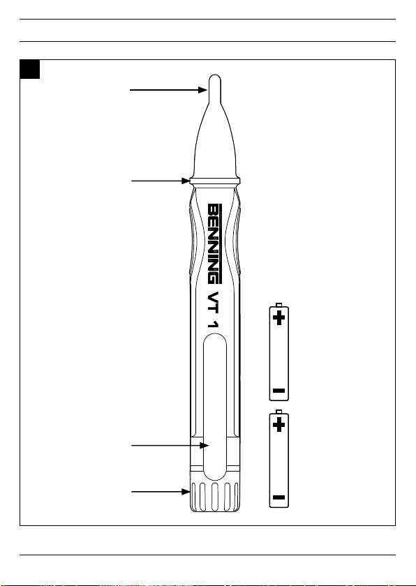
2. Gerätebeschreibung(Bild A)
1
PrüfspitzemitLED-Anzeige (rot)
2
Griffbegrenzung
3
Clip
4
Batteriefachdeckel
3. Funktionsprüfung
- Unmittelbar vor und nach dem Benutzen den Phasen-/Kabelbruchprüfer auf Funktion prüfen!
- Testen Sie die Funktion der Phasenprüfung an einer bekannten Spannungsquelle z.B. 230 V Steckdose/5-polige CEE Steckdose.
- Der Batteriewechsel ist erforderlich, wenn die rote LED-Anzeige 1 oder der Signalton schwach
werden.
- Verwenden Sie den BENNING VT 1 nicht, wenn nicht alle Funktionen einwandfrei funktionieren!
- Der BENNING VT 1 besitzt keinen Ausschalter und ist immer aktiv. Eine spezielle Schaltung mit
geringer Stromaufnahme verlängert die Batterielebensdauer und somit Einsatzbereitschaft.
4. Funktionsweise
- Der Phasen-/Kabelbruchprüfer BENNING VT 1 erkennt elektrische Felder die von Phasen-/Außenspannungen ab 200 V - 1000 V AC (45 Hz - 65 Hz) erzeugt werden.
- Wird ein elektrisches Feld erfasst, leuchtet die Prüfspitze 1 rot auf und ein Signalton ertönt. Die
Blinkfrequenz der roten Prüfspitze 1 und die Signaltonfrequenz steigt mit zunehmender Höhe des
elektrischen Feldes bzw. der anliegenden Spannung.
- Der Phasen-/Kabelbruchprüfer BENNING VT 1 kann benutzt werden um die Phase (Außenleiter)
einer Wechselspannung zu bestimmen.
- Für die Prüfung ist kein Stromfluss und keine elektrisch leitende Kontaktierung mit dem Anlageteil,
der Steckdose oder der isolierten Leitung nötig.
- Beachten Sie, dass der BENNING VT 1 nur auf ausreichend starke Felder ab 200 V AC Phasen-/
Außenleiterspannung reagiert.
Sollte der Phasen-/Kabelbruchprüfer BENNING VT 1 nicht reagieren, könnte der Abstand zum spannungsführenden Anlageteil zu groß sein oder das Anlageteil ist abgeschirmt bzw. die Isolierung ist zu
dick.
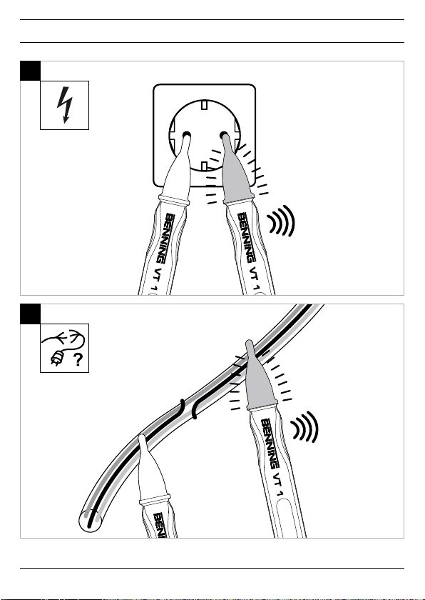
5. Phasen-/AußenleiterprüfungeinerWechselspannung(Bild B)
- Positionieren Sie die Prüfspitze 1 an die vermutete Phase (Außenleiter) des Anlageteils.
- Das Anliegen der Phase (Außenleiter) wird über ein Signalton und das rote Aueuchten der Prüfspitze 1 angezeigt.
Achtung!
Beachten Sie, auch wenn der BENNING VT 1 keine Phase (Außenleiter) signalisiert, kann an dem
Prüfobjekt trozdem eine gefährliche Spannung anliegen. Zur Feststellung der Spannungsfreiheit ver-
08/ 2020
BENNING VT 1
6

D
wenden Sie bitte ausschließlich einen zweipoligen Spannungsprüfer gemäß DIN EN 61243-3 (VDE
0682-401) z.B. einen DUSPOL® - Spannungsprüfer.
6. PrüfungaufUnterbrechungspannungsführenderLeitungen (Bild C)
Um Unterbrechungen an spannungsführenden Leitungen (z.B. Kabelbruch in Kabeltrommel oder defekte Lampen in Lichterketten) zu lokalisieren, führen Sie die Prüfspitze 1 entlang der isolierten Leitung von der Einspeisestelle (Phase) Richtung dem anderen Leitungsende. Die Unterbrechungsstelle
ist lokalisiert, sobald die Phase (Außenleiter) nicht mehr über den Signalton und das Aueuchten der
Prüfspitze erkannt wird.
Bei der Prüfung einer Kabeltrommel ist zu beachten, dass der Schutzkontaktstecker um 180 ° gedreht werden muss um beide Leitungen an die Phase (Außenleiter) einer Schutzkontaktsteckdose
anzuschließen.
7. Batteriewechsel(Bild A)
- Gerät bei oenem Batteriefach nicht an Spannung legen!
- Den Batteriefachdeckel 4 vom Gerät schrauben und die verbrauchten Batterien aus dem Gerät
entnehmen.
- Neue Batterien des Typs Micro (LR03/AAA) polrichtig (Pluspol voran) in das Gerät stecken.
- Batteriefachdeckel 4 auf das Gehäuse schrauben.
8. TechnischeDaten:
- Vorschrift: DIN EN 61010-1, DIN EN 61326
- Nennspannungs-/Frequenzbereich: 200 V - 1.000 V AC/45 Hz - 65 Hz
- Überspannungskategorie: CAT III 1.000 V/CAT IV 600 V
- Verschmutzungsgrad: 2
- Schutzart: IP 40 (DIN VDE 0470-1 IEC/ EN 60529)
4 - erste Kennzier: Schutz gegen Zugang zu gefährlichen Teilen und Schutz gegen feste Fremd-
körper, > 1,0 mm Durchmesser
0 - zweite Kennzier: Kein Wasserschutz,
- Betriebstemperaturbereich: 0 °C bis + 40 °C, Luftfeuchte ≤ 80%,
- Lagertemperaturbereich: - 20 °C bis + 60 °C, Luftfeuchte ≤ 80% (ohne Batterien)
- Geräteabmessungen (L x B x H): ca. 152 x 22 x 18 mm
- Gewicht: ca. 40 g (inkl. Batterien)
- Batterietyp: 2 x Micro, LR03/AAA (1,5 V)
Der Phasen-/Kabelbruchprüfer BENNING VT 1 ist bei leerer Batterie nicht funktionsfähig!
9. AllgemeineWartung
Reinigen Sie das Gehäuse äußerlich mit einem sauberen tro ckenen Tuch.
Falls Verunreinigungen oder Ablagerungen im Bereich der Batterie oder des Batteriegehäuses vorhanden sind, reinigen Sie auch diese mit einem trockenen Tuch. Entfernen Sie bei längerer Lagerung die
Batterien aus dem Gerät!
10. Umweltschutz
Bitte führen Sie verbrauchte Batterien und das Gerät am Ende seiner Lebensdauer den zur
Verfügung ste hen den Rückgabe- und Sammelsystemen zu.
08/ 2020
BENNING VT 1
7

D
11. Produktsupport
Für weiterführende Auskünfte stehen Ihnen die Fachleute des Lieferanten bzw. des Herstellers zur
Verfügung.
BENNING Elektrotechnik und Elektronik GmbH & Co. KG
Service Center
Robert-Bosch-Str. 20
D - 46397 Bocholt
Service-Hotline: +49 (0) 2871 / 93 – 555
Zentrale: +49 (0) 2871 / 93 - 0
Fax: +49 (0) 2871 / 93 - 429
Internet: www.benning.de • E-Mail: duspol@benning.de
08/ 2020
BENNING VT 1
8

Operating Manual
Non-ContactPhaseIndicatorandCableBreakDetector
BENNING VT 1
Before using the BENNING VT 1 phase indicator and cable break detector: Please read the operating
manual and absolutely observe the safety instructions!
1. Safetyinstructions
- Check the phase indicator and cable break detector for correct functioning immediately before and
after using it (see chapter 3)! Do not use the indicator, if one or more indications are not working or
if it does not seem to be ready for operation!
- During the tests, touch the indicator at the red handle behind the grip limit 2 only and do not touch
the white probe tip 1!
- The indicator must be used only within the stated nominal voltage range from 200 V to 1,000 V AC
and in earthed mains supply circuits of overvoltage cat egory CAT III 1,000 V or CAT IV 600 V for
phase-to-earth measurements.
- The BENNING VT 1 phase indicator and cable break detector detects fields of phase/external
conductor voltages from approx. 200 V alternating voltage (AC) on. Direct voltage (DC) fields will
not be detected!
- Please observe that work on live parts and electrical components of all kinds is dangerous! Even
low voltages of 30 V AC and 60 V DC may be dangerous to human life!
- The BENNING VT 1 phase indicator and cable break detector is not a substitute for a two-pole
voltage tester such as e.g. the DUSPOL® to determine the ab sence of voltage.
- The following factors might affect the correct functioning of the phase test and cable break detect:
- excessive distance to the phase (external conductor) to be tested
- excessive insulation and shielding of the phase (external conductor)
- protective clothing and insulating conditions on site
- constructional differences of sockets / CEE couplings with recessed contacts, e.g. 63 A CEE
coupling
- mains failures or lacking mains quality
- battery condition
- Do not operate the device with the battery compartment being open.
- The indicator is designed for being used by qualified electricians and under safe working conditions.
- The indicator must be protected against contamination and damaging of the housing surface.
Electrical symbols on the device:
Symbol Meaning
Attention! Please observe documentation!
This symbol indicates that the information provided in the operating manual must be
m
complied with in order to avoid risks.
This symbol on the BENNING VT 1 indicates that the indicator is equipped with protective insulation (protection class II).
Alternating voltage
AC
08/ 2020
BENNING VT 1
9

Earth (voltage to earth)
This symbol shows the orientation of the batteries for inserting them with correct polarity.
2. Devicedescription (figure A)
1
ProbetipwithLEDindication (red)
2
Grip limit
3
Clip
4
Batterycompartmentcover
3. Functional test
- Check the phase indicator and cable break detector for correct functioning immediately before and
after using it!
- Test the phase test for correct functioning with a familiar voltage source, e.g. a 230 V socket/5-pin
CEE socket.
- Please replace the batteries as soon as the red LED indication 1 or the acoustic signal are getting
weaker.
- Do not use the BENNING VT 1, if not all functions are working properly!
- The BENNING VT 1 has no circuit breaker and is always enabled. A special circuit with low current
consumption extends the battery lifetime and thus ensures that the device is ready for use.
4. Howtheindicatorworks
- The BENNING VT 1 phase indicator and cable break detector detects electric fields generated by
phase/external conductor voltages from 200 V to 1,000 V AC (45 Hz to 65 Hz) on.
- If an electric field is detected, the probe tip 1 lights up in red color and an acoustic signal is emitted. The flashing frequency of the red probe tip 1 as well as the frequency of the acoustic signal
increase with the electric field or the voltage applied increasing as well.
- The BENNING VT 1 phase indicator and cable break detector can be used to determine the phase
(external conductor) of an AC voltage.
- The test does not require any current flow and no electrically conductive contact with the system
part, socket or insulated line.
- Please observe that the BENNING VT 1 only responds to sufficiently strong fields with a phase/
external conductor voltage from 200 V AC on.
If the BENNING VT 1 phase indicator and cable break detector does not react, the distance to the live
system part might be too large, the system part might be shielded or the insulation might be too thick.
5. Phase/externalconductortestofanACvoltage (figure B)
- Place the probe tip 1 onto the assumed phase (external conductor) of the system part.
- If the phase (external conductor) has been detected, this is confirmed by an acoustic signal and by
the probe tip 1 lighting up in red color.
Attention!
Please observe that even if the BENNING VT 1 does not indicate a phase (external conductor), a dangerous voltage may be applied to the test object nevertheless. For determining the absence of voltage,
only use a two-pole voltage tester complying with the DIN EN 61243-3 (VDE 0682-401) standard, e.g.
a DUSPOL® voltage tester.
08/ 2020
BENNING VT 1
10

6. Testingofinterruptionsoflivelines(figure C)
To localize interruptions of live lines (e.g. a cable break in a cable reel or defective lamps in a chain of
lights), pass the probe tip 1 along the insulated line from the feeding point (phase) in direction of the
other end of the line. The point of interruption is located as soon as the phase (external conductor) is
no longer indicated by the acoustic signal and the test probe lighting up.
For testing a cable reel, make sure to turn the shock-proof plug by 180° in order to connect both lines
to the phase (external conductor) of a shock-proof socket.
7. Batteryreplacement (figure A)
- Do not apply voltage to the device when the battery compartment is open!
- Remove the battery compartment cover 4 from the indicator and remove the used batteries.
- Insert new micro batteries (LR03/AAA) into the indicator observing correct polarity (positive pole
first).
- Screw the battery compartment cover 4 back onto the indicator.
8. Technicaldata
- regulation: DIN EN 61010-1, DIN EN 61326
- nominal voltage/frequency range: 200 V to 1,000 V AC/45 Hz to 65 Hz
- overvoltage category: CAT III 1,000 V/CAT IV 600 V
- contamination level: 2
- protection category: IP 40 (DIN EN 60529) means:
Protection against access to dangerous parts and protection against solid impurities of a diameter
> 1.0 mm, (4 - first index).
No protection against water, (0 - second index).
- operating temperature range: - 0 °C to + 40 °C, air humidity ≤ 80 %
- storage temperature range: - 20 °C to + 60 °C, air humidity ≤ 80% (without batteries)
- dimensions of the indicator (L x W x H): approx. 152 x 22 x 18 mm
- weight: approx. 40 g (incl. batteries)
- battery type: 2 x micro, LR03/AAA (1.5 V)
The BENNING VT 1 phase indicator and cable break detector does not work with the battery being
exhausted!
9. General maintenance
Clean the exterior of the device with a clean dry cloth.
If there is contamination or deposits in the area of the battery or the battery housing, clean these areas
as well by means of a dry cloth. If the device is stored for a longer period of time, remove the batteries
from the device!
10. Environmental protection
At the end of product life, dispose of the unserviceable device as well as used batteries via
appropriate collecting facilities provided in your community.
08/ 2020
BENNING VT 1
11

11. Productsupport
Please contact the expert personnel of the supplier or manufacturer for further information.
BENNING Elektrotechnik und Elektronik GmbH & Co. KG
Service Center
Robert-Bosch-Str. 20
D - 46397 Bocholt
Service hotline: +49 (0) 2871/93 - 555
Head office: +49 (0) 2871/93 - 0
Fax: +49 (0) 2871/93 - 429
Internet: www.benning.de • E-mail: duspol@benning.de
08/ 2020
BENNING VT 1
12

F
Mode d‘emploi
dudétecteurdephaseetderuptures
de câble sans contact
BENNING VT 1
Avant d‘utiliser le détecteur de phase et de ruptures de câble BENNING VT 1: Lisez le mode d‘emploi
et tenez impérativement compte des consignes de sécurité !
1. Consignesdesécurité:
- Contrôlez toujours le bon fonctionnement du détecteur de phase/d‘ordre de phases immédiatement avant et après de l‘utiliser ( voir paragraphe 3 ) ! Le détecteur ne doit pas être utilisé dès lors
qu‘une ou plusieurs affichages ne fonctionnent plus ou dès lors l‘appareil n‘est plus opérationnel !
- Lors du contrôle, ne prenez le détecteur que par la poignée rouge derrière la surface de prise
limitée 2 et ne touchez pas la pointe d‘essai blanche 1 !
- Le détecteur ne doit être utilisé que dans la plage de tension nominale spécifiée de 200 V à
1.000 V AC et dans les circuits électriques de secteur mis à la terre de la catégorie de surtension
CAT III 1.000 V ou CAT IV avec des conducteurs de 600 V par rapport à la terre.
- Le détecteur de phase et de ruptures de câble BENNING VT 1 sert à détecter des champs des
tensions de phase/tensions composées à partir de 200 V AC environ. Les champs des tensions
continues ( DC ) ne sont pas détectés !
- Tenez compte du fait qu‘il est toujours dangereux de travailler sur les com posants et sur les installations sous tension. Déjà les tensions à partir de 30 V AC et 60 V DC peuvent être mortelles !
- Le détecteur de phase et de ruptures de câble BENNING VT 1 ne sert pas de substitut d‘un
contrôleur de tension bipolaire comme par exemple le DUSPOL® afin de déterminer l‘absence de
tension.
- Les facteurs suivants pourraient affecter le bon fonctionnement du test de phase et du test de
ruptures de câble :
- une distance trop grande à la phase ( conducteur extérieur ) à contrôler
- une isolation trop forte ou un blindage trop fort de la phase ( conduc teur extérieur )
- vêtements protecteurs et conditions isolantes sur site
- différences quant à la construction des prises de courant / coupleurs CEE avec des contacts
en retrait comme par ex. un coupleur CEE 63 A
- pannes de secteur ou qualité insuffisante du secteur
- état des piles
- N‘utilisez jamais l‘appareil si le compartiment à piles est ouvert.
- Le détecteur est conçu afin d‘être utilisé par des électrotechniciens en combinaison avec des
procédés de travail sûrs.
- Protégez le détecteur contre les impuretés ainsi que contre l‘endommage ment de la surface du
boîtier.
Symboles électriques sur l‘appareil :
Symbole Signication
Attention ! Tenir compte de la documentation !
Ce symbole indique qu’il faut tenir compte des instructions contenues dans ce mode
m
d’emploi an d’éviter tout risque.
08/ 2020
BENNING VT 1
13

F
Ce symbole sur l‘appareil signie que le BENNING VT 1 est doté d‘une isolation double
( classe de protection II ).
Tension alternative
AC
Terre (tension par rapport à la terre)
Ce symbole montre l‘orientation des piles an de les insérer en respectant la polarité
correcte.
2. Descriptiondel‘appareil ( gure A )
1
Pointed‘essaiavecindicationparLED ( rouge )
2
Surfacedepriselimitée
3
Clip
4
Couvercle du compartiment à piles
3. Contrôledefonctionnement
- Contrôlez toujours le bon fonctionnement du détecteur de phase et de ruptures de câble immédiatement avant et après de l‘utiliser !
- Testez le bon fonctionnement du test de phase sur une source de tension connue comme par ex.
une prose de courant 230 V/prise de courant CEE à cinq broches.
- Il est nécessaire de remplacer les piles dès lors que l‘affichage LED rouge 1 ou le signal acoustique deviennent faible.
- Le BENNING VT 1 ne doit plus être utilisé si une ou plusieurs des fonc tions ne fonctionnent pas
correctement !
- L‘appareil BENNING VT 1 n‘est pas pourvu d‘un disjoncteur et est toujours activé. Un circuit spécifique à faible consommation de courant prolonge la durée de vie des piles et donc la disponibilité
opérationnelle.
4. Fonctionnement
- Le détecteur de phase et de ruptures de câble BENNING VT 1 sert à détecter des champs électriques générés par les tensions de phase/tensions composées à partir de 200 V jusqu‘à 1.000 V
AC (45 Hz à 65 Hz).
- Si l‘appareil détecte un champ électrique, la pointe d‘essai rouge 1 s‘al lume et un signal acoustique est émis. La fréquence de clignotement de la pointe d‘essai 1 et la fréquence du signal
acoustique augmentent avec l‘hauteur du champ électrique ou de la tension appliquée.
- Le détecteur de phase et de ruptures de câble BENNING VT 1 sert à déterminer la phase
( conducteur extérieur ) d‘une tension alternative.
- Pour le test, on n‘a pas besoin d‘un flux de courant ou d‘un contact électro conducteur avec le
composant, la prise de courant ou la ligne isolée.
- Tenez compte du fait que le BENNING VT 1 ne réagit qu‘aux champs suffisamment forts d‘une
tension de phase/tension composée à partir de 200 V AC.
Au cas où le détecteur de phase et de ruptures de câble BENNING VT 1 ne répondrait pas, soit la
distance au composant conducteur est trop grand, soit le composant est blindé, soit l‘isolation est trop
épais.
5. Contrôledephase/duconducteurextérieurd‘unetensionalternative ( gure B )
- Reliez la pointe d‘essai 1 à la phase supposée ( conducteur extérieur ) du composant.
- Un signal acoustique est émis et la pointe d‘essai 1 s‘allume en couleur rouge lorsque la phase
08/ 2020
BENNING VT 1
14

F
( conducteur extérieur ) est présente.
Attention!
Tenez compte du fait qu‘une tension dangereuse peut être présente à l‘objet de contrôle même si le
BENNING VT 1 ne signale pas la présence d‘une phase ( d‘un conducteur extérieur ). An de déterminer l‘absence de tension, n‘utilisez qu‘un contrôleur de tension bipolaire conformément à la norme DIN
EN 61243-3 ( VDE 0682-401 ) comme par exemple un contrôleur de tension DUSPOL®.
6. Contrôle de interruptions de lignes conductrices ( gure C )
An de localiser les interruptions de lignes conductrices ( par ex. des ruptures de câble aux enrouleurs
de câble ou des lampes défectueuses aux guirlandes lumineuses ), passez la pointe d‘essai 1 le long
de la ligne isolée du point d‘alimentation ( phase ) vers l‘autre extrémité de la ligne. Le point d‘interruption est localisé dès que la phase (conducteur extérieur) n‘est plus indiquée par le signal acoustique
et la pointe d‘essai allumée.
Pour le contrôle d‘un enrouleur de câble, faites attention à ce que la che de sécurité soit tournée par
180° an de connecter les deux lignes à la phase ( conducteur extérieur ) d‘une prise de courant de
sécurité.
7. Remplacement des piles ( gure A )
- Ne mettez jamais l‘appareil sous tension si le compartiment à piles est ouvert !
- Dévissez le couvercle du compartiment à piles 4 du boîtier et enlevez les piles usées de l‘appareil.
- Insérez des nouvelles piles du type « micro » ( LR03/AAA ) dans l‘appareil en respectant la polarité
correcte ( le pôle positif en tête ).
- Fermez le couvercle du compartiment à piles 4 en le vissant sur le boîtier.
8. Caractéristiquestechniques
- spécication : DIN EN 61010-1, DIN EN 61326
- plage de tension nominale/plage de fréquence : 200 V à 1.000 V AC/45 Hz à 65 Hz
- catégorie de surtension : CAT III 1.000 V/CAT IV 600 V
- degré de contamination : 2
- type de protection : IP 40 ( DIN EN 60529 ) signie:
Protection contre l’accès aux composants dangereux et protection contre les impuretés solides >
1,0 mm de diamètre, (4 - premier indice).
Aucune protection contre l’eau, (0 - second indice).
- température de service : - 0 °C à + 40 °C, humidité de l‘air ≤ 80 %
- température de stockage : - 20 °C à + 60 °C, humidité de l‘air ≤ 80 % ( sans piles )
- dimensions de l‘appareil (long. x larg. x haut.) : 152 x 22 x 18 mm environ
- poids : 40 g environ ( sans piles )
- type de piles : 2 x micro, LR03/AAA (1,5 V)
Le détecteur de phase et de ruptures de câble BENNING VT 1 ne fonctionne plus si les piles sont
vides !
9. Entretien général
Nettoyez l‘extérieur du boîtier avec un chion propre et sec.
En cas de contamination ou en cas de dépôts à proximité de la pile ou du compartiment à piles,
nettoyez-les également au moyen d‘un chion sec. Dans le cas d‘un stockage prolongé, enlevez les
piles de l‘appareil !
08/ 2020
BENNING VT 1
15

F
10. Protectiondel’environnement
Jetez l‘appareil devenu inutilisable ainsi que les piles usées aux sys tèmes de recyclage et
de tri de déchets disponibles.
11. Assistance produit
Pour de plus amples informations, veuillez consulter les spécialistes du four nisseur ou du fabricant.
BENNING Elektrotechnik und Elektronik GmbH & Co. KG
Service Center
Robert-Bosch-Str. 20
D - 46397 Bocholt
« Hotline » de service : +49 (0) 2871/93 - 555
Standard : +49 (0) 2871/93 - 0
Fax : +49 (0) 2871/93 - 429
Internet : www.benning.de • e-mail : duspol@benning.de
08/ 2020
BENNING VT 1
16

Návodkobsluze
Bezkontaktnífázovýtesteratesterkabeluprůchodek
BENNING VT 1
Před použitím tester přerušení fáze a kabelu BENNING VT 1 si prosím přečtěte návod k obsluze a řiďte
se bezpodmínečně bezpečnostními pokyny!
1. Bezpečnostnípokyny
- Bezprostředně před a po použití zkontrolovat funkčnost tester přerušení fáze a kabelu (viz odstavec 3)! Přístroj nesmí být používán, pokud by jedna nebo více indikací nebylo funkčních resp. by
přístroj nebyl provozuschopný!
- Přístroj držet při zkoušení pouze za červenou rukojeť za linií vymezující rukojeť 2, bílé testovací
špičky 1 se přitom nedotýkat!
- Přístroj smí být používán pouze v uvedeném rozmezí jmenovitého napětí od 200 V do 1000 V AC
a v uzemněných elektrických síťových obvodech přepěťové kategorie CAT III 1000 V resp. CAT IV
600 V vodič proti zemi.
- Tester přerušení fáze a kabelu BENNING VT 1 rozpozná pole fází/napětí vnějších vodičů od cca
200 V střídavého napětí (AC). Nerozezná pole stejnosměrného napětí (DC)!
- Uvědomte si, že práce na zařízení a jeho částech pod napětím jsou zá sadně nebezpečné. Již
napětí od 30 V AC a 60 V DC mohou být životu nebezpečná.
- Tester přerušení fáze a kabelu BENNING VT 1 nenahrazuje v žádném případě dvoupólový tester
napětí např. DUSPOL® pro určení stavu bez napětí.
- Následující faktory mohou negativně ovlivňovat správnou funkci zkouška přerušení fáze a kabelu:
- příliš velká vzdálenost od testované fáze (vnější vodič)
- příliš silná izolace a stínění fáze (vnější vodič)
- ochranný oděv a izolační podmínky na stanovišti
- konstrukční rozdíly zásuvek / spojek CEE s ustupujícími kontakty, např. 63 A spojka CEE
- síťové poruchy nebo nedostatečná kvalita sítě
- stav baterií
- Přístroj neprovozovat s otevřenou bateriovou přihrádkou.
- Přístroj je projektován pro použití odbornými elektrikáři, kteří se řídí bez pečným pracovním postu-
pem.
- Přístroj chránit před znečištění a poškození povrchu tělesa.
Elektrické symboly na přístroji
Symbol Význam
Pozor, řídit se dokumentací!
Tento symbol znamená, že pro eliminaci nebezpečí je nutno se řídit pokyny v návodu
m
k použití.
Tento symbol znamená, že BENNING VT 1 má ochranné izolační provedení (třída
ochrany II).
Střídavé napětí
AC
Země (napětí proti zemi)
08/ 2020
BENNING VT 1
17

Tento symbol označuje správný směr vložení baterií podle pólů.
2. Popispřístroje (obr. A)
1
TestovacíšpičkasindikátoremLED(červená)
2
Linievymezujícírukojeť
3
Klip
4
Bateriovápřihrádka
3. Zkouškafunkčnosti
- Bezprostředně před a po použití zkontrolovat funkčnost zkouška přerušení fáze a kabelu!
- Funkci zkoušečky fází vyzkoušet na známém zdroji napětí např. 230 V-zásuvce/ 5ti pólová zásuv-
ce CEE.
- Jakmile je červená LED dioda 1 nebo pípnutí slabé, je nutná výměna baterie.
- BENNING VT 1 nepoužívat, pokud všechny funkce nejsou bezvadné!
- BENNING VT 1 nemá žádný vypínač a je vždy aktivní. Speciální obvod s nízkou spotřebou proudu
prodlužuje životnost baterie a tím i připravenost k použití.
4. Způsobfungování
- Tester přerušení fáze a kabelu BENNING VT 1 rozeznává elektrická pole vyrobená fázovými/
krajními napětími od 200 V - 1000 V AC (45 Hz - 65 Hz).
- Po zaznamenání elektrického pole se testovací špička 1 rozsvítí červeně a zazní signální tón.
Frekvence blikání červené testovací špičky 1 a sig nálního tónu stoupá s rostoucí velikostí elektrického pole resp. napětí.
- Tester přerušení fáze a kabelu BENNING VT 1 lze používat pro určení fází (krajních vodičů) střídavého napětí.
- Pro zkoušení není potřebný žádný tok proudu a žádné elektricky vodivý kontakt s částí zařízení,
zásuvky nebo izolovaného vedení.
- Pamatujte na to, že BENNING VT 1 reaguje pouze na dostatečně silná pole do 200 V AC napětí
fáze/vnějšího vodiče.
Pokud by zkoušečka fází/točivých polí BENNING VT 1 nereagovala, je vzdálenost k části zařízení
vedoucí napětí příliš velká nebo je část zařízení odstíněná resp. je izolace příliš silná.
5. Zkoušenífází/krajníchvodičůstřídavéhonapětí (obr. B)
- Testovací špičku 1 umístit na předpokládanou fázi (krajní vodič) části za řízení.
- Existence fáze (krajního vodiče) bude indikována signálním tónem a čer veným rozsvícením testovací špičky 1.
Upozornění!
Pamatujte na to, že i když BENNING VT 1 nesignalizuje žádnou fázi (krajní vodič), může na testovaném objektu nicméně existovat nebezpečné napětí. Pro stano vení stavu bez napětí použijte výhradně
dvoupólový tester napětí podle DIN EN 61243-3 (VDE 0682-401) např. tester napětí DUSPOL®.
6. Zkontrolujtepřerušeníkabelůpodnapětím (obr. C)
Pro lokalizaci přerušení na vedeních vedoucích napětí (např. zlomení kabelu v kabelovém bubnu nebo
vadné žárovky ve světelných řetězech), veďte tes tovací špičku 1 podél izolovaného vedení od napájecího místa (fáze) smě rem k druhému konci vedení. Místo přerušení je lokalizováno, jakmile fáze
(vnější vodič) již není rozpoznán signálním tónem a je detekován blikáním sondy.
Při testování kabelového bubnu dbát na to, že ochranná kontaktní zástrčka musí být otočená o 180 °,
aby bylo možné obě vedení připojit k fázi (krajní vodič) chráněné kontaktní zásuvky.
08/ 2020
BENNING VT 1
18

7. Výměnabaterií(obr. A)
- Přístroj nikdy nepřipojovat k napětí při otevřené bateriové přihrádce!
- Víko bateriové přihrádky 4 vyšroubovat z přístroje a vybité baterie vy jmout z přístroje.
- Nové baterie typu micro (LR03/AAA) vložit do přístroje se správným smě rem pólů (plusový pól
dopředu).
- Víko bateriové přihrádky 4 našroubovat na těleso.
8. Technickéúdaje
- Norma DIN EN 61010-1, DIN EN 61326
- Rozsah jmenovitého napětí/frekvence: 200 V - 1.000 V AC/45 Hz - 65 Hz
- Kategorie přepětí: CAT III 1.000 V/CAT IV 600 V
- Stupeň znečištění: 2
- Druh ochrany: IP 40 (DIN EN 60529),
Ochrana proti malým cizím předmětům, proti dotyku nářadím, drátem a podobně s průměrem
> 1,0 mm, (0 - první číslice).
Žádná ochrana před vodou, (0 - druhá číslice).
- Rozsah provozních teplot: od - 0 °C do + 40 °C, vlhkost vzduchu ≤ 80 %
- Rozsah skladovacích teplot: - 20 °C až + 60 °C, vlhkost vzduchu ≤ 80 % (bez baterií)
- Rozměry přístroje (D x Š x V): cca 152 x 22 x 18 mm
- Hmotnost: cca 40 g (včetně baterií)
- Typ baterií: 2 x micro, LR03/AAA (1,5 V)
Tester přerušení fáze a kabelu BENNING VT 1 není při vybitých bateriích funkční!
9. Všeobecnáúdržba
Povrch tělesa přístroje čistit pomocí suchého hadříku. Pokud najdete nečistoty nebo usazeniny v oblasti baterie nebo bateriové přihrádky, otřete i je suchým hadříkem. Při delším nepoužívání vyjměte
baterie z přístroje!
10. Ochranaživotníhoprostředí
Vybité baterie a přístroj po skončení jeho životnosti zlikvidujte pro střednictvím stávajících
sběrných dvorů.
11. Produktovápodpora
Pro další informace jsou Vám k dispozici odborníci dodavatele resp. výrobce
BENNING Elektrotechnik und Elektronik GmbH Co. KG
Service Center
Robert-Bosch-Str. 20
D - 46397 Bocholt
Servisní horká linka: +49 (0) 2871 / 93 - 555
Centrála: +49 (0) 2871 / 93 - 0
Fax: +49 (0) 2871/ 93 - 429
internet: www.benning.de • e-mail: duspol@benning.de
08/ 2020
BENNING VT 1
19

Käyttöohjeet
Kosketuksetonvaihe-jakaapelikatkostesteri
BENNING VT 1
Ennen kuin käytät BENNING VT 1 vaihe- ja kaapelikatkostesteri: Ole hyvä ja lue käyttöohjeet ja noudata turvallisuusohjeita!
1. Turvallisuusohjeet:
- Tarkista vaihe- ja kaapelikatkostesteri toiminta välittömästi ennen käyttöä ja käytön jälkeen! (katso
liite 3). Laitetta ei saa käyttää, jos yksi tai useampi näyttö ei toimi tai sen toiminta ei ole normaalia!
- Testin aikana kosketa laitetta vain kahvan rajaan 2 saakka, älä kosketa valkoista koetinta 1!
- Laitetta saa käyttää vain nimellisjännitealueella 200 V - 1000 VAC ja maa doitettujen virtapiirien
ylijänniteluokka CAT III 1000 V ja CAT IV 600 V joh timissa maata vasten.
- Vaihe- ja kaapelikatkostesteri BENNING VT 1 tunnistaa kentät vaihe-/ulko johtimesta n. 200 V vaihtojännitteestä (AC) alkaen. Tasajännitteen (DC) kenttiä ei tunnisteta!
- Huomaa, että työ jännitteellisten osien ja järjestelmien parissa on pohjim miltaan vaarallista. Jo
30 V AC ja 60 V DC jännitteet voivat olla ihmiselle hengenvaarallisia.
- Vaihe- ja kaapelikatkostesteri BENNING VT 1 ei korvaa kaksinapaista jänni tetesteriä, kuten esim.
DUSPOL® jännitteen puuttumisen määrittämisessä.
- Seuraavat tekijät voivat haitata vaihe- ja kaapelikatkostestaus:
- liian suuri etäisyys testattavaan vaiheeseen (vaihejohtimeen)
- liian vahva vaiheen (vaihejohtimen) eristys ja suojaus
- suojamateriaalit ja paikan eristysolosuhteet
- liitäntöjen / CEE-kytkennän mitoituserot aikaisempien koskettimien suhteen, esim. 63 A CEE-
kytkentä
- verkon häiriöt tai verkkosähkön huono laatu
- Paristojen kunto
- Laitetta ei saa käyttää paristokotelon ollessa auki.
- Laite on suunniteltu sähköalan ammattilaisten käyttöön turvallisien työs kentelymenetelmien mukaisesti.
- Laite on suojattava likaantumiselta ja kotelon pinnan vaurioitumiselta.
Laitteen sähkösymbolit:
Symboli Merkitys
Huomio Noudata dokumenttien ohjeita!
Symboli osoittaa, että käyttöohjeiden ohjeita on noudatettava vaaratilanteiden välttä-
m
miseksi.
Tämä symboli tarkoittaa, että BENNING VT 1 -laite on suojaeris tetty (suojausluokka II).
AC
08/ 2020
Vaihtojännite
Maa (jännite maata vasten)
Tämä symboli ilmaisee paristojen oikean napaisuuden.
BENNING VT 1
20

2. Laitteenkuvaus (kuva A)
1
KoetinLED-näytöllä (punainen)
2
Oterajoitin
3
Klipsi
4
Paristokotelonkansi
3. Toiminnan testaus
- Tarkista vaihe- ja kaapelikatkostesteri toiminta välittömästi ennen käyttöä ja käytön jälkeen!
- Testaa vaihetestauksen toiminta tunnetussa jänniteläh teessä, esim. 230 V -pistorasia/5-napainen
CEE-pistorasia.
- Paristo on vaihdettava, kun punainen LED-merkkivalo 1 tai äänimerkki on heikko.
- Älä käytä BENNING VT 1 -laitetta, jos kaikki toiminnot eivät toimi oikein!
- BENNING VT 1:ssä ei ole virtakytkintä, se on aina toiminnassa. Vähän virtaa kuluttava erikoispiiri
pidentää pariston käyttöikää ja parantaa käyttövalmiutta.
4. Toiminta
- Vaihe- ja kaapelikatkostesteri BENNING VT 1 tunnistaa sähkökentän vaiheesta/vaihejohtimesta
200 V - 1000 V AC (45 Hz - 65 Hz) alueelta.
- Kun sähkökenttä havaitaan, syttyy koettimeen 1 punainen ja kuuluu merkkiääni. Koettimen vilkkumistaajuus 1 ja merkkiäänen taajuus kas vaa sähkökentän tai jännitteen kasvaessa.
- Vaihe- ja kaapelikatkostesteri BENNING VT 1 voidaan käyttää määrittämään vaihtojännitteen vaihe (vaihejohdin).
- Testissä ei tarvita virtaa tai sähköä johtavaa kosketusta järjestelmän osaan, pistorasiaan tai eristettyyn kaapeliin.
- Huomaa, että BENNING VT 1 reagoi vain riittävän voimakkaisiin kenttiin 200 V AC vaihe-/vaihejohtimissa.
Jos vaihe- ja kaapelikatkostesteri BENNING VT 1 ei reagoi, voi etäisyys vaihee seen olla liian suuri,
laitteen osa on suojattu tai eristys on liian paksu.
5. Vaihe-/ulkojohdintestivaihtojännitteellä (kuva B)
- Aseta koetin 1 laitteen epäiltyyn ulkojohtimeen (vaiheeseen).
- Vaihe (vaihejohdin) osoitetaan merkkiäänellä ja koettimen 1 punaisella valolla.
Huomio!
Huomaa, että vaikka BENNING VT 1 ei ilmaise vaihetta (vaihejohdin), voi testattavassa kohteessa silti
olla vaarallinen jännite. Käytä jännitteettömyyden toteamiseen vain DIN-standardin EN 61243-3 (VDE
0682-401) mukaista, kaksina paista jännitemittaria, esim. DUSPOL® -jännitetesteriä.
6. Jännitteellistenkaapeleidenkatkojentarkistus (kuva C)
Jos on tarve paikallistaa johtavuuskatkoja (esim. kaapelikatkoja kaapelikelalta tai viallisia lamppuja
valoketjusta) kuljeta koetinta 1 pitkin eristettyä johdinta syötön (vaiheen) suunnasta johdon toista
päätä kohti. Katkoskohta on paikallistettu heti, kun merkkiääni ja anturin valo eivät enää tunnista vaihetta (ulompaa johtoa).
Kaapelikelan testauksessa on huomattava, että suojamaadoituspistotulppaa on käännettävä 180°, jotta molemmat kaapelit voidaan liittää maadoitusliitännän vaiheeseen (ulkojohdin).
7. Paristojenvaihto (kuva A)
- Laitetta ei saa asettaa jännitteeseen paristokotelon ollessa auki!
- Ruuvaa paristokotelon kansi 4 irti laitteesta ja poista käytetyt paristot.
- Aseta uudet, micro (LR03/AAA) -tyyppiset paristot laitteeseen, huomioi oikea napaisuus (plusnapa
eteenpäin).
08/ 2020
BENNING VT 1
21

- Ruuvaa paristokotelon kansi 4 kiinni laitteeseen.
8. Teknisettiedot:
- määräykset: DIN EN 61010-1, DIN EN 61326
- nimellisjännite-/taajuusalue: 200 V - 1000 V AC/45 Hz - 65 Hz
- ylijänniteluokka: CAT III 1000 V/CAT IV 600 V
- ympäristöhaittaluokka: 2
- suojausluokka: IP 40 (DIN EN 60529)
Suojattu pääsy vaarallisiin osiin ja estetty kiinteiden esineiden sisäätunkeutuminen halkaisijaltaan
> 1.0 mm, (4 - ensimmäinen tunnusluku).
Ei vesisuojausta, (0 - toinen tunnusluku).
- käyttölämpötila: - 0 °C - + 40 °C, ilmankosteus ≤ 80 %,
- varastointilämpötila: - 20 °C - + 60 °C, ilmankosteus ≤ 80 % (ilman paristoja)
- laitteen mitat (P x L x K): n. 152 x 22 x 18 mm
- paino: n. 40 g (sis. paristo)
- paristotyyppi: 2 x mikro, LR03/AAA (1,5 V)
BENNING VT 1 vaihe- ja kaapelikatkostesteri ei toimi tyhjillä paristoilla!
9. Yleinenhuolto
Puhdista kotelon ulkopinta puhtaalla, kuivalla liinalla.
Jos akun tai akkukotelon ympärillä on likaa tai roskia, puhdista se kuivalla kan kaalla. Poista laitteesta
paristot ennen sen hävittämistä!
10. Ympäristönsuojelu
Ole hyvä ja toimita käytetyt paristot ja laite se käyttöiän lopussa käy tössä oleviin palautus- ja
kierrätysjärjestelmiin.
11. Tuotetuki
Toimittajan tai valmistajan asiantuntijat ovat käytettävissä lisätietojen tarjoamiseksi.
BENNING Elektrotechnik und Elektronik GmbH & Co. KG
Service Center
Robert-Bosch-Str. 20
D - 46397 Bocholt
Puhelinpalvelu: +49 (0) 2871 / 93 - 555
Keskus: +49 (0) 2871 / 93 - 0
Faksi: +49 (0) 2871 / 93 - 429
Internet: www.benning.de • Sähköposti: duspol@benning.de
08/ 2020
BENNING VT 1
22

Οδηγίεςχρήσεως
Άνευεπαφήςεξεταστήςφάσεωνκαιθραύσηςκαλωδίων
BENNING VT 1
Πριν τη χρήση του ελεγκτής φάσεων και θραύσης καλωδίων BENNING VT 1 διαβάστε τις οδηγίες
χρήσεως και προσέξτε τις υποδείξεις ασφαλείας ανυπερθέτως!
1. Υποδείξειςασφαλείας:
- Ελέγξτε αν λειτουργεί το ελεγκτής φάσεων και θραύσης καλωδίων αμέσως πριν και αμέσως μετά
τη χρήση!(βλέπε παράγραφο 3). Το εργαλείο δεν επιτρέπεται να χρησιμοποιείται, όταν πάθουν
βλάβη μία ή περισσότερες ενδείξεις ή δεν διακρίνεται ετοιμότητα λειτουργίας!
- Κατά τη δοκιμή να πιάνετε το εργαλείο μόνο από την κόκκινη λαβή πίσω από την οριοθέτηση
λαβής 2 και να μην ακουμπάτε τη λευκή ακίδα ανι χνευτήρα 1!
- Το εργαλείο επιτρέπεται να χρησιμοποιείται μόνο στην αναφερόμενη περι οχή ονομαστικής τάσης
από 200 V έως 1000 V AC και σε γειωμένα ηλεκτρικά δίκτυα της κατηγορίας υπέρτασης CAT III
1000 V ή CAT IV 600 V αγωγό προς γη.
- Το ελεγκτής φάσεων και θραύσης καλωδίων BENNING VT 1 ανιχνεύει πεδία τάσεων φάσεων
εναλλασσόμενης τάσης (AC) από 200 V περίπου. Πεδία συνεχούς τάσης (DC) δεν ανιχνεύονται!
- Να λαμβάνετε υπόψη σας, ότι ουσιαστικά οι εργασίες σε εξαρτήματα και εγκαταστάσεις υπό τάση
είναι επικίνδυνες. Για τον άνθρωπο μπορούν να είναι ήδη τάσεις από 30 V AC και 60 V DC άκρως
επικίνδυνες.
- Το ελεγκτής φάσεων και θραύσης καλωδίων BENNING VT 1 δεν είναι υποκατάστατο ενός διπολικού ανιχνευτή τάσης, π.χ. DUSPOL®, για τον προσδιορισμό της απουσίας τάσης.
- Οι κάτωθι παράγοντες μπορούν να επηρεάσουν αρνητικά τον ορθό λει τουργικό τρόπο της έλεγχος
φάσεων και θραύσης καλωδίων:
- πολύ μεγάλη απόσταση προς την υπό δοκιμή φάση (φάση)
- πολύ δυνατή μόνωση και θωράκιση της φάσης (φάση)
- προστατευτική ενδυμασία και μονωτικές συνθήκες θέσης
- κατασκευαστικές διαφορές πριζών/ζεύξεων CEE με ευρισκόμενες πίσω επαφές, π.χ. 63 A
ζεύξη CEE
- συμβάντα του συστήματος ή έλλειψη ποιότητας δικτύου
- κατάσταση των μπαταριών
- Μη χρησιμοποιείτε το εργαλείο με ανοιχτή θήκη μπαταρίας. Το εργαλείο έχει σχεδιαστεί για τη
χρησιμοποίηση από ηλεκτροτεχνίτες σε συνδυασμό με ασφαλείς μεθόδους εργασίας.
- Η συσκευή έχει σχεδιαστεί για χρήση από ηλεκτρολόγους σε συνδυασμό με ασφαλείς πρακτικές
εργασίας.
- Το εργαλείο πρέπει να προστατεύεται από ακαθαρσίες και φθορές της επι φάνειας περιβλήματος.
Ηλεκτρικά σύμβολα πάνω στο εργαλείο:
Σύμβολο Σημασία
Προσοχή, να λαμβάνετε υπόψη σας την τεκμηρίωση!
Το σύμβολο δηλώνει, ότι πρέπει να λαμβάνονται υπόψη οι υποδείξεις στις οδηγίες χρή-
m
σεως προς αποτροπή των κινδύνων
Αυτό το σύμβολο πάνω στο εργαλείο σημαίνει ότι το BENNING VT 1 είναι ένα μοντέλο
με προστατευτική μόνωση (κλάση προστασίας II).
08/ 2020
BENNING VT 1
23

Εναλλασσόμενη τάση
AC
Γη (τάση προς γη)
Αυτό το σύμβολο δείχνει την πόλωση των μπαταριών για τη σωστή τοποθέτηση των
πόλων
2. Περιγραφήεργαλείου (εικόνα A)
1
ΑκίδαανιχνευτήραμεένδειξηLED (κόκκινη)
2
Οριοθέτησηλαβής
3
Κλιπ
4
Κάλυμμαθήκηςμπαταρίας
3. Λειτουργικόςέλεγχος
- Ελέγξτε αν λειτουργεί το ελεγκτής φάσεων και θραύσης καλωδίων αμέσως πριν και αμέσως μετά
τη χρήση!
- Δοκιμάστε τη λειτουργία της δοκιμής φάσης σε μια γνωστή πηγή τάσης π.χ. πρίζα 230 V/5-πολικό
ρευματοδότη CEE.
- Η αλλαγή μπαταρίας είναι απαραίτητη όταν εξασθενεί η κόκκινη ένδειξη LED 1 ή το ηχητικό σήμα.
- Μη χρησιμοποιείτε το BENNING VT 1, εάν δεν εργάζονται όλες οι λειτουργίες άψογα!
- Το BENNING VT 1 δεν διαθέτει διακόπτη απενεργοποίησης, και είναι πάντα ενεργό. Ένα ειδικό
κύκλωμα με μικρή κατανάλωση ρεύματος αυξάνει τη διάρκεια ζωής της μπαταρίας, και συνεπώς
και την ετοιμότητα για χρήση.
4. Τρόποςλειτουργίας
- Το ελεγκτής φάσεων και θραύσης καλωδίων BENNING VT 1 ανιχνεύει ηλεκτρικά πεδία που δημιουργούνται από τάσεις φάσεων μεταξύ 200 V και 1000 V AC (45 H - 65 Hz).
- Εάν καταγραφεί ένα ηλεκτρικό πεδίο, τότε φωτίζει η ακίδα ανιχνευτήρα 1 κόκκινη και ακούγεται
ένας προειδοποιητικός ήχος. Η συχνότητα αναβόσβεσης της κόκκινης ακίδας ανιχνευτήρα 1 και
η συχνότητα του προειδοποιητικού ήχου γίνεται εντατικότερη με αυξανόμενο ύψος ηλεκτρικού πεδίου ή προσκείμενης τάσης.
- Το ελεγκτής φάσεων και θραύσης καλωδίων BENNING VT 1 μπορεί να χρησιμοποιείται για τον
προσδιορισμό της φάσης μιας εναλλασσόμενης τάσης.
- Για τη δοκιμή δεν απαιτείται καμία ροή ρεύματος και καμία ηλεκτρική σύνδεση με το εξάρτημα της
εγκατάστασης, το ρευματοδότη ή το μονωμένο αγωγό.
- Λάβετε υπόψη σας, ότι το BENNING VT 1 αντιδρά μόνο σε επαρκώς ισχυρά πεδία από τάση
φάσης 200 V AC.
Εάν δεν αντιδρά το ελεγκτής φάσεων και θραύσης καλωδίων BENNING VT 1, τότε μπορεί να είναι η
απόσταση στο εξάρτημα εγκατάστασης υπό τάση πολύ μεγάλη ή το εξάρτημα εγκατάστασης μονωμένο
ή η μόνωση πολύ χοντρή.
5. Δοκιμήφάσηςμιαςεναλλασσόμενηςτάσης (εικόνα B)
- Θέστε την ακίδα ανιχνευτήρα 1 στην εκτιμόμενη φάση του εξαρτήματος εγκατάστασης.
- Η επαφή της φάσης γνωστοποιείται μέσω ενός προειδοποιητικού ήχου και του κόκκινου φωτισμού
της ακίδας ανιχνευτήρα 1.
08/ 2020
BENNING VT 1
24

Προσοχή!
Λάβετε υπόψη σας, ότι ακόμη κι αν δεν γνωστοποιήσει το BENNING VT 1 μια φάση, μπορεί, εντούτοις,
να υπάρχει επικίνδυνη τάση στο αντικείμενο της δοκιμής. Προς εξακρίβωση της απουσίας τάσης να
χρησιμοποιείτε μόνο ένα διπολικό ανιχνευτή τάσης κατά DIN EN 61243-3 (VDE 0682-401), π.χ. έναν
ανιχνευτή τάσης DUSPOL®.
6. Έλεγχοςγιαδιακοπήρευματοφόρωναγωγών (εικόνα C)
Για τον εντοπισμό διακοπών σε αγωγούς υπό τάση (π.χ. κοπή καλωδίου σε μπομπίνα καλωδίου ή
ελαττωματική λάμπα σε αλυσίδα φωτιστικών) κατευθύ νετε την ακίδα ανιχνευτήρα 1 κατά μήκος του
μονωμένου αγωγού από την πηγή τροφοδοσίας (φάση) προς την κατεύθυνση της άλλης άκρης του
αγωγού. Το σημείο διακοπής εντοπίζεται όταν η φάση (εξωτερικός αγωγός) δεν αναγνωρίζεται πλέον
με ηχητικό σήμα και άναμμα της αιχμής ελέγχου.
Κατά τη δοκιμή μιας μπομπίνας καλωδίου πρέπει να λαμβάνεται υπόψη, ότι για να συνδέονται και
οι δύο αγωγοί στη φάση ενός γειωμένου ρευματοδότη, θα πρέπει να περιστρέφεται το γειωμένο φις
κατά 180 °.
7. Αλλαγήμπαταρίας (εικόνα A)
- Μη θέτετε το εργαλείο υπό τάση με ανοιχτή θήκη μπαταρίας!
- Ξεβιδώστε το κάλυμμα της θήκης μπαταρίας 4 από το εργαλείο και αφαι ρέστε της άδειες μπαταρίες από το εργαλείο.
- Τοποθετήστε στους σωστούς πόλους (θετικός πόλος μπροστά) νέες μπα ταρίες τύπου Micro
(LR03/AAA) στο εργαλείο.
- Βιδώστε το κάλυμμα θήκης μπαταρίας 4 πάνω στο περίβλημα.
8. Τεχνικάστοιχεία:
- Προδιαγραφή: DIN EN 61010-1, DIN EN 61326
- Περιοχή ονομαστικής τάσης/συχνότητας: 200 V - 1000 V AC/45 Hz - 65 Hz
- Κατηγορία υπέρτασης: CAT III 1000 V/CAT IV 600 V
- Βαθμός ρύπανσης: 2
- Είδος προστασίας: IP 40 (DIN EN 60529)
4 - πρώτος κωδικός αριθμός: Προστασία από πρόσβαση σε επικίνδυνα εξαρτήματα και από στε-
ρεά ξένα σώματα με διάμετρο > 1,0 mm
0 - δεύτερο χαρακτηριστικό ψηφίο: Καμμία προστασία από το νερό
- Περιοχή θερμοκρασίας λειτουργίας: - 0 °C έως + 40 °C, υγρασία ατμό σφαιρας < 80 %
- Περιοχή θερμοκρασίας αποθήκευσης: - 20 °C έως + 60 °C, υγρασία ατμό σφαιρας < 80 % (χωρίς
μπαταρίες)
- Διαστάσεις εργαλείου (Μ x Π x Υ): περ. 152 x 22 x 18 χιλ.
- Βάρος: περ. 40 γρ. (συμπ. μπαταριών)
- Τύπος μπαταρίας: 2 x Micro, LR03/AAA (1,5 V)
Το ελεγκτής φάσεων και θραύσης καλωδίων BENNING VT 1 δεν είναι λειτουργικό με άδειες μπαταρίες!
9. Γενικήσυντήρηση
Καθαρίζετε το περίβλημα εξωτερικά με ένα καθαρό, στεγνό πανί. Σε περίπτω ση που υπάρχουν ακαθαρσίες ή εναποθέσεις στο τμήμα ή το περίβλημα μπα ταρίας, καθαρίζετε και αυτές με ένα στεγνό πανί.
Σε περίπτωση μακρόχρονης αποθήκευσης αφαιρείτε τις μπαταρίες από το εργαλείο!
08/ 2020
BENNING VT 1
25

10. Προστασίαπεριβάλλοντος
Διοχετεύετε τις άδειες μπαταρίες και το εργαλείο, στο τέλος της διάρ κειας ζωής του, στα συστήματα επιστροφής και συλλογής που υπάρ χουν στη διάθεσή σας.
11. Υποστήριξηπροϊόντος
Για λεπτομερέστερες πληροφορίες βρίσκονται στη διάθεσή σας οι ειδικοί του προμηθευτή ή του κατασκευαστή.
BENNING Elektrotechnik und Elektronik GmbH & Co. KG
Service Center
Robert-Bosch-Str. 20
D - 46397 Bocholt
Άμεση γραμμή εξυπηρέτησης πελατών: +49 (0) 2871 / 93 - 555
Κεντρικό: +49 (0) 2871 / 93 - 0
Φαξ: +49 (0) 2871 / 93 - 429
Διαδίκτυο: www.benning.de • Ηλεκτρονικό ταχυδρομείο: duspol@benning.de
08/ 2020
BENNING VT 1
26

I
Istruzioniperl’usodel
rivelatoredifaseerotturacavosenzacontatto
BENNING VT 1
Prima di impiegare il rivelatore di fase e rottura cavo BENNING VT 1, leggere attentamente le istruzioni
per l’uso e osservare assolutamente le indicazioni relative alla sicurezza!
1. Indicazionidisicurezza
- Immediatamente prima dell’uso controllare la funzionalità del rivelatore di fase e rottura cavo. L’apparecchio non può essere utilizzato quando uno o più indicatori non funzionano oppure quando
non è possibile riconoscere che l’apparecchio è in grado di funzionare!
- In occasione dell’esecuzione dei test afferrare l’apparecchio esclusiva mente presso l’impugnatura
di colore rosso tenendolo dietro alla delimita zione dell’impugnatura 2 e non toccare mai la punta
di controllo bianca 1!
- L’apparecchio può essere impiegato esclusivamente nell’ambito del set tore di tensione nominale
indicato (compreso fra 200 V e 1000 V AC) ed in circuiti elettrici di rete collegati a massa delle
categorie di sovratensione CAT III 1000 V e CAT IV 600 V conduttore contro terra.
- Il rivelatore di fase e rottura cavo BENNING VT 1 riconosce tensioni di fase/del conduttore esterno
a partire da una tensione alternata (AC) di circa 200 V. I campi di tensioni continue (DC) non vengono riconosciuti.
- Tenere conto del fatto che i lavori eseguiti presso elementi ed impianti con duttori di tensione sono
sempre pericolosi. Anche solo le tensioni a partire da 30 V AC e 60 V DC possono essere pericolose per la vita delle persone.
- Il rivelatore di fase e rottura cavo BENNING VT 1 non è in grado di determinare l’assenza di tensione da un’apparecchiatura; utilizzare un tester di tensione bipolare z. B. DUSPOL® per determinare
la determinazione dell’assenza di tensione.
- I seguenti fattori possono influire negativamente sul corretto funzionamen to del test della fase e
rottura cavo:
- Distanza troppo elevata dalla fase da controllare (conduttore esterno)
- Isolamento e schermatura troppo forti della fase (conduttore esterno)
- Indumenti protettivi e condizioni di isolamento del sito
- Differenze costruttive di prese / accoppiamenti CEE con contatti pre cedenti, ad esempio ac-
coppiamento CEE 63 A
- Disturbi della rete elettrica o scadente qualità della rete
- Stato delle batterie
- Non mettere in esercizio l’apparecchio quando lo scomparto delle batterie è aperto.
- L’apparecchio è stato progettato per essere impiegato da elettricisti spe cializzati in collegamento
con procedure di lavoro che garantiscono la si curezza.
- L’apparecchio deve essere protetto dalla sporcizia e dai danneggiamenti alla superficie del suo
involucro.
Simboli elettrici sull’apparecchio:
Simbolo Signicato
Attenzione – Tenere conto della documentazione!
Il simbolo segnala che è necessario osservare le indicazioni contenute nelle istruzioni
m
per l’uso, allo scopo di evitare pericoli.
08/ 2020
BENNING VT 1
27

I
Questo simbolo sull’apparecchio signica che il BENNING VT 1 è eseguito con isolamento di protezione (classe di protezione II)
Tensione alternata
AC
Terra (conduttore contro terra)
Questo simbolo indica l’allineamento delle batterie per il loro in serimento con la polarità
corretta
2. Descrizionedell’apparecchio (gura A)
1
PuntadicontrolloconindicatoreLED (rosso)
2
Delimitazionedell’impugnatura
3
Fermaglio
4
Coperchiodelloscompartodellebatterie
3. Controllodellafunzionalitàdell’apparecchio
- Immediatamente prima dell’uso controllare la funzionalità del rivelatore di fase e rottura cavo.
- Controllare la funzionalità del rivelatore di fase presso una sorgente di tensione conosciuta, per
esempio una presa da 230 V/presa CEE a 5 poli.
- La sostituzione della batteria è necessaria, quando la luce rossa sul display LED 1 o la segnalazione acustica diventano deboli.
- Non impiegare il BENNING VT 1 quando non tutte le sue funzioni funzio nano correttamente!
- BENNING VT 1 non dispone di alcun interruttore di spegnimento ed è sempre attivo. Un circuito
speciale con assorbimento di corrente ridotto prolunga la durata operativa della batteria e quindi la
sua operatività.
4. Modalitàdifunzionamento
- Il rivelatore di fase e rottura cavo BENNING VT 1 riconosce i campi elettrici che vengono generati
da tensioni di fase/tensioni esterne comprese fra 200 V e 1000 V AC (45 Hz - 65 Hz).
- Quando viene rilevato un campo elettrico la punta di controllo 1 si illumina in colore rosso e viene
emesso un segnale acustico. La frequenza di lam peggiamento della punta di controllo rossa 1 e
la frequenza del segnale acustico emesso aumentano in corrispondenza dell’aumento del campo
elettrico e/o della tensione rilevata.
- Il rivelatore di fase e rottura cavo BENNING VT 1 può essere utilizzato allo scopo di determinare
la fase (conduttore esterno) di una tensione alternata.
- Per eseguire il test non è necessario alcun flusso elettrico e neanche alcun contatto di conduzione
elettrica con l’elemento dell’impianto, con la presa oppure con la linea isolata.
- Tenere conto del fatto che il BENNING VT 1 reagisce esclusivamente in presenza di campi sufficientemente intensi e generati da tensioni di fase/del conduttore esterno a partire da 200 V AC.
Quando il rivelatore di fase e rottura cavo senza contatto BENNING VT 1 non reagisce, la distanza
dall’elemento dell’impianto conduttore di tensione potrebbe essere troppo elevata o l’elemento dell’impianto potrebbe essere schermato oppure l’isolamento potrebbe essere troppo spesso.
5. Testdellafase/delconduttoreesternodiunatensionealternata (gura B)
- Posizionare la punta di controllo 1 sulla fase presunta (conduttore esterno) dell’elemento dell’impianto.
- L’esistenza di una fase (conduttore esterno) viene indicata per mezzo dell’emissione di un segnale
08/ 2020
BENNING VT 1
28

I
acustico e dell’illuminazione in colore rosso della punta di controllo 1.
Attenzione!
Tenere conto del fatto che anche quando il BENNING VT 1 non segnala la presenza di una fase (conduttore esterno), l’oggetto su cui viene eseguito il test, tuttavia, può presentare tensioni pericolose. Per
determinare le assenze di tensione impiegare esclusivamente un rivelatore di tensione a due poli conforme alla norma DIN EN 61243-3 (VDE 0682-841), per esempio un rivelatore di tensione DUSPOL®.
6. Rilevamentodiinterruzionedilineedialimentazione (gura C)
Per localizzare interruzioni su linee conduttrici di tensione (per esempio rotture di cavi in tamburi per
cavi oppure lampadine difettose in catene di luci), con durre la punta di controllo 1 lungo la linea
isolata dal punto di alimentazione (fase) nella direzione dell’estremità opposta della linea. Il punto di
interruzione viene localizzato quando la fase (conduttore esterno) non viene più identicata tramite il
segnale acustico e l’accensione della testina di controllo.
In occasione dei test eseguiti su tamburi per cavi si deve tenere conto del fatto che la spina con contatto di terra deve essere ruotata di 180 ° allo scopo di collegare entrambe le linee alla fase (conduttore
esterno) di una presa con contatto di terra.
7. Sostituzionedellebatterie(gura A)
- Non sottoporre a tensione l’apparecchio quando lo scomparto delle batterie è aperto!
- Svitare dall’apparecchio il coperchio dello scomparto delle batterie 4 e rimuovere dall’apparecchio le batterie scariche.
- Inserire nell’apparecchio le nuove batterie del tipo Micro (LR03/AA) con la polarità corretta (polo
positivo rivolto in avanti).
- Riavvitare sull’involucro dell’apparecchio il coperchio dello scomparto delle batterie 4.
8. Datitecnici
- Norme: DIN EN 61010-1, DIN EN 61326
- Settore di frequenza della tensione nominale: 200 V - 1.000 V AC/45 Hz - 65 Hz
- Categoria di sovratensione: CAT III 1.000 V/CAT IV 600 V
- Grado di inquinamento: 2
- Tipo di protezione: IP 40 (DIN EN 60529)
Protezione contro l’accesso a parti pericolose e protezione contro corpi estranei solidi > 1,0 mm di
diametro, (4 - prima cifra).
Nessuna protezione contro l’acqua, (0 - seconda cifra).
- Settore della temperatura d’esercizio: - 0 °C no a + 40 °C, umidità dell’a ria < 80 %
- Settore della temperatura di immagazzinamento: - 20 °C no a + 60 °C, umidità dell’aria < 80 %
(senza batterie)
- Dimensioni dell’apparecchio (lungh. x largh. x alt.) = circa 152 x 22 x 18 mm
- Peso: circa 40 g (incluse le batterie)
- Tipo di batterie: 2 x Micro, LR03/AAA (1,5 V)
Il rivelatore di fase e rottura cavo BENNING VT 1 non è in grado di funzionare quando le batterie sono
scariche!
9. Manutenzionegenerale
Pulire l’esterno dell’involucro per mezzo di un panno asciutto pulito. In caso di presenza di sporcizia
o depositi nel settore delle batterie o del loro scomparto, pulire anche questo settore per mezzo di
un panno asciutto. In caso di imma gazzinamento prolungato rimuovere le batterie dall’apparecchio!
08/ 2020
BENNING VT 1
29

I
10. Protezionedell’ambiente
Condurre ai sistemi di restituzione e raccolta disponibili le batterie usate ed anche l’apparecchio al termine della durata della sua fun zionalità.
11. Assistenzarelativaalprodotto
Per ulteriori informazioni sono a disposizione del cliente gli addetti competenti del fornitore e/o del
produttore.
BENNING Elektrotechnik und Elektronik GmbH & Co. KG
Service Center
Robert-Bosch-Str. 20
D-46397 Bocholt
Hotline di assistenza: + 49 (0) 2871 / 93-555
Centrale: + 49 (0) 2871 / 93-0
Telefax: + 49 (0) 2871 / 93-429
Internet: www.benning.de • E-Mail: duspol@benning.de
08/ 2020
BENNING VT 1
30

Bedieningshandleiding
Contactlozefase-enkabelbreuktester
BENNING VT 1
Voordat u de fase- en kabelbreuk tester BENNING VT 1 gebruikt: Lees de bedieningshandleiding en
neem in ieder geval de veiligheidsinstructies in acht!
1. Veiligheidsinstructies:
- Onmiddellijk vóór en na het gebruik moet de correcte werking van de fase- en kabelbreuk tester
worden gecontroleerd! (zie paragraaf 3). Het apparaat mag niet worden gebruikt, wanneer de werking van één of meerdere indicators uitvalt of wanneer er geen bedrijfsklare toestand te herkennen
is!
- Het apparaat mag bij het testen alleen aan de rode handgreep achter de handgreepbegrenzing 2
worden vastgenomen en de witte teststaaf 1 mag niet worden aangeraakt!
- Het apparaat mag alleen in het aangegeven nominale spanningsbereik van 200 V - 1000 V AC
en in geaarde netstroomcircuits van overspanningscategorie CAT III 1000 V resp. CAT IV 600 V
geleider tegen aarde worden gebruikt.
- De fase- en kabelbreuk tester BENNING VT 1 detecteert velden van fase-/buitengeleiderspanningen vanaf ca. 200 V wisselspanning (AC). Velden van gelijkspanningen (DC) worden niet gedetecteerd!
- Houd er rekening mee dat werkzaamheden aan onderdelen en installaties die onder spanning
staan in principe gevaarlijk zijn. Reeds spanningen vanaf 30 V AC en 60 V DC kunnen voor de
mens levensgevaarlijk zijn.
- De fase- en kabelbreuk tester BENNING VT 1 kan niet worden gebruikt als vervanging voor een
tweepolige spanningstester, bijv. DUSPOL® om de spanningsvrijheid vast te stellen.
- De volgende factoren kunnen de correcte werking van de fase- en kabelbreukcontrole negatief
beïnvloeden:
- te grote afstand tot de controlerende fase (buitengeleider)
- ter sterke isolatie en afscherming van de fase (buitengeleider)
- beschermende kleding en isolerende standplaatsomstandigheden
- constructieve verschillen van de stopcontacten /CEE-koppelingen met naar achteren ver-
plaatste contacten, b.v. 63 A CEE-koppeling
- netzstoringen of gebrekkige netkwaliteit
- toestand van de batterijen
- Het apparaat mag niet worden gebruikt met een geopende batterijschacht.
- Het apparaat is voorzien voor gebruik door gespecialiseerde elektrotech nici in combinatie met een
veilige werkmethode.
- Het apparaat moet worden beschermd tegen verontreinigingen en bescha digingen van het behuizingoppervlak.
Elektrische symbolen op het apparaat:
Symbool Betekenis
Let op! Documentatie in acht nemen!
Het symbool geeft aan dat de instructies in de bedieningshandleiding in acht moeten
m
worden genomen, om gevaren te vermijden.
08/ 2020
BENNING VT 1
31

Dit symbool op het apparaat betekent dat de BENNING VT 1 extra geïsoleerd (beschermingsklasse II) uitgevoerd is.
Wisselspanning
AC
Aarde (spanning tegen aarde)
Dit symbool geeft de oriëntatie voor de correcte plaatsing van de batterijen aan
2. Apparaatbeschrijving(afbeelding A)
1
TeststaafmetLED-indicator (rood)
2
Handgreepbegrenzing
3
Clip
4
Batterijdeksel
3. Functiecontrole
- Onmiddellijk vóór en na het gebruik moet de correcte werking van de fase- en kabelbreuk tester
worden gecontroleerd!
- Test de werking van de fase- en kabelbreuk tester op een bekende spanningsbron, bijv. een 230 V
- contactdoos/5-polige CEE-contactdoos.
- Batterij vervangen is vereist wanneer de rode LED-indicator 1 of de pieptoon zwak worden.
- Gebruik de BENNING VT 1 niet, wanneer niet alle functies foutloos werken!
- De BENNING VT 1 heeft geen aan/uit schakelaar en is altijd actief. Een speciaal circuit met een
laag stroomverbruik verlengt de levensduur van de batterij en is direct operationeel.
4. Werkwijze
- De fase- en kabelbreuk tester BENNING VT 1 detecteert elektrische velden die worden geproduceerd door fase-/buitenspanningen vanaf 200 V - 1000 V AC (45 Hz - 65 Hz).
- Wanneer er een elektrisch veld wordt gedetecteerd, dan brandt de rode lamp in de teststaaf 1 en
weerklinkt er een geluidssignaal. De knipperf requentie van de rode lamp in de teststaaf 1 en de
frequentie van het geluidssignaal stijgt met een toenemende hoogte van het elektrische veld resp.
van de aanliggende spanning.
- De fase- en kabelbreuk tester BENNING VT 1 kan worden gebruikt om de fase (buitengeleider)
van een wisselspanning.
- Voor de test is geen stroomvloei en geen elektrisch geleidend contact met het installatieonderdeel,
de contactdoos of de geïsoleerde leiding nodig.
- Houd er rekening mee dat de BENNING VT 1 alleen reageert op voldoende sterke velden vanaf
200 V AC fase-/buitengeleiderspanning.
Indien de fase- en kabelbreuk tester BENNING VT 1 niet reageert, dan kan de afstand tot het installatieonderdeel dat onder spanning staat te groot zijn of is het mogelijk dat het installatieonderdeel
afgeschermd is of dat de isolatie te dik is.
5. Fase-/buitengeleidertestvaneenwisselspanning(afbeelding B)
- Positioneer de teststaaf 1 tegen de vermoedelijke fase (buitengeleider) van het installatieonderdeel.
- Het aanliggen van de fase (buitengeleider) wordt weergegeven via een geluidssignaal en het
oplichten van de rode lamp in de teststaaf 1.
08/ 2020
BENNING VT 1
32

Letop!
Houd er rekening mee dat ook wanneer de BENNING VT 1 geen fase (buitengeleider) signaleert, het
testobject toch onder een gevaarlijke spanning kan staan. Om de spanningsvrijheid vervolgens vast te
stellen, gebruikt u uitslui tend een tweepolige spanningstester overeenkomstig DIN EN 61243-3 (VDE
0682-401), bijv. een DUSPOL® - spanningstester.
6. Testen van onderbrekingen van leidingen onder spanning (afbeelding C)
Om onderbrekingen te lokaliseren aan leidingen die onder spanning staan (bijv. kabelbreuk in een
kabeltrommel of defecte lampen in lichtkettingen), gaat u met de teststaaf 1 langs de geïsoleerde
leiding van het voedingspunt (fase) in de richting van het andere leidinguiteinde. Het onderbrekingspunt is gelokaliseerd zodra de fase niet langer wordt herkend door de signaaltoon en de verlichting
van de sonde.
Bij het testen van een kabeltrommel moet er rekening mee worden gehouden dat de randaardestekker
180 ° moet worden gedraaid om beide leidingen aan te sluiten op de fase (buitengeleider) van een
contactdoos met randaarding.
7. Batterijenvervangen (afbeelding A)
- Breng het apparaat niet onder spanning bij een geopend batterijvak!
- Schroef het deksel van het batterijvak 4 los en verwijder de gebruikte batterijen uit het apparaat.
- Plaats nieuwe batterijen van het type micro (LR03/AAA) in de juiste rich ting (pluspool vooraan) in
het apparaat.
- Schroef het deksel van het batterijvak 4 op de behuizing.
8. Technischegegevens:
- Voorschriften: DIN EN 61010-1, DIN EN 61326
- Nominaal spannings-/frequentiebereik: 200 V - 1.000 V AC/45 Hz - 65 Hz
- Overspanningscategorie: CAT III 1.000 V/CAT IV 600 V
- Verontreinigingsgraad: 2
- Beschermingsgraad: IP 40 (DIN EN 60529),
Het eerste cijfer (4); Bescherming tegen binnendringen van stof en vuil > 1,0 mm in doorsnede,
(eerste cijfer is bescherming tegen stof/vuil).
Het tweede cijfer (0); Niet beschermd tegen water, (tweede cijfer is waterdichtheid).
- Temperatuurbereik voor werking: - 0 °C tot + 40 °C, luchtvochtigheid ≤ 80 %
- Temperatuurbereik voor opslag: - 20 °C tot + 60 °C, luchtvochtigheid ≤ 80 % (zonder batterijen)
- Afmetingen van het apparaat (L x B x H): ca. 152 x 22 x 18 mm
- Gewicht: ca. 40 g (incl. batterijen)
- Batterijtype: 2 x micro, LR03/AAA (1,5 V)
De fase- en kabelbreuk tester BENNING VT 1 werkt niet met lege batterijen!
9. Algemeenonderhoud
Reinig de buitenkant van de behuizing met een schone, droge doek.
Indien er vuil of stof aanwezig is in de omgeving van de batterijen of de bat terijbehuizing, reinig deze
dan ook met een droge doek. Verwijder de batterijen uit het apparaat wanneer het langere tijd niet
wordt gebruikt!
10. Milieubescherming
Lever gebruikte batterijen en het apparaat aan het einde van zijn le vensduur in bij de beschikbare afvalverwerkings- en verzameldepots.
08/ 2020
BENNING VT 1
33

11. Productsupport
Voor meer informatie staan de vakspecialisten van de leverancier of fabrikant voor u ter beschikking.
BENNING Elektrotechnik und Elektronik GmbH & Co. KG
Service Center
Robert-Bosch-Str. 20
D - 46397 Bocholt
Servicehotline: +49 (0) 2871 / 93 – 555
Centrale: +49 (0) 2871 / 93 - 0
Fax: +49 (0) 2871 / 93 - 429
Internet: www.benning.de • E-mail: duspol@benning.de
08/ 2020
BENNING VT 1
34

Instrukcjaobsługi
bezdotykowypróbnikfazipęknięciaprzewodu
BENNING VT 1
Przed użyciem próbnik fazy i pęknięcia przewodu BENNING VT 1 należy: przeczytać instrukcję obsługi
i koniecznie przestrzegać wskazówek bezpieczeństwa!
1. Wskazówkibezpieczeństwa:
- Bezpośrednio przed jak też po użyciu próbnik fazy i pęknięcia przewodu BENNING VT 1 sprawdzić jego działanie! (zobacz ustęp 3). Próbnika nie można używać, jeśli funkcja jednego za wskaźników lub wielu wskaźników nie działa lub jest nierozpoznawalna!
- Podczas sprawdzania wskaźnik trzymać za czerwony chwyt poza ograniczeniem chwytu 2 nie
dotykając końcówki białego próbnika 1!
- Z próbnika można korzystać tylko w podanym zakresie napięcia znamionowego od 200 V - 1000 V
AC oraz w uziemionych obwodach prądowych kategorii przepięcia CAT III 1000 V lub kategorii
przepięcia CAT IV 600 V przewodu względem ziemi.
- Próbnik fazy i pęknięcia przewodu BENNING VT 1 rozpoznaje napięcia pól faz/przewodów zewnętrznych od ok. 200 V napięcia zmiennego (AC). Pola napięcia stałego (DC) nie będą rozpo-
znane!
- Proszę zwrócić uwagę, że prace przy częściach oraz urządzeniach przewodzących prąd są z
zasady niebezpieczne. Już napięcia od wartości 30 V AC oraz 60 V DC mogą zagrażać życiu
człowieka.
- Próbnik fazy i pęknięcia przewodu BENNING VT 1 nie zastępuje w żadnym wypadku dwubiegunowego próbnika napięcia np. DUSPOL® przy ustalaniu braku napięcia.
- Następujące czynniki mogą mieć negatywny wpływ na prawidłowość działania kontrola fazy i pęknięcia przewodu:
- zbyt duży odstęp do sprawdzanej fazy (przewód zewnętrzny)
- zbyt gruba izolacja i ekranowanie fazy (przewód zewnętrzny)
- ubranie ochronne i izolujące właściwości miejsca lokalizacji
- konstrukcyjne różnice gniazdka wtykowego / złączki CEE z cofniętymi kontaktami, np. złączka
CEE 63 A
- zakłócenia w sieci lub jej kiepska jakość
- stan baterii
- Próbnika nie używać przy otwartym schowku na baterie.
- Próbnik przeznaczony jest do użytkowania przez wysokowykwalifikowa nych elektryków cechującymi się niezawodną metodą pracy.
- Powierzchnię zewnętrzną obudowy próbnika napięcia należy chronić przed zanieczyszczeniami i
uszkodzeniami.
Elektryczne Symbole na urządzeniu:
Symbol Znaczenie
Proszę zwrócić uwagę na dokumentację!
Symbol ten oznacza, że należy zwrócić uwagę na wskazówki w instrukcji obsługi, aby
m
zapobiec niebezpieczeństwu
08/ 2020
BENNING VT 1
35

Ten symbol na urządzeniu oznacza, że BENNING VT 1 posiada izolację zabezpieczającą (klasa ochronna II)
Napięcie przemienne
AC
Uziemienie (połączenie uziemiające)
Ten symbol pokazuje prawidłowe biegunowe ułożenie baterii
2. Opisurządzenia (rysunek A)
1
Końcówkipróbnikazdiodąświecącą (czerwona)
2
Ograniczeniechwytu
3
Skuwka
4
Zakrętkaschowkanabaterie
3. Sprawdzeniedziałania
- Bezpośrednio przed jak też po użyciu próbnik fazy i pęknięcia przewodu sprawdzić jego działanie!
- Proszę sprawdzić funkcjonowanie próbnik fazy i pęknięcia przewodu na znanych źródłach napię-
cia, np. na gniazdku wtyczkowym 230 V lub na 5-biegunowym gniazdku CEE.
- Wymiana baterii jest niezbędna, gdy czerwony wskaźnik diodowy 1 lub sygnał dźwiękowy słabną.
- Próbnik fazy i pęknięcia przewodu BENNING VT 1 nie można używać, jeśli nie wszystkie funkcje
działają prawidłowo!
- BENNING VT 1 nie jest wyposażony w wyłącznik i jest zawsze aktywny. Specjalny obwód z niewielkim poborem prądu wydłuża żywotność akumulatora i tym samym gotowość do pracy.
4. Sposóbfunkcjonowania
- Próbnik fazy i pęknięcia przewodu BENNING VT 1 rozpoznaje pola elektryczne, które wytwarzane
są przez napięcia fazowe/napięcia zewnętrzne od 200 V - 1000 V AC (45 Hz - 65 Hz).
- Jeśli pole elektryczne zostanie rozpoznane, to końcówka próbnika 1 rozbłyśnie na czerwono i
rozlegnie się sygnał. Częstotliwość rozbłysku czerwonej końcówki 1 oraz częstotliwość sygnału
wzrasta ze zwiększającą się wartością pola elektrycznego lub przyłożonego napięcia.
- Próbnik fazy i pęknięcia przewodu BENNING VT 1 można używać celem określenia fazy (przewodu zewnętrznego) napięcia przemiennego.
- Do sprawdzenia niepotrzebny jest ani przepływ prądu ani też elektryczne połączenie z częścią
urządzenia, gniazdkiem lub też izolowanym przewodem.
- Proszę zwrócić uwagę, że BENNING VT 1 reaguje na wystarczająco mocne pola od 200 V AC
napięcia fazowego/napięcia przewodów zewnętrznych.
Jeśli próbnik fazy i pęknięcia przewodu BENNING VT 1 nie reaguje, to przyczyną może być zbyt duży
odstęp od części urządzenia przewodzącej prąd, ekranowanie jej lub też grubo nałożona izolacja.
5. Kontrolafaz/przewoduzewnętrznegoprąduprzemiennego(rysunek B)
- Proszę ustawić końcówkę próbnika 1 na przypuszczalnej fazie (przewód zewnętrzny) części
urządzenia.
- Występowanie fazy (przewód zewnętrzny) potwierdzone zostanie poprzez ton oraz rozbłyśnięcie
na czerwono końcówki 1.
Uwaga!
Proszę zwrócić uwagę na to, gdy BENNING VT 1 nie sygnalizuje żadnej fazy (przewód zewnętrzny), to
na sprawdzanym obiekcie może nadal występować niebezpieczne napięcie. Celem stwierdzenia braku
08/ 2020
BENNING VT 1
36

napięcia należy używać wyłącznie dwubiegunowego próbnika napięcia zgodnie z DIN 61243-3 (VDE
0682-401) np. próbnik napięcia DUSPOL®.
6. Kontrolaprzewodówprzewodzącychprądpodkątemprzerwania (rysunek C)
Celem zlokalizowania przerw na przewodach prowadzących prąd (przerwanie kabla w bębnie lub
uszkodzone lampki w łańcuszku) należy prowadzić końcówkę próbnika 1 wzdłuż izolowan ego przewodu od punktu zasilania (faza) do drugiego końca. Miejsce przerwania jest zlokalizowane, gdy fazy
(przewodu zewnętrznego) nie można rozpoznać na podstawie sygnału dźwiękowego i świecenia końcówki próbnika.
Przy sprawdzaniu bębna z kablem należy zwrócić uwagę na to, że wtyczka ze stykiem ochronnym
musi być obrócona o 180 ° aby w ten sposób oba przewody podłączyć do fazy (przewód zewnętrzny).
7. Wymianabaterii(rysunek A)
- Przy otwartym schowku na baterie próbnika nie podłączać do napięcia!
- Odkręcić zakrętkę schowka 4 i wyjąć zużyte baterie.
- Włożyć nowe baterie typu Micro (LR03/AAA) zgodnie z kierunkiem (plus do przodu).
- Zakrętkę 4 dokręcić do próbnika.
8. Danetechniczne:
- Przepisy: DIN EN 61010-1, DIN 61326
- Zakres napięcia nominalnego/częstotliwości: 200 V - 1.000 V AC/45 Hz - 65 Hz
- Kategoria przepięcia: CAT III 1.000 V/CCAT IV 600 V
- Stopień zabrudzenia: 2
- Rodzaj ochrony: IP 40 (DIN EN 60529)
Ochrona przed dostępem do niebezpiecznych części oraz ochrona przed zanieczyszczeniem cia-
łami stałymi o wymiarach > 1,0 mm (4 - pierwsza cyfra).
Brak ochrony przed wodą (0 - druga cyfra)
- Zakres temperatury pracy: - 0 °C do + 40 °C, wilgotność powietrza ≤ 80 %
- Temperatura składowania: - 20 °C do + 60 °C, wilgotność powietrza ≤ 80 % (bez baterii)
- Wymiary sprzętu (L x B x H): ok. 152 x 22 x 18 mm
- Ciężar: ok. 40 g (z bateriami)
- Typ baterii: 2 x Micro, LR03/AAA (1,5 V)
Próbnik fazy i pęknięcia przewodu BENNING VT 1 z wyczerpaną baterią nie funkcjonuje!
9. Konserwacjaogólna
Proszę zewnętrzną część obudowy czyścić czystą oraz suchą ściereczką. W razie występowania nieczystości lub osadu w obrębie baterii lub schowka należy je również czyścić suchą ściereczką. Przy
dłuższym składowaniu baterie należy wyjąć ze schowka!
10. Ochronaśrodowiskanaturalnego
Zużyte baterie oraz urządzenie z końcem żywotności należy oddać w punkcie przeznaczonym do utylizacji zużytych narzędzi oraz urządzeń.
08/ 2020
BENNING VT 1
37

11. Pomocdotyczącaproduktu
Odnośnie dalszych informacji stoją do dyspozycju fachowcy dostawcy wzgl. producenta.
BENNING Elektrotechnik und Elektronik GmbH & Co. KG
Service Center
Robert-Bosch-Str. 20
D - 46397 Bocholt
Infolinia serwisowa: +49 (0) 2871 / 93 - 555
Centrala: +49 (0) 2871 / 93 - 0
Faks: +49 (0) 2871 / 93 - 429
Strona internetowa: www.benning.de • E-Mail: duspol@benning.de
08/ 2020
BENNING VT 1
38

BenningElektrotechnik&ElektronikGmbH&Co.KG
www.benning.de•E-Mail:duspol@benning.de
Münsterstraße135-137
D-46397Bocholt
Phone:+49(0)2871 - 93 - 0
Fax:+49(0)2871 - 93 - 429
 Loading...