

Page 1
DA.B1
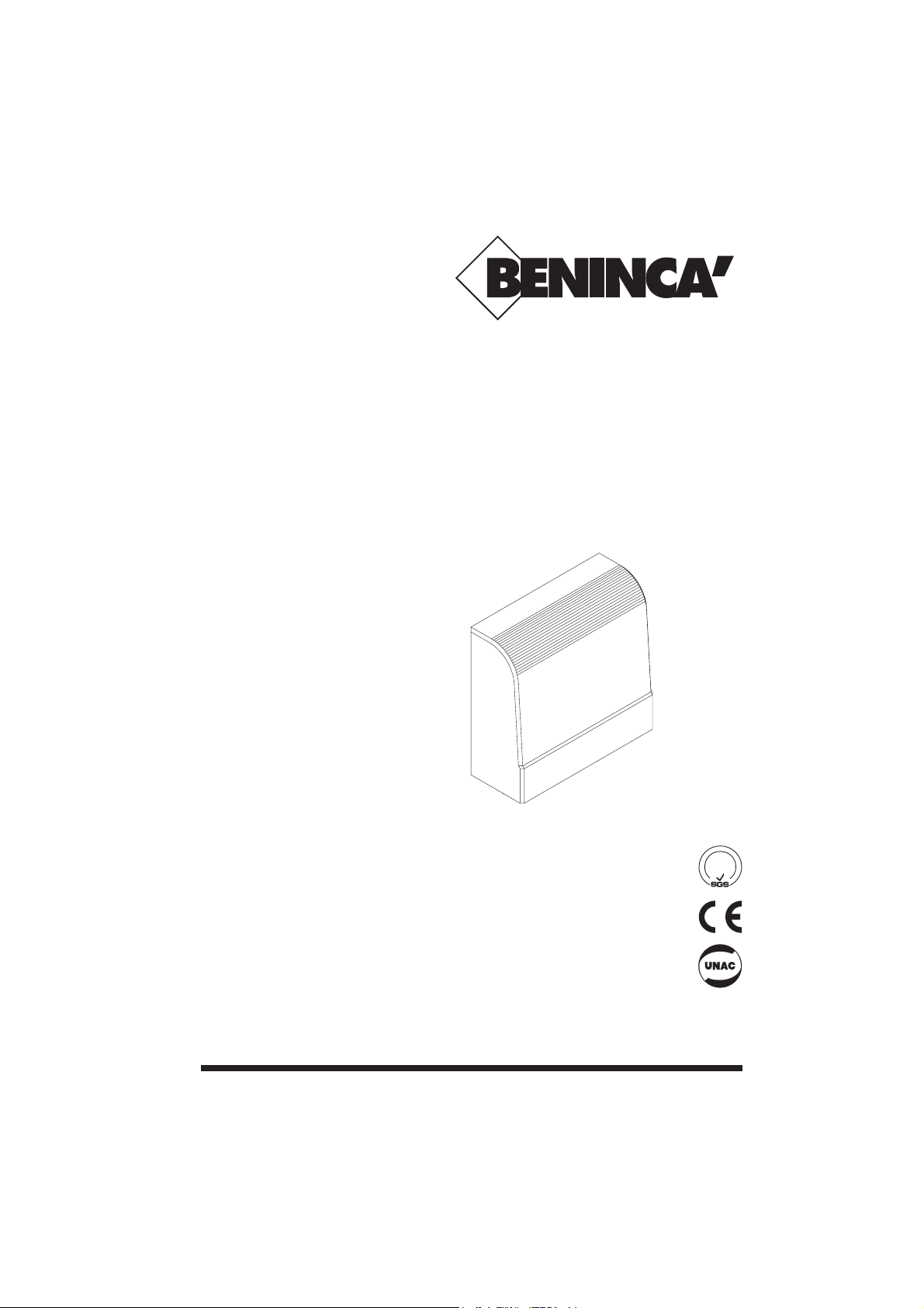
QUADRO DI COMANDO
CONTROL PANEL
SCHALTTAFEL
TABLEAU DE COMMANDE
CUADRO DE CONTROL
AUTOMATISMI PER CANCELLI
®
L8542003
Rev. 02/01/00
Libro istruzioni
Operating instructions
Betriebsanleitung
Livret d’instructions
Libro de instrucciones
UNIONE NAZIONALE COSTRUTTORI
AUTOMATISMI PER CANCELLI, PORTE,
SERRANDE ED AFFINI
A
Z
I
E
N
D
A
C
E
R
T
I
F
I
C
A
T
A
UNI
EN IS O
9001
Page 2
2
Dichiarazione CE di conformità Déclaration CE de conformité
EC declaration of confirmity Declaracion CE de conformidad
EG-Konformitatserklarung
Con la presente dichiariamo che il nostro prodotto
We hereby declare that our product
Hiermit erklaren wir, dass unser Produkt
Nous déclarons par la présente que notre produit
Por la presente declaramos que nuestro producto
DA.B1
è conforme alle seguenti disposizioni pertinenti:
complies with the following relevant provisions:
folgenden einschlagigen Bestimmungen entspricht:
correspond aux dispositions pertinentes suivantes:
satisface las disposiciones pertinentes siguientes:
Direttiva sulla compatibilità elettromagnetica (89/336/
CCE, 93/68/CEE)
EMC guidelines (89/336/EEC, 93/68/EEC)
EMV-Richtlinie (89/336/EWG, 93/68/EWG)
Directive EMV (89/336/CCE, 93/68/CEE) (Compatibilité
électromagnétique)
Reglamento de compatibilidad electromagnética (89/336/
MCE, 93/68/MCE)
Norme armonizzate applicate in particolare:
Applied harmonized standards, in particular:
Angewendete harmonisierte Normen, insbesondere:
Normes harmonisée utilisées, notamment:
Normas armonizadas utilzadas particularmente:
EN 55022, EN 61000-3-2, EN 61000-3-3, EN 50082-1
Norme e specifiche tecniche nazionali applicate in
particolare:
Applied national technical standards and specifications, in
particular:
Angewendete nationale Normen und technische
Spezifikationen, insbesondere:
Normes et specifications techniques nationales qui ont été
utilisées, notamment:
Normas y especificaciones técnicas nacionales que se
utilizaron particularmente:
UNI 8612
Data/Firma
Direttiva sulla bassa tensione (73/23/CEE, 93/68/CEE)
Low voltage guidelines (73/23/EEC, 93/68/EEC)
Tiefe Spannung Richtlinie (73/23/EWG, 93/68/EWG)
Directive bas voltage (73/23/CEE, 93/68/CEE)
Reglamento de bajo Voltaje (73/23/MCE, 93/68/MCE)
Norme armonizzate applicate in particolare:
Applied harmonized standards, in particular:
Angewendete harmonisierte Normen, insbesondere:
Normes harmonisée utilisées, notamment:
Normas armonizadas utilzadas particularmente:
EN 60204-1, EN 60335-1
Data/Firma
AUTOMATISMI PER CANCELLI
®
Automatismi Benincà Srl
Via Scamozzi, 3
36030 MONTECCHIO P. VI
ITALIA
Page 3

3
ANT.
AUT. RECL.
SELECTION
RADIO CONNECTOR
MODE
WORK TIME
FUSE 50mA
FUSE 6.3A
CODE
RX
Phot. Stop Com P.P.
Out 24Vac
(max. 50mA)
230Vac
230V, 40W max.
FCC FCA
AP
CH Com
1 2 3 4 5 6 7 8 9 10
M
11 12 13 14 15
Linea 230Vac
230Vac line
Leitung 230Vac
Ligne 230Vc.a.
Línea 230Vca
Luce di cortesia / autolampeggio (opzionale)
Courtesy light / self-flashing (optional)
Höflichkeitsleuchte / selbstblinkend (Option)
Lumière de courtoisie / autoclignotement (option)
Luz de cortesía / autodestello (opción)
Opzionali
Optionals
Optionen
Options
Opciónes
Page 4

6
DA.B1 Control panel
Functional characteristics
DA.B1 is a single-phase control panel to control the movement of shutters as well as doors and windows. It is provided with a built-in receiver for the remote control of the system, which allows to store
the different transmission codes of max 250 transmitters. The motor start control signal, sent by a radio
control or a step-by-step push button connected to the terminal board, features an operation of the
open-stop-close-stop type. The first impulse controls the opening movement until the work time has
elapsed (or until the opening limit switch, if provided, is triggered). The second impulse controls the
closing movement until the work time has elapsed (or until the opening limit switch, if provided, is
triggered). If an impulse control is given while the motor is turning, the control unit stops the motor and
with the following control impulse the motor starts moving again in the reverse direction.
Automatic closure
If the automatic closure is enabled, as described in the programming of functions, the door or window closes again with no need to send any further control signal after the time already preset by the
installer.
Safety devices
A safety device can be connected (photocell: Normally Closed (N.C.) contact and 24VAC power supply). This device is activated only in the closing phase and causes the complete opening of the door
or window. This input should be short-circuited if not in use.
Installation instructions.
a) The electrical installation and functioning logic must comply with current standards.
b) Keep the power cables (for the motor and power supply) away from the control cables (buttons,
photocells, radio). To avoid interference use two separate sheaths (see EN 60204-1 15.1.3).
c) Check all the connections again before supplying voltage.
d) If the direction of the motor rotation is not correct, invert the ”OPEN” - ”CLOSE” wires of the motor as
well as the wires of the ”FCA” - ”FCC” limit switches.
Input/Output functions
1) Input, antenna
2) Input, antenna earth
3) Input, photocell (NC)
4) Input, stop push button (NC)
5) Input, push buttons common
6) Input, step-by-step push button (Normally Open)
7) Output, photocell power supply, 24Vac, 1.5W
8) Output, photocell power supply, 24Vac, 1.5W
9)
10)
11) Output, closing motor
12) Output, opening motor
13) Output, motor common
14) Input, 230Vac power supply
15) Input, 230Vac power supply
N.B.: the Normally Closed (NC) inputs should be short-circuited if not in use
Programming
SELECTION key: with this key the function to be programmed, which is shown by a flashing LED, is
selected. The chosen function is indicated by a flashing LED which keeps flashing for 20 sec, after
which, if no control signal is sent, the system exits the programming mode.
MODE key: the programming of the selected function is carried out.
The meaning of the various programming LEDs is summarized in the following table:
1) CODE
2) WORK TIME
3) AUT. RECL.
Function / Ref. LED LED off
No code
Minimum time (1 sec.)
Automatic closure disabled
Waiting for the learning code
Work time under
programming
Automatic closure time under
programming
Tx code learned
Work time programmed
Automatic closure enabled for
the preset time
LED flashing LED on
Page 5

7
1) CODE (code learning of the radio controls)
Learning: press SELECTION key until the CODE LED starts flashing and then press the radio control
key.
When the LED light is fixed, the learning is completed.
The learning of the transmitters cannot be carried out when the door or window is moving.
Erasing: press the SELECTION key until the CODE LED starts flashing. Release the SELECTION key
and press the MODE key. All the LEDs switch on and then all codes of the radio controls learned by
the unit are erased (the CODE LED stays off).
2) WORK TIME (programming of the work time from 1 sec to 2 min)
The control panel is supplied with the minimum work time already preset in factory (1 sec, WORK
TIME LED off).
To program the work time: 1) door or window in the closed position, 2) by using the SELECTION key
make the WORK TIME LED flash, 3) release the SELECTION key and press the MODE KEY: the door or
window opens and, when the desired point is reached, stays in this position until the key is released
(the number of the LED flashes allows to count the time in seconds). At this point the work time is
memorized and the WORK TIME LED stays on with fixed light. To modify the work time, repeat the
above procedure.
If an endless work time is required, carry out the procedure by keeping the MODE key pressed for
more than 2 min. In this case, limit switches should be provided to stop the motor.
3) AUT. RECLOSURE (programming of the closing time from 2 sec to 2 min)
The control panel is supplied with the automatic closure disabled.
To program the automatic closure time: 1) by using the SELECTION key, make the AUT. RECL. LED
flash; 2) release the SELECTION key and press the MODE key: at this point, by counting the LED
flashes, it is possible to count the automatic closure time in seconds. When the key is released, the
automatic closure time is stored in memory and the AUT. RECL. LED stays on with fixed light. To
modify the automatic closure time, repeat the above procedure.
To disable the automatic closure, carry out the procedure by keeping the MODE key pressed for less
than 2 sec; when the key is released, the AUT. RECL. LED stays off.
Reset
To reset the control unit to the factory-set configuration, press the SELECTION and MODE keys simultaneously. All LEDs switch on for a while and then stay off. All information stored in memory is
then lost.
Radio diagnosis
The receiver is provided with a LED (RX) for the radio diagnosis through which it is possible to detect
the presence of radio interference which may affect the correct operation of the control unit. The correct
mode is to check between two transmissions:
LED off = no interference;
Flashing LED = slight interference;
LED on = strong interference.
Power supply voltage
Accessories power supply
Output, motor
Operating temperature
Work time
Automatic reclosure time
Receiver frequency
Antenna impedance
Code number
Range
Technical specifications B1 433
Transmitters storable in memory
230Vac +10% -15% - 50Hz
24Vac, 1.5W max.
230Vac, 500W max.
-10 / +60 °C
da 1 a 120 s
da 2 a 120 s
433.92Mhz
50Ω
4096 (fixed code reception)
50 - 150 m
in free space
433.92Mhz
narrow band
50 - 150 m
in free space
30.875Mhz
quartz
50 - 150 m
in free space
306Mhz
super-reactive
50 - 150 m
in free space
250
B1 433 S B1 30 B1 306*
* Device not for EU market
Page 6

AUTOMATISMI PER CA NCELLI
®
AUTOMATISMI BENINCÀ Srl - Via Capitello, 45 - 36066 Sandrigo (VI) - Tel. 0444 751030 r.a. - Fax 0444 759728
 Loading...