

Page 1
Technical Bulletin
Bulletin No: TCH-013-014 Effective Date: 10/27/06 Cancels: N/A Page: 1 of 1
Subject: Bendix
The Bendix® TABS-6 ABS Module uses a locked cover,
similar to some other Bendix ABS units, to protect the
wheel speed sensor and ECU connections from damage,
road spray, grime, etc.
Incorrect installation can lead to the cover being broken or
lost. Please follow the procedure outlined below.
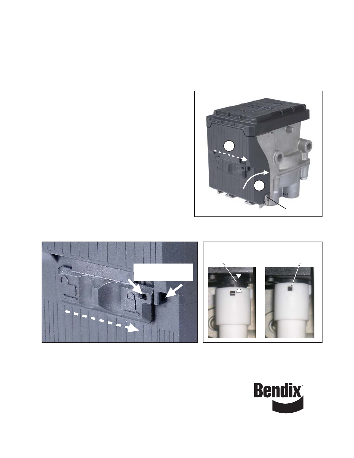
T o install the cover , check to confi rm that all the connectors
are fully installed into position at the top of the housing.
Reinsert the bottom edge of the cover into the hinges and
lean the cover forward into position. Slide the locking tab
to the right to lock it. As an option, a tie-wrap may be used
through the lugs provided.
Note: The cover has internal channels that will prevent
the cover from closing freely if the wheel speed harness
connectors are not fully in position - if resistance is
experienced, check these connections.
Bendix service replacement cover p/n is 802028.
See the Service Data sheet for more information.
®
TABS-6 ABS Module: Cover Installation
2
1
Hinge Point (2)
Figure 1 - Installing the Bendix® TABS-6 ABS Controller Cover
Lugs for Optional
Tie-Wrap Installation
Figure 2 - Locking the Bendix® TABS-6 ABS Controller
Reference Service Data Sheet:
Bendix® TABS-6 Trailer ABS Module . . . . . . SD-13-4767 (BW2469)
ABS Repair and Diagnostics DVD . . . . . . . . . . . . . . . . . . . .BW2538
Visit the Literature Center on www.bendix.com for free downloads of
Service Data sheets or to order copies.
Shows
Connector Not
Fully Seated
Figure 3 - Harness Connector Position
Shows Connector Fully
Seated in Correct Position.
Note: Tab Installs in Slot
©2006 Bendix Commercial Vehicle Systems LLC 10/06. All Rights Reserved. Printed in U.S.A.
 Loading...