

Page 1
®
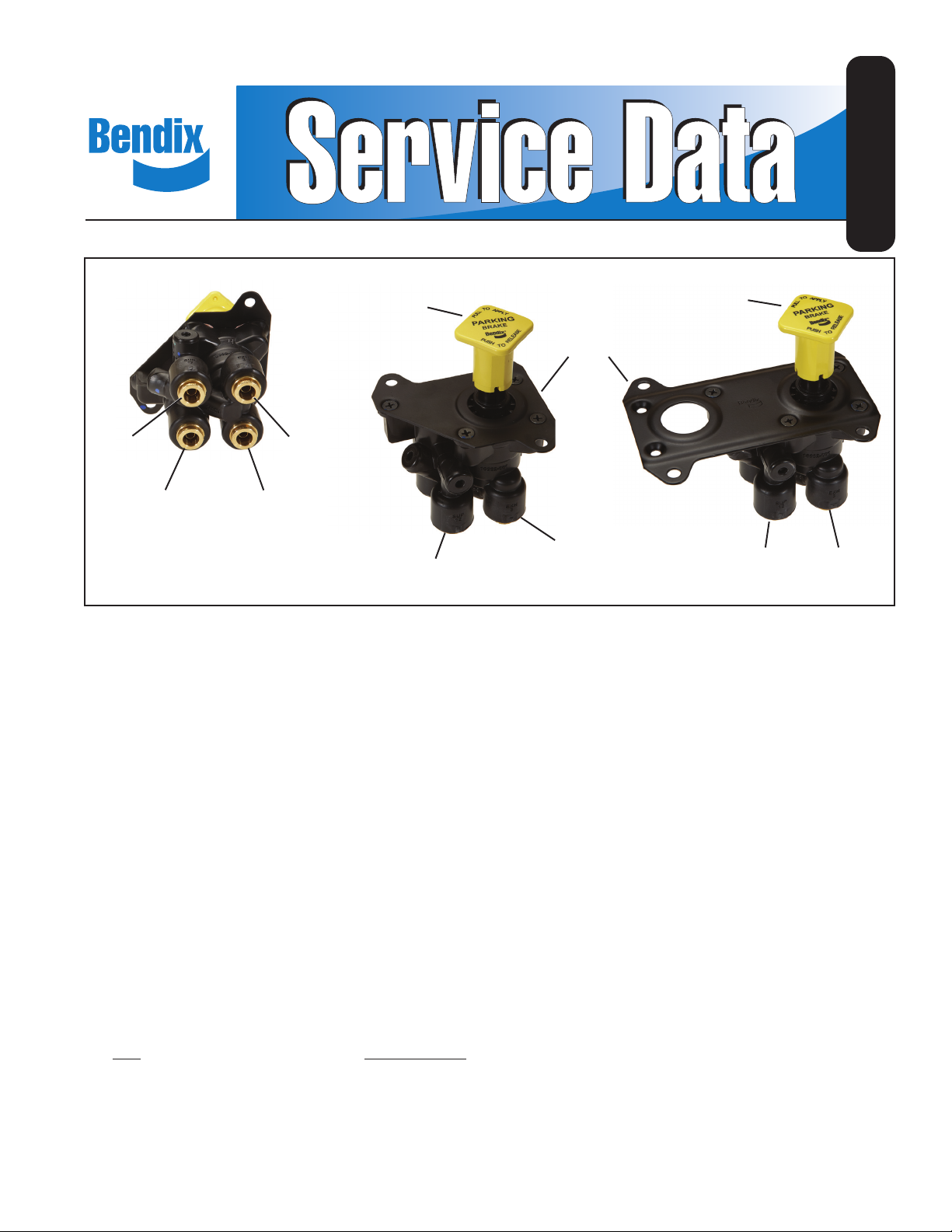
Bendix® PP-DC® Park Control Valve
SD-03-3619
BUTTON
SUPPLY
12
SUPPLY
11
FIGURE 1 - BENDIX® PP-DC® PARK CONTROL VALVE
EXHAUST
3
DELIVERY
21
SUPPLY
12
DESCRIPTION
The Bendix® PP-DC® park control valve is a push-pull,
manually operable on/off valve. It is dash board-mounted
and provides in-cab control of truck or bus parking brakes.
The valve is pressure sensitive—it automatically
moves from the applied to the exhaust position when
total system pressure drops below 20 to 40 psi. (Note
that this is a Bendix
mandated requirement. Refer to Bendix Technical
Bulletin TCH-003-051). Also, manually pulling the
button will apply the parking brakes.
The PP-DC valve body is made of non-metallic, noncorrosive material, and the cover is available in several
variations (see Figure 1). The valve is designed to accept
pipe thread fi ttings or push-to-connect fi ttings that use SAE
J844 non-metallic air brake tubing.
Ports:
Port Embossed I.D.
Primary Reservoir Supply SUP 11
Secondary Reservoir Supply SUP 12
Delivery DEL 21
Exhaust EXH 3
®
product specification and not a
BUTTON
COVER
EXHAUST
3
SUPPLY
12
EXHAUST
3
OPERATION
GENERAL
The PP-DC valve receives its supply of air from the primary
service reservoir or the secondary service reservoir,
whichever is at the higher pressure. When the button
is pushed in, the valve delivers air to the spring brake
chambers (usually through a spring brake valve such as
the Bendix
valve). The air releases the spring brakes for normal vehicle
operation.
To apply the parking brakes, the button is pulled out, which
exhausts the PP-DC valve delivery and releases air from
the spring brake chambers.
When total system pressure drops below 20 to 40 psi,
the valve will automatically “pop out,” which removes the
hold-off air in the chambers and applies the spring brakes.
PARKING BRAKES RELEASED
To release the parking brakes, the push-pull button is
pushed in. The PP-DC valve plunger moves, closing the
exhaust port with the exhaust seal and allowing the plunger
o-ring to move past the guide spool. Supply air then travels
out the delivery port to release the brakes.
®
SR-7® valve and a relay, or quick release,
1
Page 2
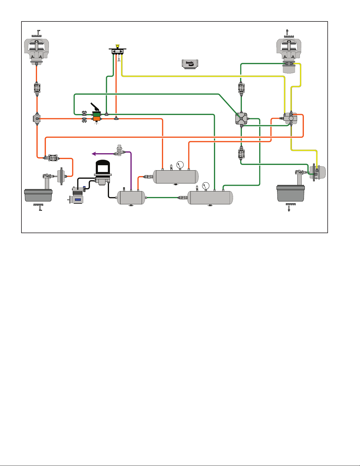
Bendix®
ADB-22X
Disc Brake
Antilock
Modulator
(4 places)
Quick Release
Valve
™
Brake Valve
To Accessories
Air Dryer
®
Bendix
PP-DC®
Park Control
Valve
®
Bendix
PR-3™/ PR-4™
Valve
Bendix
EC-60
Controller
Front
Axle Reservoir
®
™
Electronic
Disc Brake
Service
Relay
Valve
ADB-22X
™
®
Bendix
®
SR-7
Spring Brake
Modulating
Valve
Supply
Reservoir
Air Compressor
Air disc & drum brake actuation combined on a single axle are shown for pictorial purposes only.
FIGURE 2 - TYPICAL 4 X 2 TRUCK SCHEMATIC WITH BENDIX
Note that Figure 3 shows the primary service reservoir
supplying the Bendix
®
PP-DC® valve. The double check
valve diaphragm has sealed the secondary reservoir supply
port and allows air to pass from the primary reservoir into
the PP-DC valve.
If primary service reservoir pressure drops below secondary
service reservoir pressure, the double check valve reacts
as shown in Figure 4. It seals the primary service reservoir
supply port and supplies the Bendix PP-DC park control
valve with air from the secondary service reservoir. The
push-pull button remains in and the spring brakes remain
released.
PARKING BRAKES APPLIED
Figure 5 shows the PP-DC valve in the parking-brakesapplied position. This will occur when the driver manually
pulls out the push-pull button, or when the total system
pressure drops to below 20 to 40 psi.
As shown in Figure 6, when the button “pops” out, the
exhaust seal moves to open the exhaust port to the
atmosphere, allowing delivery line pressure to exhaust.
The plunger o-ring moves to seal off supply pressure.
Spring brake hold-off air is exhausted through the spring
brake relay valve.
Rear
Axle Reservoir
®
PP-DC® PARK CONTROL VALVE
PREVENTIVE MAINTENANCE
Important: Review the Bendix Warranty Policy before
performing any intrusive maintenance procedures. A
warranty may be voided if intrusive maintenance is
performed during the warranty period.
No two vehicles operate under identical conditions; as
a result, maintenance intervals may vary. Experience is
a valuable guide in determining the best maintenance
interval for air brake system components. At a minimum, the
PP-DC valve should be inspected every six (6) months or
1500 operating hours, whichever comes fi rst, for proper
operation. Should the PP-DC valve not meet the elements
of the Operational Tests noted in this document, further
investigation and service of the valve may be required.
SERVICE CHECKS
1. Remove any accumulated contaminants. Visually
inspect the valve’s exterior for excessive wear or
physical damage. Repair/replace as nec essary.
2. Inspect all air lines connected to the valve for signs of
wear or physical damage. Repair/replace as necessary.
3. Test air line fi ttings for excessive leakage. Repair or
replace as necessary.
2
Page 3

PRIMARY
SUPPLY
SECONDARY
SUPPLY
EXHAUST DELIVERY
PRIMARY
SUPPLY
SECONDARY
SUPPLY
EXHAUST DELIVERY
FIGURE 3 - PARK BRAKE RELEASED (Primary Reservoir
Supply)
FIGURE 5 - PARK BRAKE APPLIED
PRIMARY
SUPPLY
FIGURE 4 - PARK BRAKE RELEASED (Secondary Reservoir
Supply)
SECONDARY
SUPPLY
EXHAUST
DELIVERY
PRIMARY
SUPPLY
FIGURE 6 - PARK BRAKE EXHAUST
SECONDARY
SUPPLY
EXHAUST DELIVERY
3
Page 4

LEAKAGE AND OPERATIONAL TESTS
To perform the tests that follow, connect two separate
120 psi air sources to the Bendix® PP-DC® valve supply
ports. Tee an accurate test gauge into the supply lines,
and provide for a means to control supply line pressure.
Connect a small volume with a gauge to the delivery port.
LEAKAGE TEST
1. Supply the valve with 120 psi from the primary reservoir
supply port. With the button out, coat the exhaust port
and the plunger stem with a soap solution. Leakage
should not exceed a 1” bubble in fi ve (5) seconds. There
should be no leakage from the secondary reservoir
supply port.
2. With the button out, supply the valve with 120 psi from
the secondary reservoir supply port. There should be
no leakage from the primary reservoir supply port.
3. With the button in, coat the exhaust port and the plunger
stem with a soap solution. Leakage at both areas should
not exceed a 1” bubble in three (3) seconds.
OPERATIONAL TEST
1. With the button out, supply either supply port with
120 psi of air. Then push the button in. Air pres sure
should rise in the delivery volume equivalent to supply
pressure.
2. Pull the button out. Delivery pressure should exhaust
to 0 psi.
3. Build each supply source to 120 psi. Decrease supply
pressure at the secondary service reservoir supply port
at a rate of 10 psi per second. Primary supply pressure
and delivery pressure should not drop below 100 psi.
Repeat the test for decreasing primary service reservoir
pressure.
4. Build each supply source to 120 psi. Then decrease
both supply pressures to below 20–40 psi. The button
should automatically “pop” out when pressure drops
within that range.
If the PP-DC park control valve fails to function as
described, or if leakage is excessive, repair the valve or
replace it at the nearest authorized Bendix
®
parts outlet.
REMOVAL
1. Identify and mark or label all air lines and their
connections on the valve.
2. Remove the PP-DC valve from the vehicle and save
the mounting hardware.
INSTALLATION
1. Install the Bendix PP-DC valve in its location on the
dashboard. Using the mounting hardware saved in
“REMOVAL,” secure the valve to the vehicle.
2. Reconnect all air lines to the valve using the
identifi cation made in “REMOVAL.”
3. Perform “LEAKAGE AND OPERATIONAL TESTS”
before placing the vehicle back in service.
DISASSEMBLY
The disassembly and assembly procedures that follow
are for reference only. Always have the appropriate
maintenance kit on hand and use its instructions in lieu
of those presented here. Refer to Figure 7 throughout the
procedure.
1. Turn the button counterclockwise to remove it from the
plunger stem.
2. Remove the four screws that secure the cover to the
body, and remove the cover.
3. Pull the plunger stem to remove the plunger and the
guide spool from the body.
4. Remove plunger spring(6) and discard.
5. If necessary, use a screwdriver to carefully remove the
check valve seat from the body. Be sure not to damage
the check valve seat or the body.
6. Remove and discard check valve seat o-rings(7)
and (8).
7. Turn the body upside down and gently tap it on a fl at
surface to remove check valve(9). Discard the check
valve.
8. Remove the guide spool from the plunger. Remove and
discard o-ring(1) from the guide spool.
9. Remove and discard o-rings(2), (3) and (5) from the
plunger. Also remove and discard exhaust seal(4).
CLEANING & INSPECTION
1. Wash all metal parts in mineral spirits and thoroughly
dry.
2. Inspect all re-usable parts for excessive wear or
damage. Inspect the body for gouges or deep scuffi ng.
Replace key numbers 1-9 (and any parts not determined
usable) with genuine Bendix
®
replacements.
ASSEMBLY
Before assembly, lubricate all o-rings, o-ring grooves,
rubbing surfaces and bores with Bendix silicone lubricant
(Bendix piece number 291126) or equivalent.
1. Place check valve(9) into its seat in the body with its
fl at surface facing upward. If necessary, reach into the
body to make sure the valve is seated evenly in the
bore.
2. Install o-rings(7) and (8) on the check valve seat and
install the check valve seat into the body. Make sure
the seat is fully seated—its surface should be even with
the body’s surface.
3. Install plunger spring(6) into the body. Make sure it
stands upright and is seated properly in the body bore.
(It should surround the protrusion or “lip” at the bottom
of the body bore.)
4. Install o-rings(2), (3), (5) and exhaust seal(4) onto the
plunger. Then install the plunger into the body. Line up
the plunger’s index tabs with the spaces in the body
bore for ease of installation.
4
Page 5

BUTTON
COVER
1
GUIDE
SPOOL
SCREW
2
3
PLUNGER
STEM
CHECK VALVE SEAT
PLUNGER
INDEX TABS
4
5
6
BODY
7
8
9
FIGURE 7 - EXPLODED VIEW
5
Page 6

5. Install o-ring(1) onto the guide spool. Then install the
guide spool over the plunger and into the body. Press
the guide spool into place fi rmly.
6. Place the cover onto the body and secure with its four
screws. Torque to 35 in. lbs.
7. Thread the button clockwise onto the plunger stem.
It should take approximately three (3) full button
revolutions to install it on the plunger. The protrusions
on the side of the plunger should line up with the button
grooves. Push on the button a number of times to make
sure the plunger moves freely throughout its range of
motion.
NOTE: BEFORE PLACING THE VEHICLE BACK
INTO SERVICE, PERFORM THE “LEAKAGE AND
OPERATIONAL TESTS” IN THIS DOCUMENT.
6
SD-03-3619_US_006 © 2013 Bendix Commercial Vehicle Systems LLC, a member of the Knorr-Bremse Group. All Rights Reserved.
 Loading...