

Page 1
Bendix Brake Chambers
SD-02-1302
Different size brake chambers are identified by numbers
which specify the effective area of the diaphragm. A type
30 brake chamber has 30 square inches effective area.
Since one side of a brake chamber diaphragm is exposed
to the applying air pressure and the other side to atmospheric
pressure, the chamber has a pressure and a non-pressure
side. The non-pressure plate is usually vented to atmosphere
with four holes, however, on those inst allations where the
chamber must be weather-proof, venting is accomplished
through a drilled passage in the mounting bolts and the rod
opening in the non-pressure plate is sealed by either a
boot or an o-ring seal.
The standard diaphragm material is a compound of natural
rubber with a fabric interior of nylon. Neoprene-nylon
diaphragms are optionally available.
DESCRIPTION
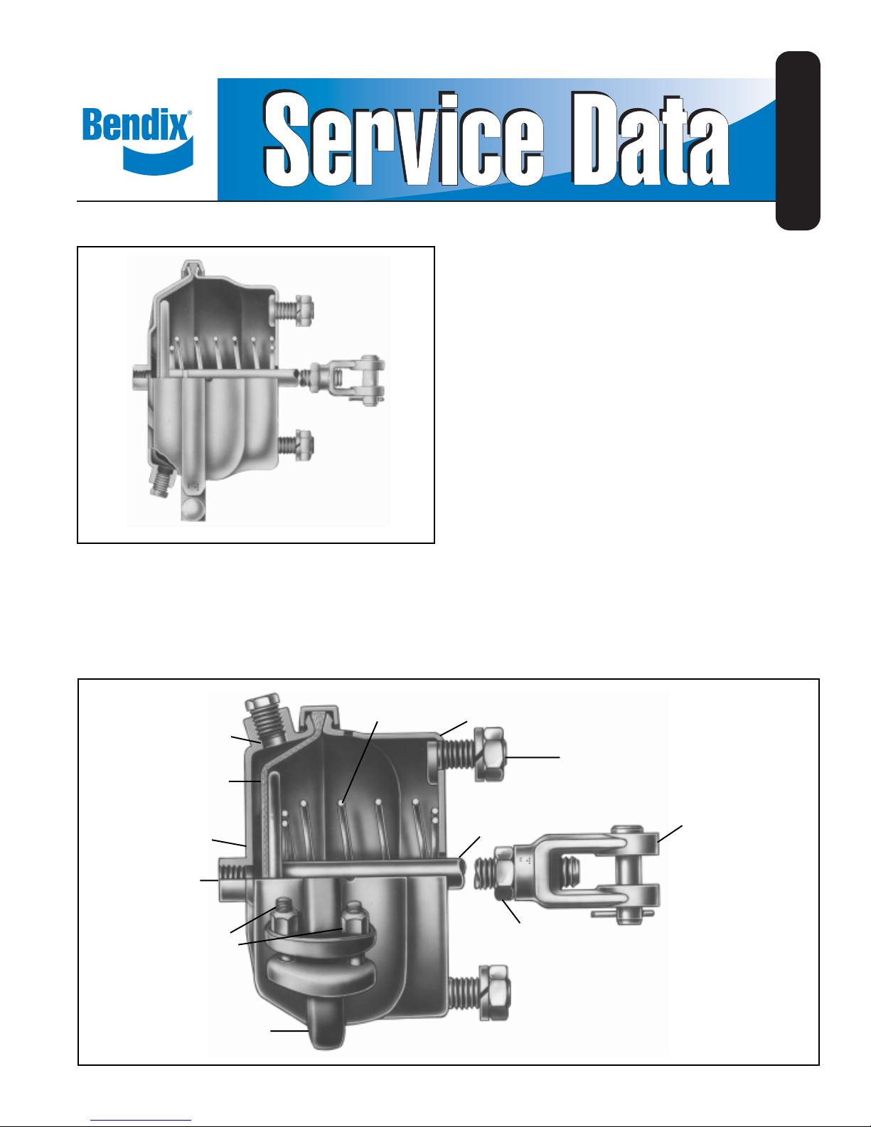
The brake chamber is a diaphragm type actuator which
converts the energy of air pressure into mechanical force.
The diaphragm is held between the pressure plate and nonpressure plate by either a one piece clamp ring or a two
piece clamp ring (Figs. 1 and 2).
SPRING
INLET PORT
DIAPHRAGM
PRESSURE PLATE
INLET PORT
CLAMP RING
NUTS & BOLTS
Smaller chambers such as type 3 and type 6 have one 1/4
in. NPT inlet port in the center of the pressure plate. Larger
size chambers may have a center port and a side located
port or either one. Current production Type 20 chambers
and larger, generally have 3/8 in. NPT ports to facilitate
compliance with FMVSS 121.
NON
PRESSURE
PLATE
MOUNTING
BOLTS
PUSH ROD
ASSY.
LOCK NUT
YOKE
CLAMP RING
1
Page 2

OPERATION
Controlled air pressure enters the brake chamber through
the inlet port and acts upon the diaphragm moving the push
plate and rod assembly forward.
When the brake chamber is used to actuate cam type brake
foundation assemblies, the yoke (which is threaded on the
push rod) is connected to a slack adjuster, which in turn is
connected to the brake cam shaft. This forward motion of
the push rod rotates the slack adjuster , cam shaft and cam
applying the vehicle brakes.
The greater air pressure admitted to the brake chamber, the
greater the force applied by the push rod and conversely,
the less pressure applied to the brake chamber the less
force applied by the push rod. Push rod force is determined
by multiplying the delivered air pressure by the effective
diaphragm area. For example, if 60 psi is admitted to a type
30 brake chamber, the lineal force on the end of the push
rod is approximately 1800 lbs.
CLAMP RING TYPE BRAKE CHAMBER DA T A
(Dimensions in Inches)
Max. Max. Stroke
Stroke at Which
Effective * With Brakes
Area Outside Max. Brakes Should Be
Type (Sq. In.) Diameter Stroke Adjusted Readjusted
6 6 4-1/2 1-5/8 Should 1-1/4
9 9 5-1/4 1-3/4 be as 1-3/8
12 12 5-1 1/16 1-3/4 short as 1-3/8
16 16 6-3/8 2-1/4 possible 1-3/4
20 20 6-25/32 2-1/4 without 1-3/4
24 24 7-7/32 2-1/4 brakes 1-3/4
30 30 8-3/32 2-1/2 dragging 2
36 36 * * 2-1/4
*Dimensions listed do not include capscrew head
projections for rotochambers and bolt projections for
clamp type brake chambers.
FIGURE 3
When air pressure is released from the brake chamber, the
push rod return spring in combination with the brake shoe
return spring returns the diaphragm, push plate and rod
assembly, slack adjuster and brake cam to their released
positions releasing the brakes.
PREVENTIVE MAINTENANCE
A. Every Month, 8,000 Miles or 300 Operating Hours,
depending on type of operation
1. Check push rod travel and adjust travel at the slack
adjuster if needed. Push rod travel should be as short
as possible without brakes dragging. Excessive push
rod travel reduces braking efficiency, shortens
diaphragm life, gives slow braking response and
wastes air.
2. Check push rod to slack adjuster alignment from
release to full stroke position to be sure push rod
moves out and returns properly without binding at
the non-pressure plate hole or with other structures.
Also check the angle formed by the slack adjuster
arm and push rod. It should be greater than 900 when
the chamber is in the released position and approach
900 at maximum re-adjustment stroke.
3. Check tightness of mounting nuts. Check cotter pins
to make sure they are in place.
4. Check all hoses and lines. They should be secure
and in good condition.
B. Every Year or after each 100,000 Miles or 3600 Operating
Hours, depending on type of operation
1. Disassemble and clean all parts.
2. Install new diaphragm or any other parts if they are
worn or deteriorated. When the diaphragm, spring,
or both are replaced, they should be replaced in the
corresponding chamber on the same axle.
OPERATING AND LEAKAGE TESTS
A. OPERATING TEST
1. Apply brakes and observe the push rods move out
promptly and without binding.
2. Release brakes and observe that the push rods return
to the released position promptly and without binding.
3. Check push rod travel. Push rod travel should be as
short as possible without brakes dragging. Adjust
travel of push rod at slack adjuster if necessary .
B. LEAKAGE TEST
1. Make and hold a full brake application.
2. Using soap solution, coat clamping ring(s). If leakage
is detected, tighten clamping ring only enough to
stop leakage. DO NOT OVERTIGHTEN as this can
distort sealing surface or clamping ring. Coat area
around push rod hole (loosen boot if necessary). No
leakage is permitted. If leakage is detected, the
diaphragm must be replaced.
REMOVING AND INSTALLING
A. REMOVING
1. Block vehicle wheels.
2. Release air pressure in all reservoirs.
3. Disconnect line to chamber .
4. Remove the yoke pin.
5. Remove the brake chamber .
2
Page 3

B. INST ALLING
1. Mount brake chamber to mounting bracket.
2. Install yoke (if removed) and yoke pin.
3. Check the angle formed by the centerline of the push
rod and slack adjuster. This angle should be greater
than 90° in the released position and approach 90°
at maximum readjustment stroke.
4. Connect line to chamber. Check to be sure hoses
are properly supported and clamped if necessary to
provide proper clearance.
DISASSEMBLY
Clean exterior of brake chamber and mark parts in relation
to position to each other so that it may be assembled in the
same way .
NOTE: If brake chamber is to be dismantled without
removing non-pressure plate from vehicle, slack
adjuster should be backed-off.
CLAMP RING TYPE CHAMBER
1. Pull out (or push out with air pressure) push rod and
clamp it at non-pressure plate. If using vise grip pliers,
push rod should be protected so that it will not be
damaged.
2. Remove clamp ring nuts and bolts.
3. If chamber has single clamp ring, spread the ring slightly,
just enough to slip it off the plate. Care should be used
so that clamp ring is not distorted. If chamber uses two
piece clamp ring, remove clamp rings.
4. Remove pressure plate and diaphragm.
5. Remove yoke lock nut and yoke from push rod and
release grip on push rod being careful to contain the
push plate and non-pressure plate until the return spring
load is relaxed.
6. Remove push rod assembly and spring.
7. Remove boot or o-ring (if applicable).
CLEANING AND INSPECTION
1. Clean all metal parts in cleaning solvent, removing all
rust and scale. All diaphragm sealing surfaces should
be smooth and clean.
2. Carefully inspect all metal parts for cracks, distortion or
damage.
3. Replace all rubber parts and all other parts not
considered serviceable with genuine Bendix replacement
parts.
ASSEMBLY
CLAMP RING TYPE CHAMBER
1. Stand push rod assembly upright on a flat surface.
2. Position return spring on push rod.
3. Install boot or o-ring on non-pressure plate (if applicable).
4. Position non-pressure plate on push rod, and press plate
down against tension of spring until plate bottoms on
flat surface. Clamp rod with vise grips (protect rod) at
the plate.
5. If installing single clamp ring, position ring over clamping
surface of non-pressure plate.
6. Check alignment marks (made before disassembly) and
position diaphragm in pressure plate and place on
nonpressure plate.
7. If installing single clamp ring, work the clamp ring over
the clamping surface of the pressure plate and draw
the clamp lugs together with vise grips or a similar tool.
Install bolt and nut in clamp and tighten, tapping with a
soft faced mallet to center the clamp ring if necessary .
Release grip on push rod and install remaining bolt and
nut.
8. Install nuts and bolts evenly and only sufficiently to
eliminate leakage.
TESTING OF A REBUIL T BRAKE CHAMBER
Perform tests outlined in “Operating and Leakage Tests”
section.
GENERAL SAFETY GUIDELINES
WARNING! PLEASE READ AND FOLLOW
THESE INSTRUCTIONS TO AVOID
PERSONAL INJURY OR DEATH:
When working on or around a vehicle, the
following general precautions should be
observed
1. Park the vehicle on a level surface, apply the
parking brakes, and always block the wheels.
Always wear safety glasses.
2. Stop the engine and remove ignition key when
working under or around the vehicle. When
working in the engine compartment, the engine
should be shut off and the ignition key should be
removed. Where circumstances require that the
engine be in operation, EXTREME CAUTION should
be used to prevent personal injury resulting from
contact with moving, rotating, leaking, heated or
electrically charged components.
3. Do not attempt to install, remove, disassemble or
assemble a component until you have read and
thoroughly understand the recommended
procedures. Use only the proper tools and observe
all precautions pertaining to use of those tools.
at all times.
3
Page 4

4. If the work is being performed on the vehicle’s air
brake system, or any auxiliary pressurized air
systems, make certain to drain the air pressure
from all reservoirs before beginning ANY work on
the vehicle. If the vehicle is equipped with an
®
AD-IS
air dryer system or a dryer reservoir
module, be sure to drain the purge reservoir.
5. Following the vehicle manufacturer’s
recommended procedures, deactivate the
electrical system in a manner that safely removes
all electrical power from the vehicle.
8. Use only genuine Bendix
®
replacement parts,
components and kits. Replacement hardware,
tubing, hose, fittings, etc. must be of equivalent
size, type and strength as original equipment and
be designed specifically for such applications and
systems.
9. Components with stripped threads or damaged
parts should be replaced rather than repaired. Do
not attempt repairs requiring machining or welding
unless specifically stated and approved by the
vehicle and component manufacturer.
6. Never exceed manufacturer’s recommended
pressures.
7. Never connect or disconnect a hose or line
containing pressure; it may whip. Never remove a
component or plug unless you are certain all
system pressure has been depleted.
10. Prior to returning the vehicle to service, make
certain all components and systems are restored
to their proper operating condition.
11. For vehicles with Antilock Traction Control (ATC),
the ATC function must be disabled (ATC indicator
lamp should be ON) prior to performing any vehicle
maintenance where one or more wheels on a
drive axle are lifted off the ground and moving.
4
BW1426 © 2007 Bendix Commercial Vehicle Systems LLC. All rights reserved. 3/2007 Printed in U.S.A.
 Loading...