

Page 1
®
Bendix® PP-1™, PP-2™, PP-5™, PP-8™, & RD-3™ Push-Pull Type
Control Valves
SD-03-3611
™
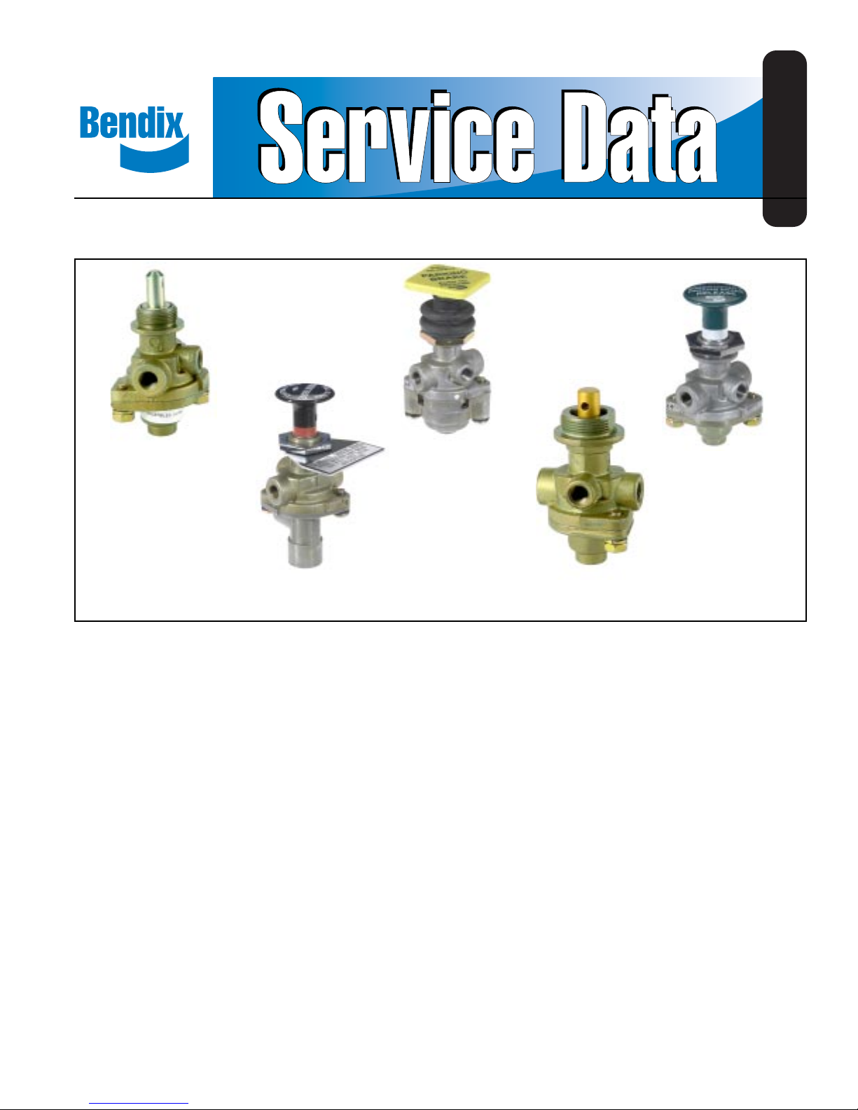
PP-1
VALVE
™
PP-2
VALVE
FIGURE 1 - PUSH-PULL TYPE CONTROL VALVES
DESCRIPTION
The PP valves are push-pull manually operable on-off air
control valves with an exhaust function. Most are pressure
sensitive, so that they will automatically move from the
applied to the exhaust position as supply pressure is
reduced to a certain minimum, depending on the spring installed. The exception to this is the PP-8™ valve and some
PP-1™ valves which have no spring. The PP-8™ valve also
has a larger diameter shaft for button mounting so that when
installed on the same panel with other PP valves the
buttons cannot be inadvertently mixed. The PP-8™ valve is
normally used to operate tractor spring brakes independently
from the trailer.
The PP-5™ valve is unique in having an auxiliary piston in
the lower cover which, upon receiving a pneumatic signal of
18 psi or more, will cause the valve to move from the applied
to the exhaust position from a 100 psi application.
The RD-3™ valve differs slightly in that it normally remains in
the exhaust position and requires a constant manual force
to hold it in the applied position.
™
PP-5
VALVE
PP-8
VALVE
™
RD-3
VALVE
™
The PP-2™ valve has an auxiliary port which may be plumbed
into a service brake line to release the spring brakes if a
service application is made, preventing compounding of
forces on the foundation brakes.
PREVENTIVE MAINTENANCE
Important: Review the Bendix Warranty Policy before per-
forming any intrusive maintenance procedures. A warranty
may be voided if intrusive maintenance is performed during
the warranty period.
No two vehicles operate under identical conditions, as a
result, maintenance intervals may vary . Experience is a valuable guide in determining the best maintenance interval for
air brake system components. At a minimum, the PP valves
should be inspected every 6 months or 1500 operating hours,
whichever comes first, for proper operation. Should the PP
valves not meet the elements of the operational tests noted
in this document, further investigation and service of the
valve may be required.
1
Page 2

AUTOMATIC MOMENTARY PILOT TRIP NON-
EXHAUST APPLY FEATURE AUTOMATIC
PP-1 20,30,40
or 60 psi
PP-2 40 psi
PP-5 40 psi 18 psi
RD-3 Must be held
PP-8 Will remain in
manually
either position
REMOVAL
Block and/or hold the vehicle by a means other than air
brakes and drain all reservoirs.
1. Drive the button roll-pin out with a punch and remove the
button.
2. Mark each air supply line and its port for easy reinstallation, then disconnect them. Remove the valve from the
panel by removing the panel mounting nut.
INSTALLING
1. Install valve in panel, securing with the panel mounting
nut.
2. Reconnect the air lines using marks made during removal
as a guide.
3. Install the operating button. Secure the operating button
by installing the button roll pin.
DISASSEMBLY: PP-1™, PP-8™ AND RD-3
™
VALVES
1. Remove the two cap screws (3) which retain the lower
cover and remove cover. Remove the sealing ring (4).
2. Insert a small punch through the roll pin hole in the stem
and remove the lock nut (5).
3. Remove inlet-exhaust valve (6) and plunger (7) and spring
(8) (if any).
4. Remove o-ring (9) from plunger.
DISASSEMBLY: PP-5™ VALVE
1. Perform same operations as for PP-1™ valve.
2. Remove inlet seal (10) in Figure 4 from lower cover.
Remove the ring diaphragm (4) from the inlet seat.
3. Remove piston (11) Figure 4 and o-ring (2).
DISASSEMBLY: PP-2™ VA LVE
1. Insert a small punch through the roll pin hole in the plunger
and remove the lock nut (1) from the plunger.
2. Withdraw the plunger and remove the spring (9) and
o-ring (8).
3. Remove the two machine screws (2) and remove the
lower cover (3).
4. Remove the inlet-exhaust valve (4), and piston (5).
5. Remove o-rings (6 & 7) from piston.
OPERATING AND LEAKAGE TESTS
PP-1™, PP-8™, RD-3™ VA LV E
1. An accurate test gauge should be tee’d into the supply
line and a means of controlling the supply pressure provided. Apply a 120 psi air source to the supply port. A
small volume reservoir (e.g. 90 cu. in.) with a gauge
should be connected to the delivery port.
2. With 120 psi supply pressure, and the button pulled out
(exhaust position), leakage at the exhaust port should
not exceed a 1" bubble in 5 seconds; at the plunger
stem a 1" bubble in 5 seconds. There should be no leakage between upper and lower body.
3. Push the button in (applied position). Leakage at the exhaust port should not exceed a 1" bubble in 3 seconds; at
the plunger a 1" bubble in 3 seconds. (The RD-3™ valve
will have to be manually held in this position.)
4. Reduce the supply pressure. At a pressure from 60 to
20 psi depending on the spring installed the button should
pop out automatically , exhausting the delivery volume.
(This does not apply to the RD-3™, PP-8™ or some
PP-1™ valve’s).
PP-5™ VALVE
1. Proceed as for PP-1™ valve through Step 3.
2. Connect a modulated source of air pressure to the pilot
air inlet. With the button pushed in (applied position)
with 125 psi supply pressure and a gradually increasing
pressure applied at the pilot air port the valve should
move to the release position with a pilot pressure of not
more than 18 psi. Leakage in this mode should not
exceed a 1" bubble in 3 seconds at the exhaust port
and a 1" bubble in 5 seconds at the plunger stem.
PP-2™ VALVE
1. Proceed as for PP-1™ valve through Step 1.
2. With the button pulled out (exhaust position), leakage
at the brake valve port or at the plunger stem should not
exceed a 1" bubble in 5 seconds.
3. Push the button in. Supply pressure should be present
in the delivery volume. Leakage at the exhaust port or
around the plunger stem should not exceed a 1" bubble
in 5 seconds.
4. Pull the button out and apply supply pressure at the
brake valve port. Supply pressure should be present in
the delivery volume and leakage at the exhaust port
should not exceed a 1" bubble in 5 seconds.
Note: If any of the above push-pull valves do not function as
described or if leakage is excessive, it is recommended
they be returned to our nearest authorized distributor for a
factory rebuilt or new valve.
2
Page 3

PANEL
MOUNTING
NUT
BUTTON ROLL
PIN
PANEL
MOUNTING
NUT
BUTTON ROLL
PIN
9
8
6
5
™
PP-1
7
4
3
BRAKE
VALVE
PORT
VALVE
FIGURE 2 FIGURE 3
PANEL
MOUNTING
NUT
9
9
4
5
1
PP-2
™
8
2
3
6
7
VALVE
9
11
7
8
6
10
5
4
6
7
4
3
5
™
PP-8
VALVE
™
PP-5
VALVE
3
2
FIGURE 5FIGURE 4
3
Page 4

GENERAL SAFETY GUIDELINES
WARNING! PLEASE READ AND FOLLOW
THESE INSTRUCTIONS TO AVOID
PERSONAL INJURY OR DEATH:
When working on or around a vehicle, the
following general precautions should be
observed
1. Park the vehicle on a level surface, apply the
parking brakes, and always block the wheels.
Always wear safety glasses.
2. Stop the engine and remove ignition key when
working under or around the vehicle. When
working in the engine compartment, the engine
should be shut off and the ignition key should be
removed. Where circumstances require that the
engine be in operation, EXTREME CAUTION should
be used to prevent personal injury resulting from
contact with moving, rotating, leaking, heated or
electrically charged components.
3. Do not attempt to install, remove, disassemble or
assemble a component until you have read and
thoroughly understand the recommended
procedures. Use only the proper tools and observe
all precautions pertaining to use of those tools.
4. If the work is being performed on the vehicle’s air
brake system, or any auxiliary pressurized air
systems, make certain to drain the air pressure from
all reservoirs before beginning ANY work on the
vehicle. If the vehicle is equipped with an AD-IS
air dryer system or a dryer reservoir module, be
sure to drain the purge reservoir.
5. Following the vehicle manufacturer’s
recommended procedures, deactivate the electrical
system in a manner that safely removes all
electrical power from the vehicle.
at all times.
PANEL
MOUNTING
NUT
6
5
RD-3
BUTTON ROLL
PIN
3
™
VALVE
FIGURE 6
8. Use only genuine Bendix® replacement parts,
components and kits. Replacement hardware,
tubing, hose, fittings, etc. must be of equivalent
size, type and strength as original equipment and
be designed specifically for such applications and
systems.
9. Components with stripped threads or damaged
®
parts should be replaced rather than repaired. Do
not attempt repairs requiring machining or welding
unless specifically stated and approved by the
vehicle and component manufacturer.
10. Prior to returning the vehicle to service, make
certain all components and systems are restored
to their proper operating condition.
9
7
8
4
6. Never exceed manufacturer’s recommended
pressures.
7. Never connect or disconnect a hose or line
containing pressure; it may whip. Never remove a
component or plug unless you are certain all
system pressure has been depleted.
4
BW1578 © 2006 Bendix Commercial Vehicle Systems LLC. All rights reserved. 7/2006 Printed in U.S.A.
11. For vehicles with Antilock Traction Control (ATC),
the ATC function must be disabled (ATC indicator
lamp should be ON) prior to performing any vehicle
maintenance where one or more wheels on a drive
axle are lifted off the ground and moving.on a drive
axle are lifted off the ground and moving.
 Loading...