


BEKOMAT 33U
EN - english
Instructions for installation and operation
Condensate drain
BEKOMAT®33U / 33U CO (BM33U / BM33UCO)
01-1619

2 BEKOMAT® 33U / 33U CO
Dear customer,
Thank you for deciding in favour of the BEKOMAT®33U / 33U CO condensate drain. Please read the instal-
lation and operating instructions carefully before mounting and starting up the BEKOMAT®33U / 33U CO ,
and follow our directions. Perfect functioning of the BEKOMAT®33U / 33U CO , and thus reliable condensate discharge, can only be guaranteed when the provisions and notes stipulated here are strictly adhered
to.

BEKOMAT® 33U / 33U CO 3
1 Pictograms and symbols ...................................................................................................................4
2 Safety instructions.............................................................................................................................4
3 Proper use........................................................................................................................................6
4 Exclusion from the scope of application.............................................................................................6
5 Technical data ..................................................................................................................................7
6 Electrical data ...................................................................................................................................8
7 Dimension drawing............................................................................................................................9
8 Climate zones and performance data ..............................................................................................10
9 Function..........................................................................................................................................11
10 Installation ......................................................................................................................................14
11 Electrical installation........................................................................................................................17
12 Control and maintenance ................................................................................................................20
13 Troubleshooting and fault elimination ..............................................................................................26
14 Elements and components..............................................................................................................27
15 Recommended spare parts .............................................................................................................28
16 Accessories ....................................................................................................................................28
17 Declaration of conformity.................................................................................................................30
Pictograms and symbols
4 BEKOMAT® 33U / 33U CO
Pos:1 / Beko TechnischeDokument at ion/Überschriften/1/ Piktogramme undSymbole @ 1\mod_1290773595840_2901.docx @ 20524@ 1 @ 1
1 Pictograms and symbols
Pos:2 / Beko TechnischeDokument at ion/Piktogramme/Anleitung beachtenblau @ 0\ m od_1213268300255_290 1. docx @ 8336@ @1
Observe the installation and operating instructions
Pos:3 / Beko TechnischeDokument at ion/Piktogramme/Anleitung beachtens/ w Typensch ild@ 1\ m od_1290772180142_2901.docx @ 20491@ @1
Observe the installation and operating instructions
(on the type plate)
Pos:4 / Beko TechnischeDokument at ion/Piktogramme/G ef ahr Warnung Vorsicht s/ w @ 0\mod_1213265685174_2901.docx@8260 @ @1
General danger symbol (danger, warning, caution)
Pos:5 / Beko TechnischeDokument at ion/Piktogramme/G +W+V Netzspannung s/w @ 0\mod_1213266193701_2901.docx@ 8298@ @1
General danger symbol (danger, warning, caution) for supply voltage and supply voltage-carrying plant components
Pos:6 / Beko TechnischeDokument at ion/Überschriften/1/ Sicherheitshinweise@ 0\m od_1183637609261_2901.docx @ 5367@ 1 @ 1
2 Safety instructions
Pos:7 / Beko TechnischeDokument at ion/GlobaleTexte/A llgemeiner Hinweis BM @ 0\m od_1183615737313_2901.docx@ 4006 @ @1
Pos:8 / Beko TechnischeDokument at ion/Sicherheit/HinweisAn le itung BEKO (m ännl. Name) @ 0\ mod_1184147787557_2901.docx@ 5760@ @1
Please check whether or not these instructions correspond to the device type.
Adhere to all advice given in these operating instructions. They include essential information
which must be observed during the installation, operation and maintenance. Therefore it is imperative for the service technician and the responsible operator / technical staff to read these
operating instructions prior to installation, start-up and maintenance.
The operating instructions must be accessible at any time at the place of application of the
BEKOMAT®33U / 33U CO .
In addition to these operating instructions, local or national regulations must be complied with,
if necessary.
Make sure that the BEKOMAT®33U / 33U CO is operated only within the permissible limit values indicated on the type plate. Any deviation involves a risk for persons and materials, and
may result in malfunction and service failures.
If you have any queries regarding these installation- and operating instructions, please contact
BEKO TECHNOLOGIES GMBH.
Pos:9 / Beko TechnischeDokument at ion/Sicherheit/G ef ahr Druckluft @ 0\mod_1184148143854_2901.docx@5778 @ @1
Danger!
Compressed air!
Risk of serious injury or death through contact with quickly or suddenly escaping com-
pressed air or through bursting plant components or plant components which are not
secured.
Pos:10 / Beko TechnischeDokument ation/Sicher heit/M aßnahmenDruckl uft BM @ 0\mod_1184148284291_2901.docx @ 5814@ @1
Measures:
• Do not exceed the maximum operating pressure (see type plate).
• Only carry out service measures when the system is pressureless.
• Use pressure-resistant installation material only.
• The feed pipe must be tubed firmly. Discharge pipe: short, fixed pressure hose onto pressure-resistant
pipe.
• Make sure that persons or objects cannot be hit by condensate or escaping compressed air.
Pos:11 / Beko TechnischeDokument ation/Sicher heit/G efahr Netzspannung1 s/ w @ 0\m od_1184148186948_2901.docx@ 5796 @ @1
Safety instructions
BEKOMAT® 33U / 33U CO 5
Danger!
Supply voltage!
There is the risk of an electric shock involving injury or death when coming into contact
with non-insulated components carrying supply voltage.
Pos:12 / Beko TechnischeDokument ation/Sicher heit/M aßnahmenNetzspann ung BM 31U/32U/33U @ 7\mod_1390467197804_2901.docx @ 38043 @ @1
Measures:
• During electric installations, all regulations in force need to be adhered to (e.g. VDE 0100 / IEC 60364).
• When the control unit is open, service and installation works must only be undertaken when the
system is deactivated.
• The removed control unit has no IP degree of protection.
• All types of electrical works must be carried out by authorised and qualified personnel only.
Pos:13 / Beko TechnischeDokument ation/Sicher heit/Sicherheitshin weise, weitereBM (nicht Ex, nicht I F)@ 0\mod_1183616103770_2901.docx@ 4011@ @1
Further safety instructions:
• For installation and operation, the national regulations and safety codes in force must also be adhered
to.
• Do not use the BEKOMAT®33U / 33U CO in hazardous areas.
• Regarding the inlet screw joints, excessive tightening forces must be avoided. This applies in particular
to conical screw joints.
• The BEKOMAT®33U / 33U CO will only function when voltage is applied.
• Do not use the test button for permanent drainage.
• Use genuine spare parts only. This is imperative to ensure perfect functioning.
Pos:14 / Beko TechnischeDokument ation/Sicher heit/Zusatz SicherheitshinweiseBM3 3/ BM33U@ 0\m od_1231926887620_2901.docx @ 12830@ @1
Additional advice:
• During installation, use the spanner flat at the feed pipe (wrench size SW28 + 34) as a back rest.
• The service unit must not be dismantled.
Pos:15 / Beko TechnischeDokument ation/Sicher heit/Vorsicht Fehlfunkti on @ 0\m od_1214378096290_2901.docx @ 9360@ @1
Caution!
Malfunction during operation!
Through incorrect installation and poor maintenance, malfunction may occur at the
BEKOMAT .
Condensate which is not discharged may cause damage to plants and in production
processes.
Pos:16 / Beko TechnischeDokument ation/Sicher heit/M aßnahmenFeh lfunkt ionenBM @ 0\m od_1214378434025_2901.docx @ 9379 @ @ 1
r
Measures:
• Condensate drainage which is reliable in performance directly optimises the compressed-air quality.
• To prevent damage and breakdowns, it is imperative to observe the following:
• Exact compliance with the specifications of use and with the performance parameters of the
BEKOMAT, in connection with the case of application (see "Proper use" section).
• Exact compliance with the installation- and operation instructions in this manual.
• Regular maintenance and control of the BEKOMAT in accordance with the instructions in this oper-
ating manual.
Pos:17 / ---- Seitenumbruch ---- @0\mod_1157028099015_0.docx @ 2903 @ @1

Proper use
6 BEKOMAT® 33U / 33U CO
Pos:18 / Beko TechnischeDokument ation/Überschrift en/1/ BestimmungsgemäßeVer wendung @ 0\mod_1183637706293_2901.docx @ 5385 @ 1 @ 1
3 Proper use
Pos:19 / Beko TechnischeDokument ation/Bestimmungsgemäß e Verwendung/BEKOM AT/Bestimmung. Verwend.BM 31/32/33 +U@ 0\ m od_1213345398718_2901.docx @ 8818@ @1
• The BEKOMAT®33U / 33U CO is an electronically level-controlled condensate drain for compressed-air
plants.
• The device is employed within the permissible performance parameters (see "Technical data").
• The BEKOMAT®33U / 33U CO is able to drain condensate under operating pressure from the plant
components virtually without compressed-air loss.
• For its function, the BEKOMAT®33U / 33U CO requires an supply voltage and an operating pressure
(see "Technical data").
• As far as the employment in plants with increased demands on compressed air is concerned (food industry, medical technology, laboratory equipment, special processes etc.), the operator must decide on
measures for the monitoring of the compressed-air quality. These have an effect on the safety of the
subsequent processes and may prevent damage to persons and plants.
• It is the task of the operator to ensure that the indicated conditions are met during the entire operating
time.
Pos:20 / Beko TechnischeDokument ation/Bestimmungsgemäß e Verwendung/BEKOM AT/Hinweis Anwendung BM 33 für CO2-Anwendg. @ 0\ m od_1242828875874_2901.docx @ 14910@ @1
• For the employment in CO2plants, a BEKOMAT with a CO specification must be used.
Pos:21 / Beko TechnischeDokument ation/Überschrift en/1/ Ausschluss vom Anwendungsbereich @ 0\m od_1236003439359_2901.docx @ 13710@ 1 @ 1
4 Exclusion from the scope of application
Pos:22 / Beko TechnischeDokument ation/Bestimmungsgemäß e Verwendung/BEKOM AT/Ausschluß An wendung BM 31/32/33 +U@ 0\ m od_1236003837511_2901.docx@ 13737 @ @1
• The BEKOMAT®33U / 33U CO as a condensate drain alone cannot guarantee a defined compressedair quality, for this purpose, other additional technical devices are required.
• BEKOMAT®33U / 33U CO is not suitable for use in plants carrying vacuum or atmospheric ambient
pressure or in ex-areas.
• The BEKOMAT®33U / 33U CO must not be exposed to permanent direct solar or thermal radiation.
• The BEKOMAT®33U / 33U CO must not be installed and operated in areas with an aggressive atmosphere.
Pos:23 / Beko TechnischeDokument ation/Bestimmungsgemäß e Verwendung/BEKOM AT/Ausschluß An wendung BM nicht f ürf rost gefähr deteBereiche( Zusatz) @ 0\ mod_1216106439206_2901.docx@ 11234@ @1
• The BEKOMAT®33U / 33U CO is not heatable and, therefore, not suitable for the use in areas where
frost is likely to occur.
Pos:24 / ---- Seitenumbruch ---- @0\mod_1157028099015_0.docx @ 2903 @ @1
Technical data
BEKOMAT® 33U / 33U CO 7
Pos:25 / Beko TechnischeDokument ation/Überschrift en/1/ Technische Daten @ 0\mod_1184329570967_ 2901.docx @ 6058@ 1 @ 1
5 Technical data
Pos:26 / Beko TechnischeDokument ation/Techn ischeDaten/ B EKOMAT/Techn. Daten BM 3xU+ UC+ G O ST( o. Leistg.) @ 5\mod_1358843578945_2901.docx @ 30450@ @1
min./max. operating pressure
(see type plate)
0,8...16 bar (12...230 psi)
or
1,2...16 bar (17...230 psi)
min./max. temperature
(see type plate)
+1...+60 °C (+34...+140 °F)
or
+1...+70 °C (+34...+158 °F)
Condensate inflow 3 x G ½ (NPT ½) internal
Condensate outflow G ½ Ø 13 mm hose connector
Condensate oil-contaminated + oil-free
Housing aluminium + plastic, glass fibre-reinforced
Weight (empty) 1,65 kg (3.63 lbs)
This product has been tested to the requirements of CAN/CSA-C22.2 No. 61010-1-12, third edition, including a later version of the same standard incorporating the same level of testing requirements.
Pos:27 / Beko TechnischeDokument ation/Techn ischeDaten/ B EKOMAT/LeistungBM Standard @ 0\m od_1184050678383_2901.docx @ 5720@ @1
Max. performance for the "blue" climate zone – see also Chapter "Climate zones and performance data"
max. compressor performance 10 m³/min (350 scfm)
max. refrig.-dryer performance 20 m³/min (700 scfm)
max. filter performance 100 m³/min (3500 scfm)
Pos:28 / ---- Seitenumbruch ---- @0\mod_1157028099015_0.docx @ 2903 @ @1

Electrical data
8 BEKOMAT® 33U / 33U CO
Pos:29 / Beko TechnischeDokument ation/Überschrift en/1/ ElektrischeD aten @ 0\ mod_1183638451371_2901.docx @ 5601 @ 1@ 1
6 Electrical data
Pos:30 / Beko TechnischeDokument ation/Elektrisch e Daten/BEKOMAT/E lektrische D aten BM 32U/33U@ 4\m od_1357737405732_2901.docx @ 29582@ @1
Supply voltage
(see type plate)
95…240 VAC ±10% (50…60 Hz) /100…125 VDC ±10%
or
24…48 VAC ±10% (50…60 Hz) / 18…72 VDC ±10%
Power consumption P = 0,6 ... 3 VA (W)
Recommended cable-jacket diameter
Ø 5,0…10 mm (0,20“…0,39“)
Recommended
wire cross-section
Spring-loaded terminal
(voltage supply/relay)
0,75...1,5 mm² (AWG 16...20)
Recommended
wire cross-section
Screw terminal
(voltage supply)
0,75...2,5 mm² (AWG 14...20)
Recommended
wire cross-section
Spring-loaded terminal
(external test)
0,75...1,5 mm² (AWG 16...20)
Recommended
wire cross-section
Screw terminal
(relay/external test)
0,75...1,5 mm² (AWG 16...20)
Recommended stripping of cable
jacket
(voltage supply/relay)
~ 30 mm (~ 1.18")
Recommended stripping of cable
jacket
(external test)
~ 90 mm (~ 3.54")
Recommended length of the wire
end tube
Spring-loaded terminal
~ 8 mm (~ 0.31 inch)
Recommended length of the wire
end tube
Screw terminal
~ 6 mm (~ 0.24 inch)
Connection data of the potentialfree contact
Switch to load *)
AC: max. 250V / 1A
DC: max. 30V / 1A
Connection data of the potentialfree contact
Switch to low signal *)
min. 5 VDC / 10 mA
Connection data of the external
test contact
on the unit side 5 VDC; switching current ≥ 0,5 mA
Protection class IP 67
Overvoltage category
(IEC 61010-1)
II
VAC = V alternating current
VDC = V direct current
*) The switching of loads means that the properties of the contact are no longer suitable
for the switching of low signals.
Pos:31 / ---- Seitenumbruch ---- @0\mod_1157028099015_0.docx @ 2903 @ @1
Dimension drawing
BEKOMAT® 33U / 33U CO 9
Pos:32 / Beko TechnischeDokument ation/Überschrift en/1Maßzeic hnung@ 0\m od_1183638072605_2901.docx @ 5493@ 1 @ 1
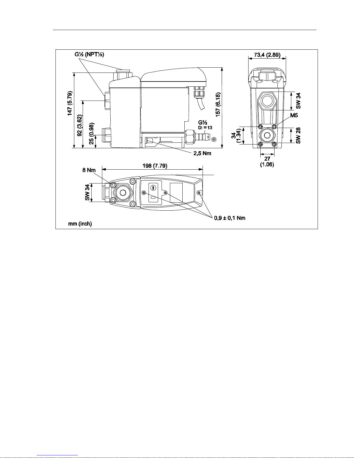
7 Dimension drawing
Pos:33 / Beko TechnischeDokument ation/Techn ischeDaten/ Masszeic hnung@ 0\m od_1184569815280_2901.docx @ 6140@ @1
Pos:34 / Beko TechnischeDokument ation/Techn ischeDaten/ Masszeic hnungErgänz ungSW @ 1\m od_1250153244115_2901.docx @ 15481@ @1
SW = wrench size
Pos:35 / ---- Seitenumbruch ---- @0\mod_1157028099015_0.docx @ 2903 @ @1
Climate zones and performance data
10 BEKOMAT® 33U / 33U CO
Pos:36 / Beko TechnischeDokument ation/Überschrift en/1/ Klimazonenund Leistungsdaten @ 0\m od_1183638385480_2901.docx @ 5583@ 1 @ 1
8 Climate zones and performance data
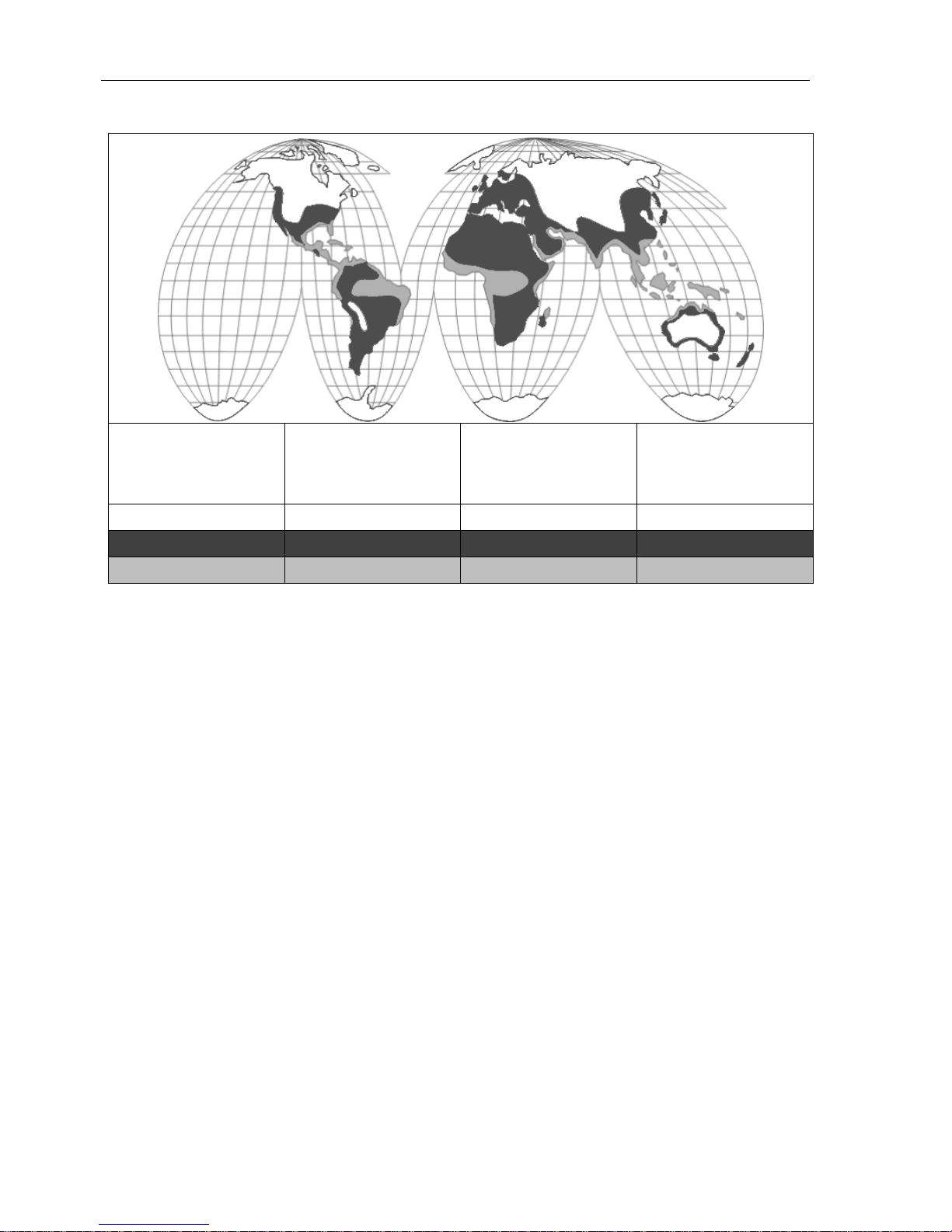
Pos:37 / Beko TechnischeDokument ation/Klimazonen/K limazonen BM @ 0\mod_1184573462796_2901.docx @ 6180 @ @1
Climate zone
Max.
compressor perfor-
mance
m³/min.
Max.
dryer performance
m³/min.
Max. filter performance
m³/min.
green 12 24 120
blue 10 20 100
red 7 14 70
The indicated performance data are based on a moderate climate and apply to Europe, large parts of Southeast Asia, North and South Africa, parts of North and South America (climate zone: blue).
For dry and / or cool climate (climate zone: green) , the following factor applies: performance in the "blue"
climate zone approx. x 1.2
For warm and / or humid climate (tropics; climate zone: red), the following factor applies: performance in the
"blue" climate zone approx. x 0.7
Pos:38 / ---- Seitenumbruch ---- @0\mod_1157028099015_0.docx @ 2903 @ @1
Function
BEKOMAT® 33U / 33U CO 11
Pos:39 / Beko TechnischeDokument ation/Überschrift en/1/ Funktion@ 0\mod_1183637775808 _2901.docx @ 5403@ 1 @ 1
9 Function
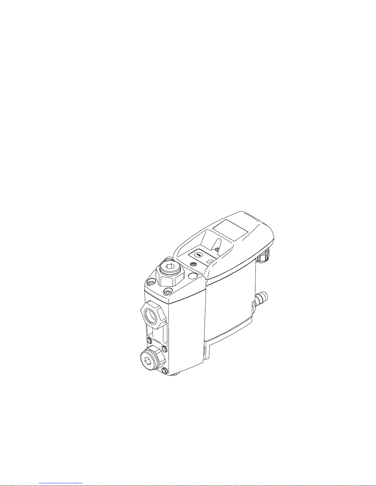
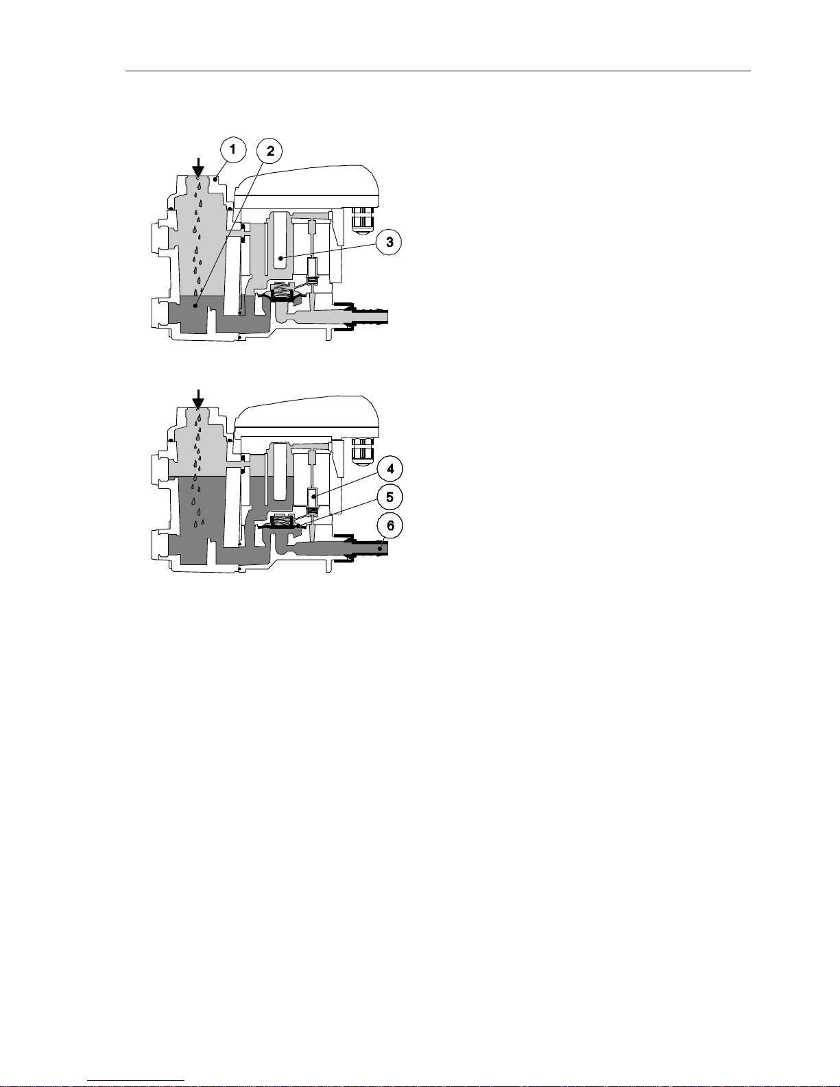
Pos:40 / Beko TechnischeDokument ation/Funktion/B EKOMAT/BM Ableitfunktion @ 0\ m od_1183618031702_2901.docx @ 4032@ @1
Via the inlet line (1) the condensate flows into the
BEKOMAT®33U / 33U CO and accumulates in the
housing (2).
A capacitively functioning sensor (3) continuously registers the filling level and relays a signal to the electronic control as soon as the container is filled.
The pilot valve (4) is activated and the membrane (5)
opens the outlet line to discharge the condensate (6).
When the BEKOMAT®33U / 33U CO is empty, the
outlet line is reclosed tightly in time before unnecessary compressed-air losses occur.
Pos:41 / Beko TechnischeDokument ation/Funktion/B EKOMAT/BM 32U/33 U LED-Taster- Funktio n @ 4\mod_1354691493582_2901. docx @ 29040@ @1
 Loading...