

Page 1
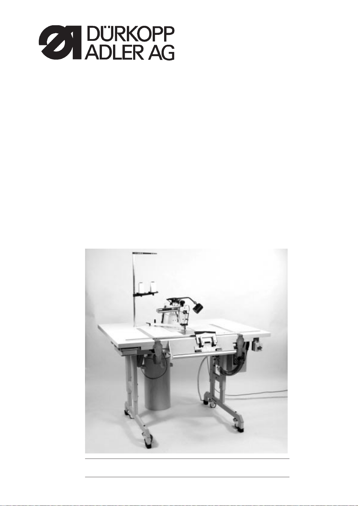
739-23
Sewing Machine for Small Parts
Operating Instructions
Installation Instructions
Maintenance instructions
Programming Instructions
P.O. Box 17 03 51, D-33703 Bielefeld • Potsdamer Strasse 190, D-33719 Bielefeld
Telephone +49 (0)521 925 01 • Fax +49 (0)521 925 13 15
Page 2

Page 3

Contents Page:
Introduction and general safety instructions
Part 1: Operating Instructions Class 739-23
1. Product description ............................................ 5
1.1 Proper use .................................................. 5
1.2 Summary description ............................................ 5
1.2.1 Introduction .................................................. 5
1.2.2 Sewing machine head ........................................... 6
1.2.3 Material transport .............................................. 6
1.2.4 Dürkopp-Adler Control (DAC) ....................................... 6
1.3 Technical data ................................................ 6
1.4 Auxiliary equipment ............................................. 7
2. Operation of the sewing machine head ................................ 8
2.1 Recommended threads ........................................... 8
2.2 Replacement of needle ........................................... 9
2.3 Inserting of needle thread ......................................... 11
2.4 Needle thread monitor ........................................... 11
2.5 Adjustment of needle thread tension ................................... 13
2.6 Opening of needle thread tensioner ................................... 13
2.7 Adjustiment of thread regulator ...................................... 14
2.8 Winding of bobbin thread .......................................... 15
2.9 Replacement of bobbin ........................................... 16
2.10 Adjustment of bobbin thread tension ................................... 17
2.11 Inserting of needle and bobbin thread in thread scissors ....................... 18
3. Inserting of material in material clamps ............................... 19
4. Switching on of sewing machine and infeed of material clamps ................ 20
4.1 Switching on of sewing machine ..................................... 20
4.2 Infeed of material clamps.......................................... 21
4.3 Starting of sewing operation ........................................ 21
4.4 Termination of sewing operation ..................................... 21
5. Maintenance ................................................. 22
5.1 Tilting of machine head ........................................... 22
5.2 Cleaning and inspection .......................................... 22
5.3 Lubrication .................................................. 25
Page 4

Page 5

1. Product description
1.1 Proper use
The Dürkopp-Adler 739-23 sewing machine has been specifically
designed for the processing of lightweight and medium weight
materials. Such materials generally consist of textile fibres and is used
in the clothing industry. The sewing machine can within certain
limitations also be used for technical seams. In this case, the operator
must ensure, that such applications are not carried out on a regular
basis and with a limited number of patterns and materials (please also
contact the Dürkopp Adler AG service department, who will be
delighted to assist you). Depending on the result, it might be necessary
to take suitable safety measures.
Generally, only dry material should be processed with this machine.
The thickness of the material may not exceed 3 mm when compressed
by the lowered sewing foot. The material may not contain any hard
objects. Otherwise, the operator must wear goggles. Suitable eye
protection is currently not available.
The seam is generally produced by textile threads (65/2 Nm for
synthetic fibres and 50/2 Nm for core spun. For other threads, the
operator must previously assess the risk involved and take suitable
precautionary measures.
The sewing machines may only be installed and operated in dry and
well-maintained rooms. If the sewing machine must be used in other
rooms,
additional measures might be necessary, that have to be agreed upon
by the manufacturer (see EN 60204-31: 1999).
As a manufacturer of industrial sewing machines, we assume that our
products are operated by personnel who are suitably trained, and we
thus assume that the general operation of machines and the potential
risks are known to the operating staff.
1.2 Summary description
1.2.1 Introduction
The 739-23 is a sewing machine specifically designed for the
production of predefined seams, as found for example in flaps, cuffs,
waistband extensions, etc.
The cut material is manually inserted into the material clamp, which is
then placed in the guide of the sewing machine. Press the start key “S”
at the key bar to start the sewing process.
The seam beginning and the seam end can be locked, and the threads
are automatically cut off.
The data regarding the course of the seam and the contour are saved
in a transponder located on the material clamp.
1-5
Page 6

1.2.2 Sewing machine head
1.2.3 Material transport
1.2.4 Dürkopp-Adler Control (DAC)
–
Single-needle double lockstitch machine
–
The seam beginning and end are locked by means of tacks (single
tacks, double tacks) or stitch condensation.
–
Thread cutter
–
An electronic thread monitor ensures that the machine is not
restarted in the event of a thread break or if the bobbin is empty.
–
Edge cutter
The material transport is driven by step motors. This drive system
allows for short running times and ensures the exact positioning of the
sewing and transport tracks, due to its high repeat accuracy.
contributing thus to a high standard quality at high productivity.
The machine head is driven by D/C motor.
The DAC includes the extensive MULTITEST testing and monitoring
system.
A microcomputer controls and monitors the entire sewing process and
informs the operator on errors and disruptions by means of messages
on the display of the operating panel.
1.3. Technical data
Machine head: class 271
Needle system: 2134-85
Needle strength: Nm 100
Stitch type: single-needle double lockstitch
Number of stitches: 200 - 4000 r.p.m.
Stitch length: 2.0 to 4.0 mm
Stitch condensation: 0.5 to 2.25 mm
Edge cutter: rotating, positioned around the needle centre
Cutting distance: Depending on sewing system
E1/4 for 4 mm
E1/5 for 5 mm
Blade lift: 5.5 mm
1-6
Page 7

1.4 Auxiliary equipment
Operating pressure: 6 bar
Air consumption: 0.05 NL per cycle
Nominal voltage: 190 - 240 V, 50/60 Hz
Dimensions:
Table height: 820 - 1080 mm
Weight: 230 kg
Noise level : Lc = 80 dB (A)
Emissions per workplace
according to DIN 45635-48-B-1
Stitch length: 2 [mm]
Number of stitches: 2000[min-1]
Sewing material: G1 DIN23328 2 -play
0739 597514 Sewing lamp
0797 003031 Pneumatic connection set
9859 073901 Programming software CD 739
9850 739007 Transponder loader
9800 810001 1 Centrifugal blower (3x 380 - 415V/ 50Hz)
9800 810001 2 Centrifugal blower (3x 220 -240V/ 50Hz)
9800 810001 2 Centrifugal blower (3x 220 -240V/ 60Hz)
1-7
Page 8

2. Operation of the sewing machine head
2.1 Recommended threads
The following core spun threads cater for high quality seams and
interruption-free processing:
Double polyester endless polyester spun (e.g. Epic Poly-Poly, Rasant
x, Saba C, etc. )
double polyester endless cotton spun (e.g. Frikka, Koban, Rasant,
etc.)
If these products are not available, use the cotton and polyester
threads listed in the table.
Double core spun threads are in many cases offered by yarn
manufacturers under the same trade name as triple polyester fibre
threads (3-cylinder spun). This may lead to a certain confusion
regarding twisting and thread thickness.
If in doubt, open the thread and check whether it is double or triple
spun.
Number 120 on the label of a yarn reel of a core spun thread
corresponds for example to thickness Nm 80/2 (see values shown in
brackets in the table).
For monofile threads, needle thread and bobbin thread may be of the
same thickness. The best results are achieved, if the threads are soft
and elastic (software) and with a thickness of 139 Denier.
Recommended thread thickness
Needle strength Needle threadNeedle thread Position of Bobbin thread Bobbin thread
Nm tension thread regulator tensions
[g] [g]
100 cotton 60 - 100 3,5 cotton 30 - 40
NeB 50/2 70 - 100 NeB 50/2
Poly-Poly Poly-Poly
Nm 65/2 Nm 65/2
(Prod. 100) (Prod. 100)
1-8
Page 9

2.2 Replacement of needle
21
Caution: risk of injury!
Switch off main switch.
Never replace needle while the main switch is on.
–
Loosen screw 1 and remove needle from the needle bar 2.
–
Insert new needle to the stop in the hole in the needle bar 2.
Caution!
The needle scarf must face away from the operator and towards the
hook.
–
Tighten screw 1.
1-9
Page 10

1
12
2
1-10
8
7
9
10
11
3
4
5
6
Page 11

2.3 Inserting of needle thread
Caution: risk of injury!
Switch off main switch.
Never insert the needle thread while the main switch is on.
To insert the needle thread, please proceed as shown in the above
figures and in sequence of the numbers.
–
Place yarn reel onto the yarn stand.
–
Insert thread from the reel through hole 1 of the reeling bracket.
–
Insert thread through guide 2.
–
Insert thread through thread regulator 3.
–
Insert thread in clockwise direction into the thread tensioner 4, over
the thread tensining spring 5 and below guide 6.
–
Pull thread through guide 7 and thread regulator 3 upwards to the
thread lever.
–
Insert thread trough the hole in thread lever 8 and again through
guide 7.
–
Insert thread through the thread monitor 9 and guide 10.
–
Insert thread through the belt wheel 11 to the needle.
–
Insert thread in needle 12.
2.4 Needle thread monitor
The needle thread is monitored by means of switch 9.
If the thread is broken or the end of the thread is reached, the switch is
not activated.
Caution: risk of injury!
Switch off main switch.
Do never insert the needle thread while the main switch is on.
–
Insert needle thread.
–
Switch on main switch.
–
Start new sewing process
1-11
Page 12

1
Fig. A: Correct thread run at the centre of the
sewing material
Fig. B: Insufficient needle thread tension
or
excessive bobbin thread tension
Fig. C: Excessive needle thread tension
or
insufficient bobbin thread tension
1-12
Page 13

2.5 Adjustment of needle thread tension
Main tension
The main tension 1 must be set to the lowest possible value.
The looping of the threads must be positioned at the centre of the
sewing material.
In thin materials, excessive thread tensions can result in gathering or
breaking threads.
The main tension 1 must be adjusted in such a way that a regular stitch
pattern is achieved.
–
To increase tension
Turn knurled nut clockwise
–
To reduce tension
Turn knurled nut anticlockwise
2.6 Opening of needle thread tensioner
Automatic
Upon cutting of the thread, the needle thread is automatically lifted.
1-13
Page 14

2.7 Adjustment of needle thread regulator
32 1
Caution: risk of injury!
Switch off main switch.
Never adjust thread regulator while the main switch is on.
The thread regulator 2 controls the length of thread that is necessary
for a stitch.
Good seams can only be achieved, if the thread regulator is adjusted
to the correct value.
The adjustment of the thread regulator is affected by the following
factors:
–
Stitch length
–
Thickness of sewing material
–
Properties of thread
If adjusted correctly, the needle thread loops easily across the thickest
section of the hook at minimum tension.
–
Loosen screw 1.
–
Adjust position of thread regulator 2.
–
Tighten screw 1.
Hint:
If the regulator is correctly set, the thread tensionging spring 3 is
moved by approx. 1 mm from its top end position. This is the case, if
the needle thread loop passes the section of the hook with the largest
diameter.
1-14
Page 15

2.8 Winding of bobbin thread
1
The bobbin thread is automatically wound up during the sewing
operation, provided that winder flap 2 is closed.
–
Remove all threads from the bobbin hub.
–
Place yarn reel onto the yarn stand.
–
Insert thread through hole 1.
–
Insert thread through guide 4 and the bobbin thread tensioner 5.
–
Wind thread in clockwise direction around the bobbin hub and cut
off at hook 3.
–
Close bobbin flap 2.
The winder is automatically switched on and ready for operation.
–
Start sewing operation.
As soon as the bobbin is full, the winder is automatically switched off.
To adjust the number of windings on the bobbin, please refer to the
service instructions.
54 3 2
1-15
Page 16

2.9 Replacement of bobbin
321
Caution: risk of injury!
Switch off main switch.
Always switch off main switch before you replace the bobbin.
Removing bobbin
–
Switch off main switch
–
Press down cover plate 1.
–
Lift bobbin case flap 2.
–
Remove bobbin housing 3 together with bobbin.
–
Take bobbin 7 from the bobbin housing body 3.
Inserting new bobbin
–
Place new bobbin in the bobbin case body.
Observe direction of rotation of the bobbin.
–
Insert bobbin thread through slot 5 below the tension spring 4 to
hole 6.
–
Pull approx. 5 cm of bobbin thread from the bobbin housing 3.
When pulling the thread, the bobbin must rotate in the direction of
the arrow.
–
Insert bobbin housing 3.
–
Close bobbin case flap 2.
76 54 3
1-16
Caution: risk of breakage!
Insert bobbin housing by firmly pressing it into the recess and ensure
that it is properly locked in.
Page 17

2.10 Adjustment of bobbin thread tension
1
2
5
Caution: risk of injury!
Switch off main switch.
Never adjust bobbin thread tension while the main switch is on.
The required bobbin thread tension must be generated by means of
tension spring 5.
The brake spring 1 must be fully reset.
Adjustment of tension spring
–
With full bobbin, the bobbin case body 2 should slowly fall down
due to its own weight (see figure to the right).
–
Adjust tension spring 5 with regulating screw 4, until the required
tension is established.
4
3
1-17
Page 18

2.11 Inserting of needle and bobbin thread in thread scissors
2 1
To ensure that the sewing machine is able to continue sewing after the
replacement of a reel or bobbin, the needle and bobbin thread must be
inserted into thread scissors 2.
–
Pull needle and bobbin threads to the left.
–
Press key “1" at the operating panel.
The thread scissors 2 are lifted for a short moment.
–
Pull needle and bobbin threads beneath the thread scissors.
Both threads are cut and held by the blades.
1-18
Page 19

3. Inserting of material in material clamps
21
Example: Inserting of a pocket flap
–
Place material clamp 1 onto holder 2.
–
Open material clamp
–
Place lining material 5 with the right side upwards into the material
clamp.
–
Place outside fabric 4 with the right side downwards into the
material clamp.
Both pieces of material must touch the stop. At the edges, they must
be aligned in such a manner that there is the same amount of excess
material to the right as to the left.
–
Press down lever 3.
The material clamp is closed.
Clamping force of material clamps
Depending on the thickness of the material, it might occur that the
material clamps cannot or can only barely be closed.
In this case, the clamping force must be adjusted (see maintenance
instructions).
543
1-19
Page 20

4. Switching on of sewing machine and infeed of material clamps
4.1 Switching on of sewing machine
1
–
Switch on main switch 1.
The control system is initialised.
The start message is displayed.
Prior to working with the sewing machine, the sewing axes must be
positined in the reference position.
CAUTION!
The reference run must be carried out by the operating staff.
CAUTION! Risk of breakage!
The material clamp may not be inserted during the reference run.
The following message indicates that a reference run is required.
To remove a material clamp that is still inserted in the machine use the
arrow keys “ “ and ” “ to manually move and remove it.
–
Press “OK” key.
The reference run is carried out.
After the reference run has been completed successfully, the display
changes to:
1-20
After 0.5 seconds, the machine program changes to operating mode.
Page 21

4.2 Infeed of material clamps
21
Caution: risk of breakage!
Do not insert material clamps that are not properly closed.
–
Place mateial clamp on guide rod 1 and press until it is engaged in
the toothed profile 2.
4.3 Starting of sewing operation
–
Press key “S”.
The sewing operation is started. The material clamp is pulled in.
Insert additional material clamps for continuous processing.
4.4 Termination of sewing operation
“ESC” “OK”
–
Press key “ESC”.
The sewing operation is terminated.
–
Press “OK”.
The display reads as follows, indicating that a reference run is
required:
To remove material clamp that is still inserted in the machine use the
arrow keys “ “ and ” “ to manually move and remove it.
1-21
Page 22

5. Maintenance
5.1 Tilting of machine head
321
5.2 Cleaning and inspection
4
For maintenance work to be carried out below the base plate, the
sewing machine head can be swiveled backwards and placed on the
machine support.
Caution! Risk of injury!
Switch off main switch.
–
Loosen clamping lever 3.
–
Remove suction pipe 2.
–
Swivel operating panel 1 forward.
–
Tilt machine head 4 backwards.
1-22
Caution! Risk of injury!
Switch off main switch. Never carry out maintenance work while the
main switch is on.
The maintenance tasks must be carried out on a regular basis and at
the intervals given in the schedules (see column “Operating hours”). If
fluffy material is processed, it might be necessary to service the unit at
shorter intervals.
Clean machines are less prone to disruptions!
Page 23

1
2
3
Maintenance tasks Description Operating
to be carried out hours
Sewing machine head
- Remove dust, pieces of thread
and
cut-offs
(e.g. with pressure air gun)
Control cabinet
- Remove sewing dust
(e.g. with pressure air gun)
Areas requiring special attention:
- Area around the bobbin 1
- around the thread lever 2
- around the edge cutter 3
Two blower filters 4 of the control cabinet
4
8
8
1-23
Page 24

4
2
6
8
10
54
87 6
aintenance tasks Description Operating
to be carried out hours
Waste container
Extractor system
Empty waste container 5.
Empty dust bag 4.
8
Pneumatic system
- Inspect water level at pressure
regulator.
The water level may not reach the filter cartridge 6.
- Drain water (under pressure) from water separator 8
40
by turning the drain screw 7.
The filter cartridge 6 ensures that dirt and condensation
500
- Clean filter cartridge 6.
water are removed.
- Disconnect sewing machine from air pressure supply.
- Secure drain screw 7.
The pneumatic system of the sewing machine must be
relieved from pressure.
- Inspect system for leakage
1-24
- Remove water separator 8.
- Remove filter cartridge 6.
Clean filter shell and cartridge with
cleaning spirit (do not use solvents!) and blow
dry.
- Assemble water separator 6 and connect
maintenance unit.
500
Page 25

5.3 Lubrication
1
Caution! risk of injury!
Lubricants may cause irritation to skin.Therefore avoid all contact with
skin. If skin is contaminated, clean thoroughly with plenty of water.
CAUTION!
The handling and disposal of mineral oils is regulated by law. Oil must
be disposed of through authorised dealers. Protect the environment
and never spill any oil .
To refill the oil tank, use only ESSO SP-NK 10 lubricant or a similar
product of the following specification:
Viscosity at 40° C: 10 mm2/s
Ignition point 150° C
ESSO SP-NK 10 is available from all DÜRKOPP-ADLER AG agencies
and has the following parts numbers:
2 litre container: 9047 000013
5 litre container: 9047 000014
2
Maintenance tasks Description Operatingto be carried out hours
Sewing machine head The sewing machine head is equipped with a central oil
wick. All bearings are lubricated from oil tank 1.
- The oil level in the oil tank 1 may never fall below the
“MIN” mark.
- Refill tank through the opening in the window until the
oil level reaches the “MAX” mark.
Edge cutter Lubricate the bearings of the edge cutter 2 with one
drope of il
8
8
1-25
Page 26

 Loading...