

Page 1

Closing Seam Machine 1282-4 Working Instructions
V
Beisler Automated Sewing Equipment
Working Instructions
Closing Seam Machine 1282-4
ersion 1.1, 14.05.03
- 1 -
Page 2

Beisler Automated Sewing Equipment
Contents of the working instructions
The working instructions are divided into four sections:
A General notes
Safety instructions for the operating and service personnel and for the operator of the machine.
B Operating instructions
Instructions for the personnel operating and handling the machine.
C Service instructions
Instructions for the personnel in charge of the initial start-up, setting up and
service of the machine.
Closing Seam Machine 1282-4 Working Instructions
D Programming instructions
Instructions for the service personnel in charge of preparing and setting up the
machine.
Scope of the working instructions
These working instructions describe the CLOSING SEAM MACHINE 1282-4 of Beisler
GmbH and apply only to those machine parts and components that are contained in
the scope of delivery of the CLOSING SEAM MACHINE 1282-4 .
They do not apply to accessories or machine parts (e.g. sewing head) from third parties
that the machine is equipped or retrofitted with. For those components, the working
instructions of the respective manufacturer or supplier apply.
- 2 -
Page 3

Closing Seam Machine 1282-4 Working Instructions
Beisler Automated Sewing Equipment
Section A
General notes
- 3 -
Page 4

Beisler Automated Sewing Equipment
Closing Seam Machine 1282-4 Working Instructions
General notes
Section A
Contents Page
A.1 Safety instructions ......................................................................................................................................5
Important information for the operator......................................................................................................5
Warranty...................................................................................................................................................5
Exclusion of liability ..................................................................................................................................6
Copyright ..................................................................................................................................................6
Important information for the operating personnel ...................................................................................7
Important information for the service personnel.......................................................................................7
A.1.1 Symbols used in the working instructions ....................................................................................................8
A.1.2 Symbols used on the machine......................................................................................................................8
A.1.3 General safety instructions ...........................................................................................................................9
- 4 -
Page 5

Closing Seam Machine 1282-4 Working Instructions
Safety instructions
A.1
Important information for the operator!
This machine has been manufactured in keeping with the latest technological developments and is operationally safe. However, it may present potential hazards, p articularly if it is operated by inadequately trained personnel or if it is not used correctly:
• For personnel operating and handling the machine, the operator must prepare written
instructions in a reasonable form and in the language of the operating personnel
based on these working instructions (Germany: Accident Prevention Regulations UVV
VGB 1 § 7.2).
• Use the operating instructions to familiarize the operating personnel with the functions, operation, and care of the machine and check to see if the operating personnel fully understands these instructions.
• Use the service instructions to familiarize the service personnel with the setting
up and maintenance of the machine.
• For any modifications of the machine that have not been approved by Beisler GmbH
in writing, the operator is fully responsible.
• The contents of the working instructions are subject to change without further notice.
• Concerning translations into foreign languages, the German version of these working
instructions is binding.
• Should you encounter problems that are not mentioned in these working instructions, please contact your supplier immediately for your own safety . Please do not
hesitate to contact Beisler if you have any suggestions that help to improve this
product.
• Keep these working instructions close to the machine so that safety instructions and information on operation, setting-up, and maintenance are always
accessible.
Beisler Automated Sewing Equipment
Warranty
Beisler GmbH warrants the safety , operatability, and rep air without charge of the CLOSING SEAM MACHINE 1282-4 for a period of 6 months under the condition that:
• the machine is used exclusively for the intended purpose and serviced in accordance with the information in these working instructions,
• modifications of the machine are carried out only with prior written approval of Beisler
GmbH,
• only original spare parts or accessories approved by Beisler GmbH are used. For
a complete list of all approved spare parts, please contact Beisler GmbH.
If the machine is used for more than 10 hours per day (shift operation), the warranty
period is reduced to 3 months.
The warranty period starts with the delivery of the machine to the operator.
- 5 -
Page 6

Beisler Automated Sewing Equipment
Safety instructions
A.1
Exclusion of liability
Beisler GmbH warrants the faultlessness of the product as set forth by their
advertisements, product information and these working instructions. Other product characteristics are not warranted.
Beisler GmbH is not responsible for the profitability or for the correct function
of the CLOSING SEAM MACHINE 1282-4 if it is used for other purposes than
those defined in section „Correct use“.
Beisler GmbH is not responsible for damage that arises from the use of nondefined and non-approved spare parts or accessories.
Copyright
© 2000 Beisler GmbH, Hösbach; 06/2001
Closing seam machine
The CLOSING SEAM MACHINE 1282-4 and all related parts are protected by
copyright. Any reproduction of the machine will be prosecuted.
Closing Seam Machine 1282-4 Working Instructions
Working instructions
These working instructions are protected by copyright. No part of the working
instructions, including figures and tables, may be reproduced or translated in
any form or by any means, electronic or mechanical, without the express written
permisson of Beisler GmbH.
Beisler GmbH
Fohnradstr. 10
63768 Hösbach
Germany
Phone: ++ 49 / 6021 / 50 19 0
Fax: ++ 49 / 6021 / 50 19 10
eMail: vertrieb@beisler-gmbh.de
- 6 -
Page 7

Closing Seam Machine 1282-4 Working Instructions
Safety instructions
A.1
Important information for the operating personnel!
Please note that any work to the CLOSING SEAM MACHINE 1282-4 must be carried out only by trained operating personnel:
• Operating personnel means persons:
that have been given initial instructions for sewing automats and that
have been trained for the operation and handling of the CLOSING SEAM
MACHINE 1282-4 on the basis of these operating instructions,
that have been informed about potential risks arising from their work
with the machine,
that are capable of assessing their work with the machine due to occupational experience and instruction of the safety regulations and of
recognizing potential hazards during work.
• Cleaning of the machine or of machine parts must be performed only by personnel that has been informed about potential hazards arising during the cleaning work.
• Prior to the initial operation of the CLOSING SEAM MACHINE 1282-4, read the
operating instructions carefully so that you can make full use of the advantages
of the machine and to prevent damage.
Beisler Automated Sewing Equipment
Important information for the service personnel!
Please note that service work to the CLOSING SEAM MACHINE 1282-4 must be carried out only by authorized and adequately trained expert personnel:
• Expert personnel means persons:
that have aquired their expertise by a special training in machine technology or electrical engineering or by a special advanced training or a
comparable qualification,
that have acquired the knowledge required to perform all works for setting up and servicing the CLOSING SEAM MACHINE 1282-4 from a training by Beisler GmbH,
that are capable of assessing their work with the machine due to occupational experience and instruction of the safety regulations and of
recognizing potential hazards during work.
• Prior to carrying out any service work to the CLOSING SEAM MACHINE 12824, read the entire working instructions carefully so that you can make full use
of the advantages of the machine and to prevent damage.
- 7 -
Page 8

Beisler Automated Sewing Equipment
Safety instructions
A.1
Closing Seam Machine 1282-4 Working Instructions
A.1.1 Symbols used in the working instructions
WARNING!
is used if non-observance may cause serious or even lethal
injuries.
CAUTION!
is used if non-observance may cause medium to minor
injuries or damage.
NOTE!
is used for hints and useful information.
A.1.2 Symbols used on the machine
WARNING: DANGER!
Caution! Observe working instructions.
WARNING: HIGH VOLTAGE!
Caution! Prior to opening, pull out power plug.
- 8 -
Page 9

Closing Seam Machine 1282-4 Working Instructions
Safety instructions
A.1
A.1.3 General safety instructions
Beisler Automated Sewing Equipment
Correct use
• The CLOSING SEAM MACHINE 1282-4 is a sewing
machine for the contour-identical sewing of side components, particularly for closing front and rear trouser
components with or without lining.
The side seam can be sewn with a braid pocket, a wing
pocket or a pocket integrated in the side seam.
• The machine can be used for all materials commonly used for outerwear.
• The machine has been designed for permanent operation in industry.
• The CLOSING SEAM MACHINE 1282-4 has been tested for electromagnetic compatibility and is suited for
installation in industrial operating rooms.
Incorrect use
• The CLOSING SEAM MACHINE 1282-4 must not be
operated in rooms that do not comply with the location requirements.
• The CLOSING SEAM MACHINE 1282-4 must not be
operated in the vicinity of devices or systems that produce strong magnetic fields as otherwise the correct
function of the program control may be impaired.
Safety requirements
• DIN EN, Part 1:1991-11, Part 2:1995-06
Safety of machines.
• DIN EN 60601, Part 1:1994-05
Safety regulations for electrically operated measuring
and control installations, general requirements.
• DIN EN 50178 (VDE 0160): 1998-04
Equipment of power systems with electronic devices.
• DIN EN 50082 (VDE 0839) Part 2:1997-11
Electromagnetic compatibility, basic specification,
immunity to interference.
Part 1: Domestic, business and commerce, small
enterprises.
Part 2: Industry.
• DIN EN 60204 (DIN VDE 0113): 1993-06
Electrical equipment of industrial machines
Safety devices
The CLOSING SEAM MACHINE 1282-4 is equipped with
a circuit-breaker (program stop switch) that stops all
machine movements and the sewing process when actuated manually.
Power supply connection
The power supply of the machine is established with a
properly grounded power supply connection with:
• 230 V ± 10 %, 50/60 Hz, grounding plug.
• Fusing: 16 A
• Power consumption: 1.3 kW
Compressed air supply
The machine must be supplied by an on-site compressed
air source.
• Operating pressure: 6 bar.
• Compressed air quality: oil-free
• Compressed air consumption: 12 NL
Location and storage requirements
Installation in sheltered, closed rooms.
• Room temperature: 10 °C to 45 °C
• Relative humidity: 80 % max.
Disposal
• Please discard the packaging material in accordance
with existing disposal directives. Section C1, Delivery of the machine, contains a list of the packaging
materials used.
• The machine contains reusable materials. Therefore,
when discarding the machine, ask your local magistrate or community office about the possibilities of
recycling.
- 9 -
Page 10

Closing Seam Machine 1282-4 Working Instructions Beisler Automated Sewing Equipment
Section B
Operating Instructions
- 1 -
Page 11

Beisler Automated Sewing Equipment
Closing Seam Machine 1282-4 Working Instructions
Operating Instructions
Section B
Contents Page
B.1.1 Functional units ...................................................................................................................................................3
B.2.1 Functional sequence...........................................................................................................................................4
B.2.2 Lining up/aligning trousers components.............................................................................................................4
B.2.3 Transport and sewing..........................................................................................................................................7
B.2.4 Switches..............................................................................................................................................................9
B.2.5 Operating panel.................................................................................................................................................10
B.3.1 Safety instructions for operation .......................................................................................................................11
B.3.2 Preparing the machine......................................................................................................................................12
B.3.3 Selecting the sewing program ..........................................................................................................................13
B.3.4 Manual sewing ..................................................................................................................................................14
B.3.5 Operating the stacker........................................................................................................................................14
B.3.6 Threading ..........................................................................................................................................................14
B.3.7 Line-up and alignment of sewing pieces ..........................................................................................................15
B.3.8 Starting machine cycle......................................................................................................................................16
B.3.9 Resetting insertion process .............................................................................................................................18
B.3.10 Moving machine to zero position ....................................................................................................................19
B.3.11 Stopping a sewing program ............................................................................................................................19
B.3.12 Turning the machine off ..................................................................................................................................19
B.3.13 Periodic cleaning of the machine....................................................................................................................20
- 2 -
Page 12

Closing Seam Machine 1282-4 Working Instructions Beisler Automated Sewing Equipment
Description of the machine
B.1
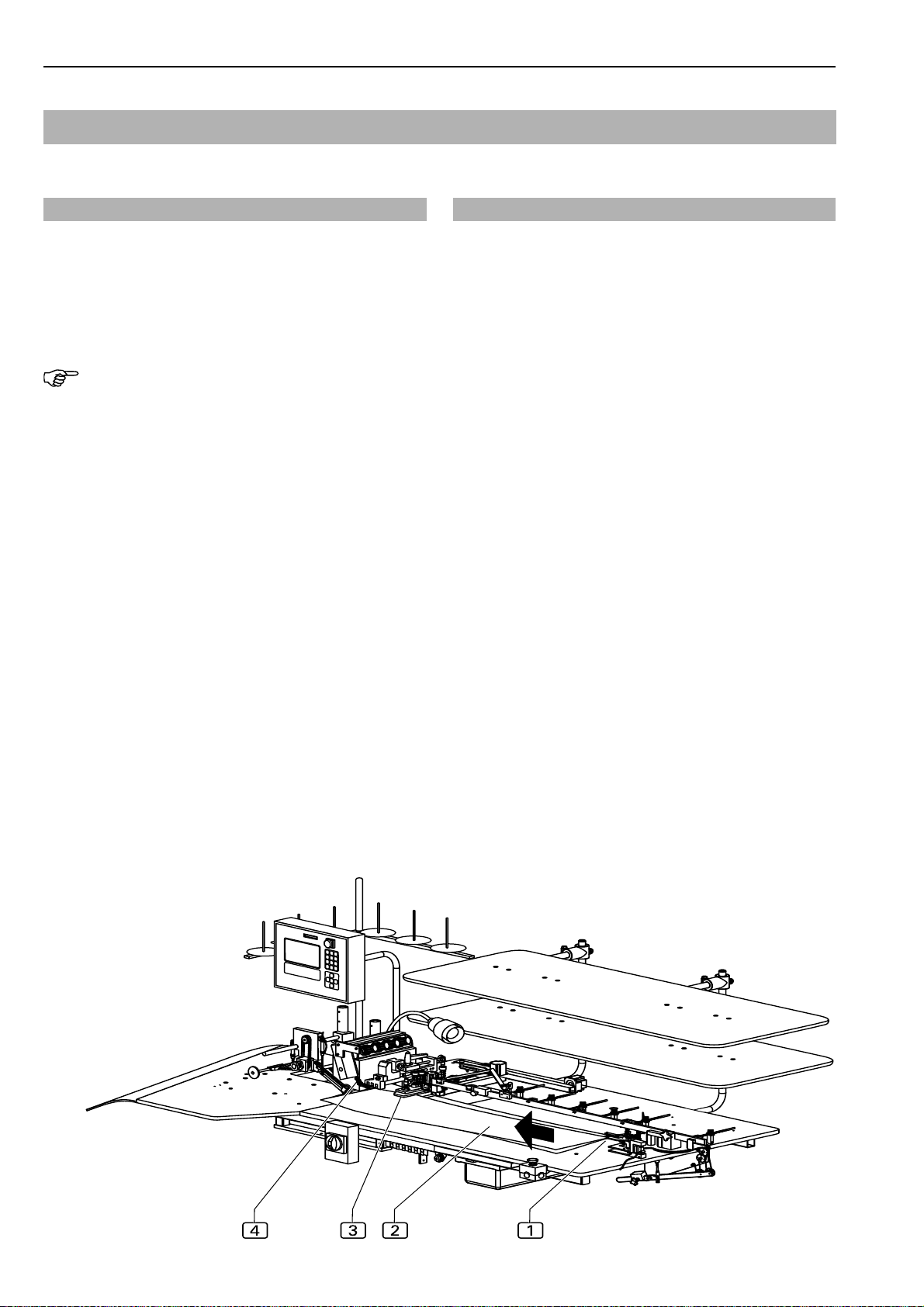
B.1.1 Functional units
All functional units of the closing seam machine 1282-4
are mounted to the height-adjustable table frame and freely
accessible.
1
Height-adjustable table leg
2
Main switch, emergency off switch
3
Stacker
4
Sewing head with sewing unit
5
Transport unit
6
Operating panel with memory card
7
Thread holder
Fig. 1
8
Contour guide
9
Storage plate
a
Guide rail with guide clamp
b
Counterweight and return lever
c
Reset button
d
Kneeswitch for machine operation
e
Footswitch for machine operation
f
Waste container
g
Sewing head drive
h
Footswitch for stacker
Fig. 1
- 3 -
Page 13
Beisler Automated Sewing Equipment
Functions of the machine
B.2
Closing Seam Machine 1282-4 Working Instructions
B.2.1 Functional
The CLOSING SEAM MACHINE 1282-4 allows the contour-identical sewing of front and rear trousers components in side and crotch seams. The side seam can be sewn
with a braid pocket, a wing pocket or a pocket that is integrated to the side seam.
NOTE - Possible applications!
The CLOSING SEAM MACHINE 1282-4 has been designed predominantly for the sewing of trousers components. Therefore, the operation of the machine is described in these instructions using trousers components as
examples.
However, the machine can also be used for processing
other sewing pieces, e.g. sleeves, rear seams of jackets
etc. The prerequisite for the correct function is always that
the length of the sewing pieces does not exceed the clear
distance between the sewing head and the start position
of the guide clamp and that the width of the sewing pieces does not exceed the distance between guide rail and
worktable front edge.
of the machine
Fig.2
B.2.2 Lining up/aligning trousers components Fig. 2
The front and rear trousers components are placed onto
one another with flush seams. The sequence for lining up
the trousers components depends on the seam to be
effected:
• For sewing the crotch seam, the rear component is
below, the front component is up. For sewing the side
seams of these trousers components, the rear component is up, the front component is below.
• For sewing the right trousers components, the sequence is inversed.
The two trousers components 2 are inserted, with the
hip side oriented toward the sewing unit 4, into the
guide clamp 1where they are secured with the needle.
If equipped with the optional cloth transfer machine component, the trousers components ends are inserted at the
cloth transfer station where they are transferred to the guide clamp and secured.
Then, the two trousers components are aligned with the
contour guide 3 and lined up at the stop of the sewing
unit4.
Machine cycle:
Insertion process and machine cycle are effected from left
to right:
• The trousers components are lined up to guide clamp
1
, contour guide 2 and sewing unit 3.
• Top and bottom transport element of the sewing unit
and the puller transport the sewing pieces to the sewing unit to be tucked and from there to the stacker.
• During the sewing process, the automatic contour guide
controls the routing of the seam.
Fig. 2
- 4 -
Page 14
Closing Seam Machine 1282-4 Working Instructions Beisler Automated Sewing Equipment
Functions of the machine
B.2
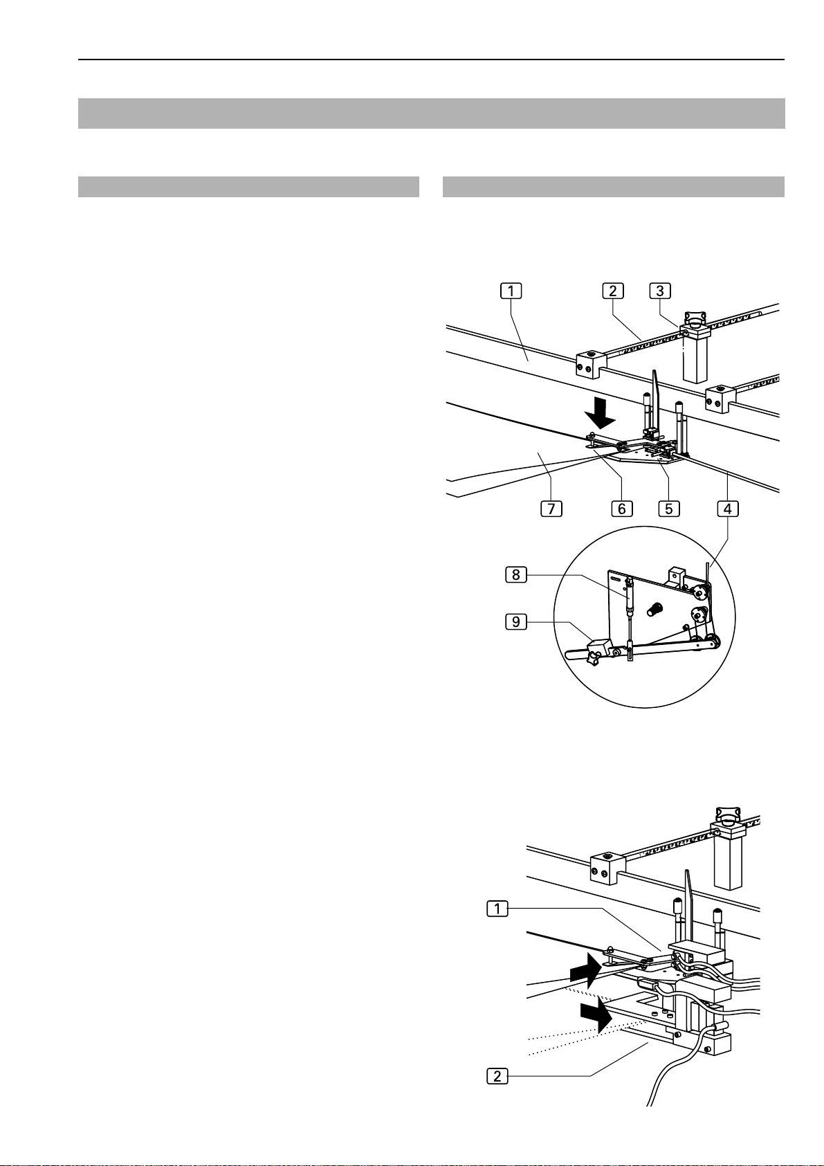
Fig. 3/4
Guide clamp, Fig. 3:
The guide clamp 5 is used as a guide for the trousers ends during the transport along a preset contour.
This guide mechanism ensures that the trousers components are always lined up at the contour guide stop
and at the sewing unit stop to maintain a constant sewing width and an even routing of the seam along the
contour.
During the transport, a counterweight 9 suspended
from deflection rollers tensions the return ribbon 4 of
the guide clamp and the cloth material without stretching it.
The trousers ends 7 are inserted into the cloth holder holder clamp. The clamp is closed manually, the
needle6 holds the trousers components in the guide clamp.
Just before the contour guide is reached, the trousers
components are released from the guide clamp while the air-driven return lever 8 is activated and returns
the guide clamp to the insertion station.
Guide rail, Fig. 3:
The flexible guide rail 1 determines the route that the
guide clamp takes. The shape of the guide rail is identical with the contour of the components to be sewn.
The shape is determined by changing the position of
the guide rod 2 in the clamp 3.
Fig. 3
Cloth transfer, Fig. 4:
If the machine is equipped with the optional automatic cloth transfer 2 component, the trousers ends are
inserted into the cloth transfer and transferred from
there to the equally automated guide clamp 1 where they are fixed.
Fig. 4
- 5 -
Page 15
Beisler Automated Sewing Equipment
Functions of the machine
B.2
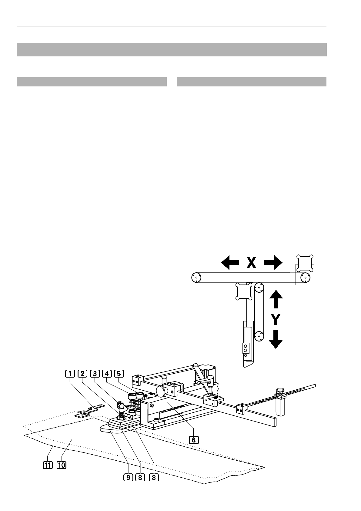
Contour guide, Fig. 5:
The contour guide 5 is the guide for the lower cloth
layer. It is movable in two directions (X/Y). While the
two trousers components are transported to the sewing
unit, the contour guide automatically controls the shape
of the contour in accordance with the presetting. In addition, a reduction of the seam from wide to narrow step
width can be integrated in the automatic contour control.
The two trousers components a and b are blown
to the stop pins 9 of the contour guide using compressed air. If required, the cloth clamp 8 lowers at the
start of the sewing process and fixes the two trousers
components additionally for a freely selectable distance
along the hem to prevent the trousers components from
leaving the contour when the cloth thickens (e.g. pocket
fly).
The deflection plate 6 prevents the pockets from
being caught in the contour guide during the transport.
The following settings are possible for the contour
guide:
•The air pressure for blowing the trousers components to the stop pins 9 of the contour guide can
be set at the throttle 2.
• The setting of the two handwheels 3 and
depends on the material thickness of the cloths to
be processed.
• Use the handwheel 3 to set the distance between the center tab and the baseplate of the contour guide.
Closing Seam Machine 1282-4 Working Instructions
Fig. 5
This setting ensures the easy gliding of the trou-
sers components through the contour guide and
prevents the cloth contour from overturning at the
stop pins.
• Use the handwheel 4 to set the distance of the
cover plate that holds the deflection plate 6 to
the center tab 7.
Cloth guide, Fig. 5:
To allow a seam to be sewn in tailor quality, the system can be equipped optionally with an additional cloth
guide1 for the line-up of the front trousers component.
This feature is available only in connection with the
optional pneumatic rule guide.
4
Fig. 5
- 6 -
Page 16
Closing Seam Machine 1282-4 Working Instructions Beisler Automated Sewing Equipment
Functions of the machine
B.2
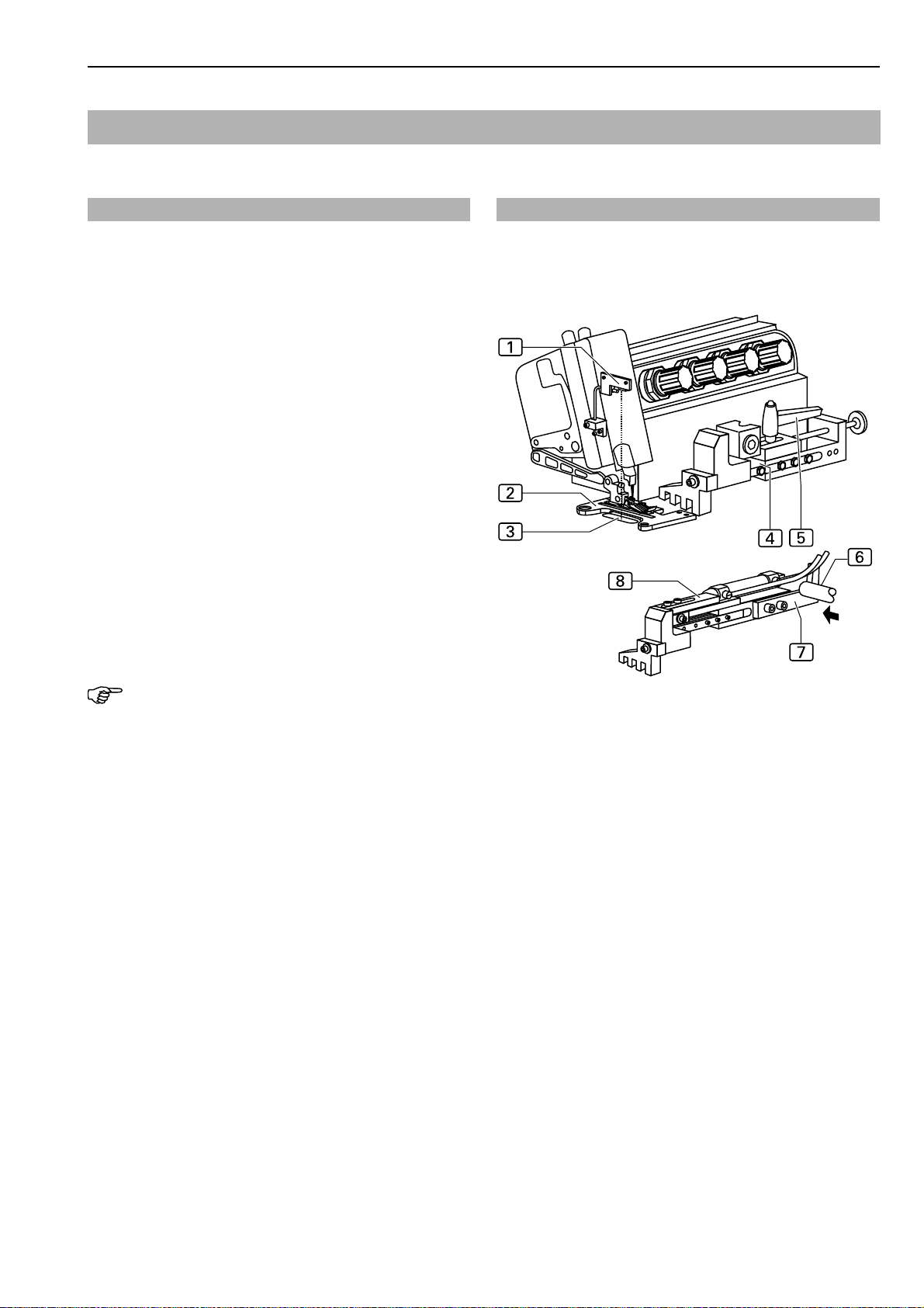
B.2.3 Transport and sewing
Sewing head, Fig. 6:
The machine can be equipped with either a narrow or
a wide sewing unit 2. The seam width is determined
by the width of the pressure foot of the sewing unit and
by the setting of the rule stop 7.
The standard version of the system comprises the manually set rule stop 4 to ensure a constant seam
width throuhout the entire length of the sewing piece.
The pneumatically controlled rule guide 8 allows
a tapered seam width by controlling the contour guide advance in the direction of Y using the shaft
and the catch 7.
The photocell 1 at the sewing head controls the
sewing start. When the reflection of the light beam on
the reflective area 3 is interrupted by the cloth material, the pressure foot lowers. Depending on the preset start mode, the sewing process now starts fully automatically or must be started manually.
The curve which the contour guide travels for controlling
the closing seam is calculated by the program control,
unit using the input X/Y values (see Section D, Programming Instructions).
Fig. 6
Fig. 6
6
NOTE - Reflective film
The reflective area 3 of the photocell must not be
damaged as otherwise a failure of the sewing unit will
occur.
- 7 -
Page 17

Beisler Automated Sewing Equipment
Functions of the machine
B.2
Closing Seam Machine 1282-4 Working Instructions
Fig. 7/8
Transport unit, Fig. 7:
The transport unit 1 consists of the puller 4 and the
roller unit 2. The roller unit picks up the trousers components 3 from the sewing head transport and transports them along the worktable edge to the stacker
(Fig. 8).
The puller adapts its rotating speed correspondingly
to ensure that the cloth contour is guided at the rule
stop.
If the sewing piece moves away from the rule stop, the
puller reduces its rotating speed so that the sewing piece is pulled towards the rule stop.
When the sewing piece is moved too close to the rule
stop, the rotating speed of the puller is increased.
To improve the gliding of the trousers components, the
puller area has six compressed-air nozzles 5 in the
working plate. The compressed air blows against the
trousers components from below to create an air cushion that reduces friction.
Stacker, Fig. 8:
The stacker 1 stacks the tucked trousers
components.
Fig. 7
Fig. 8
- 8 -
Page 18

Closing Seam Machine 1282-4 Working Instructions Beisler Automated Sewing Equipment
Functions of the machine
B.2
B.2.4 Switches
The closing seam machine is equipped with three different types of switches:
• Emergency switch for stopping a sewing program,
• supply switch for current,
• control switches for controlling the machine operation.
Emergency switch
Program stop switch
When the program stop switch 1 is pressed, all machine movements and the sewing process are stopped
immediately.
The switch engages when pressed. Rotating the switch
in the clockwise direction will unlock the switch, and
it moves back to its original position.
The control program performs a reset.
Supply switches
Main switch
The main switch 2 is used to turn the power supply
of the machine on or off. For safety reasons, the machine must be turned off using the main switch when
it is standing still for an extended period; in this case,
all functional units are deactivated. The main switch
also serves as an additional emergency off switch.
Fig. 9
Control switches
Pedal for machine operation
The pedal 3 has two functions: It controls the machine
operation gradually and it can be used to change the
rotating speed of the sewing motor or the sewing speed
of the sewing unit in twelve stages.
Kneeswitch for machine operation
The kneeswitch 4 is used to start fully automatic
machine operation.
Reset switch
The reset 5 is used to restart the insertion process.
If the lower ends of the trousers components are not
clamped correctly into the guide clamp, actuating the
catch will open the guide clamp; when the reset switch
is pressed, the insertion process restarts.
Fig. 9
- 9 -
Page 19
Beisler Automated Sewing Equipment
Functions of the machine
B.2
Closing Seam Machine 1282-4 Working Instructions
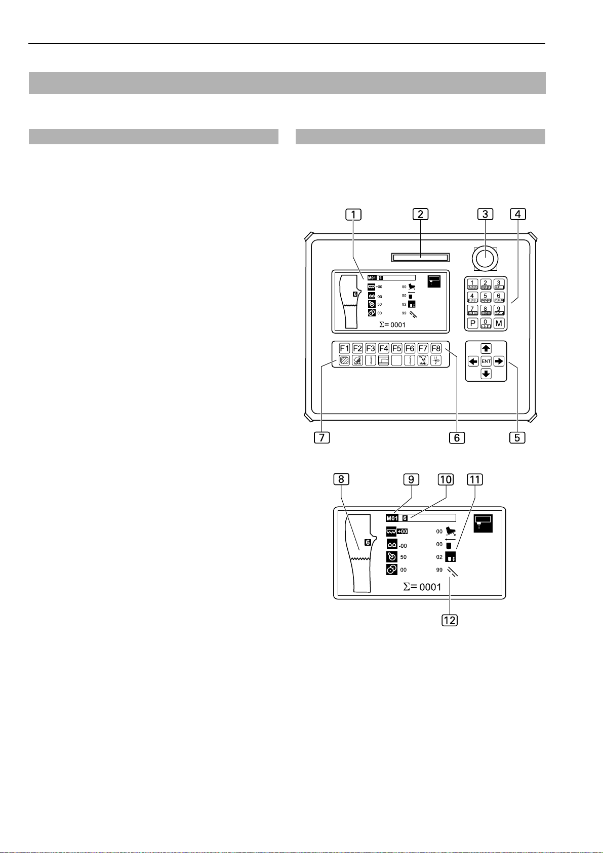
B.2.5 Operating panel
Display
During the operation of the machine, the display
shows the values of the selected sewing program. If
menus were requested, the menu symbol or the corresponding parameters of the function are displayed.
Display
8
Symbol of seam structure of first seam
9
Description of sewing program (a sewing program
may consist of several seams)
a
Seam number of sewing program
b
Symbol of an enabled sewing function. The sym
bol is displayed inverted.
c
Symbol of a disabled sewing function for the
selected seam. The symbol is displayed black
against a bright background.
Memory card slot
The memory card is the medium for storing the bakkup copies of all program control data. Programs can
be copied to and stored on the memory card and reloaded into the machine control when required.
2
Fig. 10
Fig. 10
1
Program stop switch
If the program stop switch 3 is pressed during the
operation of the machine, all machine movements and
the sewing process are stopped.
Numeric keypad
The numeric keypad 4 is used to enter all changeable number values.
By pressing the M key , you can request the desired sewing programs.
By pressing the P key , you can request submenus, confirm inputs and exit the programming mode.
Arrow keys
By pressing the UP or DOWN arrow key 5, you can
move the cursor in the selected menu one line up or
down.
By pressing the RIGHT or LEFT arrow key, you can
mark the desired parameter in the selected menu using
the cursor or browse forward or backward if the parameter list consists of several pages.
Function keys
You can use the function keys 6 to request the menus for setting or changing machine functions on the
selected level.
Symbol bar
The symbol bar 7 indicates menus that can be requested directly from the start menu using the function
keys.
All other functions of the machine can be set or changed by selecting the corresponding menus on the different program levels. The corresponding symbols
appear on the display of the operating panel.
- 10 -
Page 20

Closing Seam Machine 1282-4 Working Instructions Beisler Automated Sewing Equipment
Operation
B.3
B.3.1 Safety instructions for operation
Machine operation
WARNING - Machine operation intervention!
The machine is driven by electric motors and by compressed air. Any attempt to stop the moving parts of
the machine or to tamper with the movements by hand
may cause severe injuries.
• Keep hands away from machine during machine
operation!
• During the sewing process, keep hands away from
the operating range of the needle!
• If a failure is encountered during machine operation, press the program stop switch immediately!
Work clothing:
CAUTION - Unsuited work clothing!
The moving parts of the machine may catch and draw
in loose clothing which may cause severe injuries.
• When operating the machine, do not wear wide or
open clothing!
• Make sure that sleeves are tight-fitting and properly
closed!
- 11 -
Page 21
Beisler Automated Sewing Equipment
Operation
B.3
Closing Seam Machine 1282-4 Working Instructions
B.3.2 Preparing the machine
Prior to the production start, check the supply connections,
connect the machine to the compressed air and power
supply systems and prepare the sewing head.
1. Insert needle, pass top and bottom thread through
needle (see working instructions of sewing head manufacturer or supplier).
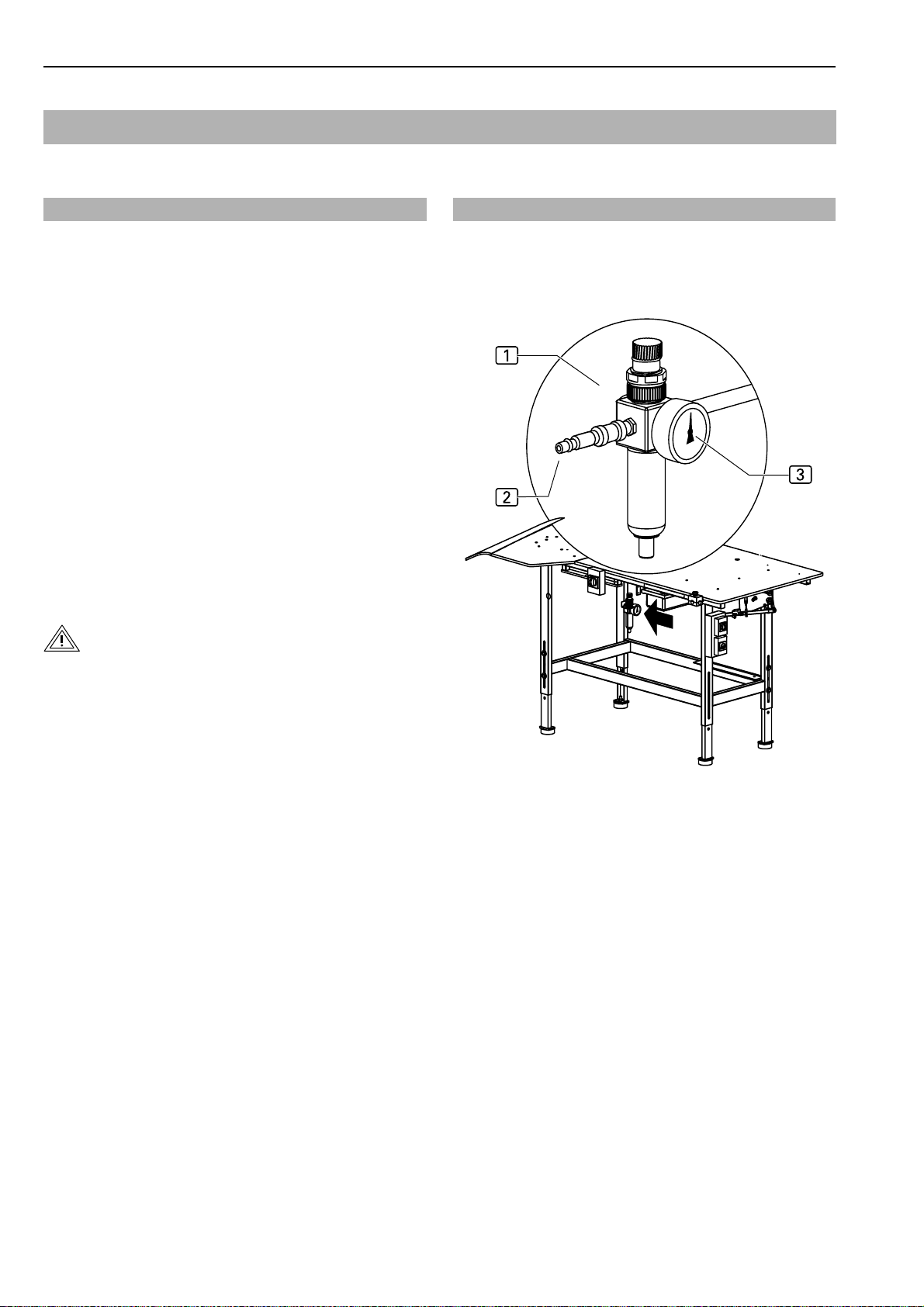
2. Fig. 9: Connect machine to compressed air supply by
inserting the plug-in connector 2 of the compressed
air supply hose into the compressed air receptacle in
the operating room. The pressure of the compressed
air is reduced to the required operating pressure of 6
bar by a pressure reducer 1. Check manometer
to see if the correct operating pressure is set. The
pressure reducer is installed at the side mounting wall
of the worktable.
3. Connect machine to power supply system.
WARNING - Electric shock!
3
Fig. 11
Fig. 11
Contact with current-carrying components may cause
a lethal electric shock. Check plug and cable before
connecting machine to power supply system.
• Do not use damaged plugs, sockets or cables to
connect the machine to the power supply system!
• The machine is connected to a power source of 230
V ±10 % at 50/60 Hz or 1 15 V ±10 % at 60 Hz (see Section C, Specifications).
• Before connecting the machine to the power supply
system, check to see if the ratings of the power supply system in the operating room correspond with the
ratings on the nameplate at the rear of the machine.
• If the ratings for voltage (V) and maximum current (A)
do not match, the machine must not be connected.
• Insert the grounding plug into a properly grounded and
fused power socket.
• Make sure that the power supply cable is not subject
to tensile or pressure forces.
.
4. Turn machine on by moving main switch to position I.
The display shows that the program control has not
been activated.
5. Power up program control by pressing program stop
switch. During this time, the display shows "RESET".
6. Unlock program stop switch (see Section B.2.4).
The machine is ready for operation.
- 12 -
Page 22
Closing Seam Machine 1282-4 Working Instructions Beisler Automated Sewing Equipment
Operation
B.3
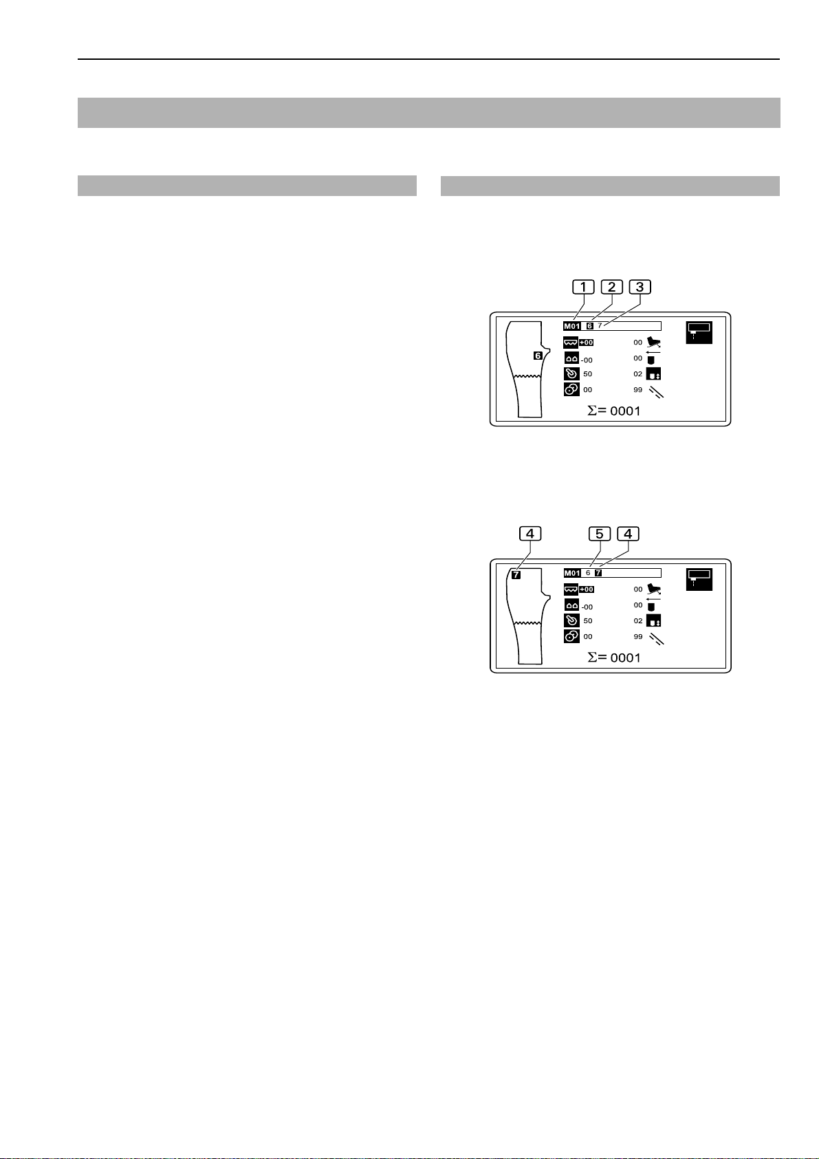
B.3.3 Selecting the sewing program
After the machine has been turned on and the control program has been activated, the sewing program that had
been selected last is set.
Sewing programs 1 are stored in the memory (M). The
program control memory can store up to 20 sewing programs (M 01-M 20).
Fig. 12: Up to two seams with corresponding seam numbers2 and 3 are assigned to each sewing program1. The two seams differ in their control functions
(see Section D, Programming Instructions) and can be
sewn either in automatic or manual change.
Depending on the production type of the sewing pieces,
various sewing programs for the program have been preprogrammed at the factory.
Programs for trousers production:
M 01 Side seam with braid pocket
M 02 Side seam with pocket in side seam
M 03 Side seam with wing pocket
M 04 Crotch seam
M 05 Side seam with pocket in side seam
M 06 Side seam with seam interruption before hem (avai-
lable only for systems with additional thread cutter
feature)
Fig. 12/13
Fig. 12
Fig. 13
Programs for jacket production:
M 01 Main seam
M 02 Seam interruption by stitch counter
M 03 Seam interruption by photocell
M 04 Thread cutting at beginning of seam, sewing start
in sewing piece
The seams of a sewing program can be sewn either in
automatic or manual change.
1. Select sewing program at operating panel.
The sewing programs M01- M09 can be selected directly by entering the seam numbers at the numeric
keypad. The sewing programs M10- M20 are selected
from the memory:
• Press key.
Select sewing program number, e.g. 11:
• Press and keys.
Confirm selection:
• Press & key.
2. Change seam number of desired seam in direct
access.
Move cursor to seam number:
• Press 1 or 0 key.
Fig. 13: Display for seam number selection:
1
3
Passive seam number
Active seam number
- 13 -
Page 23

Beisler Automated Sewing Equipment
Operation
B.3
Closing Seam Machine 1282-4 Working Instructions
Programs with one-digit program numbers (M01 - M09)
can be selected directly using the numeric keypad:
e.g. V = Program M06
To select two-dogit program numbers (M10-M20):
• Press the key
To select the number of the sewing program, e.g.10:
• Press the and keys
B.3.4 Manual sewing
The function "Manual sewing" is used for testing the sewing head and the sewing unit.
Request manual sewing by direct access:
Activate stacker manually by direct access:
• Press key.
7
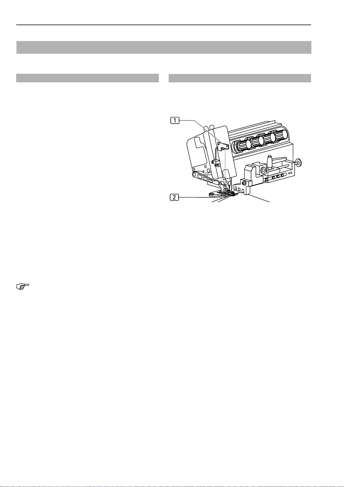
B.3.6 Threading Fig. 14
This function is used for easy threading. The mechanical
system of the sewing unit is locked. The pressure foot is
lowered, the transport unit is raised.
Prepare the sewing unit for threading:
• Press key.
The display shows the symbol for Threading 1 next
to the description of the sewing program.
Fig. 14
• Press key.
8
The display shows the symbol for Manual seam:
9
Manual sewing is controlled using the footswitch.
Pressing the right side of the footswitch starts the sewing
process. The sewing speed can be controlled in twelve
stages, depending on the pressure exerted. The higher
the pressure, the higher the speed.
NOTE - Program reset!
After completion of a test, the sewing program must be
restarted by pressing the reset key at the operating panel.
B.3.5 Operating the stacker
The stacker can be operated manually independent of the
automatic machine cycle. If this function is enabled, the
stacker performs a stacking run.
- 14 -
Page 24

Closing Seam Machine 1282-4 Working Instructions Beisler Automated Sewing Equipment
Operation
B.3
B.3.7 Line-up and alignment of sewing pieces
1. Fig. 15: Place trousers components on top of each
other with the seams being flush. The sequence
depends on the preselected sewing progrem.
2. Make sure that the guide clamp is at the line-up
position (right side of working plate).
3. Push the ends of the two trousers components from
the front into the needle clamp 1 of the guide clamp
and push the clamp down.
If the machine is equipped with the optional cloth transfer machine component, the ends of the trousers components are pushed into the cloth transfer 3 from the
front.
The cloth transfer transfers the trousers ends to the
guide clamp 2, where the needle clamp fixes them
automatically.
4. Line the trousers components up at the contour guide. Place the lower trousers component 5 over the
baseplate6and under the center tab 8 and the
upper trousers component 7 over the center tab
8
of the contour guide. Push both trousers components 9 of the contour guide all the way to the
stop.
If equipped with a contour guide for tailor quality, the
front trousers component must be pushed into the cloth
guide4 all the way to the stop.
Depending on the seam, the rear trousers component
is lined up above or below the cloth guide.
5. Line up the hip-side end of the trousers components
at the rule stop c and push it under the pressure
footb all the way to the needle.
Fig. 15
Fig. 15
NOTE - Resetting the insertion process!
If the insertion process is to be cancelled, pull the trousers components away from the light beam of the photocell
a
. When the photocell recognizes bright light, the ma-
chine cycle is interrupted.
- 15 -
Page 25
Beisler Automated Sewing Equipment
Operation
B.3
Closing Seam Machine 1282-4 Working Instructions
B.3.8 Starting machine cycle
A machine cycle can be started in three different sequences (mode 00, mode 01, mode 02). The factory default is mode 00.
Controlling machine cycle in mode 00, Fig. 16:
Mode 00 starts a fully automatic machine cycle that is
controlled by the photocell.
1. Insert the trousers components into the guide clamp
and line them up over the contour guide at the pressure foot.
2. As soon as the cloth material interrupts the light beam
of the photocell at the reflective film 1, the machine
cycle starts. The photocell responds with a delay whose
duration can be set individually using the program
control.
• The trousers components are routed along the guide rail to the contour guide.
• The contour guide controls the routing of the seam.
• The sewing unit sews the overlapping components to each other.
•The sewing process is completed as soon as the
trousers components have passed the reflective
film of the photocell.
• The roller unit pulls the sewing piece from the
worktable to the stacker.
•The stacker stacks the trousers components.
Fig. 16
Fig. 16
NOTE - Supplying sewing pieces!
As soon as the guide clamp has returned to the insertion station, the next machine cycle can be started.
- 16 -
Page 26

Closing Seam Machine 1282-4 Working Instructions Beisler Automated Sewing Equipment
Operation
B.3
Fig. 17
Controlling machine cycle in mode 01:
Mode 01 starts a combination of manually controlled
seam and subsequent automatic machine cycle that is
controlled using the pedal.
1. Insert the trousers components into the guide clamp
and line them up over the contour guide at the pressure foot.
2. Pressing the right side of the pedal 2 starts the se-
wing process. The sewing speed can be controlled in
twelve stages, depending on the pressure that is exerted. The higher the pressure, the faster the speed.
Using this control, the seam can be controlled manually
for complicated sewing stages.
3. The automatic machine cycle can be started by pres-
sing the left side of the pedal 1 at any position of the
seam.
• The remaining seam dist ance is effected along the
guide rail to the contour guide.
• The contour guide controls the further routing of
the seam.
•The sewing unit sews the overlapping components to each other.
• The sewing process is completed as soon as the
trousers components have passed the reflective
film of the photocell.
• The puller pulls the sewing piece from the workt able to the stacker.
• The stacker stacks the trousers components.
Fig. 17
NOTE - Supplying sewing pieces!
As soon as the guide clamp has returned to the insertion station, the next machine cycle can be started.
- 17 -
Page 27

Beisler Automated Sewing Equipment
Operation
B.3
Closing Seam Machine 1282-4 Working Instructions
Fig. 18
Controlling machine cycle in mode 02:
Mode 02 starts a fully automatic machine cycle that is
initiated using the kneeswitch.
1. Insert the trousers components into the guide clamp
and line them up over the contour guide at the pressure foot until the photocell recognizes the cloth and
the pressure foot is lowered.
2. Fig. 18: As soon as the kneeswitch 2 is pressed, the
fully automatic machine cycle starts.
• The trousers components are routed along the guide rail to the contour guide.
• The contour guide controls the routing of the seam.
• The sewing unit sews the overlapping components to each other.
•The sewing process is completed as soon as the
trousers components have passed the reflective
film of the photocell.
•The puller pulls the sewing piece from the workt able to the stacker.
•The stacker stacks the trousers components.
NOTE - Supplying sewing pieces!
As soon as the guide clamp has returned to the insertion station, the next machine cycle can be started.
Fig. 18
B.3.9 Resetting the insertion process
The function "Resetting the insertion process" applies only
to those procedural steps that are effected immediately
at the insertion station before the automatic cycle begins:
• inserting trousers components into guide clamp,
• inserting trousers components into optional cloth transfer.
Machines equipped with guide clamp:
1. Open needle clamp manually, push guide clamp catch
to right.
2. Remove sewing piece from needle clamp and
reposition.
Machines with cloth transfer:
1. Press reset key 1.
2. The cloth transfer holding clamp opens, the sewing
pieces can be removed and reinserted.
3. If the sewing pieces were already transferred to the
guide clamp, push guide clamp catch to left. The needle
clamp opens, the sewing pieces can be repositioned
or removed.
- 18 -
Page 28

Closing Seam Machine 1282-4 Working Instructions Beisler Automated Sewing Equipment
Operation
B.3
B.3.10 Moving machine to zero position
Prior to starting production, after machine tests or after
corrections to sewing programs, the machine must be returned to zero position for starting the machine cycle:
1. Press program stop switch.
2. Unlock program stop switch.
(See also Section B.3.11, Stopping a sewing program)
B.3.11 Stopping a sewing program
1. Press program stop switch.
When this switch is pressed, all machine movements
and the sewing process are stopped immediately . The
switch engages when pressed.
To restart the machine after a program stop, all functions
must be reset, and the machine must be returned to zero
position by unlocking the program stop switch.
B.3.12 Turning the machine off
For extended work intermissions, the machine must be
turned off completely.
1. Turn power supply off by moving main switch to
position 0.
2. Disconnect machine from compressed air supply.
2. Unlock program stop switch.
Slightly rotate switch in the clockwise direction. The
switch returns to its original position.
The control program performs a reset.
- 19 -
Page 29

Beisler Automated Sewing Equipment
Operation
B.3
Closing Seam Machine 1282-4 Working Instructions
B.3.13 Periodic cleaning of the machine
The machine must be cleaned after large production series
or at least once a day, whichever occurs first.
CAUTION - Danger of injuries!
If the machine is put in motion accidentally, persons
in its direct vicinity may be caught by moving parts
which may cause injuries.
Prior to any cleaning work, disconnect the machine
from the power supply!
• Turn the machine off using the main switch.
• Remove the power plug from the socket and protect it from accidental reconnection.
Periodic cleaning:
1. Remove fabric residues.
2. Using compressed air, blow off dust and thread residues at the sewing head, at the working plate, at the
guide rail and at the contour guide.
3. Empty waste container . Remove waste container
from container head 1 by rotating container in the
clockwise direction.
4. Install container to head by rotating it in the counterclockwise direction.
2
Fig. 19
Fig. 19
- 20 -
Page 30

Closing Seam Machine 1282-4 Working Instructions Beisler Automated Sewing Equipment
Section C
Service Instructions
- 1 -
Page 31

Beisler Automated Sewing Equipment
Closing Seam Machine 1282-4 Working Instructions
Service Instructions
Section C
Contents
C.1 Delivery of the machine
C.1.1 Packaging......................................................................................................................................................3
C.1.2 Scope of delivery...........................................................................................................................................3
C.2 Storage and location requirements ...........................................................................................................4
C.2.1 Floor quality...................................................................................................................................................4
C.2.2 Interior climate...............................................................................................................................................4
C.2.3 Floor space required .....................................................................................................................................4
C.2.4 Supply connections.......................................................................................................................................4
C.3 Start-up.........................................................................................................................................................5
C.3.1 Machine table alignment ...............................................................................................................................5
C.3.2 Compressed air connections ........................................................................................................................6
C.3.3 Sewing unit....................................................................................................................................................6
C.3.4 Connecting the machine to the power supply ..............................................................................................7
C.3.5 Safety check..................................................................................................................................................7
C.4 Operation and shut-down...........................................................................................................................8
C.4.1 Working with the machine.............................................................................................................................8
C.4.2 Machine shut-down.......................................................................................................................................8
C.5 Maintenance.................................................................................................................................................9
C.5.1 Inspection......................................................................................................................................................9
C.5.2 Cleaning ........................................................................................................................................................9
C.5.3 Service ........................................................................................................................................................10
C.5.4 Repairs ........................................................................................................................................................11
Operating panel replacement................................................................................................................. 11
Contour guide toothed belt replacement................................................................................................12
Transport unit toothed belt replacement ................................................................................................13
Stepper motor toothed belt replacement................................................................................................13
Puller toothed belt replacement .............................................................................................................13
Roller unit toothed belt replacement ......................................................................................................14
Guide clamp cable replacement ............................................................................................................15
C.5.5 Machine set-up............................................................................................................................................16
Guide rail adjustment .............................................................................................................................16
Setting the contour guide .......................................................................................................................17
Setting the rule stop ...............................................................................................................................19
Setting the standard rule stop ................................................................................................................19
Setting the automatic rule stop with catch .............................................................................................20
Adjusting the seam control photocell .....................................................................................................21
Adjusting the contour guide control photocell ........................................................................................22
Adjusting the photocells .........................................................................................................................22
Setting the puller lowering position and pressure ..................................................................................23
Setting the distances of the transport rollers and of the downrollers to the working plate.....................23
Adjusting the stacker motion ..................................................................................................................24
Setting the knop positions ......................................................................................................................24
Setting the motion speed .......................................................................................................................24
Coordination of the motion .....................................................................................................................24
Regulating the pneumatic air cushion
Setting the pressure of the automatic cloth clamp
Installation stepper motor.......................................................................................................................26
Adjusting switches on the PCB ..............................................................................................................26
C.6 Specifications ............................................................................................................................................ 27
....................................................................................................
.................................................................................
25
25
- 2 -
Page 32

Closing Seam Machine 1282-4 Working Instructions Beisler Automated Sewing Equipment
Delivery of the machine
C.1
C.1.1 Packaging
The machine is delivered in a solid packaging box on a
pallet. All packaging materials can be separated and
reused.
• Pallet made of pine wood
• Packaging box made of plywood / transport carton
• Polyethylene film (PE)
NOTE - Shipping braces!
During shipping, moving machine parts are protected with
shipping braces (cable ties). The positions of all parts fitted
with shipping braces are marked with red labels.
After the machine has been installed and aligned, the
shipping braces must be removed.
NOTE - Damages in transit!
If any damage presumably caused by incorrect transport
is found when the machine is unpacked, please contact
your supplier immediately.
C.1.2 Scope of delivery
The machine is delivered in an operative condition. The
scope of delivery comprises:
Closing seam machine with sewing head
• The machine is equipped with several customerspecific accessories. For checking the exact layout, the information on the delivery note is
authoritative.
• Service kit with machine oil.
Operating panel and program control:
• Preinstalled (ready-for-use) operating panel.
• Memory card with factory-programmed standard
sewing program.
Technical documents:
• Operating instructions.
• Service instructions.
• Programming instructions.
- 3 -
Page 33

Beisler Automated Sewing Equipment
Storage and location requirements
C.2
Closing Seam Machine 1282-4 Working Instructions
C.2.1 Floor quality
The floor of the room where the machine is to be installed must have a sufficient surface strength. The location
of the machine must be free of vibrations.
If several machines are to be installed in one room, the
static load bearing capacity of the ceiling must be
considered.
Weight:
• Machine with accessories approx. 200 kg
C.2.2 Interior climate
Climatic requirements for the operating room:
The machine must only be stored or operated in closed
operating rooms.
• Room temperature +10 °C to +45 °C
• Relative humidity 80 % max.
C.2.3 Floor space required
C.2.4 Supply connections
The machine requires on-site power and compressed air
sources.
Power connection:
The power supply of the machine requires a properly
grounded power connection with:
• Grounding plug 230 V ± 10 %, 50/60 Hz
or
• Safety plug 115 V ± 10 %, 60 Hz
• Fusing 16 A
NOTE - Peak voltages!
The correct function of the machine requires that the power
system supplies a constant current. Peak voltages may
particularly impair the stability of the program control.
Compressed air supply:
The on-site compressed air supply system must meet the
following requirements:
• Operating pressure 6 bar
• Compressed air quality oil-free
• Compressed air consumption 4.16 NL/AT
For operation during production and for service works, the
machine must be freely accessible from all sides. On all
sides, there must be a minimum clearance of 1 m.
Machine dimensions:
• L x W x H 2700 x 1200 x 1900 mm
NOTE - Electromagnetic interference!
The machine must not be installed in the immediate vicinity
of devices or electrical components (e.g. transformers)
generating a strong magnetic field as otherwise the correct function of the program control may be impaired.
- 4 -
Page 34

Closing Seam Machine 1282-4 Working Instructions Beisler Automated Sewing Equipment
2
2
3
1
St art-up
C.3
C.3.1 Machine table alignment
After the machine has been installed at the desired location, the machine table must be aligned:
• Set machine table to required height.
• Align machine table horizontally on all sides.
Setting table height:
1. Fig. 1: Lift machine: Connect lifting device to lift points
(arrows) below the crossmembers. If the machine is
equipped with optional transport rollers, release brakes before lifting.
2. Fig. 2: Loosen lockscrews 2 on all guide rails.
3. Pull table legs 3 out to the desired length and retighten lockscrews 2.
4. Lower machine to floor.
Horizontal positioning of the machine table:
1. Place bubble level onto working plate.
2. Fig. 2: Loosen table leg lock nuts 1.
3. Align machine table horizontally on all sides by raising
or lowering table legs as required.
4. Retighten table leg lock nuts.
Fig. 1/2
Fig. 1
NOTE - Shipping braces!
Before the machine is connected to the energy supply
sources, all shipping braces must be removed.
• Cut off cable ties.
• Remove labels.
Fig. 2
- 5 -
Page 35

Beisler Automated Sewing Equipment
St art-up
C.3
Closing Seam Machine 1282-4 Working Instructions
C.3.2 Compressed air connection
The compressed air connection is preinstalled on the
machine. It comprises the following components:
• Fig. 3: Pressure reducer 2 with manometer
and water separator 5,
• Quick-disconnect coupling 1 for pressure hose.
The pressure reducer is mounted to the left rear leg of the
worktable.
Connecting the machine to the compressed air supply system:
1. Connect pressure hose plug to on-site terminal unit.
2. Open on-site compressed air supply.
3. Set pressure reducer to a machine operating pressure
of 6 bar by rotating pressure reducer knob 3 and read
value on manometer 4:
• T o increase pressure, rotate in clockwise direction,
•To reduce pressure, rotate in counter-clockwise
direction.
C.3.3 Sewing unit
4
Fig. 3 / 4
Fig. 3
Prior to connecting the machine to the power supply system and performing a test run, the condition of the sewing unit must be checked.
• Fig. 4: Retighten retaining screws 1 and 2 of the
sewing unit stitch plate.
Fig. 4
- 6 -
Page 36

Closing Seam Machine 1282-4 Working Instructions Beisler Automated Sewing Equipment
St art-up
C.3
C.3.4 Connecting the machine to the power supply
The power cable and the power plug are preinstalled on
the machine. The pedal and the knee switch for controlling
the machine operation are installed as well.
Connecting the machine to the power supply system:
1. Keep pedal for controlling the machine operation ready
at the front side of the machine.
2. Establish power supply connection.
WARNING - Electric shock!
Contact with current-carrying components may cause
a lethal electric shock. Check plug and cable before
connecting machine to power supply system.
• Do not use damaged plugs, sockets or cables to
connect the machine to the power supply system!
• The machine can be connected to any of the following
power supply systems:
230 V ±10 % at 50/60 Hz
115 V ±10 % at 60 Hz, lead assignment:
Ground = ground
N = R
1
R = R
• Before connecting the machine to the power supply
system, check to see if the ratings of the power supply system in the operating room correspond with the
ratings on the nameplate at the rear of the machine.
• If the ratings for voltage (V) and maximum current (A)
do not match, the machine must not be connected.
• Insert the grounding plug into a properly grounded and
fused power socket.
• Make sure that the power supply cable is not subject
to tensile or pressure forces.
• Route the power supply cable in a way that ensures
free access to and around the machine.
2
C.3.5 Safety check
Before the machine is released for operation, all safety devices must be checked for their correct operation.
CAUTION - Danger of injuries!
The safety devices protect the operating and service
personnel while working on or with the machine.
If the safety devices are fully or partially inoperative,
the machine must not be started up.
Perform safety check:
1. The main switch also serves as an emergency off
switch. To check the function of this switch, turn the machine on, start a machine cycle and turn the machine
off during the tucking process using the main switch.
All operational movements of the contour guide, of the
puller and of the sewing head must stop, and the program control must switch off.
2. Check the function of the program stop switch. Start
a machine cycle and press the switch. All operational
movements of the contour guide, of the puller or of the
sewing head must stop.
3. Unlock the program stop switch. The program control
starts a reset, and the clamp must return to its start
position.
The machine is ready for operation.
NOTE - Works to the electrical system!
Works to the electrical system of the machine must only
be carried out by qualified and authorized expert personnel.
Tampering with the machine without authorization makes
the warranty void.
- 7 -
Page 37

Beisler Automated Sewing Equipment
Operation and shut-down
C.4
Closing Seam Machine 1282-4 Working Instructions
C.4.1 Working with the machine
Factory settings
The machine has been preprogrammed at the factory with
six sewing programs (M 01- M 06).
Programs for trousers production:
M 01 Side seam with braid pocket
M 02 Side seam with pocket in side seam
M 03 Side seam with wing pocket
M 04 Crotch seam
M 05 Crotch seam with tailor quality
M 06 Side seam with seam interruption before hem
(available only for systems with additional
thread cutter feature)
Programs for jacket production:
M 01 Main seam
M 02 Seam interruption by stitch counter
M 03 Seam interruption by photocell
M 04 Thread cutting at beginning of seam, sewing
start in sewing piece
The sewing programs are so powerful that they can be
used for production.
They are furthermore perfectly suited for training operating personnel and can be used as a template for programming customer-specific sewing programs.
For details about the programming of sewing programs,
please see Section D of the working instructions.
C.4.2 Machine shut-down
If the machine is to be shut down, it must be disconnected from all energy supply sources.
Disconnecting the machine from the power supply
system:
1. Turn machine off using main switch. Move switch to
position "0".
2. Remove power plug from socket and protect it against
accidental reconnection.
Disconnecting the machine from the compressed air
supply system:
1. Shut off on-site compressed air system.
2. Remove compressed air hose plug from terminal unit.
NOTE - Dust-proof protection!
If the machine is to be shut down for an extended period
of time, it should be covered with a plastic tarpaulin.
- 8 -
Page 38

Closing Seam Machine 1282-4 Working Instructions Beisler Automated Sewing Equipment
Maintenance
C.5
WARNING - Electric shock!
Contact with current-carrying components may cause
a lethal electric shock
If the machine is put in motion accidentally, persons
in its direct vicinity may be caught by moving parts
which may cause injuries.
Prior to any service, cleaning or maintenance works,
disconnect the machine from the power supply
system!
• Turn the machine off using the main switch.
• Remove power plug from socket and protect it
against accidental reconnection.
• If the power supply is not required for repair or setup work, the machine must be disconnected from
the power supply system.
C.5.1 Inspection
The machine must be inspected annually.
The inspection comprises particularly the following items:
• safety devices of the machine,
• operativeness of the program control,
• correct function of inputs and outputs.
C.5.2 Cleaning
The machine must be cleaned after large production series, or at least once a day, whichever occurs first.
Cleaning the machine surfaces:
1. Disconnect machine from power supply system.
2. Remove fabric residues.
3. Using compressed air, blow off dust and thread residues at the sewing head, at the puller, at the working
plate and at the contour guide.
4. Wipe machine parts dry using a dry, clean cloth.
NOTE - Plastic surfaces!
Some parts of the machine surfaces are made of plastic
materials. Solvents may dissolve plastics and make them
unusable.
Do not clean the machine surfaces (particularly the operating panel) with cleaning agents that contain solvent.
- 9 -
Page 39

Beisler Automated Sewing Equipment
Maintenance
C.5
Closing Seam Machine 1282-4 Working Instructions
C.5.3 Service
The following service works must be carried out in weekly
intervals.
Oiling the rails:
1. Disconnect machine from power supply.
2. Wipe guide clamp guide rail using a clean, oil-saturated
cloth.
3. Wipe contour guide X and Y rail using a clean, oil-saturated cloth.
NOTE - Oil supply!
The scope of delivery comprises 0.25 l of oil. When this
oil is used up, you can order the special machine oil for
service from the manufacturer or supplier of the
machine.
Emptying the water separator:
1. Disconnect machine from power supply.
2. Fig. 5: Drain water at pressure reducer water separator
into suited container.
Press button 1 at pressure reducer collector and keep
pressed until all the water has been drained.
Fig. 5
Fig. 5
Sewing head service:
NOTE - Sewing head service instructions!
For information about service of the sewing head, please refer to the working instructions of the sewing head.
- 10 -
Page 40

Closing Seam Machine 1282-4 Working Instructions Beisler Automated Sewing Equipment
Maintenance
C.5
C.5.4 Repairs
Any repairs to the machine must only be carried out by:
• authorized Technical Service,
• personnel that has been instructed about the setting
up and maintenance of the machine on the occasion
of a training by the supplier or manufacturer of the
machine.
Use only original spare parts for installing or replacing
machine components.
Manufacturer and supplier will not be held responsible for
spare parts from third parties.
NOTE - Programming instructions!
Repairs require that machine components carry out their
individual movements and that the machine movements
are tested. These functions are controlled on level 1 of the
service menu.
For the necessary instructions, please refer to the programming instructions.
Operating panel replacement:
1. Disconnect machine from power supply.
2. Fig. 6: Remove two lock screws 2 and disconnect
interface connector 3.
3. Remove retaining screws 1 from operating panel
bracket.
4. Remove operating panel 5, install new panel and
secure using screws.
5. Connect interface connector to receptacle 4 and secure using two lock screws 2.
Fig. 6
Fig. 6
- 11 -
Page 41

Beisler Automated Sewing Equipment
Maintenance
C.5
Closing Seam Machine 1282-4 Working Instructions
Fig. 7
Contour guide toothed belt replacement:
The two toothed belts for the contour guide stepper motors
(X rail and Y rail) are connected by a belt clamp.
1. Disconnect machine from power supply system.
2. Shift contour guide on X/Y rail manually until the corresponding rail clamp is accessible.
3. Fig. 7: Remove retaining screws 1 of belt cover
at the corresponding pedestal 3 and remove cover.
4 Remove fixing screws 4 of pedestal 3 to release
belt tension.
7. The belt clamp 6 is attached with four screws
tatthe X rail and with three screws 5 at the Y rail to
the stepper motor mounting plate. Remove screws and
remove toothed belt 7.
8. Position new belt onto both pulleys.
9. Align belt 7 with holes at the ends to fixing pins and
secure belt clamp 6 to stepper motor mounting plate
using the screws.
10.T ension belt 7 by shifting pedestal and tightening fixing screws 4. In case of correct tensioning, it must
be possible to depress the center of the belt approx 10
mm until counterpressure is felt. Tighten fixing
screw4.
11.Install pedestal cover.
2
5
Fig. 7
- 12 -
Page 42

Closing Seam Machine 1282-4 Working Instructions Beisler Automated Sewing Equipment
Maintenance
C.5
Fig. 8/9
Transport unit toothed belt replacement:
The transport unit consistst of three units that are each
driven by a toothed belt:
• Stepper motor toothed belt,
• puller toothed belt,
• roller unit toothed belt.
Stepper motor toothed belt replacement:
1. Lower transport unit manually onto workplate (see
Section D.2.1, Program control).
2. Switch machine off.
3. Fig. 8: Release belt tension by removing fixing screw
5
of stepper motor mounting plate.
4. Lift toothed belt up from stepper motor pulley 1 and
then from roller unit 4. For this, the pressure cylinder3 must be removed from the lower mounting. Remove retaining nut 2 and pull scew off the shaft.
5. To install, guide toothed belt over transport pulley linkage and position into shaft drive pulley , then into the
stepper motor drive pulley.
6. To pretension the toothed belt, push plate with stepper motor down and tighten fixing screw. In case of correct tensioning, it must be possible to depress the
center of the belt approx 10 mm until counterpressure is felt.
7. Tighten fixing screw 5.
Puller toothed belt replacement:
1. Lower transport unit manually onto workplate (see
Section D.2.1, Programming Instructions).
2. Switch machine off.
3. Fig. 9: Slacken toothed belt, remove grub screw
at the bearing and push bearing up on spacer
shaft 6.
4. Lift toothed belt up from drive pulley 1 and from the
two rollers 7 and 4 and remove.
5. Install toothed belt to idle roller, then to drive pulley.
6. T o pretension the toothed belt, push bearing downward
on spacer shaft and tighten threaded pin. In case of
correct tensioning, it must be possible to depress the
center of the belt 2 approx 10 mm until counterpressure is felt.
5
Fig. 8
Fig. 9
NOTE - Transport roller alignment!
After toothed belt replacement, the distance between the
puller transport rollers and the working plate must be realigned (see Section C.5.5).
- 13 -
Page 43

Beisler Automated Sewing Equipment
Maintenance
C.5
Closing Seam Machine 1282-4 Working Instructions
Fig. 10
Roller unit toothed belt replacement:
1. Lower transport unit manually onto workplate (see
Section D.2.1, Program control).
2. Switch machine off.
3. Fig. 10: Slacken toothed belt 1 by removing grub
screw4 of bearing 3 and pushing guide fork
5
of two roller units together with spacer
shaft 2 up into bearing.
4. Lift toothed belt off drive roller and idle roller and
remove.
5. To install, position toothed belt onto roller, then onto
bearing drive pulley.
6. To pretension the toothed belt, push bar roller guide
fork with spacer shaft down and tighten threaded pin
at bearing. In case of correct tensioning, it must be possible to depress the center of the belt approx 10 mm
until counterpressure is felt.
NOTE - Transport roller alignment!
After toothed belt replacement, the distance between the
downrollers and the working plate must be realigned (see
Section C.5.5).
Fig. 10
- 14 -
Page 44

Closing Seam Machine 1282-4 Working Instructions Beisler Automated Sewing Equipment
Maintenance
C.5
Fig. 11
Guide clamp cable replacement:
Fig. 11: The guide clamp cable 1 is attached to the guide
clamp rail 2 and to the plate a below the worktable. Belt
tension is ensured by the counterweight 9.
Cable replacement:
1. Fig. 11: A screw secures the eyelet on one end of the
cable4 to the rail. Remove retaining screw 3 from
guide clamp rail 2.
2. Another screw secures the eyelet on the other end of
the cable 6 to the plate a. Remove retaining screw
7
from plate.
3. Remove cable from four deflection rollers 5.
4. Before installation, make sure that the cable is not
twisted or knotted. Secure cable eyelets to rail and to
plate using the screws, then position cable onto rollers.
5. Adjust counterweight 9. Loosen fixing screw 8 and
reposition counterweight on lever. The correct position is reached when the cable is slightly tensioned by
the tensile force of the counterweight; however, the
counterweight must not exert pressure onto the guide
clamp.
6. Tighten fixing screw 8.
7. Set return cylinder b pressure. To increase pressure for setting a higher return speed, rotate knob c in
the counterclockwise direction.
Fig. 11
NOTE - Guide clamp damage!
If the pressure is set too high (return speed to high), the
guide clamp may be damaged due to an impact at the
insertion station buffer.
- 15 -
Page 45

Beisler Automated Sewing Equipment
Maintenance
C.5
Closing Seam Machine 1282-4 Working Instructions
C.5.5 Machine set-up
NOTE - Activating inputs/outputs!
To allow for testing machine movements or interval operation, the individual stages of movement can be activated with the inputs/outputs of the machine control unit (see
programming instructions, Section D.4.3., Service menu
level 1).
Usually, the setting up of the machine is controlled by
parameter values of the sewing programs (special parameters) and the parameter values of the machine control
unit (global parameters). The following mechanical changes may be required additionally to ensure correct seams
with the set parameter values.
Guide rail adjustment:
Fig. 12: The flexible guide rail 4 determines the routing
direction of the guide clamp.
The shape of the guide rail is identical with the contour of
the pieces that are to be sewn 5. The routing is determined by changing the position of the guide shaft 3.
Fig. 12
Fig. 12
Setting the contour:
1. Place trousers component under guide rail and align
hip side with the sewing unit, with the contour guide stop
and with the end at the insertion station.
2. First, set the slightly flat contour at the insertion station. Loosen fixing screws 2 of corresponding clamp
elements 1, shift guide shafts 3 with guide rail to
trousers hem and fix it there by tightening fixing
screw2.
3. Set guide rail finishing curve above the contour guide.
Release clamping element locking lever 6, align guide
rail curve with trousers component and fix it by tightening locking lever.
4. Position pick-up clamp 7. This clamp is used to disengage the trousers components from the guide clamp
just before it reaches the contour guide. The traveling
motion of the guide clamp should occur as late as possible; however, the pick-up clamp should stop the motion in a sufficient distance from the contour guide.
Loosen knurled screw 8, position pick-up clamp at
guide rail and secure it in this position by tightening
knurled screw.
5. Tuck trousers components, check routing of seam and
readjust guide rail if required.
- 16 -
Page 46

Closing Seam Machine 1282-4 Working Instructions Beisler Automated Sewing Equipment
Maintenance
C.5
Fig. 13
Setting the contour guide:
The following can be set at the contour guide:
• material thickness of the cloths,
• the pressure of the compressed air used to blow the
trousers components to the contour guide stop,
• lowering position and pressure to be exerted onto the
upper trousers component,
The setting is to ensure that:
• the sewing pieces can be blown easily to the contour
guide,
• the trousers components glide easily on the worktable
and maintain their position to each other during transport.
Setting material thickness for sewing pieces:
The setting for the material thickness is determined in a
test by presetting the corresponding knurled screw and
by a visual check at the contour guide stop.
Fig. 13: The material thickness is set correctly if:
• a single layer of the cloth can be blown easily to the
contour guide stop 4,
• a double layer of the cloth does not fit in the space
between the baseplate 8 and the center tab
or between center tab and cover plate 8.
7
Fig. 13
1. Set presetting for the lower cloth layer at knurled
screw2.
2. Set presetting for the upper cloth layer at knurled
screw3.
3. Avtivate blowing system using Input/Output function
(see Section D, Programming Instructions). OUT 18:
Activate blowing system, OUT 3: Close contour guide.
4. Check to see how the cloth glides to the stop 4 and
readjust the knurled screws 2 and 3 repeatedly,
as required.
5. Adjust the pressure of the blowing system. Rotate the
throttles of valves 1 and 4 using a
screwdriver.
• front throttle 1 for upper cloth layer,
• rear throttle 4 for lower cloth layer.
To increase the blowing pressure, rotate the throttle
clockwise; to reduce the pressure, rotate the throttle
counterclockwise.
- 17 -
Page 47

Beisler Automated Sewing Equipment
Maintenance
C.5
Closing Seam Machine 1282-4 Working Instructions
Fig. 14
Fig. 14: Setting the contour guide position 1:
The start and stop positions of the contour guide in the
direction of X and Y are set using the special parameters
36 and 39 (direct access via access level 2) of the program control (see Section D, Programming Instructions).
The start and stop positions are aligned with the contour
of the trousers components and should be set so that the
cloth clamp is always lowered exactly onto the hem.
The program control calculates the traveling motions of
the contour guide as a curve.
NOTE - Cloth clamp position!
If the sewing of pockets is integrated in the side seam, the
start position of the contour guide should be set in a way
that ensures that the lower start point of the pocket is
positioned before the contour guide and that the cloth
clamp also checks the contour of the trousers until the start
point of the pocket has been sewn.
Fig. 14:
clamp:
The clamping pressure of the cloth clamp at the contour
guide can be set steplessly using the rotary button 2.
Setting the pressure of the automatic cloth
Fig. 14
- 18 -
Page 48

Closing Seam Machine 1282-4 Working Instructions Beisler Automated Sewing Equipment
Maintenance
C.5
Fig. 15
Setting the rule stop:
The stitch width is determined by the width of the pressure
foot and by the distance between the pressure foot and
the stop. Two versions of the rule stop are available:
• Standard rule stop,
• automatic rule stop with catch for contour guide.
NOTE - Stitch width!
The minimum stitch width should not be adjusted using
the contour guide settings but by replacing the sewing unit/
pressure foot assembly . If the sewing unit is replaced, the
rule stop must be readjusted. Removal and installation of
the sewing unit are described in the separate instructions
for the sewing head.
NOTE - Contour guide positions!
Before the rule stop can be set, the start and stop positions in the direction of X/Y must be set correctly.
Setting the standard rule stop:
1. Fig. 15: Release locking lever 2.
2. T o set distance A (between pressure head 4 and lineup surface at stop 1), rotate knurled screw 3. Distance A should be 0.1-0.2 mm.
3. Check distance using feeler gauge, then tighten lokking lever to secure correct distance.
Fig. 15
- 19 -
Page 49

Beisler Automated Sewing Equipment
Maintenance
C.5
Closing Seam Machine 1282-4 Working Instructions
Fig. 16
Setting the automatic rule stop with catch:
1. Fig. 16: Remove two fixing screws 2 to set rule stop.
2. Set maximum/minimum stitch width and tighten fixing
screws.
2. T o set distance A (between pressure head 5 and lineup surface at stop 1), rotate knurled screw 4. Distance A should be 0.1-0.2 mm.
3. Check distance using feeler gauge, then tighten lokking lever to secure correct distance.
4. Set sewing start position to 001 mm (note original value
as it is required in Step 8).
Set lateral start position of contour guide (direct access
with F7) in a way that ensures that the rule stop edge
and the stop pins in the contour guide are lined up with
the front position of the rule stop (OUT 19).
Adjust catch shaft extension 4 (OUT 27) (see Section D.4.2, Programming instructions). Set lateral stop
position to value of start position.
5. Loosen catch fixing screws 6 and push catch up to
the catch shaft 4.
6. Tighten fixing screws.
7. Move rule stop to rear position (OUT 19). Carefully reduce lateral start position until distance between catch
5
and catch shaft 4 is approx 0.1 mm.
8. Set start position to original value.
Fig. 16
- 20 -
Page 50

Closing Seam Machine 1282-4 Working Instructions Beisler Automated Sewing Equipment
Maintenance
C.5
C.5.5 Machine set-up
Adjusting the seam control photocell:
Fig. 17: The seam control photocell 1 controls the start
and the end of the sewing process. The red light beam
of the photocell should be positioned centrally on the reflective film 4 at distance A of approx 1.0-1.5 mm in front
of the needle 6.
1. T o position the light spot centrally on the reflective film,
loosen mounting bar fixing screw 3 and move bar into
desired position. Tighten fixing screw.
2. To position the light spot at the correct distance to the
needle, loosen photocell mounting fixing screw 2 and
shift mounting on mounting bar, then tighten fixing
screw.
5
Fig. 17
Fig. 17
- 21 -
Page 51

Beisler Automated Sewing Equipment
Maintenance
C.5
Closing Seam Machine 1282-4 Working Instructions
C.5.5 Machine set-up
Photocell for sewing start:
Fig. 18: The photocell 01 controls the sewing start.
The vertical position and the horizontal alignment are set
at the bracket 1.
The reflection point of the light beam is adjusted at the bracket2. Set the position of the light beam so that the
reflection point between the two retaining screws of the
sewing unit 3 is immediately at the needle 4.
Limit switch for guide clamp:
1. A bracket secures the initiator 5 to the guide rail.
The initiator serves as a start switch and ensures that
the guide clamp is pulled back to its original position.
The knurled screw 7 serves as a stop for opening
the guide clamp. To change the position of the stop,
loosen the knurled screw 7 and reposition the bracket6 on the guide rail.
Fig. 18
Fig. 18
- 22 -
Page 52

Closing Seam Machine 1282-4 Working Instructions Beisler Automated Sewing Equipment
Maintenance
C.5
C.5.5 Machine set-up
Setting the puller lowering position and pressure:
Fig. 19: When using materials of normal thickness, the
transport rollers 4 of the puller should be in the lowered
position at small distance A (0.1-0.2 mm) above the working plate.
If the transport roller pressure onto the working plate is too
high, the cloth layers may be dislocated toward each other
during the transport.
If thick material is used, the lowering position and therefore the pressure of the transport rollers must be adapted to the material thickness.
The three downrollers 2 of the roller unit should exert
slight pressure onto the working plate.
Setting the distances of the transport rollers and of
the down rollers to the working plate:
1. Lower transport unit manually onto working plate (see
Section D, Programming Instructions, Selecting machine control inputs/outputs).
2. Turn machine off.
3. Transport rollers: To adjust distance A between working plate and transport rollers, change the position of
the pressure cylinder clamp 3:
• Loosen the fixing screw 6 of the clamp 7 and
move the clamp along the puller shaft 8. Move
clamp upward to reduce the distance or downward
to increase the distance.
• Check distance A using the cloth material to be
processed. The cloth should pe pulled easily under the feed roller 4 and must neither warp
nor be pressed against the working plate. Af ter the
cloth material has been removed, the feed roller
must not touch the working plate.
4. Tighten clamp fixing screw 6.
5. Downrollers: To adjust the distance between the working plate and the downrollers 2, change the position of the pressure cylinder clamp 1 on the shaft:
• The roller fork should be lowered so far that the
profile9 of the downrollers shows a distinct pressure surface.
Fig. 19
Fig. 19
- 23 -
Page 53

Beisler Automated Sewing Equipment
Maintenance
C.5
Closing Seam Machine 1282-4 Working Instructions
C.5.5 Machine set-up
Adjusting the stacker motion:
The motion of the individual stacker linkages is controlled by the microswitch 2 and by the speed of the pressure cylinder 7.
To change the start or end of a motion stage, either the
start knop 4 or of the finishing knop 1 is repositioned
on the linkage.
To control the speed of the motion, the throttles 6 and
8
at the pressure cylinders are repositioned.
Setting the knop positions:
1. Loosen knop fixing screw 3.
2. Reposition knop 4 or 1.
3. Tighten knop fixing screw.
Setting the motion speed:
1. To change the speed of the forward motion, rotate the
adjusting scew of throttle 7.
2. T o change the speed of the rearward motion, rotate the
adjusting screw of throttle 6.
3. Directions of rotation:
• To increase speed, rotate throttle in counterclockwise direction.
• To reduce speed, rotate throttle in clockwise direction.
Fig. 20
Fig. 20
Coordination of the motion:
If the microswitch switches early , the linkage strikes. The
start knop must be repositioned to achieve a larger distance to the microswitch contactor.
If the microswitch switches late, the motion is interrupted.
The start knop must be repositioned closer to the microswitch contactor 5.
The positioning of the knops must ensure that the finishing knop stops the motion of a linkage after the start knop
of the next linkage has actuated the microswitch contactor .
The stacker motion consists of six stages:
1. Cylinder 1 pulls up.
2. Microswitch 12 is activated.
• Cylinder 2 lifts.
3. Microswitch 32 is activated.
• Cylinder 3 throws over.
4. Microswitch 11 is activated.
• Linkage return motion starts.
5. Microswitch 22 is activated.
• Cylinder 2 lowers.
6. Microswitch 14 is activated.
• Cylinder 1 moves back to start position.
- 24 -
Page 54

Closing Seam Machine 1282-4 Working Instructions Beisler Automated Sewing Equipment
Maintenance
C.5
C.5.5 Machine set-up
Regulating the pneumatic air cushion
Six compressed air nozzles 1 around the puller create
an air cushion that ensures the low-friction transport of the
sewing pieces to the stacker.
The pressure of the six nozzles can be controlled separately using the rotary knobs 2 for the nozzles 1.
Seting the pressure of the automatic cloth clamp:
The pressure of the automatic cloth clamp at the contour
guide can be set steplessly using the rotary knob 3.
:
Fig. 21
Fig. 21
- 25 -
Page 55

Beisler Automated Sewing Equipment
Micro step
Si gnal 0 = deenergized, Signal 1 = energized
Hook switch
open
Hook swit ch
cl os ed
Hook swi tch
cl osed
Maintenance
C.5
Closing Seam Machine 1282-4 Working Instructions
C.5.5 Settings
Installation stepper motor:
The PCB for controlling the stepper motor is installed in
the control box.
NOTE - Machine cycle!
To prevent moving machine parts from colliding with each
other or with other components when the machine is switched on again, move the machine manually into its start
position before the PCB is replaced.
1. Depressurize the compressed air system of the machine. Disconnect the compressed air hose of the machine from the on-site compressed air supply system.
2. Slide main clamp into start position.
CAUTION - Damage to electrical components!
The PCB switches must not be tampered with while
voltage is applied to the machine.
Otherwise, related electrical components may be
damaged or become unusable!
Disconnect machine from power supply system and
protect it against accidental reconnection.
Fig. 1
Fig. 1
Adjusting switches on the PCB:
1. Set step width:
• using DIP switches 1 and 2,
• micro step at hook switches 6 and 7.
2. Set current lowering using DIP switch 3.
3. DIP-switch 4 to ON.
4. Set motor phase current, rotate switch 5 to F.
5. Switch on supply voltage. When the PCB is adjusted
correctly, the LED 8 (stand-by) is illuminated, the
stand-by relay is energized.
DIP switch 1 DIP switch 2
Si gnal = 0
Si gnal = 1
200 2000 ON OFF
400 4000 ON ON
500 5000 OFF ON
1000 100000 OFF OFF
Rotary sw i tch position Phase current DIP switch 3 Current l oweri n g
F5,50 AOFFON
Hook s wi t ch 6 open
Signal = 0
Signal = 1
ON OFF
- 26 -
Page 56

Closing Seam Machine 1282-4 Working Instructions Beisler Automated Sewing Equipment
Specifications
C.6
Power supply
Supply voltage 230 V ±10 %, 50/60 Hz
or
115 V ±10 % at 60 Hz
lead assignment:
Ground = ground
N = R
R = R
Power supply connection (1, N, PE) AC
Power consumption 1,3 kW
Fusing 16 A
Dimensions of the machine
Width x Depth x Height in mm 2300 x 1500 x 1700
Table height
Adjustable height in mm 790 - 1240
Weight
Total weight approx 120 kg
Compressed air
Operating pressure 6 bar
Quality oil-free
Air consumption 12 NL
1
2
- 27 -
Page 57

Closing Seam Machine 1282-4 Working Instructions Beisler Automated Sewing Equipment
Section D
Programming Instructions
- 1 -
Page 58

Beisler Automated Sewing Equipment
Section D
Contents
D.1Operating panel ......................................................................................... 3
D.1.1 Description of the operating panel ....................................................... 3
D.2Program control ........................................................................................ 4
2.1 Program control layout .......................................................................... 4
2.2 Menu level overview ............................................................................... 7
D.3Programming ............................................................................................. 4
3.1 Operational menus.................................................................................. 8
Functions on access level 1 ................................................................. 8
Selecting access level 2 ....................................................................... 8
Manual sewing, controlled by footswitch:............................................. 8
Selecting seam parameters /
Enabling or disabling machine functions.............................................. 9
Enabling or disabling sewing functions or machine functions ............11
Top feeding .......................................................................................... 11
Differential feeding...............................................................................11
Puller................................................................................................... 13
Roller................................................................................................... 13
Start-Modus ........................................................................................ 14
Contour guide in sewing direction ...................................................... 15
Lateral contour guide.......................................................................... 15
Seam break ........................................................................................ 16
Meaning of functions on access level 2 ............................................. 17
Requesting the global parameter list.................................................. 17
Enabling / disabling seams in a sewing program............................... 20
Preseams............................................................................................ 21
Reducing the machine sewing speed ................................................ 22
Resetting the day counter .................................................................. 22
Input / output test................................................................................ 23
3.2 Programming menus ............................................................................ 26
Occupying free memory ..................................................................... 26
Copying a seam into a sewing program............................................. 27
Modifying a sewing program seam .................................................... 27
Copying a seam into a sewing program............................................. 27
Modifying a sewing program seam .................................................... 27
Erasing a sewing program seam........................................................ 28
Storage functions................................................................................ 29
Formatting the memory card .............................................................. 29
Data backup to memory card ............................................................. 30
Copying data to the storage medium of the operating panel............. 30
3.3 Service menus ....................................................................................... 32
Service code ....................................................................................... 32
Diagnostics ......................................................................................... 33
Selecting the language ....................................................................... 34
Total piece counter ............................................................................. 35
Closing Seam Machine 1282-4 Working Instructions
Programming Instructions
- 2 -
Page 59

Closing Seam Machine 1282-4 Working Instructions Beisler Automated Sewing Equipment
Operating panel
D.1
D.1.1 Description of the operating panel
Fig. 1: The operating panel is the display and data input medium of the
machine control. It contains the microprocessor that controls the machine and the storage media (EPROM) for backups of the program control.
Display
Slot2 for memory card
Program stop switch
Numeric keypad
1
The display shows information about the machine control and the
sewing program parameters. If a function for a sewing program is
enabled or disabled, the symbol for that function and the pertaining
parameter value are displayed or disappear.
The memory card is the storage medium for
backups of any machine control data. Sewing programs can be copied to the memory
card and retrieved back into the machine
control, if required.
3
This switch is used for cancelling the machine cycle.
4
Use the numeric keypad to enter any changeable numeric values. The sewing programs M01-M09 are activated by entering
the corresponding numbers. To activate the
sewing programs M10-M20, press the M
key, then enter the corresponding numbers.
Use the P key to select submenus, to confirm data input or to exit the programming
mode.
Arrow keys
Each pressing of the UP or DOWN arrow key will move the cursor
(flashing beacon) one line up or down in the selected menu. Use
the LEFT or RIGHT arrow key to mark the desired parameter in the
selected menu or to scroll through the selected menu if the parameter list consists of several pages.
Function keys
Use the function keys to select the program control menus.
Symbol bar
The symbol bar indicates the menus that can be selected directly
from the start level by using the function keys.
All other menus for setting machine or program functions can be
selected from the various program levels. The display of the operating panel shows the pertaining menu symbols.
5
6
7
- 3 -
Page 60

Beisler Automated Sewing Equipment
Program control
D.2
2.1 Program control layout
The program control is controlled using three different kinds of menus:
1. Operational menus with direct acces
2. Programming menus
3. Service menus
Operational menus
The operational menus are used to directly select functions that
• allow corrections of the sewing process,
• support auxiliary processes required during machine operation, e.g.
passing thread through needles,
• allow the enabling or disabling of machine functions, e.g. differential
feeding or top feeding.
Programming menus
The programming menus are used for programming sewing programs
and pertaining seams:
• modifying existing seams,
• copying and renaming sewing programs,
• programming new seams,
• erasing seams.
Closing Seam Machine 1282-4 Working Instructions
Service menus
The service menus are used for managing sewing programs; they offer
functions that support the set-up and the testing of the machine:
• transmission and storage of data,
• input / output tests for the initiators of the compressed air system,
• diagnostic tests for motors,
• additional programs.
Access to some of the service menus and programming menus requires an access privilege that protects the data from unauthorized manipulation. In the service menu, data can only be input or changed after
the service code has been entered. If required, the service code can be
requested from the machine manufacturer.
Menu level structure
The operational menus consist of direct access 1 and direct access 2.
The programming menus consist of level 1 and level 2.
The service menus range from level 2 to level 4.
CAUTION - Machine damage!
Some of the menu inputs will start individual machine
components or a machine cycle. If components have been
partially or completely removed or are not operational,
machine components may be damaged.
Do not input data unless the machine is operational!
- 4 -
Page 61

Closing Seam Machine 1282-4 Working Instructions Beisler Automated Sewing Equipment
Program control
D.2
Sewing program
A sewing program controls the entire machine operation during
production:
• the routing of a seam,
• the sewing of a seam,
• the transfer of the sewing piece to the stacker,
• the stacking of the sewing piece.
A sewing program is determined by three different kinds of values:
• Sewing functions
Sewing functions are machine components that can be enabled or
disabled to perform part of a sewing process, e.g. roller or
stacker.
• Sewing parameters
Sewing parameters are settings that refer only to one particular
seam of the sewing program. Changes to the sewing parameters will
affect only the currently selected seam of the sewing program for
which the setting is made.
• Basic parameters
Basic parameters are values that control the basic functions of the
machine. Changes to basic parameters will result in changes of all
stored sewing programs.
Sewing programs can be extended, renamed or copied.
In a sewing program, at least one seam must be activated. If a sewing
program consists of several seams, a subset of seams may be
deactivated.
Basically, it is possible to create entirely new sewing programs; however, it is usually easier to:
• copy a factory-programmed sewing program to a free location in the
memory and to modify this program,
• copy an already modified sewing program to a free location in the
memory and to adapt it further in accordance with the intended
purpose.
Seam number
Each sewing program can be executed with up to five seams. The
seams are assigned to the sewing program by seam numbers
(1, 2, 3, 4, 5).
NOTE - Editing seams
Any data changes in the program control, such as
• setting parameters,
• changing seam names,
• copying seams,
• erasing seams,
always apply to the marked seam of the sewing program
shown on the display.
- 5 -
Page 62

Beisler Automated Sewing Equipment
Program control
D.2
Memory
Sewing programs are stored in the memory (M).
The program control memory can contain up to 20 sewing programs
(M 01-M 20).
All sewing programs stored in the memory can be copied and stored to
the memory card for data backup.
Factory settings
Depending on the production type of the sewing pieces, various sewing
programs for the program have been preprogrammed at the factory.
Programs for trousers production:
M 01 Side seam with braid pocket
M 02 Side seam with pocket in side seam
M 03 Side seam with wing pocket
M 04 Crotch seam
M 05 Crotch seam with tailor quality
M 06 Side seam with seam break before hem (available
only for systems with additional thread trimmer feature)
Closing Seam Machine 1282-4 Working Instructions
Programs for jacket production:
M 0I Main seam
M 02 Seam break by stitch counter
M 03 Seam break by photocell
M 04 Thread trimming at beginning of seam, sewing start in sew-
ing piece
- 6 -
Page 63

Closing Seam Machine 1282-4 Working Instructions Beisler Automated Sewing Equipment
Program control
D.2
2.2 Menu level overview
- 7 -
Page 64

Beisler Automated Sewing Equipment
Programming
D.3
3.1 Operational menus
The functions of the operational menus extend over two access levels.
The menus can be selected after the program control has been initialized or directly after each RESET.
Functions on access level 1
The function keys of access level 1 are assigned to the symbols above
them. These symbols cannot be changed and therefore remain visible
all the time.
!8TF T7S
F1 Select operator menu access level 2
F2 Manual sewing, controlled by footswitch
F3 Select sewing parameters / Enable or disable machine functions
F4 Select sewing machine parameters
F5 No function
F6 Select sewing parameters / Enable or disable machine functions
F7 Activate stacker manually
F8 Pass thread through needle
Closing Seam Machine 1282-4 Working Instructions
Selecting access level 2
'
• Press the key
Manual sewing, controlled by footswitch:
When the front of the pedal is depressed, the sewing process starts.
The sewing speed depends on the applied pressure, i.e. the more pressure applied, the higher the speed. When the rear of the pedal is depressed, the machine switches to automatic operation. When the left
side of the pedal is actuated, the needle is positioned in the uppermost
position. If equipped with optional thread trimmer, the thread is trimmed.
1. Select the function:
• Press the key.
8
2. The display shows the symbol for Manual seam:
9
3. To disable the function, press F2 again, then perform a reset.
- 8 -
Page 65

Closing Seam Machine 1282-4 Working Instructions Beisler Automated Sewing Equipment
Programming
D.3
Selecting sewing parameters / Enabling or disabling machine
functions
The sewing parameters of a sewing program can be changed in three
stages:
1. Quick change of the major parameters for a sewing function by
using the input fields.
2. Access to the complete parameter list of a sewing function.
3. Enabling or disabling a sewing function or machine function.
Changing the major parameter of a sewing function by using the
input fields:
1. Select the function:
• Press the key,
C
until the symbol assigned to the input field appears on a black background.
2. Increase or reduce the value using the arrow keys:
• Press the or key.
3. Confirm input:
• Press the key.
Fig. 3: Enabled functions 1 are displayed as inverted symbols. A disabled function 3 appears as an icon on a bright
background. The parameter value assigned to a function is
displayed in the corresponding input field 2 next to the
function symbol.
The parameters assigned to the functions are either the additional increase or the reduction of basic values or the direct change of the major parameters of a seam.
Access to the complete parameter list of a sewing
function:
1. Select the function:
• Press the key,
C
until the symbol assigned to the input field appears on a black
background.
2. Open the parameter list:
• Press the key.
The parameter list for the sewing function is displayed.
- 9 -
Page 66

Beisler Automated Sewing Equipment
Programming
D.3
3. To move up or down in the parameter list:
• Press the or key.
The input field for the parameter appears on a black background.
4. Modify the value:
• Press the or key,
or enter a two-digit or three-digit value using the numeric keypad. In-
put sequence: Hundreds digit, tens digit, units digit.
5. Confirm input and exit menu:
• Press the key.
Closing Seam Machine 1282-4 Working Instructions
Enabling or disabling sewing functions or machine functions:
For specific sewing patterns or as the result of a specific material behavior, all six functions can be enabled or disabled individually or in
combinations.
1. Select the function:
• Press the key
C
until the symbol assigned to the input field appears on a black
background.
2. Open the parameter list for the selected function:
• Press the key.
3. Enable or disable the function:
• Press the key.
4. Confirm input:
• Press the key.
Fig. 4: Press the F8 key 4 to enable or disable the roller
function3 for the crotch seam 2.
When this program function is selected, the pertaining special parameter list 1 of this sewing function with the pertatining input fields 5 opens.
- 10 -
Page 67

Closing Seam Machine 1282-4 Working Instructions Beisler Automated Sewing Equipment
Programming
D.3
Functions of special parameters:
K Top feeding
L Differential feeding
To ensure correct width distribution, the feeding characteristics of differential feeding and top feeding must be fit to match the material of the
knee lining. This is required when fullness is to be incorporated in the
rear trousers component.
For this purpose, the quick adjustment can be used to change the orientation of the differential feeding
unit or of the top feeding unit to the
sewing unit in a value range of -19
to +19. This setting affects only
the section of the seam for which
fullness has been activated.
Fig. 5: Splitting the seam into
sections:
Within the sewing range, the trousers panel splits into sections:
• Side seam A with basic setting
S1 - S4 = 15 cm, S5 is the remaining trousers length.
• Crotch seam with basic setting
S1 - S4 = 10 cm, S1 is the remaining length of the trousers as
from photocell 15.
• The length of each individual section is always measured from the
beginning of the seam.
The quantity of top feeding or differential feeding is switched
between the section end points, e.g. quantity in section 3 is activated between section end points 2 and 3.
For each section, the length can be varied and the pertaining fullness
(quantity) can be preset with the program
control.
- 11 -
Page 68

Beisler Automated Sewing Equipment
Programming
D.3
NOTE - Quick access
The quick access for fullness (value range -19 to +19) applies only to an activated section. If a section is deactivated, sewing is performed using the basic settings or using
the specific values that have been set for a section.
Settings for differential feeding and top feeding:
1. Modify the value:
• Press the or key.
Or enter the two-digit value using the numeric keypad. Input sequence: Tens digit, units digit.
Closing Seam Machine 1282-4 Working Instructions
2. Confirm input and exit menu:
• Press the key.
Section:
1. Activate/deactivate individual sections:
• Press the to key.
2. Confirm input and exit menu:
• Press the key.
Setting fullness (quantity) and length (cm) of the section:
The individual input fields are scrolled from left to right.
1. Activate / deactivate input field:
• Press the or key.
2. Modify the value:
• Press the or key.
or enter the two-digit value using the numeric keypad. Input se-
quence: Tens digit, units digit.
3. Confirm input and exit menu:
• Press the key.
- 12 -
Page 69

Closing Seam Machine 1282-4 Working Instructions Beisler Automated Sewing Equipment
Programming
D.3
R Puller
The photocell determines the deviation of the fabric contour from the
ideal routing and adjusts the puller speed accordingly, if required.
• If the sewing pieces are shifted sideways away from the stop, the
puller speed is too high,
• if the sewing pieces warp at the stop, the puller speed is too low.
14 PULLER SPEED
Major parameter / basic setting for speed
15 PULLER FASTER
Speed increase if sewing piece warps at stop
16 PULLER SLOWER
Speed reduction if sewing piece is shifted away from stop
17 DISTANCE TO PULLER DOWN
Distance after sewing start before the puller is lowered
18 DISTANCE W/PULLER DOWN
Distance along which the puller transports the sewing piece
19 DISTANCE PULLER LIFTS
Length of the distance along which the puller moves up to slacken
the sewing piece
M Roller
The parameter changes the length of the distance along which the roller
transports the sewing piece on the worktable from the sewing head to
the stacker.
25 STITCH TILL ROLLER DOWN
Sewing distance after sewing start before the roller is lowered; only
required for heavy materials
26 STITCH WITH ROLLER DOWN
Length of the distance along which the roller transports
- 13 -
Page 70

Beisler Automated Sewing Equipment
Programming
D.3
27 TILL ROLLER STOP / CUTTER
Distance along which the roller travels before it stops for chain
cutting
28 ROLLER STOP DURATION
Period during which the roller stops for chain cutting
30 ROLLING DISTANCE [18]
Major parameter / basic setting of the roller transport distance for
transferring the sewing piece to the stacker
31 TILL STACKER START
Duration until stacker start after the roller moves up (secure sewing
piece until the stacker has safely picked up the sewing piece)
32 STACKER MODUS
Setting for various stacker processes (stacker types)
Closing Seam Machine 1282-4 Working Instructions
10 STATION CLOSE
Functional behavior of the transport unit (puller and roller)
00 = the transport unit aleays stays in its lower position
01–99 = the transport unit lowers after the distance that is set here
\ Start mode
The sewing process can be started by three different switching operations. A change of the start mode results in a change of the pertaining
symbol on the display.
04 Switching operation
00 Start by photocell (automatic sewing process) U
01 Manuals start by footswitch \
When the right side of the pedal is depressed, the sewing process starts. The sewing speed can be contolled in twelve stages,
depending on the applied pressure. The higher the pressure, the
higher the speed. At the end of the manually controlled sewing
route, the automatic sewing process can be started by depressing the left side of the pedal. The contour guide moves from the
start position to the stop position, then the automatic sewing process starts.
02 Start by kneeswitch (automatic sewing process) V
11 Dirt suction on/off
Enabling/Disabling dirt suction function
00 Off
01 On
12 To thread trimming / End
Depending on start mode, thread trimming at F2 11 or F2 12 will be
initiated after this number of stitches.
- 14 -
Page 71

Closing Seam Machine 1282-4 Working Instructions Beisler Automated Sewing Equipment
Programming
D.3
W Contour guide in sewing direction
The settings determine the behavior of the cnontour guide in the sewing
direction.
36 SEW CONTOUR START POS
Contour guide start position in sewing direction (direction of X)
37 CONTOUR SEWING MOVING
Contour guide speed during sewing (direction of X)
38 CONTOUR SEWING STOP-POS
Contour guide stop position until end of seam (stop at pressure foot
in sewing direction)
42 CONTOUR CLAMP OPEN
Clamp roller at contour guide for improved contour control; closes
upon sewing start signal or closes automatically with sewing parameter 05
00 Clamp roller remains open
01-99 Length of section (in cm) during which the roller secures the
sewing piece before it opens again
43 SEAML. TAILOR QUALITY
The sewing section controls the speed with which the the contour
guide moves from the lateral start position to the lateral stop position
if tailor-quality mode (parameter 40) has been selected.
This changes length of the the tapered seam section of the tailorquality crotch seam. This function van be fine-adjusted using the
setting of parameter 37.
X Lateral contour guide
The settings determine the behavior of the contour guide in the lateral
direction, across the sewing direction.
39 CONTOUR SIDE START POS
Contour guide start position (in direction of Y)
40 CONTOUR SIDE MODUS
00 Contour guide control off
01 Side seam and crotch seam
02- 04 Various curve forms for waist curve
11 Crotch seam in tailor quality
For mode 01, a curve for the contour guide control is calculated from
the stop point, depending on the sewing speed.
41 CONTOUR SIDE STOP POS
Contour guide stop position at cloth stop (in direction of Y)
- 15 -
Page 72

Beisler Automated Sewing Equipment
Programming
D.3
44 SIDE GUIDE AT THE FOOT
Sewing section after which the stop changes the position at the pressure foot (away from the pressure foot)
For setting 000 cm, the position at the pressure foot is already wide
when sewing starts
45 GUIDE ON FOOT INTERVAL
Sewing section after which the stop changes the position at the pressure foot (toward the pressure foot)
For setting 000 cm and a setting of 001 cm for parameter 44, the position at the pressure foot is already narrow when sewing starts (positioned at the pressure foot)
] Seam break
33 MODUS FOR BREAK
00 without seam break
01 with seam break; programmed sewing section from beginning of
seam to seam break; seam opening by rolling with puller
02 with seam break; photocell detects cloth edge; compensation stit-
ches until seam break is determined by parameter 34; seam opening by rolling with puller
05 with seam break; programmed sewing section from beginning of
seam to seam break; seam opening by rolling with puller and roller unit
06 with seam break; photocell detects cloth edge; compensation stit-
ches until seam break is determined by parameter 34; seam opening by rolling with puller and roller unit
09 with seam break; programmed sewing section from beginning of
seam to seam break; seam opening by pulling with cylinder 25
10 with seam break; photocell detects cloth edge; compensation stit-
ches until seam break is determined by parameter 34; seam opening by pulling with cylinder 25
Closing Seam Machine 1282-4 Working Instructions
34 DISTANCE TO BREAK
Programmable sewing section, depending on mode, from beginning
of seam or from detection by photocell
35 BREAK LENGTH
Programmable sewing section of seam opening by puller or by puller
and roller unit
29 ROLLER SPEED
Roller speed for seam break with puller or with puller and roller unit;
max. 99 %
20 MODUS CONDENSED STITCH
Changing the stitch length to backstitch the seam
00 Off
01 On
- 16 -
Page 73

Closing Seam Machine 1282-4 Working Instructions Beisler Automated Sewing Equipment
Programming
D.3
21 NR# OF CONDENS. STITCHES
Length of section during which the stitch is condensed
Meaning of functions on access level 2
The function keys on access level 2 are assigned to the symbols that
are shown on the display. These symbols are only visible when access
level 2 has been selected.
)Q\[P+
F1 Request global parameter list
F2 Enable or disable the seams of a sewing program
F3 Enable preseams
F4 No function
F5 Reduce machine sewing speed
F4 No function
F7 Reset day counter to zero
F8 Display inputs/outputs
Requesting the global parameter list
Global parameters are values that control the basic functions of the machine. Changing global parameters will result in changes of all stored
sewing programs.
NOTE - Changing global parameters
At the factory, the setting and interadjustment of the basic
machine parameters have been optimized. Improper modifications to the values may impair the processing quality
or even damage machine components.
1. Requesting the GLOBAL PARAMETER list:
!
• Press the key
2. Move up and down in the parameter list:
• Press theG or J key
3. Activate the input field of the parameter:
• Press the I key
- 17 -
Page 74

Beisler Automated Sewing Equipment
Programming
D.3
4. Change value:
• Press the or key.
or enter a two-digit or three-digit value using the numeric keypad. Input
sequence: Hundreds digit, tens digit, units digit.
5. Confirm input menu:
• Press the key.
6. Exit menu and return to access level 2:
• Press the . key
7. Return to access level 1:
Closing Seam Machine 1282-4 Working Instructions
• Press the . key
The following basic parameters can be modified:
01 PHOTOCELL REACTION TIME
Delay between insertion process (photocell darkens) and beginning
of sewing
02 PHOTOCELL -> FOOT DOWN
Duration before pressure foot is lowered and chain cutting function
is activated (this setting depends on the sewing materiall)
03 FOOT DOWN -> SEWING
Duration during which top thread slackens before being retensioned
04 KETTUP DURATION AT BEGINNING
Duration of kettup aspiration after photocell has darkened at beginning of seam, triple-thread machines require extended aspiration;
economy switch-off
05 POSTSEWING DISTANCE
Distance for postsewing stitches when the sewing piece is removed
manually from the sewing unit during the sewing process
06 KETTUP DURATION AT END
Duration of kettup aspiration after sewing end, economy switch-off
07 SEWING OFF -> FOOT UP
Time after sewing end before pressure foot is lifted
08 PC LOCKOUT TIME AT END
Delay before new sewing pieces is scanned and recognized (lockout time after photocell bright)
- 18 -
Page 75

Closing Seam Machine 1282-4 Working Instructions Beisler Automated Sewing Equipment
Programming
D.3
09 SEWING CHANGE NAHTWECHSEL AUTO/MAN
Set seam change
00 Automatically
01 Manually
10 STAPLER IMPULSE TIME
Duration during which the roller unit is lowered and secures the sewing piece until the stacker picks it up
11 CONTOUR RECOGNITION
Response time for changing the puller speed
12 THREAD MONITOR REACTION
Setting of the thread monitor
00 Disable function
01 Reaction sensitivity high
99 Reaction sensitivity low
(setting depends on thread used)
13 EFKA POSITION DOWN
Needle position upon machine stop
14 STITCH LENGTH
Setting of the stitch length; based on this value, the machine control
calculates the number of stitches for the individual sections
15 TOP FEEDING MAX POS.
Maximal fullness, value must remain unchanged
16 DIFFERENTIAL MAX POS.
Maximal fullness, value must remain unchanged
17 EFKA POSITION TOP / TT
Needle position upon thread trimming in sewing piece
18 T. FEED. POS COND. STITCH
Stepper motor position at top feeding with activated stitch
condensation
19 LONG STITCHES AFT. COND.
After stitch condensation, a long stitch may be required for thread
trimming ; in the basic setting, this function is disabled (00)
- 19 -
Page 76

Beisler Automated Sewing Equipment
Programming
D.3
Enabling / disabling seams in a sewing program
In a sewing program, individual seams can be disabled and the sequence of the seams can be changed. A disabled seam is not permanently erased; it can always be reenabled, if required. This function affects only the currently selected sewing program. You should always
note the current setting as a modified sewing program does not indicate
which seams are disabled.
1. Select the SEWING SEQUENCE function:
• Press the key.
2. Position the cursor on the number of the seam that is to be disabled:
Closing Seam Machine 1282-4 Working Instructions
• Press the or key.
3. Disable seam:
• Press the key at the numeric keypad.
4. Confirm change:
• Press the key.
On the display , the seam number disappears from the sewing sequence.
To reenable the seam:
1. Select the SEWING SEQUENCE function:
• Press the key.
2. Determine the position of the seam in the sewing sequence. Position
the cursor on the seam number after which the deactivated seam is
to be sewn again:
• Press the or key.
3. Enable seam:
• Enter the seam number using the numeric keypad.
4. Confirm change:
• Press the key.
The display shows the seam number in the seam sequence.
- 20 -
Page 77

Closing Seam Machine 1282-4 Working Instructions Beisler Automated Sewing Equipment
Programming
D.3
Preseams
If short seams without stacker operation are required, the preseams
can be activated.
Selecting the preseam parameter list:
Q
• Press the key
1. PRESEAM SPEED
Sewing speed
PRESEAM TOP FEEDING
Basic setting for fullness
PRESEAM DIFFERENTIAL
Basic setting for fullness
WITH PULLER
Switch puller on/off
01 Enable function
00 Disable function
2. PRESEAM SPEED
Sewing speed
PRESEAM TOP FEEDING
Basic setting for fullness
PRESEAM DIFFERENTIAL
Basic setting for fullness
WITH PULLER
Switch puller on/off
01 Enable function
00 Disable function
3. PRESEAM SPEED
Sewing speed
PRESEAM TOP FEEDING
Basic setting for fullness
PRESEAM DIFFERENTIAL
Basic setting for fullness
WITH PULLER
Switch puller on/off
01 Enable function
00 Disable function
- 21 -
Page 78

Beisler Automated Sewing Equipment
Programming
D.3
Reducing the machine sewing speed:
The corresponding machine will operate as long as the function key is
depressed.
Z
• Press the key.
Resetting the day counter
This function is used to reset the day counter to zero before a new production cycle or after a completed cycle.
1. Select the function for resetting the day counter:
Closing Seam Machine 1282-4 Working Instructions
+
• Press the key for approx. 3 seconds.
The day counter is reset to zero.
2. Confirm reset and return to access level 1:
• Press the key.
Display:
= 0000
Σ
- 22 -
Page 79

Closing Seam Machine 1282-4 Working Instructions Beisler Automated Sewing Equipment
Programming
D.3
Input / output test
You can use this function for selecting the inputs and outputs of the machine control for troubleshooting and for testing individual machine
operations.
The outputs (OUT) are selected and tested separately. The corresponding inputs (INP) are displayed for the active outputs.
Additionally, the selected output can be switched intermittently.
Activated inputs / outputs are marked with highlighted numbers.
INP:
01 02 03 04 05 06 07 08 09 10
11 12 13 14 15 16 17 18 19 20
21 22 23 24 25 26 27 28 29 30
31 32 33 34 35 36 37 38 39 40
41 42 43 44 45 46 47 48 49 50
51 52 53 54 55 56 57 58 59 60
OUT:
01 02 03 04 05 06 07 08 09 10
11 12 13 14 15 16 17 18 19 20
21 22 23 24 25 26 27 28 29 30
31 32 33 34 35 36 37 38 39 40
41 42 43 44 45 46 47 48 49 50
51 52 53 54 55 56 57 58 59 60
1. Select function for resetting inputs / outputs:
-
• Press the key.
2. Select number line:
• Press the or key.
3. Mark output number by moving the cursor in front of the corresponding function number. The cursor now has the shape of an arrow.
• Press the or key.
4. Activate output:
• Press the key.
The output number is highlighted in black. The output is active.
5. Deactivate output:
• Press the key.
- 23 -
Page 80

Beisler Automated Sewing Equipment
Programming
D.3
Switching outputs to intermittent operation:
1. Mark output number using the cursor.
• Press the key for approx. 3 seconds.
The function number is highlighted in black and flashes. The output
switches intermittently.
2. Switch off intermittent operation of output:
• Press the key.
The function number is highlighted steadily in black again. The output is still active.
3. Deactivate output:
Closing Seam Machine 1282-4 Working Instructions
• Press the key.
- 24 -
Page 81

Closing Seam Machine 1282-4 Working Instructions Beisler Automated Sewing Equipment
Programming
D.3
Input/output functions
Outputs
Va lve Output
number
Y 01 X25 P i n 01 Lift pres s u re foot 3/2 way
Y 02 X25 P i n 02 Tabl e bl owi ng on 2/2 V Q 21
Y 03 X25 P i n 03 Open cont our gui de 3/ 2 way
Y 05 X25 Pin 05 Kett up suc tion 2/ 2 VQ 21
Y 06 X25 P i n 06 Roller unit down 5/2 way
Y 07 X25 P i n 07 Stacker pulse 3/2 way
Y 08 X25 P i n 08 Feed unit up 5/2 way
Y 11 X25 P i n 11 Guide cl am p back 3/2 way
Y 12 X25 P i n 12 Puller down 5/2 way
Y 13 X25 P i n 13 Dirt s uct i on on 2/ 2 V Q 21
Y 15 X25 P i n 15 Stack er hi ght-adjust abl e up 3/2 di rec t
Y 16 X25 P i n 16 Tensi on bl owing on 3/2 way
Y 17 X26 P i n 17 Close c ontour gui de cloth c l am p 5/2 way
Y 18 X26 P i n 18 Contour guide blowi ng on 3/2 way
Y 19 X26 P i n 19 Cloth guide at foot forward 5/2 way
Y 20 X26 P i n 20 Close gui de c l am p 5/2 way
Y 21 X26 P i n 21 Lateral c l ot h pi ckup on 3/ 2 way
Y 22 X26 P i n 22 Close l at eral cloth pi ck up 3/2 way
Y 23 X26 P i n 23 Thread trim m i ng on 5/2 way
Y 24 X26 P i n 24 Seam break cl ose c l am p 5/2 way
Y 25 X26 P i n 25 Seam break pul l i ng on 5/2 way
Y 26 X26 P i n 26 Blow t rous ers off at s eam end on 3/2 way
Y 27 X26 P i n 27 Contour guide c atc h on 5/2 way
Y 28 X26 P i n 28 Lift tai l or-quali ty add. Ruler 5/2 way
Inputs
Switch Input
number
S 01 X24 P i n 01 Guide cl am p rearward, pul se Mak e
S 02 X24 P i n 02 Guide cl am p, neut ral pos i ti on Make
S 03 X24 P i n 03 Contour guide, zero s ewi ng di rec ti on Make
S 04 X24 Pin 04 Contour guide, zero lateral Mak e
S 05 X24 P i n 05 Kneeswi t ch, pulse MC
S 06 X24 P i n 06 Reset, c l oth pick u p, pul se M C
S 10 X24 P i n 10 Kneeswi t ch, pulse MC
Ste pper m o tors
M 01 X58
M 02 X57
M03 X56
M04 X59
M 05 X60
FZ 01 X24 P i n 11
FZ 02 X24 P i n 12
FZ 03 X24 P i n 13
FZ 04 X24 P i n 14
FZ 05 X24 P i n 15
Top fe eding
Differential feeding
Feeding uni t
Contour guide, sewing uni t (di rec ti on of X)
Contour guide, sewing uni t (di rec ti on of Y)
Photocells
Sewing start
Hem co ntro l
Contour roll er
Sewing end (optional )
Cloth pi ck u p
Valve type
Switch type
- 25 -
Page 82

Beisler Automated Sewing Equipment
Programming
D.3
3.2 Programming menus
You can use the programming menus for programming sewing programs and the pertaining seams.
Basically, it is possible to create entirely new sewing programs; however, it is easier to:
• copy a factory-programmed sewing program to a free location in the
memory and to modify this program in accordance with the production requirements,
• copy an already modified sewing program to a free location in the
memory and to adapt it further in accordance with the intended purpose.
For creating a new sewing program, the following working steps are required:
1. Occupy free memory.
2. Add new seams or copy existing seams into a sewing program.
3. Configure seams (as required by production).
Closing Seam Machine 1282-4 Working Instructions
NOTE - Backward scrolling in program levels!
When the programming menus are selected, the menu
used last is always displayed. This level is indicated by
the number (1) placed in front of the functions. For selecting certain functions, you may have to scroll backward in
the programming and service menus.
• Select the programming menus:
• Press the . key
• Scroll backward in programming menus:
• Press the / key
Occupying free memory
Sewing programs are stored in the memory (M).
The program control memory can contain up to 50 sewing programs
(M 01 - M 50). At the factory, sewing programs are programmed to memory locations M 01 - M 05 and M 07.
1. Request free memory location:
• Press the D key
2. Enter two-digit numeric description:
The display shows * NO SEWING PROGRAM!* to indicate that the
memory location is available, and a seam is created (this seam has
the same number as the sewing program).
- 26 -
Page 83

Closing Seam Machine 1282-4 Working Instructions Beisler Automated Sewing Equipment
Programming
D.3
Copying a seam into a sewing program
Existing seams can be copied into the sewing program and then be modified in accordance with the specific application. This procedure is
usually easier and quicker as the copied seam already contains sewing
functions and parameters required for the new seam. The programming
always refers to the currently selected sewing program.
1. Select programming menus:
• Press the key.
2. Select the INITIAL PARAMETER function:
• Press the key.
Programming level 2 is displayed.
3. Select the COPY FROM SEAM NO. function:
• Press the key.
4. Enter the number of the seam to be copied into the input field.
5. Confirm copy process:
• Press the key.
6. The display shows *O.K. PLEASE WAIT* to indicate that the copy
process has been successfully completed.
Then, the seam number is shown in the display field of the sewing
program.
Modifying a sewing program seam
The sewing parameters that were changed as a result of the copy process can now be fit to match the production process. The sewing parameters of a sewing programs can be changed in three stages, depending on the requirements:
1. Quick change of the major parameters for a sewing function by
using the input fields.
2. Access to the complete parameter list of a sewing function.
3. Enabling or disabling of a sewing function or machine function.
See also „Modifying sewing parameters / sewing functions“ in Section
3.1., „Operational menus“.
- 27 -
Page 84

Beisler Automated Sewing Equipment
Programming
D.3
Erasing a sewing program seam
A sewing program (e.g. M 05) consists of several seams. The content of
these seams, i.e. the sewing parameters, can be erased.
The currently selected sewing program cannot be erased.
1. Select the programming menus:
• Press the key.
2. Select the INITIAL PARAMETER function:
• Press the key.
Programming level 2 is displayed.
3. Select the ERASE SEAM function:
Closing Seam Machine 1282-4 Working Instructions
• Press the key.
4. Enter the number of the seam into the input field.
5. Start erasure:
• Press the key.
The display shows the safety prompt *ARE YOU SURE?*.
6. Confirm erasure:
• Press the key.
The display shows *O.K. PLEASE WAIT* to indicate that the erasure
has been successfully completed.
- 28 -
Page 85

Closing Seam Machine 1282-4 Working Instructions Beisler Automated Sewing Equipment
Programming
D.3
Storage functions
The program control contains several functions for storing sewing programs or seams to the memory card. Sewing programs or seams
stored on the card can also be copied to the storage medium of the
operating panel.
NOTE - Data backup
A faulty EPROM or microprocessor of the machine control
may result in the loss of data. Therefore, all sewing programs or the individual seams should be copied to the
memory card at regular intervals.
Do not use the supplied memory card that contains the
standard sewing programs for data backup!
Formatting the memory card
If additional memory cards (optional) are used for data backup, they
must be formatted before they can be used.
1. Insert the memory card into the slot on the operating panel.
2. Select the programming menus:
• Press the . key.
3. Select the MEMORY CARD function:
• Press the key.
4. Select the MEMORY CARD FORMAT function:
• Press the key.
The display shows the confirmation prompt *ARE YOU SURE?*.
5. Confirm selection:
• Press the key.
6. The display shows *O.K. PLEASE WAIT* until the formatting process has been completed.
- 29 -
Page 86

Beisler Automated Sewing Equipment
Programming
D.3
Data backup to memory card
You can either store individual seams or all sewing programs to the memory card.
1. Insert the memory card into the slot on the operating panel.
2. Select the programming menus:
• Press the key.
3. Select the MEMORY CARD function:
• Press the key.
4. To store the selected seam, select the CURRENT SEAM > CARDfunction:
Closing Seam Machine 1282-4 Working Instructions
• Press the key.
or
5. To store all sewing programs, select the ALL VARIABLES – >
CARD function:
• Press the key.
6. Confirm the selection:
• Press the key.
7. The display shows *O.K. PLEASE WAIT* until the data transmission
has been completed.
Copying data to the storage medium of the operating panel
Data stored on a memory card can be copied to the operating panel either partially as individual sewing programs or completely (all sewing
programs).
NOTE - Overwriting data
If all sewing programs on the card are copied to the operating panel, all data (even seams that have been modified
before) will be overwritten.
Therefore, any changes to seams should immediately be
stored individually to the memory card.
- 30 -
Page 87

Closing Seam Machine 1282-4 Working Instructions Beisler Automated Sewing Equipment
Programming
D.3
1. Insert the memory card into the slot on the operating panel.
2. Select the programming menus:
• Press the key.
3. Select the MEMORY CARD function:
• Press the key.
4. To overwrite the selected seam shown on the display, select the
CARD– > CURRENT SEAM function:
• Press the key.
or
5. To overwrite all sewing programs, select the CARD – > ALL VARIABLES function:
• Press the key.
6. Confirm the selection:
• Press the key.
7. The display shows *O.K. PLEASE WAIT* until the data transmission
has been completed.
- 31 -
Page 88

Beisler Automated Sewing Equipment
Programming
D.3
3.3 Service menus
The service menus offer functions for setting up und testing the machine. These functions are selectable in two menus:
• Diagnostic (F3) with the pertaining test programs:
Sewing motor, Puller / roller motor
• Additional programs (F4)
NOTE - Backward scrolling in program levels
When the programming menus are selected, the menu
used last is always displayed. This level is indicated by
the number (1) placed in front of the functions. For selecting certain functions, you may have to scroll backward in
the programming and service menus.
Closing Seam Machine 1282-4 Working Instructions
• To select service menus:
• Press the key.
• To scroll back in service menus:
• To scroll back in service menus:
• Press the or key.
Service code
The functions in the service menus are protected by a dual-stage access privilege:
• First, enter the machine code (50190) for copying sewing parameters, basic parameters, and sewing programs and for selecting some
of the diagnostics programs.
• Select the menu again and enter the security code for selecting additional programs. This code must be requested from the Service
Department of Beisler GmbH. The allocation of the function keys to
the individual letters are marked by the colors blue, red, and green.
1. Select the programming menus:
• Press the key.
2. Select the SERVICE CODE function:
• Press the key.
3. Enter code on the numeric keypad:
4. Confirm selection:
• Press the key.
- 32 -
Page 89

Closing Seam Machine 1282-4 Working Instructions Beisler Automated Sewing Equipment
Programming
D.3
Diagnostics
The DIAGNOSTIC menu contains service functions for testing machine
assemblies and initiators that control them.
1. Select the programming menus:
• Press the key.
2. Select the DIAGNOSTIC function:
• Press the key.
3. Select the test functions:
NOTE - Diagnostics functions
These service functions should only be performed as instructed by the Service Department of Beisler GmbH or in
cooperation with experienced service personnel members.
CAUTION - Damage to the machine!
During these tests, individual machine assemblies or machine cycles are started. If components are partially or
completely removed, machine components may be damaged. Perform tests only when the machine is at operating
temperature!
F1 SERVICE TESTS
These menus are only accessible after the service code has been
entered and must only be selected as instructed by authorized service personnel members.
F4 MAIN HEAD TESTS
F5 CONTOUR MOTOR TESTS
These functions are used for testing the contour guide stepper motors.
F1 SEWING MOTOR CONTROL
The nominal speed of the stepper motor is compared to the actual motor speed.
1. Enter the desired speed using the numeric keypad. The motor
starts, the actual speed is captured and displayed.
2. To end the test:
• Press the key.
- 33 -
Page 90

Beisler Automated Sewing Equipment
Programming
D.3
The functions F2-F5 are used to check the stepper motors in a duration
test.
1. Start the test:
• Press the key.
3. Complete the test:
• Press the . key.
F2 SEW.MOTOR + PULLER
Stepper motor test.
F3 ROLLER
Roller distance test.
F4 TOP FEEDING
Top feeding function test.
F5 DIFFERENTIAL
Differential feeding function test.
Closing Seam Machine 1282-4 Working Instructions
Selecting the language
The language for the menu items and for the text shown at the display
can be selected.
1. Select the programming menus:
• Press the key.
2. Select the ADDITIONAL PROGRAMS function:
• Press the key.
3. Select the CHOOSE LANGUAGE function:
• Press the key.
4. Select the desired language.
- 34 -
Page 91

Closing Seam Machine 1282-4 Working Instructions Beisler Automated Sewing Equipment
Programming
D.3
Total piece counter
The total number of the sewing pieces processed with the machine is
edited in a counter function. This counter cannot be reset to zero.
1. Select the programming menus:
• Press the key.
2. Select the ADDITIONAL PROGRAMS function:
• Press the key.
3. Select the PIECE COUNTER function:
• Press the key.
4. Return to access level 1:
• Press the key.
- 35 -
 Loading...