

Page 1
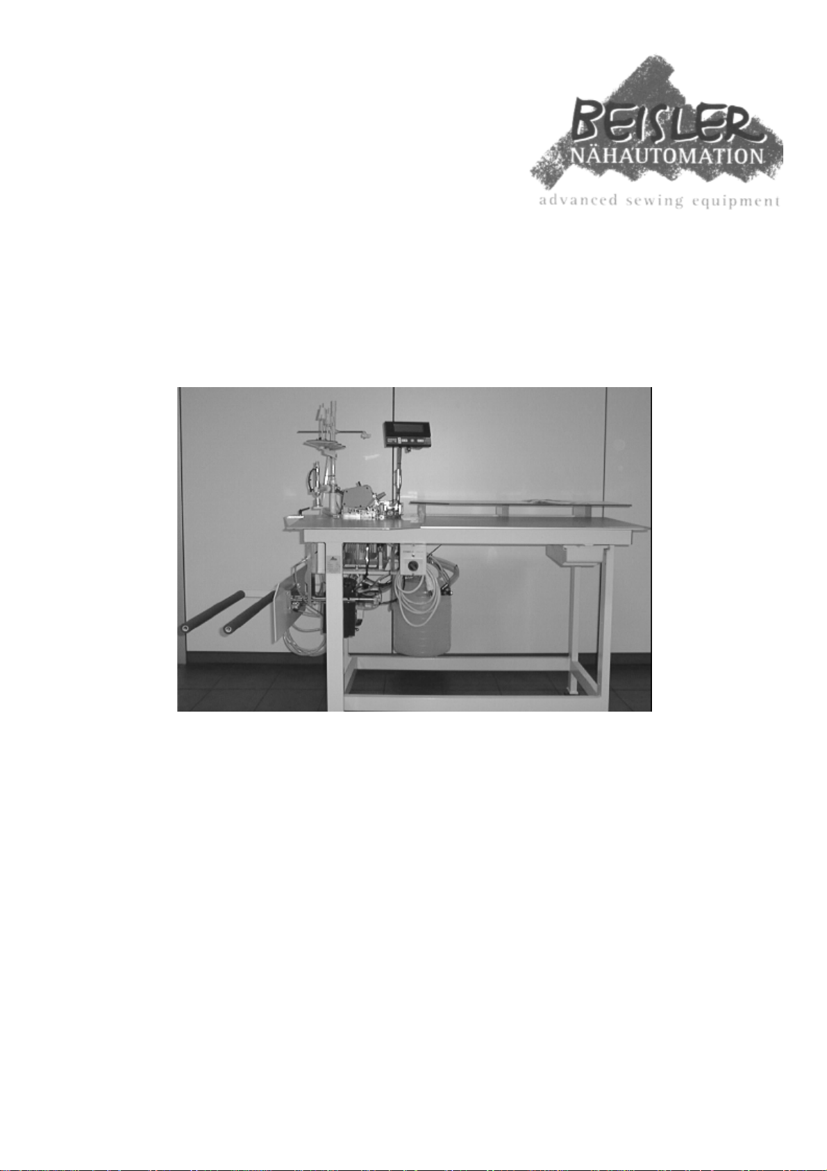
Automatic Single Head
Serging Unit, series 1220/4
Operating instructions
Version 3.0, dated 06-28-1999 – GB
© 1997-99 Beisler GmbH, Hösbach
Frohnradstr. 10 y D-63768 Hösbach y Phone-No. Service: +49-6021-501940 y Fax: +49-6021-540061
Page 2

Betriebanleitung Kurznaht-Automat 2111
© Beisler GmbH, Hösbach
Page 3

Contents
1 Security advice and warning hints 1-1
1.1 Classification 1-1
1.2 Range of validity 1-2
1.3 Authorized person 1-2
1.4 General security advice and warning hints 1-3
1.5 Copyright 1-4
2 Preliminary remarks 2-1
2.1 Introduction 2-1
2.2 Limitation of liability 2-2
2.3 Guarantee regulations 2-3
2.4 Use as agreed 2-4
2.5 Description of the machine 2-4
2.6 Major parts of the machine 2-5
3 Security 3-1
3.1 Available security systems 3-1
3.1.1 Main switch 3-2
3.1.2 Overload protection switch 3-2
3.2 Security measures of the operator 3-3
4 Delivery, transportation, storage 4-1
4.1 Delivery 4-1
4.2 Transportation 4-1
4.3 Storage 4-2
5 Installation 5-1
5.1 Technical data 5-1
5.2 Mechanical installation 5-2
5.2.1 Unpack and put up 5-2
5.2.2 Connection of air supply 5-2
5.2.3 Electrical installation 5-3
5.3 First putting into operation 5-4
6 Operation of the machine 6-1
6.1 Controls and indicators 6-1
6.1.1 Operating device 6-2
6.1.2 Reset key 6-3
6.1.3 Main switch 6-3
6.2 Operation 6-3
6.2.1 Machine sequence 6-3
6.2.2 Program operation 6-4
6.2.3 Select a program 6-5
Page 0-1
Page 4

Operating manual Automatic single head serging unit 1220/4
6.3 Create own programs 6-5
6.3.1 Enter machine code 6-6
6.3.2 Set language 6-6
6.3.3 Adjust setup data 6-6
6.3.4 Use of the storage module 6-13
6.4 Height adjustment of the contour guiding 6-17
6.5 Short operating instructions for the
sewing head 6-18
6.5.1 Adjust height of needle pole 6-18
6.5.2 Distance of the left grab to the needle 6-20
6.5.3 Distance of the right grab to the needle 6-22
6.5.4 Rear needle protection 6-24
6.5.5 Front needle protection 6-26
6.5.6 Position of the transporter 6-28
6.5.7 Transporter height 6-29
6.5.8 Stroke of the presser foot 6-30
6.5.9 Presser foot 6-32
6.5.10 Upper knife 6-34
6.5.11 Bottom knife 6-35
6.5.12 Thread regulation for ‘Überwendlich’ grab 6-36
6.5.13 Oil filter changing 6-37
6.5.14 Oil changing 6-38
7 Cleaning and maintenance 7-1
7.1 Maintenance of the machine 7-1
7.1.1 Water separator at air connector 7-2
7.1.2 Oil level in the sewing head 7-2
7.1.3 Check the drive belt 7-3
7.2 Required cleanings 7-3
Page 0-2 © Beisler GmbH, Hösbach
Page 5
Chapter 1: Security advice and warning hints
1 Security advice and warning
hints
1.1 Classification
Three different types of hints are used in this manual, which are
indicated with different symbols and signalling words:
DANGER
This indicates a possibly dangerous situation or action, which may
cause injuries to persons or severe damage to the machine.
ATTENTION
This indicates a situation or action, which may cause damage to the
machine.
Hint
This indicates hints for a better use and other helpful information or
hints.
Please obey all rules and regulations.
Page 1-1
Page 6

Operating manual Automatic single head serging unit 1220/4
1.2 Range of validity
This operating manual is valid for Automatic single head serging units
manuactured by the Beisler GmbH named „Automatic single head
serging unit 1220/4“.
This operating manual is not valid for the sewing head applied in the
machine. Please refer to the operating manual of the sewing head
delivered with the machine, for which we don’t take any liability.
Further security advice (verbal and written) for this machine or the
components will not be repealed by this manual.
1.3 Authorized person
DANGER
Danger might arise for persons, things and environment by
inappropriate operation of this machine. Installation and maintenance
duties may only be carried out by authorized staff.
Persons are regarded as authorized, who are able to recognize possible
danger and judge the assigned duties from their technical education
and experience.
Page 1-2 © Beisler GmbH, Hösbach
Page 7
Chapter 1: Security advice and warning hints
1.4 General security advice and warning hints
DANGER
Danger might arise for persons, things and environment by
inappropriate operation of this machine. Installation and maintenance
duties may only be carried out by authorized staff.
GEFAHR
Danger of injuries in the range of the sewing head! Don’t grasp into
the affected area of the needle during the sewing process.
DANGER
Before any operations at or with the machine (putting into operation,
operation, maintenance, repair, etc.) the person carrying out has to
read and understand this manual with each appendix completely.
DANGER
Before carrying out maintenance or repair duties, the mains supply
must be cut off. Additionally pressure must be released from the pneumatical system.
ATTENTION
The machine will be destroyed by a connection to a wrong mains
voltage! See the section ‘Technical data’ before connecting the power
supply.
Page 1-3
Page 8

1.5 Copyright
© 1997-99 Beisler GmbH, Hösbach
Automatic single head serging unit
The Automatic single head serging unit 1220/4 and this operating
manual with all parts are protected on copyright. Manufacture without
license will be prosecuted by law. All rights reserved on this operating
manual, including reproduction in any thinkable way, either by
copying, printing, on any data recording media or in translated form.
Reproduction of this operating manual - even in extracts - only with
written approval by Beisler GmbH.
This operating manual contains a description of the product, but no
promise of certain qualities or results of use. The operating manual has
been proved before delivery. The Beisler GmbH takes the liability,
that this operating manual if free of errors reducing its value for the
estimated use. The editors don’t take liability for consecuting damage
arising through application of the operating manual. We are always
thankful for hints and ideas.
Operating manual Automatic single head serging unit 1220/4
The technical standard of the common delivery of product and
operating manual by the Beisler GmbH is decisive, if not other
information is given. Technical changes without prior notice are
reserved, previous operating manuals loose validity.
The general conditions of sales and delivery of the Beisler GmbH are
valid.
Do you have questions or problems with installation or putting into
operation? Don’t hesitate to call us:
Beisler GmbH
Frohnradstr. 10
D-63768 Hösbach
Tel: (+49) 6021 / 50 19 0
Fax: (+49) 6021 / 50 19 10
Page 1-4 © Beisler GmbH, Hösbach
Page 9
Chapter 2: Preliminary remarks
2 Preliminary remarks
2.1 Introduction
This operating manual adresses to the operator of the machine, that is
the person that works with the machine. It is not a technical manual.
Please ask questions exceeding the contents of this operating manual
to our service staff.
ATTENTION
All service and maintenance duties at this machine may only be carried
out by qualified staff (qualified electrical employee or electrotechnical instructed person according to IEC 364 and DIN EN 60204-
1). Machine operation may only be carried out by an instructed person,
who had read and understood this operating manual completely.
ATTENTION
Any structural changes to the machine, either electrically,
mechanically or regarding the machine control, are suspect to the
responsibility of the machine owner.
The following documents are part of the documentation of the
Automatic single head serging unit 1220/4:
1. Electrical wiring pans
2. Parts list
3. Operating manual of the sewing head
Please check the documents delivered with the machine for
completeness.
Page 2-1
Page 10

Operating manual Automatic single head serging unit 1220/4
2.2 Limitation of liability
We guarantee the faultless functioning of our product in accordance
with our advertising, the product informations edited by the Beisler
GmbH and this manual. Further product-features are not guaranteed.
We take no liability for the economy and faultless function if the
product is used for a different purpose then that described in the
chapter "Use as agreed".
Compensation claims are generally impossible, except if intention or
cul-pable negligence by the Beisler GmbH is proved, or if assured
product-features are not provided. If this machine is used in
environments, for which it is not suited or which do not represent the
technical standard, we are not responsible for the consequences.
We don't accept responsibility for damages at installations and systems
in the surroundings of this machine, which are caused by a fault of the
product or an error in this manual.
We are not responsible for the violation of patents and/or other rights
of third persons outside the Federal Republic of Germany.
We are not liable for damages, which result from improper operations
according to this manual. We are not liable for missed profit and for
consecuting damages due to non-regardance of security advices and
warning hints. We don't accept liability for damages which resulted
from the use of tools and accessoires which are not delivered and/or
approved by the Beisler GmbH.
The products of the Beisler GmbH are designed for a long life. They
represent the standard of technique and science and were checked on
all functions individually before delivery. The electrical construction
corresponds to the current norms and regulations, particularly DIN
5713 / VDE 0113. Beisler GmbH is doing product and market
research for the further development and permanent improvement of
their products. In the case of faults and/or technical trouble please
contact the Beisler GmbH service staff. We assure that suitable
measures will be done immediately.
The Beisler GmbH guarantee regualtions are valid, which we will send
to you on demand.
Page 2-2 © Beisler GmbH, Hösbach
Page 11

Chapter 2: Preliminary remarks
2.3 Guarantee regulations
We guarantee the fault-free functioning of the Automatic Single Head
Serging Unit, Series 1220/4 according to this operating manual except
the tools for a time range of six months after delivery. If the machine is
used in double- or triple-shift operation, the term of guarantee is
reduced to three or two months.
The term of guarantee starts with the date of delivery to the customer,
independant from the time of putting into operation. Guarantee will be
spoiled, if the machine isn’t installed and operated according to this
operating manual and the regulations given by the Beisler GmbH staff.
A cost-free repair is only possible, if all regulations considering
storage, transportation and putting into operations have been obeyed.
Customers and third persons may only mesh with the machine after
getting a written approval by the Beisler GmbH. The Beisler GmbH
takes no responsibility for injuries and damages arising from nonobeyance of this stipulation. All warranty will be spoiled in this case.
The Beisler GmbH takes no responsibility for faults of the machine as
consequence of defective or functional faulty equipment in the
surrounding of the machine or by the use of accessoires, which were
not delivered by the Beisler GmbH.
The general conditions of sale and delivery of the Beisler GmbH are
valid.
Page 2-3
Page 12

2.4 Use as agreed
The Automatic Single Head Serging Unit, Series 1220/4 has been
developed for the serging of trouser parts. The machine overcasts side
and crotch sews at front and back trousers and stacks the manufactured
parts automatically.
DANGER
This machine has been developed and build for a certain purpose.
Adaptions may influence security equipments negatively. We
recommend to contact our service staff in such a case.
Operating manual Automatic single head serging unit 1220/4
2.5 Description of the machine
The Automatic Single Head Serging Unit, Series 1220/4 allows the
serging of trouser parts. Side and crotch sews can be overcasted
automatically, while the overlapping is nearly complete.
All components of the machine are mounted on a base frame made of
square steel pipes and controlled by an innovative micro-processor
system.
Machine operation is achieved with an operation device. Here you can
open several control programs, define new programs and check all
machine components individually for maintenance and repair duties.
Page 2-4 © Beisler GmbH, Hösbach
Page 13
Chapter 2: Preliminary remarks
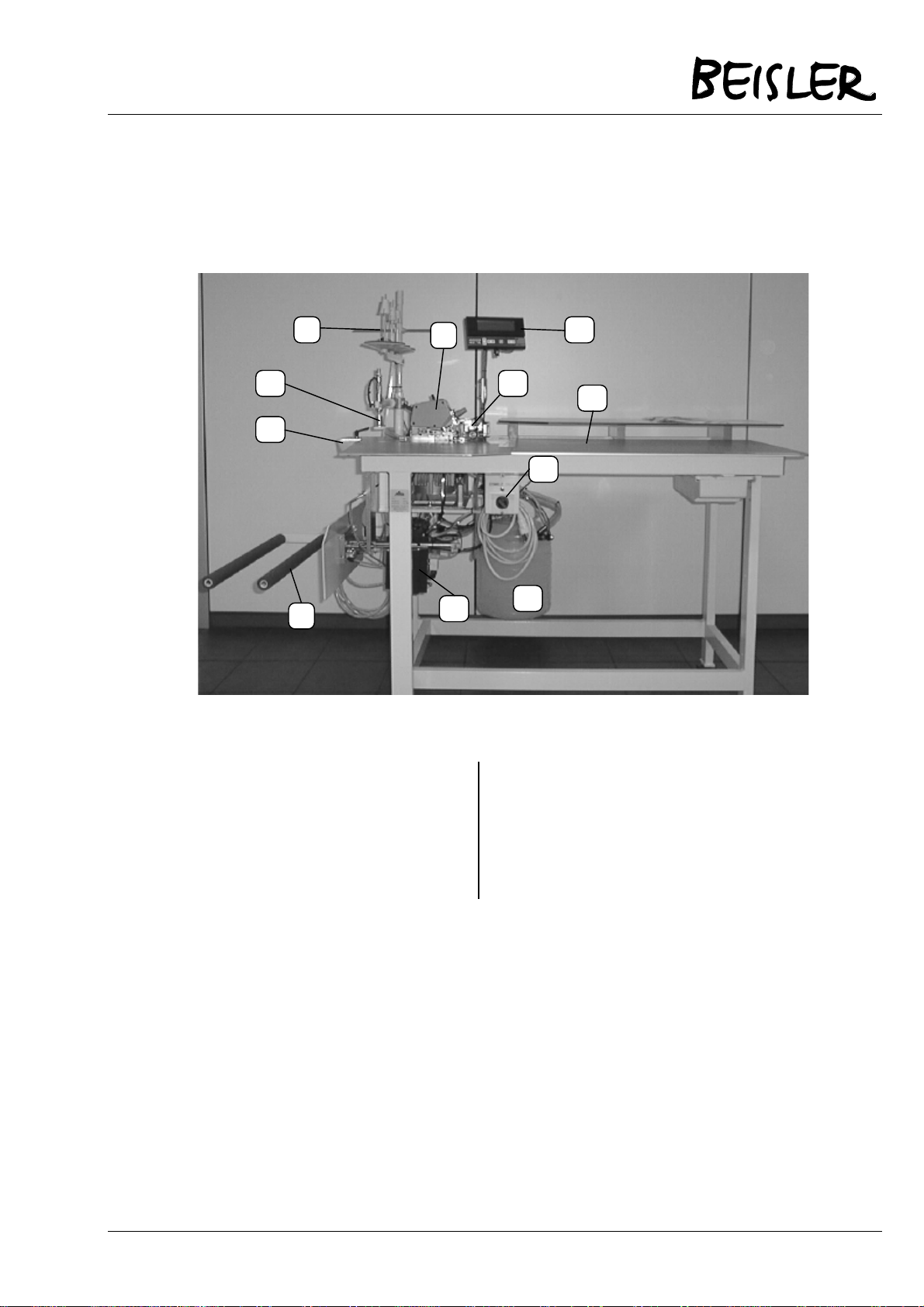
2.6 Major parts of the machine
L
K B
J
H
Pict. 1 Major parts of the machine
A Sewing head G Motor
A
G
F
C
D
E
B Contour guide H Stacker clamp
C Operation device J Blade with clamp lever
D Working table K Stamp
E Main switch L Spool rack
F Waste container
Further information on the components are contained in the coming
chapters.
Page 2-5
Page 14

Operating manual Automatic single head serging unit 1220/4
Page 2-6 © Beisler GmbH, Hösbach
Page 15

Chapter 3: Security
3 Security
The topic of this chapter is the security exclusively. Please see chapter
1 for the general security advice and warning hints and the security
and warning hints in the other chapters of this operating manual.
3.1 Available security systems
DANGER
Check all security systems daily for functioning and effectivity. The
machine may not be put into operation if the security systems and
installations hasn’t been checked previously.
DANGER
Changes to the machine may influence function and effectivity of the
security systems negatively.
Page 3-1
Page 16
Operating manual Automatic single head serging unit 1220/4
C
A
B
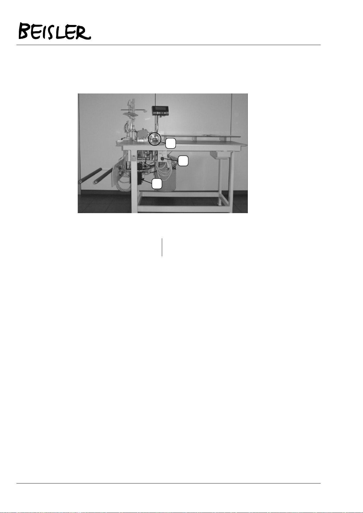
Pict. 2 Available security systems
A Main switch B Motor overload protection
3.1.1 Main switch
The main switch is located at the front side of the machine below the
working table. It is used to cut off the machine’s power supply.
3.1.2 Overload protection switch
If the motor is overloaded, the automatic protection switch reacts and
stops the sewing process. Check and repair the reason for the
overloading and put the machine into the starting position then.
switch
Page 3-2 © Beisler GmbH, Hösbach
Page 17

Chapter 3: Security
3.2 Security measures of the operator
The security systems of this machine work passively, that means that
they can only react on certain incidents. To achieve the required
security for your health and that of your collegues, active measures of
the operator are required.
Please obey the following general rules for the use of this machine:
1. Always work concetrated and avoid actions with a risk.
2. Don’t try to bridge existing security systems or to disable
them in any way.
3. Check all security systems on function and effectivity
before starting work.
4. Cut off the power supply before opening the power supply
unit.
5. Switch off the machine with the mains / emergency stop
switch, before executing cleaning and mainetenance duties.
Page 3-3
Page 18

Operating manual Automatic single head serging unit 1220/4
Page 3-4 © Beisler GmbH, Hösbach
Page 19
Chapter 4: Delivery, transportation, storage
4 Delivery, transportation, storage
4.1 Delivery
Hint
Check right after receiving the machine, whether all parts according to
the parts list are complete and without damage. Later claims can’t be
accepted.
If you see damage to the transportation packing of the machine, which
indicates a possible damage to the delivered parts, don’t hesitate to
claim this to the transportation company.
4.2 Transportation
Generally it is possible to move the machine. Obey the following
hints:
1. Cut off the power supply, release the pneumatical pressure.
2. Fix movable and loose parts.
3. Lift the base with a hoisting device and be sure to lift
possible additional devices (e.g. stacker). If the machine is
equipped with transportation casters (option), you will have
to release the brakes at every caster.
4. Move the machine carefully to the new location.
ATTENTION
Attention when moving the machine on sloping areas! Enormous pull
power arises from the machine weight.
Page 4-1
Page 20

4.3 Storage
If no other agreement is fixed, the following limitations have to be
kept:
1. In closed rooms only.
2. Temperature range -10 ... +45 °C.
3. Humidity max. 80% non-condensing.
ATTENTION
If stored or transported in improper environments, the machine can be
damaged severely. Damages may not be visible from the outside.
Operating manual Automatic single head serging unit 1220/4
Page 4-2 © Beisler GmbH, Hösbach
Page 21
Chapter 5: Installation
5 Installation
ATTENTION
Installation and putting into operation may only be carried out by
mechanically and electrically qualified staff. These people must read
and understand the complete operating manual before starting.
5.1 Technical data
Dimensions
Table height
Weight
Mains power
Power consumption
req. air pressure
req. air quality
Air consumption
1750 x 860 x 1700 mm (L x W x B)
940 mm, adjustable
120 kg
220 V AC
0,7 kW
6 bar
oil-free
20 NL/WD
Page 5-1
Page 22

Operating manual Automatic single head serging unit 1220/4
5.2 Mechanical installation
ATTENTION
Check before starting the installation, whether the desired location
meets the requirements (see chapter 5.1, technical data). This is very
important regarding the stability of the ground.
5.2.1 Unpack and put up
1. Remove the packing material and possible transportation
protections.
2. Position the machine on a solid and horizontal ground.
3. Level the machine to a horizontal stand using the adjustable
frame feet.
5.2.2 Connection of air supply
B
A
Pict.. 3 Connection of air supply (machine backside)
C
Page 5-2 © Beisler GmbH, Hösbach
Page 23

Chapter 5: Installation
1. Connect the air pipe (A) to your air system.
2. Open the air supply of your air system.
3. Level the air pressure to 6 bar using the control (B); the air
pressure can be read at the scale (C).
ATTENTION
We recommend to switch off the air supply when the machine is not in
duty. Use the black control (B in Pict. 3).
5.2.3 Electrical installation
Hint
All work at the electrical components of the machine may only be
carried by qualified staff (qualified electrical employee or instructed
person according to IEC 364 and DIN EN 60204-1).
DANGER
Parts under electrical current! Without cutting off the power supply,
you might be injured severely. Please obey the security advice given in
chapter 1.
ATTENTION
The machine will be destroyed by connecting to a wrong mains
voltage! Check, whether the requirements from chapter ‘Technical
data‘ meet the local conditions.
1. Use the power cord located at the backside of the machine.
2. Plug it into a socket.
3. Lay the cord in a way, that the danger of stumbling is
avoided.
Page 5-3
Page 24

Operating manual Automatic single head serging unit 1220/4
DANGER
Danger to life from unsufficient grounding! Do a grounding according
to DIN EN 60204-1.
5.3 First putting into operation
This machine has been configured to the individual requirements of
the customer. The first putting into operation can be done easily:
1. Adjust the machine to a horizontal stand.
2. Connect power and air supply.
3. Switch on the machine using the mains / emergency stop
switch at the front side of the machine.
4. Check all security systems for function and efficiency.
DANGER
The machine may only be used for production purposes, after the
security systems have been checked. If a security doesn’t work
adequately, it must be repaired first.
As a factory setting, several production programs are contained in the
buffer of the machine. You may use one of them or create your own
programs.
Page 5-4 © Beisler GmbH, Hösbach
Page 25

Chapter 6: Operation
6 Operation of the machine
DANGER
This machine may only be operated by qualified staff, who had read
and understood this operating manual completely.
6.1 Controls and indicators
A
B
C
Pict. 4 Controls and indicators
A Operating device C Main switch
B Reset key
Page 6-1
Page 26

6.1.1 Operating device
During production the machine can be operated with the operating
device; existing programs can be called and new programmed. You
will find the program stop button at the device.
Operating manual Automatic single head serging unit 1220/4
A
B C D
Pict. 5 Operating device
Display
A
Cursor keys
B
Special key
C
Minus / plus keys
D
The elements of the operating devices have the following occupations:
Display: all information required for the operation of the
machine are indicated here.
Cursor keys: use them to move the cursor and mark all
required commands and options.
Special key: press this key if additional information are
required for a setting.
Minus / plus key: are used to switch on/off functions, to increa-
se/reduce numerical values and to select programs.
Page 6-2 © Beisler GmbH, Hösbach
Page 27

Chapter 6: Operation
6.1.2 Reset key
The reset key can be used to reset a program, if an error occured
during insertion for a pre-seam. Insert the trouser part again and
execute the pre-seam.
The reset key is only enabled if it is pressed before the main seam.
6.1.3 Main switch
Use the main switch to enable/disable the power supply of the
machine.
6.2 Operation
6.2.1 Machine sequence
A
Pict. 6 Sewing area
B
C
Page 6-3
Page 28

Operating manual Automatic single head serging unit 1220/4
The production cycle of the machine is divided into several sections:
1. The operator inserts a trouser part from the right side (see
white arrow in Pict. 6) under contour guiding (C) and photo
cell (B).
2. After photo cell (B) switched dark, the sewing process starts
(needle Pos. (A) in Pict. 6); the contour guiding will be
lowered.
3. The trouser part will be sewed.
4. After the photo cell (B) switches light, the seam will be
ended and the stamp comes down.
5. The contour guiding drives up.
6. The stacker clamp advances to the front.
7. The stamp drives up.
8. The trouser part is stacked with an air-blow.
6.2.2 Program operation
The machine is operated with programs, which are stored in the
memory and can be opened by the operator. He can choose from
several possibilities:
he can select an existing program
he can change an existing program
he can create and adjust a new program
All possibilities will be explained in the following.
Page 6-4 © Beisler GmbH, Hösbach
Page 29

Chapter 6: Operation
6.2.3 Select a program
In the daily production process, the machine operator will only have to
select an existing program. The following programs exist as a factory
setting:
Program 1: 1 main seam
Program 2: 1 pre-seam with consecutive main seam
Program 3: 2 pre-seams with consecutive main seam
Program 4: 2 pre-seams, 1 seat seam with consecutive main
seam
Program 5: 1 seat seam, 2 pre-seams with consecutive main
seam
Program 6: 1 main seam without stop after photo cell lighted
The currently selected program is displayed in the left upper corner of
the display (program 1 is selected in Pict. 5).
To select a different program, you have to move the cursor on the
program number and press the ‘+’ / ‘-‘ keys repeatedly, until the
desired program number is displayed.
6.3 Create own programs
ATTENTION
The changing and creation of programs should be done by
experienced personell. The functionality of the machine can be
influenced badly by wrong programming.
Hint
All functions and options are displayed as icons in a rectangle in the
programs. Generally, a rectangle striked out twice means: function
disabled. If the rectangle isn’t striked out, the function is enabled.
To create an own program, you will first have to adjust the setup data
and then create the program. Setup data can only be displayed, if the
machine code has been entered before:
Page 6-5
Page 30

6.3.1 Enter machine code
ATTENTION
The machine code protects from unauthorized access to the setup
data. Wrong setup data affect the functionality of the machine
negatively. The machine code should not be accessible to unauthorized persons.
1. Move the cursor to the program number using the keys
.
Operating manual Automatic single head serging unit 1220/4
2. Press the key
3. Press the key
the key symbol.
4. Press
5. Press
disappears.
6.3.2 Set language
If you want to work with a different operation language, you can select
this on page „Setup -00“:
1. After entering the machine code, press
desired operation language using
2. Press
6.3.3 Adjust setup data
The setup data of this machine are contained on the pages ‘-01’, ‘-02’,
‘-03’ and ‘-10’:
repeatedly, until „Setup -00“ is displayed.
to place the cursor on the first ‚x‘ below
three times to change all ‘x’ to ‘0’.
to confirm the entered code. The key symbol
and select the
.
to place the cursor on „Setup -00“ again.
Page -01: machine type
Page -02: motor functions
Page -03: machine functions
Page -10: in- and outputs (switch on/off, program)
Use the
Page 6-6 © Beisler GmbH, Hösbach
key to select the page where you want to do changes.
Page 31

Chapter 6: Operation
6.3.3.1 Page -01: machine type
Press the
key after entering the machine code, until the setup page
-01 is displayed:
The machine type is a factory setting and may not be
changed. The selected type is marked with an arrow in
the list of available machine types.
6.3.3.2 Page -02: motor functions
After entering the machine code, press the
page -02 is displayed:
Motor functions like position actor, motor parameters
(turn direction, revs, a.s.o.) and pedal funtions.
The motor functions that can be changed on this setup page, are
gathered in three groups:
Turn direction, position actor
Place the cursor on this symbol and press the
special key. Now adjust the turn direction and
the needle-zero and -top position.
Motor parameters:
Here you can adjust revs and belt disc diameter.
key twice, until setup
Pedal functions:
Here you can assign several functions to the
pedal (not required here and therefor
deactivated).
Press the key until the desired symbol is marked and then the
key to open the adjustments.
Page 6-7
Page 32

Adjust turn direction
Operating manual Automatic single head serging unit 1220/4
Mark the symbol ‘Position actor’
Press the
SETUP-02
After opening the page, the cursor is placed on the icon of
the turn direction. Press the
turn direction (viewed on the belt disc).
Adjust needle zero and top position:
Use the arrow keys to move the cursor towards the right on
the zero position of the needle.
Turn the hand wheel of the sewing head some turns with
impetus, until the below the icon of the turn direction
changes.
Continue turning the hand wheel, until the needle top stands
at the upper edge of the stitch plate.
Press the
displayed in the needle position rectangle.
Use the arrow keys to move the cursor up on the symbol „II
Pos.“ and turn the hand wheel in turn direction, until the
needle stands in the desired top position.
Read the value displayed below the turn direction icon and
use the
Pos.“.
Move the cursor downwards on „I Pos.“ and enter the value
‚115‘ here.
Press the
key to enter this value into the rectangle of „II
.
key; the following will be displayed:
--290
0
115
key to accept the position. A ‚0‘ will be
key to close the page.
III POS.
II POS.
0
I POS.
key to select the desired
Page 6-8 © Beisler GmbH, Hösbach
Page 33

Chapter 6: Operation
Set motor parameters:
SETUP-02
RESET
MIN.:
MAX.:
Mark the symbol „Motor parameters“
Press the
key until the following will be displayed:
.
MIN.: 400
MAX.: 8000
[ 4500]
RESET
ON
5400
Pull: 75
100%
ACC.
67
Use the keys to mark the different values in
the window.
Use the
must be set to ‘ON’.
minimum revs of the sewing head; 400 is the optimized
value.
maximum revs of the sewing head:
Pegasus S52: 8000
keys to adjust the desired values:
80%
DEC.
PUL.:
ACC.:
DEC.:
KP:
mounted belt drive disc size; must be set to ‘75’
acceleration curve; must be set to ‘100%’
decrease parameter: must be set to 80%
add. motor break; must be set to 16
Press the key to close the page.
Page 6-9
Page 34

Operating manual Automatic single head serging unit 1220/4
6.3.3.3 Page -03: Machine functions
After entering the machine code, press
page -03 is displayed:
SETUP
-03
A
three times, until setup
S
Here you can edit several functions of the machine. Only four of them
are relevant for this machine:
Presser foot lifting:
Here, several time and voltage values for the
lifting, holding and lowering of the presser foot
can be adjusted.
Light barrier (Photo cell mode):
Here you can adjust several options for the
light barrier.
To adjust one of the machine functions, select the desired symbol
using the
‘Presser foot lifting’ is selected. Now press the
settings of the selected machine function.
Adjust presser foot lifting:
After selecting the symbol of the presser foot lifting and opening the
adjustment page, the following will be displayed:
keys. In the drawing shown above, the symbol
key to open the
Page 6-10 © Beisler GmbH, Hösbach
Page 35

Chapter 6: Operation
SETUP-02
30V
(max)
15 V
[ms]
150
00
120
Move the cursor on the time of maximum power (left value
in the lower line) and use the Plus-/Minus-keys to set the
value ‚150‘. This time is sufficient for the presser foot to be
lifted safely at seam end.
Move the cursor on the value with the holding voltage
(middle of the upper line) and set the value ‚15V‘. This
assures that the magnet valve of the foot lifting will not be
overloaded.
Move the cursor on the value of the start delay (lower line,
right value) and set ‚120‘ ms here. This time is needed that
the pressure foot rests safely on the fabrics after switching
the photo cell dark before sewing starts.
Move the cursor on the two presser foot icons on the right
of the display and use the Plus-key to set both on ‚presser
foot up‘ like shown in the drawing.
Press the
key to close the page.
Set light barrier (photo cell mode):
Use the arrow keys to select the symbol of the light barrier
then use the
press the
key to switch the photo cell to „switching dark“. Now
key.
and
After executing all settings on setup page –02, move the cursor on the
page number –02 and press the Minus-key to select setup page –10,
where you can activate and set inputs and outputs.
Page 6-11
Page 36

Operating manual Automatic single head serging unit 1220/4
6.3.3.4 Page -10: Inputs and outputs
Inputs a switches and keys and are named ‘M1’ ... ‘M6’. Outputs are
all available magnet valves and are named ‘F1’ ... ‘F7’.
The programmin of an input/output is done in three steps:
1. Switch on or off.
2. Set start mode.
3. Set time values.
The inputs and outputs are occupied as follows:
I/O Valve description Connector
Y0 Lift sewing foot A-1
F1 Y2 Table blowing A-3
F2 Y3 Contour guiding A-5
F3 Y13 Sucking nozzle A-5
F4 Y4 Contour roll A-7
F5 Y5 Kett-up A-9
F6 Y6 Holding stamp A-11
F7 Y7 Stacker impulse A-13
M1 Reset key below the operation device Pin 2-4
After you have selected setup page -10, the following will be
displayed:
SETUP
F5
F6
-10
F1
M1
F2
F3
M3M2
F4
M4
M5
F7
M6
Page 6-12 © Beisler GmbH, Hösbach
Page 37

Chapter 6: Operation
Use the keys to select the desired input/output and
switch them on/off using the
input/output switched off is crossed with two lines (M2-M6 in the
drawing).
6.3.4 Use of the storage module
A storage module KK195 is delivered together with the machine, on
which the factory-set programs and parameters are contained. After
replacing the machine control or a total loss of data, they can be read
into the machine.
You can save you individual sewing programs on an additional storage
module, to protect them from being lost. Storage module are available
from Beisler.
keys. The symbol of and
6.3.4.1 Re-load standard programs
The standard programs can be reloaded easily:
1. Switch off the machine using the mains switch.
2. Plug the storage module into the corresponding slot in the
operating device. This can be found at the right side of the
device.
3. Switch on the machine and use the
mark the entry ‘Setup / All programs’.
4. Press the
key.
5. The data will be read into the machine control.
6. Pull out the storage module. Now you will have to set the
needle position again (see section 6.3.3.2).
7. Then the machine is ready for sewing, sewing program 001
will be displayed.
keys to
Page 6-13
Page 38

Operating manual Automatic single head serging unit 1220/4
6.3.4.2 Save setup data on the storage module
1. Select the page ‚Setup –00‘.
2. Enter the access code (see section 6.3.1).
3. Move the cursor completely to the right onto the letter ‚W‘
(= write).
4. Plug the storage module KK195 into the slot on the right
side of the operating device.
5. Press the Plus-key to copy the setup data from the control
on the storage module.
6. Press the Special-key to terminate the procedure.
6.3.4.3 Read setup data into the machine control
1. Select the page ‚Setup –00‘.
2. Enter the access code (see section 6.3.1).
3. Move the cursor completely to the right onto the letter ‚R‘
(= read).
4. Plug the storage module KK195 into the slot on the right
side of the operating module.
5. Press the Plus-key to read the setup data from the storage
module into the machine control.
6. Press the Special-key to terminate the procedure.
6.3.4.4 Copy all sewing programs on the storage module
1. Select the page ‚Index 000‘.
2. Enter the access code (see section 6.3.1).
3. Press the Special-key.
4. Plug a storage module into the slot on the right side of the
operating device.
5. Move the cursor on the letter ‚W‘ (= write).
6. Press the Plus-key to copy all sewing on the storage
module.
7. Press the Special-key to terminate the procedure.
Page 6-14 © Beisler GmbH, Hösbach
Page 39

Chapter 6: Operation
6.3.4.5 Read all sewing programs into the machine control
ATTENTION
Before you read all sewing programs into the machine control, you
will first have to delete all sewing programs in the control. This
cannot be undone.
1. Select the page ‚Index 000‘.
2. Enter the access code (see section 6.3.1).
3. Press the Special-key.
4. Plug the storage module into the slot on the right side of the
operating device.
5. Move the cursor on the letters ‚PRG‘.
6. Press the Plus-key twice to delete all sewing programs from
the machine control.
7. Move the cursor on the letter ‚R‘ (= read).
8. Press the Plus-key to copy all sewing programs from the
storage module into the machine control.
9. Press the Special-key to terminate the process.
6.3.4.6 Copy single sewing programs on the storage module
Hint
To save single sewing programs, a separate storage module is
required for each sewing program to be saved.
1. Select the program, which you want to copy on the storage
module.
2. Press the Special-key.
3. Move the cursor on the letter ‚W‘ (= write).
4. Plug an empty storage module into the slot on the right side
of the operating device.
5. Press the Plus-key to write the program data to the storage
module.
6. Press the Special-key to terminate the process.
Page 6-15
Page 40

Operating manual Automatic single head serging unit 1220/4
6.3.4.7 Copy single sewing programs into the machine control
Hint
Before program data can be copied into the control, the data of the
desired program location must be deleted before. This cannot be
undone.
1. Select the program page, where you want to copy the
program data to.
2. Press the Special-key.
3. Move the cursor on the letters ‚PRG‘.
4. Press the Plus-key twice to delete possible program data
stored on the selected memory location.
5. Move the cursor on the letter ‚R‘ (= read).
6. Plug the storage module into the slot on the right side of the
operating device.
7. Press the Plus-key to write the program data into the
machine control.
8. Press the Special-key to terminate the process.
Page 6-16 © Beisler GmbH, Hösbach
Page 41

Chapter 6: Operation
6.4 Height adjustment of the contour guiding
The contour guiding achieves an evenly positioning of the trouser part
below the sewing head. Dependant on the thickness of the
manufactured cloth, the height of the contour guiding can be adjusted:
A
Pict. 11 Contour guiding height adjustment
1. Pull the adjusting wheel (A) a little backwards.
2. Set it to one of the four engage,emt position (1 = smallest
height, 4 = biggest height).
Page 6-17
Page 42

Operating manual Automatic single head serging unit 1220/4
6.5 Short operating instructions for the
sewing head
ATTENTION
The short operating instructions provided here are an excert of the
complete operating manual of the sewing head. This operating
manual must be read completely and all instructions must be obeyed.
The Beisler GmbH takes no responsibility for the correctness of the
following.
6.5.1 Adjust height of needle pole
The distance between needle top and stitch plate should be 9,7 to 9,9
mm in the upper endpoint.
Pict. 12 Adjust height of needle pole (1)
Page 6-18 © Beisler GmbH, Hösbach
Page 43

Chapter 6: Operation
Pict. 13 Adjust height of needle pole (2)
Pict. 14 Adjust height of needle pole(3)
1. Turn off the cover screws (1) and remove the cover (2).
2. Move the needle pole to the upper position by moving the
hand wheel.
3. Swing out the sewing foot and insert a new needle.
Page 6-19
Page 44

Operating manual Automatic single head serging unit 1220/4
4. Loosen screw (3) until the needle pole can be pushed hardly
only.
5. Push the needle pole that the distance between needle top
and stitch plate is 9.7 to 9.9 mm.
6. Tighten screw (3) in this position.
7. Fix the cover (2) again.
6.5.2 Distance of the left grab to the needle
Pict. 15 Distance of the left grab (1)
Pict. 16 Distance of the left grab (2)
Page 6-20 © Beisler GmbH, Hösbach
Page 45

Chapter 6: Operation
Pict. 17 Distance of the left grab (3)
6.5.2.1 Crosswise to the sewing direction
The distance between mid of the needle and grab top should be 2.3 to
2.5 mm on the left change point.
1. Remove the stitch plate, front transporter and the front and
rear needle protection.
2. Move the grab into its left change point.
3. Loosen screw (1) and move the grab to the stop (2).
4. Tighten screw (1).
5. Loosen screw (3) a little that the grab carrier (4) can be
turned hardly.
6. Turn the grab carrier that the distance between mid of
needle and grab top is 2.3 to 2.5 mm.
7. Do not tighten screw (3) yet.
6.5.2.2 In seam direction
The distance between grab top and needle should be 0 to 0.05 mm.
1. Turn the hand wheel in turn direction until the grab top
stands exactly in the middle of the needle.
2. Push the grab carrier (4) that the distance between grab
carrier and needle is 0 to 0.05 mm.
3. Check the adjustment crosswise to the seam direction;
possibly do some additional adjustments.
4. Tighten screw (3).
Page 6-21
Page 46

Operating manual Automatic single head serging unit 1220/4
6.5.3 Distance of the right grab to the needle
Pict. 18 Distance of the right grab to the needle (1)
Pict. 19 Distance of the right grab to the needle (2)
Page 6-22 © Beisler GmbH, Hösbach
Page 47

Chapter 6: Operation
Pict. 20 Distance of the right grab to the needle (3)
Pict. 21 Distance of the right grab to the needle (4)
6.5.3.1 Crosswise to the sewing direction
When the right grab stands in its upper change point, the distance
between grab top and middle of the needle should be 4.3 to 4.5 mm.
1. Remove thread guidings (1) (2) and cover (3).
2. Move the grab into its upper change position and loosen
screw (4) that the grab can be pushed hardly.
3. Push the grab that the grab shaft (5) stands levelled with the
side of the grab holder.
4. Loosen screw (6) a little.
5. Turn the lever (9) that there is a distance of 4.3 to 4.5 mm
between grab top and middle of the needle. Check that the
pole (7) moves easily in bearing (8).
6. Tighten screw (6).
7. Don’t tighten screw (4) now.
Page 6-23
Page 48

Operating manual Automatic single head serging unit 1220/4
6.5.3.2 In seam direction (to the left grab)
When the right grab crosses the left, distance ‘A’ shall be 0.5 mm and
distance ‘B’ 0.2 mm.
1. Turn the hand wheel in turn direction until the right grab
crosses the left.
2. Turn and push the right grab, that distance ‘A’ is 0.5 mm
and distance ‘B’ 0.2 mm.
3. Tighten screw (4) in this position.
4. Check all adjustements again and readjust them if required.
5. Mount threat guidings (1) (2) and cover (3).
6. Adjust the threat guidings according to the chapter ‘Threat
regulation of the ‘Überwendlich’ grabber’.
The right ‘Überwendlich’ grab depends on the thickness of the needle.
Use the grab with indication number 28 for needles 60-80 NM and
number 22 for needles 80-100 NM.
6.5.4 Rear needle protection
Pict. 22 Rear needle protection (1)
Page 6-24 © Beisler GmbH, Hösbach
Page 49

Chapter 6: Operation
Pict. 23 Rear needle protection (2)
Pict. 24 Rear needle protection (3)
When the top of the left grab stands in the middle of the needle, the
needle protection ((2) in Pict. 23 and (3) in Pict. 24) should push the
needle in a way, that a distance of 0 to 0.05 mm exists between grab
top and needle.
Page 6-25
Page 50

6.5.4.1 Movable versions
1. Turn the hand wheel in turn direction, until the grab top
stands in needle direction.
2. Loosen screw (1) and push the needle protection (2) in a
way, that there is a distance of 0 to 0.05 mm between grab
top and middle of the needle.
3. Tighten screw (4) in this position.
6.5.4.2 Fixed versions
1. Move the hand wheel in turn direction, until the grab top
stands in the middle of the needle.
2. Loosen screws (4) and push the needle protection (3) in a
way, that a distance of 0 to 0.05 mm exists between grab
top and middle of the needle.
3. Tighten screws (4) in this position.
Operating manual Automatic single head serging unit 1220/4
6.5.5 Front needle protection
Pict. 25 Front needle protection (1)
Page 6-26 © Beisler GmbH, Hösbach
Page 51

Chapter 6: Operation
Pict. 26 Front needle protection (2)
A distance of 0.03 to 0.05 mm should exist between needle protection
and needle in the bottom change point of the needle.
1. Turn the hand wheel in turn direction until the needle stands
in its bottom change point.
2. Loosen screw (1) and push the needle protection that there
is a distance of 0.03 to 0.05 mm between needle protection
and needle.
3. Tighten screw (1) in this position.
Page 6-27
Page 52

Operating manual Automatic single head serging unit 1220/4
6.5.6 Position of the transporter
Pict. 27 Position of the transporter (1)
Pict. 28 Position of the transporter (2)
The transporters should stand horizontally in their highest position.
Page 6-28 © Beisler GmbH, Hösbach
Page 53

Chapter 6: Operation
1. Remove cover (1) and cover plate (2).
2. Turn the hand wheel until the transporters stand in their
highest position.
3. Loosen screw (3).
4. Turn disc (4) that the transporters stand horizontally.
Consider that they may not be moved laterally.
5. Tighten screw (3) in this position.
6. Mount cover (1) and cover plate (2).
6.5.7 Transporter height
Pict. 29 Transporter height
When the transporters stand in their highest position, the cogs of the
main transporter (4) should stand 0.8mm, those of the differential
transporter (5) 0.9 to 1 mm and those of the additional transporters (6)
0.6 to 0.7 mm below the top edge of the stitch plate.
Page 6-29
Page 54

Operating manual Automatic single head serging unit 1220/4
1. Remove the stitch plate and loosen screws (1) (2) (3) a
little.
2. Turn the hand wheel until the transporters stand in their
highest positions.
3. Lay on the stitch plate.
4. Adjust the height of the transporters, that the cogs of the
main transporter stand 0.8mm, those of the differential
transporter (5) 0.9 to 1 mm and those of the additional
transporter (6) 0.6 to 0.7 mm above the top edge of the
stitch plate.
5. Tighten screws (1) (2) (3) in this position.
6. Mount the stitch plate.
6.5.8 Stroke of the presser foot
Pict. 30 Stroke of the presser foot (1)
Page 6-30 © Beisler GmbH, Hösbach
Page 55

Chapter 6: Operation
Pict. 31 Stroke of the presser foot (2)
Pict. 32 Stroke of the presser foot (3)
When the piston pole of the cylinder (7) is driven out, the lever (5)
should attach to screw (2) and the space between sewing foot and
stitch plate should be 5 mm. Additionally, a distance of est. 0.3 mm
should be between stop (11) and screw (10) in this position.
Page 6-31
Page 56

Operating manual Automatic single head serging unit 1220/4
1. Loosen nut (1) and turn screw (2) down completely.
2. Swing in the sewing foot and turn the hand wheel, until the
crogs of the transporter stand below the upper edge of the
stitch plate.
3. Loosen screw (3) and press ring (4) backwards til the stop.
4. Tighten screw (3) in this position. Be sure that ring (4) and
lever (5) show no axial play.
5. Press lever (6) down, until there is a distance of est. 5 mm
between sewing foot and stitch plate.
6. In this position you should bring screw (2) with lever (5) in
contact and fix them with nut (1).
7. If lever (5) gets no contact with screw (2) and piston pole of
cylinder (7) is driven out, loosen nut (8) and move cylinder
(7) correspondantly. Tighten nut (8) again.
8. Loosen screw (9).
9. Turn screw (10) in a way, that a distance of est. 0.3 mm is
between it and stop (11). Be sure that lever (6) is pressed
down to the stop.
10.Tighten screw (9) in this position.
6.5.9 Presser foot
Pict. 33 Presser foot (1)
Page 6-32 © Beisler GmbH, Hösbach
Page 57

Chapter 6: Operation
Pict. 34 Presser foot (2)
When the transporters stand in their lowest position, the presser foot
sole should stand up 0.1 to 0.2 mm in the front. Additionally, the hole
of the presser foot should be aligned with that of the stitch plate.
1. Bring the transporters into their lowest position.
2. Loosen screws (1) and (2).
3. Push the presser foot, that the stitch hole of the presser foot
is aligned with that of the stitch plate.
4. Tighten screws (1) and (2) in this position. Be sure that the
sole of the presser foot stands parallel above the stitch plate.
5. Adjust the presser foot by turning screw (3) in a way, that
the sole stands up 0.1 to 0.2 mm in the front.
Page 6-33
Page 58

6.5.10 Upper knife
Operating manual Automatic single head serging unit 1220/4
Pict. 35 Upper knife
In the lowest position of the knife, the front edge of the blade should
stand 0.5 to 1 mm below the upper edge of the stitch plate.
1. Bring the needle in its change point and swing out the
sewing foot.
2. Turn screw (1) out and take out the knife attachment (2)
completely with the knife.
3. Loosen screw (3) and take out the knife.
4. Insert a keen knife into the attachment (2) and fix screw (3)
a little.
5. Screw in knife attachment (2) with screw (1) a little.
6. Bring the knife in its lowest position.
7. Push the knife in a way, that it has a little contact to the
bottom knife and the front edge of the blade stands 0.5 to 1
mm below the upper edge of the stitch plate.
Page 6-34 © Beisler GmbH, Hösbach
Page 59

Chapter 6: Operation
8. Bring stops (4) and (5) in contact with the knife and tighten
screws (1) and (3).
9. Bring the knife into its highest position and loosen screw
(6).
10. Push the bottom knife attachment (7) to the left and let it
spring at the upper knife.
11.Tighten screw (6).
6.5.11 Bottom knife
Pict. 36 Bottom knife
The blade of the bottom knife should stand levelled with the upper
edge of the stitch plate.
1. Swing out sewing foot and cloth plate.
2. Loosen screw (1).
3. Push bottom knife attachment (2) to the left until the stop
and fix screw (1) a little.
4. Loosen screw (3) and remove the old knife.
Page 6-35
Page 60

Operating manual Automatic single head serging unit 1220/4
5. Insert a keen knife into the guiding (4) in a way, that the
blade stands levelled with the upper edge of the stitch plate.
6. Tighten screw (3) in this position.
7. Bring the upper knife into its highest position.
8. Loosen screw (1) and let the bottom knife attachment (2)
swing at the upper knife.
9. Tighten screw (1).
6.5.12 Thread regulation for ‘Überwendlich’ grab
Pict. 37 Thread regulation for ‘Überwendlich’ grab
The position of the threat guidings and pusher depends on the sewed
material, threat and stitch type. Therefore the following setting data
must be regarded as basic values.
1. Bring the right-handed grab into its upper change point.
2. Loosen screw (1) and push threat puller (2) in a way, that a
distance of est. 32 mm exists between screw-mid and loopmid.
Page 6-36 © Beisler GmbH, Hösbach
Page 61

Chapter 6: Operation
3. Tighten screw (1). Be sure that the threat puller (2) stands
vertically.
4. Loosen screws (3) and (4) a little.
5. Bring threat pullers (5) and (6) into the position shown in
Pict. 37.
6. Tighten screws (3) and (4) in this position.
7. Loosen screw (7) a little and bring the threat guiding (8)
into the position shown in Pict. 37.
8. Tighten screw (7) in this position.
9. Loosen screw (9) a little and push the threat guiding in a
way, that screw (9) stands in the middle of the long hole.
10.Tighten screw (9) in this position.
11.Adjust the threat pullers (5) and (6) in ‘+’ or ‘-‘ direction, if
more or less threat is necessary in the seam.
6.5.13 Oil filter changing
Pict. 38 Oil filter changing
Clean or change the oil filter every two years. Additionally, the oil
filter must be cleaned/changed, if the oil pressure indicator (5) doesn’t
move down while machine is working or the oil is polluted.
Reinigen bzw. wechseln Sie den Ölfilter alle 2 Jahre. Außerdem muß
der Ölfilter gereinigt/ausgetauscht werden, wenn Öldruckanzeiger (5)
sich bei laufender Maschine nicht nach unten bewegt oder das Öl
schmutzig ist.
Page 6-37
Page 62

1. Screw out screws (1) of the cover (2).
2. Turn a screw (1) into the filter and turn it out with it.
3. Clean the filter or change it.
4. Insert the seal (4), place the cover (2) and screw in screws
(1).
6.5.14 Oil changing
Operating manual Automatic single head serging unit 1220/4
Pict. 39 Oil changing (1)
Pict. 40 Oil changing (2)
Page 6-38 © Beisler GmbH, Hösbach
Page 63

Chapter 6: Operation
4 weeks after putting into operation and then every two years, the oil
of the sewing head must be changed.
1. Turn off release screw (1) and catch the oil in a receptacle.
2. Turn in release screw (1) again.
3. Turn off screw (2) and fill in oil, until the top of the oil
level indicator (3) has reached the upper mark in the oil
viewing glass (4).
4. We recommend Pfaff-sewing machine oil or oil with a
viscosity of 15 mm²/s at 50°C and a density of 0.865 g/cm³
at 15°C.
5. Turn in screw (2).
Page 6-39
Page 64

Operating manual Automatic single head serging unit 1220/4
Page 6-40 © Beisler GmbH, Hösbach
Page 65

Chapter 7: Cleaning and maintenance
7 Cleaning and maintenance
7.1 Maintenance of the machine
This machine works nearly free of maintenance. To achieve the
maximum ability of the machine for a long term, some regular
maintenance duties are required.
DANGER
Before starting maintenance and repair duties, the following power
down procedures are to be executed. Otherwise there could be
danger to life.
Cut off mains power
switch the mains / emergency stop switch to ‘0’ and assure
that it can’t be switched on
check whether the machine is without current and that there
is no statical loading
Switch off pneumatic system
close the main gauge
ventilate all pipes and gauges
Page 7-1
Page 66

Operating manual Automatic single head serging unit 1220/4
7.1.1 Water separator at air connector
Check the water separator (A) daily for
contained water. Release the water by
pressing the release button (B).
A
B
Pict. 41 Air maintenance
unit
7.1.2 Oil level in the sewing head
Pict. 42 Check oil level in the sewing head
Check the oil level in the sewing head regularly. The oil must stand at
least to the low mark in the left pillar. Consider the hints given in the
operating manual of the sewing head.
Page 7-2 © Beisler GmbH, Hösbach
Page 67

Chapter 7: Cleaning and maintenance
7.1.3 Check the drive belt
A
B
Pict. 43 Check the drive belt
The drive belt (A) must have tension at all time but show a certain play
(it must be possible to move it est. 1 cm up- and downwards).
If it is too loose, loosen the fixing screws of the motor (B) and push it
in a waym that the drive belt gets more tension. Tighten the fixing
screws again.
7.2 Required cleanings
To achieve the value and function of the machine, we recommend to
keep it always clean and free of spare materials and waste.
Blow off threats and cloth rests daily or use an industrial vacuum
cleaner.
Page 7-3
Page 68

Operating manual Automatic single head serging unit 1220/4
Page 7-4 © Beisler GmbH, Hösbach
 Loading...