

Page 1
User Manual
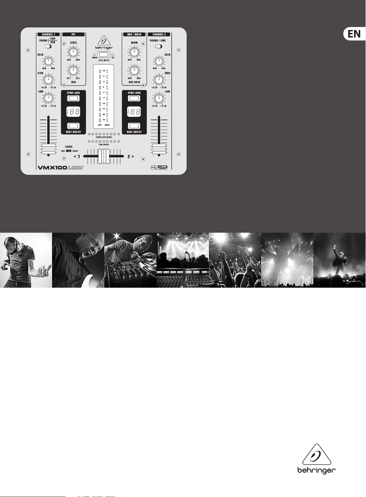
PRO MIXER VMX100USB
Professional 2-Channel DJ Mixer with USB/Audio Interface,
BPM Counter and VCA Control
Page 2

2 PRO MIXER VMX100USB User Manual
Table of Contents
Thank you .......................................................................2
Important Safety Instructions ...................................... 3
Legal Disclaimer ............................................................. 3
Limited warranty ............................................................ 3
1. Introduction ............................................................... 4
1.1 Before you get started ...................................................... 4
2. Front Panel ................................................................. 4
2.1 Input channels 1 and 2 ..................................................... 5
2.2 PFL section (Pre Fader Listening) .................................. 5
2.3 Mic/Main section ................................................................ 5
2.4 Beat counter ......................................................................... 5
2.5 Crossfader section .............................................................. 5
3. Rear Panel................................................................... 6
4. Specications ............................................................. 7
Thank you
With the BEHRINGER PRO MIXER VMX100USB, you have purchased an
absolutely state-of-the-art DJ mixer. Its extensive features open the door to
new and creative ways of working, while making it suitable for a variety of
professional applications. At the same time, the VMX100USB is extremely easy
to operate, allowing you to completely unfold your creativity.
Time waits for no one, and neither you nor we want to be left behind. That’s why
we invested months of research and development in creating a DJ mixer that
oers up-to-date features and technology to give you a true cutting edge for
your performances. Fully optimized for dance club applications and DJ systems,
the VMX100USB promises full-blown DJ’ing fun—and success.
Let’s be honest: nobody likes reading users’ manuals. We know you want to plug
in and get jammin’, but please take the time to read the following instructions.
We’ve kept them as short as possible, and it will be well worth the few minutes
it takes you. Armed with a thorough understanding of the VMX100USB’s features
and functions, you’ll be able to get the most out of this exciting product.
Page 3
3 PRO MIXER VMX100USB User Manual
9. Do not defeat the safety purpose of the polarized
or statement contained herein. Technical speci cations,
Important Safety Instructions
Terminals marked with this symbol carry
electrical current of su cient magnitude
to constitute risk of electric shock.
Use only high-quality professional speaker cables with
¼" TS or twist-locking plugs pre-installed. Allother
installation or modi cation should be performed only
by quali edpersonnel.
This symbol, wherever it appears,
alertsyou to the presence of uninsulated
dangerous voltage inside the
enclosure-voltage that may be su cient to constitute a
risk ofshock.
This symbol, wherever it appears,
alertsyou to important operating and
maintenance instructions in the
accompanying literature. Please read the manual.
Caution
To reduce the risk of electric shock, donot
remove the top cover (or the rear section).
No user serviceable parts inside. Refer servicing to
quali ed personnel.
Caution
To reduce the risk of re or electric shock,
do not expose this appliance to rain and
moisture. The apparatus shall not be exposed to dripping
or splashing liquids and no objects lled with liquids,
suchas vases, shall be placed on the apparatus.
Caution
These service instructions are for use
by quali ed ser vice personnel only.
Toreduce the risk of electric shock do not perform any
servicing other than that contained in the operation
instructions. Repairs have to be performed by quali ed
servicepersonnel.
1. Read these instructions.
2. Keep these instructions.
3. Heed all warnings.
4. Follow all instructions.
5. Do not use this apparatus near water.
6. Clean only with dry cloth.
7. Do not block any ventilation openings. Install in
accordance with the manufacturer’s instructions.
8. Do not install near any heat sources such as
radiators, heat registers, stoves, or other apparatus
(including ampli ers) that produce heat.
or grounding-type plug. A polarized plug has two blades
with one wider than the other. A grounding-type plug
has two blades and a third grounding prong. The wide
blade or the third prong are provided for your safety. Ifthe
provided plug does not t into your outlet, consult an
electrician for replacement of the obsolete outlet.
10. Protect the power cord from being walked on or
pinched particularly at plugs, convenience receptacles,
and the point where they exit from the apparatus.
11. Use only attachments/accessories speci ed by
themanufacturer.
12. Use only with the
cart, stand, tripod, bracket,
or table speci ed by the
manufacturer, orsold with
the apparatus. When a cart
is used, use caution when
moving the cart/apparatus
combination to avoid
injury from tip-over.
13. Unplug this apparatus during lightning storms or
when unused for long periods of time.
14. Refer all servicing to quali ed service personnel.
Servicing is required when the apparatus has been
damaged in any way, such as power supply cord or plug
is damaged, liquid has been spilled or objects have fallen
into the apparatus, the apparatus has been exposed
to rain or moisture, does not operate normally, or has
beendropped.
15. The apparatus shall be connected to a MAINS socket
outlet with a protective earthing connection.
16. Where the MAINS plug or an appliance coupler is
used as the disconnect device, the disconnect device shall
remain readily operable.
17. Correct disposal of this
product: This symbol indicates
that this product must not be
disposed of with household
waste, according to the WEEE
Directive (2012/19/EU) and
your national law. This product
should be taken to a collection center licensed for the
recycling of waste electrical and electronic equipment
(EEE). The mishandling of this type of waste could have
a possible negative impact on the environment and
human health due to potentially hazardous substances
that are generally associated with EEE. At the same time,
your cooperation in the correct disposal of this product
will contribute to the e cient use of natural resources.
For more information about where you can take your
waste equipment for recycling, please contact your local
city o ce, or your household waste collection service.
LEGAL DISCLAIMER
MUSIC Group accepts no liability for any loss which
may be su ered by any person who relies either
wholly or in part upon any description, photograph,
appearances and other information are subject to
change without notice. All trademarks are the property
of their respective owners. MIDAS, KLARK TEKNIK,
TURBOSOUND, BEHRINGER, BUGERA and DDA are
trademarks or registered trademarks of MUSIC Group IP
Ltd. © MUSIC Group IP Ltd. 2015 All rights reserved.
LIMITED WARRANTY
For the applicable warranty terms and conditions
and additional information regarding MUSIC Group’s
Limited Warranty, please see complete details online at
music-group.com/warranty.
Page 4

4 PRO MIXER VMX100USB User Manual
1. Introduction
◊ The following instructions will give you a brief run-down on the
terminology and functions of the VMX100USB. After reading,
please store this manual in a safe place for future reference.
1.1 Before you get started
Your PRO MIXER was carefully packed in the factory and the
packaging is designed to protect the unit against rough handling.
Nevertheless, we recommend that you carefully examine packaging and contents
for any signs of physical damage which may have occurred during transit.
◊ If the unit is damaged, please do not return it to BEHRINGER,
but notify your dealer and the shipping company immediately.
Otherwise, claims for damage or replacement may not be granted.
Shipping claims must be made by the consignee.
◊ If the unit needs to be shipped, please always use the original
packaging to avoid damage.
2. Front Panel
(1)
(5)
◊ Never let unsupervised children play with the VMX100USB or
with its packaging.
◊ Please dispose of all packaging materials in an environmentally-
friendly fashion.
Please take care to always ensure adequate ventilation. Do not place
the PRO MIXER near heating units or heat-generating devices in order to
avoid overheating.
CAUTION!
◊ We would like to point out that high volumes can permanently damage
your sense of hearing and/or your headphone or speaker systems.
Therefore, please turn the MAIN control in the MIC/MAIN section all the
way to the left before turning on the mixer. And please exercise caution
and common sense when setting volume levels.
(9)
(2)
(6)
(3)
(4)
(17)
(8)
(10)
(7)
(12)
(11)
(13)
(14)
(15)
(16)
(18)
Fig. 2.1 Front view of t he PRO MIXER VMX100USB
(19)
Page 5

5 PRO MIXER VMX100USB User Manual
2.1 Input channels 1 and 2
(1) The PHONO/LINE-USB switch selects one of the input pairs on the
respective channel. The “PHONO” setting (and inputs) are intended for
turntables; for all other signal sources, i.e. a CD or MD player, use the “LINE”
setting and inputs. Audio sent from a computer to the VMX via USB cable is
routed to channel 1. This signal is mixed with the LINE input.
◊ Never connect line-level equipment to the highly sensitive phono
inputs! The output levels of phono cartridge systems are in the
millivolt range, whereas CD and MD players, as well as tape decks,
provide outputs levels in the volt range. In other words, the level of line
signals is up to 100 times higher than phono output levels.
(2) The GAIN control is used to adjust the input signal level.
◊ The overall level of your signal is also effected by the EQ settings.
It’s a good idea to adjust the equalizer before you set the level with the
GAIN control.
(3) Each of the two input channels is equipped with a 2-BAND EQUALIZER
with kill characteristic. The maximum amount of attenuation (-32 dB) is
much higher than the maximum boost (+12 dB), allowing entire frequency
spectrums to be “removed” from a track.
(4) The CHANNEL fader adjusts the nal channel volume.
2.2 PFL section (Pre Fader Listening)
The PFL signal is a pre-fader headphones signal, enabling you to pre-listen to a
signal source without eecting the main signal.
(5) The LEVEL control determines the volume of the headphones signal.
(6) The MIX control lets you fade between channels 1 and 2.
(7) The LEVEL METER displays the level of the signal selected via the
MAIN/PFL button ((8)).
Once the tempo of the two tracks have been determined and locked with the
SYNC LOCK or BEAT ASSIST buttons, the tempo dierence between channel 1
and 2 will be depicted via the 9-segment TEMPO DIFFERENCE LED display ((14)).
It shows the degree of the tempo dierence by a respective deection to the
right (channel 2 track is faster) or to the left (channel 2 track is faster). The center
LED lights when the tempi are equal. The synchronization of channel 1 and 2 is
shown in the TIME OFFSET LED display ((15)) below the TEMPO DIFFERENCE display.
When the center LED is lit, the tracks are in sync with each other. When the
display moves to the left or right, the corresponding channel is running out of
sync. The TEMPO DIFFERENCE and TIME OFFSET displays are only active when the
tempi of both channels have been locked as explained above.
To exit the SYNC LOCK or BEAT ASSIST mode, simply press the SYNC LOCK key in
both channels again.
2.5 Crossfader section
(16) The CROSSFADER is used to fade between channels 1 and 2.
(17) The CURVE switch, located on the left side of the CROSSFADER, enables you
to select between two crossfade modes: SOFT and SHARP. In SOFT mode
the crossfader fades between the channels in a linear, continuous manner.
This mode is recommended for slower, smoother crossfades. In SHARP
mode the crossfader takes on a more logarithmic eect, working faster
towards the outer edges of the fader range. Use this mode for faster,
“hard” crossfades.
◊ Flipping the CURVE switch may cause a sudden change in volume.
We recommend not changing this setting while a signal is present.
(18) The MIC INPUT connector is a balanced ¼" TRS socket for
microphone connection.
◊ We strongly recommend the use of high-grade cables and connectors
for the transmission of audio signals. Inferior quality materials cannot
supply acceptable audio quality or corrosion protection.
(8) The MAIN/PFL button allows you to route either the main or PFL signal to
the display. Remember: “PFL” is your pre-listening or headphone signal and
“MAIN” is the signal assigned to the outputs of the VMX100USB.
◊ In PFL mode, the channel 1 signal is displayed on the left side of the
LEVEL METER, and channel 2 on the right.
2.3 Mic/Main section
(9) The MAIN knob controls the overall output volume.
(10) The MIC LEVEL control adjusts the volume of the microphone signal.
2.4 Beat counter
The PRO MIXER VMX100USB’s built-in beat counter is an extremely useful feature,
allowing smooth crossfades between two tracks—an important key to the
success of your performance. The beat counter analyzes and displays the tempi
of your tracks in BPM (Beats Per Minute). The beat counter sections of channel
1 and 2 are identical.
The tempo of the track is shown in the respective channel’s Display ((11)).
In the case of multiple tempo changes, the display would change continuously,
causing unnecessar y confusion and rendering the function virtually useless.
Enter the SYNC LOCK button ((12)): with it, you can limit the range of possible
tempo values within a song. Pressing this button once the counter has “caught”
and displayed a realistic value will simplify things. The BEAT ASSIST button ((13))
allows you to set the beat counter’s tempo manually, similar to“tap tempo”.
Pressing the button three times in time with the track will set the beat counter
and its display at that tempo. The BEAT ASSIST and SYNC LOCK buttons are each
equipped with an LED to show that the respective function is activated.
(19) The HEADPHONES socket allows you to connect your headphones for
pre-listening (PFL signal). For best results, use headphones with an
impedance rating of at least 32 Ohms.
Page 6

6 PRO MIXER VMX100USB User Manual
3. Rear Panel
With the exception of MIC INPUT and HEADPHONES, all of the VMX100USB’s audio
connections are located on the rear panel and supplied as RCA connectors.
(23)
(24) (20) (21) (28)
(26)
(29)
(25)(27)
Fig 3.1: Rear view of the PRO MIXE R VMX100USB
(22)
(20) The PHONO inputs for channel 1 and 2 are only for turntable connection.
(21) The LINE inputs may be used for connecting tape decks, CD or
MD players etc.
(22) The GND connection allows grounding of a turntable.
(23) Use the AMP output to connect the VMX100USB to an amplier. The level is
controlled by the MAIN knob in the MIC/MAIN section.
◊ In order to avoid power-up thumps, which can damage your
loudspeakers, please power up your amplifier last. There should be no
signal present, e.g. no music playing, when you turn on your amp. In
addition, we suggest that you set all volume-related controls to “zero”
(down) before powering up your system. Following these precautions
will save you from unpleasant and potentially dangerous surprises.
(24) The TAPE output enables you to record your performance by connecting a
tape deck, DAT recorder etc. Unlike the AMP output, the TAPE level is xed,
so that you have to adjust the input level on the recorder.
(25) The POWER ON switch turns on the PRO MIXER.
(26) FUSE HOLDER/VOLTAGE SELECTOR. Before you connect the equipment to
an AC outlet, please be sure that the voltage displayed corresponds with your
local AC voltage. If you should need to replace the fuse, be sure to replace
it with one of the same type and value. Some units allow you to switch
between 240 V and 120 V by rotating the fuse holder.
(28) SERIAL NUMBER. Please take the time to ll out and return the warranty
card within 14 days after the date of purchase. This will entitle you to all the
benets of our extended warranty. Alternatively, you can register online at
behringer.com.
(29) The VMX has built-in USB connectivity, allowing stereo signals to be sent
to and from the mixer and a computer. The audio sent from the mixer
to a computer is identical to the TAPE OUT signal, which is the pre-fader
MAIN signal. Audio being sent from a computer to the VMX can be selected
with the Channel 1 PHONO/LINE-USB switch.
Connect a USB type B plug into the USB jack on the mixer, and the other end
into a free USB port on your computer. There are no required drivers, but we
recommend that PC users install the included ASIO driver. The driver can also be
downloaded from behringer.com.
◊ To operate the unit at 120 V, you must install a fuse with the double
ampere rating.
(27) This is the socket for the power cable. The impulse behavior of any given
amplier circuit depends largely upon the power supply’s inherent reserves.
All mixers contain numerous operational ampliers (op-amps) for processing
line-level signals. Due to the restricted performance of their power supplies,
many mixers show “stress symptoms” when used under ex treme conditions,
resulting in inferior audio quality. Thanks to its generously proportioned
power supply, this will never happen to your VMX100USB: The sound will
always be clear, transparent and powerful.
Page 7

7 PRO MIXER VMX100USB User Manual
4. Specications
Audio Inputs
Mic input 53 dB gain, servo-balanced
Phono inputs 1 and 2 40 dB gain @ 1 kHz, unbalanced
Line inputs 1 and 2 0 dB gain, unbalanced
Audio Ouputs
Main Out max. +21 dBu @ +15 dBu (LINE IN)
Tape Out typically 0 dBu
Headphones typically 125 mW @ 1% THD
Equalizer
Stereo Low +12 dB/-32 dB @ 50 Hz
Stereo High +12 dB/-32 dB @ 10 kHz
General
Signal-to-noise ratio (S/N) > 88 dB (Line)
Crosstalk > 67 dB (Line)
Distortion (THD) < 0.025%
Frequency response 20 Hz - 20 kHz
Input gain adjustment -20 dB - +9 dB
USB
Audio Stereo In/Out
Connector Type B
Converter 16-bit
Sample rate 48 kHz
Power Supply
Mains voltages
USA/Canada 120 V~, 60 Hz
Europe/U.K./Australia 230 V~, 50 Hz
Japan 100 V~, 50 - 60 Hz
General export model 120/230 V~, 50 - 60 Hz
Power consumption max. 10 W
Fuse 100 - 120 V~: T 160 mA L 250 V
200 - 240 V~: T 80 mA L 250 V
Mains connection Standard IEC receptacle
Dimensions and Weight
Dimensions (H x W x D) approx. 72 x 203 x 229 mm
(2.8 x 8.0 x 9.0")
Weight approx. 2 kg (4.4 lbs)
BEHRINGER i s constantly str iving to maintain the h ighest profess ional standards. A s a result of these e ffort s,
modific ations may be made f rom time to time to exi sting product s without prio r notice. Specif ications and
appearance m ay differ fro m those listed or illus trated.
Page 8

8 PRO MIXER VMX100USB User Manual
FEDERAL COMMUNICATIONS
COMMISSION COMPLIANCE
INFORMATION
PRO MIXER VMX100USB
Responsible Party Name: MUSIC Group Services NV Inc.
Address: 5270 Procyon Street
Las Vegas, NV 89118
USA
Phone Number: +1 702 800 8290
PRO MIXER VMX100USB
complies with the FCC rules as mentioned in the followingparagraph:
This equipment has been tested and found to comply with the limits for a ClassB
digital device, pur suant to part 15 of the FCC Rules. These limits are designed
to provide reasonable protection against harmful interference in a residential
installation. This equipment generates, uses and can radiate radio frequency
energy and, if not installed and used in accordance with the instructions, may cause
harmful interference to radio communications. However, there is no guarantee that
interference will not occur in a par ticular installation. If this equipment does cause
harmful interference to radio or television reception, which can be determined
by turning the equipment o and on, the user is encouraged to try to correct the
interference by one or more of the followingmeasures:
• Reorient or relocate the receiving antenna.
• Increase the separation between the equipment and receiver.
• Connect the equipment into an outlet on a circuit dierent from that to which the
receiver is connected.
• Consult the dealer or an experienced radio/TV technician forhelp.
This device complies with Part 15 of the FCC rules. Operation is subjec t to the
following two conditions:
(1) this device may not cause harmful interference, and
(2) this device must accept any inter ference received, including inter ference that may
cause undesired operation.
Important information:
Changes or modications to the equipment not expressly approved by MUSIC Group
can void the user’s authority to use the equipment.
Page 9

We Hear You
 Loading...