

Page 1
Users Manual
Version 1.2 August 2002
ENGLISH
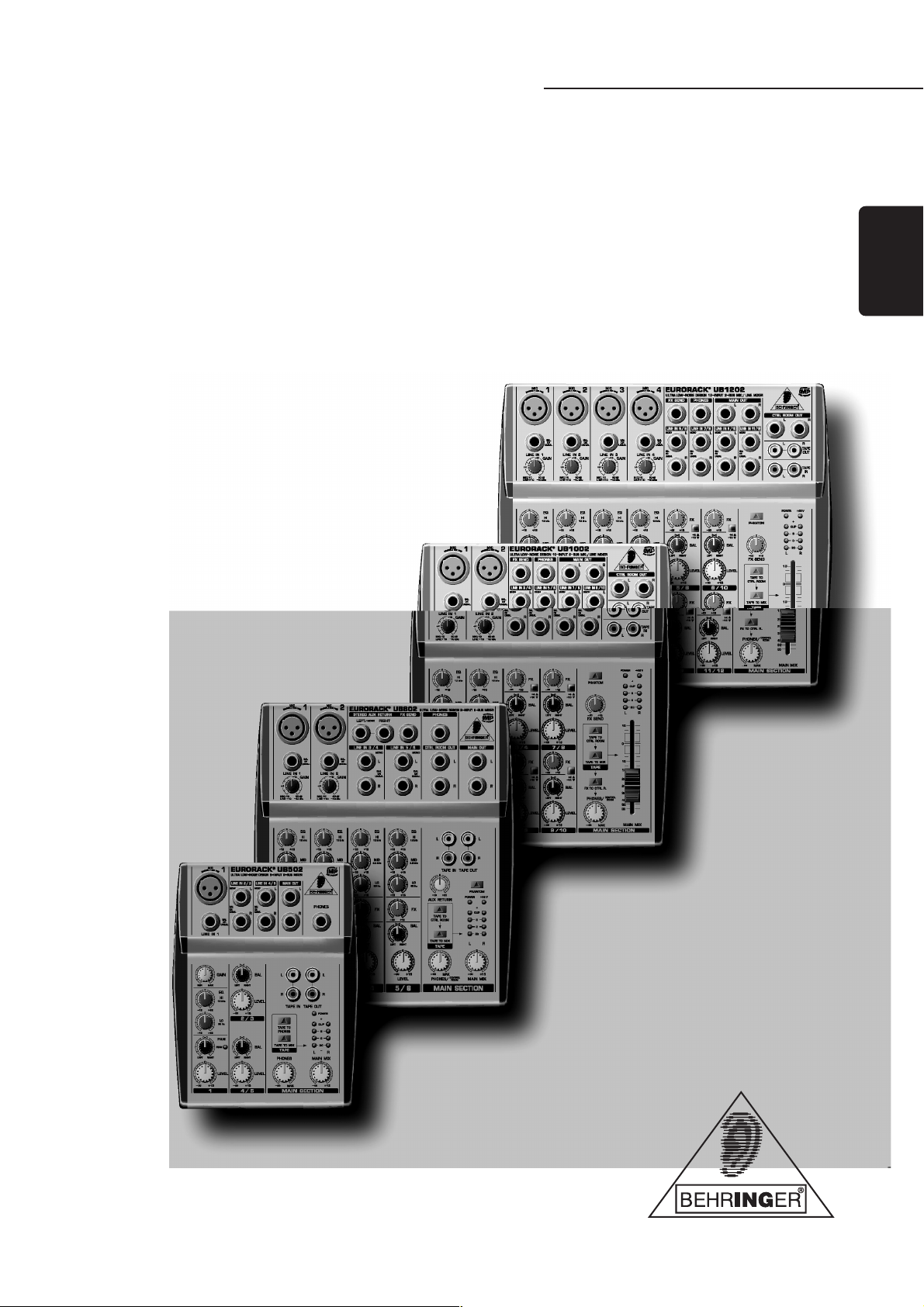
UB502/UB802/UB1002/UB1202
®
EURORACK
www.behringer.com
Page 2

EURORACK UB502/UB802/UB1002/UB1202
SAFETY INSTRUCTIONS
CAUTION: To reduce the risk of electric shock, do not remove
the cover (or back). No user serviceable parts
inside; refer servicing to qualified personnel.
WARNING: To reduce the risk of fire or electric shock, do not
expose this device to rain and moisture.
This symbol, wherever it appears, alerts you to the
presence of uninsulated dangerous voltage inside
the enclosurevoltage that may be sufficient to
constitute a risk of shock.
This symbol, wherever it appears, alerts you to
important operating and maintenance instructions
in the accompanying literature. Please read the
manual.
DETAILED SAFETY INSTRUCTIONS:
All the safety and operation instructions should be read before
the device is operated.
Retain Instructions:
The safety and operating instructions should be retained for
future reference.
Heed Warnings:
All warnings on the device and in the operating instructions
should be adhered to.
Follow instructions:
All operation and user instructions should be followed.
Water and Moisture:
The device should not be used near water (e.g. near a bathtub,
washbowl, kitchen sink, laundry tub, in a wet basement, near a
swimming pool etc.).
Ventilation:
The device should be situated so that its location or position
does not interfere with its proper ventilation. For example, the
device should not be placed on a bed, sofa, rug, or similar surface
that may block the ventilation openings, or used in a built-in
installation, such as a bookcase or cabinet that may impede the
flow of air through the ventilation openings.
Heat:
The device should be situated away from heat sources such
as radiators, heat registers, stoves, or other devices (including
amplifiers) that produce heat.
Power Source:
The device should only be connected to a power supply of the
type described in the operating instructions or on the device.
Grounding or Polarization:
This device must be grounded.
Power Cords:
Power cords should be routed so that they are not likely to be
walked on or pinched by items placed upon or against them,
paying particular attention to cords and plugs, sockets, outlets
and the point where they exit from the device.
Cleaning:
The device should be cleaned only as recommended by the
manufacturer.
Non-use Periods:
The power cord of the device should be unplugged from the
outlet when left unused for a long period of time.
Debris and Liquid Entry:
Debris and/or liquids should not be allowed to enter the
enclosure through openings.
Damage Requiring Service:
The device should be serviced by qualified service personnel
when:
s The power cord or the plug has been damaged; or
s Debris or liquid has entered the device; or
s The device has been exposed to rain; or
s The device does not appear to operate normally or exhibits
a pronounced change in performance; or
s The device has been dropped, or the enclosure damaged.
Servicing:
The user should not attempt to service the device beyond that
which is described in the operating instructions. All other
servicing should be referred to qualified service personnel.
2
Page 3

EURORACK UB502/UB802/UB1002/UB1202
TABLE OF CONTENTS
1. INTRODUCTION ......................................................................................................... 4
1.1 General mixing console functions .................................................................................................................... 4
1.2 The users manual ............................................................................................................................................ 4
1.3 Before you get started ....................................................................................................................................... 5
1.3.1 Shipment .................................................................................................................................................. 5
1.3.2 Initial operation ........................................................................................................................................ 5
1.3.3 Warranty ................................................................................................................................................... 5
2. CONTROL ELEMENTS AND CONNECTORS .......................................................... 5
2.1 Mono channels .................................................................................................................................................. 5
2.1.1 Microphone and line inputs ..................................................................................................................... 5
2.1.2 Equalizer .................................................................................................................................................. 5
2.1.3 FX sends, panorama and level adjustment ............................................................................................ 6
2.2 Stereo channels ................................................................................................................................................ 6
2.2.1 Stereo line inputs ..................................................................................................................................... 6
2.2.2 Equalizer stereo channels (UB802) ........................................................................................................ 6
2.2.3 FX sends, balance and level adjustment ................................................................................................ 6
2.3 Connector panel and main section .................................................................................................................. 6
2.3.1 Send/return effects path ........................................................................................................................... 6
2.3.2 Monitor and main mix .............................................................................................................................. 7
2.3.3 Tape connectors ...................................................................................................................................... 7
2.3.4 Signal assignment .................................................................................................................................. 7
2.3.5 Phantom power and LED displays ......................................................................................................... 7
3. INSTALLATION .......................................................................................................... 8
3.1 Mains connection .............................................................................................................................................. 8
3.2 Audio connections ............................................................................................................................................. 8
4. SPECIFICATIONS ...................................................................................................... 9
5. WARRANTY ............................................................................................................. 10
3
Page 4

EURORACK UB502/UB802/UB1002/UB1202
FOREWORD
Dear Customer,
Im sure youre one of
those people who have
devoted themselves body
and soul to your chosen
area and no doubt this has
transformed you into an
expert in your field!
Well, for over 30 years,
my passion has been
music and electronics.
This not only led me to
establish BEHRINGER,
but also enabled me to
convey and share my
enthusiasm with my
employees.
During all the years Ive
been involved with
studio technology and
end users, I have developed a feel for the things that really
count, such as sound quality, reliability and ease of use. Whats
more, I have always had the desire to push the boundaries of
technical possibilities to the extreme.
It was precisely this motivation that prompted me to start work
on a new series of mixing consoles. Since our EURORACKs had
already set new standards world-wide, I knew the development
objectives behind the products bearing my initials had to be
especially ambitious.
Thus, the concept and design of the new UB mixing consoles
bear my signature. The design work, the entire circuit diagram
and PCB development, and even the mechanical concepts are
my own work. I carefully selected each individual component
with the aim of pushing the mixing consoles analog and digital
technologies to their limits.
My vision was to enable you, the user, to give free rein to your
true potential and creativity. The result is incredibly powerful mixing
consoles that offer intuitive operation. They cannot fail to impress
with their extremely flexible routing possibilities plus fantastic wealth
of functions. Innovative technologies, such as the completely new
IMP Invisible Mic Preamps, guarantee optimum sound quality.
And extraordinarily high-quality components provide unrivalled
reliability, even under extreme loads.
Your new UB mixing console is of high quality yet is simple to
use; youll soon appreciate that I, both personally and in my
capacity as musician and sound engineer, put you, the end user,
first and that these products were only possible because of the
passion and the attention to detail that went into them.
Thank you for the confidence you have placed in us by
purchasing the UB mixing console. I should also like to thank all
those who, with their personal commitment and passion, have
helped me realize this impressive series of mixing consoles.
1. INTRODUCTION
Congratulations! In purchasing our EURORACK UB502/UB802/
UB1002/UB1202 you have acquired a mixing console whose
small size belies its incredible versatility and audio performance.
The range of inputs and outputs comprises microphone inputs
(with +48 V phantom power supply, except UB502), line inputs,
possibilities for connecting effects devices, connectors for a 2track master machine (e.g. DAT recorder) and a monitor system
consisting of monitor loudspeaker(s) and power amplifier (except
for UB502).
IMP INVISIBLE MIC PREAMP
The microphone channels are fitted with BEHRINGERs brand
new premium quality IMP INVISIBLE MIC PREAMPs that boast the
following features:
s 130 dB dynamic range for an incredible amount of headroom
s A bandwidth ranging from below 10 Hz to over 200 kHz for
crystal-clear reproduction of even the finest nuances
s The extremely low-noise and distortionfree circuitry gua-
rantees absolutely natural and transparent signal reproduction
s They are perfectly matched to every conceivable micro-
phone with up to 60 dB gain and +48 volt phantom power
supply (UB502: no phantom power)
s They enable full utilisation of the greatly extended dynamic
range of your 24-bit/192 kHz HD recorder, thereby maintaining optimal audio quality
CAUTION!
+ We should like to draw your attention to the fact
that extreme volumes may damage your hearing
and/or your headphones or loudspeakers. Turn the
MAIN MIX control and PHONES control in the main
section fully counter-clockwise before you switch
on the unit. Always be careful to set appropriate
volume levels.
1.1 General mixing console functions
A mixing console fulfils three main functions:
s Signal processing: Preamplification, level adjustment,
mixing of effects, frequency equalization.
s Signal distribution: Summing of signals to the aux sends
for effects processing and monitor mix, distribution to one
or several recording tracks, power amp(s), control room
and 2-track outputs.
s Mix: Setting the volume level, frequency distribution and
positioning of the individual signals in the stereo field, level
control of the total mix to match the recording devices/
crossover/power amplifier(s). All other mixer functions can
be included in this main function.
The interface of BEHRINGER mixing consoles is optimized for
these tasks enabling you to easily keep track of the signal path.
Kindest regards,
Uli Behringer
4
1.2 The users manual
The users manual is designed to give you both an overview of
the controls, as well as detailed information on how to use them.
In order to help you understand the links between the controls,
we have arranged them in groups according to their function.
The illustrations at the beginning of each chapter show the
controls described in each respective chapter.
+ The block diagram supplied with the mixing console
gives you an overview of the connections between
the inputs and outputs, as well as the associated
switches and controls.
1. INTRODUCTION
Page 5

EURORACK UB502/UB802/UB1002/UB1202
For the moment, just try and trace the signal path from the
microphone input to the FX send connector. Dont be put off by
the huge range of possibilities; its easier than you think! If you
look at the overview of the controls at the same time, youll be
able to quickly familiarize yourself with your mixing console and
youll soon be making the most of all its many possibilities.
If you need to know more about specific issues, please visit
our website at http://www.behringer.com, where youll find
explanations of (for example) effects and dynamics applications.
1.3 Before you get started
1.3.1 Shipment
Your mixing console was carefully packed in the factory to
guarantee safe transport. Nevertheless, we recommend that
you carefully examine the packaging and its contents for any
signs of physical damage, which may have occurred during
transit.
+ If the unit is damaged, please do NOT return it to us,
but notify your dealer and the shipping company
immediately, otherwise claims for damage or
replacement may not be granted.
1.3.2 Initial operation
Be sure that there is enough space around the unit for cooling
purposes and to avoid over-heating please do not place your
mixing console on high-temperature devices such as radiators
or power amps. The console is connected to the mains via the
supplied cable. The console meets the required safety standards.
Blown fuses must only be replaced by fuses of the same type
and rating.
+ Never connect the EURORACK to the power supply
unit when the latter is connected to the mains!
First connect the power supply unit to the console,
then connect the power supply unit to the mains.
+ Please note that all units must be properly
grounded. For your own safety, you should never
remove any ground connectors from electrical
devices or power cables, or render them inoperative.
+ Please ensure that only qualified people install and
operate the mixing console. During installation and
operation, the user must have sufficient electrical
contact to earth, otherwise electrostatic discharges
might affect the operation of the unit.
2.1 Mono channels
2.1.1 Microphone and line inputs
Fig. 2.1: Connectors and controls of mic/line inputs
MIC
Each mono input channel offers a balanced microphone input
via the XLR connector and also features a switchable +48V
phantom power supply for condenser microphones. Please note:
the EURORACK UB502 does not supply phantom power.
+ Please mute your playback system before you
activate the phantom power supply to prevent
switch-on thumps being directed to your
loudspeakers. Please also note the instructions
in chapter 2.3.5 Phantom power and LED displays.
LINE IN
Each mono input also features a balanced line input on a 1/4"
connector. Unbalanced devices (mono jacks) can also be
connected to these inputs.
+ Please remember that you can only use either the
microphone or the line input of a channel at any
one time. You can never use both simultaneously!
GAIN
Use the GAIN control to adjust the input gain. This control
should always be turned fully counterclockwise whenever you
connect or disconnect a signal source to one of the inputs.
2.1.2 Equalizer
All mono input channels include a 3-band equalizer, except for
the UB502, which is equipped with a 2-band EQ. All bands provide
boost or cut of up to 15 dB. In the central position, the equalizer
is inactive.
1.3.3 Warranty
Please take time to fill out and return the warranty card within
14 days after the date of purchase, so as to be entitled to benefit
from our extended warranty. Alternatively, you can use our
online registration option available on the world wide web
(www.behringer.com). You will find the serial number on the
rear of your mixing console.
2. CONTROL ELEMENTS AND
CONNECTORS
This chapter describes the various control elements of your
mixing console. All controls, switches and connectors will be
discussed in detail.
2. CONTROL ELEMENTS AND CONNECTORS
Fig. 2.2: The equalizer of the mono input channels
EQ
The upper (HI) and the lower band (LO) are shelving filters
that increase or decrease all frequencies above or below their
cut-off frequency. The cut-off frequencies of the upper and
lower band are 12 kHz and 80Hz respectively. The mid band
(UB802/UB1002/UB1202) is configured as a peak filter with a
center frequency of 2.5 kHz.
LO CUT
In addition, the mono channels (UB1002 and UB1202) are
equipped with a steep LO CUT filter (slope at 18 dB/oct., -3 dB
at 75 Hz) designed to eliminate unwanted low-frequency signal
components.
5
Page 6

EURORACK UB502/UB802/UB1002/UB1202
2.1.3 FX sends, panorama and level adjustment
6
Page 7

EURORACK UB502/UB802/UB1002/UB1202
device will then have to be brought back into the console via a
normal stereo channel. This does, however, give you the ability
to use the channel EQ on the effects return signal if you wish.
+ When using a stereo channel as effects return path,
the FX control of the relevant channel should
generally be turned fully down to avoid undesirable
feedback.
If only the left connector is used, the AUX RETURN automatically
operates in mono. Use the AUX RET(URN) control to determine
how much of the effects signal is sent to the main mix.
FX SEND
The FX SEND output (does not apply for UB502) should be
connected to the input of an external effects unit. The postfader FX signal you created using the input channel FX controls
is sent to the effects unit via the FX SEND ouput. Use the FX
SEND control of the main section to adjust the overall send level
(UB1002 and UB1202 only).
2.3.2 Monitor and main mix
Alternatively the line or tape output of a hi-fi amplifier with
source selection switch could also be hooked up here, allowing
you to easily listen to additional sources.
TAPE OUTPUT
These connectors are wired in parallel with the MAIN OUT and
carry the main mix signal (unbalanced). Connect the TAPE
OUTPUT to the inputs of your recording device. The output level
is adjusted via the high-precision MAIN MIX fader or rotary
control (UB802).
Fig. 2.11: Tape input/output
2.3.4 Signal assignment
Fig. 2.9: Monitor/main mix connectors
Fig. 2.10: Monitor control and main mix fader
PHONES/CONTROL ROOM
The stereo PHONES jack (at the top of the connector panel) is
where you connect headphones. The unbalanced CONTROL
ROOM OUT jacks carry the summed effects and main mix signals,
as well as soloed channel signals. The PHONES/CONTROL ROOM
control adjusts the level of both headphones and main monitor
outputs. The UB502 is not equipped with control room outputs.
MAIN MIX
The MAIN OUT connectors are unbalanced mono jacks. The
main mix signal appears here at a level of 0 dBu. The MAIN MIX
fader adjusts the volume of these outputs. The EURORACK UB802
and UB502 mixing consoles feature a rotary control for this purpose.
2.3.3 Tape connectors
TAPE INPUT
The TAPE INPUTs are used to bring an external signal source
(e.g. CD player, tape deck, etc.) into the console. They can also
be used as a standard stereo line input, so the output of a
second EURORACK or BEHRINGER ULTRALINK PRO MX882 can
be connected.
7
Page 8

EURORACK UB502/UB802/UB1002/UB1202
+48 V (UB802/UB1002/UB1202 only)
The red +48 V LED lights up when phantom power is on. The
PHANTOM switch activates the phantom power supply on the
XLR connectors of all mono channels.
+ Please do not connect microphones to the mixer
(or the stagebox/wallbox) as long as the phantom
power supply is switched on. Connect the microphones before you switch on the power supply. In
addition, the monitor/PA loudspeakers should be
muted before you activate the phantom power
supply. After switching on, wait approx. one minute
in order to allow system stabilization.
POWER
The blue POWER LED indicates that the console is powered on.
LEVEL INDICATOR
The high-precision 4-segment display accurately displays the
relevant signal level.
LEVEL SETTING:
To correctly set the gains of the channels, first set the LEVEL
controls of the input channels to their center positions (0 dB).
Then use the GAIN controls to increase the input amplification
until signal peaks show 0 dB on the level meter.
When recording to digital recorders, the recorders peak meter
should not go into overload. While analog recorders can be
overloaded to some extent, creating only a certain amount of distortion
(which is common and often desirable), digital recorders distort
quickly when overloaded. In addition, digital distortion is not only
undesirable, but also renders your recording completely useless.
+ Caution! Never use unbalanced XLR connectors
(PIN 1 and 3 connected) on the MIC input connectors
when using the phantom power supply.
+ The peak meters of your EURORACK display the level
virtually independent of frequency. A recording level
of 0 dB is recommended for all signal types.
3. INSTALLATION
3.1 Mains connection
AC POWER IN
Connect the power supply to the 3-pin mains connector on the
rear of the console. Use the AC adapter supplied to connect the
console to the mains. The adapter complies with all applicable
safety standards.
+ Please use only the power supply unit provided
with the console.
+ Never connect the EURORACK to the power supply
unit while the latter is connected to the mains! First
connect the console to the power supply unit, then
connect the power supply unit to the mains.
+ Please note that both the power supply unit and
the mixing console heat up considerably during
operation. This is completely normal.
3.2 Audio connections
You will need a large number of cables for different
applications. The illustrations below show how the connectors
should be wired. Be sure to use only high-grade cables.
Please use commercial RCA cables to connect the 2-track
inputs and outputs.
You can, of course, also connect unbalanced devices to the
balanced inputs/outputs. To do this, use either mono plugs or
stereo plugs with the ring and sleeve bridged (pins 1 and 3 in the
case of XLR connectors).
8
Page 9

EURORACK UB502/UB802/UB1002/UB1202
4. SPECIFICATIONS
Mono inputs
Microphone inputs (IMP Invisible Mic Preamp)
Type XLR, electronically balanced,
Mic E.I.N. (20 Hz - 20 kHz)
@ 0 Ω source resistance -134 dB / 135.7 dB A-weighted
@ 50 Ω source resistance -131 dB / 133.3 dB A-weighted
@ 150 Ω source resistance -129 dB / 130.5 dB A-weighted
Frequency response <10 Hz - 150 kHz (-1 dB),
Gain range +10 to +60 dB
Max. input level +12 dBu @ +10 dB gain
Impedance approx. 2.6 kΩ balanced
Signal-to-noise ratio 110 dB / 112 dB A-weighted
Distortion (THD+N) 0.005% / 0.004% A-weighted
Line input
Type 1/4" TRS connector
Impedance approx. 20 kΩ balanced
Gain range -10 to +40 dB
Max. input level 30 dBu
Fade-out attenuation
(Crosstalk attenuation)
Main fader closed 90 dB
Channel muted 89.5 dB
Channel fader closed 89 dB
Frequency response
Microphone input to main out
<10 Hz - 90 kHz +0 dB / -1 dB
<10 Hz - 160 kHz +0 dB / -3 dB
Stereo inputs
Type 1/4" TRS connector,
Impedance approx. 20 kΩ
Max. input level +22 dBu
EQ mono channels
L o w 80 Hz / ±15 dB
Mid 2.5 kHz / ±15 dB
High 12 kHz / ±15 dB
EQ stereo channels
L o w 80 Hz / ±15 dB
Mid 2.5 kHz / ±15 dB
High 12 kHz / ±15 dB
discrete input circuit
<10 Hz - 200 kHz (-3 dB)
(0 dBu In @ +22 dB gain)
electronically balanced
10 kΩ unbalanced
1
electronically balanced
Main outputs
Type XLR, electronically balanced
Impedance approx. 240 Ω bal. / 120 Ω unbal.
Max. output level +22 dBu
Control room outputs
Typ e 1/4" TS connector, unbal.
Impedance approx. 120 Ω
Max. output level +22 dBu
Headphones output
Type 1/4" TRS connector, unbalanced
Max. output level +19 dBu / 150 Ω (+25 dBm)
Main mix system data
2
Noise
Main mix @ -oo,
Channel fader -oo -106 dB / -109 dB A-weighted
Main mix @ 0 dB,
Channel fader -oo -95 dB / -98 dB A-weighted
Main Mix @ 0 dB,
Channel fader @ 0 dB -84 dB / -87 dB A-weighted
Power supply
Power consumption UB502: 13 W
UB802: 17 W
UB1002: 18 W
UB1202: 23 W
Mains voltage
USA/Canada 115 V ~, 60 Hz, MXUL5 adapter
U.K./Australia 240 V ~, 50 Hz, MXUK5 adapter
Europe 230 V ~, 50 Hz, MXEU5 adapter
Japan 100 V ~, 60 Hz, MXJP5 adapter
Dimensions
UB502
Dimensions (H x W x D) 1 5/6" / 1 1/2" (47 mm / 37 mm) x
5 1/4" (134 mm) x 7" (177 mm)
Weight (net) approx. 0.55 kg (1.21 lbs)
UB802
Dimensions (H x W x D) 1 5/6" / 1 1/2" (47 mm / 37mm) x
7 2/5" (189 mm) x 8 2/3" (220 mm)
Weight (net) approx. 1.00 kg (2.21 lbs)
UB1002
Dimensions (H x W x D) 1 5/6" / 1 1/2" (47 mm / 37 mm) x
7 2/5" (189 mm) x 8 2/3" (220 mm)
Weight (net) approx. 1.05 kg (2.31 lbs)
UB1202
Dimensions (H x W x D) 1 5/6" / 1 1/2" (47 mm / 37 mm) x
9 1/2" (242 mm) x 8 2/3" (220 mm)
Weight (net) approx. 1.35 kg (2.97 lbs)
Measuring conditions:
1: 1 kHz rel. to 0 dBu; 20 Hz - 20 kHz; line input; main output; unity gain.
2: 20 Hz - 20kHz; measured at main output. Channels 1 - 4 unity gain; EQ flat; all
channels on main mix; channels 1/3 as far left as possible, channels 2/4 as far
right as possible. Reference = +6 dBu.
Aux sends
Type 1/4" TS connector, unbalanced
Impedance approx. 120 Ω
Max. output level +22 dBu
Stereo aux returns
Type 1/4" TRS connector,
electronically balanced
Impedance approx. 20 kΩ bal. / 10 kΩ unbal.
Max. input level +22 dBu
4. SPECIFICATIONS
BEHRINGER is constantly striving to manintain the highest professional standards. As a
result of these efforts, modifications may be made from time to time to existing products without
prior notice. Specifications and appearance may differ from those listed or illustrated.
9
Page 10

EURORACK UB502/UB802/UB1002/UB1202
5. WARRANTY
§ 1 WARRANTY CARD/ONLINE REGISTRATION
To be protected by the extended warranty, the buyer must
complete and return the enclosed warranty card within 14 days
of the date of purchase to BEHRINGER Spezielle Studiotechnik
GmbH, in accordance with the conditions stipulated in § 3. Failure
to return the card in due time (date as per postmark) will void any
extended warranty claims. Based on the conditions herein, the
buyer may also choose to use the online registration option via
the Internet (www.behringer.com or www.behringer.de).
§ 2 WARRANTY
1. BEHRINGER (BEHRINGER Spezielle Studiotechnik GmbH
including all BEHRINGER subsidiaries listed on the enclosed page,
except BEHRINGER Japan) warrants the mechanical and
electronic components of this product to be free of defects in
material and workmanship for a period of one (1) year* from the
original date of purchase, in accordance with the warranty
regulations described below. If the product shows any defects
within the specified warranty period that are not excluded from
this warranty as described under § 3 and 4, BEHRINGER shall, at
its discretion, either replace or repair the product using suitable
new or reconditioned parts. In the case that other parts are used
which constitute an improvement, BEHRINGER may, at its
discretion, charge the customer for the additional cost of these
parts.
2. If the warranty claim proves to be justified, the product will
be returned to the user freight prepaid.
3. Warranty claims other than those indicated above are
expressly excluded.
§ 3 RETURN AUTHORIZATION NUMBER
1. To obtain warranty service, the buyer (or his authorized
dealer) must call BEHRINGER (see enclosed list) during normal
business hours BEFORE returning the product. All inquiries must
be accompanied by a description of the problem. BEHRINGER
will then issue a return authorization number.
2. Subsequently, the product must be returned in its original
shipping carton, together with the return authorization number to
the address indicated by BEHRINGER.
3. Shipments without freight prepaid will not be accepted.
§ 4 WARRANTY REGULATIONS
1. Warranty services will be furnished only if the product is
accompanied by a copy of the original retail dealers invoice.
Any product deemed eligible for repair or replacement by
BEHRINGER under the terms of this warranty will be repaired or
replaced within 30 days of receipt of the product at BEHRINGER.
2. If the product needs to be modified or adapted in order to
comply with applicable technical or safety standards on a national
or local level, in any country which is not the country for which
the product was originally developed and manufactured, this
modification/adaptation shall not be considered a defect in
materials or workmanship. The warranty does not cover any
such modification/adaptation, irrespective of whether it was
carried out properly or not. Under the terms of this warranty,
BEHRINGER shall not be held responsible for any cost resulting
from such a modification/adaptation.
3. Free inspections and maintenance/repair work are expressly
excluded from this warranty, in particular, if caused by improper
handling of the product by the user. This also applies to defects
caused by normal wear and tear, in particular, of faders,
potentiometers, keys/buttons and similar parts.
4. Damages/defects caused by the following conditions are
not covered by this warranty:
s improper handling, neglect or failure to operate the unit in
compliance with the instructions given in BEHRINGER user
or service manuals.
s connection or operation of the unit in any way that does not
comply with the technical or safety regulations applicable in
the country where the product is used.
s damages/defects caused by force majeure or any other
condition that is beyond the control of BEHRINGER.
5. Any repair or opening of the unit carried out by unauthorized
personnel (user included) will void the warranty.
6. If an inspection of the product by BEHRINGER shows that
the defect in question is not covered by the warranty, the
inspection costs are payable by the customer.
7. Products which do not meet the terms of this warranty will
be repaired exclusively at the buyers expense. BEHRINGER will
inform the buyer of any such circumstance. If the buyer fails to
submit a written repair order within 6 weeks after notification,
BEHRINGER will return the unit C.O.D. with a separate invoice
for freight and packing. Such costs will also be invoiced
separately when the buyer has sent in a written repair order.
§ 5 WARRANTY TRANSFERABILITY
This warranty is extended exclusively to the original buyer
(customer of retail dealer) and is not transferable to anyone
who may subsequently purchase this product. No other person
(retail dealer, etc.) shall be entitled to give any warranty promise
on behalf of BEHRINGER.
§ 6 CLAIM FOR DAMAGES
Failure of BEHRINGER to provide proper warranty service shall
not entitle the buyer to claim (consequential) damages. In no
event shall the liability of BEHRINGER exceed the invoiced value
of the product.
§ 7 OTHER WARRANTY RIGHTS AND NATIONAL LAW
1. This warranty does not exclude or limit the buyers statutory
rights provided by national law, in particular, any such rights
against the seller that arise from a legally effective purchase
contract.
2. The warranty regulations mentioned herein are applicable
unless they constitute an infringement of national warranty law.
* Customers in the European Union please contact BEHRINGER
Germany Support for further details.
The information contained in this manual is subject to change without notice. No part of this manual may be reproduced or
transmitted in any form or by any means, electronic or mechanical, including photocopying and recording of any kind, for any
BEHRINGER Spezielle Studiotechnik GmbH, Hanns-Martin-Schleyer-Str. 36-38, 47877 Willich-Münchheide II, Germany
10
purpose, without the express written permission of BEHRINGER Spezielle Studiotechnik GmbH.
BEHRINGER, EURORACK and ULTRALINK are registered trademarks. ALL RIGHTS RESERVED.
© 2002 BEHRINGER Spezielle Studiotechnik GmbH.
Tel. +49 (0) 21 54 / 92 06-0, Fax +49 (0) 21 54 / 92 06-30
5. WARRANTY
 Loading...