

Page 1
Quick Start Guide
SYSTE
M 15
Complete ”System 15“ Modular Synthesizer with 16 Modules,
MIDI-to-CV Converter and EURORACK GO case
V 1.0
Page 2
2 SYSTEM 15 Quick Start Guide 3
9. Do not defeat the safety purpose of the polarized
20. Please keep the environmental aspects of battery
This apparatus may be used in tropical and moderate
Microphones and Coolaudio are trademarks or registered
Important Safety
Instructions
Terminals marked with this symbol carry
electrical current of sucient magnitude
to constitute risk of electric shock.
Use only high-quality professional speaker cables with
¼" TS or twist-locking plugs pre-installed. Allother
installation or modication should be performed only
by qualiedpersonnel.
This symbol, wherever it appears,
alertsyou to the presence of uninsulated
dangerous voltage inside the
enclosure-voltage that may be sucient to constitute a
risk ofshock.
This symbol, wherever it appears,
alertsyou to important operating and
maintenance instructions in the
accompanying literature. Please read the manual.
Caution
To reduce the risk of electric shock, donot
remove the top cover (or the rear section).
No user serviceable parts inside. Refer servicing to
qualied personnel.
Caution
To reduce the risk of re or electric shock,
do not expose this appliance to rain and
moisture. The apparatus shall not be exposed to dripping
or splashing liquids and no objects lled with liquids,
suchas vases, shall be placed on the apparatus.
Caution
These service instructions are for use
by qualied service personnel only.
Toreduce the risk of electric shock do not perform any
servicing other than that contained in the operation
instructions. Repairs have to be performed by qualied
servicepersonnel.
1. Read these instructions.
2. Keep these instructions.
3. Heed all warnings.
4. Follow all instructions.
5. Do not use this apparatus near water.
6. Clean only with dry cloth.
7. Do not block any ventilation openings. Install in
accordance with the manufacturer’s instructions.
8. Do not install near any heat sources such as
radiators, heat registers, stoves, or other apparatus
(including ampliers) that produce heat.
or grounding-type plug. A polarized plug has two blades
with one wider than the other. A grounding-type plug
has two blades and a third grounding prong. The wide
blade or the third prong are provided for your safety. Ifthe
provided plug does not t into your outlet, consult an
electrician for replacement of the obsolete outlet.
10. Protect the power cord from being walked on or
pinched particularly at plugs, convenience receptacles,
and the point where they exit from the apparatus.
11. Use only attachments/accessories specied by
themanufacturer.
12. Use only with the
cart, stand, tripod, bracket,
or table specied by the
manufacturer, orsold with
the apparatus. When a cart
is used, use caution when
moving the cart/apparatus
combination to avoid
injury from tip-over.
13. Unplug this apparatus during lightning storms or
when unused for long periods of time.
14. Refer all servicing to qualied service personnel.
Servicing is required when the apparatus has been
damaged in any way, such as power supply cord or plug
is damaged, liquid has been spilled or objects have fallen
into the apparatus, the apparatus has been exposed
to rain or moisture, does not operate normally, or has
beendropped.
15. The apparatus shall be connected to a MAINS socket
outlet with a protective earthing connection.
16. Where the MAINS plug or an appliance coupler is
used as the disconnect device, the disconnect device shall
remain readily operable.
17. Correct disposal of this
product: This symbol indicates
that this product must not be
disposed of with household
waste, according to the WEEE
Directive (2012/19/EU) and
your national law. This product
should be taken to a collection center licensed for the
recycling of waste electrical and electronic equipment
(EEE). The mishandling of this type of waste could have
a possible negative impact on the environment and
human health due to potentially hazardous substances
that are generally associated with EEE. At the same time,
your cooperation in the correct disposal of this product
will contribute to the ecient use of natural resources.
For more information about where you can take your
waste equipment for recycling, please contact your local
city oce, or your household waste collection service.
18. Do not install in a conned space, such as a book
case or similar unit.
19. Do not place naked ame sources, such as lighted
candles, on the apparatus.
disposal in mind. Batteries must be disposed-of at a
battery collection point.
21.
climates up to 45°C.
LEGAL DISCLAIMER
Music Tribe accepts no liability for any loss which may
be suered by any person who relies either wholly or in
part upon any description, photograph, or statement
contained herein. Technical specications, appearances
and other information are subject to change without
notice. All trademarks are the property of their
respective owners. Midas, Klark Teknik, Lab Gruppen,
Lake, Tannoy, Turbosound, TC Electronic, TC Helicon,
Behringer, Bugera, Oberheim, Auratone, Aston
trademarks of Music Tribe Global Brands Ltd. © Music
Tribe Global Brands Ltd. 2021 All rights reserved.
LIMITED WARRANTY
For the applicable warranty terms and conditions
and additional information regarding Music Tribe’s
Limited Warranty, please see complete details online at
musictribe.com/warranty.
Page 3
4 SYSTEM 15 Quick Start Guide 5
(1) (2) (3) (4) (5) (6) (7) (8)
(1) (2) (3) (4) (5) (6) (7) (8)
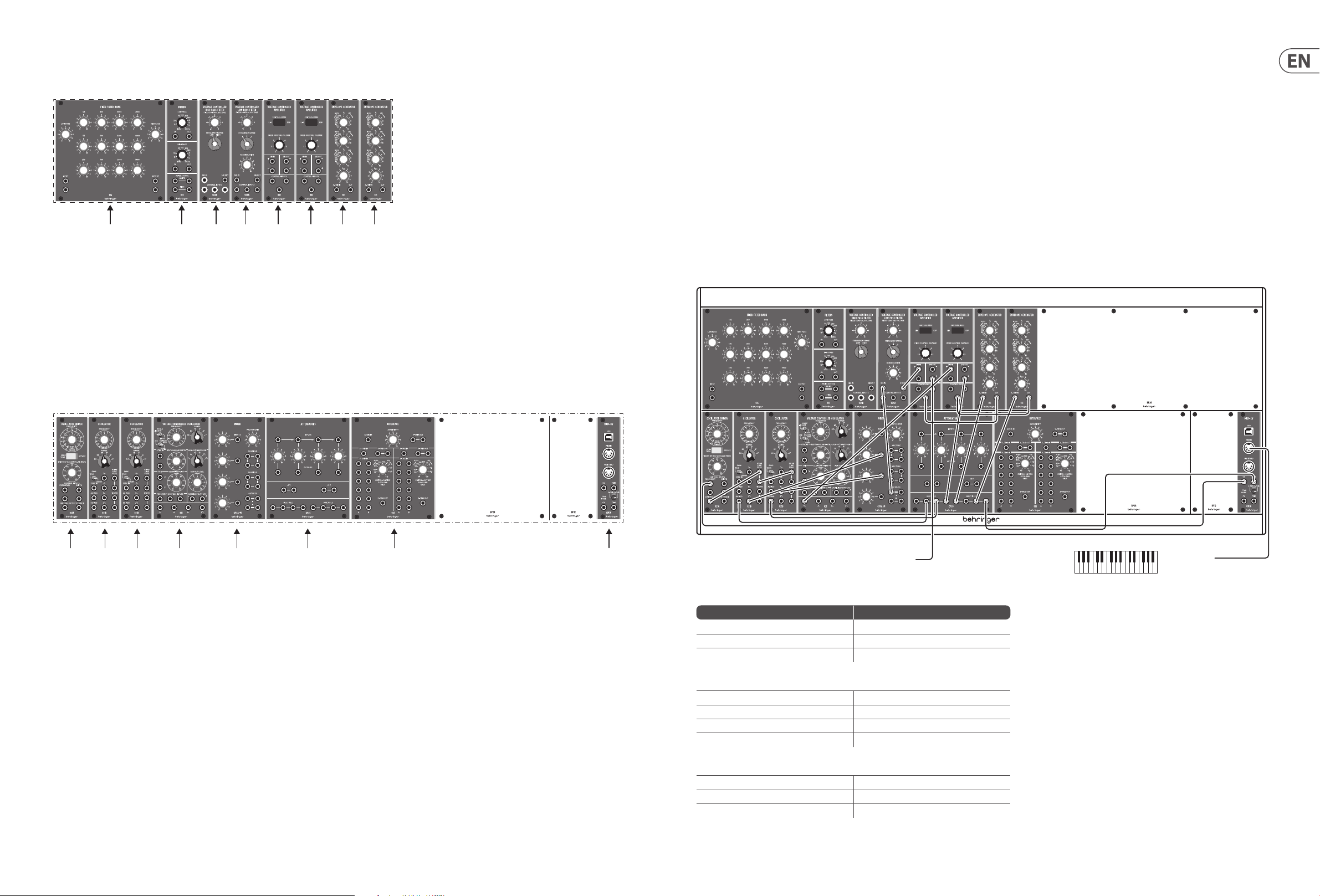
Modules
Your System 15 has two rows of modules
Top Row
(1) 914 Fixed Filter Bank (FFB).
(2) 923 Filters and Noise Sources.
(3) 904B High Pass Filter (HPF
(4) 904A Low Pass Filter (LPF).
(5) & (6) 902 Voltage Controlled Ampliers (VCA).
(6) & (8) 911 Envelope Generators (EG).
System 15 - Getting Started
CONNECTION
To connect the System 15 to your system, please consult the connection guides in specic patches.
HARDWARE SETUP
Make all the connections in your system. Keep the System 15 power turned o when making any connections.
Ensure your sound system is turned down.
Turn on the System 15 before turning on any power ampliers and turn it o last. This will help prevent any turn on or turn o “pops or thumps” in your speakers.
WARM UP TIME
We recommend leaving 30 minutes or more time for the System 15 to warm up before recording or live performance. (Longer if it has been brought in from the cold.)
This will allow the precision circuits time to reach their normal operating temperature and tuned performance.
System 15 Patches
Expressive Lead 1
Bottom Row
(1) 921A Oscillator Driver.
(2) & (3) 921B Voltage Controlled Oscillators (VCO).
(4) 921 Voltage Controlled Oscillator (VCO/LFO).
(5) CP3A – M
(6) CP35 Attenuator / Voltage Source / Multiple.
(7) 961 Interface.
(8) CM1A – MIDI interface.
Further information on all modules can be found on their individual Quick Start Guides at www.behringer.com/downloads.html
MIDI OutTo mixer/amplier/DAW
Voltage Control (pitch)
Source Destination
External MIDI Keyboard – MIDI Out CM1A MIDI Interface MIDI In
CM1A CV Output 921A Frequency Input
921A Frequency Output 921B Frequency Link (in series)
Audio
921B Waveform outs (three of four) CP3A-M Inputs
CP3A-M Output 904A Signal Input
904A Signal O utput 902 Signal Input
902 Signal Output Your mixer/amplier/DAW
Voltage Control (amplitude)
CM1A s-trigger Output Multiple
Multiple Output (two of ) 2 x 911 s-trigger Input
1st 911 Output 1st 902 Control Input
Page 4

6 SYSTEM 15 Quick Start Guide 7
Voltage Control (modulation)
921 Aux Sine Output 2nd 902 Signal Input
2nd 902 Signal Output 921B DC Mod Inputs via Multiple
2nd 911 Output 2nd 902 Control Input
This patch allows a delayed vibrato eect to fade in when a note is held.
The external keyboard controls the pitch and triggering of notes via the CM1A MIDI Interface. As this can be switched between v-trigger and s-trigger then s-trigger
should be selected and the 961 Interface need not be used.
Pitch CV is fed to one of the 921As, which daisy chain to the 921B VCOs. The selected waveform from each oscillator is fed to the CP3A-M mixer; which then feeds the
904A LPF. S-triggers are fed to a multiple, and then to the 911s’ s-trigger inputs
The output of the 904A LPF is fed to one of the 902 VCAs, which feeds out to your mixer, amplier or DAW. This VCA is controlled by the rst 911 EG. The second 911 EG
controls the second 902 VCA.
The second 902 VCA signal input is fed from the 921 LFO. Its output is fed to one of the CP35 multiples, whose outputs feed the DC Modulation inputs of the 921B VCOs
The second 911 should have a long attack time and full sustain.
So long as the rst 911 has a long sustain time, when a note is held a vibrato eect will fade in slowly. When notes are played legato there is little or no vibrato
Space Rock
The pink noise feeding the 904B produces a swept wind eec t, that can be altered with the Fixed Control Voltage
Altering the Fixed Control Voltage of the 904A also produces interesting eects
The CP3A-M balances the two signals, as an alternative feed the outputs of the two lters direct to two mixer or amplier channels. Both sounds benet from a lot
of echo!
Expressive Lead #2
To mixer/amplier/DAW
This patch creates two of the classic ‘space rock’ sounds, and allows them to be mixed together.
Source Destination
921 Sine Wave Output 904A Control Input
921A Frequency Output 2 x 921B Frequency Link (in series)
1st 921B Sine Wave Output 904A Control Input
2nd 921B Sine Wave Output 904B Control Input
923 Pink Noise Output 904B Signal Input
904A Signal O utput CP3A-M Input 1
904B Signal O utput CP3A-M Input 2
CP3A-M Output You r mixer, am pli er, DAW
Control settings are very important for this patch.
Regeneration on the 904A must be set to 9 or 10 to force the lter to self-oscillate
The 921A should have Octave selected and the frequency control set to -6
The 921Bs should be set to ‘Lo’ – these oscillators provide the sweep to the lters
The 921 should be set to ‘Sub’ – this is the main modulation for the self-oscillating lter, and manual alteration of the Frequency control helps to produce the
classic sound.
MIDI OutTo mixer/amplier/DAW
This sound uses Pulse Width Modulation to a pair of oscillators, one of which should be slightly detuned to fatten the sound.
Voltage Control (pitch)
Source Destination
External MIDI Keyboard – MIDI Out CM1A MIDI Interface MIDI In
921A Frequency Output 921B Oscillator Frequency Link (in series)
921A Width Output 921B Oscillator Width Link (in series)
Audio
2 x 921B Square Wave Output CP3A-M Inputs 1 & 2
CP3AM Output 904A Signal Input
904A Signal O utput 902 Signal Input
902 Signal Output Your Mixer/Amplier/DAW
Voltage Control (Amplitude)
CM1A s-trigger Output via Multiple 2 x 911 s-trigger Input
1st 911 Output 1st 902 Control Input
Voltage Control (Modulation)
921 sine wave Output 921A Width Input
921A Width Link 2 x 921B Width Link (in series)
2n d 911 904A Control Input
The detuned 921B VCOs give a fat sound, whose timbre changes constantly at the speed of the 921 sine wave – the 921 should be in Sub mode, speed can be adjusted
to suit.
The sound comes from the 904A LPF, whose Fixed Control Voltage and Regeneration can be set to whatever suits your aim, plus modulation from the second 911 EG.
EG settings can be adjusted to suit for the main part of the sound, although medium to high levels on T2 (decay), T3 (release) and E sus(tain) are recommended.
The second EG should have a medium length T1 (attack), medium T2 (decay) and minimal T3 (release) and E sus(tain).
Page 5

8 SYSTEM 15 Quick Start Guide 9
Percussive Lead
MIDI OutTo mixer/amplier/DAW
A simple, two oscillator lead sound with a hard front end and timbral development which is also suitable for melodic sequencing
Voltage Control (pitch)
Source Destination
External MIDI Keyboard – MIDI Out CM1A MIDI Interface MIDI In
CM1A CV Out via Multiple 921A Frequency Input
921A Frequency Output 921B Frequency Link (in series)
Audio
1st 921B Triangle wave Output CP3A-M mixer Input 1
2nd 921B Sawtooth wave Output CP3A-M mixer Input 2
CP3A-M Output 904A Signal Input
904A Signal O utput 902 VCA
902 Signal Output Your Mixer/Amplier/DAW
Voltage Control (Amplitude)
CM1A s-trigger out via Multiple 2 x 911 s-trigger Input
1st 911 Output 902 Control Input
Voltage Control (Modulation)
921 Sine Wave Out 904A Control Input
2nd 911 Output 904A Control Input
This sound uses two 921B VCOs, with dierent waveforms, and sounds best if one is slightly detuned. They both feed the 904A LPF, and their relative levels can be
adjusted with the CP3A-M mixer as required. The 904A’s output is fed to a 902 VCA, whose amplitude is controlled by the 1st 911 EG
To obtain the percussive edge the 911’s settings should be T1 (attack) 2ms, T2 (decay) 200ms, T3 (release) 200ms, E sus(tain) 4 seconds
The 904A is modulated by a slow sine wave from the 921 LFO and by the 2nd 911 EG, which should have settings around T1 (attack) 1 second, T2 (decay) 50ms,
T3 (release) 4 seconds, E sus(tain) 9
Page 6

10 SYSTEM 15 Quick Start Guide 11
Other important information
Important information
1. Register online. Please register your new
Music Tribe equipment right after you purchase it by
visiting musictribe.com. Registering your purchase using
our simple online form helps us to process your repair
claims more quickly and eciently. Also, read the terms
and conditions of our warranty, if applicable.
2. Malfunction. Should your Music Tribe
Authorized Reseller not be located in your vicinity,
you may contact the Music Tribe Authorized Fulller for
your country listed under “Support” at musictribe.com.
Should your country not be listed, please check if your
problem can be dealt with by our “Online Support” which
may also be found under “Support” at musictribe.com.
Alternatively, please submit an online warranty claim at
musictribe.com BEFORE returning the product.
3. Power Connections. Before plugging the
unit into a power socket, please make sure you are using
the correct mains voltage for your particular model.
Faulty fuses must be replaced with fuses of the same type
and rating without exception.
Page 7

We Hear You
 Loading...