

Page 1
User Manual
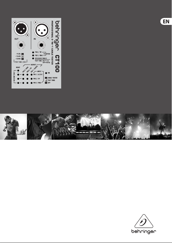
CABLE TESTER CT100
Professional 6-in-1 Cable Tester
Page 2

CABLE TES TER CT100 User Manual
2
1. Introduction
Congratulations! With the CT100, you have purchased an indispensable tool that
enables you to easily check the mos t common cables used by musicians and sound
engineers. Faulty cables are a common cause of f ailure in live and studio situations.
This microprocessor-controlled device was designed to ensure f ast, reliable problem
location. Various test modes and the included belt clip add to its exibility.
2. Cable Tester Mode
◊ Move the ON switc h to the CABLE TESTER position.
Insert one end of your cable into any OUT jack of the CT100. Connect the other end of the
cable to any IN jack . The LEDs will indicate which input pins are connected to each out put
pin. Additionally, the GROUNDED SHIELD LED indicates whether a XLR OUT jack’s shield is
connecte d to the pin 1/sleeve signal.
2.1 How to test intermittent connections
The following method allows you to detect intermittent connections caus ed by wire
breaks or f aulty solder points. While in CABLE TESTER MODE, press RESET to store the
current cable-wiring display and to clear the INTERMIT TENT LEDs. Move the cable
vigorously in all directions and watch the LEDs. Any change in wiring or break in the
signal ow will cause the LED of the cor responding input pin to light up. TheLED will
stay lit until RESET is pressed again, assuring detection of even the shortes t breaks in the
signal ow. It is a good idea to repeat the test after resetting the LEDs to double-che ck
the initial results.
3. Installed Cable Tester Mode
This mode enables you to test cables in xed installations or situations that don’t allow
you to connec t both ends of the cable to the C T100.
◊ Hold down the RESET button w hile moving the ON switc h to the CABLE TESTER
position. The ON LED will blink to indicate that th e CT100 is in INSTALLED CABLE
TESTER MODE.
Page 3

CABLE TES TER CT100 User Manual
3
To test a cable for sho rt circuits, connect one end of the c able to the appropriate
OUT jack of the C T100. The display work s as in CABLE TESTER MODE (see chapter 2).
However, it now indicates connections between out pins. If no LEDs light, the cable is free
of short circuits.
3.1 Continuity check in Installed Cable Tester Mode
For a continuit y check, connect a shorting jack (a jack in which pins are short-circuited
to one another) to the other end of the cable. If there are no break s in the signal ow,
the display will show the corresponding pins as being sho rted to each other. If the display
indicates no short circuit, there is a break in the signal ow.
◊ The testing of intermittent connections works e xactly as in CABLE TESTER MODE
(see chapter 2.1).
◊ INSTALLED CABLE TESTER MODE will n ot indicate connec tions between out and
in pins. Thi s is done in CABLE TESTER MODE (see ch apter 2).
4. Test Tone Mode
◊ Move the ON switc h to the position TEST TONE.
◊ Do not use the TE ST TONE MODE for MIDI cables!
TEST TONE MODE may be used to check signal ow and to facilit ate level adjustments.
It routes a tes t tone to the “+ pin” (pin 2/tip) of all OUT jacks. Use the TEST TONE LEVEL
switch to cho ose between +4 dBu, -10 dBV, or -50 dBV mic level. Please note that this
mode is not intended to work as a voltage standard and that battery voltage will aect
the test tone output level.
4.1 Selection between 1 kHz and 440 Hz
While in TEST TONE MODE, pressing RE SET toggles between 1 kHz and 440 Hz. The TE ST
TONE LED indicates the selected frequenc y: On = 1 kHz, O = 440 Hz.
Page 4

CABLE TES TER CT100 User Manual
4
5. Phantom Power Detect
In TEST TONE MODE, pins 2 and 3 are monitored for exter nal DC voltage
(common ly supplied for condense r micropho nes). The PHANTOM LEDs will light if DC
voltage above approx. 9 V is detected.
6. Wiring
Balanced ¼" TRS connector
strain relief clamp
sleeve
ring
tip
sleeve
ground/shield
ring
cold (-ve)
tip
hot (+ve)
For connection of balanced and unbalanced plugs,
ring and sleeve have to be bridged at the stereo plug.
¼", TT, ⁄" TRS connec tors (mono or TS c onnector s also work)
Unused
Pin 3
Pin 1
(ground)
MIDI conne ctor (2 pins un used)
Unused
Pin 2
Page 5

CABLE TES TER CT100 User Manual
5
12
3
1
2
3
input
1 = ground/shield
2 = hot (+ve)
3 = cold (-ve)
For unbalanced use, pin 1 and pin 3 have to be bridged
output
XLR connectors (pin numbers visible on connectors)
Pin 2 (tip)
Pin 1
(slee ve)
RCA connector
7. Limited Warranty
For the applic able warranty terms and conditions and additional infor mation
regarding MUSIC Gr oup’s Limited Warranty, please see complete details online at
www.music-group.com/warranty.
Page 6

CABLE TES TER CT100 User Manual
6
FEDERAL COMMUNICATIONS COMMISSION
COMPLIANCE INFORMATION
CABLE TESTER CT100
Responsible Party Name: MUSIC Group Services US Inc.
Address: 18912 North Cre ek Parkway,
Phone/Fax No.: Phone: +1 425 672 0816
CABLE TESTER CT100
complie s with the FCC r ules as menti oned in the fo llowingpar agraph:
This equ ipment has be en tested an d found to comp ly with the li mits for a Cla ssB digital d evice, purs uant to part 15 of
the FCC Rul es. These lim its are desi gned to prov ide reasona ble protec tion again st harmful i nterfer ence in a resid ential
instal lation. Thi s equipment g enerates, u ses and can ra diate radio f requenc y energy and, i f not instal led and used
in accord ance with the i nstruc tions, may ca use harmfu l interfer ence to radio c ommunicat ions. Howeve r, there is no
guarant ee that inter ference w ill not occur i n a particu lar install ation. If thi s equipment d oes cause ha rmful inte rference
to radio o r television r eception, w hich can be de termined b y turning the e quipment o and on, the use r is encourag ed to
try to co rrect the i nterfer ence by one or mor e of the follo wingmeasur es:
Suite 20 0 Bothell, WA 98 011,
USA
Fax: +1 425 673 7647
• Reorient or relocate the receiving antenna.
• Increa se the separ ation bet ween the equi pment and rec eiver.
• Connec t the equipm ent into an out let on a circu it dieren t from that to w hich the rece iver is conne cted.
• Consult t he dealer or an e xperienc ed radio/T V technic ian forhelp.
This dev ice complies w ith Part 15 of th e FCC rules. Op eration is s ubject to th e following t wo conditi ons:
(1) this device m ay not cause ha rmful inte rference , and
(2) this dev ice must accep t any interf erence rece ived, inclu ding inter ference tha t may cause und esired ope ration.
Important information:
Change s or modica tions to the eq uipment not e xpressl y approved by MUS IC Group can vo id the user ’s authorit y to use
the equipment.
Page 7

We Hear You
 Loading...