

User Manual
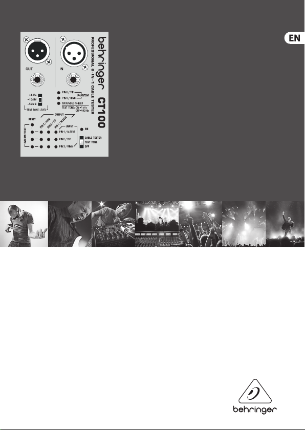
CABLE TESTER CT100
Professional 6-in-1 Cable Tester

2 CABLE TES TER CT100 User Manual
Table of Contents
Important Safety Instructions ................................................................. 3
Legal Disclaimer ........................................................................................ 5
Limited warranty ...................................................................................... 5
1. Introduction .......................................................................................... 6
2. Cable Tester Mode ................................................................................ 6
2.1 How to test intermittent connections ........................................................ 6
3. Installed Cable Tester Mode................................................................ 6
3.1 Continuity check in Installed Cable Tester Mode ................................... 7
4. Test Tone Mode ..................................................................................... 7
4.1 Selection between 1 kHz and 440 Hz ......................................................... 7
5. Phantom Power Detect ........................................................................ 8
6. Wiring .................................................................................................... 8
3 CABLE TES TER CT100 User Manual
Important Safety Instructions
Terminals marked with this
symbol carry electrical current
of sucient magnitude to
constitute risk of electric shock. Use only
high-quality professional speaker cables
with ¼" TS or twist-locking plugs
pre-installed. Allother installation or
modication should be performed only by
qualiedpersonnel.
This symbol, wherever it
appears, alertsyou to the
presence of uninsulated
dangerous voltage inside the
enclosure-voltage that may be sucient
to constitute a risk ofshock.
This symbol, wherever it
appears, alertsyou to
important operating and
maintenance instructions in the
accompanying literature. Please read the
manual.
Caution
To reduce the risk of electric
shock, donot remove the
top cover (or the rear section). No user
serviceable parts inside. Refer servicing to
qualied personnel.
Caution
To reduce the risk of re or
electric shock, do not expose
this appliance to rain and moisture. The
apparatus shall not be exposed to dripping
or splashing liquids and no objects lled
with liquids, suchas vases, shall be placed
on the apparatus.
Caution
These service instructions are
for use by qualied service
personnel only. Toreduce the risk of
electric shock do not perform any servicing
other than that contained in the operation
instructions. Repairs have to be performed
by qualied servicepersonnel.
1. Read these instructions.
2. Keep these instructions.
3. Heed all warnings.
4. Follow all instructions.
5. Do not use this apparatus near water.
6. Clean only with dry cloth.
7. Do not block any ventilation
openings. Install in accordance with the
manufacturer’s instructions.
4 CABLE TES TER CT100 User Manual
8.
Do not install near any heat sources
such as radiators, heat registers, stoves, or
other apparatus (including ampliers) that
produce heat.
9. Do not defeat the safety purpose of
the polarized or grounding-type plug. A
polarized plug has two blades with one
wider than the other. Agrounding-type
plug has two blades and a third grounding
prong. The wide blade or the third prong
are provided for your safety. Ifthe provided
plug does not t into your outlet, consult
an electrician for replacement of the
obsolete outlet.
10. Protect the power cord from being
walked on or pinched particularly at plugs,
convenience receptacles, and the point
where they exit from the apparatus.
11. Use only attachments/accessories
specied by themanufacturer.
12. Use only with the cart,
stand, tripod, bracket,
or table specied by the
manufacturer, orsold with
the apparatus. When a cart is used, use
caution when moving the cart/apparatus
combination to avoid injury from tip-over.
13. Unplug this apparatus during lightning
storms or when unused for long periods
of time.
14. Refer all servicing to qualied service
personnel. Servicing is required when
the apparatus has been damaged in any
way, such as power supply cord or plug
is damaged, liquid has been spilled or
objects have fallen into the apparatus,
the apparatus has been exposed to rain or
moisture, does not operate normally, or
has beendropped.
15. The apparatus shall be connected to
a MAINS socket outlet with a protective
earthing connection.
16. Where the MAINS plug or an appliance
coupler is used as the disconnect device,
the disconnect device shall remain readily
operable.
17. Correct disposal of
this product: This symbol
indicates that this product
must not be disposed of with
household waste, according
to the WEEE Directive (2012/19/EU) and
your national law. This product should be
taken to a collection center licensed for the
recycling of waste electrical and electronic
equipment (EEE). The mishandling of
this type of waste could have a possible
negative impact on the environment
and human health due to potentially
hazardous substances that are generally
associated with EEE. At the same time, your
cooperation in the correct disposal of this
product will contribute to the ecient use

5 CABLE TES TER CT100 User Manual
of natural resources. For more information
about where you can take your waste
equipment for recycling, please contact
your local city oce, or your household
waste collection service.
LEGAL DISCLAIMER
MUSIC Group accepts no liability for
any loss which may be suered by any
person who relies either wholly or in
part upon any description, photograph,
or statement contained herein.
Technical specications, appearances and
other information are subject to change
without notice. All trademarks are the
property of their respective owners. MIDAS,
KLARK TEKNIK, TURBOSOUND, BEHRINGER,
BUGERA and DDA are trademarks or
registered trademarks of MUSIC Group
IP Ltd. © MUSIC Group IP Ltd. 2015 All
rights reserved.
LIMITED WARRANTY
For the applicable warranty terms and
conditions and additional information
regarding MUSIC Group’s Limited
Warranty, please see complete details
online at music-group.com/warranty.

6 CABLE TES TER CT100 User Manual
1. Introduction
Congratulations! With the CT100, you have purchased an indispensable tool that
enables you to easily check the mos t common cables used by musicians and sound
engineers. Faulty cables are a common cause of f ailure in live and studio situations.
This microprocessor-controlled device was designed to ensure f ast, reliable problem
location. Various test modes and the included belt clip add to its exibility.
2. Cable Tester Mode
◊ Move the ON s witch to the CABLE TESTER posi tion.
Insert one end of your cable into any OUT jack of the CT100. Connect the other end of the
cable to any IN jack . The LEDs will indicate which input pins are connected to each output
pin. Additionally, the GROUNDED SHIELD LED indicates whether a XLR OUT jack’s shield is
connecte d to the pin 1/sleeve signal.
2.1 How to test intermittent connections
The following method allows you to detect intermittent connections caus ed by wire
breaks or f aulty solder points. While in CABLE TESTER MODE, press RESET to store the
current cable-wiring display and to clear the INTERMIT TENT LEDs. Move the cable
vigorously in all directions and watch the LEDs. Any change in wiring or break in the
signal ow will cause the LED of the cor responding input pin to light up. TheLED will
stay lit until RESET is pressed again, assuring detection of even the shortes t breaks in the
signal ow. It is a good idea to repeat the test after resetting the LEDs to double-che ck
the initial results.
3. Installed Cable Tester Mode
This mode enables you to test cables in xed installations or situations that don’t allow
you to connec t both ends of the cable to the C T100.
◊ Hold down the RESET but ton while moving the ON s witch to the CABLE TESTER
position. The ON LED will blink to indicate that th e CT100 is in INSTALLED CABLE
TESTER MODE.

7 CABLE TES TER CT100 User Manual
To test a cable for sho rt circuits, connect one end of the c able to the appropriate
OUT jack of the C T100. The display work s as in CABLE TESTER MODE (see chapter 2).
However, it now indicates connections between out pins. If no LEDs light, the cable is free
of short circuits.
3.1 Continuity check in Installed Cable Tester Mode
For a continuit y check, connect a shorting jack (a jack in which pins are short-circuited
to one another) to the other end of the cable. If there are no break s in the signal ow,
the display will show the corresponding pins as being sho rted to each other. If the display
indicates no short circuit, there is a break in the signal ow.
◊ The tes ting of intermittent connections works exactly as in C ABLE TESTER MODE
(see chapter 2.1).
◊ INSTALLED CABLE TESTER MODE will not indic ate connections between out an d
in pins. Thi s is done in CABLE TESTER MODE (see ch apter 2).
4. Test Tone Mode
◊ Move the ON s witch to the position TEST TONE.
◊ Do not use the TEST TONE MODE for MIDI cables!
TEST TONE MODE may be used to check signal ow and to facilit ate level adjustments.
It routes a tes t tone to the “+ pin” (pin 2/tip) of all OUT jacks. Use the TEST TONE LEVEL
switch to cho ose between +4 dBu, -10 dBV, or -50 dBV mic level. Please note that this
mode is not intended to work as a voltage standard and that battery voltage will aect
the test tone output level.
4.1 Selection between 1 kHz and 440 Hz
While in TEST TONE MODE, pressing RE SET toggles between 1 kHz and 440 Hz. The TE ST
TONE LED indicates the selected frequenc y: On = 1 kHz, O = 440 Hz.
8 CABLE TES TER CT100 User Manual
5. Phantom Power Detect
In TEST TONE MODE, pins 2 and 3 are monitored for exter nal DC voltage
(common ly supplied for condense r micropho nes). The PHANTOM LEDs will light if DC
voltage above approx. 9 V is detected.
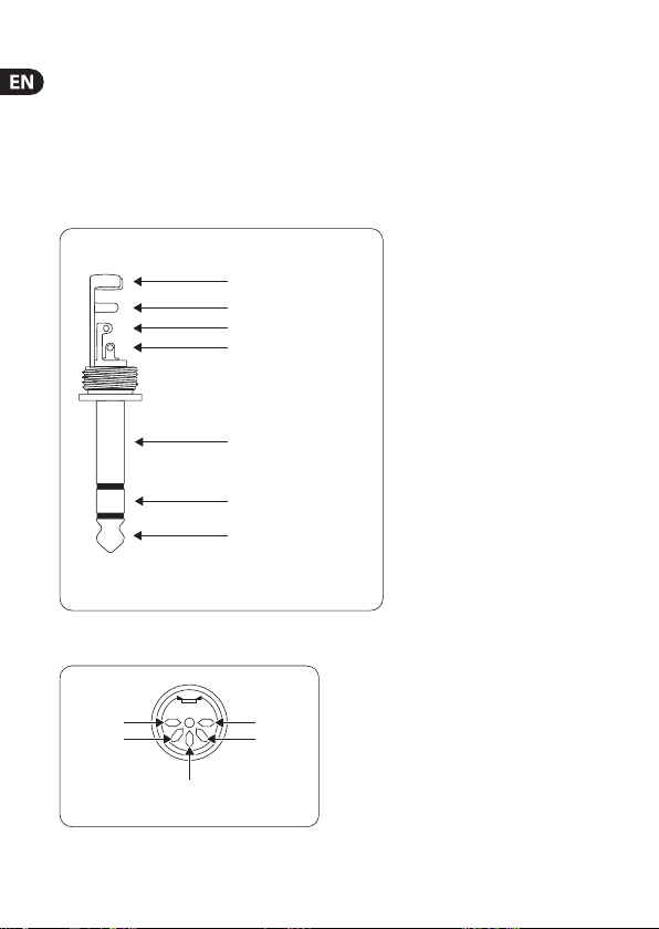
6. Wiring
Balanced ¼" TRS connector
strain relief clamp
sleeve
ring
tip
sleeve
ground/shield
ring
cold (-ve)
tip
hot (+ve)
For connection of balanced and unbalanced plugs,
ring and sleeve have to be bridged at the stereo plug.
¼", TT, ⁄" TRS connec tors (mono or TS c onnector s also work)
Unused
Pin 3
Pin 1
(ground)
MIDI conne ctor (2 pins un used)
Unused
Pin 2

9 CABLE TES TER CT100 User Manual
1
12
3
2
3
input
1 = ground/shield
2 = hot (+ve)
3 = cold (-ve)
For unbalanced use, pin 1 and pin 3 have to be bridged
output
XLR connectors (pin numbers visible on connectors)
Pin 2 (tip)
Pin 1
(slee ve)
RCA connector

10 CABLE TEST ER CT100 User Manual
FEDERAL COMMUNICATIONS COMMISSION
COMPLIANCE INFORMATION
CABLE TESTER CT100
Respon sible Part y Name: MUSIC Grou p Service s NV Inc.
Address: 5270 Procyon Street
Phone Number: +1 702 800 8290
Las Vega s, NV 89118
USA
CABLE TESTER CT100
complies with the FCC rules as mentioned in the followingparagraph:
This equ ipment has bee n tested and fo und to comply wi th the limits f or a ClassB digit al device, pur suant to part
15 of the FCC Rules. Theselimits are designed to provide reasonable protection against harmful interference
in a resid ential insta llation. Thise quipment gen erates, use s and can radiate r adio frequ ency energ y and, if not
instal led and used in a ccordance wit h the instruc tions, may ca use harmful i nterfere nce to radio comm unications .
However, the re is no guarante e that interf erence will no t occur in a par ticular inst allation. Ift his equipmen t does
cause ha rmful inter ference to ra dio or televis ion receptio n, whichcan be de termined by t urning the equ ipment
o and on, th euser is encour aged to try to co rrect the i nterfere nce by one or more of t he followingm easures:
• Reorient or re locate the re ceiving anten na.
• Increase the s eparation be tween the eq uipment and re ceiver.
• Connect the e quipment into a n outlet on a cir cuit diere nt from that to w hich the recei ver is connec ted.
• Consult the deal er or an experi enced radio/ TV techni cian forhelp.
This devi ce complies wi th Part 15 of the FCC r ules. Opera tion is subjec t to the follow ing two condi tions:
(1) this device ma y not cause harm ful interf erence, and
(2) this devi ce must accept an y interfere nce received, i ncludingint erference t hat may cause un desired ope ration.
Important information:
Changes o r modicat ions to the equi pment not exp ressly appro ved by MUSIC Group c an void the user ’s authorit y
to use the equipment.

We Hear You
 Loading...