

Page 1
Quick Start Guide
(Check out behringer.com for Full Manual)
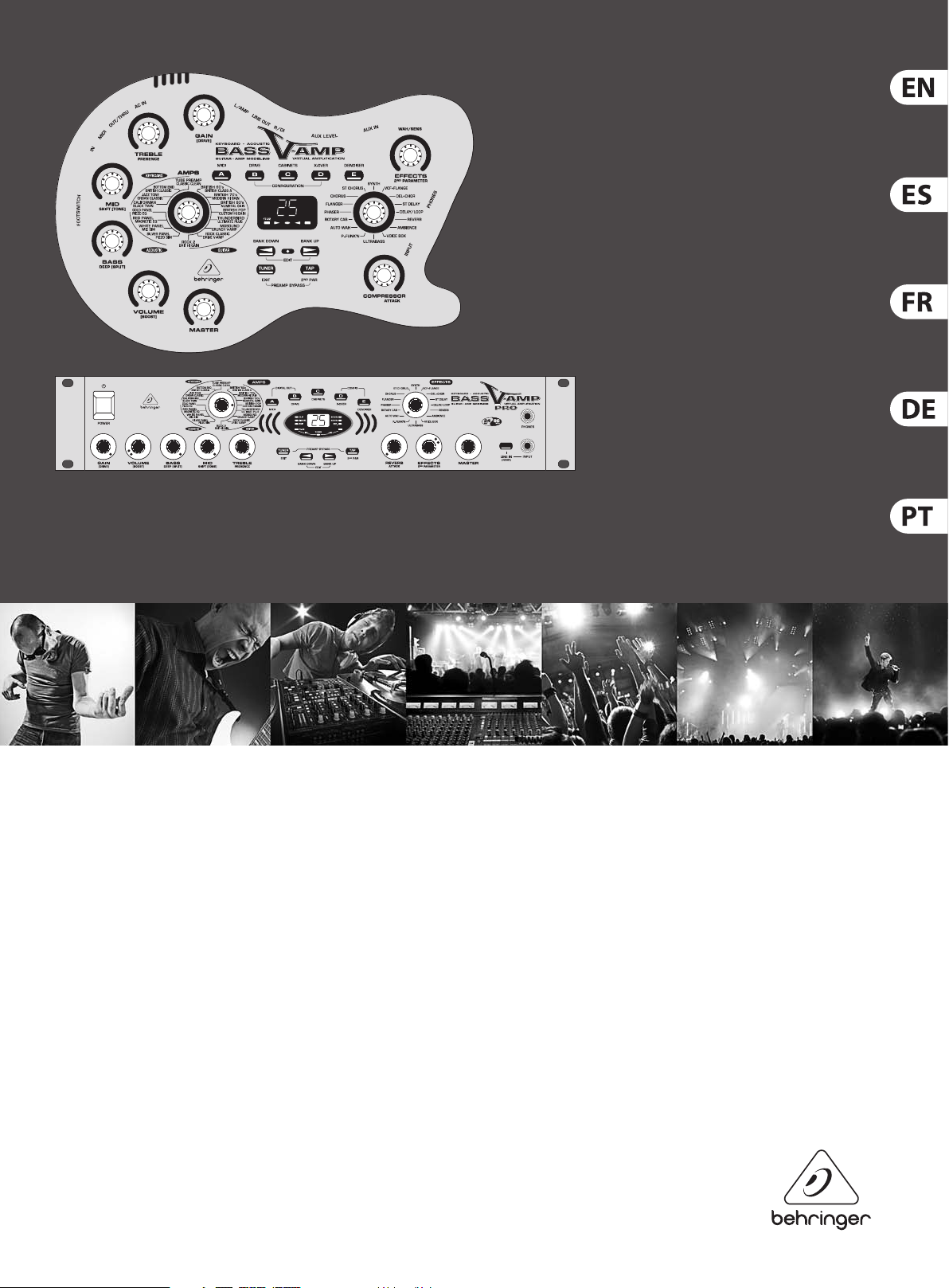
BASS V-AMP LX1B/BASS V-AMP PRO LX1B PRO
The Ultimate Tone Toolbox for Bass/Acoustic/Electric Guitar and
Keyboard Amp Modeling
Page 2
2 BASS V-AMP LX1B/BASS V-AMP PRO LX1B PRO Quick Start Guide 3
9. Do not defeat the safety purpose of the polarized
TO BIND MUSICGROUP BY ANY EXPRESS OR IMPLIED
8. No instale este equipo cerca de fuentes de calor
FOTOCOPIADO O REGISTRO DE CUALQUIER TIPO Y PARA
CUALQUIER FIN, SIN LA AUTORIZACIÓN EXPRESA Y POR
Important Safety
Instructions
Terminals marked with this symbol carry
electrical current of su cient magnitude
to constitute risk of electric shock.
Use only high-quality professional speaker cables with
¼" TS or twist-locking plugs pre-installed. Allother
installation or modi cation should be performed only
by quali edpersonnel.
This symbol, wherever it appears,
alertsyou to the presence of uninsulated
dangerous voltage inside the
enclosure-voltage that may be su cient to constitute a
risk ofshock.
This symbol, wherever it appears,
alertsyou to important operating and
maintenance instructions in the
accompanying literature. Please read the manual.
Caution
To reduce the risk of electric shock, donot
remove the top cover (or the rear section).
No user serviceable parts inside. Refer servicing to
quali ed personnel.
Caution
To reduce the risk of re or electric shock,
do not expose this appliance to rain and
moisture. The apparatus shall not be exposed to dripping
or splashing liquids and no objects lled with liquids,
suchas vases, shall be placed on the apparatus.
Caution
These service instructions are for use
by quali ed service personnel only.
Toreduce the risk of electric shock do not perform any
servicing other than that contained in the operation
instructions. Repairs have to be performed by quali ed
servicepersonnel.
1. Read these instructions.
2. Keep these instructions.
3. Heed all warnings.
4. Follow all instructions.
5. Do not use this apparatus near water.
6. Clean only with dry cloth.
7. Do not block any ventilation openings. Install in
accordance with the manufacturer’s instructions.
8. Do not install near any heat sources such as
radiators, heat registers, stoves, or other apparatus
(including ampli ers) that produce heat.
or grounding-type plug. A polarized plug has two blades
with one wider than the other. A grounding-type plug
has two blades and a third grounding prong. The wide
blade or the third prong are provided for your safety. Ifthe
provided plug does not t into your outlet, consult an
electrician for replacement of the obsolete outlet.
10. Protect the power cord from being walked on or
pinched particularly at plugs, convenience receptacles,
and the point where they exit from the apparatus.
11. Use only attachments/accessories speci ed by
themanufacturer.
12. Use only with the
cart, stand, tripod, bracket,
or table speci ed by the
manufacturer, orsold with
the apparatus. When a cart
is used, use caution when
moving the cart/apparatus
combination to avoid
injury from tip-over.
13. Unplug this apparatus during lightning storms or
when unused for long periods of time.
14. Refer all servicing to quali ed service personnel.
Servicing is required when the apparatus has been
damaged in any way, such as power supply cord or plug
is damaged, liquid has been spilled or objects have fallen
into the apparatus, the apparatus has been exposed
to rain or moisture, does not operate normally, or has
beendropped.
15. The apparatus shall be connected to a MAINS socket
outlet with a protective earthing connection.
16. Where the MAINS plug or an appliance coupler is
used as the disconnect device, the disconnect device shall
remain readily operable.
LEGAL DISCLAIMER
TECHNICAL SPECIFICATIONS AND APPEARANCES
ARE SUBJECT TO CHANGE WITHOUT NOTICE AND
ACCURACY IS NOT GUARANTEED. BEHRINGER,
KLARKTEKNIK, MIDAS, BUGERA, AND TURBOSOUND
ARE PART OF THE MUSIC GROUP MUSICGROUP.COM.
ALL TRADEMARKS ARE THE PROPERTY OF THEIR
RESPECTIVE OWNERS. MUSICGROUP ACCEPTS NO
LIABILITY FOR ANY LOSS WHICH MAY BE SUFFERED
BY ANY PERSON WHO RELIES EITHER WHOLLY OR
IN PART UPON ANY DESCRIPTION, PHOTOGRAPH
OR STATEMENT CONTAINED HEREIN. COLORS AND
SPECIFICATIONS MAY VARY FROM ACTUAL PRODUCT.
MUSIC GROUP PRODUCTS ARE SOLD THROUGH
AUTHORIZED FULLFILLERS AND RESELLERS ONLY.
FULLFILLERSAND RESELLERS ARE NOT AGENTS OF
MUSICGROUP AND HAVE ABSOLUTELY NO AUTHORITY
UNDERTAKING OR REPRESENTATION. THIS MANUAL
IS COPYRIGHTED. NO PART OF THIS MANUAL MAY
BE REPRODUCED OR TRANSMITTED IN ANY FORM
OR BY ANY MEANS, ELECTRONIC OR MECHANICAL,
INCLUDING PHOTOCOPYING AND RECORDING OF ANY
KIND, FOR ANY PURPOSE, WITHOUT THE EXPRESS
WRITTEN PERMISSION OF MUSICGROUPIPLTD.
ALL RIGHTS RESERVED.
© 2013 MUSICGroupIPLtd.
Trident Chambers, Wickhams Cay, P.O. Box 146,
Road Town, Tortola, British Virgin Islands
LIMITED WARRANTY
For the applicable warranty terms and conditions
and additional information regarding MUSIC Group’s
Limited Warranty, please see complete details online at
www.music-group.com/warranty.
Instrucciones de
seguridad
Las terminales marcadas con este símbolo
transportan corriente eléctrica de
magnitud su ciente como para constituir
un riesgo de descarga eléctrica. Utilice solo cables de
altavoz profesionales y de alta calidad con conectores
TS de 6,3 mm o de bayoneta pre jados. Cualquier otra
instalación o modi cación debe ser realizada únicamente
por un técnico cuali cado.
Este símbolo, siempre que aparece,
leadvierte de la presencia de voltaje
peligroso sin aislar dentro de la caja;
estevoltaje puede ser su ciente para constituir un riesgo
dedescarga.
Este símbolo, siempre que aparece,
leadvierte sobre instrucciones operativas
y de mantenimiento que aparecen en la
documentación adjunta. Por favor, lea el manual.
Atención
Para reducir el riesgo de descarga
eléctrica, no quite la tapa (o la parte
posterior). No hay piezas en el interior del equipo que
puedan ser reparadas por el usuario. Si es necesario,
póngase en contacto con personal cuali cado.
Atención
Para reducir el riesgo de incendio o
descarga eléctrica, no exponga este
aparato a la lluvia, humedad o alguna otra fuente que
pueda salpicar o derramar algún líquido sobre el aparato.
Nocoloque ningún tipo de recipiente para líquidos sobre
el aparato.
Atención
Las instrucciones de servicio deben
llevarlas a cabo exclusivamente personal
cuali cado. Para evitar el riesgo de una descarga eléctrica,
no realice reparaciones que no se encuentren descritas
en el manual de operaciones. Lasreparaciones deben ser
realizadas exclusivamente por personalcuali cado.
1. Lea las instrucciones.
2. Conserve estas instrucciones.
3. Preste atención a todas las advertencias.
4. Siga todas las instrucciones.
5. No use este aparato cerca del agua.
6. Limpie este aparato con un paño seco.
7. No bloquee las aberturas de ventilación. Instale el
equipo de acuerdo con las instrucciones del fabricante.
tales como radiadores, acumuladores de calor, estufas u
otros aparatos (incluyendo ampli cadores) que puedan
producir calor.
9. No elimine o deshabilite nunca la conexión a tierra
del aparato o del cable de alimentación de corriente.
Unenchufe polarizado tiene dos polos, uno de los cuales
tiene un contacto más ancho que el otro. Una clavija con
puesta a tierra dispone de tres contactos: dos polos y la
puesta a tierra. El contacto ancho y el tercer contacto,
respectivamente, son los que garantizan una mayor
seguridad. Si el enchufe suministrado con el equipo no
concuerda con la toma de corriente, consulte con un
electricista para cambiar la toma de corriente obsoleta.
10. Coloque el cable de suministro de energía de manera
que no pueda ser pisado y que esté protegido de objetos
a lados. Asegúrese de que el cable de suministro de
energía esté protegido, especialmente en la zona de la
clavija y en el punto donde sale del aparato.
11. Use únicamente los dispositivos o accesorios
especi cados por el fabricante.
12. Use únicamente la
carretilla, plataforma,
trípode, soporte o mesa
especi cados por el
fabricante o suministrados
junto con el equipo.
Altransportar el equipo,
tenga cuidado para evitar
daños y caídas al tropezar con algún obstáculo.
13. Desenchufe el equipo durante tormentas o si no va a
utilizarlo durante un periodo largo.
14. Confíe las reparaciones únicamente a servicios
técnicos cuali cados. La unidad requiere mantenimiento
siempre que haya sufrido algún daño, si el cable de
suministro de energía o el enchufe presentaran daños,
sehubiera derramado un líquido o hubieran caído objetos
dentro del equipo, si el aparato hubiera estado expuesto
a la humedad o la lluvia, si ha dejado de funcionar de
manera normal o si ha sufrido algún golpe o caída.
15. Al conectar la unidad a la toma de corriente eléctrica
asegúrese de que la conexión disponga de una unión
atierra.
16. Si el enchufe o conector de red sirve como único
medio de desconexión, éste debe ser accesiblefácilmente.
NEGACIÓN LEGAL
LAS ESPECIFICACIONES TÉCNICAS Y LA APARIENCIA
EXTERIOR ESTÁN SUJETAS A CAMBIOS SIN
PREVIO AVISO Y NO PODEMOS GARANTIZAR LA
TOTAL EXACTITUD DE TODO LO QUE APARECE
AQUÍ. BEHRINGER, KLARK TEKNIK, MIDAS,
BUGERA, Y TURBOSOUND SON PARTE DEL GRUPO
MUSICGROUP MUSICGROUP.COM. TODAS LAS
MARCAS REGISTRADAS SON PROPIEDAD DE SUS
RESPECTIVOS DUEÑOS. MUSICGROUP NO ACEPTA
NINGÚN TIPO DE RESPONSABILIDAD POR POSIBLES
DAÑOS Y PERJUICIOS SUFRIDOS POR CUALQUIER
PERSONA QUE SE HAYA BASADO COMPLETAMENTE
O EN PARTE EN LAS DESCRIPCIONES, FOTOGRAFÍAS
O EXPLICACIONES QUE APARECEN EN ESTE
DOCUMENTO. LOS COLORES Y ESPECIFICACIONES
TÉCNICAS PUEDEN VARIAR LIGERAMENTE DE UN
PRODUCTO A OTRO. LOSPRODUCTOS MUSICGROUP
SON COMERCIALIZADOS ÚNICAMENTE A TRAVÉS DE
DISTRIBUIDORES OFICIALES. LOS DISTRIBUIDORES
Y MAYORISTAS NO SON AGENTES DE MUSICGROUP,
POR LO QUE NO ESTÁN AUTORIZADOS A CONCEDER
NINGÚN TIPO DE CONTRATO O GARANTÍA QUE
OBLIGUE A MUSICGROUP DE FORMA EXPRESA O
IMPLÍCITA. ESTE MANUAL ESTÁ PROTEGIDO POR LAS
LEYES DEL COPYRIGHT. ESTE MANUAL NO PUEDE
SER REPRODUCIDO O TRANSMITIDO, NI COMPLETO
NI EN PARTE, PORNINGÚN TIPO DE MEDIO, TANTO SI
ES ELECTRÓNICO COMO MECÁNICO, INCLUYENDOEL
ESCRITO DE MUSICGROUPIPLTD.
RESERVADOS TODOS LOS DERECHOS.
© 2013 MUSICGroupIPLtd.
Trident Chambers, Wickhams Cay, P.O. Box 146,
Road Town, Tortola, British Virgin Islands
GARANTÍA LIMITADA
Si quiere conocer los detalles y condiciones aplicables
de la garantía así como información adicional sobre la
Garantía limitada de MUSIC group, consulte online toda la
información en la web www.music-group.com/warranty.
Page 3
4 BASS V-AMP LX1B/BASS V-AMP PRO LX1B PRO Quick Start Guide 5
8. Ne placez pas l’appareil à proximité d’une source
PAS AGENTS DE MUSICGROUP ET N’ONT ABSOLUMENT
Erdungskontakt dient Ihrer Sicherheit. Falls das
gewährten beschränkten Garantie nden Sie online unter
Consignes de sécurité
Les points repérés par ce symbole portent
une tension électrique su sante pour
constituer un risque d’électrocution.
Utilisez uniquement des câbles d’enceintes professionnels
de haute qualité avec ches Jack mono 6,35 mm ou ches
à verrouillages déjà installées. Touteautre installation ou
modi cation doit être e ectuée uniquement par un
personnel quali é.
Ce symbole avertit de la présence d’une
tension dangereuse et non isolée à
l’intérieur de l’appareil - elle peut
provoquer des chocs électriques.
Attention
Ce symbol signale les consignes
d’utilisation et d’entre ! Tien importantes
dans la documentation fournie. Lisez les consignes de
sécurité du manuel d’utilisation de l’appareil.
Attention
Pour éviter tout risque de choc électrique,
ne pas ouvrir le capot de l’appareil ni
démonter le panneau arrière. L’intérieur de l’appareil
ne possède aucun élément réparable par l’utilisateur.
Laissertoute réparation à un professionnel quali é.
Attention
Pour réduire les risques de feu et de choc
électrique, n’exposez pas cet appareil à la
pluie, à la moisissure, aux gouttes ou aux éclaboussures.
Ne posez pas de récipient contenant un liquide sur
l’appareil (un vase par exemple).
Attention
Ces consignes de sécurité et d’entretien
sont destinées à un personnel quali é.
Pouréviter tout risque de choc électrique, n’e ec tuez
aucune réparation sur l’appareil qui ne soit décrite par le
manuel d’utilisation. Les éventuelles réparations doivent
être e ectuées uniquement par un technicien spécialisé.
1. Lisez ces consignes.
2. Conservez ces consignes.
3. Respectez tous les avertissements.
4. Respectez toutes les consignes d’utilisation.
5. N’utilisez jamais l’appareil à proximité d’un liquide.
6. Nettoyez l’appareil avec un chi on sec.
7. Veillez à ne pas empêcher la bonne ventilation
de l’appareil via ses ouïes de ventilation. Respectezles
consignes du fabricant concernant l’installation
del’appareil.
de chaleur telle qu’un chau age, une cuisinière ou tout
appareil dégageant de la chaleur (y compris un ampli
depuissance).
9. Ne supprimez jamais la sécurité des prises bipolaires
ou des prises terre. Les prises bipolaires possèdent deux
contacts de largeur di érente. Leplus large est le contact
de sécurité. Les prises terre possèdent deux contacts plus
une mise à la terre servant de sécurité. Si la prise du bloc
d’alimentation ou du cordon d’ali-mentation fourni ne
correspond pas à celles de votre installation électrique,
faites appel à un électricien pour e ectuer le changement
de prise.
10. Installez le cordon d’alimentation de telle façon
que personne ne puisse marcher dessus et qu’il soit
protégé d’arêtes coupantes. Assurez-vous que le cordon
d’alimentation est sufsamment protégé, notamment au
niveau de sa prise électrique et de l’endroit où il est relié à
l’appareil; cela est également valable pour une éventuelle
rallonge électrique.
11. Utilisez exclusivement des accessoires et des
appareils supplémentaires recommandés par lefabricant.
12. Utilisez
exclusivement des
chariots, des diables,
desprésentoirs, despieds
et des surfaces de
travail recommandés
par le fabricant ou
livrés avec le produit.
Déplacezprécautionneusement tout chariot ou diable
chargé pour éviter d’éventuelles blessures en cas dechute.
13. Débranchez l’appareil de la tension secteur en cas
d’orage ou si l’appareil reste inutilisé pendant une longue
période de temps.
14. Les travaux d’entretien de l’appareil doivent
être e ectués uniquement par du personnel qualié.
Aucunentretien n’est nécessaire sauf si l’appareil est
endommagé de quelque façon que ce soit (dommagessur
le cordon d’alimentation ou la prise par exemple), siun
liquide ou un objet a pénétré à l’intérieur du châssis, si
l’appareil a été exposé à la pluie ou à l’humidité, s’il ne
fonctionne pas correctement ou à la suite d’une chute.
15. L’appareil doit être connecté à une prise secteur
dotée d’une protection par mise à la terre.
16. La prise électrique ou la prise
IEC de tout appareil dénué de
bouton marche/arrêt doit rester
accessible enpermanence.
DÉNI LÉGAL
CARACTÉRISTIQUES TECHNIQUES ET APPARENCE
SUJETTES À MODIFICATIONS SANS PRÉAVIS.
PRÉCISION NON GARANTIE. BEHRINGER, KLARK
TEKNIK, MIDAS, BUGERA, ET TURBOSOUND FONT
PARTIE DU MUSIC GROUP MUSICGROUP.COM.
TOUTES LES MARQUES DÉPOSÉES SONT LA PROPRIÉTÉ
DE LEURS PROPRIÉTAIRES RESPECTIFS. LA SOCIÉTÉ
MUSICGROUP N’ACCEPTE AUCUNE RESPONSABILITÉ
DANS LES ÉVENTUELS DOMMAGES OU PERTES SUBIS
PAR UN TIERS EN SE BASANT EN ENTIER OU EN
PARTIE SUR LES DESCRIPTIONS, PHOTOGRAPHIES OU
DÉCLARATIONS CONTENUES DANS CE DOCUMENT.
LESCOULEURS ET CARACTÉRISTIQUES PEUVENT
VARIER LÉGÈREMENT DE CELLES DU PRODUIT.
LESPRODUITS MUSICGROUP NE SONT VENDUS
QUE PAR LE BIAIS DE REVENDEURS AGRÉÉS.
LESDISTRIBUTEURS ET LES REVENDEURS NE SONT
AUCUNE AUTORITÉ POUR ENGAGER OU REPRÉSENTER
LA SOCIÉTÉ MUSICGROUP DE FAÇON IMPLICITE,
EXPLICITE OU INDIRECTE. CE MODE D’EMPLOI EST
PROTÉGÉ PAR DROITS D’AUTEURS. IL EST INTERDIT
DE TRANSMETTRE OU DE COPIER CE MODE D’EMPLOI
SOUS QUELLE FORME QUE CE SOIT, PAR QUEL MOYEN
QUE CE SOIT, ÉLECTRONIQUE OU MÉCANIQUE,
CEQUI COMPREND LES MOYENS DE PHOTOCOPIE ET
D’ENREGISTREMENT DE QUELLE FAÇON QUE CE SOIT,
QUEL QUE SOIT LE BUT, SANS LA PERMISSION ÉCRITE
EXPRESSE DE MUSICGROUPIPLTD.
TOUS DROITS RÉSERVÉS.
© 2013 MUSICGroupIPLtd.
Trident Chambers, Wickhams Cay, P.O. Box 146,
Road Town, Tortola, Iles Vierges Britanniques
GARANTIE LIMITÉE
Pour connaître les termes et conditions de
garantie applicables, ainsi que les informations
supplémentaires et détaillées sur la Garantie
Limitée de MUSIC Group, consultez le site Internet
www.music-group.com/warranty.
Wichtige
Sicherhteitshinweise
Vorsicht
Die mit dem Symbol markierten
Anschlüsse führen so viel Spannung,
dassdie Gefahr eines Stromschlags besteht.
Verwenden Sie nur hochwertige, professionelle
Lautsprecherkabel mit vorinstallierten 6,35 mm
MONO-Klinkensteckern oder Lautsprecherstecker
mit Drehverriegelung. Alle anderen Installationen
oder Modi kationen sollten nur von quali ziertem
Fachpersonal ausgeführt werden.
Achtung
Um eine Gefährdung durch Stromschlag
auszuschließen, darf die Geräteabdeckung
bzw. Geräterückwand nicht abgenommen werden.
ImInnern des Geräts be nden sich keine vom Benutzer
reparierbaren Teile. Reparaturarbeiten dürfen nur von
quali ziertem Personal ausgeführt werden.
Achtung
Um eine Gefährdung durch Feuer bzw.
Stromschlag auszuschließen, darf dieses
Gerät weder Regen oder Feuchtigkeit ausgesetzt werden
noch sollten Spritzwasser oder tropfende Flüssigkeiten
in das Gerät gelangen können. Stellen Sie keine mit
Flüssigkeit gefüllten Gegenstände, wie z. B. Vasen,
aufdasGerät.
Achtung
Die Service-Hinweise sind nur durch
quali ziertes Personal zu befolgen.
Umeine Gefährdung durch Stromschlag zu vermeiden,
führen Sie bitte keinerlei Reparaturen an dem Gerät
durch, die nicht in der Bedienungsanleitung beschrieben
sind. Reparaturen sind nur von quali ziertem
Fachpersonaldurchzuführen.
1. Lesen Sie diese Hinweise.
2. Bewahren Sie diese Hinweise auf.
3. Beachten Sie alle Warnhinweise.
4. Befolgen Sie alle Bedienungshinweise.
5. Betreiben Sie das Gerät nicht in der Nähe vonWasser.
6. Reinigen Sie das Gerät mit einem trockenen Tuch.
7. Blockieren Sie nicht die Belüftungsschlitze. Beachten
Sie beim Einbau des Gerätes die Herstellerhinweise.
8. Stellen Sie das Gerät nicht in der Nähe von
Wärmequellen auf. Solche Wärmequellen sind z. B.
Heizkörper, Herde oder andere Wärme erzeugende Geräte
(auch Verstärker).
9. Entfernen Sie in keinem Fall die
Sicherheitsvorrichtung von Zweipol- oder geerdeten
Steckern. Ein Zweipolstecker hat zwei unterschiedlich
breite Steckkontakte. Ein geerdeter Stecker hat zwei
Steckkontakte und einen dritten Erdungskontakt.
Derbreitere Steckkontakt oder der zusätzliche
mitgelieferte Steckerformat nicht zu Ihrer Steckdose
passt, wenden Sie sich bitte an einen Elektriker, damit die
Steckdose entsprechend ausgetauscht wird.
10. Verlegen Sie das Netzkabel so, dass es vor
Tritten und scharfen Kanten geschützt ist und nicht
beschädigt werden kann. Achten Sie bitte insbesondere
im Bereich der Stecker, Verlängerungskabel und an
der Stelle, an der das Netzkabel das Gerät verlässt,
aufausreichendenSchutz.
11. Das Gerät muss jederzeit mit intaktem Schutzleiter
an das Stromnetz angeschlossen sein.
12. Sollte der Hauptnetzstecker oder eine
Gerätesteckdose die Funktionseinheit zum Abschalten
sein, muss diese immer zugänglich sein.
13. Verwenden Sie nur Zusatzgeräte/Zubehörteile,
dielaut Hersteller geeignet sind.
14. Verwenden
Sie nur Wagen,
Standvorrichtungen,
Stative, Halter oder Tische,
die vom Hersteller benannt
oder im Lieferumfang
des Geräts enthalten
sind. Falls Sie einen
Wagen benutzen, seien Sie vorsichtig beim Bewegen
der Wagen- Gerätkombination, umVerletzungen durch
Stolpern zuvermeiden.
15. Ziehen Sie den Netzstecker bei Gewitter oder wenn
Sie das Gerät längere Zeit nicht benutzen.
16. Lassen Sie alle Wartungsarbeiten nur von
quali ziertem Service-Personal ausführen. EineWartung
ist notwendig, wenn das Gerät in irgendeiner Weise
beschädigt wurde (z. B. Beschädigung des Netzkabels oder
Steckers), Gegenstände oder Flüssigkeit in das Geräteinnere
gelangt sind, das Gerät Regen oder Feuchtigkeit ausgesetzt
wurde, das Gerät nicht ordnungsgemäß funktioniert oder
auf den Boden gefallen ist.
17. Korrekte Entsorgung
dieses Produkts: Dieses Symbol
weist darauf hin, das Produkt
entsprechend der WEEE
Direktive (2002/96/EC) und der
jeweiligen nationalen Gesetze
nicht zusammen mit Ihren
Haushaltsabfällen zu entsorgen. DiesesProdukt sollte
bei einer autorisierten Sammelstelle für Recycling
elektrischer und elektronischer Geräte (EEE) abgegeben
werden. Wegen bedenklicher Substanzen, diegenerell
mit elektrischen und elektronischen Geräten in
Verbindung stehen, könnte eine unsachgemäße
Behandlung dieser Abfallart eine negative Auswirkung
auf Umwelt und Gesundheit haben. Gleichzeitig
gewährleistet Ihr Beitrag zur richtigen Entsorgung dieses
Produkts die e ektive Nutzung natürlicher Ressourcen.
Fürweitere Informationen zur Entsorgung Ihrer Geräte
bei einer Recycling-Stelle nehmen Sie bitte Kontakt zum
zuständigen städtischen Büro, Entsorgungsamt oder zu
Ihrem Haushaltsabfallentsorgerauf.
HAFTUNGSAUSSCHLUSS
TECHNISCHE DATEN UND ERSCHEINUNGSBILD
KÖNNEN UNANGEKÜNDIGT GEÄNDERT WERDEN.
IRRTÜMER BLEIBEN VORBEHALTEN. BEHRINGER,
KLARK TEKNIK, MIDAS, BUGERA UND TURBOSOUND
SIND TEIL DER MUSIC GROUP MUSICGROUP.COM.
ALLEWARENZEICHEN SIND DAS EIGENTUM IHRER
JEWEILIGEN BESITZER. MUSICGROUP ÜBERNIMMT
KEINE HAFTUNG FÜR VERLUSTE, DIE PERSONEN
ENTSTEHEN, DIE SICH GANZ ODER TEILWEISE AUF
HIER ENTHALTENE BESCHREIBUNGEN, FOTOS ODER
AUSSAGEN VERLASSEN. ABGEBILDETE FARBEN UND
SPEZIFIKATIONEN KÖNNEN GERINGFÜGIG VOM
PRODUKT ABWEICHEN. MUSICGROUP PRODUKTE
WERDEN NUR ÜBER AUTORISIERTE FACHHÄNDLER
VERKAUFT. DIE VERTRIEBSPARTNER UND HÄNDLER
SIND KEINE VERTRETER VON MUSICGROUP UND
SIND NICHT BERECHTIGT, MUSICGROUP DURCH
AUSDRÜCKLICHE ODER STILLSCHWEIGENDE
HANDLUNGEN ODER REPRÄSENTANZEN ZU
VERPFLICHTEN. DIESE BEDIENUNGSANLEITUNG IST
URHEBERRECHTLICH GESCHÜTZT. KEIN TEIL DIESES
HANDBUCHS DARF IN IRGENDEINER FORM ODER
MIT IRGENDWELCHEN MITTELN ELEKTRONISCH
ODER MECHANISCH, INKLUSIVE FOTOKOPIE ODER
AUFNAHME, ZU IRGENDEINEM ZWECK OHNE
DIE SCHRIFTLICHE ZUSTIMMUNG DER FIRMA
MUSICGROUPIPLTD. VERVIELFÄLTIGT ODER
ÜBERTRAGEN WERDEN.
ALLE RECHTE VORBEHALTEN.
© 2013 MUSICGroupIPLtd.
Trident Chambers, Wickhams Cay, P.O. Box 146,
Road Town, Tortola, British Virgin Islands
BESCHRÄNKTE GARANTIE
Die geltenden Garantiebedingungen und zusätzliche
Informationen bezüglich der von MUSIC Group
www. music-group.com/warranty.
Page 4
6 BASS V-AMP LX1B/BASS V-AMP PRO LX1B PRO Quick Start Guide 7
de duas palhetas e um terceiro dente de ligação à terra.
ACREDITA TANTO COMPLETA QUANTO PARCIALMENTE
Instruções de Segurança
Importantes
Aviso!
Terminais marcados com o símbolo
carregam corrente elétrica de magnitude
su ciente para constituir um risco de choque elétrico.
Use apenas cabos de alto-falantes de alta qualidade
com plugues TS de ¼" ou plugues com trava de torção
pré-instalados. Todas as outras instalações e modi cações
devem ser efetuadas por pessoasquali cadas.
Este símbolo, onde quer que o encontre,
alerta-o para a leitura das instruções de
manuseamento que acompanham o
equipamento. Por favor leia o manual de instruções.
Atenção
De forma a diminuir o risco de choque
eléctrico, não remover a cobertura
(ouasecção de trás). Não existem peças substituíveis por
parte do utilizador no seu interior. Para esse efeito recorrer
a um técnico quali cado.
Atenção
Para reduzir o risco de incêndios ou
choques eléctricos o aparelho não deve ser
exposto à chuva nem à humidade. Além disso, não deve
ser sujeito a salpicos, nem devem ser colocados em cima
do aparelho objectos contendo líquidos, tais como jarras.
Atenção
Estas instruções de operação devem ser
utilizadas, em exclusivo, por técnicos de
assistência quali cados. Para evitar choques eléctricos
não proceda a reparações ou intervenções, que não as
indicadas nas instruções de operação, salvo se possuir as
quali -cações necessárias. Para evitar choques eléctricos
não proceda a reparações ou intervenções, que não as
indicadas nas instruções de operação. Só o deverá fazer se
possuir as quali cações necessárias.
1. Leia estas instruções.
2. Guarde estas instruções.
3. Preste atenção a todos os avisos.
4. Siga todas as instruções.
5. Não utilize este dispositivo perto de água.
6. Limpe apenas com um pano seco.
7. Não obstrua as entradas de ventilação. Instale de
acordo com as instruções do fabricante.
8. Não instale perto de quaisquer fontes de calor tais
como radiadores, bocas de ar quente, fogões de sala
ou outros aparelhos (incluindo ampli cadores) que
produzam calor.
9. Não anule o objectivo de segurança das chas
polarizadas ou do tipo de ligação à terra. Uma cha
polarizada dispõe de duas palhetas sendo uma mais larga
do que a outra. Uma cha do tipo ligação à terra dispõe
A palheta larga ou o terceiro dente são fornecidos para
sua segurança. Se a cha fornecida não encaixar na sua
tomada, consulte um electricista para a substituição da
tomada obsoleta.
10. Proteja o cabo de alimentação de pisadelas ou
apertos, especialmente nas chas, extensões, e no local
de saída da unidade. Certi que-se de que o cabo eléctrico
está protegido. Veri que particularmente nas chas, nos
receptáculos e no ponto em que o cabo sai doaparelho.
11. O aparelho tem de estar sempre conectado à rede
eléctrica com o condutor de protecção intacto.
12. Se utilizar uma cha de rede principal ou uma
tomada de aparelhos para desligar a unidade de
funcionamento, esta deve estar sempre acessível.
13. Utilize apenas ligações/acessórios especi cados
pelofabricante.
14. Utilize apenas com
o carrinho, estrutura,
tripé, suporte, ou mesa
especi cados pelo
fabricante ou vendidos
com o dispositivo.
Quandoutilizar um
carrinho, tenha cuidado ao
mover o conjunto carrinho/dispositivo para evitar danos
provocados pela terpidação.
15. Desligue este dispositivo durante as trovoadas
ou quando não for utilizado durante longos períodos
detempo.
16. Qualquer tipo de reparação deve ser sempre
efectuado por pessoal quali cado. É necessária uma
reparação sempre que a unidade tiver sido de alguma
forma dani cada, como por exemplo: no caso do cabo
de alimentação ou cha se encontrarem dani cados;
naeventualidade de líquido ter sido derramado ou
objectos terem caído para dentro do dispositivo; no caso
da unidade ter estado exposta à chuva ou à humidade;
seesta não funcionar normalmente, ou se tiver caído.
17. Correcta eliminação deste
produto: este símbolo indica que
o produto não deve ser eliminado
juntamente com os resíduos
domésticos, segundo a Directiva
REEE (2002/96/CE) e a legislação
nacional. Este produto deverá
ser levado para um centro de recolha licenciado para a
reciclagem de resíduos de equipamentos eléctricos e
electrónicos (EEE). O tratamento incorrecto deste tipo
de resíduos pode ter um eventual impacto negativo
no ambiente e na saúde humana devido a substâncias
potencialmente perigosas que estão geralmente
associadas aos EEE. Ao mesmo tempo, a sua colaboração
para a eliminação correcta deste produto irá contribuir
para a utilização e ciente dos recursos naturais. Paramais
informação acerca dos locais onde poderá deixar o seu
equipamento usado para reciclagem, é favor contactar
os serviços municipais locais, a entidade de gestão de
resíduos ou os serviços de recolha de resíduosdomésticos.
LEGAL RENUNCIANTE
ESPECIFICAÇÕES TÉCNICAS E APARÊNCIA ESTÃO
SUJEITAS A MUDANÇAS SEM AVISO PRÉVIO E NÃO HÁ
GARANTIA DE PRECISÃO . BEHRINGER, KLARKTEKNIK,
MIDAS, BUGERA, ETURBOSOUND FAZEM PARTE
DO MUSIC GROUP MUSICGROUP.COM. TODAS AS
MARCAS REGISTADAS SÃO PROPRIEDADE DOS SEUS
RESPECTIVOS PROPRIETÁRIOS. MUSICGROUP NÃO SE
RESPONSABILIZA POR QUALQUER PERDA QUE POSSA
TER SIDO SOFRIDA POR QUALQUER PESSOA QUE
EM QUALQUER DESCRIÇÃO, FOTO OU AFIRMAÇÃO
AQUI CONTIDA. CORES E ESPECIFICAÇÕES PODEM
VARIAR UM POUCO DO PRODUTO. OSPRODUTOS
DA MUSICGROUP SÃO VENDIDOS ATRAVÉS
DE DISTRIBUIDORES AUTORIZADOS APENAS.
DISTRIBUIDORES E REVENDEDORES NÃO SÃO
AGENTES DA MUSICGROUP E NÃO TÊM AUTORIDADE
ALGUMA PARA OBRIGAR A MUSICGROUP A
QUALQUER TAREFA OU REPRESENTAÇÃO EXPRESSA
OU IMPLÍCITA. ESTEMANUAL TEM DIREITOS
AUTORAIS. PARTEALGUMA DESTE MANUAL PODE
SER REPRODUZIDA OU TRANSMITIDA DE QUALQUER
FORMA OU MEIO, ELETRÔNICO OU MECÂNICO,
INCLUINDO FOTOCÓPIA E GRAVAÇÃO DE QUALQUER
TIPO, PARA QUALQUER INTENÇÃO, SEM A PERMISSÃO
ESCRITA EXPRESSA DE MUSICGROUPIPLTD.
TODOS DIREITOS RESERVADOS.
© 2013 MUSICGroupIPLtd.
Trident Chambers, Wickhams Cay, P.O. Box 146,
Road Town, Tortola, Ilhas Virgens Britânicas
GARANTIA LIMITADA
Para obter os termos de garantia aplicáveis e condições e
informações adicionais a respeito da garantia limitada do
MUSIC group, favor veri car detalhes na íntegra através
do website www.music-group.com/warranty.
Page 5
8 9BASS V-AMP LX1B/BASS V-AMP PRO LX1B PRO Quick Start Guide
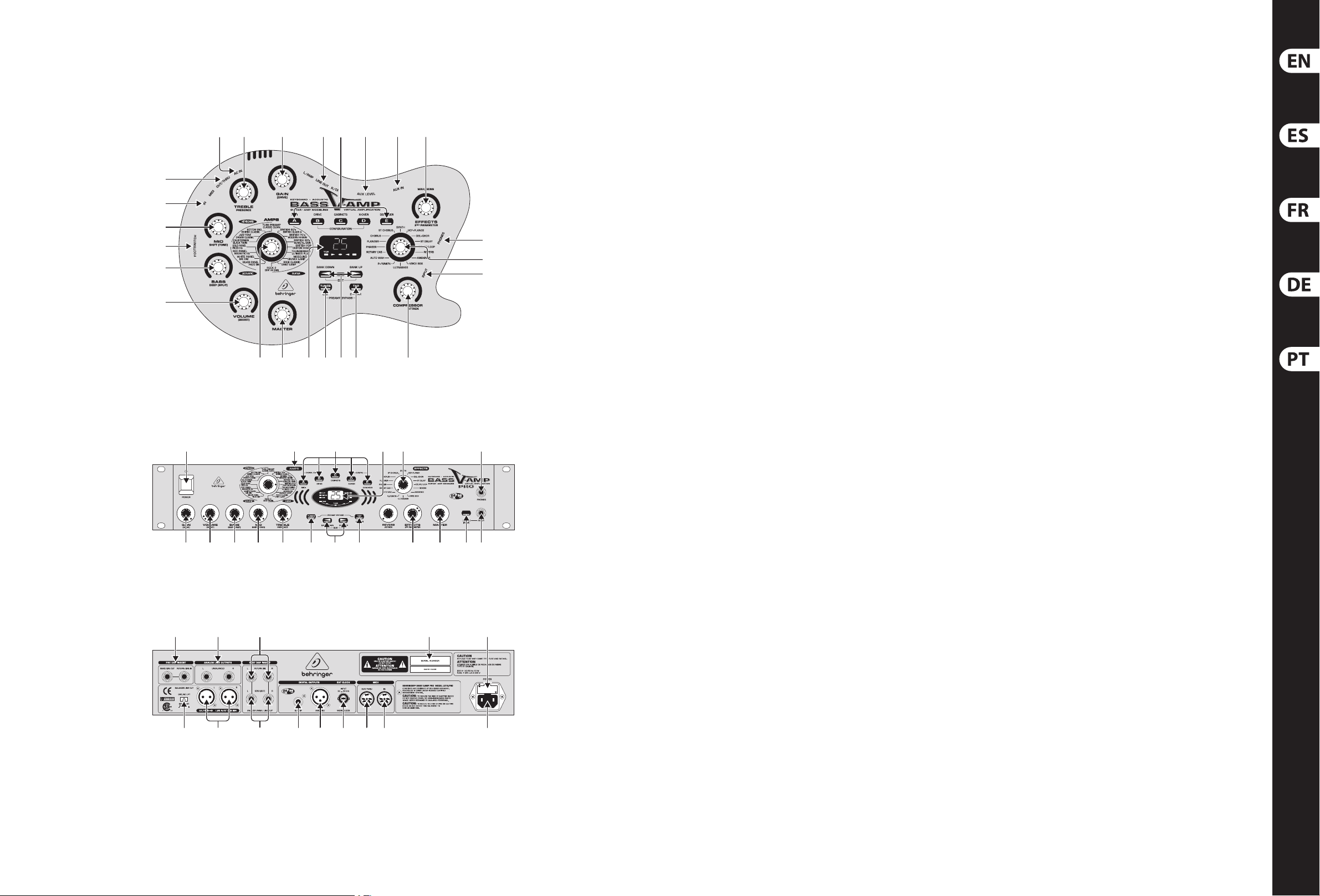
BASS V-AMP LX1B/BASS V-AMP PRO LX1B PRO Controls
(29)
(30)
(5)
(34)
(4)
(3)
(1)
(6)
(7)
(2)
(16)
(7) (8)
(8)
(21)(33)
(9) (11)(12)
(35) (36)
(10)
(12) (13)
(15)
(19)
(13)
(17)
(14)
(19)
(2)
(3) (4) (5) (6)
(20) (21) (22)
(23) (24) (25) (26)
(9) (11)
(10)
(15) (16) (17)(18)
(31) (32)
(33)(27) (28) (29) (30)
Page 6

10 11BASS V-AMP LX1B/BASS V-AMP PRO LX1B PRO Quick Start Guide
BASS V-AMP LX1B/BASS V-AMP PRO LX1B PRO Controls
(EN) Controls
CONTROL ELEMENTS
(1) Turn your BASS V-A MP PRO on using the POWER switch.
The POWER sw itch should always b e in the “O“ posi tion
(depresse d) whenever you rs t connect the uni t to
themains.
(2 ) The GAIN co ntrol determin es level and saturat ion
charac-teristics of the ampsimulation.
(3 ) The VOLUM E control governs t he volume of the
selectedpreset.
(4 ) The BASS c ontrol on the EQ sec tion lowers or ele vates
bass frequencies.
(5 ) The MID con trol lowers or elev ates the mid frequ encies.
(6 ) The TREBLE control regulates the upper frequenc y range
of an acti vatedpreset.
(7 ) The AMPS co ntrol lets you se lect one of the
32amp simulati ons. 16 LEDs surround t his control,
whereby1LED i s assigned to 2 amp ty pes. You select
one of the r st 16 amp types (white l ettering) by simp ly
turning t he control. To selec t the next 16 amps (17 - 32,
grey let tering), keep the TAP butto n pressed as you tur n
the AMPS con trol. Additional ly, you have the option to
activ ate a PREAMP BYPASS via the TU NER (9) and TAP
(11) key combi- nation. When PREAM P BYPASS feature is
activ ated, no AMPS contro l LED is on. To disengage the
PREAMP BYPASS f eature, either sel ect an amp model of
your choic e or press the TUNER and TAP keys a gain.
(8 ) Thes e ve keys are used (among o ther things) for pres et
selec tion of the preset s bank shown in the di splay.
In EDIT mode (ac tivated by simult aneously pressi ng
the arrow ke ys described un der (10)), the func tion of
individ ual keys is indicated b y the print locate d directly
above the re spective but ton:
A: Activa tes the MIDI funct ion. By utilizing t he arrow
keys, the MIDI c hannel used for se nding and receivi ng
(1to 16) can be set up.
After se lecting a MIDI fu nction via the A key,
pressin gtheTAP key relays the MIDI out co nnector to
MIDI Thru. W hen in this mode, the uni t sends no MIDI
informa tion of its own; inst ead, it merely pass es on the
data recei ved at theMIDI In.
B: Switches the DRIVE function on and o. When DRIVE
is enabled , the controls (2), (3) an d (5) take up the
following functions:
• G AIN regulates the di stortion deg ree (“DRIVE”).
• T he VOLUME control regu lates an additiona l
volume cont rol(“BOOST”).
• Us e the MID control like t he tone control on a
simulated d istortion pe dal(“TONE”).
C: This key act ivates the CABINE TS mode. Use the arro w
keys to sele ct a type of loud speaker or a combinat ion
of loudspe akers. You can also comp letely switch o th e
speaker simulation (“-”).
D: Activa tes the X-OVER func tion. Use the arrow s to
regulate t he cut-o freque ncy between h igh-pass and
low-pass lter. This is done in 50grad ients.
E: Activa tes the DENOISER func tion. You may change
the thres hold of the expand er by using the arrow key s.
The EFFECT S control regulate s the sensitivit y of the
noise reduction system, while pressing TAP changes the
funct ion of the EFFECTS con trol so that it regu lates the
frequency range of the noise reduction system.
(9 ) The TUNER key engages the tuner. Additionally, you can
exit the ED IT mode by pressing t his key.
(10) Both arr ow keys are used to sele ct the next pr eset
bank (BANK DOWN und BANK UP). Keepin g the keys
presse d lets you quickly j ump through the pre set banks.
Pressingb oth arrow keys at the s ame time engages th e
EDIT mode. Wh en you press one of the A - E b uttons ((8) )
after wards, each arro w key takes over an edit f unction.
(11) The TAP key has eight functions:
“Ta p”: Tap the TAP key in th e rhythm of a tune,
andthesel ected eec t adjusts automa tically to the
appropriate speed.
“Deep”: By keeping the TAP key pres sed, the BASS
control a ssumes the func tion of a DEEP contro l,
sothat it re gulates the sound in t he deep bass end
ofthespec trum.
“Mid-Shift/Shape”: When an amp simulation is
selec ted using the AMPS con trol, keep the TAP key
presse d and use the MID contro l to regulate the midd le
porti on of the frequenc y range (SHIFT).
“Presence”: Keep the TAP key pressed to u se the
TREBLE cont rol to regulate PRESE NCE in a particul ar
ampsimulation.
“2nd parameter”: The sec ond eect par ameter
(regulated by t he EFFECTS contro l) is accessed by
keepingth e TAP but ton pressed.
“Amp model s 17 - 32”: Keep the TAP key press ed and
selec t the desired simula tion by using the AMPS c ontrol.
“MIDI Thru”: The MIDI Out co nnector can be s et to MIDI
Thru (see (8) A).
“Compressor”: The compressor c ontrol regulate s the
attac k time when the TAP key is kept pre ssed (see (14) ).
(12 ) DISPL AY shows the sele cted eect s bank and gives
information about the changes occurring while editing.
When the tuner is enabled, the display shows the
tuning of the connected instrument. When one of the
amp simulat ions numbered 17 - 32 is selec ted, the LED
located i n the lower left cor ner of the DISPLAY lights u p.
(13 ) The EFFEC TS control let s you select an ee cts preset
or a combina tion of several ee cts. This cont inuously
turnabl e control is surrou nded by a circle of 16 LEDs.
Eachee ct has a corresp onding LED.
(14) The COMPRESSOR control le ts you compress or
limit your s ound. Whenyou turn t he COMPRESSOR
control a s far left as pos sible without tr iggering o
a LED, thedynami c characteris tics of the signal a re
notchange d.
(15) When an ee ct is selecte d using the EFFECTS co ntrol
(13), the propo rtion with whi ch this eect in uences the
entire sound is regulated using theEFFECTS MIX control.
(16) The MASTER cont rol regulates the o verall volume of
your BASS V-AM P/BASSV-AMP PR O.
(17) The connec tor labeled INPUT is th e ¼" TS jack in put
of the BASS V-AM P/BASSV-AMP P RO, which is where
an elec tric bass, an acous tic guitar, akeyboard e tc.
canbeconn ected.
(18) The LINE IN switc h regulates which si gnal source of
the BASS V-AMP PR O is processed. Wh en the switch
is not pres sed, this refer s to the the signal conne cted
to the input c onnector (e.g. elec tric bass). When the
switch is d epressed, the lin e signal connect ed to the
PRE DSP INSERT (LINE I N, (20)) isrouted to th e processor
(particularly useful for keyboards).
(19 ) You can connec t standard head phones to the PHONES
connec tor of your BASS V-AMP/BASS V-AM P PRO.
(20) You can insert e xternal ee cts into the ser ial insert loop
feature d on the BASS V-AMP PRO. The SEND/LINE OUT
connec tor is connected t o the input of your e ects unit
for this pu rpose.
(21 ) The stere o signal of the BASS V-AMP PRO w ithout
analog spe aker simulations can b e taken at the
ANALOGLINEOUTPUT S.
(22 ) The POST DSP INSERT R ETURN (IN) stereo jack pa ir
is used fo r connecting to th e outputs of your e xternal
stereo eects processor.
(23 ) The ground co nnection on the D I OUT outputs (24)
can be inte rrupted with the GROUND LIFT switch.
Thisway, rumbl e noise and ground lo ops can beavoided.
Thegroun d connection is in terrupted when t he switch
isdepres sed (LIFT).
(24) The balanced s tereo signal of your B ASS V-AMP PRO can
be taken at th e DI OUT. This output should b e connected
to two bala nced channel input s on your mixing cons ole.
The signal le vel is set at +4 dBu in st udio modes and at
-10 dBu for live modes .
(25) The connec tion to the inputs o f an external ste reo eects
unit can be m ade using the POST DSP SE ND (OUT)
stereo output.
(26) BASS V-AMP PRO’s signa l can be digitally t aken at the
S/PDIF output.
(27) The digital o utput signal of th e BASS V-AMP PRO
in AES/EBU f ormat is found at the AES/EBU output
(XLRconne ctor), provided AE S/EBU has been sele cted as
output si gnal format (plea se adhere to the seco nd note
under (8) E).
(28) De vices used to ex ternally synch ronize your BASS V-AM P
PRO should be c onnected at th e WORDCLOCK connector.
This is a high -impedance conn ector, meaningthat i t has
no interna l terminal resis tor (75Ohm).
(29 ) This is the MIDI OUT/THRU co nnector of the
BASSV-AMPPRO.
(30) A MIDI foot pe dal, for example the B EHRINGER MIDI
FOOT CONTROL LER FCB1010, can be connected a t the
MIDIINconnec tor.
(31 ) SERIAL NUMBER.
(32 ) FUSE RETAINER/VOLTAGE SELECTOR.
(33 ) Power is supp lied via an IEC connector.
(34) Connec t the stereo jack of yo ur footswitch F S112V
to the FOOTSWITCH connector. This will enable
you to alter nate between di erent presets w ithin a
presetb ank.
(35) The volume of t he signal fed into the AUX I N input is
adjuste d by using the AUX LEVEL control.
(36) By using the AU X IN jack input, you c an feed an
additio nal stereo signal in to your BASS V-AMP.
Amps 1 - 16 (whit e) Amp #
BRITISH '60s 0 68 Marsh all 4 x 12" 6
BRITISH '70 s 1 68 Marsha ll 4 x 12" 6
BRITISH '80s 2 Trace Elliot 4 x 10" 2
BRITISH POP 3 Voc AC100 2 x 15" 9
THUNDERBIRD 4 1 x 8" Tweed 16
MOSOUND 5
ROCK CLASSIC 6 A mpeg SVT 8 x 10" '79 1
ROCK 2 7 Ampeg SV T 8 x 10" '79 1
SILVER PANEL 8
WHITE PANEL 9 6 x 10" SWR G oliath Senio r 3
RED PANEL 10 6 x 10" SWR Golia th Senior 3
GOLD PANEL 11 Ampeg 4 x 10" 4
CALIFORNIAN 12 Mes a/Boogie 2 x 15" 10
JAZZ TONE 13
BOTTOM END 14 Ampeg SV T 18E, 1 x 18" 14
TUBE PREAMP 15 No Cabinet-Simulation —
Amps 17 - 32 (grey) Amp #
BRITISH CLASS A 16 2 x 12" Twin Combo 18
MODERN HI G AIN 17 4 x 12" V-AMP Cust om 23
RECTIFIED HIGH
GAIN
CUSTOM HI GAI N 19 4 x 12" '78 Std . 21
ULTIMATE PLUS 20 4 x 12" V-AMP Cu stom 23
CRUNCH V-AMP 21 4 x 12" '78 Std. 21
DRIVE V-AMP 22 4 x 12" Vi ntage 30 20
BRIT. HIGH GAIN 23 4 x 12" '78 Std. 21
PIEZO SIM. 24 No Cabinet-Simulation —
MIC. SIM. 25 No Cabinet-Simulation —
MAGNETIC EQ 26 No Cabinet-Simulation —
PIEZO EQ 27 No Cabinet-Simulation —
BLACK TWIN 28 2 x 12" Twin Com bo 18
ORGAN CLASSIC 29
BRITISH CLASSIC 30 4 x 12" '78 Std. 21
CLASSIC CLEAN 31 2 x 12" V-AMP C ustom 19
PRE AMP BY PASS 32 No Cabinet-Simulation —
Cabinet simulation
(default setting)
Ampeg B15 1 x 15"
ClosedB ack Combo
Fender B assman 2 x 15"
with JBLs
Polytone A101,
1 x 15" Closed Ba ck Combo
Cabinet simulation
(default setting)
18 4 x 12" Vi ntage 30 20
Leslie 760 Cabinet,
1 x 15" + HF Horn
Assignment of cabinet simulations to amp models
Cab #
Cab #
— BYPASS (NO S PEAKER SIMULATIO N)
1 AMPEG S VT 8 x 10" '97
2 TRACE E LLIOT 4 x 10"
3 SWR GOL IATH 4 x 10"
4 AMPEG 4 x 10"
5 GALLIEN KRUEGER B120
7
11
8
6 68 MAR SHALL 4 x 12"
7 AMPEG B15 1 x 15" CLOSED B ACK COMBO
8 POLYTON E A101 1 x 15" CLOSED BACK COM BO
9 VOX AC100 2 x 15"
10 MESA/B OOGIE 2 x 15"
11 FENDER B ASSMAN 2 x 15" WITH JBLs
12 LESLIE 760 C ABINET, 1 x 15" + HF-DRIVE R
13 SWR 1 x 18"
14 AMPEG SV T 18E, 1 x 18"
15 SUNN COLISEU M 1 x 18" + 1 x 12"
16 1 x 8" TWEED
17 1x 12" MID
18 2 x 12" TWIN COMBO
19 2 x 12" V-AMP CUSTOM
20 4 x 12" VINTAGE 30
21 4 x 12" '78 STD.
22 4 x 12" OFF AXIS
23 4 x 12" V-AMP CUSTOM
Overview of cabinet simulations
Check Out behringer.com for Full Manual
12
Cabinet simulations
Page 7

12 13BASS V-AMP LX1B/BASS V-AMP PRO LX1B PRO Quick Start Guide
BASS V-AMP LX1B/BASS V-AMP PRO LX1B PRO Controles
(ES) Controles
ELEMENTOS DE CONTROL
(1) Con el inter ruptor POWER se encie nde el
BASSV-AMPPRO. E ste interruptor d ebe estar en
laposició n de “apagado” al conec tar el aparato a la
redde corr ienteeléctr ica.
(2 ) Con el co ntrol GAIN determina la amplicación
y/odistorsió n de la simulación del am plicador.
(3 ) El cont rol VOLUME regula el ni vel de la conguraci ón
(preset) elegida.
(4 ) El cont rol BASS de la sección EQ l e permite aumenta r o
atenuar las frecuencias bajas.
(5 ) Con el co ntrol MID puede aumen tar o atenuar
frecuencias medias.
(6 ) Con el co ntrol TREBLE puede aume ntar o atenuar
lasfrecuencias altas.
(7 ) El cont rol AMPS sirve para s eleccionar una de la s
32simulacion es de amplicaci ón. Alrededor de
este cont rol hay 16 LEDs, a cada uno de lo s cuales
le corres ponden respec tivamente dos tip os de
amplic ador. Gire el control AM PS para seleccio nar uno
de las 16 primer as simulaciones (con le tras blancas).
Parasele ccionar las simulac iones de amplica dor 17 - 32
(con letras gr ises), mantenga el pulsa dor TAP presionado
y gire el cont rol AMPS. Además, ti ene usted la
posibili dad de activar un BYPASS d e PREAMPLIFICADO R
con la combin ación de los pulsad ores TUNER (9) y
TAP(11). Si el BYPASS de PREAM PLIFICADOR está a ctivo,
no se ilumin ará ningún LED alred edor del control AM PS.
Para desa ctivar el BYPASS de PRE AMPLIFICADOR,
seleccione cualquier otro modelo de amplicador o pulse
nuevamente la combinación mencionada arriba.
(8 ) Es tos cinco pulsador es sirven para se leccionar una
congura ción (preset) den tro de un banco.
En modo EDIT (ac tivado pulsand o simultáneamente l as
teclas de e cha (10)) la funci ón del pulsador cor responde
a la descr ipción señalada en cima del mismo:
A: activa l a función MIDI. Con ayu da de las teclas
de echa pu ede ajustar el ca nal MIDI (1 a 16) de
entradays alida.
Si usted ha s eleccionado la fu nción MIDI en el modo ED IT
y después p resiona el pulsad or TAP, la sal ida MIDI Out se
conmutar á a MIDI Thru. Es dec ir, que su ap arato no envía
ninguna información MIDI propia, sino que únicamente
transmit e los datos recibid os en la entrada MIDI In.
B: activ a o desactiva la f unción DRIVE. Cuan do la función
DRIVE est á activada, los co ntroles (2), (3) y (5) asumen
las siguientes funciones:
• G AIN regula la cantid ad de distorsión (“ DRIVE”).
• VOLUME regula el volumen adicional (“BOOST”).
• M ID funciona como el co ntrol de tono de un pe dal
de distorsión (“TONE”).
C: este inter ruptor activ a el modo CABINETS. C on las
teclas de e cha puede selec cionar algún tipo de a ltavoz,
una combina ción de altavoces, o d esactivar la si mulación
de altavoz (“-”).
D: selecci ona la función X-OVER . Con las teclas de
echa pue de usted determ inar la frecuenc ia de cruce
entre los l tros pasa altas y p asa bajas del divi sor de
frecu enciasdel efec to.
E: activ a la función DENOISER . Mediante las tecla s de
echa se mo dica el umbral d el expansor. Con el cont rol
EFFECTS se a justa la sensibili dad y con TAP + EFFECTS el
rango de frecuencia del sistema de disminución de ruido.
(9 ) TUNER sir ve para activar e l anador. Al presionar e ste
pulsado r puede también sa lir (“Exit” ) del modo EDIT.
(10) Con las tecla s de echa cambia us ted de banco
(BANKDOWN y BANK UP). Si se mantie ne pulsada
la tecla pue de saltar rápida mente entre los banco s.
Alpulsar si multáneamente las d os echas se act iva
el modo EDIT. Si ento nces se presiona al guno de los
pulsado res A - E ((8)), las te clas de echa asume n una
función de edición.
(11) El pulsa dor TAP desempeña ocho funciones:
“Ta p”: pr esione el pulsado r TAP al ritm o de una canción
y el efec to seleccionado s e ajustará autom áticamente al
tempo velocidad correspondiente.
“Deep”: con el pulsador TAP (11) presio nado, el control
BASS se conv ierte en control D EEP, qu e le permite afec tar
a las frecuencias más graves.
“Mid-Shift/Shape”: si ha seleccionado una simulación
de amplic ador con el contro l AMPS, puede ajust ar
(SHIFT) la f recuencia medi a manteniendo el puls ador
TAPpresionado y g irando el control M ID.
“Presence”: con el pulsador TAP pres ionado y el
controlT REBLE puede modi car el ajuste PRESEN CE de
lasimulación de amplicador seleccionada.
“2nd parameter”: el contr ol EFFECTS sirve p ara
ajustar u n segundo paráme tro de efectos , manteniendo
presionado el pulsador TAP.
“Modelo s de amplicad or 17 - 32”: mantenga
pulsado el pulsador TAP y seleccione la simulación
deseada co n el control AMPS.
“MIDI Thru”: la salida MIDI O ut puede conmuta rse a
MIDI Thru (vea (8) A).
“Compresor”: con el pulsador TAP pres ionado y el
control COM PRESSOR puede ajus tar los tiempos de
ataque y re lajación (vea (14) ).
(12 ) La PANTALLA le muestr a el banco de efect os
selecci onado y le informa so bre las modicac iones
de los pará metros durante la e dición. Al activ ar el
anador, la PANTALLA le mue stra la anación d el
instrumento conectado. Al seleccionar las simulaciones
de amplic ador 17 - 32 se ilumina el LED en la es quina
inferior izquierda de la PANTALLA.
(13 ) El contro l EFFECTS le perm ite seleccionar un a
conguración de efecto o una combinación de efectos.
Alreded or de este control i nnito existen 16 LEDs ,
cadauno de l os cuales está asi gnado a un efecto.
(14) La funci ón COMPRESSOR le permite comprim ir o
limitar un a señal. Si gira el cont rol COMPRESSOR hacia l a
izquierda hasta que no se ilumine ningún LED, no se verá
afect ada la dinámica de la se ñal.
(15) Después d e seleccionar un ef ecto mediante e l control
EFFECTS (13), pued e determinar su pro porción respec to al
sonido or iginal con el contro l EFFECTS MIX .
(16) Con el contro l MASTER se determina el volumen general
del BASS V-AMP/BA SS V-AMP PRO.
(17) Use la entra da INPUT con jack de 6,3 mm del
BASSV-AMP/BASS V-AM P PRO para conect ar su
guitar raeléctric a, acústica, tecl ados, etc.
(18) El pulsado r LINE IN determina qué señal será procesada
por el BASS V-A MP PRO. Si no está pulsad o, la señal
proces ada es aquella pres ente en la entrada de alt a
impedancia INPUT (por ejemplo, una guitarra eléctrica).
Si el pulsad or está presion ado, entonces la señal
proces ada será aquella pre sente en la entrada PR E DSP
INSERT (LINE IN, (20)) (espe cialmente útil pa ra teclados).
(19 ) La entrad a PHONES le per mite escuchar la se ñal
de audio del B ASS V-AMP/BASS V-AMP PRO con
unosauriculares.
(20) El BASS V-AMP PRO dis pone de un punto de inse rción
para util izar efectos e xternos. Par a ello debe conect ar la
salida SEND/LINE OUT co n la entrada del proce sador de
efec tos externo.
(21 ) En las salida s ANALOG LINE OUTPUTS dispone de la
señal est éreo del BASS V-AMP PRO si n simulación de
altavoces analógica.
(22 ) Utilice los jac ks de entrada POST D SP INSERT RETURN
(IN) para con ectar las salida s de un procesado r de
efec tos estéreo ex terno.
(23 ) Al pulsar el p ulsador GROUND LIFT rompe la conexi ón
a tierra en l as salidas DI OUT (24) , evitando así buc les
dezumbido.
(24) En la salida DI OUT d ispone de la señal es téreo
balancead a del BASS V-AMP PRO. Conec te estas salidas
a dos entra das balanceadas de su m esa de mezclas.
Paralos mod os de estudio el ni vel está ajusta do a
+4dBu y para l os modos de direc to a -10 dBu.
(25) Utilice la sali da estéreo POST DSP S END (OUT)
paracone ctar un proces ador de efecto s estéreo ext erno.
(26) Aquí dispone d e la señal del BASS V-AMP PRO en e l
formato d igital S/PDIF.
(27) En estas sa lidas XLR dispone de la s eñal del BASS V-AMP
PRO en el for mato digital AES/EBU, siempre y cuan do
haya selec cionado AES/EBU com o formato de salida .
(28) La entrada WORD CLOCK con conector B NC sirve para
sincroni zar su BASS V-AMP PRO con ap aratos extern os.
Esta en trada es de alta impe dancia, es decir, no disp one
de una resis tencia terminal in terna (75 Ω).
(29 ) La salida MIDI OUT/THRU d el BASS V-AMP PRO está
congura da de fábrica como M IDI Out, pero pued e
conmutarse a MIDI Thru.
(30) En la entrada M IDI IN puede conecta r un pedal
MIDI (como el MIDI F OOT CONTROLLER FCB1010
deBEHRINGER).
(31 ) NÚMERO DE SERIE.
(32 ) PORTAFUSIBLES / SELECCIÓN DE TENSIÓN.
(33 ) La conex ión a la red eléctr ica se realiza me diante el
cable de re d suministrado. É ste cumple con tod as las
disposiciones de seguridad necesarias.
(34) Conecte s u pedal FS112V en la entr ada FOOTSWITCH.
Esto le pe rmite cambiar de co nguración dent ro de un
mismo banco.
(35) Con el contro l AUX LEVEL determ ina el volumen de la
señal alimentada en la entrada AUX IN.
(36) La entrad a AUX IN le permite alim entar al BASS V-AMP
con una seña l estéreo adicio nal, como puede ser una c aja
de ritmo s o un reproducto r.
Amplicadores
1 - 16 (blanco)
BRITISH '60s 0 68 Marsh all 4 x 12" 6
BRITISH '70 s 1 68 Marsha ll 4 x 12" 6
BRITISH '80s 2 Trace Elliot 4 x 10" 2
BRITISH POP 3 Voc AC100 2 x 15" 9
THUNDERBIRD 4 1 x 8" Tweed 16
MOSOUND 5
ROCK CLASSIC 6 A mpeg SVT 8 x 10" '79 1
ROCK 2 7 Ampeg SV T 8 x 10" '79 1
SILVER PANEL 8
WHITE PANEL 9 6 x 10" SWR G oliath Senio r 3
RED PANEL 10 6 x 10" SWR Golia th Senior 3
GOLD PANEL 11 Ampeg 4 x 10" 4
CALIFORNIAN 12 Mes a/Boogie 2 x 15" 10
JAZZ TONE 13
BOTTOM END 14 Ampeg SV T 18E, 1 x 18" 14
TUBE PREAMP 15 No simulación cabinet —
Amplicadores
17 - 32 (grey)
BRITISH CLASS A 16 2 x 12" Twin Combo 18
MODERN HI G AIN 17 4 x 12" V-AMP Cust om 23
RECTIFIED HIGH
GAIN
CUSTOM HI GAI N 19 4 x 12" '78 Std . 21
ULTIMATE PLUS 20 4 x 12" V-AMP Cu stom 23
CRUNCH V-AMP 21 4 x 12" '78 Std. 21
DRIVE V-AMP 22 4 x 12" Vi ntage 30 20
BRIT. HIGH GAIN 23 4 x 12" '78 Std. 21
PIEZO SIM. 24 No simulación cabinet —
MIC. SIM. 25 No simulación cabinet —
MAGNETIC EQ 26 No simulación cabinet —
PIEZO EQ 27 No simulación cabinet —
BLACK TWIN 28 2 x 12" Twin Com bo 18
ORGAN CLASSIC 29
BRITISH CLASSIC 30 4 x 12" '78 Std. 21
CLASSIC CLEAN 31 2 x 12" V-AMP C ustom 19
PRE AMP BY PASS 32 No simulación cabinet —
Simulación cabinet
Amp #
Amp #
18 4 x 12" Vi ntage 30 20
(preajuste)
Ampeg B15 1 x 15"
ClosedB ack Combo
Fender B assman 2 x 15"
with JBLs
Polytone A101,
1 x 15" Closed Ba ck Combo
Simulación cabinet
(preajuste)
Leslie 760 Cabinet,
1 x 15" + HF Horn
Simulaciones de altavoz
Cab #
7
11
8
Cab #
— BYPASS (NO S PEAKER SIMULATIO N)
1 AMPEG S VT 8 x 10" '97
2 TRACE E LLIOT 4 x 10"
3 SWR GOL IATH 4 x 10"
4 AMPEG 4 x 10"
5 GALLIEN KRUEGER B120
6 68 MAR SHALL 4 x 12"
7 AMPEG B15 1 x 15" CLOSED B ACK COMBO
8 POLYTON E A101 1 x 15" CLOSED BACK COM BO
9 VOX AC100 2 x 15"
10 MESA/B OOGIE 2 x 15"
11 FENDER B ASSMAN 2 x 15" WITH JBLs
12 LESLIE 760 C ABINET, 1 x 15" + HF-DRIVE R
13 SWR 1 x 18"
14 AMPEG SV T 18E, 1 x 18"
15 SUNN COLISEU M 1 x 18" + 1 x 12"
16 1 x 8" TWEED
17 1x 12" MID
18 2 x 12" TWIN COMBO
19 2 x 12" V-AMP CUSTOM
20 4 x 12" VINTAGE 30
21 4 x 12" '78 STD.
22 4 x 12" OFF AXIS
23 4 x 12" V-AMP CUSTOM
Cabinet simulations
Asignac ión de altavoces a los m odelos de amplic ador
Si quiere acceder al manual de instrucciones
completo, vaya a la página web behringer.com
12
Page 8

14 15BASS V-AMP LX1B/BASS V-AMP PRO LX1B PRO Quick Start Guide
BASS V-AMP LX1B/BASS V-AMP PRO LX1B PRO Réglages
(FR) Réglages
COMMANDES ET CONNEXIONS
(1) Le commutateur POWER met le BASS V-A MP
PRO sous tens ion. L’appareil d oit être éteint
(commutateu rrelâché) lorsq ue vous le reliez à la
tensionse cteur.
(2 ) La com mande GAIN détermine l’amplication de la
simulation d’ampli.
(3 ) Le potentiomètre VOLUME dé nit le volume de la
presets électionnée.
(4 ) Le bou ton BASS de la sectio n d’égali sation permet
d’augmenter ou de réduire le niveau des graves.
(5 ) L a commande MID sert a u réglage du niveau de smédiums.
(6 ) Le bou ton TREBLE contrôle les f réquences haute s de la
preset active.
(7 ) La mo lette AMPS sert à la s élection de l’un de s 32
modèles d ’ampli. U ne couronne de 16 LED encerc le cette
commande. A c haque LED correspo ndent deux modèl es
d’ampli. Pour s électionner l ’un des 16 pre miers modèles
d’ampli (sérigraphie blanche), tournez simplement la
commande A MPS. Pour sélect ionner l’un des modèl es
d’ampli 17 à 32 (sérigrap hie grise), maintenez la t ouche
TAP enfoncée tou t en tournant le bout on AMPS. Vous
avez égalem ent la possibilité d ’act iver un bypass du
préampli (PREAMP BYPASS) en appuyant simultanément
sur les touc hes TUNER (9) et TAP (11). Lo rsque le
bypass es t actif, aucune LED d e la commande AMPS
n’est allumée. O n désactive le by pass du préampli en
sélec tionnant un modèle d ’ampli ou en rappuyant s ur les
deux touches.
(8 ) Ces ci nq touches serve nt à la sélection d es presets au
sein d’une mêm e banque.
En mode EDIT, que l’on ac tive en appuyant
simultanément sur les touches échées dont les
fonct ions sont décrit es en (10), la fon ction de ces
touchesco rrespond à la sér igraphie qui les sur plombe :
A : Active le s fonctions MID I. A l’aide des touches
échée s, on peut alors sél ectionner le ca nal de réception
et d’émission MI DI entre 1 et 16.
En mode EDIT, aprè s avoir sélectio nné les fonctio ns
MIDI via la tou che A, appuyez sur la to uche TAP pour
transf ormer la sorti e MIDI Out en sorti e MIDI Thru.
Dansce cas, l ’appar eil n’émet pas ses propr es données
MIDI mais cell es qu’il reçoit à l’entr ée MIDI In.
B : Active ou d ésactive la fo nction DRIVE, un e simulation
de pédale s de distorsion. Lo rsque cette fo nction est
active, l es commandes (2) , (3) et (5) contrôlent les
paramètres suivants :
• GAIN déter mine l’intensit é de la distorsio n (« DRIVE »).
• VO LUME est un réglage de vo lume (« BOOST »).
• MID correspond au correcteur de fréquences (« TO NE »).
C : Met le mode C ABINETS en fonc tion. A l’aide des
touches échées, sélec tionnez un typ e de bae ou une
combinais on de diérents b aes. On peut égal ement
désac tiver la simulation d e haut-parleur (acha ge « - »).
D : Sélec tionne la fonct ion X-OVER. Grâce aux to uches
échée s, on peut alors déte rminer, sur 50 pas,
lafréqu ence de transition e ntre le passe-h aut et le
passe-bas du ltre actif des eets.
E : Active la f onction DENOISE R. On dénit le seui l de
son expa nseur à l’aide des touch es échées. On rè gle
la sensibi lité avec le bouton EFFEC TS et la plage de
fréque nces traitée par le s ystème de suppr ession de
bruitavec l a combinaison de tou ches TAP+EFFECTS.
(9 ) La tou che TUNER active l’accord eur. Elle permet
égalemen t de quitter (« Exit ») le mod e d’édit ion EDIT.
(10) On sélec tionne une banqu e à l’aide des touches é chées
(BANK DOWN et BANK UP). Une pressio n prolongée
sur ces touc hes permet de se dé placer rapidement a u
sein des ba nques. En appuyan t simultanément su r les
deux touc hes échées, on ac tive le mode EDIT dan s
lequel ell es servent à l’éditi on de paramètres a près avoir
appuyé sur l ’une des touches A à E ((8)).
(11) La touc he TAP possède huit fonctions :
« Tap » : Tapez sur la touche TAP au r ythme de la
musique po ur régler la vitess e de l’eet sélect ionné.
« Deep » : En mai ntenant la touche TAP enfonc ée,
ontrans forme le bouton BA SS en commande DEEP.
Cettefo nction règle la p art des fréqu ences basses
dansleson.
« Mid-Shift/Shape » : Une fois un modèle d’amp li
sélec tionné via le bouto n AMPS, maintenez la tou che
TAPenfoncée tou t en tournant la comma nde MID pour
régler le s médiums (SHIFT).
« Presen ce » : Maintenez la touche TAP enfoncée tout
en tournan t le bouton TREBLE pou r régler le paramè tre
PRESENCE du m odèle d’ampli sélec tionné.
« 2nd param eter » : On règle le second paramètre
d’eet en main tenant la touche TAP enfonc ée tout en
tournant l e bouton EFFECTS.
« Amps 17 - 32 » : Maintenez la touche TAP enfoncée
et sélec tionnez l’un des mo dèles d’ampli 17 à 32 via le
bouton AMPS.
« MIDI Thru » : Per met de transfo rmer la sortie MID I Out
en sort ie MIDI Thru (voir (8) A).
« Compre ssor » : On détermine les paramètres
temporels (attaque et relâchement) du compresseur en
maintenan t la touche TAP enfoncée tou t en tournant le
bouton Compressor (voir (14)).
(12 ) L’AF FIC HEUR indique la banque sélectionnée ainsi
que les modications de paramètre lors de l’édition.
Si l’accordeur e st actif, l’AFFICHEUR in dique la justesse
de l’instrument. La LED du coin inférieur gauche de
l’AFFICHEUR s’allume lo rsqu’on sélect ionne l’une des
amplis 17 à 32.
(13 ) Le bouton E FFECTS permet de sélectionner un
eet ou un e combinaison d’eet s. Une couronne de
16LED entoure ce tte molette. A ch acune de ces LED
corresp ondun eet.
(14) La fonc tion COMPRESSOR permet de compr esser ou de
limiter le si gnal général. Lors que l’on tourne le bout on
COMPRESSOR ve rs la gauche jusqu ’à ce qu’aucune LED ne
s’allume, la dyna mique du signal n’est pas t raitée.
(15) Après avoir s électionné un e et avec la commande
EFFECTS (13), o n détermine sa pro portion au sein d u son
global via l e bouton EFFECTS MIX.
(16) Le potentiomètre MASTER détermine le volume général
du BASS V-AMP/BASS V-A MP PRO.
(17) Reliez votre instrument (basse électrique, clavier,
guitarea coustique, etc.) à l’entré e INPUT du
BASSV-AMP/BASS V-AM P PRO.
(18) Le commutateur LINE IN dénit la sou rce traitée par le
BASS V-AMP PRO. Lor squ’il est relâ ché, le signal traité
est celui q ui alimente l’entrée hau te-impédance IN PUT
(votre bass e par exemple). Lorsqu’ il est enfoncé, le
signal tra ité par le process eur est celui de l’entré e ligne
PRE DSP INSERT (LINE I N, (20)). Nous reco mmandons aux
claviéristes d’utiliser cette entrée.
(19 ) L’embase PHONES est la sor tie casque du BASS V-A MP/
BASS V-AMP PRO.
(20) Le BASS V-AMP PRO pos sède une boucle d ’eet s
sériellepermettant l’intégration d’eets externes.
Pource fair e, reliez la sorti e SEND/LINE OUT à l’entrée
du proces seurd’eets.
(21 ) Les sort ies ANALOG LINE OUTPUTS délivre nt le
signal sté réo sans simulatio n de haut-parleur du
BASSV-AMPPRO.
(22 ) Reliez la pair e de jacks stéréo P OST DSP INSERT
RETURN (IN) aux sortie s d’un multi-eet s téréo.
Cesentré es servent donc de r etour de la boucle d ’eet s.
(23 ) Le commutateur GROUND LIFT permet d’interrompre
la mise à la mass e des sorties D I OUT (24). Cette f onction
permet d e supprimer les éven tuels ronement s et
boucles d e masse. La mise à la mass e est interromp ue
quand le comm utateur est en pos ition « LIFT ».
(24) La sorti e symétrique DI O UT délivre le signal s téréo du
BASS V-AMP PRO. Ra ccordez-la à deux en trées ligne
symétr iques de votre cons ole. Dans les modes Stu dio,
leniveau nom inal du signal est de + 4 dBu alors qu’il es t
de -10 dBu dans les mode s Live.
(25) Le signal de la sor tie POST DSP SEND (OUT) es t destiné à
alimenter u n processeur d’ee ts stéréo ext erne.
(26) La sorti e S/PDIF délivre le signal numérique
duBASSV-AMP PRO.
(27) La sort ie AES/EBU sur XLR fo urnit le signal numé rique
du BASS V-AMP PRO a u format AES/EBU lor squ’on a
sélec tionné AES/EBU comm e format de sort ie.
(28) L’en tr ée WORDCLOCK sur BNC est dest inée à accueillir
le signal de synchro généré par l’appareil synchronisant
le BASS V-AMP PRO. Ce tte entrée poss ède une haute
impédanc e, autrement dit elle n e possède pas de
résistance de terminaison (75 ohms).
(29 ) Il s’agit du connec teur MIDI OUT/THRU du
BASSV-AMPPRO.
(30) L’embase MIDI IN permet le c âblage d’un contrô leur
MIDI tel que le p édalier MIDI FOOT CONTR OLLER
FCB1010BEHRINGER.
(31 ) NUMERO DE SERIE.
(32 ) PORTE-FUSIBLE/SELECTEUR DE TENSION.
(33 ) On eec tue la liaison à la tensi on secteur via l ’EMBASE
IEC STANDARD et le cordo n d’alimentation fo urni.
(34) L’embase FOOTSWITCH est co nçue pour le jack sté réo de
la pédale FS112V. Elle vous permet d e changer de preset
au sein d’une mê me banque.
(35) La command e AUX LEVEL détermi ne le volume du signal
alimentant l’entrée AUX IN.
(36) L’embas e jack AUX IN permet d ’alimen ter le BASSV-AMP
avec un signal s téréo suppléme ntaire.
Amplis 1 a` 16
(noms en blanc)
BRITISH '60s 0 68 Marsh all 4 x 12" 6
BRITISH '70 s 1 68 Marsha ll 4 x 12" 6
BRITISH '80s 2 Trace Elliot 4 x 10" 2
BRITISH POP 3 Voc AC100 2 x 15" 9
THUNDERBIRD 4 1 x 8" Tweed 16
MOSOUND 5
ROCK CLASSIC 6 A mpeg SVT 8 x 10" '79 1
ROCK 2 7 Ampeg SV T 8 x 10" '79 1
SILVER PANEL 8
WHITE PANEL 9 6 x 10" SWR G oliath Senio r 3
RED PANEL 10 6 x 10" SWR Golia th Senior 3
GOLD PANEL 11 Ampeg 4 x 10" 4
CALIFORNIAN 12 Mes a/Boogie 2 x 15" 10
JAZZ TONE 13
BOTTOM END 14 Ampeg SV T 18E, 1 x 18" 14
TUBE PREAMP 15 Pas de simulation de HP —
Amplis 17 a` 32
(noms en blanc)
BRITISH CLASS A 16 2 x 12" Twin Combo 18
MODERN HI G AIN 17 4 x 12" V-AMP Cust om 23
RECTIFIED HIGH
GAIN
CUSTOM HI GAI N 19 4 x 12" '78 Std . 21
ULTIMATE PLUS 20 4 x 12" V-AMP Cu stom 23
CRUNCH V-AMP 21 4 x 12" '78 Std. 21
DRIVE V-AMP 22 4 x 12" Vi ntage 30 20
BRIT. HIGH GAIN 23 4 x 12" '78 Std. 21
PIEZO SIM. 24 Pas de simulation de HP —
MIC. SIM. 25 Pas de simulation de HP —
MAGNETIC EQ 26 Pas de simulation de HP —
PIEZO EQ 27 Pas de simulation de HP —
BLACK TWIN 28 2 x 12" Twin Com bo 18
ORGAN CLASSIC 29
BRITISH CLASSIC 30 4 x 12" '78 Std. 21
CLASSIC CLEAN 31 2 x 12" V-AMP C ustom 19
PRE AMP BY PASS 32 Pas de simulation de HP —
Amp #
Amp #
Simulations de HP
(pré-assignation d'usine)
Ampeg B15 1 x 15"
ClosedB ack Combo
Fender B assman 2 x 15"
with JBLs
Polytone A101,
1 x 15" Closed Ba ck Combo
Simulations de HP
(pré-assignation d'usine)
18 4 x 12" Vi ntage 30 20
Leslie 760 Cabinet,
1 x 15" + HF Horn
Assigna tion des simulatio ns de haut-parleur au x diérents
modèles d’ampli
Cab #
Cab #
— BYPASS (pas de simulation de HP)
1 AMPEG S VT 8 x 10" '97
2 TRACE E LLIOT 4 x 10"
3 SWR GOL IATH 4 x 10"
4 AMPEG 4 x 10"
5 GALLIEN KRUEGER B120
7
11
8
6 68 MAR SHALL 4 x 12"
7 AMPEG B15 1 x 15" CLOSED B ACK COMBO
8 POLYTON E A101 1 x 15" CLOSED BACK COM BO
9 VOX AC100 2 x 15"
10 MESA/B OOGIE 2 x 15"
11 FENDER B ASSMAN 2 x 15" WITH JBLs
12 LESLIE 760 C ABINET, 1 x 15" + HF-DRIVE R
13 SWR 1 x 18"
14 AMPEG SV T 18E, 1 x 18"
15 SUNN COLISEU M 1 x 18" + 1 x 12"
16 1 x 8" TWEED
17 1x 12" MID
18 2 x 12" TWIN COMBO
19 2 x 12" V-AMP CUSTOM
20 4 x 12" VINTAGE 30
21 4 x 12" '78 STD.
22 4 x 12" OFF AXIS
23 4 x 12" V-AMP CUSTOM
Liste des simulations de haut-parleu
Consultez le site behringer.com pour
télécharger le mode d’emploi complet
12
Simulations de haut-parleur
Page 9

16 17BASS V-AMP LX1B/BASS V-AMP PRO LX1B PRO Quick Start Guide
BASS V-AMP LX1B/BASS V-AMP PRO LX1B PRO Regler
(DE) Regler
BEDIENUNGSELEMENTE
(1) Mit dem POWER-Sc halter nehmen Sie den B ASS V-AMP
PRO in Betr ieb. Der POWER-Schalter s ollte sich in der
Stellung “Aus” (ungedrückt) benden, wenn Sie die
Verbindung zum Stromnetz herstellen.
(2 ) Mit de m GAIN-Regler bestimmen Sie die Aussteuerung
bzw. Sättigung der Verstärkersimulation.
(3 ) Der VOLU ME-Regler kontro lliert die Laut stärke des
gewählten Presets.
(4 ) Der BASS -Regler der EQ-Sektion ermöglicht ein Anheben
oder Absenken der Bassfrequenzen.
(5 ) Mit de m MID-Regler können Sie die mittleren
Frequenzen anheben oder absenken.
(6 ) Der TREBLE -Regler kontrolliert den oberen
Frequenzbereich des aktivierten Presets.
(7 ) Der AMPS -Regler dient zu r Wahl einer von 32
Verstärkersimulationen. Um den Regler herum verläuft
ein LED-K ranz mit 16 LEDs. Jeweils z wei Verstärker typen
ist eine LED zugeordnet. Drehen Sie den AMPS-Regler,
um eine der ersten 16 Simulationen (Kennzeichnungauf
dem Gehäuse: weiß) auszuwählen. Zur Auswahl der
Verstärkersimulationen 17 - 32 (Kenn-zeichnung auf
dem Gehäus e: grau) halten Sie bit te den TAP-Taster
gedrüc kt und treen Sie e rst dann mit dem AMP SRegler Ihr e Wahl. Zusätzlich ha ben Sie die Möglichke it,
einenPREAMP BYPASS über die Tastenkombination
TUNER (9) und TAP (11) zu aktiv ieren. Ist PREAMP
BYPASS gewählt , leuchtet keine der LED s am AMPSRegler. Zum Abs chalten des PREAM P BYPASS wählen Sie
bitte ein beliebiges anderes Amp-Modell, oder betätigen
Sie beide Taster erneut.
(8 ) Diese fünf Taster dienen zunächst zur Preset-Auswahl
der im Display angezeigten Bank.
Im EDIT-Modus (wird durch gleichzeitiges Drücken
der unter (10) beschriebenen Pfeiltasten aktiviert)
entsprichtdie Funktion der Taster der unmittelbar über
ihnen aufge-druckten Beschrif tung:
A: Aktiviert die MIDI-Funktion. Mit Hilfe der Pfeiltasten
kann nun der M IDI-Kanal, auf dem ge sendet und
empfangen werden soll (1 bis 16), eingestellt werden.
Wenn Sie im EDIT-Mo dus über Taster A die MIDI- Funktion
gewählt ha ben und dann den TAP-Taster drücken,
wirddie MID I Out-Buchse auf MIDI T hru umgeschalt et.
Indieser Einstellung sendet Ihr Gerät keine eigenen
MIDI-Informationen, sondern leitet lediglich die am
MIDIIn empfangenen Daten weiter.
B: Schaltet die DRIVE-Funktion ein bzw. aus.
Beieingeschalteter DRIVE-Funktion übernehmen
dieRegler (2) , (3) und (5) folgende Funktionen:
• M it GAIN regeln Sie den
Verzerrungsgrad(“DRIVE”).
• Mit dem VOLUME-Regler können Sie
eine zusätzliche Lautstärkekorrektur
vornehme n(“BOOST”).
• Verwenden Sie den MID-Regler wie
den Klangregler am simulierten
Verzerrerpedal(“TONE”).
C: Über dies en Taste r wird der CABINETS -Modus
aktiviert. Mit den Pfeiltasten wählen Sie einen
Lautsprechert yp bzw. eine Kombination von
mehreren Lautsprechern aus. Sie können die
Lautsprechersimulation auch komplett ausschalten (“-”).
D: Wählt die X-OVER-Funktion aus. Über die
Pfeiltastenkönnen Sie die Übernahmefrequenz
zwischen Hoch-undTiefpass der Eekt frequenzweiche
in 50Schri ttenbestimm en.
E: Hier aktivieren Sie die DENOISER-Funktion.
DurchDr ücken der Pfeilta sten wird die Eins atzschwelle
des Expanders verändert. Mit dem EFFECTS-Regler
stellen Si e die Emp-ndlichke it und mit TAP + EFFECTS
den Frequenzbereich des Rauschminderungssystems ein.
(9 ) Der TUNER-Taster dient zum Einschalten des
Stimmger äts. Darüber hina us kann auch über die sen
Taster der EDIT-Modus verlassen werden (“Exit”).
(10) Mit den beiden Pfeiltasten wählen Sie die nächste Bank
aus (BANK DOWN und BANK UP). Lange s Drücken
ermögli cht ein sehr schnel les Springen durc h die
Bänke. Gleichzeitiges Drücken dieser beiden Tasten
schalte t den EDIT-Modus ein. Wird d arauf hin einer der
Taster A - E ((8)) gedrückt, übernehmen die Pfeilta sten
eineEditierfunktion.
(11) Der TAP -Taster erfüllt acht Funktionen:
“Ta p”: Ti ppen Sie im Rhythmu s eines Musikst ückes auf
den TAP-Taster und der ange wählte Eekt ste llt sich
automatisch auf die entsprechende Geschwindigkeit ein.
“Deep”: Bei gedrückt em TAP-Taster wird d er
BASS-Regler zum DEEP-Regler, der den Sound im
Tiefbassanteil beeinusst.
“Mid-Shift/Shape”: Ist mit dem AMPS-Regler eine
Verstärkersimulation ausgewählt, so kann mit
dem MID-Regler bei gehaltenem TAP-Taster die
Mittenfrequenz durch-gestimmt werden (SHIFT).
“Presence”: Bei gehaltenem TAP-Taster können Sie
mit dem TREBLE-Regler die PRESENCE-Einstellung der
gewählten Verstärkersimulation verändern.
“2nd parameter”: Auch den z weiten, mit dem
EFFECTS-Regler einstellbaren Eektparameter erreichen
Sie durch Dr ücken und Halten des TAP-Tasters .
“Amp-Mode lle 17 - 32”: Halten Sie den TAP-Taster
gedrüc kt und treen Sie m it dem AMPS-Regl er
IhreWahl.
“MIDI Thru”: Die MIDI Out-B uchse kann auf MIDI Th ru
umgestellt werden (siehe (8) A).
“Compressor”: Bei gedrück tem TAP-Taster stel lt der
Compress or-Regler die Rege lzeit “Attack” ein (si ehe (14) ).
(12 ) Das DISP LAY zeigt Ihnen die jeweils ausgewählte
Eektb ank an und gibt Aufs chluss über Ihre
Veränderungen beim Editieren. Bei eingeschaltetem
Tuner zeigt das DISPLAY die Stimmung des
angeschlossenen Instrumentes an. Bei Auswahl der
Verstärkersimulationen 17 - 32 leuchtet die LED in der
unteren linken Ecke des DISPLAYs.
(13 ) Der EFFEC TS-Regler ermöglicht die Auswahl eines
Eekt-Presets oder die Kombination von Eekten.
Auchum dies en Endlosdrehre gler verläuft e in LED-Kranz
mit 16 LEDs. Jed em Eekt ist eine LE D zugeordnet.
(14) Mit dem COMPRESSOR-Regler können Sie Ihren
Gesamt-Sound komprimieren bzw. limitieren.
Drehtmande n COMPRESSOR-Regle r so weit nach links,
dass keine LED l euchtet, wird die D ynamik des Signals
nicht verändert.
(15) Ist mit dem EFF ECTS-Regler (13) ein Eek t gewählt,
sokann sei n Anteil am Gesamt-Sound m it diesem
EFFECTS MIX-Regler eingestellt werden.
(16) Mit dem MASTER- Regler bestimmen Sie die Gesamt-
lautst ärke des BASS V-AMP/BASS V-AMP P RO.
(17) Die mit INPUT bez eichnete Buchse is t der 6,3 mm
Klinkeneingang des BASS V-AMP/BASS V-AMP PRO,
an den Sie E-B ass, Akustikgit arre, Keyboard us w.
anschließen können.
(18) Der LINE IN-Schalter bestimmt, welche Signalquelle
vom BASS V-AMP PRO v erarbeitet wir d. In nicht gedrückter Stellung ist es das an der hochohmigen INPUT-Buchse
angesch lossene Signal (z. B. Ih r E-Bass). Ist der Schalt er
jedoch g edrückt, gelan gt das am PRE DSP INSERT
(LINEIN, (20) ) angeschlossene Line-Signal zum Prozessor
(besond ers sinnvoll für Key boards).
(19 ) Über die PHONES-Buchse können Sie das Audiosignal
des BASS V-AMP/BA SS V-AMP PRO mit einem
handelsüblichen Stereokopfhörer abhören.
(20) Der BASS V-AMP PRO verfügt über einen seriellen
Ein-schleifweg, in den Sie externe Eekte einschleifen
können. Hierzu wird die SEND/LINE OUT-Buchse mit
dem Eingang Ihres Eektgerätes verbunden.
(21 ) An den ANALOG LINE OUTPUTS kan n das Stereosignal
des BASS V-AMP P RO ohne analoge Speake r-Simulat ion
abgegrien werden.
(22 ) Das POST DSP INSERT RE TURN (IN)-Stereoklinken-
paar wird m it den Ausgängen Ihre s externen
Stereo-eektgerätes verbunden.
(23 ) Über den GROUND LIFT-Schalter kann die Masse-
verbindung an den DI OUT-Ausgängen (23) unterbrochen
werden. So lassen sich Brummgeräusche oder Masseschleif en verhindern. In ge drückter Stellu ng (LIFT) ist die
Masseverbindung unterbrochen.
(24) Am DI OUT-Ausgang ka nn das Stereosignal d es
BASSV-AMP PRO s ymmetrisch ab gegrien werde n.
Dieser Ausgang sollte mit zwei symmetrischen
Kanaleingängen Ihres Mischpultes verbunden werden.
Für Studio -Modi ist der Pege l auf +4 dBu und bei den
Live-Mo di auf -10 dBu eingestellt.
(25) Über den POST DSP S END (OUT)-Stereoausgang kann
die Verbindung zu den Eingängen eines externen
Stereo-eektgerätes hergestellt werden.
(26) Am S/PDIF-Ausga ng kann das Signal des BA SS V-AMP
PRO digital abgegrien werden.
(27) Am AES/EBU-Ausgang (XL R-Buchse) liegt das
digital e Ausgangssignal de s BASS V-AMP PRO im
AES/EBU- Format an, wenn AES/ EBU als Ausgabefor mat
gewähltwurde.
(28) An die WORDCLOCK-Anschlussbuchse in BNC-Technik
schließ en Sie bitte Gerät e an, die Ihren BASS V-AMP PRO
extern synchronisieren sollen. Die Buchse ist hochohmig
ausgeführt, d. h. sie verfügt nicht über einen internen
Abschlusswiderstand (75 Ohm).
(29 ) Dies ist die M IDI OUT/THRU-Buc hse des
BASS V-AMP PRO.
(30) Am MIDI IN kann ein MIDI-Fußpedal,
z.B.derBEHRIN GER MIDI FOOT CONTROLLER F CB1010,
angeschlossen werden.
(31 ) SERIENNUMMER.
(32 ) SICHERUNGSHALTER/SPANNUNGSWAHL.
(33 ) Die Netzverbindung erfolgt über eine
IEC-KALTGERÄTEBUCHSE.
(34) An die FOOTSWITCH-Buchse schließen Sie den
Stereo-Klinkenstecker Ihres Fußschalters FS112V an.
So haben Sie die Möglichkeit, innerhalb einer Bank
diePrese tsumzuschalte n.
(35) Über den AUX LEVEL-Regler bestimmen
Sie die Lau tstärke des am AUX IN- Eingang
eingespeistenSignals.
(36) Der AUX IN- Klinkeneingang ermöglicht die Einspeisung
eines zusätzlichen Stereosignals in den BASS V-AMP.
Amps 1 - 16 (weiß) Amp #
BRITISH '60s 0 68 Marsh all 4 x 12" 6
BRITISH '70 s 1 68 Marsha ll 4 x 12" 6
BRITISH '80s 2 Trace Elliot 4 x 10" 2
BRITISH POP 3 Voc AC100 2 x 15" 9
THUNDERBIRD 4 1 x 8" Tweed 16
MOSOUND 5
ROCK CLASSIC 6 A mpeg SVT 8 x 10" '79 1
ROCK 2 7 Ampeg SV T 8 x 10" '79 1
SILVER PANEL 8
WHITE PANEL 9 6 x 10" SWR G oliath Senio r 3
RED PANEL 10 6 x 10" SWR Golia th Senior 3
GOLD PANEL 11 Ampeg 4 x 10" 4
CALIFORNIAN 12 Mes a/Boogie 2 x 15" 10
JAZZ TONE 13
BOTTOM END 14 Ampeg SV T 18E, 1 x 18" 14
TUBE PREAMP 15 Keine Cabinet-Simulation —
Amps 17 - 32 (grau) Am p #
BRITISH CLASS A 16 2 x 12" Twin Combo 18
MODERN HI G AIN 17 4 x 12" V-AMP Cust om 23
RECTIFIED HIGH
GAIN
CUSTOM HI GAI N 19 4 x 12" '78 Std . 21
ULTIMATE PLUS 20 4 x 12" V-AMP Cu stom 23
CRUNCH V-AMP 21 4 x 12" '78 Std. 21
DRIVE V-AMP 22 4 x 12" Vi ntage 30 20
BRIT. HIGH GAIN 23 4 x 12" '78 Std. 21
PIEZO SIM. 24 Keine Cabinet-Simulation —
MIC. SIM. 25 Keine Cabinet-Simulation —
MAGNETIC EQ 26 Keine Cabinet-Simulation —
PIEZO EQ 27 Keine Cabinet-Simulation —
BLACK TWIN 28 2 x 12" Twin Com bo 18
ORGAN CLASSIC 29
BRITISH CLASSIC 30 4 x 12" '78 Std. 21
CLASSIC CLEAN 31 2 x 12" V-AMP C ustom 19
PRE AMP BY PASS 32 Keine Cabinet-Simulation —
Cabinet-Simulation
(Voreinstellung)
Ampeg B15 1 x 15"
ClosedB ack Combo
Fender B assman 2 x 15"
with JBLs
Polytone A101,
1 x 15" Closed Ba ck Combo
Cabinet-Simulation
(Voreinstellung)
18 4 x 12" Vi ntage 30 20
Leslie 760 Cabinet,
1 x 15" + HF Horn
Zuordnung der Cabinet-Simulationen zu den Amp-Modellen
Cab #
Cab #
— BYPASS (NO S PEAKER SIMULATIO N)
1 AMPEG S VT 8 x 10" '97
2 TRACE E LLIOT 4 x 10"
3 SWR GOL IATH 4 x 10"
4 AMPEG 4 x 10"
5 GALLIEN KRUEGER B120
7
11
8
6 68 MAR SHALL 4 x 12"
7 AMPEG B15 1 x 15" CLOSED B ACK COMBO
8 POLYTON E A101 1 x 15" CLOSED BACK COM BO
9 VOX AC100 2 x 15"
10 MESA/B OOGIE 2 x 15"
11 FENDER B ASSMAN 2 x 15" WITH JBLs
12 LESLIE 760 C ABINET, 1 x 15" + HF-DRIVE R
13 SWR 1 x 18"
14 AMPEG SV T 18E, 1 x 18"
15 SUNN COLISEU M 1 x 18" + 1 x 12"
16 1 x 8" TWEED
17 1x 12" MID
18 2 x 12" TWIN COMBO
19 2 x 12" V-AMP CUSTOM
20 4 x 12" VINTAGE 30
21 4 x 12" '78 STD.
22 4 x 12" OFF AXIS
23 4 x 12" V-AMP CUSTOM
Übersicht Cabinet-Simulationen
Das komplette Handbuch finden Sie unter
behringer.com
12
Cabinet-Simulationen
Page 10

18 19BASS V-AMP LX1B/BASS V-AMP PRO LX1B PRO Quick Start Guide
BASS V-AMP LX1B/BASS V-AMP PRO LX1B PRO Controles
(PT) Controles
ELEMENTOS DE COMANDO
(1) O interr uptor POWER permite co locar o BASS V-AMP PRO
em funcio namento. O interru ptor POWER deverá est ar na
posição “ OFF” (não premido), quando for e stabelecida a
ligação à re de eléctric a.
(2 ) Com o re gulador GAIN pode de nir a modulação ou a
saturação da simulação dos amplicadores.
(3 ) O regulador VOLUME con trola o volume de som do
preset seleccionado.
(4 ) O regulador BASS da se cção EQ permite uma a centuação
ou diminuição das frequências de graves.
(5 ) Com o reg ulador MID pode acent uar ou diminuir as
frequências médias.
(6 ) O regulador TREBLE contr ola a gama de frequê ncias
superio r do preset acti vado.
(7 ) O regulador AMPS perm ite seleccionar um a das
32simulaçõe s de amplicação. Em t orno do regulador
existe u ma coroa de LEDs com 16 díodo s luminosos.
A cada dois t ipos de amplicaç ão está atribu ído um
LED. Rode o regu lador AMPS para sel eccionar uma
das 16 simulaçõe s (marcação no apare lho: branca).
Para sele ccionar as simulaçõ es de amplicaçã o 17 - 32
(marcação no aparelho: cinzenta) mantenha premida
a tecla TAP e só depo is faça a sua escolha a través do
regulador AMPS. Além disso, tem ainda a possibilidade
de acti var um PREAMP BYPASS atrav és da combinação
de teclas TU NER (9) e TAP (11) . No caso de esta r
selecci onado o PREAMP BYPASS, nen hum dos LEDs no
regulado r AMPS está aceso. P ara desligar o PREAM P
BYPASS selecc ione um outro mode lo Amp qualquer ou
prima novamente as duas teclas.
(8 ) Es tas cinco teclas se rvem para a selec ção Preset dentr o
de um banco.
No modo EDIT (que é activado, premindo simultaneamente
as duas tecl as de cursor des critas em (10) ) a função
das teclas corresponde às legendas que se encontram
imediatamente acima delas:
A: Activa a f unção MIDI. Agora é p ossível regular com
as teclas de c ursor o canal MIDI n o qual se pretende
efec tuar a recepção e tr ansmissão (1 a 16).
Caso tenha s eleccionado a fu nção MIDI no modo EDIT
através da te cla A e se, de seguida, pr emir a tecla
TAP, a tomada MIDI O ut é comutada para M IDI Thru.
Comesta r egulação o seu apar elho não envia quaisq uer
informa ções MIDI própria s, mas transmite ape nas os
dados rece bidos em MIDI In .
B: Activ a ou desactiva a f unção DRIVE. Se a f unção DRIVE
estiver activada, os reguladores (2), (3) e (5) assumem
as seguintes funções:
• Com o regulador GAIN poderá regular o grau de
distorção (“DRIVE” ).
• Co m o regulador VOLUME po derá proceder
a uma corre cção suplementa r do volume de
som(“BOOST” ).
• U tilize o regulador M ID tal como o regulado r de
som no peda l de distorção simu lado (“TONE”).
C: Com esta te cla é activado o mo do CABINETS. Com as
teclas de c ursor pode sele ccionar o tipo de alt ifalantes ou
uma combinação de vários altifalantes. Também pode
desac tivar por comple to a simulação de alti falantes (“-”).
D: Selecci ona a função X-OVER . Com as teclas de cur sor
poderá denir a frequência de transferência entre o passaalto e o pass o-baixo do diple xer de efeitos em 50 p assos.
E: Aqui poder á activar a funç ão DENOISER. Ao premi r
as teclas de c ursor é alterad o o limite de aplicaç ão
do expan sor. Com o regulador EFFEC TS é ajustada a
sensibil idade e com TAP+EFFECTS a gama de fr equências
do sistema d e redução de ruído s.
(9 ) A tecla T UNER serve para ligar o a parelho de voz.
Alémdisso, t ambém pode utiliz ar esta tecla pa ra sair
domodo EDIT (“ Exit”).
(10) As duas tec las de cursor ser vem para selecc ionar
o próximo b anco (BANK DOWN e BANK UP).
Aopremir as te clas durante um per íodo mais longo,
passara pidamente pelos ba ncos. Se premir es tas
duas tecla s em simultâneo, é ligad o o modo EDIT.
Se,desegui da, premir uma das tec las A - E ((8)), as tec las
de cursor servem para ajustar os respectivos parâmetros.
(11) A tecla TA P realiza oito funções:
“Ta p”: Toque na t ecla TAP ao ritmo de uma peç a musical
e o efeito se leccionado ajus ta-se automatic amente à
respec tiva velocidad e.
“Deep”: Se a tecla TAP estiver pr emida, o regulador
BASS transforma-se num regulador DEEP, que inuencia
o som na par te de graves.
“Mid-Shift/Shape”: Caso esteja sele ccionada uma
simulação de amplicação com o regulador AMPS,
épossível v ariar a frequênc ia de médios (SHIFT) c om o
regulado r MID se a tecla TAP estiver p remida.
“Presence”: Se mantiver a tecla TAP pre mida,
podealter ar através do regula dor TREBLE o ajuste
PRESENCE da simulação de amplicação seleccionada.
“2nd parameter”: Consegue igualmente alcançar o
segundo p arâmetro de efe itos regulável com o re gulador
EFFECTS, man tendo a tecla TAP premida.
“Modelo s de amplicad ores 17 - 32”: Manten haa
tecla TAP premid a e faça a sua selecç ão com o
reguladorAMPS.
“MIDI Thru”: É possível al terar a tomada MIDI Out p ara
MIDI Thru (consu lte (8) A).
“Compressor”: Se a tecla TAP estiver pr emida,
oregulado r Compressor ajus ta os tempos de reg ulação
(Attack/Release) (consulte (14)).
(12 ) O DISPL AY (mostrador) in dica-lhe o banco de e feitos
seleccionado e fornece-lhe informações acerca das
suas alter ações durante a ediç ão. Se o sintonizad or
estiver l igado, o DISPLAY indica-l he a sintonização d o
instru mento ligado. Na sele cção das simulaçõe s de
amplic ação 17 - 32, o LED no canto inferi or esquerdo
doDISPLAY está a ceso.
(13 ) O regulador EFFECTS p ermite a selecçã o de um preset
de efeito s ou a combinação de ef eitos. Em torno de ste
regulado r rotativo exis te uma coroa de LEDs com 16 LED s
(díodos lumin osos). A cada efeito es tá atribuído um LED.
(14) Com o regulad or COMPRESSOR tem a possibilidade de
comprimi r ou limitar o som glob al. Se rodar o regula dor
COMPRESSOR p ara a esquerda ao po nto de nenhum LED
acender, a dinâm ica do sinal não é altera da.
(15) Quando um ef eito é selecciona do através de (13), a sua
percenta gem no som global po de ser ajustada com e ste
regulador EFFECTS M IX.
(16) Com o regulad or MASTER é determinad o o volume de
som globa l do BASS V-AMP/BASS V-AMP PRO.
(17) A tomada des ignada de INPUT é a entrada ja ck de
6,3mm do BASS V-AM P/BASS V-AMP PR O, à qual
pode ligar u m baixo eléctr ico, uma guitarra ac ústica,
umteclado, e tc.
(18) O interru ptor LINE IN determina a fon te de sinal a ser
process ada pelo BASS V-AMP PRO. Se e ste interrupto r
não esti ver premido, será o sina l ligado à tomada
INPUT de elev ado valor ómico (por e xemplo o seu baixo
eléct rico). No entanto, se o refer ido interruptor e stiver
premido, o sin al Line ligado a PRE DSP INSER T (LINEIN,
(20)) pa ssa para o proces sador (muito útil par a teclados).
(19 ) Através da tom ada PHONES pode ouvir o sinal áu dio do
BASS V-AMP/BASS V-AM P PRO com uns ausculta dores
estéreo comuns.
(20) O BASS V-AMP PRO disp õe de uma via de inserç ão serial,
na qual pode m ser inseridos ef eitos extern os. Para esse
efeito, lig ue a tomada SEND/LINE OUT à entrada d o seu
aparelho d e efeitos.
(21 ) Nas ANALOG LINE OUTPUTS é pos sível interceptar o
sinal esté reo do BASS V-AMP PRO sem um a simulação
analógica dos altifalantes.
(22 ) O par de jacks e stéreo POST DSP INSER T RETURN(IN)
é ligado às sa ídas do seu aparelho d e efeitos
estére oexterno.
(23 ) Através do inte rruptor GROUND LIFT pode interromper-
se a ligaçã o à massa nas saídas DI O UT (24), evitando-s e
assim zumb idos ou laços de mass a. Se o referido
interru ptor estiver pre mido (LIFT), a ligação à m assa
estáinterrompida.
(24) É possível int erceptar de forma s imétrica o sinal e stéreo
do BASS V-AMP PRO n a saída DI OUT. Esta saída d eve ser
ligada a duas e ntradas de canais s imétricas da sua me sa
de mistur a. No modo de estúd io o nível está regu lado
para +4 dBu e n o modo de actuaç ão ao vivo o nível
situa-s e em -10 dBu.
(25) É possível es tabelecer a ligaç ão às entradas de um
aparelho d e efeitos exte rno através da saída e stéreo
POST DSP SEND (OUT ).
(26) O sinal do BASS V-AMP P RO pode ser intercep tado de
forma dig ital na saída S/PDIF.
(27) Na saída AES/EBU (tomada XLR) enc ontra-se o sinal de
saída digi tal do BASS V-AMP PRO no fo rmato AES/EBU,
se AES/EBU t iver sido seleccio nado como o formato
desaída.
(28) À tomada de ligaç ão WORDCLOCK na tecnolo gia BNC
deve ligar os a parelhos com os quai s pretende sincro nizar
exter namente o seu BASS V-AMP PR O. Atomada possui
um elevado v alor ómico, o que signi ca que não dispõe
de uma resis tência de termina ção interna (75 Ohm).
(29 ) Esta é a tomad a MIDI OUT/THRU do BAS S V-AMP PRO.
(30) Ao MIDI IN pode ser li gado um pedal MIDI, por e xemplo,
o MIDI FOOT CONTR OLLER FCB1010 da BEHRINGER.
(31 ) NÚMERO DE SÉRIE.
(32 ) PORTA-FUSÍVEIS/ SELECÇ ÃO DA TENSÃO.
(33 ) A ligação à r ede é efectuad a por meio de uma
TOMADA DE LIGAÇÃO A FR IO IEC, sendo que um cab o
corresp ondente é fornec ido juntamente comoa parelho.
(34) Na tomada FOOTSWITCH é ligada a cha jac k estéreo
do seu inter ruptor de pé FS112V. Dest e modo, tem a
possibi lidade de mudar os pre set dentro de um ban co.
(35) Através do re gulador AUX LEVEL é determinado o
volume de so m do sinal alimentado n a entrada AUX IN.
(36) A entrada ja ck AUX IN permite a ali mentação de um sinal
estere ofónico adiciona l no BASS V-AMP.
Amps 1 - 16
(branco)
BRITISH '60s 0 68 Marsh all 4 x 12" 6
BRITISH '70 s 1 68 Marsha ll 4 x 12" 6
BRITISH '80s 2 Trace Elliot 4 x 10" 2
BRITISH POP 3 Voc AC100 2 x 15" 9
THUNDERBIRD 4 1 x 8" Tweed 16
MOSOUND 5
ROCK CLASSIC 6 A mpeg SVT 8 x 10" '79 1
ROCK 2 7 Ampeg SV T 8 x 10" '79 1
SILVER PANEL 8
WHITE PANEL 9 6 x 10" SWR G oliath Senio r 3
RED PANEL 10 6 x 10" SWR Golia th Senior 3
GOLD PANEL 11 Ampeg 4 x 10" 4
CALIFORNIAN 12 Mes a/Boogie 2 x 15" 10
JAZZ TONE 13
BOTTOM END 14 Ampeg SV T 18E, 1 x 18" 14
TUBE PREAMP 15 Sem simulacao Cabinet —
Amps 17 - 32
(cinzento)
BRITISH CLASS A 16 2 x 12" Twin Combo 18
MODERN HI G AIN 17 4 x 12" V-AMP Cust om 23
RECTIFIED HIGH
GAIN
CUSTOM HI GAI N 19 4 x 12" '78 Std . 21
ULTIMATE PLUS 20 4 x 12" V-AMP Cu stom 23
CRUNCH V-AMP 21 4 x 12" '78 Std. 21
DRIVE V-AMP 22 4 x 12" Vi ntage 30 20
BRIT. HIGH GAIN 23 4 x 12" '78 Std. 21
PIEZO SIM. 24 Sem simulacao Cabinet —
MIC. SIM. 25 Sem simulacao Cabinet —
MAGNETIC EQ 26 Sem simulacao Cabinet —
PIEZO EQ 27 Sem simulacao Cabinet —
BLACK TWIN 28 2 x 12" Twin Com bo 18
ORGAN CLASSIC 29
BRITISH CLASSIC 30 4 x 12" '78 Std. 21
CLASSIC CLEAN 31 2 x 12" V-AMP C ustom 19
PRE AMP BY PASS 32 Sem simulacao Cabinet —
Amp #
Amp #
Simulacao Cabinet
(predenicao)
Ampeg B15 1 x 15"
ClosedB ack Combo
Fender B assman 2 x 15"
with JBLs
Polytone A101,
1 x 15" Closed Ba ck Combo
Simulacao Cabinet
(predenicao)
18 4 x 12" Vi ntage 30 20
Leslie 760 Cabinet,
1 x 15" + HF Horn
Atribuição das simulações Cabinet aos modelos
deamplicadores
Cab #
Cab #
— BYPASS (se m simulacao SPE AKER)
1 AMPEG S VT 8 x 10" '97
2 TRACE E LLIOT 4 x 10"
3 SWR GOL IATH 4 x 10"
4 AMPEG 4 x 10"
5 GALLIEN KRUEGER B120
7
11
8
6 68 MAR SHALL 4 x 12"
7 AMPEG B15 1 x 15" CLOSED B ACK COMBO
8 POLYTON E A101 1 x 15" CLOSED BACK COM BO
9 VOX AC100 2 x 15"
10 MESA/B OOGIE 2 x 15"
11 FENDER B ASSMAN 2 x 15" WITH JBLs
12 LESLIE 760 C ABINET, 1 x 15" + HF-DRIVE R
13 SWR 1 x 18"
14 AMPEG SV T 18E, 1 x 18"
15 SUNN COLISEU M 1 x 18" + 1 x 12"
16 1 x 8" TWEED
17 1x 12" MID
18 2 x 12" TWIN COMBO
19 2 x 12" V-AMP CUSTOM
20 4 x 12" VINTAGE 30
21 4 x 12" '78 STD.
22 4 x 12" OFF AXIS
23 4 x 12" V-AMP CUSTOM
Quadro geral sobre as simulações Cabinet
Verifique o site behringer.com para obter o
manual completo “Full Manual”
12
Simulacoes Cabinet
Page 11

20 BASS V-AMP LX1B/BASS V-AMP PRO LX1B PRO Quick Start Guide 21
Specications Especicaciones técnicas
BASS V-AMP BASS V-AMP PRO
Audio Inputs
Instrument Input ¼" TS connector, unbalanced
Input impedance 1 MΩ
Max. input level +3 dB u
AUX IN ¼" TRS connector, balanced
Input impedance 50 kΩ
Pre DSP Return Line In — ¼" TS connector, unbalanced
Input impedance — 45 kΩ
Max. input level — +9 dBu
Post DSP Insert
Return L/R
— ¼" TS connector, unbalanced
Input impedance — 40 kΩ
Max. input level — +8 dBu
Audio Outputs
Analog Line Outputs L/R ¼" TS connectors, unbalanced
Output impedance approx. 680 Ω
Max. outpu t level +20 dBu
Pre DSP Send/Line Out — ¼" TS conne ctor, unbalanced
Output impedance — <1 kΩ
Max. outpu t level — +9 dBu
Post DSP Insert Send
L/R
— ¼" TS connecto rs, unbalanced
Output impedance — 1 kΩ
Max. outpu t level — +8 dBu
Balanced Line Out — XLR, balanced
Output impedance — 100 Ω
Max. outpu t level —
+14 dBu (studio);
0 dBu (live)
Headphones ¼" TRS connector, unbalanced
Max. outpu t level +15 dBu/100 Ω (+23 dBm)
Digital Outputs
XLR — transformer-balanced
Output impedance — 110 Ω
Nom. output level — 3.5 V peak-to-peak
RCA — not grounded, unbalanced
Output impedance — 75 Ω
Nom. output level — 0,5 V peak-to-peak
Format —
AES/EBU or S/PDIF, select able
44.1/48/96 kHz internal;
Sample rate —
32- 96 kHz wordclock,
sample rate converter
Wordclock Input
BNC — coaxial
Input impedance — 50 kΩ
Nom. input level — 2 - 6 V peak-to-peak
MIDI
Typ e 5-pole DIN jacks IN, OUT/THRU
BASS V-AMP BASS V-AMP PRO
Digital Signal Processing
Converter 24-bit Delta-Sigma, 64/128-times oversampling
Dynamics A/D 100 dB @ preamp bypass
Dynamics D/A 92 dB
Sample rate 31.25 0 kHz
DSP 100 Mips
Delay time max. 1023 ms stereo/sampler delay: 15.36 s
Run time
(Line In → Line Out)
Display
approx. 5 ms
Typ e 2-digit 7-segment-LED display
Power Supply
Mains Voltage
USA/Canada 120 V~, 60 Hz 120 V~, 60 Hz
U.K./Australia 240 V~, 50 Hz 230 V~, 50 Hz
Europe 230 V~, 50 Hz 100 V~, 50 - 6 0 Hz
China/Korea 220 V~, 50 Hz 220 V~, 50 Hz
Japan 100 V~, 50 - 60 Hz
General export model
120/230 V~, 50 - 60 Hz
Power consumption 15 W
Fuse
100 - 120 V~: T 400 mA H
200 - 240 V~: T 200 mA H
Mains connection external power supply Standard IEC receptacle
Dimensions/Weight
Dimensions
(H x W x D)
2 ½ x 9 ¼ x 7 ⁄"
63 x 236 x 180 mm
3 ½ x 19 x 5 ¼"
89 x 482.6 x 135 mm
Weight approx. 4.4 lbs / 2 kg approx. 6 lbs / 2.76 kg
BEHRINGER co nstantly str ives to maintain the hig hest quality s tandards. Modif ications may be mad e,
if necess ary, without prio r notice. The speci fications and app earance of the equipm ent may therefore di ffer from
those lis ted or illustrate d.
BASS V-AMP BASS V-AMP PRO
Entradas de Audio
Entradas de
Instrumentos
Impedancia
deentrada
Nivel de entrada
máximo
Toma hembra mono de 6,3 mm, no b alanceada.
1 MΩ
+3 dB u
AUX IN Toma hembra mono de 6,3 mm, no balanceada.
Impedancia
deentrada
Pre DSP Return Line In —
Impedancia
deentrada
Nivel de entrada
máximo
Post DSP Insert
Return L/R
Impedancia
deentrada
Nivel de entrada
máximo
Salidas de Audio
Salidas Analógicas
Line L/R
— 45 kΩ
— +9 dBu
—
— 40 kΩ
— +8 dBu
Toma hembra mono de 6,3 mm, no b alanceada.
50 kΩ
Toma hembra mono de
6,3mm, no balanceada.
Toma hembra mono de
6,3mm, no balanceada.
Impedancia de salida aprox. 680 Ω
Nivel máximo
desalida
+20 dBu
Conexiónde Auriculares Toma hembra mono de 6,3 mm, no balanceada.
Nivel máximo
desalida
Pre DSP Return
Line Out
+15 dBu/100 Ω (+23 dBm)
—
Toma hembra mono de
6,3mm, no balanceada.
Impedancia de salida — <1 k Ω
Nivel máximo
desalida
Post DSP Insert
Send L/R
— +9 dBu
—
Toma hembra mono de
6,3mm, no balanceada.
Impedancia de salida — 1 kΩ
Nivel máximo
desalida
— +8 dBu
Salida Line Balanceada — XLR, balanceada
Impedancia de salida — 100 Ω
Nivel máximo
desalida
Salidas Digitales
—
+14 dBu (e stud io);
0 dBu (directo)
XLR — trafo-balanceada
Impedancia de salida — 110 Ω
Nivel de
salidanominal
— 3,5 V cresta a cres ta
CINC — libre de tierra no balanceada
Impedancia de salida — 75 Ω
Nivel de salida
nominal
Formato —
— 0,5 V peak-to-peak
AES/EBU o bien S/PDIF,
conmutable
44,1/48/96 kHz interna;
Frecuencia de
muestreo
—
32 - 96 kHz wordclock,
convertidor de frecuencia
demuestre o
BASS V-AMP BASS V-AMP PRO
Entrada Wordclock
BNC — coaxial
Impedancia
deentrada
Nivel de entrada
nominal
MIDI
— 50 kΩ
— 2 - 6 V cresta a cresta
Tipo Tomas DIN de 5 polos IN, OUT / THRU
Edición Digital de la Señal
Transformador Sigma -Delta de 24 bits, 64/128 veces sobremuestreo
Dinámica A/D 100 dB @ Bypass de preamplicador
Dinámica D/A 92 dB
Velocidad de
muestreo
31,250 kHz
DSP 100 Mips
Tiempo de retardo máx. 1023 ms estéreo/retardo de muestreo: 15,36 s
Tiempo de ret ardo
de la señal
aprox. 5 ms
(Line In → Line Out)
Pantalla
Tipo LED de 7 segmento s de dos cifras
Suministro de Corriente
Tensión de Red
EE.UU./Canadá 120 V~, 60 Hz 120 V~, 60 Hz
R.U./Australia 240 V~, 50 Hz 230 V~, 50 Hz
Europa 230 V~, 50 Hz 100 V~, 50 - 60 Hz
Modelo general de
Japón 100 V~, 50 - 60 Hz
exportación
120/230 V~, 50 - 60 Hz
Potencia de consumo 15 W
Fusibles
Conexión a red
Dimensiones / Peso
Dimensiones
(alto x ancho x prof.)
alimentaciónexterior
2 ½ x 9 ¼ x 7 ⁄"
63 x 236 x 180 mm
100 - 120 V~: T 400 mA H
200 - 240 V~: T 200 mA H
Bloque de
Conector de tres
espigasestándar
3 ½ x 19 x 5 ¼"
89 x 482,6 x 135 mm
Peso aprox. 4,4 lbs / 2 kg aprox. 6 lbs / 2,76 kg
La empres a BEHRINGER se esf uerza siempre p ara asegurar el mayo r nivel de calidad. Las m odificacion es
necesar ias serán efec tuadas sin previo anu ncio. Por este motivo, l os datos técnicos y el asp ecto del equip o
pueden var iar con respect o a las especific aciones o figura s mencionadas.
Page 12

22 BASS V-AMP LX1B/BASS V-AMP PRO LX1B PRO Quick Start Guide 23
Caractéristiques techniques Technische Daten
BASS V-AMP BASS V-AMP PRO
Entrees Audio
Entree Instrument Embase jack mono 6,3 mm, asymétrique
Impédance d’entrée 1 MΩ
Niveau d’entrée max . +3 dB u
Entree Aux Embase jack s téréo 6,3 mm, symétrique
Impédance d’entrée 50 kΩ
Entree Ligne
Retour Pre-DSP
—
Embase jack mono 6,3 mm,
asymétrique
Impédance d’entrée — 45 kΩ
Niveau d’entrée max . — +9 dBu
Insert Retour
G/D Post-DSP
—
Embase jack mono 6,3 mm,
asymétrique
Impédance d’entrée — 40 kΩ
Niveau d’entrée max . — +8 dBu
Sorties Audio
Sorties Ligne L/R
Analogiques
Embases jack mono 6,3 mm, asymétriques
Impédance de so rtie ap prox. 680 Ω
Niveau de sor tie max. +20 dB u
Sortie Casque Embase jack s téréo 6,3 mm, asymétrique
Niveau de sor tie max. +15 dBu/100 Ω (+23 dBm)
Sortie Ligne/
Send Pre-DSP
—
Embase jack mono 6,3 mm,
asymétrique
Impédance de so rtie — <1 kΩ
Niveau de sor tie max. — +9 dBu
Depart Insert
G/D Post-DSP
—
Embases jack mono 6,3 mm,
asymétriques
Impédance de so rtie — 1 kΩ
Niveau de sor tie max. — +8 dBu
Sortie Ligne Symetrique — XLR, symétrique
Impédance de so rtie — 100 Ω
Niveau de sor tie max. —
Sorties Numeriques
+14 dBu (studio);
0 dBu (live)
XLR — Symétrie par transformateur
Impédance de so rtie — 110 Ω
Niveau nominal
desortie
— 3,5 V crête à crête
CINCH/RCA — sans masse, asymétrique
Impédance de so rtie — 75 Ω
Niveau nominal
desortie
— 0,5 V crête à crête
Format — AES/EBU ou S/PDIF au choix
44,1/48/96 kHz interne.
Fréquences
d'échantillonnage
—
Wordclock de 32 à 96 kHz,
convertisseur de fréquence
d'échantillonnage
Entree Wordclock
BNC — coaxial
Impédance d’entrée — 50 kΩ
Niveau d’entrée
nominal
MIDI
— 2 - 6 V crête à crête
Typ e Embases DIN 5 broches IN, OUT/THRU
BASS V-AMP BASS V-AMP PRO
Traitement Numerique du Signal
Convertiss eurs Delta-Sigma 24 bits, suréchantillonnage 64/128x
Dynamique A/N 100 dB @ bypass du préampli
Dynamique N/A 92 dB
Fréquence
d’échantillonnage
31,250 kHz
DSP 100 Mips
Temps de delay max. 1023 ms stéréo/Sampler Delay : 15,36 s
Latence (d’entrée
ligne → sortie ligne)
Acheu r
approx. 5 ms
Typ e Acheur à LED deux car actères 7 segments
Alimentation Electrique
Tension Secteur
USA/Canada 120 V~, 60 Hz 120 V~, 60 Hz
U.K./Australie 240 V~, 50 Hz 230 V~, 50 Hz
Europe 230 V~, 50 Hz 100 V~, 50 -60 Hz
China/Korea 220 V~, 50 Hz 220 V~, 50 Hz
Japon 100 V~, 50 -60 Hz
Consommation
électrique
Fusible
100 - 120 V~ : T 400 mA H
200 - 240 V~ : T 200 mA H
Modèle général d’export.
120/230 V~, 50 - 60 Hz
15 W
Connect ion ausecteur Alimentation externe Embase IEC standard
Dimensions/Poids
Dimensions (H x L x P)
2 ½ x 9 ¼ x 7 ⁄"
63 x 236 x 180 mm
3 ½ x 19 x 5 ¼"
89 x 482,6 x 135 mm
Poids approx. 4,4 lbs / 2 kg approx. 6 lbs / 2,76 kg
La socié té BEHRINGER appor te le plus grand soin à la f abrication de s es produits pou r vous garantir la meilleu re
qualité. Des m odification s nécessaires pe uvent donc être ef fectuée s sans notific ation préalable. C’est po urquoi
les carac téristique s et la configuratio n physique des produ its peuvent dif férer des spéc ifications et i llustrations
présentées dans ce manuel.
BASS V-AMP BASS V-AMP PRO
Audioeingänge
Instrumenteneingang 6,3 mm Monoklinkenbuchse, unsymmetrisch
Eingangsimpedanz 1 MΩ
Maximaler
Eingangspegel
+3 dB u
AUX IN 6,3 mm Stereoklinkenbuchse, symmetrisch
Eingangsimpedanz 50 kΩ
Pre DSP Return Line In —
6,3 mm Monoklinkenbuchse,
unsymmetrisch
Eingangsimpedanz — 45 k Ω
Maximaler
Eingangspegel
Post DSP Insert
Return L/R
— +9 dBu
—
6,3 mm Monoklinkenbuchse,
unsymmetrisch
Eingangsimpedanz — 40 kΩ
Maximaler
Eingangspegel
Audioausgänge
Analog Line
Outputs L/R
— +8 dBu
6,3 mm Monoklinkenbuchsen, unsymmetrisch
Ausgangsimpedanz ca. 680 Ω
Maximaler
Ausgangspegel
Pre DSP Send/Line Out —
+20 dBu
6,3 mm Monoklinkenbuchse,
unsymmetrisch
Ausgangsimpedanz — <1 kΩ
Maximaler
Ausgangspegel
Post DSP Insert
Send L/R
— +9 dBu
—
6,3 mm Monoklinkenbuchsen,
unsymmetrisch
Ausgangsimpedanz — 1 kΩ
Maximaler
Ausgangspegel
— +8 dBu
Balanced Line Out — XLR, symmetrisch
Ausgangsimpedanz — 100 Ω
Maximaler
Ausgangspegel
—
+14 dBu (Studio);
0 dBu (Live)
Kopfhöreranschluss 6,3 mm Stereoklinkenbuchse, unsymmetrisch
Maximaler
Ausgangspegel
Digitale Ausgänge
+15 dBu/100 Ω (+23 dBm)
XLR — trafosymmetrisch
Ausgangsimpedanz — 110 Ω
Nominaler
Ausgangspegel
— 3,5 V peak-to-peak
CINCH — massefrei unsymmetrisch
Ausgangsimpedanz — 75 Ω
Nominaler
Ausgangspegel
Format —
— 0,5 V peak-to-peak
AES/EBU bzw. S/PDIF,
umschaltbar
44,1/48/96 kHz intern;
Sample-Frequenz —
32 - 96 kHz Wordclock,
Sample Rate Conver ter
BASS V-AMP BASS V-AMP PRO
Wordclock-Eingang
BNC — koaxial
Eingangsimpedanz — 50 kΩ
Nominaler
Eingangspegel
MIDI
— 2 - 6 V p eak-to-peak
Typ 5-Pol DIN-Buchsen IN, OUT/THRU
Digitale Signalverarbeitung
Wandler 24-Bit Delta-Sigma, 64/128-faches Oversampling
Dynamik A/D 100 dB @ Preamp Bypass
Dynamik D/A 92 dB
Abtastrate 31,250 kHz
DSP 100 Mips
Delay Time max. 1023 ms stereo/Sampler Delay: 15,36 s
Signallaufzeit
(Line In → Line Out)
Display
ca. 5 ms
Typ z weistellige 7-Segment-LED-Anzeige
Stromversorgung
Netzspannung
USA/Kanada 120 V~, 60 Hz 120 V~, 60 Hz
U.K./Australien 240 V~, 50 Hz 230 V~, 50 Hz
Europa 230 V~, 50 Hz 100 V~, 50 - 60 Hz
Japan 100 V~, 50 - 60 Hz
Generelles Exportmodell
120/230 V~, 50 - 60 Hz
Leistungsaufnahme 15 W
Sicherung
Netzanschluss externes Netz teil
Abmessungen/Gewicht
Abmessungen
(H x B x T)
2 ½ x 9 ¼ x 7 ⁄"
63 x 236 x 180 mm
100 - 120 V~: T 400 mA H
200 - 240 V~: T 200 mA H
Standard-
Kaltgeräteanschluss
3 ½ x 19 x 5 ¼"
89 x 482,6 x 135 mm
Gewicht ca. 4,4 lbs / 2 kg c a. 6 lbs / 2,76 kg
Die Fa. BEHRINGER i st stets bemüh t, den höchsten Qua litätsstanda rd zu sichern. Er forderliche Modi fikationen
werden ohne vorherige Ankündigung vorgenommen. Technische Daten und Erscheinungsbild des Gerätes
können daher von den genannten Angaben oder Abbildungen abweichen.
Page 13

24 BASS V-AMP LX1B/BASS V-AMP PRO LX1B PRO Quick Start Guide 25
Dados técnicos
BASS V-AMP BASS V-AMP PRO
Entradas de Áudio
Entrada de
Instrumentos
Impedância
deentrada
Nível máximo
deentrada
AUX IN Tomada jack estéreo de 6,3 mm, simétrica
Impedância
deentrada
Pre DSP Return Line In —
Impedância
deentrada
Nível máximo
deentrada
Post DSP Insert
Return L/R
Impedância
deentrada
Nível máximo
deentrada
Saídas de Áudio
Analog Line
Outputs L/R
Impedância de saída aprox. 680 Ω
Nível máximo
desaída
Ligação Para
Auscultadores
Nível máximo
desaída
Pre Dsp Send/Line Out —
Impedância de saída — <1 k Ω
Nível máximo
desaída
Post DSP Insert
Send L/R
Impedância de saída — 1 kΩ
Nível máximo
desaída
Balanced Line Out — XLR, simétrica
Impedância de saída — 100 Ω
Nível máximo
desaída
Saídas Digitais
XLR — simétrica rel. Transformador
Impedância de saída — 110 Ω
Nível de saída nominal
CINCH — sem massa, assimétrica
Impedância de saída — 75 Ω
Nível de saída nominal — 0,5 V peak-to-peak
Nível de saída nominal — AES/EBU o u S/PDIF, comutável
Nível de saída nominal —
Tomada jack mono de 6,3 mm, assimétrica
1 MΩ
+3 dB u
50 kΩ
Tomada jack mono de
6,3mm, assimétr ica
— 45 kΩ
— +9 dBu
—
— 40 kΩ
— +8 dBu
Tomada jack mono de 6,3 mm, assimétrica
Tomada jack estéreo de 6,3 mm, assimétrica
+15 dBu/100 W (+23 dBm)
— +9 dBu
—
— +8 dBu
— +14 dBu (Studio); 0 dBu (Live)
— 3,5 V peak-to-peak
Tomada jack mono de
6,3mm, assimétr ica
+20 dBu
Tomada jack mono de
6,3mm, assimétr ica
Tomada jack mono de
6,3mm, assimétr ica
44,1/48/96 kHz internamen te;
32 - 96 kHz Wordclock ,
Sample Rate Conver ter
BASS V-AMP BASS V-AMP PRO
Entrada Wordclock
BNC — coaxial
Impedância de
entrada
Nível de entrada
nominal
MIDI
Tipo Tomadas DIN de 5 pinos IN, OUT/THRU
Processamento Digital do Sinal
Conversor 24-Bit Delta-Sigma, sobre-amostragem de 64/128 vezes
Dynamik A/D 100 dB @ Preamp Bypass
Dynamik D/A 92 dB
Taxa de exploraç ão 31,250 kHz
DSP 100 Mips
Delay Time máx. 1023 ms stereo/Sampler Delay: 15,36 s
Tempo de
propagação do sinal
(Line In → Line Out)
Mostrador
Tipo LED de duas posições de 7 segmentos
Alimentação Eléctrica
Tensão de Rede
EUA/Canadá 120 V~, 60 Hz 120 V~, 60 Hz
Reino Unido/
Austrália
Europa 230 V~, 50 Hz 100 V~, 50 - 60 Hz
Japão 100 V~, 50 - 60 Hz
Consumo 15 W
Fusível
Ligação à rede
Dimensões/Peso
Dimensões (A x
L x P)
Peso aprox. 4,4 lbs / 2 kg aprox. 6 lbs / 2,76 kg
A empresa B EHRINGER envida es forços contínuos no s entido de assegur ar o maior standard d e qualidade
possível. M odificações n ecessárias ser ão realizadas sem avi so prévio. Os dados té cnicos e a imagem do apare lho
poderão, p or este motivo, apre sentar diferenç as em relação às indicaç ões e figuras for necidas.
— 50 kΩ
— 2 - 6 V p eak-to-peak
aprox. 5 ms
240 V~, 50 Hz 230 V~, 50 Hz
Modelo de exportação gera l
120/230 V~, 50 - 60 Hz
100 - 120 V~: T 400 mA H
200 - 240 V~: T 200 mA H
Fonte de
alimentaçãoexterna
2 ½ x 9 ¼ x 7 ⁄"
63 x 236 x 180 mm
Ficha estandardizada para
aparelhos frios
3 ½ x 19 x 5 ¼"
89 x 482,6 x 135 mm
Other important information
Important information
1. Register online. Please register your new
MUSIC Group equipment right after you purchase it by
visiting behringer. com. Registering your purchase using
our simple online form helps us to process your repair
claims more quickly and eciently. Also, read the terms
and conditions of our warranty, ifapplicable.
2. Malfunction. Should your MUSICGroup
Authorized Reseller not be located in your vicinity, you
may contact the MUSIC Group Authorized Fulller for
your country listed under “Support” at behringer. com.
Shouldyour country not be listed, please check if your
problem can be dealt with by our “OnlineSupport” which
may also be found under “Support” at behringer. com.
Alternatively, please submit an online warranty claim at
behringer. com BEFORE returning theproduct.
3. Power Connections. Before plugging the
unit into a power socket, please make sure you are using
the correct mains voltage for your particular model.
Faultyfuses must be replaced with fuses of the same
typeand rating without exception.
Aspectos importantes
1. Registro online. Le recomendamos que
registre su nuevo aparato MUSIC Group justo después de
su compra accediendo a la página web behringer. com.
Elregistro de su compra a través de nuestro sencillo
sistema online nos ayudará a resolver cualquier
incidencia que se presente a la mayor brevedad posible.
Además,aproveche para leer los términos y condiciones de
nuestra garantía, si es aplicable en sucaso.
2. Averías. En el caso de que no exista un distribuidor
MUSIC Group en las inmediaciones, puede ponerse en
contacto con el distribuidor MUSIC Group de su país,
queencontrará dentro del apartado “Support” de nuestra
página web behringer. com. En caso de que su país no
aparezca en ese listado, acceda a la sección “Online Support”
(quetambiénencontrará dentro del apartado “Support” de
nuestra páginaweb) y compruebe si su problema aparece
descrito y solucionado allí. De forma alternativa, envíenos a
través de la página web una solicitud online de soporte en
periodo de garantía ANTES de devolvernos el aparato.
3. Conexiones de corriente. Antes de enchufar
este aparato a una salida de corriente, asegúrese de que dicha
salida sea del voltaje adecuado para su modelo concreto.
En caso de que deba sustituir un fusible quemado, deberá
hacerlo por otro de idénticas especicaciones, sinexcepción.
1. Enregistrez-vous en ligne. Prenez le
temps d’enregistrer votre produit MUSIC Group aussi vite
que possible sur le site Internet behringer. com. Le fait
d’enregistrer le produit en ligne nous permet de gérer
les réparations plus rapidement et plus ecacement.
Prenezégalement le temps de lire les termes et conditions
de notre garantie.
2. Dysfonctionnement. Si vous n’avez pas de
revendeur MUSIC Group près de chez vous, contactez le
distributeur MUSIC Group de votre pays: consultez la liste
des distributeurs de votre pays dans la page “Support” de
notre site Internet behringer. com. Si votre pays n’est pas
dans la liste, essayez de résoudre votre problème avec
notre “aideen ligne” que vous trouverez également dans
la section “Support” du site behringer. com. Vous pouvez
également nous faire parvenir directement votre demande
de réparation sous garantie par Internet sur le site
behringer. com AVANT de nous renvoyer le produit.
3. Raccordement au secteur. Avant de relier
cet équipement au secteur, assurez-vous que la tension
secteur de votre région soit compatible avec l’appareil.
Veillez à remplacer les fusibles uniquement par des
modèles exactement de même taille et de même valeur
électrique — sans aucune exception.
1. Online registrieren. Bitte registrieren Sie Ihr
neues MUSIC Group-Gerät direkt nach dem Kauf auf der
Website behringer. com. Wenn Sie Ihren Kauf mit unserem
einfachen online Formular registrieren, können wir Ihre
Reparaturansprüche schneller und ezienter bearbeiten.
Lesen Sie bitte auch unsere Garantiebedingungen,
fallszutreend.
2. Funktionsfehler. Sollte sich kein MUSICGroup
Händler in Ihrer Nähe benden, können Sie den
MUSICGroup Vertrieb Ihres Landes kontaktieren,
derauf behringer. com unter „Support“ aufgeführt ist.
Sollte Ihr Land nicht aufgelistet sein, prüfen Sie bitte,
ob Ihr Problem von unserem „Online Support“ gelöst
werden kann, den Sie ebenfalls auf behringer. com unter
„Support“ nden. Alternativ reichen Sie bitte Ihren
Garantieanspruch online auf behringer. com ein, BEVOR Sie
das Produktzurücksenden.
3. Stromanschluss. Bevor Sie das Gerät an
eine Netzsteckdose anschließen, prüfen Sie bitte, obSie
die korrekte Netzspannung für Ihr spezielles Modell
verwenden. Fehlerhafte Sicherungen müssen ausnahmslos
durch Sicherungen des gleichen Typs und Nennwerts
ersetztwerden.
Informations importantes
Weitere wichtige
Informationen
Outras Informações
Importantes
1. Registre-se online. Por favor, registre seu
novo equipamento MUSIC Group logo após a compra
visitando o site behringer. com Registrar sua compra
usando nosso simples formulário online nos ajuda a
processar seus pedidos de reparos com maior rapidez e
eciência. Além disso, leia nossos termos e condições de
garantia, caso seja necessário.
2. Funcionamento Defeituoso.
Casoseufornecedor MUSIC Group não esteja localizado
nas proximidades, você pode contatar um distribuidor
MUSIC Group para o seu país listado abaixo de “Suporte”
embehringer. com. Se seu país não estiver na lista,
favorchecar se seu problema pode ser resolvido com o
nosso “Suporte Online” que também pode ser achado
abaixo de “Suporte”em behringer. com. Alternativamente,
favor enviar uma solicitação de garantia online em
behringer. com ANTES da devolução do produto.
3. Ligações. Antes de ligar a unidade à tomada,
assegure-se de que está a utilizar a voltagem correcta para
o modelo em questão. Os fusíveis com defeito terão de
ser substituídos, sem qualquer excepção, por fusíveis do
mesmo tipo e corrente nominal.
Page 14

FEDERAL COMMUNICATIONS
COMMISSION COMPLIANCE
INFORMATION
BASS V-AMP LX1B/
BASS V-AMP PRO LX1B PRO
Responsible Party Name: MUSIC Group Services US Inc.
Address: 18912 North Creek Parkway,
Suite 200 Bothell, WA 98011,
USA
Phone/Fax No.: Phone: +1 425 672 0816
Fax: +1 425 673 7647
BASS V-AMP LX1B/BASS V-AMP PRO LX1B PRO
complies with the FCC rules as mentioned in the followingparagraph:
This equipment has been tested and found to comply with the limits for a ClassB
digital device, pur suant to part 15 of the FCC Rules. These limits are designed
to provide reasonable protection against harmful interference in a residential
installation. This equipment generates, uses and can radiate radio frequency
energy and, if not installed and used in accordance with the instructions, may cause
harmful interference to radio communications. However, there is no guarantee that
interference will not occur in a particular installation. If this equipment does cause
harmful interference to radio or television reception, which can be determined
by turning the equipment o and on, the user is encouraged to try to correct the
interference by one or more of the followingmeasures:
Quick Start Guide 2726 BASS V-AMP LX1B/BASS V-AMP PRO LX1B PRO
• Reorient or relocate the receiving antenna
• Increase the separation between the equipment and receiver
• Connect the equipment into an outlet on a circuit dierent f rom that to which the
receiver is connected
• Consult the dealer or an experienced radio/TV technician forhelp
This device complies with Part 15 of the FCC rules. Operation is subject to the
following two conditions:
(1) this device may not cause harmful interference, and
(2) this device must accept any inter ference received, including inter ference that may
cause undesired operation.
Important information:
Changes or modications to the equipment not expressly approved by MUSIC Group
can void the user’s authority to use the equipment.
Page 15

We Hear You
 Loading...