

Page 1
Manual | EN
TF3550
TwinCAT 3 Analytics Runtime
8/12/2020 | Version: 1.0
Page 2

Page 3

Table of contents
Table of contents
1 Foreword ....................................................................................................................................................5
1.1 Notes on the documentation..............................................................................................................5
1.2 Safety instructions .............................................................................................................................6
2 Overview.....................................................................................................................................................7
2.1 TF356x TC3 Analytics Controller Pack x...........................................................................................7
3 Installation..................................................................................................................................................8
3.1 System requirements.........................................................................................................................8
3.2 Installation .........................................................................................................................................8
3.3 Licensing .........................................................................................................................................11
4 Analytics Workflow - First Steps............................................................................................................14
4.1 Recording data from the machine ...................................................................................................14
4.2 Communication................................................................................................................................17
4.3 Historicize data ................................................................................................................................18
4.4 Analyse data....................................................................................................................................23
4.5 24h Analytics application .................................................................................................................27
5 Technical introduction ............................................................................................................................37
6 Configuration ...........................................................................................................................................39
6.1 Runtime deployment........................................................................................................................39
6.1.1 Algorithm properties......................................................................................................... 44
6.1.2 PLC Code ........................................................................................................................ 45
7 Appendix ..................................................................................................................................................58
7.1 FAQ - frequently asked questions and answers..............................................................................58
TF3550 3Version: 1.0
Page 4

Table of contents
TF35504 Version: 1.0
Page 5

Foreword
1 Foreword
1.1 Notes on the documentation
This description is only intended for the use of trained specialists in control and automation engineering who
are familiar with applicable national standards.
It is essential that the documentation and the following notes and explanations are followed when installing
and commissioning the components.
It is the duty of the technical personnel to use the documentation published at the respective time of each
installation and commissioning.
The responsible staff must ensure that the application or use of the products described satisfy all the
requirements for safety, including all the relevant laws, regulations, guidelines and standards.
Disclaimer
The documentation has been prepared with care. The products described are, however, constantly under
development.
We reserve the right to revise and change the documentation at any time and without prior announcement.
No claims for the modification of products that have already been supplied may be made on the basis of the
data, diagrams and descriptions in this documentation.
Trademarks
Beckhoff®, TwinCAT®, EtherCAT®, EtherCAT G®, EtherCAT G10®, EtherCAT P®, Safety over EtherCAT®,
TwinSAFE®, XFC®, XTS® and XPlanar® are registered trademarks of and licensed by Beckhoff Automation
GmbH.
Other designations used in this publication may be trademarks whose use by third parties for their own
purposes could violate the rights of the owners.
Patent Pending
The EtherCAT Technology is covered, including but not limited to the following patent applications and
patents:
EP1590927, EP1789857, EP1456722, EP2137893, DE102015105702
with corresponding applications or registrations in various other countries.
EtherCAT® is a registered trademark and patented technology, licensed by Beckhoff Automation GmbH,
Germany
Copyright
© Beckhoff Automation GmbH & Co. KG, Germany.
The reproduction, distribution and utilization of this document as well as the communication of its contents to
others without express authorization are prohibited.
Offenders will be held liable for the payment of damages. All rights reserved in the event of the grant of a
patent, utility model or design.
TF3550 5Version: 1.0
Page 6

Foreword
1.2 Safety instructions
Safety regulations
Please note the following safety instructions and explanations!
Product-specific safety instructions can be found on following pages or in the areas mounting, wiring,
commissioning etc.
Exclusion of liability
All the components are supplied in particular hardware and software configurations appropriate for the
application. Modifications to hardware or software configurations other than those described in the
documentation are not permitted, and nullify the liability of Beckhoff Automation GmbH & Co. KG.
Personnel qualification
This description is only intended for trained specialists in control, automation and drive engineering who are
familiar with the applicable national standards.
Description of symbols
In this documentation the following symbols are used with an accompanying safety instruction or note. The
safety instructions must be read carefully and followed without fail!
DANGER
Serious risk of injury!
Failure to follow the safety instructions associated with this symbol directly endangers the life and health of
persons.
WARNING
Risk of injury!
Failure to follow the safety instructions associated with this symbol endangers the life and health of persons.
CAUTION
Personal injuries!
Failure to follow the safety instructions associated with this symbol can lead to injuries to persons.
NOTE
Damage to the environment or devices
Failure to follow the instructions associated with this symbol can lead to damage to the environment or
equipment.
Tip or pointer
This symbol indicates information that contributes to better understanding.
TF35506 Version: 1.0
Page 7

Overview
2 Overview
The TwinCAT Analytics Runtime ensures that a continuous data analysis runs parallel to the actual machine
applications. The PLC code that is downloaded to the Analytics Runtime can be automatically generated with
the help of the engineering product TE3500 Analytics Workbench. Based on this code, the user can design
their own HTML5 dashboard with the TwinCAT 3 HMI. The HMI Server integrated in the Analytics Runtime
then displays the dashboard for different clients like tablet, smart phone or PC.
Components
• PLC Runtime (TC1200)
• Analytics PLC library (TF3510)
• IoT Connectivity
• 4 Control Devices (to analyze 4 different controller at the same time – add more with TF356x)
• Analytics Storage Provider (TF3520)
• HMI Server (TF2000)
• HMI Client Pack 3 (TF2020)
2.1 TF356x TC3 Analytics Controller Pack x
For a 24h monitoring application with the TwinCAT Analytics Runtime it is limited how many control devices
can be analyzed at the same time. With TF3550 Analytics Runtime it is already possible to analyze four
control devices. If this is not enough you are able to get packages to realize more connections and to have
more devices in your analysis. See also the Technical introduction [}37].
The following packages can optionally be added via a license.
• TF3560 TC3 Analytics Controller Pack 4
• TF3561 TC3 Analytics Controller Pack 8
• TF3562 TC3 Analytics Controller Pack 16
• TF3563 TC3 Analytics Controller Pack 32
• TF3564 TC3 Analytics Controller Pack 64
• TF3565 TC3 Analytics Controller Pack 128
TF3550 7Version: 1.0
Page 8
Installation
3 Installation
3.1 System requirements
The Analytics Runtime setup is an all-around setup. It includes a current version of TwinCAT 3.1 XAR and of
the TwinCAT HMI Server.
Technical data TF3550 TwinCAT 3 Analytics Runtime
Target System Windows 7/8/10
3.2 Installation
The following section describes how to install the TwinCAT3Function for Windows-based operating
systems.
ü The TwinCAT3Function setup file was downloaded from the Beckhoff website.
1. Run the setup file as administrator. To do this, select the command Run as administrator in the context
menu of the file.
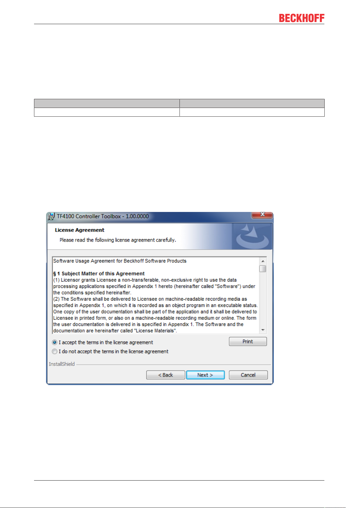
ð The installation dialog opens.
2. Accept the end user licensing agreement and click Next.
TF35508 Version: 1.0
Page 9
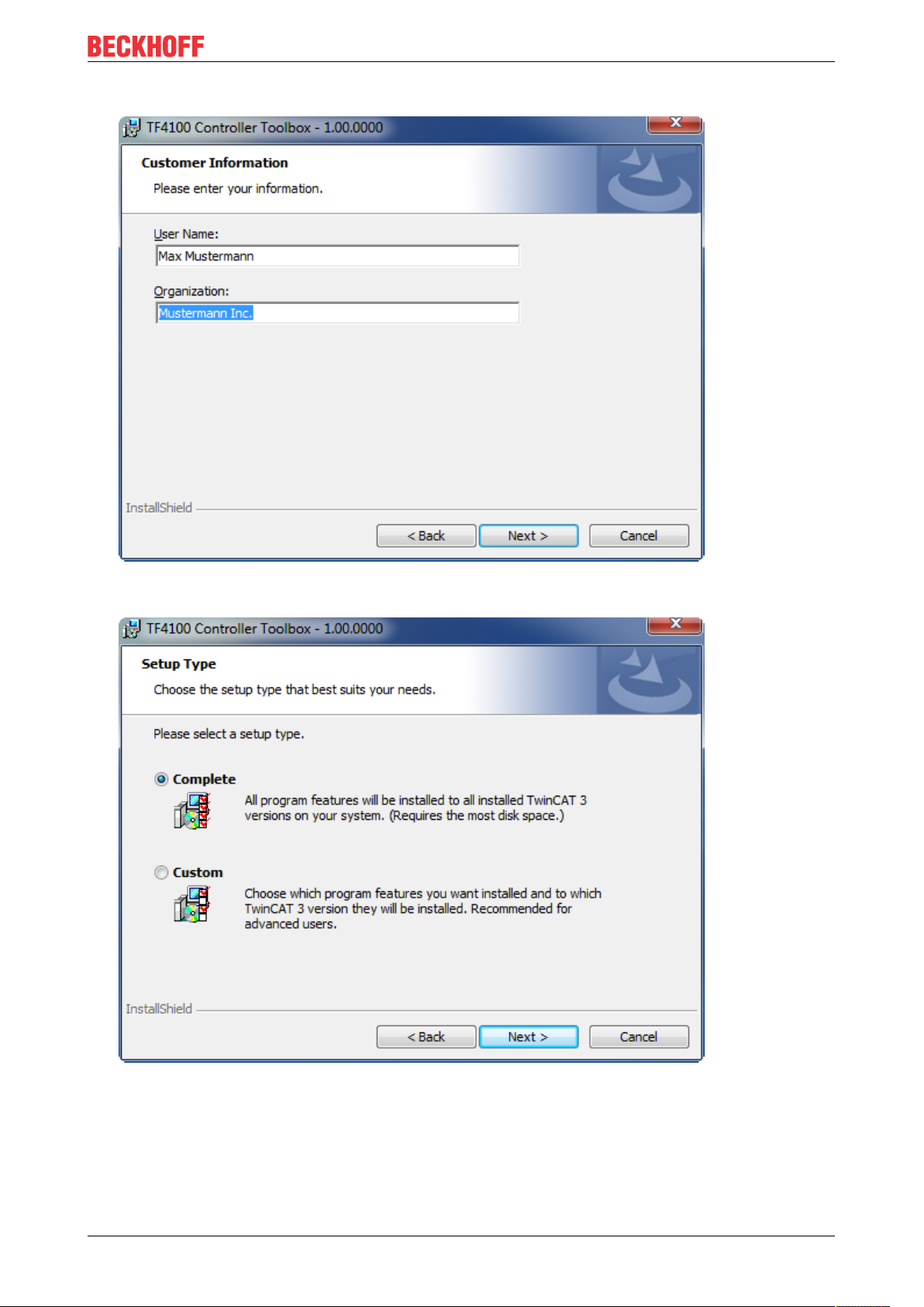
3. Enter your user data.
Installation
4. If you want to install the full version of the TwinCAT3Function, select Complete as installation type. If
you want to install the TwinCAT3Function components separately, select Custom.
TF3550 9Version: 1.0
Page 10
Installation
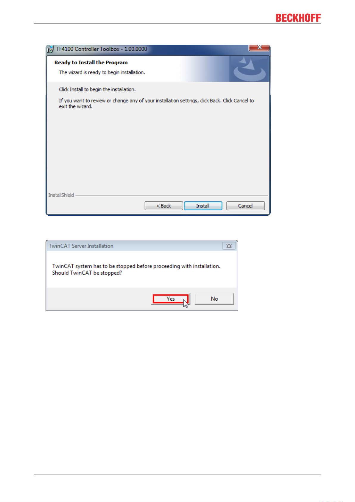
5. Select Next, then Install to start the installation.
ð A dialog box informs you that the TwinCAT system must be stopped to proceed with the installation.
6. Confirm the dialog with Yes.
TF355010 Version: 1.0
Page 11

7. Select Finish to exit the setup.
Installation
ð The TwinCAT3Function has been successfully installed and can be licensed (see Licensing [}11]).
3.3 Licensing
The TwinCAT3function can be activated as a full version or as a 7-day test version. Both license types can
be activated via the TwinCAT 3 development environment (XAE).
Licensing the full version of a TwinCAT3Function
A description of the procedure to license a full version can be found in the Beckhoff Information System in
the documentation "TwinCAT3Licensing".
Licensing the 7-day test version of a TwinCAT3Function
Note: A 7-day test version cannot be enabled for a TwinCAT 3 license dongle.
1. Start the TwinCAT 3 development environment (XAE).
2. Open an existing TwinCAT 3 project or create a new project.
3. If you want to activate the license for a remote device, set the desired target system. To do this, select
the target system from the Choose Target System drop-down list in the toolbar.
ð The licensing settings always refer to the selected target system. When the project is activated on
the target system, the corresponding TwinCAT 3 licenses are automatically copied to this system.
TF3550 11Version: 1.0
Page 12
Installation
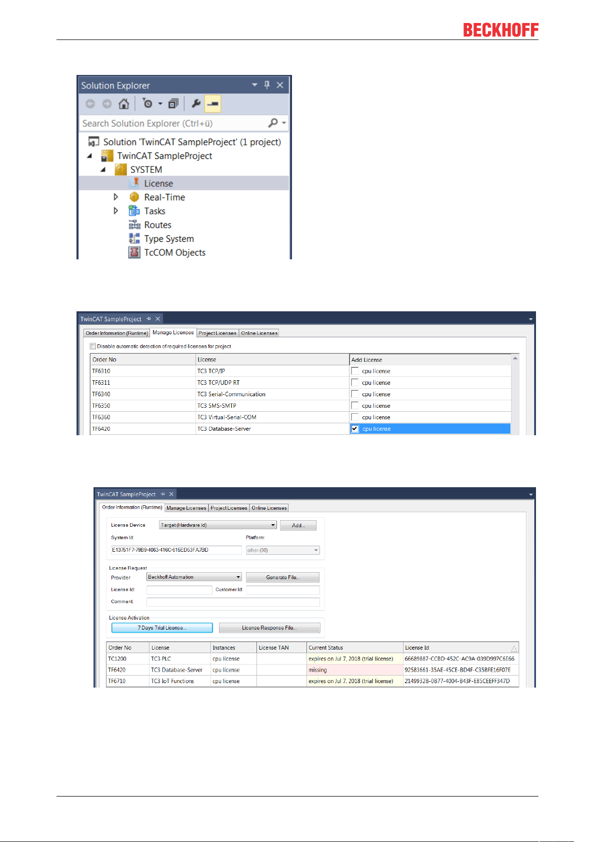
4. In the Solution Explorer, double-click License in the SYSTEM subtree.
ð The TwinCAT 3 license manager opens.
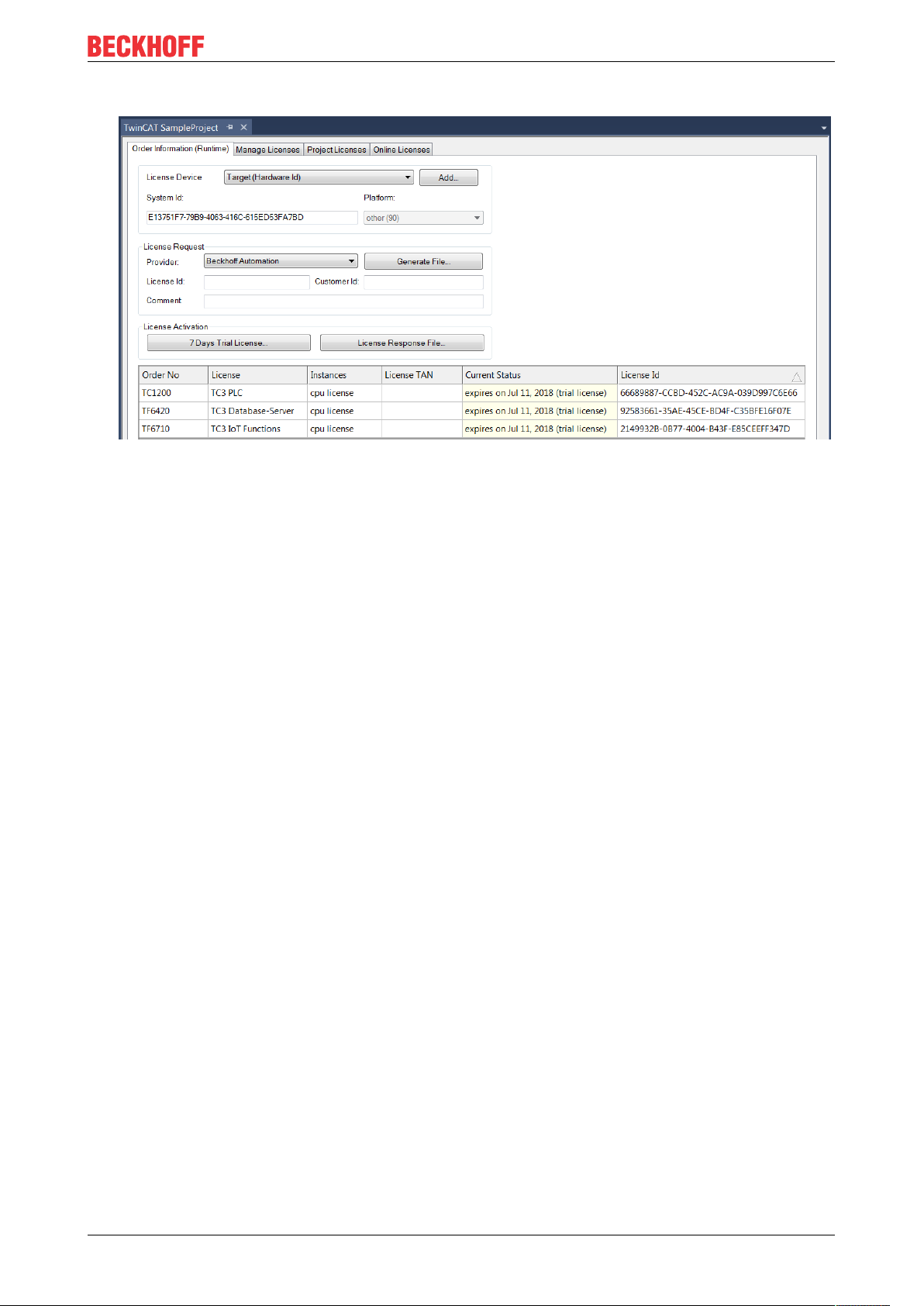
5. Open the Manage Licenses tab. In the AddLicense column, check the check box for the license you
want to add to your project (e.g."TF6420:TC3DatabaseServer").
6. Open the Order Information (Runtime) tab.
ð In the tabular overview of licenses, the previously selected license is displayed with the status
“missing”.
TF355012 Version: 1.0
Page 13
Installation
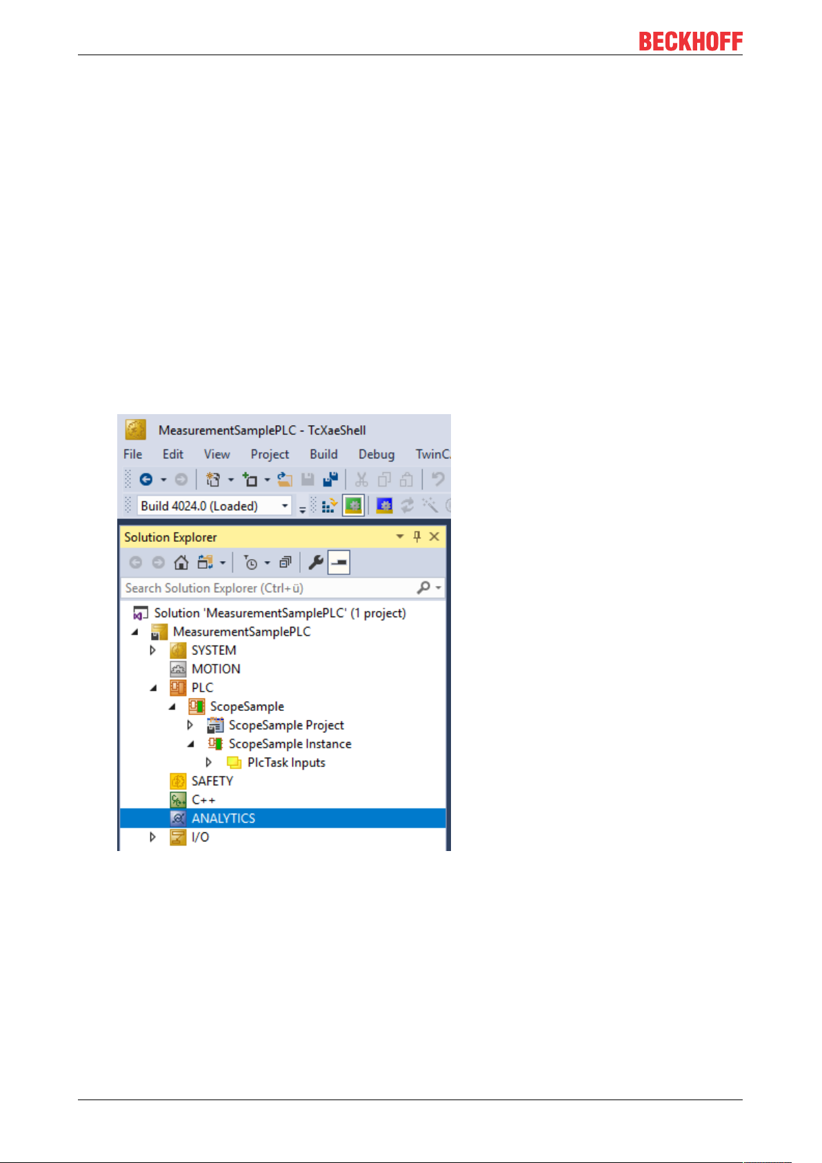
7. Click7-DayTrialLicense... to activate the 7-day trial license.
ð A dialog box opens, prompting you to enter the security code displayed in the dialog.
8. Enter the code exactly as it appears, confirm it and acknowledge the subsequent dialog indicating
successful activation.
ð In the tabular overview of licenses, the license status now indicates the expiry date of the license.
9. Restart the TwinCAT system.
ð The 7-day trial version is enabled.
TF3550 13Version: 1.0
Page 14
Analytics Workflow - First Steps
4 Analytics Workflow - First Steps
This step by step documentation presents the complete TwinCAT Analytics workflow. From the data
acquisition over the communication and historizing up to the evaluation and analysis of the data and to the
presentation of the data in web-based dashboard.
4.1 Recording data from the machine
On the machine side is the Analytics Logger the recorder of process data from the machine image, PLC, NC
and so on. The Logger is working in the real-time context of TwinCAT.
The TwinCAT Analytics Logger is installed with TwinCAT XAE and XAR. The Logger can act as MQTT Client
to communicate the recorded data to a native MQTT Message Broker or store the data in the same data
format in a local binary file. By the usage as MQTT Client the Logger is able to bypass short disconnects to
the Message Broker with a ring buffer functionality. You can configure a ring buffer as well for the local
binary file storage.
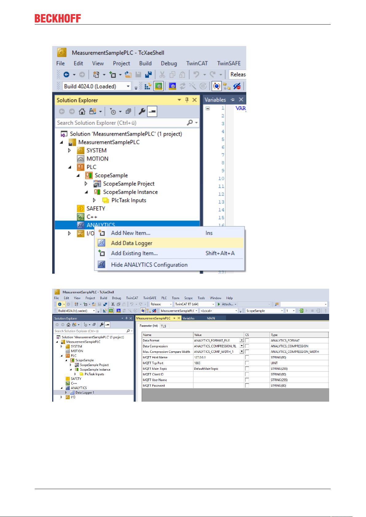
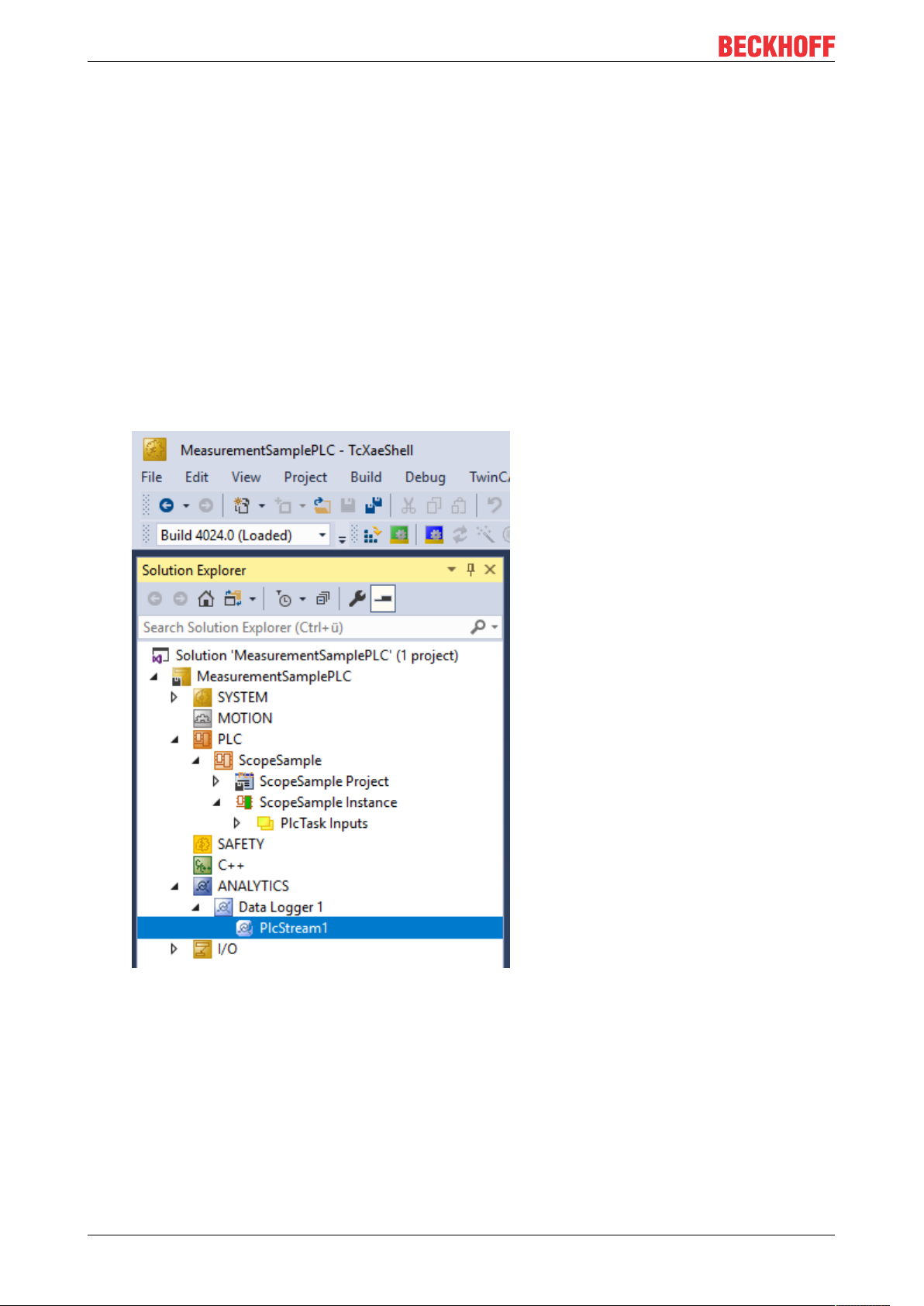
• To configure the Analytics Logger you have to navigate in your existing TwinCAT Project to the
Analytics tree node
TF355014 Version: 1.0
Page 15
Analytics Workflow - First Steps
• Right click on this node and click on “Add Data Logger” to add one new instance to your configuration
• For configuring the base settings, please double click on the new tree item
You can make your specific Analytics Logger settings
-Data Format: Binary file or MQTT stream
-FILE format: Analytics Logger stores the data in local binary files and all other settings are not
necessary anymore. The files will be stored in C:\TwinCAT\3.1\Boot\Analytics.
-BINARY: Data will be sent to the configured MQTT Message Broker. You can have multiple Logger in
one TwinCAT project to communicate data to different MQTT Message Broker.
-Data Compression: on (default) or off
TF3550 15Version: 1.0
Page 16
Analytics Workflow - First Steps
-Max Compression: mode of the compression
-MQTT host name
-MQTT Tcp port
-MQTT main topic for own hierarchical levels to keep the identification easy
-MQTT Client ID should be unique in the network
-MQTT username
-MQTT password to make authentication at the message broker
-At the TLS (Transport Layer Security) tab, security settings can be configured. TLS is a secure
communication channel between client and server. By the usage of certificates, the TCP port 8883 is
exclusively reserved for MQTT over TLS. Analytics Logger is supporting the modes CA Certificates, CA
Certificates & Client Certificate and Preshared Key (PSK) mode.
• If variables in your PLC application are marked in the declaration with the attribute {attribute
'TcAnalytics'} they will be shown automatically as a stream below the Data Logger tree node.
An additional device stream will be shown if your configuration provides an EtherCAT Process Image.
TF355016 Version: 1.0
Page 17
Analytics Workflow - First Steps
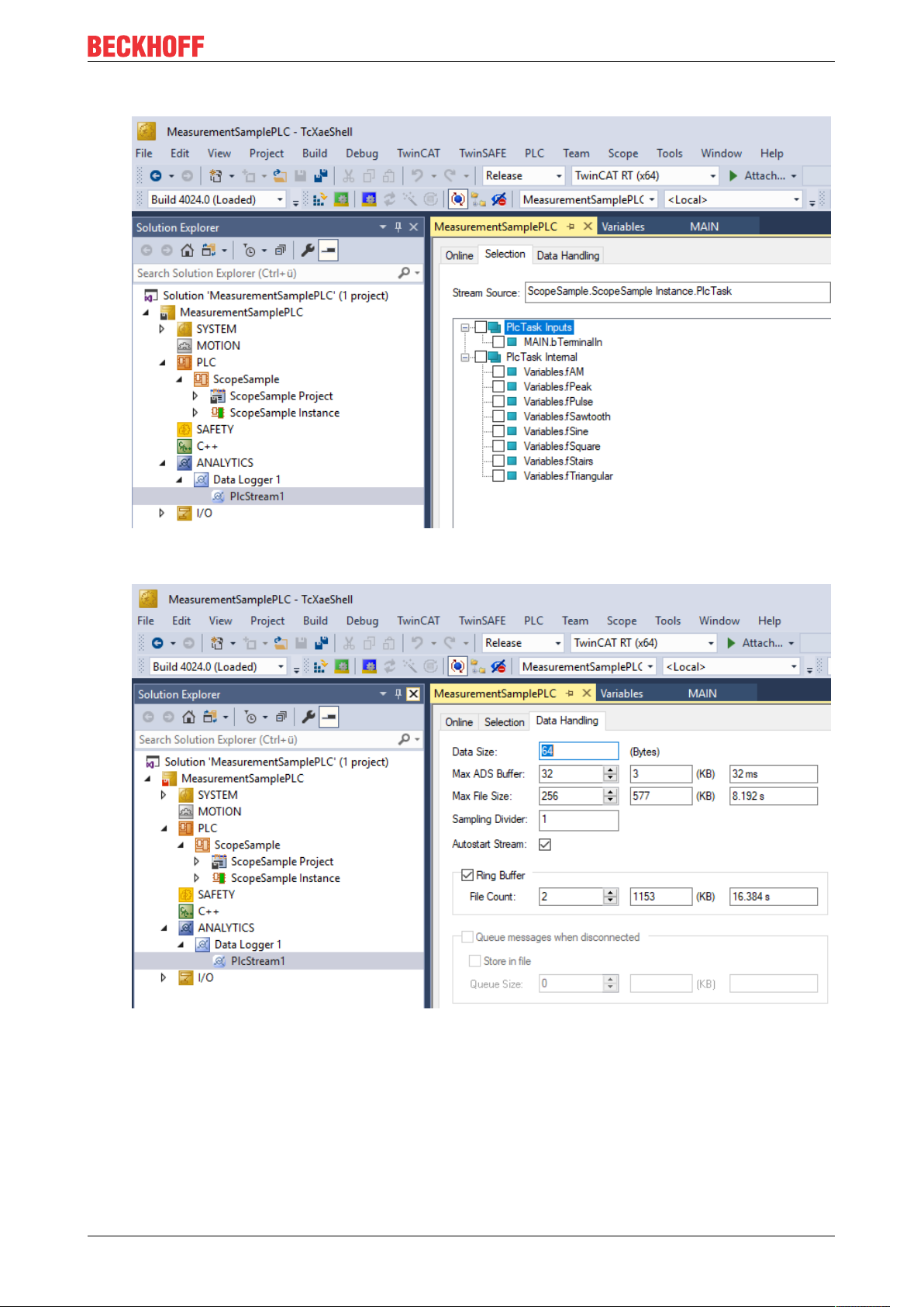
• In the stream a Selection tab is available to choose the variables that should be recorded
• Finally it is possible to change the package size for the frames or to configure the ring buffer for
disconnects and file in the Data Handling tab.
4.2 Communication
Currently, the Analytics workflow is fully mappable via MQTT. The engineering tools can also access the
data of the machines via ADS and carry out analyzes.
TF3550 17Version: 1.0
Page 18
Analytics Workflow - First Steps
If you choose for the IoT communication protocol MQTT you have to setup a native MQTT Message Broker
somewhere in the network (VM in a cloud system is also possible). This Message Broker provides a
decoupling of the different applications in the Analytics Workflow.
4.3 Historicize data
After installation of the TwinCAT Analytics Storage Provider you are able to configure the service running in
the background. You will find therefore the TcAnalyticsStorageProvider_Config application in the folder C:
\TwinCAT\Functions\TF3520-Analytics-StorageProvider\WinService.
TF355018 Version: 1.0
Page 19

Analytics Workflow - First Steps
The main part of the topic can be set in the configuration as well as the comment which will be used for
identification if more than one Storage Provider is registered at the Message Broker.
You are able to provide the Message Broker settings and to decide for storage type:
• Analytics File (binary file)
• Microsoft SQL
• Microsoft Azure Blob (Azure Cloud necessary)
Finally, you can save the config and start the service. The next step is the configuration of the specific
record. Therefore you should choose in your development environment the Storage Provider Recorder.
TF3550 19Version: 1.0
Page 20

Analytics Workflow - First Steps
The recorder has also to connect to the Message Broker. So you have to provide the same settings as for
the background service.
After this you can click to icon with the small cloud to search Storage Providers at the configured Message
Broker. Here you will find also the comment you gave already by the service configuration to identify your
Storage Provider.
TF355020 Version: 1.0
Page 21

Analytics Workflow - First Steps
The configuration of the record is very easy. You have just to choose your target in the Target Browser. Click
on Live data and choose one or more variables by multiselect and put them by drag and drop to the recorder
window.
The recorder will ask you if you like to add just the chose variables or the complete source process image of
the variables.
TF3550 21Version: 1.0
Page 22

Analytics Workflow - First Steps
You can also configure record names and a duration (otherwise endless until manual stop). A ringbuffer can
be set by memory or time.
Click the Start button to start the record. After this you can also disconnect the recorder, because the
background service do the work. It is also possible that someone else connect to this Storage Provider
service and control the running record.
TF355022 Version: 1.0
Page 23

Analytics Workflow - First Steps
After and also during the record you can choose the historical data as input for your analysis in the Target
Browser. In the Target Browser you will find for historical data a new control on the right hand site. There you
can choose the time span for your data.
4.4 Analyse data
Open your TwinCAT engineering environment to start the analysis of the data.
Open Visual Studio® >> File >> New >> Project…
Choose from TwinCAT Measurement the Analytics project template.
TF3550 23Version: 1.0
Page 24

Analytics Workflow - First Steps
The new project will be shown in the Solution Explorer. After a click on the Analytics Project tree node item a
start window opens where you can select your first action. From here, you can add a Network, open the
Toolbox, open the Target Browser or open the Analytics Storage Provider Recorder. You will do all these
actions in the following steps.
It makes sense to open in a first step the Toolbox of Visual Studio®. There you will find all the supported
algorithm of TwinCAT Analytics. Algorithm must be organized and grouped into networks. Right click on the
Analytics Project to add a new Network or add a Network using the start page. The first Network is always
generated by default.
If you click on the Network an editor will be open. Now you can take the algorithm you like by drag and drop
into the editor surface. After choosing the algorithm you need to connect input variables to the modules
(algorithm). Therefor open the Target Browser.
TwinCAT >> Target Browser >> Target Browser
TF355024 Version: 1.0
Page 25

Analytics Workflow - First Steps
Choose now the TcAnalytics or TcAnalyticsFile tab in the Target Browser. We go ahead with the TcAnalytics
tab (MQTT). Click on the green marked icon in the toolbar of this Analytics extension. A window will be open
where you can provide your Message Broker connectivity data.
Choose your MQTT Analytics client (TwinCAT Analytics Logger, TwinCAT IoT Data Agent or Beckhoff
EK9160). For each controller you have a unique ID. This ID is shown in the Target Browser. Not very legible,
of course. Therefore, click on the icon with the gear to get to the machine administration page. Here you can
provide a System Alias name which is shown in the Target Browser instead of the GUID.
In the next step you can choose between Live Data and Historical Data for each MQTT Analytics client.
Historical Data are only provided by the TwinCAT Analytics Storage Provider.
TF3550 25Version: 1.0
Page 26

Analytics Workflow - First Steps
You can take the variables by drag and drop into the inputs of the specific algorithm. For the most algorithm
it is possible to set conditions like thresholds, time intervals, logic operators and so on. You can do these
settings in the middle of each module.
Finally, your first Analytics Project is finished. To start the analysis, click on “Start Analytics”. To stop the
analysis, click on “Stop Analytics”.
TF355026 Version: 1.0
Page 27

Analytics Workflow - First Steps
Before starting Analytics or also during the runtime you can click on the button “Add Reference Scope”. A
Scope configuration is automatically built to fit your Analytics project.
Results of the analysis can be show in the Scope View charts by drag and drop. For example, an average
value can be shown as new channel in the view. Timestamps as Marker at the x-axes to show significant
values.
4.5 24h Analytics application
The last big step in the TwinCAT Analytics workflow is the continuous 24h machine analysis. It runs parallel
to the machine applications in the field. To do this in a very easy way the TwinCAT Analytics Workbench is
able to generate automatically a PLC code and a HTML5-based Dashboard of your Analytics configuration.
Both can be downloaded to a TwinCAT Analytics Runtime (TC3 PLC and HMI Server) and provide the same
analysis results as the configurator tool in engineering environment.
At first save your configuration and open the Analytics Deploy Runtime wizard. You can do this via the
context menu at the Analytics Project tree item or by the Start Page.
TF3550 27Version: 1.0
Page 28
Analytics Workflow - First Steps
When the wizard is open, there are some tabs available for you to click through. First one is called Solution.
Here it is possible to decide how you like to use your Analytics project in PLC code: As…
• completely new solution
• part of an existing solution
• update of an existing Analytics solution
In the TwinCAT PLC Target tab you can choose the ADS target system which runs the TwinCAT Analytics
Runtime (TF3550). The generated project is immediately executable. Therefore, you can set the option
Activate PLC Runtime. Also, that directly a boot project is created.
TF355028 Version: 1.0
Page 29

Analytics Workflow - First Steps
Specially for Virtual Machines it is important to run the project on isolated cores. Also, an option in this tab.
The next tab Results is only necessary if you have chosen the Stream Results option in the algorithm
properties. If you like to send results you can decide here in which way (local in a file/ by MQTT) and format
(binary/JSON). Also, this is generated automatically and starts running after activation.
TF3550 29Version: 1.0
Page 30

Analytics Workflow - First Steps
A down sampling of the results is possible by setting a cycle time. The next tab is reserved for the HMI
Dashboard. The prerequisite for the automatic Dashboard generation is the selection of HMI controls for the
corresponding algorithms whose results are to be displayed in the dashboard.
TF355030 Version: 1.0
Page 31

Analytics Workflow - First Steps
You can choose for your Analytics Dashboard different options like start page with a map, layouts, sorting
algorithm, own colors and logos. If you choose more languages for the Analytics controls a language switch
menu will be generated as well.
TF3550 31Version: 1.0
Page 32

Analytics Workflow - First Steps
Choose one of the installed Visual Studio versions. And whether the generation should start the instance
visibly or whether it should only be set up and activated in the background.
TF355032 Version: 1.0
Page 33

Analytics Workflow - First Steps
Finally you find a summery.
TF3550 33Version: 1.0
Page 34

Analytics Workflow - First Steps
Now you can click the Deploy button to start the generation process. The PLC project and the HMI
Dashboard will be generated now.
TF355034 Version: 1.0
Page 35

Analytics Workflow - First Steps
After the message Deploy Runtime succeeded you can find a new Visual Studio®/XAE Shell instance on
your desktop. The new Solution and both Projects are generated.
TF3550 35Version: 1.0
Page 36

Analytics Workflow - First Steps
TF355036 Version: 1.0
Page 37

Technical introduction
5 Technical introduction
Regarding the TwinCAT Analytics workflow the Analytics Runtime is able to make a continuous analysis of
data from different remote controller. The Analytics Runtime based on a standard TwinCAT PLC Runtime.
The application code can be generated automatically by the Analytics Workbench. So, the user has no
additional engineering effort, but is free to do code changes or to add own analysis code. The usage of other
standard Beckhoff PLC libraries like Tc3_Database or Tc3_ConditionMonitoring is possible, too.
Connection handling with remote devices
The number of devices/controller to be analyzed is limited. The Analytics Runtime itself allows four
connections to controller without additional packages.
Currently one connection is counted for the following controllers:
• Controller with TF3500 Analytics Logger
• Controller with TF6720 IoT Data Agent (can have many underlaid controllers)
• EK9160 IoT Coupler
If you need more than four connections in your application, you can add Controller Packs. Possible packs
are shown here [}7].
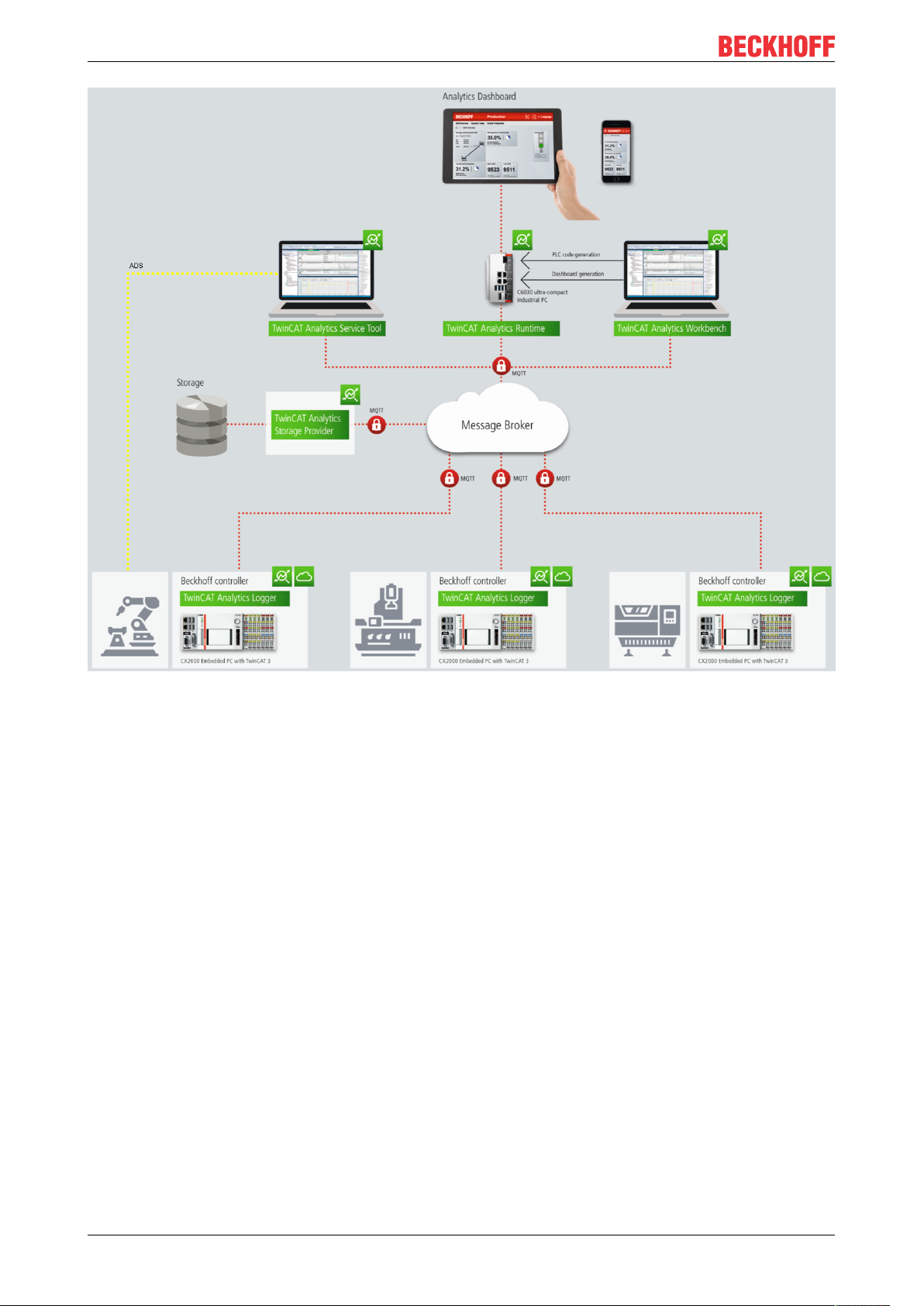
The picture below shows an application architecture with 11 connected controller. In this case you have to
order a license for Controller Pack 8 on the Analytics Runtime device/VM in addition to the TwinCAT
Analytics Runtime license.
TF3550 37Version: 1.0
Page 38

Technical introduction
TwinCAT HMI
Based on the analysis PLC code the engineer is able to design an own HTML5 dashboard with TE2000
which is integrated in the setup of TE3500 Analytics Workbench. The Analytics Runtime includes the HMI
Server. The HMI Server provides the HTML5 web pages for at least four clients at the same time. The
Server provides one client connection by himself and the Analytics Runtime includes the licence for the
Client Pack 3. Which gives you the possibility of 4 connections.
TF355038 Version: 1.0
Page 39

Configuration
6 Configuration
The configuration of the Analytics Runtime is carried out in the engineering tool TE3500 Analytics
Workbench. The necessary steps are explained again here. If you need more information about the
configuration in TE3500, please go to the documentation of TE3500.
6.1 Runtime deployment
It is possible to generate PLC code with all modules and parameters that are configured in the TwinCAT
Analytics Workbench Configurator. This code can be downloaded into a TwinCAT Analytics Runtime to
realize a 24/7 data analysis.
NOTE
Compatibility of auto generated PLC code
The auto generated PLC code is based on the TwinCAT Analytics Library. Interfaces of the base models of
the library will be compatible with previous versions after release of the library. The auto generated code itself is just sample code! This code generation can change from version to version if necessary. As far as
possible it will be handled by code-Generation version.
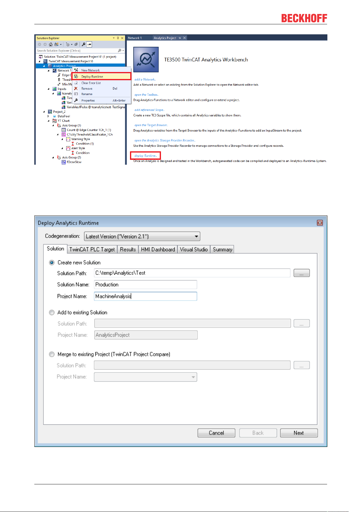
After configuration it is possible to click the command “Deploy Analytics Runtime” in the context command
like in the picture below.
The deploy wizard starts and it is possible to setup all needed configuration for the deployment step by step.
TF3550 39Version: 1.0
Page 40

Configuration
At the first tab “Solution” you are able to choose if a new solution will be generated or if a new project will be
added to an existing solution or if the new project has to be merged to an existing project.
At the second tab “TwinCAT PLC Target” all PLC specific parameter can be set like Target System or Task
cycle time.
TF355040 Version: 1.0
Page 41

Configuration
If you have set the “PLC Result” property of some functions in the configurator, the “Result” tab is included to
the deploy wizard. There it is possible to setup where the results can be streamed or stored.
TF3550 41Version: 1.0
Page 42

Configuration
If “Select Result Items” is clicked, it is possible to select only the values you want.
TF355042 Version: 1.0
Page 43

Configuration
On the next tab “Visual Studio” you can choose which Visual Studio version or TwinCAT XAE Shell should
be used for generating if you have installed more than one.
The last tab shows you all settings you made for the generating. Now you can start the generation process
with a click on Deploy.
TF3550 43Version: 1.0
Page 44

Configuration
The overview window will show you every step during the generation process.
6.1.1 Algorithm properties
Each algorithm of the Analytics Configurator is providing some properties. The sections of HMI and PLC are
necessary for the automatic code generation.
TF355044 Version: 1.0
Page 45

Configuration
HMI
• Generate GVL: Enable the generation of an Global Variable List with a collection of variables and
corresponding data type mapping for TwinCAT HMI
• GlobalVariableType: Choose the type with InOutVariables just for inputs and outputs of the algorithm
or KeyValuePairs for general mapping to STRING for tables
•
PLC
• Persistent Results: Enable this flag to store results of algorithm persistent to target system of the
Analytics Runtime
• Stream Results: Enable this flag to add the In- and Outputs of the algorithm to a result stream which
will be generated by the code generation
6.1.2 PLC Code
NOTE
Compatibility of auto generated PLC code
The auto generated PLC code is based on the TwinCAT Analytics Library. Interfaces of the base models of
the library will be compatible with previous versions after release of the library. The auto generated code its
self is just sample code! This code generation can change from version to version if necessary.
Folder structure in the generated plc project:
TF3550 45Version: 1.0
Page 46

Configuration
Task:
For the analytics analysis a separated task will be generated.
TF355046 Version: 1.0
Page 47

Configuration
StreamHelper:
If one or more data source are type of mqtt binary stream, the code generation will create an instance of a
StreamHelper object to handle the incoming binary stream samples.
DataTypes:
The datatypes are created for the analysis. They contain structs for the reset functionality or result handling
and enums to select the different components.
HMI GVL:
To map comfortable in- and outputs of the modules with the HMI dashboard, selected variables will be
generated as global variable.
DataSource /M2M Mapping:
The DataSource FB manage the receiving of the input values of the different sources. In the OUTPUT
declaration you can find all configured inputs. The ValueMapping_M2M FB manage the value mapping
between the modules (M2M - Module to Module) from module INPUTs to module OUTPUTs
Network:
All modules are sorted in a specific network to get a better overview and structure of the configured analysis.
Modules:
The module FBs contains all inputs and outputs of the configured modules from the Workbench
Configurator. It is also possible to reconfigure the modules at runtime. You only have to change the
parameter and then start the reconfigure process with a rising edge at the bReconfigure INPUT.
Results:
If results of the analysis have to be stored or streamed, the result FB manages this and streams the selected
variables to the message broker or stores the data into the analytics binary file.
Analysis:
In the analysis FB the whole analytics routine is defined. All configured networks with their modules and error
handling are created.
MAIN:
In the MAIN_Analytics program the analysis FB is called. The program is assign to the separated Task.
It is also possible to reset single modules, whole networks or all defined networks with only one rising flag.
First you have to choose the component you would like to reset. Then a rising edge at the bReset INPUT
starts the reset process.
Inside of the A_Reset Action all reset calls are defined.
6.1.2.1 Code version 2.0
Requirements
Development environment Target platform Plc libraries to include
TwinCAT v3.1.4024.0 PC or CX (x64, x86) Tc3_Analytics Version >= 3.1.0.0
TF3550 47Version: 1.0
Page 48
Configuration
6.1.2.1.1 MAIN_Analytics
In the MAIN_Analytics program the analysis FB is called. The program is assign to the separated Task.
It is also possible to reset single modules, whole networks or all defined networks with only one rising flag.
First you have to choose the component you would like to reset. Then a rising edge at the bReset INPUT
starts the reset process.
Inside of the A_Reset Action all reset calls are defined.
Syntax
Definition:
PROGRAMMAIN_Analytics
VAR_INPUT
stReset: ST_AnalysisReset;
END_VAR
VAR_OUTPUT
bError: BOOL;
ipTcResult: I_TcMessage;
END_VAR
Requirements
Development environment Target platform Plc libraries to include
TwinCAT v3.1.4024.0 PC or CX (x64, x86) Tc3_Analytics
6.1.2.1.2 FB_Analysis
In the analysis FB the whole analytics routine is defined. All configured networks with their modules and error
handling is created.
Syntax
Definition:
FUNCTION_BLOCKFB_Analysis
VAR_INPUT
[network FBs]
END_VAR
VAR_OUTPUT
bError: BOOL;
ipTcResult: I_TcMessage;
END_VAR
Inputs
Name Type Description
Network FBs FBs of the configured networks
Outputs
Name Type Description
bError BOOL Becomes TRUE as soon as an error situation
occurs.
ipTcResult I_TcMessage Message interface from the TwinCAT 3
EventLogger, which provides details on the return
value.
TF355048 Version: 1.0
Page 49
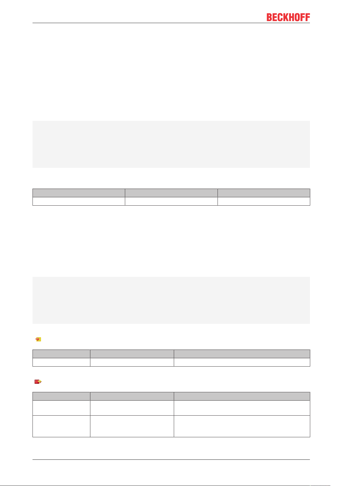
Methods
Name Definition location Description
Call [}49]
Local Method for background communication with the
TwinCAT driver. The method must be called
cyclically.
Reset [}49]
ResultStream [}50]
Local Reset the whole analysis
Local Optional: If a result stream has to be created
Requirements
Development environment Target platform Plc libraries to include
TwinCAT v3.1.4024.0 PC or CX (x64, x86) Tc3_Analytics
Call
Syntax
METHODCall:BOOL
VAR_INPUT
ipDataSource: I_T[n]_DataSource;
END_VAR
Configuration
Inputs
Name Type Description
ipDataSource I_T[n]_DataSource Data for the analysis.
Return value
Name Type Description
Call BOOL
Reset
Syntax
METHODReset:BOOL
VAR_IN_OUT
stReset: ST_AnalysisReset;
END_VAR
Inputs
Name Type Description
stReset ST_AnalysisReset Struct to define witch module or
network should be reset.
Return value
Name Type Description
Reset BOOL Is TRUE if done
TF3550 49Version: 1.0
Page 50

Configuration
ResultStream
Syntax
METHODResultStream:BOOL
VAR_INPUT
ipResults: I_Results;
END_VAR
Inputs
Name Type Description
ipResults I_Results Interface pointer to the Result FB
Return value
Name Type Description
Call BOOL
6.1.2.1.3 FB_DataSource
The DataSource FB manage the receiving of the input values of the different sources. In the OUTPUT
declaration you can find all configured inputs.
Syntax
Definition:
FUNCTION_BLOCKFB_T[n]_DataSource IMPLEMENTS I_T[n]_DataSource
VAR
END_VAR
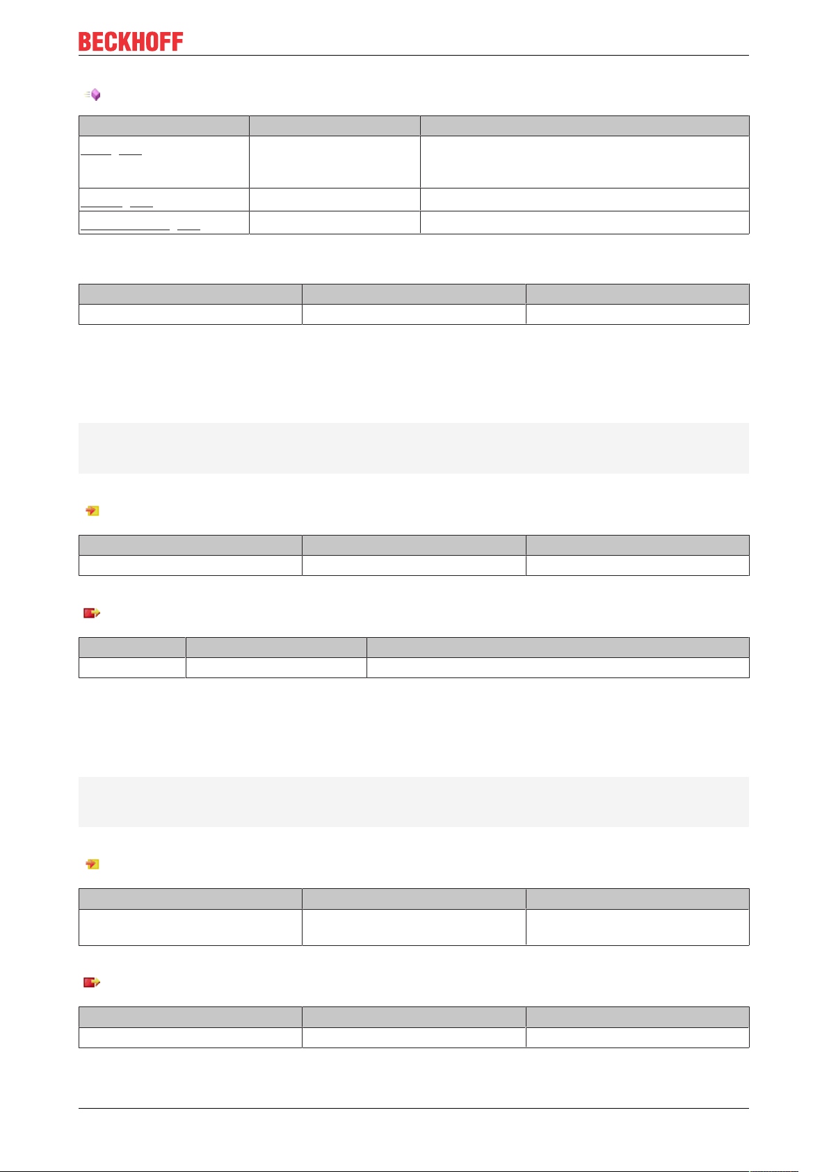
Methods
Name Definition location Description
Call [}51]
Local Method for background communication with the
TwinCAT driver. The method must be called
cyclically.
GetData [}50]
Local Method to get the data of the specified element
Requirements
Development environment Target platform Plc libraries to include
TwinCAT v3.1.4024.0 PC or CX (x64, x86) Tc3_Analytics
GetData
Syntax
METHODGetData:BOOL
VAR_INPUT
nElement:UDINT;
END_VAR
TF355050 Version: 1.0
Page 51

Configuration
Inputs
Name Type Description
nElement UDINT Element ID to get the specific
sample
Return value
Name Type Description
GetData BOOL Is TRUE if a new element is
selected
Call
Syntax
METHODCall:BOOL
Return value
Name Type Description
Call BOOL
6.1.2.1.4 FB_Network
All modules are sorted in a specific network to get a better overview and structure of the configured analysis.
Syntax
Definition:
FUNCTION_BLOCKFB_N[n]_[Network1]
VAR_INPUT
[module FBs]
END_VAR
VAR_OUTPUT
bError: BOOL;
ipTcResult: I_TcMessage;
END_VAR
Inputs
Name Type Description
Module FBs FBs of the configured modules
Outputs
Name Type Description
bError BOOL Becomes TRUE as soon as an error situation
occurs.
ipTcResult I_TcMessage Message interface from the TwinCAT 3
EventLogger, which provides details on the return
value.
TF3550 51Version: 1.0
Page 52
Configuration
Methods
Name Definition location Description
Call [}49]
Local Method for background communication. The method
must be called cyclically.
Reset [}49]
ValueMapping [}52]
SetHMIValues [}52]
Local Reset the Network with all sub modules
Local Map the input values to the different module inputs
Local Optional: Map in- outputs of the modules to the
global HMI variable
Requirements
Development environment Target platform Plc libraries to include
TwinCAT v3.1.4024.0 PC or CX (x64, x86) Tc3_Analytics
ValueMapping
Syntax
METHODValueMapping:BOOL
VAR_INPUT
ipDataSource:I_T[n]_DataSource;
END_VAR
Inputs
Name Type Description
ipDataSource I_T[n]_DataSource Data for the analysis from the
specific data source
Return value
Name Type Description
ValueMapping BOOL
SetHMIValues
Syntax
METHODSetHMIValues:BOOL
VAR_INPUT
pHMI_N[n]_[Network1]:POINTER TO ST_HMI_N[n]_[Network1];
END_VAR
Inputs
Name Type Description
pHMI_N[n]_[Network1] POINTER TO
ST_HMI_N[n]_[Network1]
Pointer to global HMI struct
Return value
Name Type Description
SetHMIValues BOOL Is TRUE if done
TF355052 Version: 1.0
Page 53

Reset
Syntax
METHODReset:BOOL
VAR
END_VAR
Return value
Name Type Description
Reset BOOL Is TRUE if done
Call
Syntax
METHODCall:BOOL
VAR_INPUT
ipDataSource: I_T[n]_DataSource;
[ipValueMapping_M2M: I_ValueMapping_M2M;]
END_VAR
Configuration
Inputs
Name Type Description
ipDataSource I_T[n]_DataSource Data for the analysis.
ipValueMapping_M2M I_ValueMapping_M2M Optional: Needed for mapping
values between modules
Return value
Name Type Description
Call BOOL
6.1.2.1.5 FB_Module
The module FBs contains all inputs and outputs of the configured modules from the Workbench
Configurator. It is also possible to reconfigure the modules at runtime. You only have to change the
parameter and then start the reconfigure process with a rising edge at the bReconfigure INPUT.
Syntax
Definition:
FUNCTION_BLOCKFB_N[n]_M[n]_[Module]
VAR_INPUT
[module inputs]
END_VAR
VAR_OUTPUT
bError: BOOL;
ipTcResult: I_TcMessage;
[module outputs]
END_VAR
TF3550 53Version: 1.0
Page 54

Configuration
Inputs
Name Type Description
Module inputs Inputs of the selected module
Outputs
Name Type Description
bError BOOL Becomes TRUE as soon as an error situation
occurs.
ipTcResult I_TcMessage Message interface from the TwinCAT 3
EventLogger, which provides details on the return
value.
Module outputs Outputs of the selected module
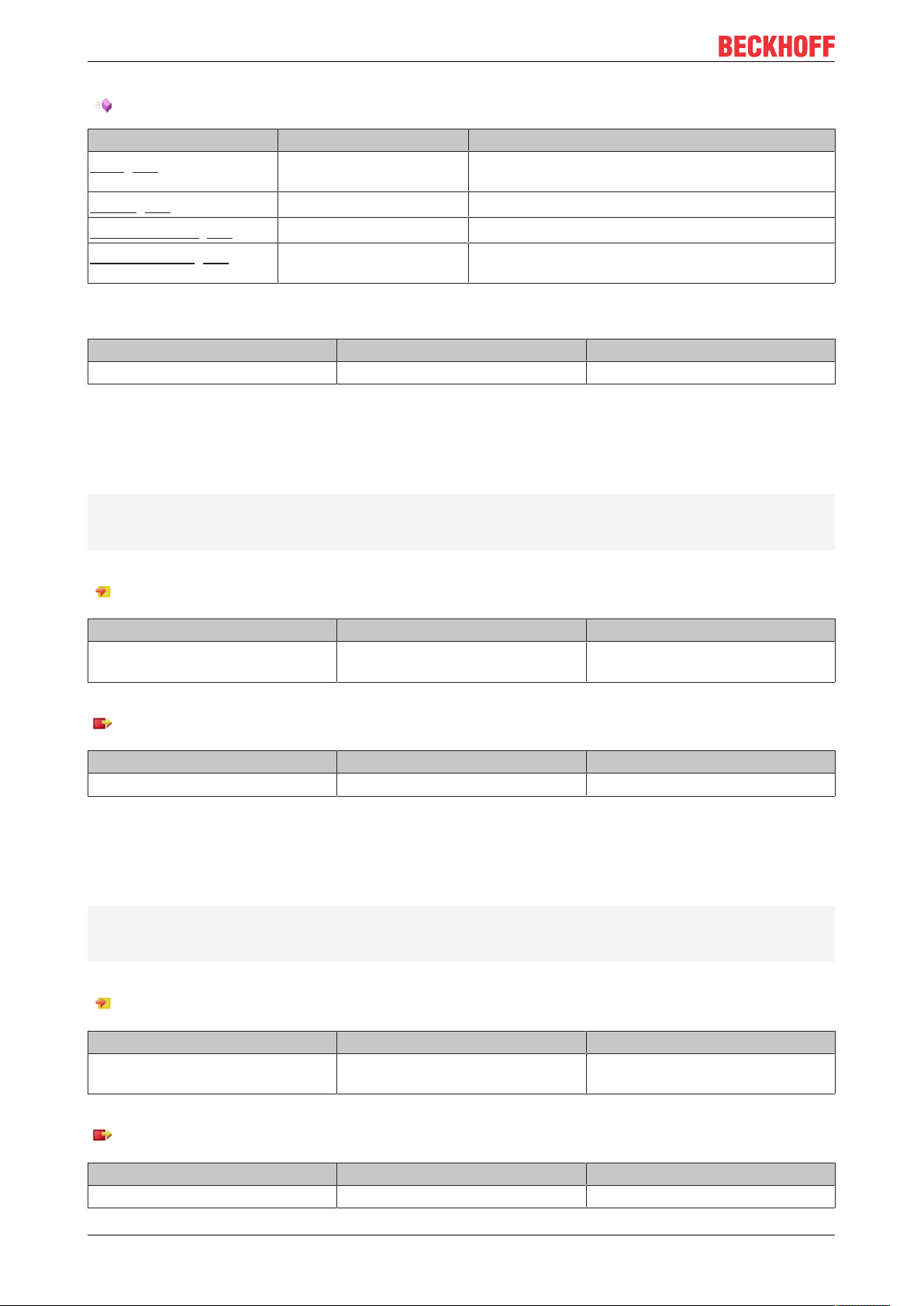
Methods
Name Definition location Description
Call [}54]
Local Method for background communication. The method
must be called cyclically.
Reset [}54]
SetHMI [}55]
Local Reset the module
Local Optional: Sets the in- outputs to the global HMI
structs
Requirements
Development environment Target platform Plc libraries to include
TwinCAT v3.1.4024.0 PC or CX (x64, x86) Tc3_Analytics
Call
Syntax
METHODCall:BOOL
VAR
END_VAR
Return value
Name Type Description
Call BOOL
Reset
Syntax
METHODReset:BOOL
VAR
END_VAR
TF355054 Version: 1.0
Page 55

Return value
Name Type Description
Reset BOOL Is TRUE if done
SetHMI
Syntax
METHODSetHMIValues:BOOL
VAR_INPUT
pHMI_N[n]_[Network1]:POINTER TO ST_HMI_N[n]_[Network1];
END_VAR
Inputs
Name Type Description
pHMI_N[n]_[Network1] POINTER TO
ST_HMI_N[n]_[Network1]
Pointer to global HMI struct
Configuration
Return value
Name Type Description
SetHMI BOOL Is TRUE if done
6.1.2.1.6 FB_Results
If results of the analysis has to be stored or streamed, the result FB managed this and streamed the selected
variables to the message broker or store the data into the analytics binary file.
Syntax
Definition:
FUNCTION_BLOCKFB_Results
VAR_OUTPUT
stResults: ST_Results;
END_VAR
Outputs
Name Type Description
stResults ST_Results Result struct which contains all items of the result
stream
Methods
Name Definition location Description
Call [}56]
Local Method for background communication. The method
must be called cyclically.
AddResult [}56]
SendResults [}56]
Release [}57]
Local Add a sample to the result stream
Local Sends all buffered samples of the result stream
Local Close stream or file of the result stream
TF3550 55Version: 1.0
Page 56

Configuration
Requirements
Development environment Target platform Plc libraries to include
TwinCAT v3.1.4024.0 PC or CX (x64, x86) Tc3_Analytics
Call
Syntax
METHODCall:BOOL
VAR
END_VAR
Return value
Name Type Description
Call BOOL
AddResult
Syntax
METHODAddResult:BOOL
VAR_INPUT
tTimestamp: ULINT;
stSample: ST_Results;
END_VAR
Inputs
Name Type Description
tTimestamp ULINT Timestamp of the sample
stSample ST_Results Sample struct
Return value
Name Type Description
AddResult BOOL
SendResults
Syntax
METHODSendResults:BOOL
VAR
END_VAR
Return value
Name Type Description
SendResults BOOL
TF355056 Version: 1.0
Page 57

Release
Syntax
METHODRelease:BOOL
VAR
END_VAR
Return value
Name Type Description
Release BOOL
Configuration
TF3550 57Version: 1.0
Page 58

Appendix
7 Appendix
7.1 FAQ - frequently asked questions and answers
In this section frequently asked questions are answered in order to make your work with TwinCAT Analytics
Runtime easier. If you have further questions, please contact our support team support@beckhoff.com.
It is possible to extend the number of connected HMI clients on the Analytics Runtime device? [}58]
?It is possible to extend the number of connected HMI clients on the Analytics Runtime device?
!Yes. Four HMI Clients are already included in the Analytics Runtime. But it is a standard TwinCAT system.
So you can book additional licenses like TF2030 Client Pack 10 or TF2040 Client Pack 25.
TF355058 Version: 1.0
Page 59

Page 60

More Information:
www.beckhoff.com/tf3550/
Beckhoff Automation GmbH & Co. KG
Hülshorstweg 20
33415 Verl
Germany
Phone: +49 5246 9630
info@beckhoff.com
www.beckhoff.com
 Loading...