

Page 1

Manual | EN
TF1910
TwinCAT 3 UML
8/19/2020 | Version: 2.3
Page 2

Page 3

Table of contents
Table of contents
1 Foreword ....................................................................................................................................................5
1.1 Notes on the documentation..............................................................................................................5
1.2 Safety instructions .............................................................................................................................6
2 Overview.....................................................................................................................................................7
3 Installation..................................................................................................................................................8
3.1 System requirements.........................................................................................................................8
3.2 Installation .........................................................................................................................................8
4 Settings.......................................................................................................................................................9
4.1 Options ..............................................................................................................................................9
4.2 UML compiler version......................................................................................................................10
5 Commands ...............................................................................................................................................13
5.1 Generate bitmap..............................................................................................................................13
5.2 Grid Enabled....................................................................................................................................14
5.3 Grid Disabled...................................................................................................................................15
6 UML Class Diagram.................................................................................................................................16
6.1 Basic principles................................................................................................................................16
6.2 Commands ......................................................................................................................................17
6.2.1 Creating a new class diagram ......................................................................................... 17
6.2.2 Adding existing elements to a diagram............................................................................ 18
6.2.3 Editing a class diagram.................................................................................................... 20
6.3 Editor ...............................................................................................................................................23
6.4 Elements..........................................................................................................................................23
6.4.1 Class................................................................................................................................ 24
6.4.2 Interface........................................................................................................................... 30
6.4.3 Global Variable List.......................................................................................................... 33
6.4.4 User-defined data type .................................................................................................... 35
6.4.5 Variable declaration ......................................................................................................... 38
6.4.6 Property ........................................................................................................................... 38
6.4.7 Method............................................................................................................................. 39
6.4.8 Composition..................................................................................................................... 39
6.4.9 Association ...................................................................................................................... 42
6.4.10 Implementation ................................................................................................................ 44
6.4.11 Generalization.................................................................................................................. 46
7 UML state diagram...................................................................................................................................49
7.1 Basic principles................................................................................................................................49
7.2 Commands ......................................................................................................................................51
7.2.1 Creating a new Statechart ............................................................................................... 51
7.2.2 Editing Statechart ............................................................................................................ 52
7.2.3 Go to definition................................................................................................................. 56
7.2.4 Find All References ......................................................................................................... 56
7.2.5 Add Watch ....................................................................................................................... 56
7.3 Editor ...............................................................................................................................................56
7.4 Elements..........................................................................................................................................57
TF1910 3Version: 2.3
Page 4

Table of contents
7.4.1 Start State........................................................................................................................ 57
7.4.2 End State ......................................................................................................................... 58
7.4.3 State ................................................................................................................................ 58
7.4.4 Composite State .............................................................................................................. 62
7.4.5 Fork.................................................................................................................................. 72
7.4.6 Choice.............................................................................................................................. 74
7.4.7 Transition ......................................................................................................................... 75
7.4.8 Completion Transition...................................................................................................... 77
7.4.9 Exception Transition ........................................................................................................ 78
7.5 Object Properties.............................................................................................................................81
7.6 Online Mode ....................................................................................................................................82
8 FAQ ...........................................................................................................................................................85
9 Samples....................................................................................................................................................87
9.1 UML class diagram..........................................................................................................................87
9.1.1 1 Basics ........................................................................................................................... 87
9.1.2 2 Simple machine ............................................................................................................ 87
9.2 UML state diagram ..........................................................................................................................88
9.2.1 1 Lamp............................................................................................................................. 88
9.2.2 2 Pedestrian traffic light ................................................................................................... 89
9.2.3 3 SaveText simulation ..................................................................................................... 90
9.2.4 4 Call Behavior - Basis .................................................................................................... 91
TF19104 Version: 2.3
Page 5

Foreword
1 Foreword
1.1 Notes on the documentation
This description is only intended for the use of trained specialists in control and automation engineering who
are familiar with applicable national standards.
It is essential that the documentation and the following notes and explanations are followed when installing
and commissioning the components.
It is the duty of the technical personnel to use the documentation published at the respective time of each
installation and commissioning.
The responsible staff must ensure that the application or use of the products described satisfy all the
requirements for safety, including all the relevant laws, regulations, guidelines and standards.
Disclaimer
The documentation has been prepared with care. The products described are, however, constantly under
development.
We reserve the right to revise and change the documentation at any time and without prior announcement.
No claims for the modification of products that have already been supplied may be made on the basis of the
data, diagrams and descriptions in this documentation.
Trademarks
Beckhoff®, TwinCAT®, EtherCAT®, EtherCAT G®, EtherCAT G10®, EtherCAT P®, Safety over EtherCAT®,
TwinSAFE®, XFC®, XTS® and XPlanar® are registered trademarks of and licensed by Beckhoff Automation
GmbH.
Other designations used in this publication may be trademarks whose use by third parties for their own
purposes could violate the rights of the owners.
Patent Pending
The EtherCAT Technology is covered, including but not limited to the following patent applications and
patents:
EP1590927, EP1789857, EP1456722, EP2137893, DE102015105702
with corresponding applications or registrations in various other countries.
EtherCAT® is a registered trademark and patented technology, licensed by Beckhoff Automation GmbH,
Germany
Copyright
© Beckhoff Automation GmbH & Co. KG, Germany.
The reproduction, distribution and utilization of this document as well as the communication of its contents to
others without express authorization are prohibited.
Offenders will be held liable for the payment of damages. All rights reserved in the event of the grant of a
patent, utility model or design.
TF1910 5Version: 2.3
Page 6
Foreword
1.2 Safety instructions
Safety regulations
Please note the following safety instructions and explanations!
Product-specific safety instructions can be found on following pages or in the areas mounting, wiring,
commissioning etc.
Exclusion of liability
All the components are supplied in particular hardware and software configurations appropriate for the
application. Modifications to hardware or software configurations other than those described in the
documentation are not permitted, and nullify the liability of Beckhoff Automation GmbH & Co. KG.
Personnel qualification
This description is only intended for trained specialists in control, automation and drive engineering who are
familiar with the applicable national standards.
Description of symbols
In this documentation the following symbols are used with an accompanying safety instruction or note. The
safety instructions must be read carefully and followed without fail!
DANGER
Serious risk of injury!
Failure to follow the safety instructions associated with this symbol directly endangers the life and health of
persons.
WARNING
Risk of injury!
Failure to follow the safety instructions associated with this symbol endangers the life and health of persons.
CAUTION
Personal injuries!
Failure to follow the safety instructions associated with this symbol can lead to injuries to persons.
NOTE
Damage to the environment or devices
Failure to follow the instructions associated with this symbol can lead to damage to the environment or
equipment.
Tip or pointer
This symbol indicates information that contributes to better understanding.
TF19106 Version: 2.3
Page 7

Overview
2 Overview
UML: general information
Unified Modeling Language (UML) is a graphical language that can be used for software analysis, design
and documentation. UML is particularly suitable for object-oriented implementations. The unified modelling of
the PLC application creates an easy-to-follow software documentation that can also be analyzed and
discussed by departments other than the Software Development Dept.
Diagram categories
Some of the UML diagrams can be categorized as structure diagrams, others as behavior diagrams.
Structure diagram are mainly used for static modelling and analysis, since they represent the software
architecture schematically. Behavior diagrams are used for dynamic modelling. They are executable models,
from which program code can be generated directly.
UML in TwinCAT 3.1 PLC
With the integration of UML (Unified Modelling Language) in TwinCAT 3.1, two additional editors for
modelling of PLC software are available. The existing TwinCAT PLC programming languages are extended
by the UML classes and the UML Statechart.
• : the functionality of the object UML class diagram
• : Programming a POU in the implementation language UML Statechart
UML class diagram
The UML class diagram belongs to the group of UML structure diagrams and can be used for schematic
representation of the software architecture. In this way it is possible to represent object classes and the
elements contained within them, as well as object relationships in a transparent manner.
UML Statechart
The UML Statechart is part of the UML behavior diagrams and is used for dynamic software modeling. It can
be used for a graphic specification of the dynamic response or the state-dependent system behavior.
Compilation of the statechart generates program code, so that the state machine can be executed directly.
The development process is supported by an online debugging option.
Advantages
There are many advantages to using UML diagrams for the analysis, design and/or documentation of
software. The essential aspects are covered in the following points:
• First of all, a graphic illustration that doesn't focus on technical details offers a good overview with
which to check software requirements before the implementation. This avoids an incomplete or
erroneous implementation of the application.
• The development of a well-conceived software architecture is greatly supported by the graphic
illustration of the control code. Such an architecture forms the basis for the simple and goal-oriented
implementation of even complex systems or requirements. Furthermore, a well-conceived software
architecture can contribute towards the development of autonomous modules that can be reused,
saving time and costs. In general, a well-planned software leads as a rule to fewer programming errors
and thus to a higher code quality.
• Graphic access to the software facilitates maintenance and debugging.
• An generally understandable documentation of the software is usually created with the help of UML
diagrams. On the one hand this can be used as a coordination tool in the development team, for
example to exchange ideas and concepts or to define requirements. On the other, UML diagrams can
be used to illustrate the control application to other technology specialists, for example mechanical
engineers or process technicians.
TF1910 7Version: 2.3
Page 8

Installation
3 Installation
3.1 System requirements
UML class diagram:
Development environment
TwinCAT v3.1.4018.16
UML statechart:
Development environment Target platform Library placeholder to include
TwinCAT v3.1.4016.0 PC or CX (x86, x64, ARM) UML statechart types
3.2 Installation
Engineering:
The engineering components of the function "TF1910 | TC3 UML" are contained in the TC3.1 XAE setup
(both UML classes and UML Statechart).
You can use these directly after installing the XAE. No license is required for this.
Runtime:
If the UML Statechart is used, the required runtime components are installed with the TC3.1 XAE or XAR
setup.
You will require the TF1910 runtime license for the additional runtime component UML Statechart. For
further information please refer to the documentation on Licensing.
You can test the UML Statechart with a 7-day test license without the license for TF1910. You can
continuously regenerate the trial license during the test phase. Refer here also to the documentation for the
TwinCAT-3 test licenses.
TF19108 Version: 2.3
Page 9
Settings
4 Settings
4.1 Options
In the TwinCAT UML options (Tools > Options >TwinCAT > PLC Environment > UML) you can configure
the settings relating to the UML editors for the entire project. Modified options take effect when the dialog is
closed, even in UML editors that are already open.
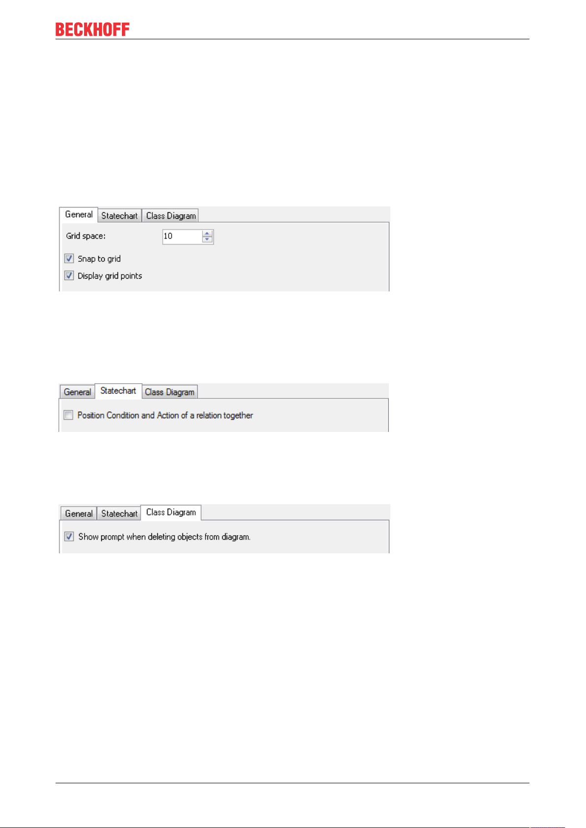
General
• Gridspace: enter a whole number that will be used as the gridspace in pixels. Default: 10
• Snap To Grid: activate this option in order to align all the elements in the UML editors to the grid.
• Display grid points: activate this option in order to display the grid points in the UML editors.
State chart
• Position Condition and Action of a relation together: activate this option in order to synchronously
shift a watchdog condition and an action that belong to the same transition in the statechart.
Class diagram
• Show prompt when deleting objects from diagram: objects can be deleted either only from the
diagram or from the diagram and from the project. There are two possible procedures for this:
◦ If an object is marked in the class diagram, two command symbols appear above the object in
order to delete the object from the diagram only or from both the diagram and the project.
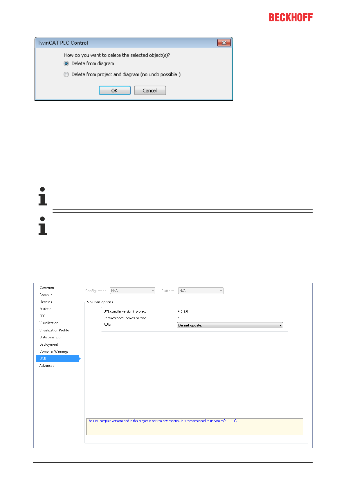
◦ Alternatively a marked object can be deleted by pressing the [Del] key. If the option to display a
selection window is deactivated, the object is deleted by default only from the diagram. If the
setting is activated, a selection window appears when deleting with which you can configure
whether the object should be deleted only from the diagram or also from the project.
TF1910 9Version: 2.3
Page 10
Settings
4.2 UML compiler version
The UML compiler version can be changed in the following dialogs:
• PLC project properties
• ProfileUpdate dialog
In addition, the following option is available with regard to the UML compiler version:
• Autoupdate UML Profile
The UML compiler version is only relevant if the UML Statechart language is used.
Scope of the setting “UML compiler version”
The setting of the UML compiler version is a “solution option” and therefore does not only affect the
PLC project, whose properties you are currently configuring, i.e. set UML compiler version applies
to all PLC projects in the development environment.
PLC project properties
You can change the UML compiler version in the properties of the PLC project.
Open the PLC project properties and click on the category UML.
TF191010 Version: 2.3
Page 11
Settings
• UML compiler version in project: Indicates the UML compiler version currently used in the project.
• Recommended, newest version: Indicates the latest available UML compiler version, whose
application is recommended.
• Action: In this dropdown menu you can select the required action. The action is executed directly
when you select it. Example actions:
◦ Do not update.
◦ Update to 4.0.2.1
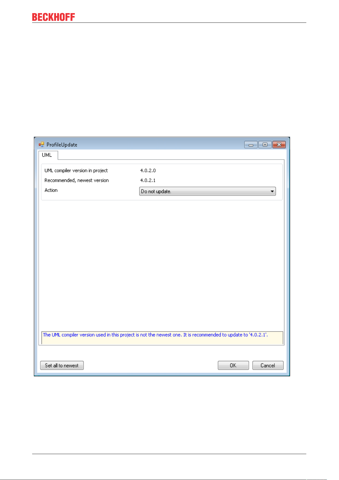
ProfileUpdate dialog
If you open a PLC project, in which an outdated UML compiler version is used, a corresponding warning
appears in the message window (“New version found for UML”). Double-click this warning to open the
ProfileUpdate dialog, in which you can change the UML compiler version.
• UML compiler version in project: Indicates the UML compiler version currently used in the project.
• Recommended, newest version: Indicates the latest available UML compiler version, whose
application is recommended.
• Action: In this dropdown menu you can select the required action. The action is executed when the
dialog is confirmed via OK. Example actions:
◦ Do not update.
◦ Update to 4.0.2.1
• Set all to newest: Click the button to set the UML compiler version to the latest version.
TF1910 11Version: 2.3
Page 12
Settings
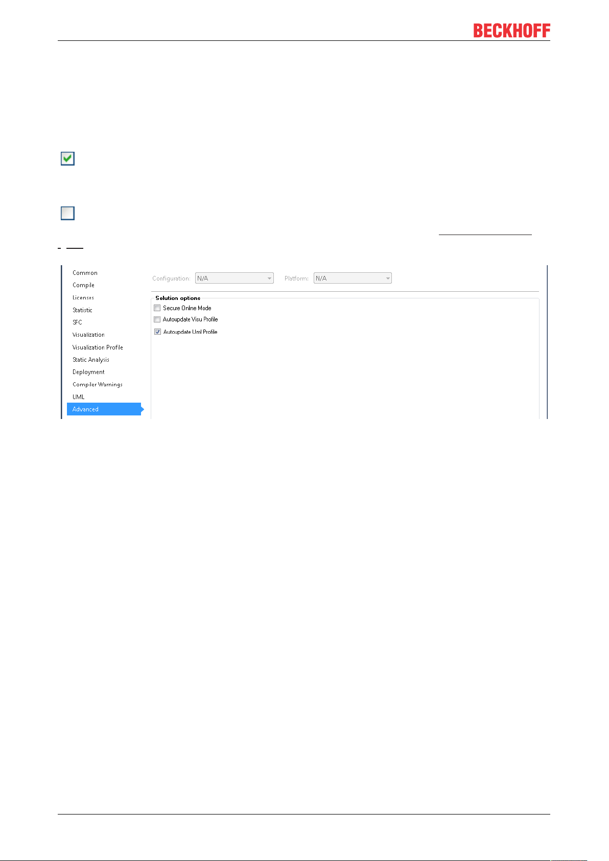
Autoupdate UML Profile
The option Autoupdate UML Profile is available in the Advanced category of the PLC project properties. It
can be used to configure the automatic update behavior of the UML compiler version.
If you open a PLC project, in which an outdated UML compiler version is used, a corresponding warning
appears in the message window (“New version found for UML”).
: In such a case, the UML compiler version is automatically set to the latest version, if the option
Autoupdate UML profile is enabled. On such an automatic update of the UML compiler version, the
message window shows a corresponding warning (e.g. “UML set from '4.0.2.0' to '4.0.2.1'”).
: If the option Autoupdate UML Profile is disabled, the UML compiler version is not changed
automatically. Double-click on the warning “New version found for UML” to open the ProfileUpdate dialog
[}11], in which you can change the UML compiler version manually.
TF191012 Version: 2.3
Page 13

Commands
5 Commands
Common commands for all UML diagrams
If a UML diagram is selected in the project tree, the following command is available in the context menu:
• Generate bitmap from the selected UML diagram [}13]
The alignment of the elements relative to a grid can be enabled or disabled within the editor of a UML
diagram.
• Grid activated [}14]
• Grid deactivated [}15]
5.1 Generate bitmap
The command Generate bitmap is available if
• the focus is on the project tree, and
• a class diagram or statechart is selected in the project tree and the context menu is open
Use the command in order to generate a diagram in BMP format from a class diagram or statechart and save
it in your file system.
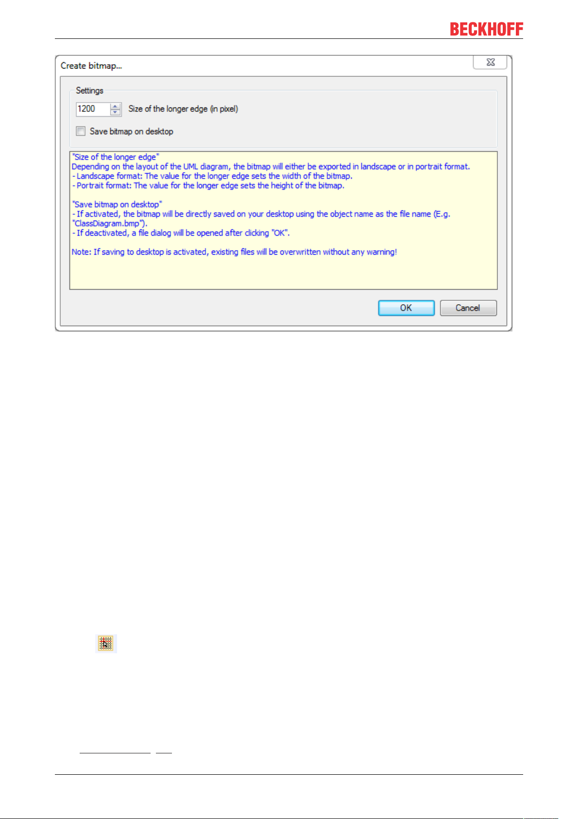
Executing the command Generate bitmap opens the corresponding dialog. This dialog offers the following
configuration options.
Size of the longer side (in pixels):
• The value that is displayed refers to the edge length of the bitmap. Depending on the layout of UML
diagram, the bitmap is exported in landscape or portrait format. If the diagram is in landscape format,
the value represents the length of the bitmap. If the diagram is in portrait format, the value represents
the height of the bitmap.
Save bitmap to desktop:
• : If this option is enabled, the object name is used as the file name, e.g. "FB_UML_SC.bmp" for an
object with the name "FB_UML_SC"
◦ Confirm the setting with [ OK ] to save the diagram to the desktop.
NoteThis option overwrites any existing files on the desktop with this name without
warning.
◦ Use [ Cancel ] to terminate the dialog without saving.
• : The name and the directory of the bitmap are editable
◦ Confirming the setting with [ OK ] opens the standard dialog for saving a file. Enter a directory and
file name and confirm the dialog with [ Save ]. The diagram is saved in your file system.
TF1910 13Version: 2.3
Page 14
Commands
Access by Automation Interface:
The command Generate bitmap is accessible on the POU node by Automation Interface using
ConsumeXML method.
<TreeItem>
<PlcPouDef>
<Commands>
<CreateBitmapCommand>
<Active>true</Active>
<Parameters>
<FileName>d:\tmp\Bitmap.png</FileName>
<Width>1200</Width>
<Height>-1</Height>(*1adaptstheheighttothewidthtokeeptheratio;
alternatively,youcanenterafixheightwhichmightdeformthebitmap*)
</Parameters>
</CreateBitmapCommand>
</Commands>
</PlcPouDef>
</TreeItem>
5.2 Grid Enabled
Symbol:
If this command is available in the context menu of a focused class diagram or statechart, an element is
aligned along the grid when changing its position. The option Snap to grid with grid space in the TwinCAT
UML options (Extras > Options > PLC Environment > UML) is ticked.
If you perform the command, the diagram will switch to Grid disabled. The option won't be ticked.
See also:
• “Grid Disabled” [}15]
TF191014 Version: 2.3
Page 15

Commands
• “Options [}9]”
5.3 Grid Disabled
Symbol:
If this command is available in the context menu of a focused class diagram or statechart, an element is
positioned without a grid when changing its position. Snap to grid with grid space in the TwinCAT UML
options (Extras > Options > PLC Environment > UML) is not ticked.
If you perform the command, the diagram will switch to Grid enabled. The option will be ticked.
See also:
• “Grid Enabled” [}14]
• “Options [}9]”
TF1910 15Version: 2.3
Page 16
UML Class Diagram
6 UML Class Diagram
In addition to the following information, please also note the samples [}87] that give a first introduction to
the tool.
6.1 Basic principles
The UML class diagram can be used to document, analyze, design and expand the structure of a (complex)
system. In the process, classes can be designed and relationships between them can be mapped. The clear
illustration of PLC program elements includes a.o. inheritance and implementation relationships, so as to
clearly visualize interrelationships. A UML class diagram is therefore ideal for graphical system
documentation and offers a comprehensible basis for conveying technical content.
The class diagram editor provides elements that map the object orientation of the project. Since the editor is
embedded in the PLC area of the TwinCAT 3 development environment, automatic generation of code is
possible. An extensive range of features and tools is integrated.
The class diagram can be used in two directions. The existing project structure can be imported into the
class diagram, or selected elements of the existing project structure can be added to the class diagram. As a
result, the already existing software architecture can be documented and analyzed. Secondly, the class
diagram offers the possibility to change and expand existing PLC elements or the existing project structure.
This modification can be carried out with the aid of the class diagram editor [}23] and the associated
elements [}23] of the toolbox. These allow the software architecture to be changed and expanded and at
the same time to be documented and analyzed.
Terms from the object orientation Synonym in IEC 61131-3
Class (UML: class) POU types:
• Program (PRG): PROGRAM
• Function block (FB): FUNCTION_BLOCK
• Function (FUN): FUNCTION
Attribute (UML: attribute)
• Internal variable
• Parameter: {input}
• Property: {property}
• Output Parameters: {output}
Operation (UML: operation) • Method: METHOD
Interface (UML: interface) Interface: INTERFACE
Synchronicity
Objects in the class diagram and the project are kept in sync, so that user inputs affect both views. This
means the corresponding objects in the project tree are changed automatically when objects are changed
via the class diagram. On the other hand, modifications in the project tree automatically become visible in the
class diagram, if the corresponding objects are shown in the class diagram.
Variable types:
• Variables: VAR
• Input variables: VAR_INPUT
• Property: PROPERTY
• Output variables: VAR_OUTPUT
• Action
Global variable list (GVL): VAR_GLOBAL
User-defined data type (DUT): TYPE
Application options
In general, the following applies:
• Not all elements of a project have to be shown in the class diagram.
• Several class diagrams can be added to a project.
TF191016 Version: 2.3
Page 17

UML Class Diagram
In the interest of clarity it is generally preferable to show only a few objects in a class diagram. In this way it
is possible to create subject-related or project section-related class diagrams, as sample. The objects shown
can have particular dependencies, so that the objects and their dependencies are clearly displayed. On the
other hand, objects without explicit dependencies to one another can also be shown in a diagram, so that
they can be compared in parallel.
Based on this, the class diagram can be used for various purposes:
• As design and development tool
• As analysis tool for existing projects
• As project navigator
Information on which commands or actions can be used for the individual purposes is provided below.
As design and development tool
• Create a new, empty class diagram [}17].
• The class diagram can be edited [}20] by means of various action options.
→ All inputs also affect the objects in the project and are immediately visible in the project tree.
As analysis tool for existing projects
• Add existing elements to the class diagram [}18].
• Analyze the existing project structure with the aid of the class diagram you created and edit the
diagram [}20] if required.
→ All inputs also affect the objects in the project and are immediately visible in the project tree.
As project navigator
• Open a class diagram and double-click on an element in the class diagram to open the corresponding
editor.
• The declaration and implementation can be edited as usual, if required.
→ Any changes of the declaration are automatically updated in the class diagram.
Commands
The following commands or action options are available for the class diagram:
• Creating a new class diagram [}17]
• Adding existing elements to a diagram [}18]
• Editing a class diagram [}20]
Also note the commands, which are available for all UML diagrams: Common commands for all UML
diagrams [}13]
6.2 Commands
6.2.1 Creating a new class diagram
If you create a class diagram, you can optionally import the existing project structure. If this option is used, all
relevant objects are imported into the class diagram. Relevant objects are programs, function blocks,
functions, interfaces, DUTs, GVLs and their respective components (methods, properties, variables etc.).
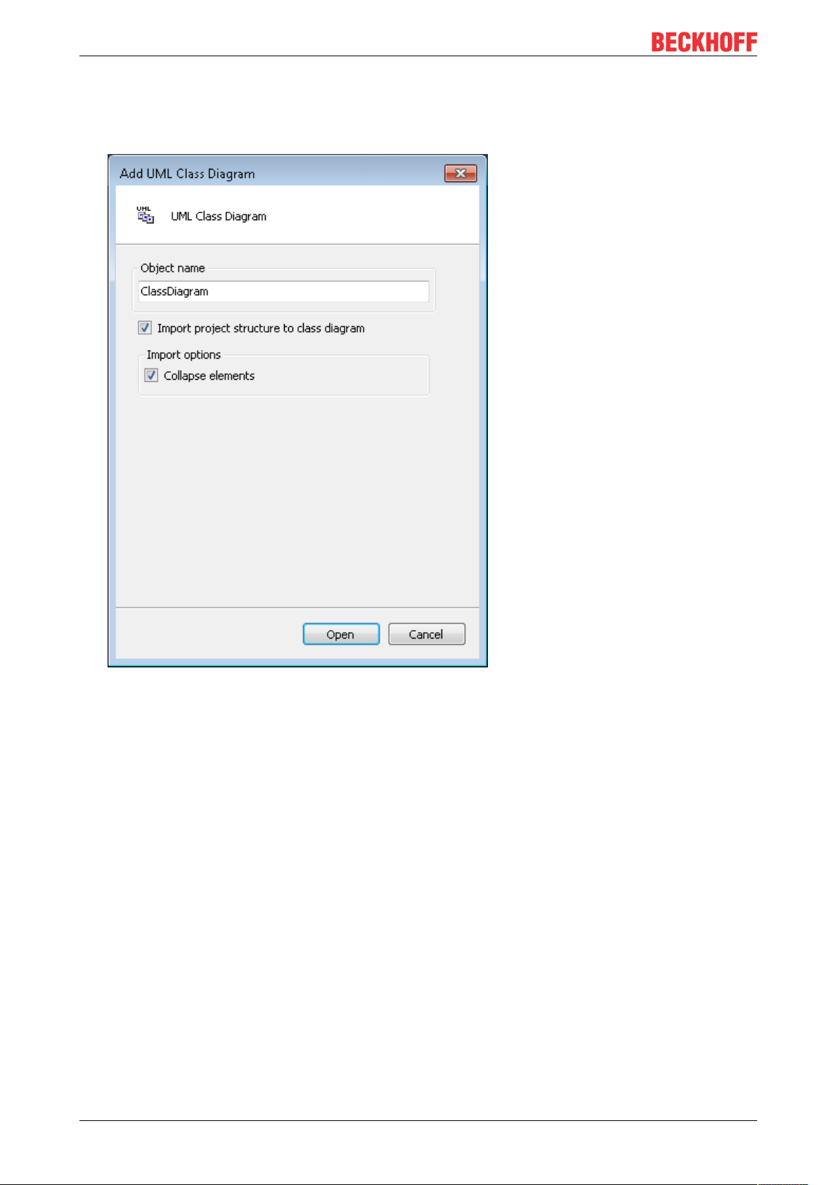
1. In the context menu of the project tree select the command Add object, then select the Class diagram
object.
2. In the Add UML class diagram dialog that opens enter a name for the class diagram.
3. Enable the option Import project structure into class diagram to import the existing project structure
into the new class diagram.
Disable the option to generate an empty class diagram.
TF1910 17Version: 2.3
Page 18
UML Class Diagram
4. Import options (only relevant for importing the project structure):
Enable the option Collapse elements to display the element details (attribute or operation list) in
minimized form.
Disable the option to display the element details in expanded form.
5. Confirm the inputs and configurations with the Open button.
ð The new class diagram object is added in the project tree, and the editor for the new diagram opens.
6.2.2 Adding existing elements to a diagram
Existing project elements can be added to a class diagram in a number of ways. On the one hand, several
elements can be added simultaneously by importing the whole project structure or a selected folder via a
command. On the other hand, an individual element can be added by dragging & dropping it onto the class
diagram editor.
Depending on the number of elements, the following action options are available.
• Adding several existing elements:
◦ Import whole project structure when a new diagram is created
◦ Import whole project structure into an empty diagram
◦ Import whole folder structure into an empty diagram
• Adding an individual existing element:
◦ Visualize existing element from the project tree on the diagram
◦ Visualize existing element from the cross-references on the diagram
TF191018 Version: 2.3
Page 19
UML Class Diagram
Import whole project structure when a new diagram is created
1. Create a new class diagram [}17] and activate the option Import project structure into class diagram.
ð The new class diagram object is added to the project tree. The class diagram editor opens and shows
the class diagram for the existing project.
Import whole project structure into an empty diagram
1. Open an empty class diagram, which sits directly at the top project level in the project tree, not in a
project folder.
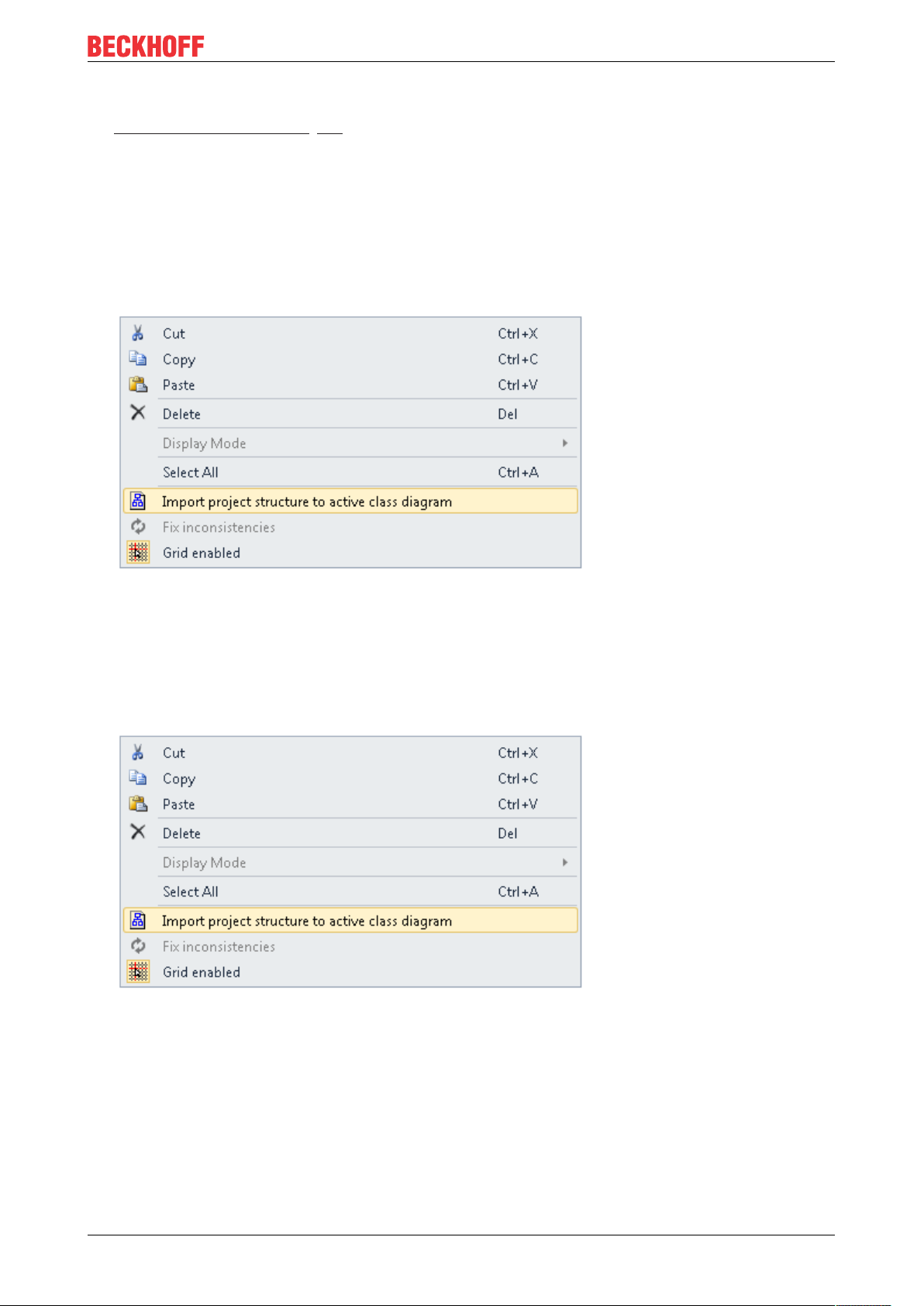
2. Execute the command Import project structure to active class diagram, which is available in the
context menu of the class diagram editor.
ð The class diagram shows the existing structure of the whole project.
Import whole folder structure into an empty diagram
1. Open an empty class diagram from the folder whose structure you want to import into the class diagram.
2. Execute the command Import project structure to active class diagram, which is available in the
context menu of the class diagram editor.
ð The class diagram shows the existing structure of the folder containing the class diagram.
Visualize existing element from the project tree on the diagram
1. Select an element of type POU, INTERFACE, GVL or DUT in the project tree and drag & drop it onto the
opened class diagram. Drop it in a suitable location to visualize it there.
ð The corresponding element is shown in the diagram. If relationships with already shown elements exist,
these are displayed automatically.
TF1910 19Version: 2.3
Page 20

UML Class Diagram
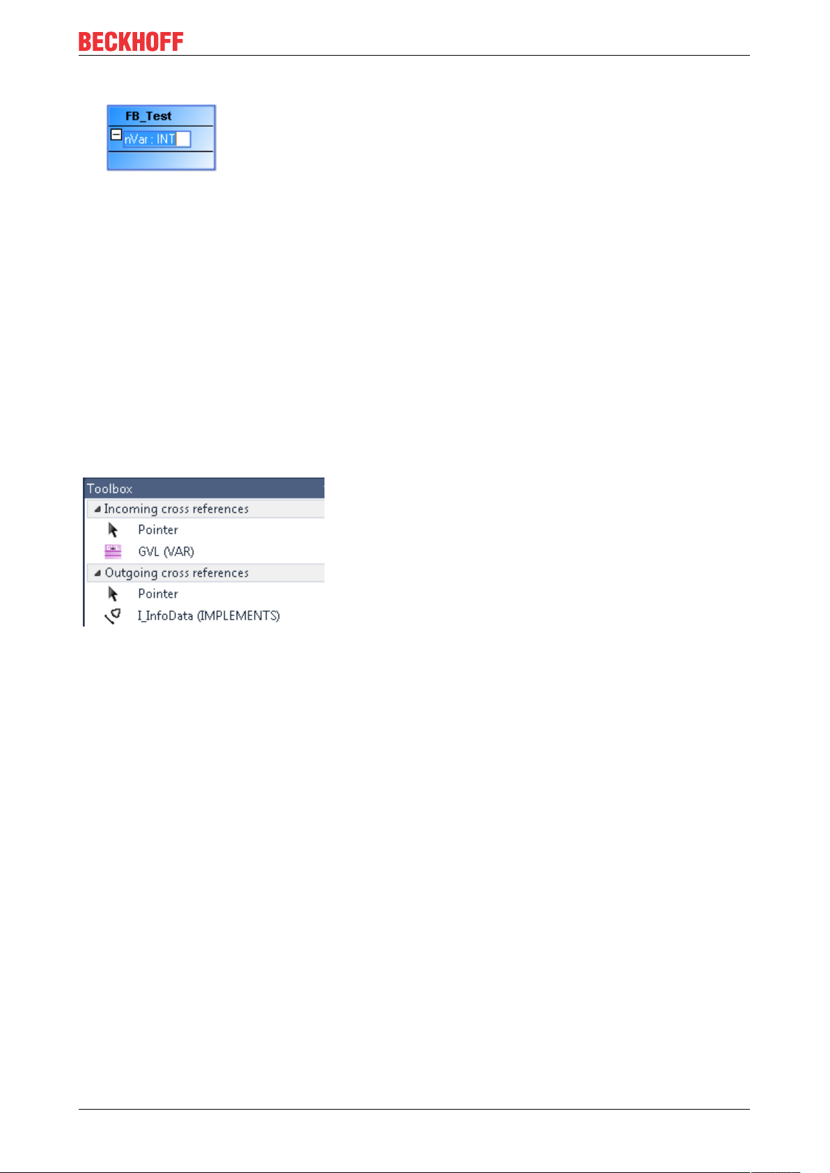
Visualize existing element from the cross-references on the diagram
The class element, which has a relationship with the selected element but is not included in the class
diagram, is shown in the Toolbox window under the heading Incoming cross-references or Outgoing
cross-references. First, the relationship type that links the two elements is shown as a symbol. This is
followed by the name of the target or source element. You can drag & drop the element onto the diagram, so
that the element is shown in the class diagram.
Showing cross-references
1. Open the Toolbox window via the View menu.
2. Select a rectangle element in the opened class diagram, which has relationships that are not shown in
the class diagram.
ð Under Toolbox the relationships with the elements are listed, which are not yet shown in the class
diagram. Under Incoming cross-references missing incoming relationships with source elements are
listed. Under Outgoing cross-references missing outgoing relationships are listed, together with target
elements.
Visualize existing element from the cross-references on the diagram
1. Drag & drop the element, which is listed under Incoming cross-references or Outgoing crossreferences and which is to be shown in the diagram, onto the class diagram. Drop it in a suitable
location to visualize it there.
ð The corresponding element is shown in the diagram. The relationships with the already shown elements
are displayed automatically.
6.2.3 Editing a class diagram
The actions available for editing a class diagram include the following. Further editing options can be found
under Editor [}23].
Adding a new element
1. Open the Tools window via the View menu.
2. Select an element [}23] in the Tools view and drag & drop it onto the opened class diagram. Drop it in
a suitable location to visualize it there.
ð The new element is created in the project tree and shown in the diagram.
Deselect “Toolbox” view
ü An element is selected in the Toolbox window. In the editor the cursor has the form of the selected ele-
ment.
1. Press the right mouse button.
ð The element is deselected, and the standard Pointer element is selected.
Editing identifiers
1. Open the line editor of an identifier with two single clicks.
TF191020 Version: 2.3
Page 21
UML Class Diagram
2. Enter a new name and confirm it via the [Enter] key or by clicking in an empty area of the diagram.
ð The identifier has the new name.
Visualize existing element from the project tree on the diagram
1. Select an element of type POU, INTERFACE, GVL or DUT in the project tree and drag & drop it onto the
opened class diagram. Drop it in a suitable location to visualize it there.
ð The corresponding element is shown in the diagram. If relationships with already shown elements exist,
these are displayed automatically.
Cross-references
The class element, which has a relationship with the selected element but is not included in the class
diagram, is shown in the Toolbox window under the heading Incoming cross-references or Outgoing
cross-references. First, the relationship type that links the two elements is shown as a symbol. This is
followed by the name of the target or source element. You can drag & drop the element onto the diagram, so
that the element is shown in the class diagram.
Showing cross-references
1. Open the Toolbox window via the View menu.
2. Select a rectangle element in the opened class diagram, which has relationships that are not shown in
the class diagram.
ð Under Toolbox the relationships with the elements are listed, which are not yet shown in the class
diagram. Under Incoming cross-references missing incoming relationships with source elements are
listed. Under Outgoing cross-references missing outgoing relationships are listed, together with target
elements.
Visualize existing element from the cross-references on the diagram
1. Drag & drop the element, which is listed under Incoming cross-references or Outgoing crossreferences and which is to be shown in the diagram, onto the class diagram. Drop it in a suitable
location to visualize it there.
ð The corresponding element is shown in the diagram. The relationships with the already shown elements
are displayed automatically.
Generate relationship between diagram elements
Option 1 – via icon:
1. Select an element in the opened class diagram.
2. Click on a relationship icon, which appears above the element (the selected element acts as source
element).
3. Click on the target element of the selected relationship.
TF1910 21Version: 2.3
Page 22

UML Class Diagram
ð You have created a relationship between the source and target element, which is active in the project
and shown in the diagram.
Option 2 – via Toolbox:
1. Click on a relationship element from Toolbox.
2. In the opened class diagram first click on the source element, then on the target element.
ð You have created a relationship between the source and target element, which is active in the project
and shown in the diagram.
Removing an element from the diagram
Option 1 – via icon:
1. Select the element in the class diagram, which you want to remove from the diagram.
2. Use the icon Remove from diagram, which appears above the element.
ð The selected element is removed from the diagram.
Option 2 – via the [Del] key
1. Select the element in the class diagram, which you want to remove from the diagram.
2. Press the [Del] key.
If the option [}9] Show prompt when deleting objects from diagram is disabled, the object is only
deleted from the diagram by default.
If the option is enabled, select the option “Remove from diagram” in the dialog that opens.
ð The selected element is removed from the diagram.
Removing an element from the diagram and the project
Option 1 – via icon:
1. Select the element in the class diagram, which you want to remove from the diagram and the project.
2. Use the icon Remove from project and diagram, which appears above the element.
ð The selected element is removed from the diagram and the project.
Option 2 – via the [Del] key
1. Enable the option [}9] Show prompt when deleting objects from diagram.
2. Select the element in the class diagram, which you want to remove from the diagram and the project.
3. Press the [Del] key and select the option Remove from project and diagram in the dialog that opens.
ð The selected element is removed from the diagram and the project.
As project navigator
1. Open a class diagram and double-click on an element in the class diagram.
ð The editor pertaining to the element opens.
2. If necessary, you can edit the declaration and implementation in the opened editor as usual.
ð Any changes of the declaration are automatically updated in the class diagram.
Multiple selections
• If Pointer is enabled in Toolbox (default), you can drag a rectangle over several elements in the class
diagram while pressing the left mouse button. All elements covered by the rectangle are then selected.
• Multiple selections are also possible by successively selecting the required elements while pressing the
[Ctrl] key.
• [Ctrl+A] or Select all selects all the elements within a rectangle, but no relationship elements.
TF191022 Version: 2.3
Page 23

UML Class Diagram
6.3 Editor
A UML class diagram visualizes the static structure of a project and the elements declarations.
For a special or filtered view of the project, you can drag a selection of objects from the project tree
into the class diagram, or selected elements can be removed from the diagram.
The class diagram can be edited through various actions. Further information on the editing options can be
found under Editing a class diagram [}20].
In addition, there are further, element-specific user inputs:
• Edit class [}25]
• Edit interface [}31]
• Edit generalization [}47]
• Edit realization [}45]
• Edit association [}43]
• Edit composition [}40]
6.4 Elements
The Tools window provides the elements of the class diagram. They can be added to the class diagram
window via drag & drop. The elements can be positioned freely.
Insert element
1. Open View > Tools to access the elements.
2. Drag an element into the class diagram window and drop it at a suitable location.
TF1910 23Version: 2.3
Page 24
UML Class Diagram
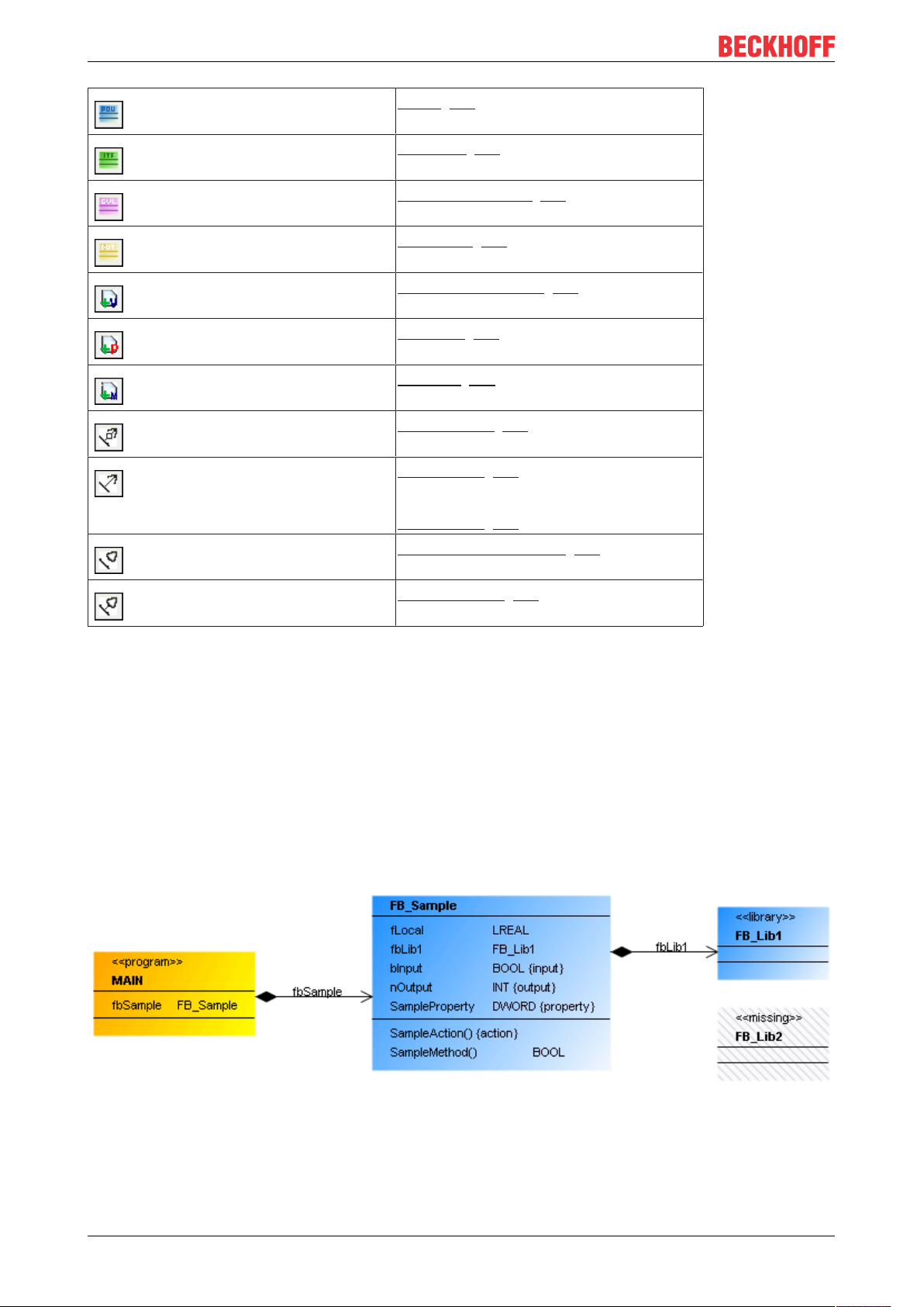
Class [}24] (POU)
Interface [}30]
Global variable list [}33] (GVL)
Data type [}35] (DUT)
Variable Declaration [}38]
Property [}38]
Method [}39]
Composition [}39] (VAR)
Association [}42] (POINTER)
or
Association [}42] (REFERENCE)
Realization relationship [}44]
(IMPLEMENTS)
Generalization [}46] (EXTENDS)
6.4.1 Class
A class is a logical unit in which data and operations are encapsulated. It also represents a variable type that
can be instantiated. A class can have an FB_Init method that is called when an instance is initialized.
A class can have the following relationship types:
• Composition: a class can contain other program elements.
• Association: a class can know other program elements.
• Realization: a class can implement an interface.
• Generalization: a class can inherit from another class.
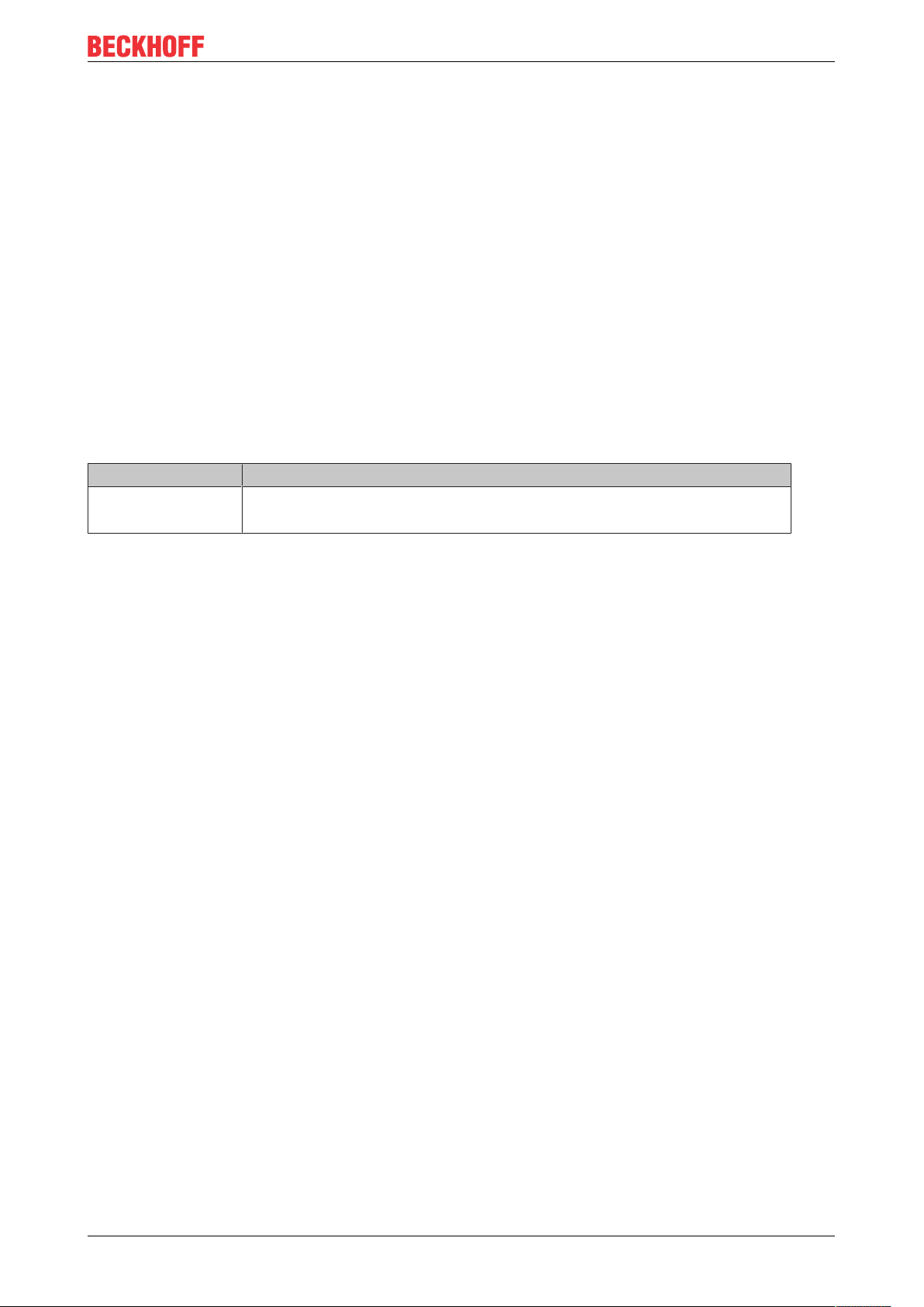
A class is represented by a three-part rectangle.
• Orange with heading <<program>>: POU (PROGRAM)
• Blue without heading: POU (FUNCTION_BLOCK or FUNCTION)
• Blue with heading <<library>>: POU (FUNCTION_BLOCK or FUNCTION) from a library (library
function block)
TF191024 Version: 2.3
Page 25
UML Class Diagram
• Greyed with heading <<missing>>: POU (FUNCTION_BLOCK or FUNCTION) from a library, which is
currently not integrated in the project
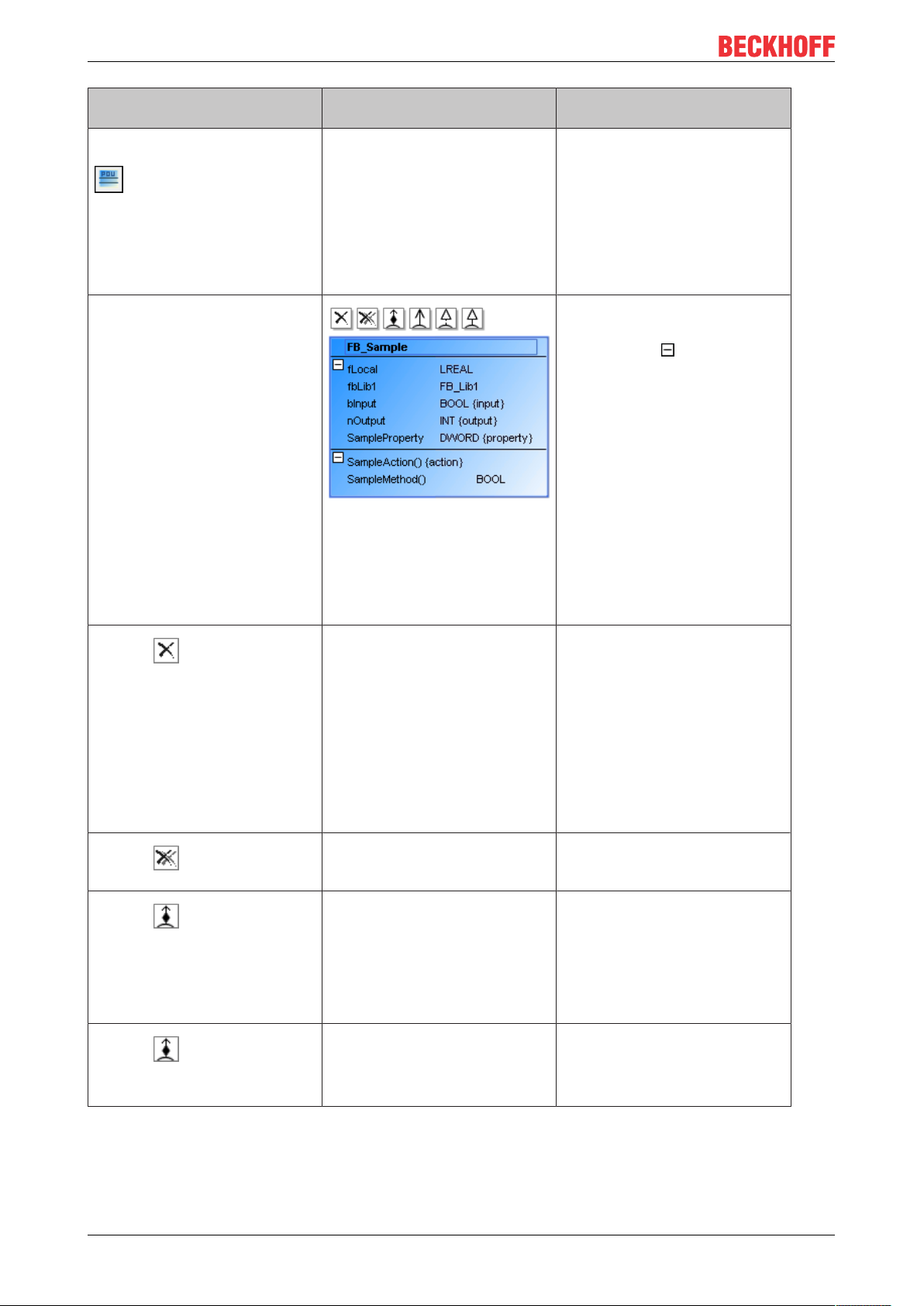
The class name follows in bold.
All attributes are shown after the first dividing line. Each visible attribute has an identifier. If {input} in curly
brackets is appended, it is a variable of type VAR_INPUT; {output} indicates a variable of type
VAR_OUTPUT. A property has the ID {property}. An internal (non-visible) variable of type VAR has no ID:
<Attribute name> : <Data type> {'{input}' | '{output}' | '{property}'}
The second dividing line is followed by all operations for the class, i.e. its methods or actions. The name of
the operation is followed by closing parentheses. This is followed by {action} to identify an action:
<action name>() {action}
If it is a method, the parentheses may indicate a variable transfer. If a return type is declared for a method,
this follows in the right-hand column. Unlike actions ({action}), methods have no concluding ID:
<Method name>(…) : <Return type>
Properties
“Property” Description
“Identifier” Class name
Sample: FB_EventLogger
User inputs for a class
The following user inputs are available if “Pointer” is enabled in the toolbox (default).
TF1910 25Version: 2.3
Page 26
UML Class Diagram
User input in the class diagram
Select the tool “Class (POU)”:
Click in an empty area of the
diagram. The dialog “Add POU”
opens. Enter a name for the new
object, adjust the settings and
close the dialog with "Add".
Select a class. The class has expanded attribute
Click on .
Click on .
Click on and then in an
empty area of the diagram. The
dialog “Add POU” opens. Enter a
name for the new object, adjust
the settings and close the dialog
with "Add".
Click on , then on an
existing class.
Response in the class diagram Description
A class is created. The object exists in the diagram
and in the project. The view in
the project tree is updated
automatically.
and operation lists, which are
identified with .
Command icons for adding
relationship elements are now
visible to the left above the class.
Tip: If the class has relationships
that are currently not shown in
the class diagram (missing
rectangular elements), a list of
“Incoming cross-references” and/
or “Outgoing cross-references”
appears in the "Toolbox" view.
Below this the missing
rectangular elements are listed,
which you can drag & drop into
the class diagram for display.
The class is removed in the
diagram, so that it is no longer
displayed.
The class is removed from the
diagram and the project.
A composition arrow points from
the existing class to the new
class.
A composition arrow points from
the first class to the second
class.
Use "flat" removal of a class to
remove it from the class diagram
view only. The object still exists
and is visible in the project tree.
Tip: The class is shown in
“Toolbox” under “Incoming crossreferences” and/or “Outgoing
cross-references”, if a rectangle
element with a relationship to the
remote element is selected in the
class diagram.
The object no longer appears as
object in the class diagram or the
project tree. It no longer exists.
The existing class contains an
instance pointing to the new
class. Sample:
fbNew : FB_New;
The first class contains an
instance pointing to the second
class. Sample:
fbExistent : FB_Existent;
TF191026 Version: 2.3
Page 27
UML Class Diagram
User input in the class diagram
Click on and then in an
empty area of the diagram. The
dialog “Add POU” opens. Enter a
name for the new object, adjust
the settings and close the dialog
with "Add".
Click on , then on an
existing class.
Click on and then in an
empty area of the diagram. The
dialog “Add POU” opens. Enter a
name, adjust the settings and
close the dialog with "Add".
Click on , then on an
existing class.
Click on and then in an
empty area of the diagram. The
dialog “Add interface” opens.
Enter an interface name, adjust
the settings and close the dialog
with "Add".
Click on , then on an
interface.
Click on .
Response in the class diagram Description
A new class with an association
arrow pointing to the existing
class is created in the diagram.
An association arrow points from
the second class to the first
class.
A generalization points from the
existing class to the new class.
The existing class inherits from
the new class.
A generalization points from the
first class to second class.
A realization arrow points from
the class to the new interface.
A realization arrow points from
the class to the interface.
A new class FB_New is created.
The existing class now knows
the new class and contains an
association with the new class.
Sample:
pNew : POINTER TO FB_New .
The first class knows the second
class. It now contains a new
variable of type. Sample:
pExistent : POINTER TO
FB_Existent;
The existing class contains the
declaration. Sample:
FUNCTION_BLOCK FB_Sub
EXTENDS FB_New
The first class contains the
declaration. Sample:
FUNCTION_BLOCK FB_Sub
EXTENDS FB_Existent
The class implements the new
interface. The declaration section
of the class contains. Sample:
FUNCTION_BLOCK FB_Sample
IMPLEMENTS I_SampleNew
The class now implements the
interface. The declaration section
of the class contains. Sample:
FUNCTION_BLOCK FB_Sample
IMPLEMENTS I_SampleExistent
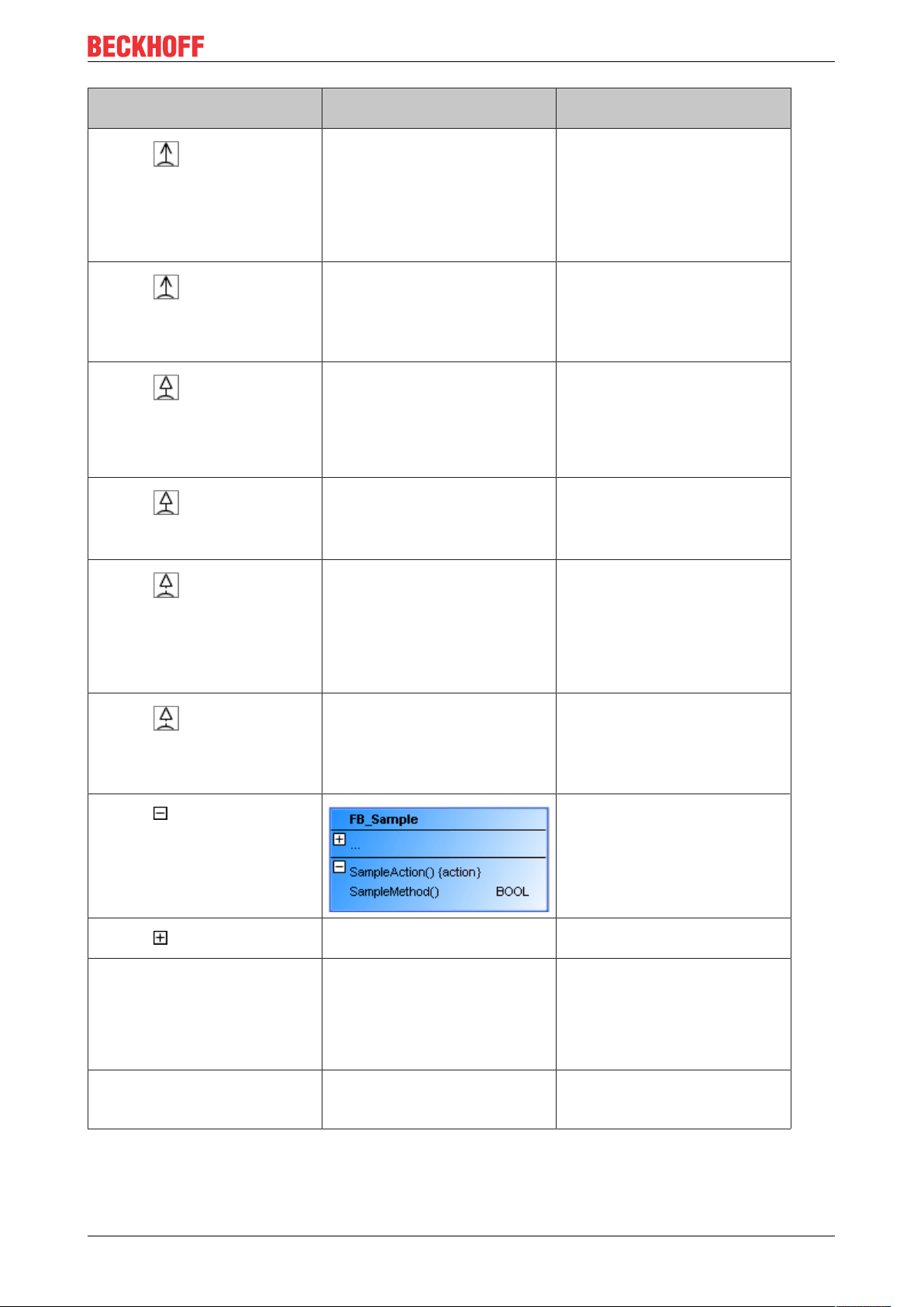
The attribute or operation list is
minimized.
Click on .
Click on the class name. Once it
is selected, click on it once
again.
Click twice on an attribute or
operation name. Then change
the name in the line editor.
TF1910 27Version: 2.3
After the first click, the name has
a blue border. After the second
click the line editor opens.
After the first click, the name has
a blue border. After the second
click the line editor opens.
The attribute or operation list
expands.
The change is applied
synchronously and automatically
to the project. That is, the object
name in the project tree and in
the declaration section of the
POU is adjusted immediately.
The change is applied
synchronously and automatically
to the project.
Page 28
UML Class Diagram
User input in the class diagram
Double-click on the class
element.
Keep in mind that the default settings in the dialog 'Add POU' or 'Add interface' originate from the
last application of this dialog.
Samples
• Composition
Response in the class diagram Description
The corresponding object editor
opens, and the declaration and
implementation are displayed.
You can change the declaration
or the implementation. After
closing of the object you are
returned to class diagram. The
changes are automatically
applied to the class diagram.
PROGRAM Test
VAR
fbSample : FB_Sample;
aSample : ARRAY[1..10] OF FB_Sample;
END_VAR
• Association
TF191028 Version: 2.3
Page 29
PROGRAM Test
VAR
pSample: POINTER TO FB_Sample;
aSample: ARRAY[1..10] OF POINTER TO FB_Sample;
END_VAR
• Generalization
UML Class Diagram
FUNCTION_BLOCKFB_SubEXTENDSFB_Base
• Implementation
TF1910 29Version: 2.3
Page 30

UML Class Diagram
INTERFACE I_Cylinder EXTENDS I_Base
FUNCTION_BLOCK FB_Cylinder IMPLEMENTS I_Cylinder
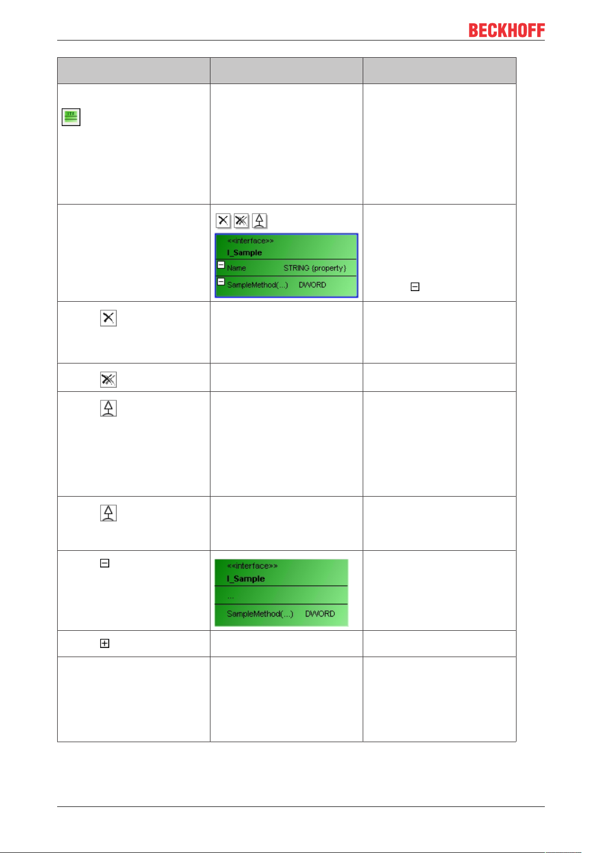
6.4.2 Interface
An interface defines methods and property declarations that describe an externally visible behavior. It
contains no variables and no implementation, but only the definition of methods and/or properties. An
interface is a variable type that can be instantiated.
An interface can have the following relationship type:
• Generalization: An interface can inherit from another interface.
Like classes, interfaces are shown divided into three parts. The rectangle is green and overwritten with
<<interface>>. The interface name follows below in bold. The interface properties are displayed after the first
dividing line, based on the following syntax:
<property name>: <data type> {property}
All interface methods follow after the second dividing line. After the method name there may be a reference
to the variable transfer in parentheses. If a return type is declared for a method, this follows in the right-hand
column.
<method name>(…): <return type>
Properties
“Property” Description
“Identifier” Insert here an unique name for the selected element. The name can be modified here,
however also within the class diagram by selecting the name and then opening an inline
editor by a further mouse click.
TF191030 Version: 2.3
Page 31

Edit interface
The following user inputs are available if “Selection” is enabled in "Toolbox" (default).
UML Class Diagram
TF1910 31Version: 2.3
Page 32
UML Class Diagram
User input in the class diagram
Select the tool "Interface":
Click in an empty area of the
diagram. The dialog “Add
interface” opens. Enter a name
for the new object, adjust the
settings and close the dialog with
"Add".
Click on an interface icon. To the left above the interface,
Click on .
Click on .
Click on and then in an
empty area of the diagram. The
dialog “Add interface” opens.
Enter a name and exit the dialog
with "Add".
Click on , then on an
existing interface.
Click on .
Response in the class diagram Description
An interface is created. The object exists in the diagram
and in the project. The view in
the project tree is updated
automatically.
icons are now visible, which
make it possible to add
relationship elements. The
example on the left has
expanded property and method
lists after .
The interface is only removed
from the diagram.
The interface is removed from
the diagram and the project.
A generalization points from the
existing interface outward to the
new interface. The existing
interface inherits from the new
interface.
A generalization points from the
second interface to the first
interface.
Use "flat" removal of an interface
to remove it from the class
diagram view only. The object
still exists and is visible in the
project tree.
The object is removed. It then no
longer exists.
The existing interface contains
the declaration. Example:
INTERFACE I_Sample
EXTENDS I_New
Keep in mind that the default
settings in the dialog 'Add
interface' originate from the last
application of this dialog.
The first interface contains the
declaration. Example:
INTERFACE I_Sample
EXTENDS I_Existent
The property or method list is
minimized.
Click on .
Click on the name. Once it is
selected, click on it once again.
After the first click, the name has
a blue border. After the second
click the line editor opens.
The property or method list is
expanded.
Change the interface name in the
line editor. The change is applied
synchronously and automatically
to the project. That is, the object
name in the project tree and in
the declaration section of the
POU is adjusted immediately.
TF191032 Version: 2.3
Page 33

UML Class Diagram
User input in the class diagram
Double-click on an interface. The corresponding object editor
Example
• Generalization
Response in the class diagram Description
opens with the declaration editor.
Edit the declaration. After closing
of the object you are returned to
class diagram. The changes are
automatically applied to the class
diagram.
INTERFACE I_Cylinder EXTENDS I_Base
6.4.3 Global Variable List
A global variable list (GVL) is used to declare global variables. These are available project-wide.
A GVL can have the following relationship types:
• Composition: a class can contain other program elements.
• Association: a class can know other program elements.
A global variable list is represented by a two-part rectangle in pale pink and headed with <<global>>. All
attributes are shown after the first dividing line:
<attribute name>: <data type>
Properties
“Property” Description
“Identifier” Insert or change an unique name of the selected element.
Edit GVL
The following user inputs are available if “Selection” is enabled in the toolbox (default).
TF1910 33Version: 2.3
Page 34

UML Class Diagram
User input in the class diagram
Select the tool "Global Variable
List (GVL)":
Click in an empty area of the
diagram. The dialog "Add Global
Variables List" opens. Enter a
name for the new object and
close the dialog with "Add".
Click on a GVL object. Command icons are visible to the
Click on .
Click on .
Click on , then on an
existing class or a DUT.
Click on and then in an
empty area of the diagram.
Dialog “Add POU” opens. Enter a
name and exit the dialog with
"Add".
Click on , then on an
existing class or a DUT.
Click on and then in an
empty area of the diagram.
The dialog “Add POU” opens.
Enter a name and exit the dialog
with "Add".
Click on .
Click on .
Click on an identifier. Once it is
selected, click again.
Response in the class diagram Description
A GVL is created. The object exists in the diagram
and in the project. The view in
the project tree is updated
automatically.
left above the object.
GVL is only removed from the
diagram.
GVL is removed from the
diagram and the project.
A composition points from the
GVL to the selected class or
DUT.
A composition points from the
GVL to the new class.
An association points from the
GVL to the selected class or
DUT.
An association points from the
GVL to the new class.
After the first click, the name has
a blue border. After the second
click the line editor opens.
Use "flat" removal to remove it
from the class diagram view only.
The object still exists and is
visible in the project tree.
The object is removed. It then no
longer exists.
The declaration of GVL contains
the instantiation based on the
selected element. Example:
fbExistent : FB_Existent;
The GVL contains the
declaration. Example:
fbNew: FB_New;
The GVL contains the
declaration for the selected
element. Example:
pExistent: POINTER TO
FB_Existent;
The GVL contains the
declaration for the new class.
Example:
pNew: POINTER TO FB_New;
The attribute or operation list is
minimized.
The attribute or operation list
expands.
Change the class name in the
line editor. The change is applied
synchronously to the project.
That is, the object name in the
project tree and in the
declaration section of the POU is
adjusted immediately.
TF191034 Version: 2.3
Page 35

UML Class Diagram
User input in the class dia-
Response in the class diagram Description
gram
Double-click an element. The corresponding object editor
opens, and the declaration and
implementation are displayed.
Keep in mind that the default settings in the dialog 'Add POU' originate from the last application of
this dialog.
Sample
• Composition
Edit the declaration or
implementation. After closing of
the object you are returned to
class diagram. The changes are
automatically applied to the class
diagram.
VAR_GLOBAL
fbMessage: FB_Message;
END_VAR
6.4.4 User-defined data type
Via a user-defined data type (“Data Unit Type” = DUT) the user can define data types, e.g. in the form of
structures or enumerations.
A user-defined structure data type can have the following relationship type:
• Generalization: a structure can inherit from another structure.
A user-defined data type is represented by a two-part rectangle in pale yellow and overwritten with
<<struct>>, if it is a structure or a union. <<enum>> indicates an enumeration type. The identifier follows in
bold. All attributes are shown after the first dividing line:
<attribute name>: <data type>
TF1910 35Version: 2.3
Page 36

UML Class Diagram
Properties
“Property” Description
“Identifier” Insert or change an unique name of the selected element.
Edit DUT
The following user inputs are available if “Selection” is enabled in the toolbox (default).
TF191036 Version: 2.3
Page 37

UML Class Diagram
User input in the class diagram
Select the tool "Data Unit Type
(DUT)":
Click in an empty area of the
diagram. The dialog “Add DUT”
opens. Enter a name for the new
object, adjust the settings and
close the dialog with "Add".
Click on a DUT. Icons are visible to the left
Click on .
Click on .
Click on and then in an
empty area of the diagram.
The dialog “Add DUT” opens.
Enter a name for the parent
object and exit the dialog with
"Add".
Click on , then on an
existing DUT.
Click on .
Click on .
Double-click on the identifier.
Then change the name in the
line editor.
Double-click the element. The corresponding object editor
Response in the class diagram Description
A data type object is created. The object exists in the diagram
and in the project. The view in
the project tree is updated
automatically.
above.
DUT is only removed from the
diagram.
DUT is removed from the
diagram and the project.
A generalization points from the
existing DUT to the new DUT.
The existing DUT inherits from
the new one.
A generalization arrow points
from the second DUT to the first
DUT.
After the first click, the name has
a blue border. After the second
click the line editor opens.
opens.
Use "flat" removal to remove it
from the class diagram view only.
The object still exists and is
visible in the project tree.
The object is removed. It then no
longer exists.
The existing DUT contains the
declaration. Example:
TYPE ST_Sample EXTENDS
ST_New
The first DUT inherits from the
second DUT. The first DUT
contains the declaration.
Example:
TYPE ST_Sample EXTENDS
ST_Existent
The attribute or operation list is
minimized.
The attribute or operation list
expands.
The change is applied
synchronously and automatically
to the project.
Edit the declaration or
implementation. After closing of
the editor you are returned to
class diagram. The changes are
automatically applied to the class
diagram.
The default settings in the dialog “Add DUT” originate from the last application of this dialog.
TF1910 37Version: 2.3
Page 38

UML Class Diagram
Sample
• Generalization
TYPE ST_Sub EXTENDS ST_Sample :
STRUCT
aMessages : ARRAY[1..10] OF STRING;
END_STRUCT
END_TYPE
6.4.5 Variable declaration
A “Variable declaration” is used for adding a variable to a class (program, function block, function) or data
structure (DUT) in the class diagram.
Add Variable
In the “Toolbox” click on “Variable declaration”:
Then select an element in the diagram for extending by a variable. If you try to select a non-reasonable
position, the cursor will look like a prohibition sign. At reasonable position it appears as a blue cross. If you
click at such a position, then the dialog “Auto declare” opens for adding a variable to the focused element.
Insert the required settings as usual. After having closed the dialog, the focused element gets extended by
the new variable. An appropriate update will be done synchronously in the class diagram and in the object
editor.
Look of the cursor
• : At this position, no adding is possible.
• : At this position, you can add a variable to the focused element.
6.4.6 Property
A property is used for extending a class (program or function block) or an interface by one.
Add property
In the “Toolbox” click on “Property”:
Then select an element in the diagram for extending by a property. If you try to select a non-reasonable
position, the cursor will look like a prohibition sign. At reasonable position it appears as a blue cross. If you
click at such a position, then the dialog “Auto declare” opens for adding a property to the focused element.
TF191038 Version: 2.3
Page 39

UML Class Diagram
Insert the required settings as usual. After having closed the dialog, the focused element gets extended by
the new property. An appropriate update will be done synchronously in the class diagram and in the object
editor.
Look of the cursor
• : At this position, no extending is possible.
• : At this position you can add a property to the focused element.
6.4.7 Method
The element "Method" is used to extend a class (program or function block) or an interface with a method.
Add method
Select the tool "Method":
In the diagram you can then select the element that is to be extended with a method. At points that are not
meaningful, the cursor has the form of a prohibition sign. At meaningful points the cursor has the form of a
blue or black cross. If you click on such a point, a further method is added to the element in focus. The dialog
“Add method” opens. Enter the required settings as usual. Closing the dialog expands the program element
with this method, which is immediately updated in the class diagram and in the project tree.
Cursor
• : at these points in the diagram expansion is not possible.
• : at these points in the diagram, you can expand the element in focus with a method.
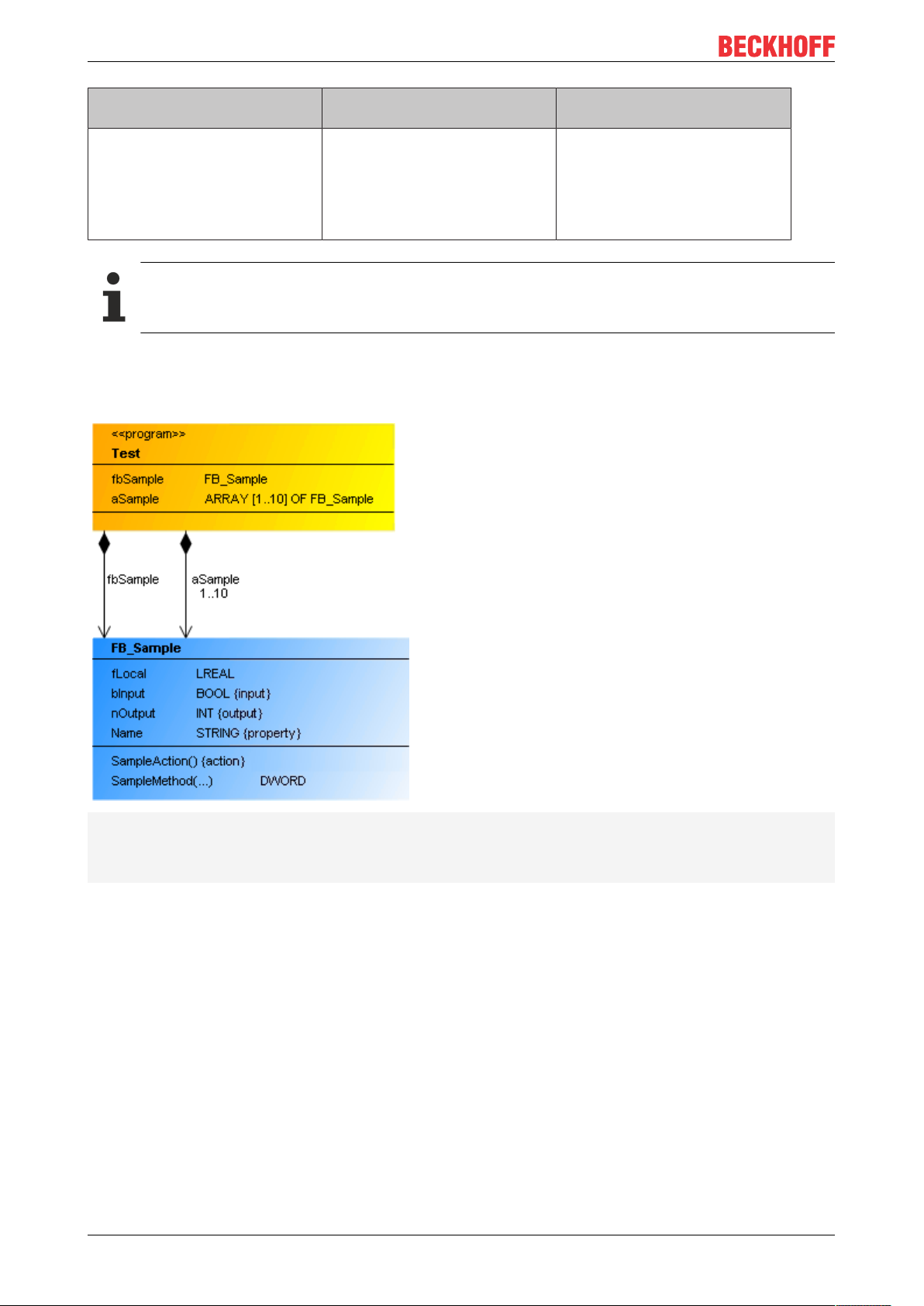
6.4.8 Composition
A composition is a UML relationship that expresses a "contained" property: an element contains another
element. In IEC code, this corresponds to the instantiation of an element: fbSample: FB_Sample. The
cardinality indicates how often the relationship exists. In IEC code this corresponds to an ARRAY [...]. If a
cardinality greater than 1 is specified, the declaration is as follow: aSample: ARRAY[1..10] OF FB_Sample.
A composition is represented as an arrow with a solid black diamond, pointing from a class or a global
variable list to a class of type FUNCTION_BLOCK or a DUT.
TF1910 39Version: 2.3
Page 40

UML Class Diagram
Property
“Property” Description
“Relationship” Composition (not editable)
“Optimize route” If the option is enabled, the route of the relationship arrow is optimized
automatically. The starting point at the start element and the end point at the
target element are fixed. If, for sample, the target element is moved, the point
to which the arrow points on the target element is retained. If the option is
disabled, the route is retained. This option is deselected when a relationship
element is positioned manually in the class diagram.
Activate the option if automatic optimization is required.
“Start element” The name of the element at which the relationship element starts is displayed.
“Target element” The name of the element to which the relationship element points is displayed.
“Identifier” The name of the relationship element is displayed.
Edit composition
User input in the class diagram
Select the tool "Composition":
Select a class or a GVL, then
click on the element to include.
Select the tool "Composition":
Select a class or a GVL, then
click in an empty area of the
diagram. The dialog “Add POU”
opens. Enter a name, adjust the
settings and close the dialog with
"Add".
Select the tool "Pointer“.
Click on a composition and move
the line with the mouse.
Select the tool "Pointer“.
Click on a composition and use
the [Del] key or click on "Delete"
in the context menu.
Response in the class diagram Description
A composition between the
elements is drawn.
A composition pointing from the
class or GVL to the new class is
created.
The IEC code is automatically
adapted by extending the
declaration section of the existing
element. Example:
fbExistent: FB_Existent;
The IEC code is automatically
adapted by extending the
declaration section of the existing
element. Example:
fbNew: FB_New;
The selected (and therefore blue)
composition runs at the new
position. The property "Optimize
routing" is automatically
disabled.
The association is removed from
diagram and the IEC code. The
instantiation of the class or the
data type is removed from the
declaration section of the
element.
Samples
• Composition of a class
TF191040 Version: 2.3
Page 41

• Single composition
PROGRAM Test
VAR
fbSample : FB_Sample;
END_VAR
• Multiple composition
PROGRAM Test
VAR
aSample : ARRAY[1..10] OF FB_Sample;
END_VAR
• Composition of a data object
UML Class Diagram
FUNCTION_BLOCK FB_Message
VAR_INPUT
stMessageStation1 : ST_Message;
END_VAR
• Composition in GVL
TF1910 41Version: 2.3
Page 42

UML Class Diagram
VAR_GLOBAL
fbMessage: FB_Message;
END_VAR
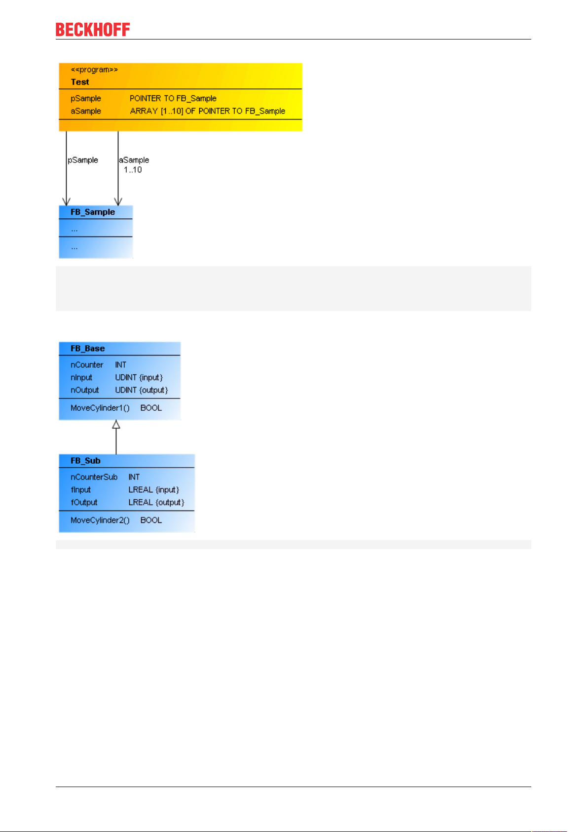
6.4.9 Association
An association is a UML relationship that expresses "knowing". The knowing element points as a pointer or
reference to another element. In IEC code this corresponds to a POINTER TO instruction (pSample :
POINTER TO FB_Sample) or a REFERENCE TO instruction (refSample : REFERENCE TO FB_Sample).
In the case of pointers, the cardinality specifies how often the relationship exists. In IEC code this
corresponds to an ARRAY [...]. If a cardinality greater than 1 is specified, the declaration is as follow:
aSample : ARRAY[1..10] OF POINTER TO FB_Sample.
An association is represented as an arrow pointing from a class or a global variable list to a class of type
FUNCTION_BLOCK or DUT.
TF191042 Version: 2.3
Page 43

UML Class Diagram
Property
“Property” Description
“Relationship” Association (cannot be edited)
“Optimize route” If the option is enabled, the route of the relationship arrow is optimized
automatically. The starting point at the start element and the end point at the
target element are fixed. If, for sample, the target element is moved, the point
to which the arrow points on the target element is retained. If the option is
disabled, the route is retained. This option is deselected when a relationship
element is positioned manually in the class diagram.
Activate the option if automatic optimization is required.
“Start element” The name of the element at which the relationship element starts is displayed.
“Target element” The name of the element to which the relationship element points is displayed.
“Identifier” The name of the relationship element is displayed.
Edit association
User input in the class diagram
Select the tool "Association":
Select a class or a GVL, then
click on the object to be used for
the association.
Select the tool "Association":
Select a class or a GVL, then
click in an empty area of the
diagram.
The dialog "Add POU" opens.
Enter a name, adjust the settings
and close the dialog with "Add".
Select the tool "Pointer".
Click on an association and
move the line with the mouse.
Select the tool "Pointer".
Click on an association and use
the [Del] key or click on "Delete"
in the context menu.
Response in the class diagram Description
An association between the
elements is drawn.
An association pointing from the
class or GVL to the new class is
created.
The IEC code is automatically
adapted by extending the
declaration part of the existing
element. Example:
pExistent : POINTER TO
FB_Existent;
The IEC code is automatically
adapted by extending the
declaration part of the existing
element. Example:
pNew : POINTER TO FB_New;
The selected (and therefore blue)
association runs at the new
position. The property "Optimize
routing" is automatically
disabled.
The association is removed from
diagram and the IEC code. The
POINTER TO or REFERENCE
TO instruction is removed from
the declaration part of the
element.
Samples
• Association with a class (of a program) – single and multiple
TF1910 43Version: 2.3
Page 44

UML Class Diagram
PROGRAM Test
VAR
pSample: POINTER TO FB_Sample;
aSample: ARRAY[1..10] OF POINTER TO FB_Sample;
END_VAR
• Association with a data structure (of a GVL) – single
VAR_GLOBAL
pMessage: POINTER TO ST_Message;
END_VAR
6.4.10 Implementation
A realization is a UML relationship that expresses an interface implementation. The realizing or implementing
class object (function block) implements the properties and methods of the interface. In IEC coding this
relationship corresponds to the keyword IMPLEMENTS.
A realization is indicated by a dashed arrow, pointing from a class of type FUNCTION_BLOCK to an
interface.
TF191044 Version: 2.3
Page 45

Property
“Property” Description
“Relationship” Realization (not editable)
Edit realization
UML Class Diagram
User input in the class diagram
Select the tool "Realization":
Select a class and then an
interface.
Select the tool "Realization":
Select a class, then click in an
empty area of the diagram.
The dialog “Add interface” opens.
Enter a name, adjust the settings
and close the dialog with "Add".
Select the tool "Pointer“.
Click on a realization and move
the line with the mouse.
Select the tool "Pointer“.
Click on a realization and use the
[Del] key or click on "Delete" in
the context menu.
Response in the class diagram Description
A realization is created, pointing
from the class to the interface.
The IEC code is automatically
adapted to indicate the interface
in the declaration section of the
class. Example:
FUNCTION_BLOCK FB_Sample
IMPLEMENTS I_Existent
A realization is created, pointing
from the class to the new
interface.
The IEC code is automatically
adapted by creating a new
interface and indicating this
interface in the declaration
section of the class. Example:
FUNCTION_BLOCK FB_Sample
IMPLEMENTS I_New
The selected (and therefore blue)
realization runs at the new
position.
The realization is removed from
diagram and the IEC code. The
IMPLEMENTS statement is
removed from the declaration
section of the class.
Example
• Realization
INTERFACE I_Cylinder EXTENDS I_Base
FUNCTION_BLOCK FB_Cylinder IMPLEMENTS I_Cylinder
TF1910 45Version: 2.3
Page 46

UML Class Diagram
6.4.11 Generalization
A generalization is a UML relationship that expresses an inheritance or specialization. The inheriting element
has the attributes and operations of the element from which it inherits. In IEC coding this relationship
corresponds to the keyword EXTENDS.
A generalization indicated by an arrow with a solid tip, pointing from the inheriting class to the base class
from which it inherits. The direction of the arrow indicates which component inherits from which.
Inheritance is possible between classes, interfaces and user-defined data types:
• A function block can inherit from another function block.
• An interface can inherit from another interface.
• A DUT can inherit from another DUT.
• Programs and functions cannot inherit or pass on.
Property
“Property” Description
“Relationship” Generalization (not editable)
TF191046 Version: 2.3
Page 47

Edit generalization
UML Class Diagram
User input in the class diagram
Select the tool “Generalization”:
Select the object that is to inherit,
then click on the parent object.
Select the tool “Generalization”:
Select the object that is to inherit,
and then click on an empty area
in the diagram.
A dialog for creating a new object
opens. Enter a name, adjust the
settings and close the dialog with
"Add".
Select the tool "Pointer“.
Click on a generalization and
move the line with the mouse.
Select the tool "Pointer“.
Click on a realization and use the
[Del] key or click on "Delete" in
the context menu.
Response in the class diagram Description
A generalization is created,
pointing from the inheriting
element to the parent element.
The IEC code is automatically
adapted to indicate the parent
element in the declaration
section of the inheriting class.
Example:
FUNCTION_BLOCK FB_Sample
EXTENDS FB_BaseExistent
A generalization is created,
pointing from the inheriting
element to the new parent
element.
The IEC code is automatically
adapted by creating a new object
and indicating the parent object
in the declaration section of the
inheriting object. Example:
FUNCTION_BLOCK FB_Sample
EXTENDS FB_BaseNew
The selected (and therefore blue)
generalization runs at the new
position.
The generalization is removed
from the diagram and the IEC
code. The EXTENDS statement
is removed from the declaration
section of the inheriting object
Samples
• Function block
FUNCTION_BLOCKFB_SubEXTENDSFB_Base
• Interface
TF1910 47Version: 2.3
Page 48

UML Class Diagram
INTERFACEI_CylinderEXTENDSI_Base
• DUT
TYPE ST_Sub EXTENDS ST_Sample :
STRUCT
aMessages : ARRAY[1..10] OF STRING;
END_STRUCT
END_TYPE
TF191048 Version: 2.3
Page 49

UML state diagram
7 UML state diagram
In addition to the following information, please refer to the samples [}88], which provide an introduction to
the tool and to the call behavior of the UML state diagram.
7.1 Basic principles
The UML statechart is a graphical formalism for specifying and designing the sequence of a discrete-event
system, resp. for programming time behavior. Integrated in the TwinCAT 3 Development System, a
statechart has an editor with state elements and transition elements. When compiling the application,
executable code is generated. The transition behavior of a statechart during executing depends on the task
cycle. But it can switch independed as well. Then, it is an in-cycle. Powerful tools, including tools for syntax
control or debugging in online mode support the development process.
Application case
A Statechart is used for programming time-discrete systems. Programs, function blocks, functions, methods
or actions can be created as a graph from states and transitions with the Statechart implementation
language.
Functions/methods and their data are normally temporary. If you implement a function/method with the UML
Statechart implementation language, the chart contains cycle-internal states and re-initializes the data at the
start of the task cycle.
With methods, conversely, there is a possibility to declare the method as VAR_INST. The data are then
retained as with a function block and are not temporary, therefore the Statechart will be run through in
several task cycles as usual. Refer also to Option UseVarInst [}81] regarding this. This option is not
available with functions.
Syntax
The syntax is under compiler control:
• a transition between states lying in different regions are not allowed
• orthogonal states cannot be nested in other states
• exactly one exception transition or completion transition is allowed to exit a composite state
• a conditional transition going into an orthogonal state is not allowed, then a fork/join is required
Commands
The following commands or action options are available for the Statechart:
• Creating a new Statechart [}51]
• Editing Statechart [}52]
• Go to Definition [}56]
Also note the commands, which are available for all UML diagrams: Common commands for all UML
diagrams. [}13]
Implicit variables of a state diagram
The implicit variables are located in the program unit that maps the state diagram (e.g. in the instance of the
function block or in a program). The internal variables are located inside the program unit under the element
name "UML_SC_<POU name>" with the data type "UML_SC_<id>".
For the function block "FB_UML", the element name of the implicit variables is "UML_SC_FB_UML", for
example. They are located in the function block instance "fbUml".
TF1910 49Version: 2.3
Page 50

UML state diagram
"UML_SC_<POU name>" of the data type _UML_SC_<id>:
Some implicit variables reflect the state of the object during the runtime (InFinalState, States), while others
serve to control the behavior at runtime (Reinit, Abort, AutoReInit).
Name Data type Meaning
InFinalState BOOL This variable has the value TRUE if the
state diagram is in the end state.
ReInit BOOL Setting this variable to TRUE will cause the
state diagram to be re-initialized, i.e. the
start state of the diagram is activated.
Abort BOOL Setting this variable to TRUE will cause the
current operation of the diagram to be
aborted and the end state of the diagram to
be activated.
AutoReInit BOOL If the value of this variable is TRUE, the
start state of the diagram is automatically
restored as soon as the end state is
reached.
Default value: TRUE
States ARRAY[<number of states>]
OF _UML_SC_State
Names _UML_SC_<id>_Names See below
See below
"UML_SC_<POU name>.States" of the data type ARRAY[<number of states>] OF _UML_SC_State:
The variables of the structure _UML_SC_State serve to describe a state. This data type is the base type of
an array with the name "States", which is declared in the implicit variables and describes the individual states
of the state diagram.
The individual variables of the structure _UML_SC_State are described in the following table.
TF191050 Version: 2.3
Page 51

UML state diagram
Name Data type Meaning
Active BOOL Flag for determining whether the state is
currently active.
FastExecutionFault BOOL Relevant for IntraCycle states: If an
IntraCycle state is active for longer than a
cycle, this flag is set by the system. The
flag is reset on exiting from the IntraCycle
state.
ID INT ID of the state
The ID of the state corresponds to the
index at which the state is described in the
"States" array.
ActivationTime TIME Timestamp of the last activation of the
state
Name STRING Name of the state
"UML_SC_<POU name>.Names" of the data type _UML_SC_<id>_Names:
The data type _UML_SC_<id>_Names contains an INT variable for each state of the state diagram. This
variable is declared with the name of the state and its value indicates the ID of the state. The ID of the state
corresponds to the index at which the state is described in the "States" array.
Name Data type Meaning
<Name of the state>
Sample: StartState1
<Name of the state>
Sample: State1
<Name of the state>
Sample: State2
… … …
INT ID of the state (= index at which the state is
described in the "States" array)
Sample: ID of the state "StartState1", e.g.
4
INT ID of the state (= index at which the state is
described in the "States" array)
Sample: ID of the state "State1", e.g. 5
INT ID of the state (= index at which the state is
described in the "States" array)
Sample: ID of the state "State2", e.g. 6
7.2 Commands
7.2.1 Creating a new Statechart
Programs, function blocks, functions, methods or actions can be created as a graph from states and
transitions with the Statechart implementation language.
1. In the context menu of the project tree select the command for adding the required program element
(e.g. function block, method).
TF1910 51Version: 2.3
Page 52

UML state diagram
2. Configure the opening dialog as usual (for a POU element, e.g. name and type) and select UML
Statechart (SC) as the implementation language.
3. Confirm the inputs and configurations with the Open button.
ð The new statechart object is added in the project tree, and the editor for the new diagrams opens.
7.2.2 Editing Statechart
The actions available for editing a Statechart include the following. Further editing options can be found
under e [}56]ditor.
Adding a new element
1. Open the Toolbox window via the View menu.
2. Select an element [}57] in the Toolbox view and drag & drop it onto the opened Statechart. Drop it in a
suitable location to visualize it there.
ð The new element is shown in the diagram.
Deselect “Toolbox” view
ü An element is selected in the Toolbox window. In the editor the cursor has the form of the selected ele-
ment.
1. Press the right mouse button.
TF191052 Version: 2.3
Page 53

UML state diagram
ð The element is deselected, and the standard Pointer element is selected.
Editing identifiers
1. Open the line editor of an identifier with two single clicks.
2. Enter a new name and confirm it via the [Enter] key or by clicking in an empty area of the diagram.
ð The identifier has the new name.
Adding a new action object
1. Click on the symbol New <ENTRY/DO/EXIT> action/method, which appears at the end of an action line
for a state and at the start of an action line for a composite state.
Requirement: So far the action line has no declaration or implementation.
ð The dialog New action object opens.
2. Specify the object type in the left part of the dialog by selecting Action or Method.
3. If the object type Action is selected: Configure the name and the implementation language for the new
action.
If the object type Method is selected: Configure the name, the return type, the implementation language
TF1910 53Version: 2.3
Page 54

UML state diagram
and the access modifier for the new method.
4. Confirm the inputs and configurations with the Add button.
ð The new action or method object is added to the project tree and displayed as linked object in the edited
state. In addition, the editor for the new action or the new method opens.
Creating a new transition
Transitions can be created based on various source elements: start state, state, composite state, choice,
fork/join.
The possible target elements, for which an incoming transition is created, depend on the source element
type and the transition type (transition, completion transition, exception transition).
The general procedure for generating a transition is explained below.
Option 1 – via icon:
1. Select an element in the opened Statechart.
2. Click on a transition icon, which appears above the element (the selected element acts as source
element).
3. Click on an existing element to configure it as target element for the selected transition. Alternatively,
click in a blank area of the editor to generate a new state.
TF191054 Version: 2.3
Page 55

UML state diagram
4. Configure the action and the guard condition for the transition as required by opening the respective line
editors with two single clicks. If the guard condition depends on more than one variable, you can insert a
new line via [Ctrl+Enter] during the configuration of the transition condition, in order to show the whole
transition more clearly.
ð You have created a transition from source to target element, which determines the switching
characteristics of the Statechart.
Option 2 – via Toolbox:
1. Click on a transition element from Toolbox.
2. In the open Statechart first click on the source element, then on an existing element in order to configure
it as target element for the selected transition. Alternatively, click in a blank area of the editor to generate
a new state.
3. Configure the action and the guard condition for the transition as required by opening the respective line
editors with two single clicks. If the guard condition depends on more than one variable, you can insert a
new line via [Ctrl+Enter] during the configuration of the transition condition, in order to show the whole
transition more clearly.
ð You have created a transition from source to target element, which determines the switching
characteristics of the Statechart.
Changing the end points of an existing transition
The end points of an existing transition can be linked to other source or target elements using the Reconnect
functionality. As a result, existing transition configurations (action, guard condition) are retained, while the
transition connections change.
1. Click on the start or the end of a transition, depending on whether you want to change the source
element or the target element.
ð The reconnect symbol appears at the transition connection.
2. Drag & drop the symbol onto another source or target element to connect the transition there.
ð The transition was linked to another source/target element, without changing the other transition
configurations.
As project navigator
1. Open a Statechart and double-click on an action object of a (composite) state.
ð The editor for the action object opens.
2. If required, you can change the declaration and implementation of the action object in the open editor.
ð Use the project navigator functionality to view or adjust the behavior of the selected action object.
Multiple selections
• If Pointer is enabled in Toolbox (default), you can drag a rectangle over several elements in the
Statechart while pressing the left mouse button. All elements covered by the rectangle are then
selected.
TF1910 55Version: 2.3
Page 56

UML state diagram
• Multiple selections are also possible by successively selecting the required elements while pressing the
[Ctrl] key.
• Use [Ctrl+A] or Select all to select all elements of the diagram.
7.2.3 Go to definition
For transitions, the command Go To Definition is available in the corresponding context menu.
The command is available in offline and online mode.
1. Right-click on a transition to open the corresponding context menu.
2. Select the command Go to Definition.
ð The editor, in which the first variable of the transition or the transition expression is declared, opens and
the variable is marked in the declaration editor.
7.2.4 Find All References
For transitions, the command Find All References is available in the corresponding context menu.
The command is available in offline and online mode.
1. Right-click on a transition to open the corresponding context menu.
2. Select the command Find All References.
ð The Cross Reference List view opens and shows the locations where the first variables of the transition
or transition expression are used.
7.2.5 Add Watch
For transitions, the command Add Watch is available in the corresponding context menu.
The command is only available in online mode and provides a further debugging option – in addition to the
integrated online view available with the transition – for transferring the variables of a transition to the watch
list via a command. This command is particularly useful if a transition expression consists of a combination of
several variables (e.g. "bCondition1 AND bCondition2"). If you execute the command Add Watch for this
transition, both variables of the transition expression are added to the watch list, i.e. bCondition1 and
bCondition2. This gives you a simple overview of which sub-signal of the overall expression does not yet
have the required value for switching to the next state.
1. Right-click on a transition to open the corresponding context menu. The transition expression can consist
of one or more variables.
2. Select the Add Watch command.
ð The transition expression variable(s) is/are inserted in the currently open watch list. If no watch list is
currently open, the command inserts the variable(s) into Watch List 1 and opens its view.
7.3 Editor
The Statechart editor is used for designing and programming procedures based on a Statechart. The state is
the main element of the Statechart. A Statechart is usually clocked via the task cycle, although cycle-internal
state machines are also possible (see configuration of a state [}58]).
The Statechart can be edited through various actions. The editing options are documented here [}52].
In addition, there are further, element-specific user inputs:
• Edit state [}60]
• Edit transition [}77]
TF191056 Version: 2.3
Page 57

UML state diagram
• Edit completion transition [}78]
• Edit exception transition [}81]
• Edit start state [}58]
• Edit choice [}75]
• Edit composite state [}65]
• Edit fork/join [}73]
7.4 Elements
The Tools window shows the elements of the state diagram. They can be added to the State diagram
window via drag & drop. States and pseudo states can be positioned as required.
Insert element
1. Open View > Tools to access the elements.
2. Drag an element into the State diagram window and drop it at a suitable location.
Start state [}57]
End state [}58]
State [}58]
Composite state [}62]
Fork/Join [}72]
Choice [}74]
Transition [}75]
Completion transition [}77]
Exception transition [}78]
7.4.1 Start State
A start state is a pseudo state that indicates the initial state. If it is at top-level, the sequence of the state
chart starts there. If it is in a composite states or in region of an orthogonal state, the sequence of the region
starts.
TF1910 57Version: 2.3
Page 58

UML state diagram
The start state is displayed as a black, filled circle.
Properties
“Property” Description
“Identifier” Here, you can enter a name. It will not be displayed
in the statechart.
Edit start state
User input in the Statechart Response in the State-
chart
Focus on a start state. The start state is editable.
Click on the symbol
Description
• A completion transition can be added via
the command icon that is displayed above
the start state.
A completion transition is added. If you click
on an existing state, it becomes the target
state of the transition. Click in an empty area
to create a new state.
7.4.2 End State
An End state is a pseudo state that indicates that the execution of the region containing this end state has
been completed. End states can be located in statecharts at top level, in composite states, or in regions of
orthogonal states.
An end state is displayed as a little black, filled circle within a second empty circle.
Property
„Property“ Description
„Identifier“ Here, you can enter a name. It will not be
displayed in the statechart.
7.4.3 State
A state is the main element of a state diagram. A state machine (or state diagram) passes through various
states and executes their actions during its runtime. A state can have ENTRY, DO or EXIT actions, which are
executed at specified times during the runtime of the state.
A state is displayed as a rectangle with rounded corners.
TF191058 Version: 2.3
Page 59

UML state diagram
Normal state
A normal state is clocked by the task in which it is called. This means that the transition into the next state is
not called before the next task cycle switches.
Cycle-internal state
If a state machine consists of cycle-internal states, the switching characteristics are independent of the task
cycle. This means that completion of the actions of an internal state is followed immediately by the transition.
The transition condition is checked immediately, and the transition action is executed when the condition is
met. Also, the system immediately switches to the target state when the transition condition is met.
Whether a state switches cycle-internally is set in the property “Internal state”.
ENTRY, DO, EXIT actions/methods
A state can have an ENTRY, DO and/or EXIT action or method. For these actions or methods you can
choose any implementation language.
• The ENTRY action can initialize the state. It is executed once when all incoming transitions switch, so
that the state becomes active.
• The DO action is executed as long as the state is active.
• The EXIT action is intended to ensure that the state is exited in a valid state. The EXIT action is
executed once when all outgoing transitions switch, so that the state is exited.
Call behavior
Make sure you refer to the samples [}88], which describe and illustrate the call behavior of the UML state
diagram.
TF1910 59Version: 2.3
Page 60

UML state diagram
Properties
"Property" Description
"Identifier" Name of the state
Example: Enable, Production, ErrorHandling
"Color" Color of the state
Click on the set color to change the color of the state via the dropdown menu
that opens.
Preset:
"Implicit start state" • No: [Default] Set the property to No if you require a normal state.
• Diagram: Set the property to diagram if you want that the state to be also a
start state. A state machine requires a start state at the top level and also
each region in a composite state.
"Cycle-internal"
• : Tick the checkbox to set the state cycle to internal. In "Cycle-internal"
the transition is immediately switched to the next state.
• : [Default] Untick the checkbox to set the state cycle to normal. The state
then changes with the task cycle. A transition to the next state is executed
with a cycle change of the task.
"Max. DO cycle calls" Requirement: This property is available if the property "Cycle-internal" is
activated.
Define the maximum number of calls of the DO action per cycle. Enter a number
between 1 and 32767. This setting is relevant for the cycle-internal states if the
outgoing transition of the cycle-internal state is not fulfilled during the processing
of the cycle-internal state and will also not be fulfilled during the DO calls.
Setting the maximum number of calls ensures that calling the cycle-internal
state does not lead to an infinite loop.
"ENTRY action" Assign an action to the selected state by specifying its action name.
"DO action"
"EXIT action"
Edit state
The following user inputs are available, provided “Pointer” or “Choice” is enabled in “Toolbox” (standard
mode).
TF191060 Version: 2.3
Page 61

UML state diagram
User input in the state diagram
Focus on a state. The state is editable.
Click on the symbol
Generate several transitions on
the same state.
Response in the state diagram
Description
• You can edit the name through two
single clicks on the name.
• You can add outgoing transitions via
the command icon above the state.
• Via the three icons in the center of the
state you can extend the state with an
ENTRY, DO and/or EXIT action.
• The state can be removed with the [Del]
key.
An outgoing transition is created. If you
click on an existing state, it becomes the
target state of the transition. Click in an
empty area to create a new state.
If a state has more than one outgoing/
incoming transition, the priorities of the
transitions define their execution order.
The priority of the transitions is shown in a
small circle.
Click on :
Click on :
Click on :
Focus on a state, which was
extended by an action, and
click on the symbol .
Click twice (two single clicks)
on the ENTRY, DO or EXIT
expression (irrespective of
whether an action was already
assigned or not).
The state is extended by an ENTRY
action/method.
The state is extended by a DO action/
method.
The state is extended by an EXIT action/
method.
For action lines the symbol appears at the
end of the line, if no action has been
assigned yet.
The dialog “New action object” opens for
generating a new action. The name of the
action is shown after a slash.
See also: “Add new action object” [}53]
The line editor opens with IntelliSense
support, so that a new action can be
assigned. If the required action is selected
in IntelliSense, the action can be selected
by double-clicking or single-clicking plus
[Enter].
TF1910 61Version: 2.3
Page 62

UML state diagram
User input in the state diagram
Focus on a state that was
assigned an action. Click on the
symbol or double-click on
the assigned action.
Click on :
Click on :
Response in the state diagram
Description
The assigned action, “SampleMethod” in
the sample, opens in the editor. The
action object can be edited in the POU
editor that opens.
The action list for the state collapses.
The action list for the state expands.
7.4.4 Composite State
A composite state is used for grouping the states it covers. It can be used for two different use cases:
• Grouping/Nesting:
◦ If a composite state consists of precisely one region, the inner states are passed through
sequentially at runtime. An inner state can thereby be a composite state again, so that a nesting of
composite states is created. In addition, such composite states can call ENTRY/DO/EXIT actions.
◦ Composite states, each with a particular region, are used to group states, so that shared
forwarding or shared error handling can be implemented, e.g. with the aid of (pseudo) exception
transitions. In addition or alternatively, the composite state can be provided with its own ENTRY/
DO/EXIT actions, which can be topically assigned to the inner states. This is interesting, for
example, if a higher-level DO action is to be called in addition to the DO actions of the inner states.
In this case the higher-level DO action could be placed in the composite state.
• Parallel sub-state machines:
◦ If a composite state consists of several regions, the inner states are grouped orthogonally. The
regions of the composite state are assigned priorities, which control the processing order at
runtime. The states of the regions are passed through pseudo-parallel, according to their internal
sequencing.
◦ Composite states with several regions or so-called orthogonal states are used for programming
parallel states.
Samples of the implementation of various use cases can be found at the foot of this page.
TF191062 Version: 2.3
Page 63

UML state diagram
A composite state is shown as a yellow, filled rectangle with rounded corners. Its name is displayed in the
upper left corner of the rectangle. Regions are separated by black dashed lines.
In the case of a composite state with several regions, the priority of each region is displayed in the top righthand corner and the name of each region in top left-hand corner of the region. The lines, names and
priorities are editable.
Syntax rules
General syntax rules for composite states
• A composite state can have one or several outgoing exception transitions. An error handling, for
example, can be implemented with the aid of an exception transition.
• Completion transition
◦ A composite state can only have one outgoing completion transition.
◦ If a composite state has an outgoing completion transition, each region must contain a start and
end state.
◦ The regions do not require an end state if the composite state has no outgoing completion
transition.
◦ However, the composite state must have an outgoing completion transition if all regions of the
composite state contain an end state.
◦ The composite state reaches its end state when all regions have reached their respective end
states.
TF1910 63Version: 2.3
Page 64

UML state diagram
Syntax rules for a composite state with precisely one region
• Activate start state/composite state
◦ If the composite state has an outgoing completion transition, the region must have a start and end
state (refer also to the general syntax rules regarding the end state) and the incoming transition
must be connected to the composite state to activate it.
◦ If the composite state has no outgoing completion transition, the region can optionally contain a
start state.
If a start state is present, the incoming transition must be connected to the composite state to
activate it. A direct connection via a conditional transition between a state inside the composite
state and a state outside of the composite state is not allowed – neither from the outside inwards
nor from the inside outwards.
If no start state is present, conversely, the incoming transitions will be connected directly to the
inner states. This could be one or more incoming transitions. Furthermore, the other direction is
also possible in this case: starting from the states inside the composite state, outgoing conditional
transitions can be connected directly to states outside of the composite state. This could be one or
more outgoing transitions. Please note that states inside and outside of a composite state may
only be directly connected to one another (regardless of the direction) if the inner and outer state
are separated only by one level of a composite state. This means that a state located inside a
composite state that is in turn located inside another composite state (nesting) cannot be directly
connected to a state located outside this nesting of composite states. This connection would cross
two borders of composite states, but it is only allowed to cross one border. The named state can
only be directly connected with an outside state if this target state is located in the outer composite
state (only one level crossed).
• Nesting
◦ A composite state with precisely one region can contain another composite state. In this case the
states are nested.
◦ Composite states can be nested to any depth; none of the states, including the innermost, may
have several regions.
Syntax rules for a composite state with several regions
• Activate start state/composite state
◦ The incoming transition must be linked with the composite state to activate it.
◦ Each region must contain a start state.
• Transitions between states in different regions are not permitted.
• A direct connection via a conditional transition between a state inside the composite state and a state
outside of the composite state is not allowed – neither from the outside inwards nor from the inside
outwards.
Exception: you can create transitions that go to states inside the composite state with the aid of a fork
located outside of the composite state.
ENTRY, DO, EXIT actions/methods
A composite state that has precisely one region can be assigned ENTRY/DO/EXIT actions/methods.
In order to enable this function, the option "Allow ENTRY/DO/EXIT actions" must be activated. This option is
located in the properties of the composite state. For these actions or methods you can choose any
implementation language.
• The ENTRY action can initialize the composite state. It is executed once when all incoming transitions
switch or when an internal state becomes active, so that the composite state is activated.
• Note the description of the property "Execute DO actions, even if inner composite states are active",
which determines the behavior of the DO action.
• The EXIT action is intended to ensure that the composite state is exited in a valid state. The EXIT
action is executed once when all outgoing transitions switch or when an outer state becomes active, so
that the composite state is exited.
TF191064 Version: 2.3
Page 65

UML state diagram
Call behavior
Make sure you refer to the samples [}88], which describe and illustrate the call behavior of the UML state
diagram.
Properties
"Property" Description
"Identifier" Name of the composite state
Example: DoorAutomation
"Color" Color of the composite state
Click on the set color to change the color of the composite state via the
dropdown menu that opens.
Preset:
"Allow ENTRY/DO/EXIT
actions"
Requirement: This property is available when the selected composite state has
exactly one region. In this case you can also assign actions to a composite state
if it is part of a nesting of composite states.
: You can assign an ENTRY, DO or EXIT action to the selected composite
state.
: You cannot assign ENTRY, DO or EXIT actions to the selected composite
state.
"Execute DO actions, even
if inner composite states
are active"
"ENTRY action" Requirement: The selected composite state has precisely one region and the
"DO action"
"EXIT action"
Edit composite state
The user inputs in the state diagram editor can be summarized as follows:
Requirement: Several composite states are graphically nested within each
other.
The option is only available for the outer composite state and is passed on to
the inner composite states.
: At runtime the DO action of the outer composite state is executed
continuously, even if an inner composite state is active. In the editor the note
"{is also executed for inner composite states}" appears next to the DO action, in
order to highlight this action behavior.
: When one of the inner composite states becomes active, the DO action of
the outer composite state pauses.
property "Allow ENTRY/DO/EXIT actions" is activated.
Assign an action to the selected state by specifying its action name.
TF1910 65Version: 2.3
Page 66

UML state diagram
User input in the state diagram editor
Focus on a composite state. The composite state is editable.
Click on the symbol
Click on the symbol
Focus on a composite state and
hold the mouse pointer over the
state.
Response in the state diagram
Description
• You can edit the name through two
single clicks on the name.
• You can add outgoing transitions via
the command icons that are shown
above the state.
• The size of the composite state is
adjustable.
• The state can be removed with the [Del]
key.
Conditional editing options:
• The composite state can be extended
with an ENTRY, DO and/or EXIT
action, if the composite state has a
region and the property “Allow ENTRY /
DO / EXIT actions” is enabled.
A completion transition is added. If you
click on an existing state, it becomes the
target state of the transition. Click in an
empty area to create a new state.
An exception transition is added. If you
click on an existing state, it becomes the
target state of the transition. Click in an
empty area to create a new state.
Pull one of the blue
squares to another position.
Click on the symbol
Click twice (two single clicks)
on the name of a region.
The size of the composite state was
adjusted.
The state is subdivided, and a further
region is added. The name and priority are
displayed for each region.
The name of the region is editable.
TF191066 Version: 2.3
Page 67

UML state diagram
User input in the state diagram editor
Click twice (two single clicks)
on the priority of a region.
Click on the dividing line and
move it.
Click on the dividing line and
press the [Del] key.
Focus on a composite state and
hold the mouse pointer over the
state.
Response in the state diagram
Description
The priority of the region is editable. Enter
a number to define the priority of the
region. The priorities of the other regions
are automatically adjusted.
The dividing line is moved to adjust the
size of the regions.
The dividing line is removed, so that the
regions that were separated by it become
one region.
Requirements:
• The composite state has one region.
• The property “Allow ENTRY / DO /
EXIT actions” is enabled
Click on one of the three
symbols
Focus on a state, which was
extended by an action, and
click on the symbol .
Click twice (two single clicks)
on the ENTRY, DO or EXIT
expression (irrespective of
whether an action was already
assigned or not).
These command icons extend a
composite state with an ENTRY, DO or
EXIT action.
Clicking on one of the rectangles brings
up the following:
• : Extension by ENTRY
action
• : Extension by DO action
• : Extension by EXIT action
For action lines the symbol appears at the
end of the line, if no action has been
assigned yet.
The dialog “New action object” opens for
generating a new action. The name of the
action is shown after a slash.
See also: “Add new action object” [}53]
The line editor opens with IntelliSense
support, so that a new action can be
assigned. If the required action is selected
in IntelliSense, the action can be selected
by double-clicking or single-clicking plus
[Enter].
TF1910 67Version: 2.3
Page 68

UML state diagram
User input in the state diagram editor
Focus on a state that was
assigned an action. Click on the
symbol or double-click on
the assigned action.
Pull a composite state from the
Toolbox view to a composite
state with precisely one region.
Add a DO action to the
outermost composite state and
activate the option “Execute DO
actions, even if inner composite
states are active” under
Properties.
Pull a state from the “Toolbox”
window to a region of the
composite state.
Response in the state diagram
Description
The assigned action, “SampleMethod” in
the sample, opens in the editor. The
action object can be edited in the POU
editor that opens.
The composite states are nested.
If the property “Allow ENTRY / DO / EXIT
actions” is enabled for the outermost
state, you can assign each composite
state its own actions (ENTRY/ DO / EXIT).
At runtime the DO action, e.g.
“DoMethod”, is executed continuously,
even if one of the inner composite states
is active.
With deeper nesting, this option and its
value are passed on to inner states.
The note “{is also executed for inner
composite states}” appears in the editor.
The state is assigned to this region.
If the symbol appears, the insert
position to which the mouse points is not
allowed.
Samples of composite states
Composite state with exception and completion transition and with a region with start and end state:
TF191068 Version: 2.3
Page 69

UML state diagram
Composite state without completion transition and with a region without start and end state:
TF1910 69Version: 2.3
Page 70

UML state diagram
Composite state with one region and its own DO action:
Nested composite states, some with their own ENTRY/DO/EXIT action:
TF191070 Version: 2.3
Page 71

Composite state with several regions/orthogonal state with fork:
UML state diagram
TF1910 71Version: 2.3
Page 72

UML state diagram
Sample "Lift": Orthogonal state with completion and exception transition:
7.4.5 Fork
Fork is a pseudo status for the forking of transitions.
A fork can have one or more incoming transitions. It has several outgoing transitions, which must end in
different regions of a composite/orthogonal state. The fork must have the same number of outgoing
transitions as there are regions in the composite/orthogonal state.
All outgoing transitions from a fork are completion transitions. They look like normal transitions, because
unlike completion transitions they are not displayed with a small circle with a cross in it. However, they are
unconditional and output a signal following a concluding event.
TF191072 Version: 2.3
Page 73

UML state diagram
A fork is displayed as a black bar aligned horizontally or vertically.
Properties
“Property” Description
“Identifier” Here you can enter a name. It is not displayed in
the Statechart.
“Vertical direction”
• : [Default] Tick the box to align the bar
vertically.
• : Clear the box to align the bar horizontally.
Edit fork/join
User input in the Statechart Response in the Statechart Description
Focus on a fork. The fork is editable.
• You can adjust the size of the
fork.
• You can add a completion
transition via the command icon
displayed above the fork.
A completion transition is added. If
you click on an existing state, it
Click on the symbol
Pull one of the blue squares to
another position.
becomes the target state of the
transition. Click in an empty area to
create a new state.
The size of the fork has been
adjusted.
Example
Fork with orthogonal states
TF1910 73Version: 2.3
Page 74

UML state diagram
7.4.6 Choice
A Choice is a node in a state machine; at the node, an in-cycle evaluation of the subsequent guard
conditions is done. It has at least one incoming and one outgoing transition. Choice nodes can be positioned
top-level in statecharts, in composite states, and in regions. If several choices are connected by transitions,
the connection must be designed in a way that no circular connection exists, such as recirculation to a
choice that is already the source element of a transition in this chain.
A choice is displayed as a diamond. The circle with the flow-control number indicates the order of
processing.
Properties
“Property” Description
“Identifier” Here you can enter a name. It is not
displayed in the Statechart.
TF191074 Version: 2.3
Page 75

UML state diagram
Edit choice
User input in the Statechart Response in the Statechart Description
Focus on a choice. The choice is editable.
• You can add outgoing transitions
via the command icon above the
choice.
An outgoing transition is created. If
Click on the symbol
Example of a choice
you click on an existing state, it
becomes the target state of the
transition. Click in an empty area to
create a new state.
7.4.7 Transition
A transition controls the transition behavior between states. A transition is possible if one of the following
events occurs:
• conditional event or change event
• Termination event (when the actions of the source state are complete)
• Time event
A transition has a guard condition and an optional action. The state transition is usually executed when the
evaluation of the guard condition detects a rising edge. Alternatively, the transition can be configured to
detect whether the guard condition is TRUE. In this case, advancing is independent of the edge behavior of
the guard condition. When the state transition is executed with the next clock cycle, first the transition action
is executed, then the target state is assumed.
If a source state has several outgoing transitions, each transition is assigned a priority. These can be
changed in the element properties (View → “Properties” → “Priority”). The priority determines the order in
which the guard conditions are checked and therefore in which order the transitions are switched.
A transition is displayed as a thin arrow pointing to the next state.
TF1910 75Version: 2.3
Page 76

UML state diagram
The guard condition of a transition can consist of several Boolean variables or expressions. In addition,
transition elements, which can be added to a POU object as separate objects, can be used as transition
condition. A new line can be added in the line editor for the transition condition via [Ctrl+Enter], in order to
display the individual conditions more clearly.
Properties
“Property” Description
"Relationship type" Transition (not editable)
“Priority” Priority, which determines the processing
sequence
Sample: 1
Note: If the state has further transitions and you
change the priority, all transitions are affected by
the change and are automatically adjusted.
"Rising edge"
• : If the guard condition returns a rising edge
(from 0 to 1), the transition is passed through
and the state transition is executed.
Tip: In the editor a transition that behaves in
this way is marked with the symbol .
• : If the guard condition is TRUE, the
transition is passed through.
Tip: If the guard condition is always TRUE, the
transition is executed once.
TF191076 Version: 2.3
Page 77
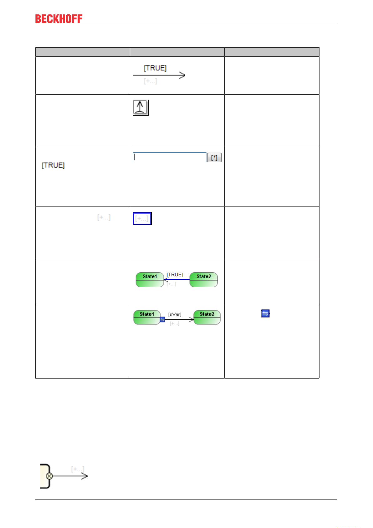
UML state diagram
Edit transition
User input in the Statechart Response in the Statechart Description
Selecting “Transition” in
“Toolbox”. Click on a state
(source state) in the Statechart,
then click on another state
(target state).
Click on a state (source state) in
the Statechart.
Double-click on the symbol An input field with IntelliSense
Two single clicks on :
Click once on a transition, the
action icon or the guard icon:
Click on the start or end of a
transition.
A transition with TRUE condition
and an action icon is created.
Use this method to generate a
transition between existing
states.
The icon through which an
outgoing transition can be added
to the selected state is available.
If you use it, the state is
extended with an outgoing
transition. The target state is
determined with a further click.
functionality opens. Select a
Boolean variable or a Boolean
expression. When the required
option is selected in IntelliSense,
it can be activated by doubleclicking or by focusing plus
[Enter].
An input field with IntelliSense
functionality opens. Select a
method or action. When the
required option is selected in
IntelliSense, it can be activated
by double-clicking or by focusing
plus [Enter].
The transition is selected
(indicated by a blue arrow). A
selected transition can be moved
via drag & drop. The position of
the linked states remains
unchanged.
The symbol enables
reconnecting of the transition,
while retaining the existing
transition configuration. You can
pull the symbol to another source
or target state in order to connect
the transition there. The
corresponding condition and
action are retained.
7.4.8 Completion Transition
A completion transition is unconditional. That is, it has no guard condition that triggers a switching
operation. Instead, it switches without an additional condition, once the source state has been fully
processed. During the next task cycle any action that may have been assigned is executed.
All outgoing transitions of a start state and a fork/join are completion transitions. A composite state can also
have a completion transition (depending on the application case of the composite state).
TF1910 77Version: 2.3
Page 78

UML state diagram
A completion transition is displayed as a thin arrow pointing to the target state. The small circle with a cross
at the start of the arrow indicates that it is a completion transition.
Properties
“Property” Description
"Relationship type" Completion transition (not editable)
“Priority” 1 (not editable)
Edit completion transition
The user inputs in the Statechart editor can be summarized as follows:
User input in the Statechart Response in the Statechart Description
Activate “Choice” in “Tool”.
Select “Completion transition” in
the toolbox. Click on a state and
then on another state (target
state).
Click on .
Click on the transition itself or on
the action icon.
Double-click on .
Click on the start or end of a
completion transition.
An unconditional transition with
an action icon is created. This
method for generating a
transition is used if the transition
is to link existing states.
The icon is available when the
corresponding state is selected.
If you use it, the state is
extended with an outgoing
completion transition. The target
state is determined with a further
click.
The transition is selected
(indicated by a blue arrow). A
selected transition can be moved
via drag & drop. The position of
the linked states remains
unchanged.
An inline editor opens. When you
start typing, the corresponding
components appear under
IntelliSense choices. A program/
method/action can be selected
by double-clicking.
The symbol enables
reconnecting of the transition,
while retaining the existing
transition configuration. You can
pull the symbol to another source
or target state in order to connect
the transition there. The
corresponding action is
maintained.
7.4.9 Exception Transition
An exception transition controls the switching to the next state or pseudo state, if an error or an exception
occurs. It has a guard condition and an optional action.
The source state is usually a composite or orthogonal state. Exception transitions cannot be used for
"normal" states. However, a "normal" state is active as a rule within the composite or orthogonal state, which
has an exception transition.
TF191078 Version: 2.3
Page 79

UML state diagram
An exception transition ends the currently running execution and switches to the state that is foreseen for the
reaction to this event. In this state the error handling and exception behavior are defined. Triggered by an
exception, the exception transition ends the process of the currently active state or substate. The execution
of the DO action(s) currently being executed will be completed.
The exception transition is used to exit a composite state from every substate. Its state is evaluated
after the DO action for the active state has been executed. Thus, even if the condition for the exception transition is already TRUE on the first occurrence of a composite state, the DO action of the
first state is executed. Since ENTRY and EXIT actions are not tied to conditions, they are always
executed independent of the exception transition.
An exception transition can be interpreted such that it does not originate from a composite state, but
directly from each substate. The conditions for the exception transitions are evaluated after their
DO actions. Since ENTRY and EXIT actions are not tied to conditions, they are always executed independent of the exception transition.
An exception transition is indicated by a red dashed arrow pointing to the next state.
Pseudo exception transitions
A pseudo exception transition replaces the end state in a composite state. It is indicated by a blue dashed
arrow.
In some cases it is clearer to draw a transition at the edge of the composite state whose condition is used as
a basis for exiting the whole composite state, instead of an end state in a composite state that is linked to
many transitions. This is similar to an exception transition, but without the interpretation that this represents a
malfunction. It is therefore referred to as a pseudo exception transition. A pseudo exception transition has no
influence on the cyclic execution behavior.
TF1910 79Version: 2.3
Page 80

UML state diagram
Properties
“Property” Description
"Relationship type" Exception transition (not editable)
“Priority” Priority, which determines the processing sequence
Sample: 3
Note: If the state has further transitions and you change the
priority, all transitions are affected by the change and are
automatically adjusted.
“Pseudo exception”
• : Exception transition. The arrow is shown with a dashed
red line in the editor. [Default setting]
• : Pseudo exception transitions. The arrow is shown with a
dashed blue line in the editor. If the condition is met, the state
is exited. However, it is not a fault signal that triggers
advancing.
"Rising edge"
• : If the guard condition returns a rising edge (from 0 to 1),
the transition is passed through and the state transition is
executed.
Tip: In the editor a transition that behaves in this way is marked
with the symbol .
• : If the guard condition is TRUE, the transition is passed
through.
TF191080 Version: 2.3
Page 81

Edit exception transition
User input in the Statechart Response in the Statechart Description
Select “Exception transition” in the
toolbox. Click on a composite state
(source state) and then on another
state (target state).
An exception transition with TRUE
condition and an action icon is
created.
UML state diagram
Click on a composite state (source
state) in the Statechart.
Double-click on the symbol An input field with IntelliSense
Click twice on the symbol
Click on the transition, the action
icon or the guard icon.
The icon through which an
outgoing exception transition can
be added to the selected state is
available. If you use it, the state is
extended with an outgoing
exception transition. The target
state is determined with a further
click.
functionality opens. Select a
Boolean variable or a Boolean
expression. When the required
option is selected in IntelliSense, it
can be activated by double-clicking
or by focusing plus [Enter].
An input field with IntelliSense
functionality opens. Select a
method or action. When the
required option is selected in
IntelliSense, it can be activated by
double-clicking or by focusing plus
[Enter].
The transition is selected (indicated
by a blue arrow). A selected
transition can be moved via drag &
drop. The position of the linked
states remains unchanged.
Click on the start or end of an
exception transition.
The symbol enables
reconnecting of the transition, while
retaining the existing transition
configuration. You can pull the
symbol to another source or target
state in order to connect the
transition there. The corresponding
condition and action are retained.
7.5 Object Properties
1. Select an UML Statechart in the project tree.
2. Open the context menu and select Properties or click on View > Properties.
The tabs that are relevant for UML are described below.
UML
• Abortable:
◦ Option available for: all Statecharts
TF1910 81Version: 2.3
Page 82

UML state diagram
◦ Option enabled (default): Processing of the Statechart can be aborted. Such a Statechart has an
additional internal variable: _UML_SC_<name>.Abort.
If this variable is set with IEC code, processing of the Statechart can be stopped immediately,
regardless of the internal state.
◦ Option disabled: Processing of the Statechart cannot be aborted.
• UseVarInst:
◦ Option available for: Statecharts, which were created as "Method" program elements and belong
to a function block
◦ Option enabled (default): The data of the Statechart methods are not temporary; they are held as
instance variables for the corresponding function block. If you declare the variables of the method
as VAR_INST, the data are held in the same way as for a function block and are no longer
temporary, so that the Statechart is passed through in several task cycles as usual.
◦ Option disabled: The data of the Statechart methods are held on a temporary basis. Methods and
their data are usually temporary. If you implement a method with the implementation language
UML Statechart and disable the option “UseVarInst”, the method behaves like a cycle-internal
state and reinitializes the data at the start of the task cycle. In this case only cycle-internal states
can be used.
◦ Note that this option is only available for Statechart methods that belong to a function block, not for
methods that belong to a program, since programs cannot contain VAR_INST declarations.
7.6 Online Mode
The behavior of Statechart objects in online mode corresponds to the normal online behavior in TwinCAT 3.
As usual it is possible to monitor a loaded application, write or force variables, set breakpoints or process a
program in single cycles.
In online mode an active state is shown in blue, an active composite state in light blue. In online mode the
value of a transition expression is displayed next to the transition. If the transition consists of only one
transition variable, the value of the variable can be changed for writing or forcing by double-clicking on the
monitoring value. If a value has been prepared for writing or forcing, this is indicated in the top right corner of
the monitoring area (see the monitoring field of the transition variable bLeaveState4 in the center of righthand edge in the image below: the blue corner indicates that the variable value TRUE is ready for writing or
forcing).
An additional debugging option is provided by transferring the variables of a transition to the watch list via a
command. To this end select Add Watch [}56] from the context menu of the transition. This command is
particularly useful if a transition expression consists of a combination of several variables (e.g. "bCondition1
AND bCondition2"). If you execute the command Add Watch for this transition, both variables of the
transition expression are added to the watch list, i.e. bCondition1 and bCondition2. This gives you a simple
overview of which sub-signal of the overall expression does not yet have the required value for switching to
the next state.
Furthermore, the commands Go To Definition [}56] and Find All References [}56] are supported for
transitions.
TF191082 Version: 2.3
Page 83

UML state diagram
All possible positions for breakpoints are shown as white circles with grey edge in the Statechart. To set a
breakpoint, select a circle. The circle is highlighted in grey: .
Select Debug > Toggle Breakpoint or press [F9]. The program stops at the breakpoint, and the point is
highlighted in yellow in the Statechart.
Online Change
Offline edits to an existing Statechart can usually be loaded to the controller with an online change without
re-initializing the chart if you change transitions, conditions, priorities, actions or names. The state that was
active before the online change is thus still active after the online change.
TF1910 83Version: 2.3
Page 84

UML state diagram
However, in the case of an online change the Statechart is always restarted –i.e. the start state is activated –
if a state or a region is added, removed or replaced. This also applies to implicit states such as the
"Selection" element, or to the property for making a Statechart "abortable".
TF191084 Version: 2.3
Page 85

8 FAQ
OOP and UML
Does object-oriented programming (OOP) and UML always have to be used together?
• The combined use of OOP and UML offers many benefits (see next question), although it is not
compulsory. Object-oriented programming of applications is also possible without using UML. Likewise,
UML can be used in PLC projects, which are not based on object-oriented programming.
What are the benefits of using OOP and UML together?
• In order to make the most of OOP, the structure of an object-oriented software should be designed and
created before the implementation (e.g.What classes are available, what is their relationship, what
functionalities do they offer, etc.). Before, during and after programming, documentation helps to
understand, analyze and maintain the software.
• As an analysis, design and documentation tool for software, UML offers options for planning, creating
and documenting the application. UML is particularly suitable for object-oriented implementations,
since modular software is particularly suitable for representation with the aid of a graphical language.
• For sample, the class diagram is used for analyzing and creating the program structure. The more
modular the software structure, the easier and more efficient the class diagram can be used
(e.g.Graphical representation of separate function blocks with individual methods for providing the
functionalities etc.).
• The state diagram can be used to specify the sequence of a system with discrete events. The more
consistent the object- and event-orientation of the software structure, the more transparent and
effective the state machines can be designed (e.g.The behavior of modules/systems is based on a
state model with states (such as startup, production, pause); within the states corresponding
functionalities are called, which are encapsulated in methods (such as startup, execute, pause) etc.).
FAQ
UML state diagram methods with deactivated "UseVarInst" option
The following three queries refer to methods with the implementation language UML state diagram, which in
addition meet one of the following conditions:
• The state diagram method belongs to a program.
• The state diagram method belongs to a function block, and the option UseVarInst of the method is
disabled.
State diagram methods that meet these conditions are referred to as "the methods mentioned" in the
questions below.
Further information on the option UseVarInst can be found under UML state diagram > Object properties.
[}81]
Why can these methods only contain cycle-internal states, and why is there no online view?
• As a general rule, all data of a method are temporary and only valid while the method is executed
(stack variables). If, however, a method variable is declared as instance variable with VAR_INST, it is
not stored on the methods stack, but on the stack for the function block instance. It therefore behaves
like other variables of the function block instance and is not reinitialized with each call of the method.
• Since the data of the state diagram method mentioned are not declared as instance variables, they are
cycle-internal state machines. The states contained in the diagrams are therefore switched cycleinternally, not by the task cycle, since the method execution "restarts" with each task cycle, due to the
temporary nature of the data management. Online view is therefore not available for these state
diagram methods, since the variables of the state machine are temporary, and the active state can
change repeatedly within a cycle.
• This is in contrast to state diagrams without temporary data management (e.g. programs or function
blocks as state diagram, function block method as state diagram with UseVarInst option enabled), in
which the states are switched by the task cycle as standard and can optionally be configured as "cycleinternal".
Why does the tool list for the methods mentioned not contain composite states, forks and joins?
TF1910 85Version: 2.3
Page 86

FAQ
• Since the data of these methods are temporary and only valid while the method is executed, the UML
state diagram methods can only have cycle-internal states (see previous question).
• A composite state would therefore have to be completed within a cycle. This means the element would
always be processed sequentially, even if execution of a region is not completed.
• This behavior would therefore be fundamentally different than for "normal" composite states, which can
remember their internal state.
• So as not to offer different behaviors for a composite state, depending on the POU type with which the
element is used, the composite states are not allowed in the methods mentioned.
• Since forks and joins are only permitted in conjunction with composite states, these elements are not
available in den state diagram methods mentioned.
What should be considered when programming the methods mentioned? What could be the reason
for high system load when these methods are executed?
• As explained under the previous questions, the UML state diagram methods are cycle-internal state
machines. Therefore, they are operated cycle-internally, not based on the task cycle.
• This means that completion of the actions of an internal state is followed immediately by the transition.
The transition condition is checked immediately, and the transition action is executed when the
condition is met. Also, the system immediately switches to the target state when the transition condition
is met.
• If the transition condition is not met, the system does not switch to the target state, and the current
state remains active. Due to the cycle-internal states, the DO action for the current state is called again
in the same cycle, if the maximum number of DO-cycle calls was not yet reached.
◦ Max. DO-cycle calls: The maximum number of DO-cycle calls for a state can be configured,
whereby a value between 1 and 32767 can be set. This number indicates the maximum number of
DO-action calls.
• Note the following: If the transition condition is not met during the whole task cycle, the DO-action of
the current active state is executed in this cycle until the maximum number of DO-cycle calls in this
state is reached.
Sample: If a value of 32767 is set for "max. DO-cycle calls" and the transition condition is not met during the
task cycle, the DO-action of the corresponding state is executed 32767 times in a cycle! Since this could
lead to high system load, depending on the scope of the DO-action, the state machine and in particular the
transition condition and the maximum number of DO-cycle calls should be verified for compliance with the
required application behavior.
Also see about this
2 Object Properties [}81]
TF191086 Version: 2.3
Page 87

Samples
9 Samples
9.1 UML class diagram
9.1.1 1 Basics
This UML class diagram example illustrates the basic functionality of the UML Class Diagram [}16].
Sample project: https://infosys.beckhoff.com/content/1033/TF1910_Tc3_UML/Resources/
zip/8158825227.zip
ClassDiagram_1
This class diagram illustrates the structure of the PLC project. It contains various PLC elements (such as
function block, interface, global variable list etc.).
The class diagram also illustrates the relationship between the elements (inheritance between function
blocks, implementation of an interface, instantiation of a function block).
ClassDiagram_2
This class diagram explains and explores the following basic functionalities:
• Visualize existing element from the cross-references on the diagram
◦ Display the Tools window
◦ Select FB_InfoData on the class diagram
◦ Tools window: Elements that are related to the selected element but are not included in the class
diagram are displayed under the headings "Incoming cross-references" and "Outgoing crossreferences".
◦ You can drag & drop the element onto the diagram, so that the element is shown in the class
diagram.
◦ For more information see Adding existing elements to a diagram [}18].
• Visualize existing element from the project tree on the diagram
◦ Select an element of type POU, INTERFACE, GVL or DUT in the project tree and drag & drop it
onto the opened class diagram.
◦ Drop it in a suitable location to visualize it there.
◦ The corresponding element is then displayed in the diagram. If relationships with already shown
elements exist, these are displayed automatically.
◦ For more information see Adding existing elements to a diagram [}18].
• Adding new elements or creating new relationships between elements
◦ Use the elements of the Tools window.
◦ For more information, see Editing a class diagram [}20] and Elements [}23].
9.1.2 2 Simple machine
This UML class diagram sample illustrates the basic functionality of the UML Class Diagram [}16] based on
a machine with object-oriented programming.
Note that the modules have not been functionally implemented. The sample is designed to describe
the functionalities of the UML class diagram and to demonstrate them using an exemplary program
structure.
TF1910 87Version: 2.3
Page 88

Samples
The class diagram can be used to create, extend and change the structure of a PLC program.
In addition, the class diagram can be used to document and comprehend the structure of a PLC program, as
illustrated in this sample.
Sample project: https://infosys.beckhoff.com/content/1033/TF1910_Tc3_UML/Resources/
zip/9007207413567883.zip
Machine modules
The application has the following levels and modules.
Machine level: Machine (FB_Machine)
Subsystem level: Ejection (FB_Ejector)
Submodule level: Cylinder with or without hardware feedback signal (FB_Cylinder, FB_CylinderFeedback)
Inheritance
Since all these function blocks have common features (common data and functionalities), a base class is
provided where these common features are implemented once for all function blocks. These
implementations are passed on to the subclasses via the inheritance mechanism offered by object-oriented
programming.
• The four machine modules extend FB_ModuleRoot.
Furthermore, the cylinder with feedback functionality represents an extension of the cylinder without this
functionality. Therefore, inheritance is also used here.
• FB_CylinderFeedback extends FB_Cylinder.
Interface
To define the requirements for different cylinder types, the basic methods and properties that a cylinder must
provide are defined in an interface.
• I_Cylinder defines the cylinder requirements.
• FB_Cylinder implements I_Cylinder.
Instantiation
• MAIN instantiates FB_Machine.
• FB_Machine instantiates FB_Ejector twice, since the machine has two ejector modules.
• FB_Ejector instantiates I_Cylinder, FB_Cylinder and FB_CylinderFeedback. As an example, only one
cylinder is active at a time, either the cylinder with feedback functionality or the cylinder without
feedback functionality. The interface variable iCylinder is assigned the currently active cylinder
instance. This allows the active cylinder to be controlled in a generalized manner via the interface
variable.
• FB_ModuleRoot instantiates ST_Error.
9.2 UML state diagram
In the following UML SC samples, the level of difficulty and the scope increase with ascending number of the
sample.
9.2.1 1 Lamp
This UML state diagram sample illustrates the basic functionality of the UML state diagram [}49] and
contains the following UML SC elements:
• Start State [}57]
TF191088 Version: 2.3
Page 89

Samples
• State [}58]
• Transition [}75]
Sample project: https://infosys.beckhoff.com/content/1033/TF1910_Tc3_UML/Resources/
zip/8158544011.zip
Overview
UML SC is used to program the behavior of a lamp, which can be switched on and off via a switch on the
visualization. The lamp has two states, "On" and "Off".
Each state contains one ENTRY action and one DO action.
• The lamp is switched on or off in the ENTRY actions. The ENTRY action is called once whenever the
corresponding state is activated.
• An ON or OFF counter is incremented in the DO actions. This indicates that a DO action is called
permanently as long as the corresponding state is active.
• The value of the switch is requested as a transition between the states.
Visualization
In addition to the convenient online mode [}82] of the UML SC diagram, the behavior of the lamp and the
values of the counters can be followed via the visualization.
9.2.2 2 Pedestrian traffic light
This UML state diagram sample illustrates the basic functionality of the UML state diagram [}49] and
contains the following UML SC elements:
• Start State [}57]
• State [}58]
• Transition [}75]
Sample project: https://infosys.beckhoff.com/content/1033/TF1910_Tc3_UML/Resources/
zip/8158546187.zip
Overview
UML SC is used to program the behavior of a pedestrian traffic light. A green-phase request can be sent via
a button on the visualization. The pedestrian traffic light has the two states, "Red" and "Green“.
If a green phase is requested, the traffic light switches to green after the time "cTimeWaitForGreen" has
elapsed. The traffic light switches back to red once the time "cTimeGreenPhase" has elapsed.
The two states "Red" and "Green" each contain an ENTRY action and a DO action.
• The ENTRY actions are used to switch the traffic light to red or green. In addition, the respective timer
function block (of type TON) is reset. The ENTRY action is called once whenever the corresponding
state is activated.
• In the DO actions a Red or Green counter is incremented. This indicates that a DO action is called
permanently as long as the corresponding state is active. The respective timer function block is also
called.
• The Q output of the respective timer function block is used as a transition between the states, so that
the state is changed after the corresponding time has elapsed.
Visualization
In addition to the convenient online mode [}82] of the UML SC diagram, the behavior of the pedestrian
lights, the values of the counters and the waiting time that has already elapsed can be tracked via the
visualization.
TF1910 89Version: 2.3
Page 90

Samples
9.2.3 3 SaveText simulation
This UML state diagram sample illustrates the basic functionality of the UML state diagram [}49] and
contains the following UML SC elements:
• Start State [}57]
• State [}58]
• Transition [}75]
• Choice [}74]
• Composite State [}62]
• Completion Transition [}77]
Sample project: https://infosys.beckhoff.com/content/1033/TF1910_Tc3_UML/Resources/
zip/8158650763.zip
Overview
UML SC is used to simulate the behavior of an application in which text is to be saved in XML or text format.
The information is then to be sent to a client and a master.
This behavior has not actually been implemented in the sample project. Instead, the outer shell or basic
structure of the state machine is implemented using UML SC as an example.
States
The UML SC diagram has the following states:
• InitState
• XmlFormat
• TextFormat
• PublishToMaster
• PublishToClient
Counter/call frequency
The states each contain a DO action and an ENTRY and/or EXIT action. Each action increments a
corresponding counter. This indicates that:
• the ENTRY action is called once each time the corresponding state is activated;
• the EXIT action is called once each time the corresponding state is exited;
• the DO action is called permanently as long as the associated state is active.
Selection element
If the "XmlFormat" or "TextFormat" state is activated, the selection element is used as a decision basis. The
element has two outgoing transitions. The transition with the higher priority (i.e. with the lower priority
number) is checked first. If the associated transition condition is met, the target state is activated.
Composite state
The "PublishToMaster" and "PublishToClient" states are located in different regions of a composite state, so
that they are processed in pseudo-parallel mode. This means that both states are active simultaneously, but
the region with the higher priority (i.e. with the lower priority number) is executed first. Colored highlighting on
the visualization indicates which region was processed first. Furthermore, during the execution of the sample
project it becomes apparent that the composite state is only exited when both substate machines have
reached their end state.
TF191090 Version: 2.3
Page 91

Samples
Project modification possible: The priorities of the regions can be changed by adjusting the number in the
upper right corner of the region. If you configure Region1 with priority 1 and download this change via an
online change, next time you activate the composite state you can see that "Client first" is now highlighted
instead of "Master first". Consequently, Region1 was executed first.
Visualization
In addition to the convenient online mode [}82] of the UML SC diagram, the behavior of the state machine
and the values of the counters can be tracked via the visualization. Switches on the visualization facilitate
switching back and forth between the states.
The values of the transition conditions can be changed not only via the visualization or the declaration editor of the FB, but also directly via the UML SC diagram.
If the transition consists of only one transition variable, the value of the variable can be changed for writing or
forcing by double-clicking on the monitoring value. If a value was prepared for writing or forcing, this is
indicated in the upper right-hand corner of the monitoring area (see also: Online Mode [}82]).
9.2.4 4 Call Behavior - Basis
This UML state diagram example shows the basic call behavior of the UML state diagram [}49] and contains
the following UML SC elements:
• Start State [}57]
• State [}58]
• Transition [}75]
• Composite State [}62]
• Completion Transition [}77]
• Exception Transition [}78]
Sample project: https://infosys.beckhoff.com/content/1033/TF1910_Tc3_UML/Resources/
zip/8158652939.zip
Overview
The following sub-aspects illustrate the call behavior of states and composite states. A programming tool can
be used to illustrate the different call aspects (Programming tool => Call aspect).
• Counter => Call frequency
• Entering the called state action in an array => Call sequence
• Task cycle IDs => Assignment of the call to the cycle ID
Both use cases are applied for the composite state:
• Grouping/Nesting, in which case the composite state has its own ENTRY/DO/EXIT actions
• Parallel sub-state machines
Counter => Call frequency
Each ENTRY/DO/EXIT action, that is called in a state or a composite state, increments a corresponding
counter. This illustrates the call frequency of an action and indicates that:
• the ENTRY action is called once each time the associated (composite) state is activated;
• the EXIT action is called once each time the associated (composite) state is exited;
• the DO action is called permanently as long as the associated (composite) state is active;
• a composite state with a region (use case Grouping/Nesting) is activated if none of the inner states was
previously active and as soon as one of the inner states is activated;
TF1910 91Version: 2.3
Page 92

Samples
• a composite state with a region (use case Grouping/Nesting) remains active as long as one of the inner
states is active;
• a composite state with a region (use case Grouping/Nesting) is exited if one of the inner states was
previously active and this state is exited so that none of the inner states is now active;
• it depends on the option "Execute DO actions even if inner composite states are active" whether the
DO action of an outer composite state (in the sample "CompositeState1") is still called if an inner
composite state is active (in the sample project: „CompositeState2“).
Entering the called state action in an array => Call sequence
Each ENTRY/DO/EXIT action that is called in a state or in a composite state enters its name (e.g.
"State1__Entry") into an array. This illustrates the call sequence of the different actions and indicates that:
• the basic call sequence for a state is: first ENTRY, then DO, then EXIT. In the sample project:
◦ State1__Entry
◦ State1__Do
◦ State1__Exit
• if an inner state of a composite state with a region (use case Grouping/Nesting) is activated and the
composite state is also activated, the call sequence is "from outside to inside": outer state EXIT,
composite state ENTRY, inner state ENTRY, composite state DO, inner state DO. In the sample
project:
◦ State1__Exit
◦ Comp1_Entry
◦ State2__Entry
◦ Comp1_Do
◦ State2__Do
• an inner composite state can be exited via a (pseudo) exception transition of the outer composite state
(in the sample project via the transitions: eLeaveComp1_ToState1, eLeaveComp1_ToComp3).
• if a composite state is exited, e.g. via a (pseudo) exception transition, the call sequence is "from inside
to outside": inner state EXIT, possibly inner composite state EXIT, outer composite state EXIT, outer
composite state ENTRY. In the sample project:
◦ State4__Exit
◦ Comp2_Exit
◦ Comp1_Exit
◦ State7__Entry
• in a composite state with several regions, the region with the higher priority, i.e. with the lower priority
number, is called first. In the sample project:
◦ State7__Entry
◦ State7__Do
◦ State6__Entry
◦ State6__Do
Task cycle IDs => Assignment of the call to the cycle ID
Each ENTRY/DO/EXIT action that is called in a state or a composite state stores the cycle ID of the first and
last call. This illustrates which call takes place in which cycle and indicates that:
• when a state is activated, the ENTRY and DO actions are called within the same cycle.
In the screenshot "Visu_B_CallingOrder_CycleNr" contained in the ZIP file:
◦ State1 / ENTRY call: 516 (ID of the cycle in which the call occurred)
◦ State1 / DO first call: 516
• when a state is exited, the EXIT action is called in the subsequent cycle of the last DO call.
In the screenshot "Visu_B_CallingOrder_CycleNr" contained in the ZIP file:
◦ State1 / DO last call: 1415
TF191092 Version: 2.3
Page 93

Samples
◦ State1 / EXIT call: 1416
• when a state is exited, the EXIT action of that state is called in the same cycle as the ENTRY and DO
actions of the activated state.
In the screenshot "Visu_B_CallingOrder_CycleNr" contained in the ZIP file:
◦ State2 / DO last call: 1762
◦ State2 / EXIT call: 1763
◦ State3 / ENTRY call: 1763
◦ State3 / DO first call: 1763
• when a state is exited and a composite state with a region and own actions is activated, the EXIT
action of the exited state is called in the same cycle as the ENTRY and DO actions of the activated
(composite) state.
In the screenshot "Visu_B_CallingOrder_CycleNr" contained in the ZIP file:
◦ State1 / DO last call: 1415
◦ State1 / EXIT call: 1416
◦ CompositeState1 / ENTRY call: 1416
◦ State2 / ENTRY call: 1416
◦ CompositeState1 / DO first call: 1416
◦ State2 / DO first call: 1416
• when a composite state with a region and its own actions is deactivated, the EXIT action of the exited
(composite) state is called in the same cycle as the ENTRY and DO actions of the activated state.
In the screenshot "Visu_B_CallingOrder_CycleNr" contained in the ZIP file:
◦ State4 / DO last call: 2367
◦ CompositeState2 / DO last call: 2367
◦ CompositeState1 / DO last call: 2367
◦ State4 / EXIT call: 2368
◦ CompositeState2 / EXIT call: 2368
◦ CompositeState1 / EXIT call: 2368
◦ State7 / ENTRY call: 2368
◦ State6 / ENTRY call: 2368
Visualization
In addition to the convenient online mode [}82] of the UML SC diagram, the behavior of the state machine
and the values of the counters, the table and the task cycle IDs can be tracked via the visualizations. The
visualization also contains switches for switching between the states and for resetting the values.
In order to facilitate familiarization with the sample project, two visualizations with different information
content are included:
• Visu_A_CallingOrder contains:
◦ Counter => Call frequency
◦ Entering the called state action in an array => Call sequence
• Visu_B_CallingOrder_CycleNr extends Visu_A by:
◦ Task cycle IDs => Assignment of the call to the cycle ID
The values of the transition conditions can be changed not only via the visualization or the declaration editor of the FB, but also directly via the UML SC diagram.
If the transition consists of only one transition variable, the value of the variable can be changed for writing or
forcing by double-clicking on the monitoring value. If a value was prepared for writing or forcing, this is
indicated in the upper right-hand corner of the monitoring area (see also: Online Mode [}82]).
TF1910 93Version: 2.3
Page 94

Page 95

More Information:
www.beckhoff.com/tf1910/
Beckhoff Automation GmbH & Co. KG
Hülshorstweg 20
33415 Verl
Germany
Phone: +49 5246 9630
info@beckhoff.com
www.beckhoff.com
 Loading...