

Page 1
Manual | EN
TE1010
TwinCAT 3 | Realtime Monitor
2020-09-24 | Version: 1.3
Page 2

Page 3

Table of contents
Table of contents
1 Foreword ....................................................................................................................................................5
1.1 Notes on the documentation..............................................................................................................5
1.2 Safety instructions .............................................................................................................................6
2 Overview.....................................................................................................................................................7
3 Basic principles .........................................................................................................................................8
3.1 TwinCAT 3 Real-Time .......................................................................................................................8
3.2 Display in the Real-time Monitor......................................................................................................12
3.3 Use of cursors .................................................................................................................................16
4 Quick start................................................................................................................................................20
5 Reference, user interface........................................................................................................................22
5.1 Menu bar .........................................................................................................................................22
5.1.1 Project.............................................................................................................................. 22
5.1.2 User contexts................................................................................................................... 23
5.1.3 Tools ................................................................................................................................ 24
5.1.4 Info................................................................................................................................... 25
5.2 Toolbar - Real-time Monitor toolbar.................................................................................................25
5.3 Project tree ......................................................................................................................................26
5.4 Display window................................................................................................................................28
5.5 Properties window ...........................................................................................................................29
5.5.1 Project node..................................................................................................................... 29
5.5.2 Context node ................................................................................................................... 30
5.5.3 Marker group element...................................................................................................... 31
5.6 Cursor window.................................................................................................................................32
5.7 Event window ..................................................................................................................................32
6 PLC API.....................................................................................................................................................33
6.1 Function blocks................................................................................................................................33
6.1.1 FB_RTMon_LogMark ...................................................................................................... 33
6.1.2 FB_RTMon_LogMarkBase .............................................................................................. 36
6.2 Data types .......................................................................................................................................37
6.2.1 ST_RTMon_MarkDef....................................................................................................... 37
6.3 Global constants..............................................................................................................................38
6.3.1 TcMarkOption .................................................................................................................. 38
7 C++ API.....................................................................................................................................................39
7.1 Data types .......................................................................................................................................39
7.1.1 TcMark16......................................................................................................................... 39
7.2 Classes............................................................................................................................................39
7.2.1 CTcLogMark .................................................................................................................... 39
7.3 Constants ........................................................................................................................................41
TE1010 3Version: 1.3
Page 4

Table of contents
TE10104 Version: 1.3
Page 5

Foreword
1 Foreword
1.1 Notes on the documentation
This description is only intended for the use of trained specialists in control and automation engineering who
are familiar with applicable national standards.
It is essential that the documentation and the following notes and explanations are followed when installing
and commissioning the components.
It is the duty of the technical personnel to use the documentation published at the respective time of each
installation and commissioning.
The responsible staff must ensure that the application or use of the products described satisfy all the
requirements for safety, including all the relevant laws, regulations, guidelines and standards.
Disclaimer
The documentation has been prepared with care. The products described are, however, constantly under
development.
We reserve the right to revise and change the documentation at any time and without prior announcement.
No claims for the modification of products that have already been supplied may be made on the basis of the
data, diagrams and descriptions in this documentation.
Trademarks
Beckhoff®, TwinCAT®, EtherCAT®, EtherCAT G®, EtherCAT G10®, EtherCAT P®, Safety over EtherCAT®,
TwinSAFE®, XFC®, XTS® and XPlanar® are registered trademarks of and licensed by Beckhoff Automation
GmbH.
Other designations used in this publication may be trademarks whose use by third parties for their own
purposes could violate the rights of the owners.
Patent Pending
The EtherCAT Technology is covered, including but not limited to the following patent applications and
patents:
EP1590927, EP1789857, EP1456722, EP2137893, DE102015105702
with corresponding applications or registrations in various other countries.
EtherCAT® is a registered trademark and patented technology, licensed by Beckhoff Automation GmbH,
Germany
Copyright
© Beckhoff Automation GmbH & Co. KG, Germany.
The reproduction, distribution and utilization of this document as well as the communication of its contents to
others without express authorization are prohibited.
Offenders will be held liable for the payment of damages. All rights reserved in the event of the grant of a
patent, utility model or design.
TE1010 5Version: 1.3
Page 6
Foreword
1.2 Safety instructions
Safety regulations
Please note the following safety instructions and explanations!
Product-specific safety instructions can be found on following pages or in the areas mounting, wiring,
commissioning etc.
Exclusion of liability
All the components are supplied in particular hardware and software configurations appropriate for the
application. Modifications to hardware or software configurations other than those described in the
documentation are not permitted, and nullify the liability of Beckhoff Automation GmbH & Co. KG.
Personnel qualification
This description is only intended for trained specialists in control, automation and drive engineering who are
familiar with the applicable national standards.
Description of symbols
In this documentation the following symbols are used with an accompanying safety instruction or note. The
safety instructions must be read carefully and followed without fail!
DANGER
Serious risk of injury!
Failure to follow the safety instructions associated with this symbol directly endangers the life and health of
persons.
WARNING
Risk of injury!
Failure to follow the safety instructions associated with this symbol endangers the life and health of persons.
CAUTION
Personal injuries!
Failure to follow the safety instructions associated with this symbol can lead to injuries to persons.
NOTE
Damage to the environment or devices
Failure to follow the instructions associated with this symbol can lead to damage to the environment or
equipment.
Tip or pointer
This symbol indicates information that contributes to better understanding.
TE10106 Version: 1.3
Page 7

Overview
2 Overview
The TwinCAT 3 Real-time Monitor enables precise diagnostics and optimization of the runtime behavior of
tasks in the TwinCAT 3 runtime. It offers a graphical representation of the temporal processing of real-time
tasks and their modules across all cores. In addition, user-defined processes and their dependencies can be
represented graphically through appropriate instrumentation of the control software.
The Real-time Monitor makes the time behavior of the control software on a target system completely
transparent and enables comprehensive time analysis. It thus supports both fault diagnosis and time
optimization of the configuration, especially on multi-core systems.
Installation
A separate installer is used for the installation. The license is activated as usual under TwinCAT 3.
Requirements
The Real-time Monitor can only be used for diagnosis of TwinCAT 3.1 runtimes from TwinCAT 3.1 version
4024.0 or higher.
It is suitable for Windows 10-based target systems, but not for target systems based on Windows CE.
Licensing
The TwinCAT 3 Real-time Monitor (TE1010) is an Engineering product. Licensing is therefore carried out
exclusively on the Engineering system.
There is no 7-day trial license available for this product.
TE1010 7Version: 1.3
Page 8

Basic principles
3 Basic principles
The following chapter describes the basic principles that should be read before using the TwinCAT 3 Realtime Monitor.
3.1 TwinCAT 3 Real-Time
According to the DIN 44300 standard, real-time / real-time operation is defined as follows:
Real-time operation is an operating mode of a computing system in which programs for the processing of
data are continuously operational in such a way that the processing results are available within a specified
period of time.
In other words, the output values of an application program (calculated based on the inner state and input
values) are available within a defined and guaranteed time. This defined time is also referred to as cycle
time.
The application program itself can consist of several program function blocks, which in turn call other
programs or function blocks etc. (see also IEC 61131-3 standard). The program blocks can be assigned to
real-time tasks, which in turn call them with a cycle time to be defined and a defined priority.
TwinCAT 3 Real-Time is a real-time extension that can be used in the current TwinCAT 3.1 version under
Microsoft Windows operating systems from Windows 7 or later. TwinCAT 3 Real-Time supports the following
features in order to meet the requirements described for the control of industrial processes:
• Real-time capable scheduling
• Parallel execution of processes
• Direct hardware access
In addition, TwinCAT 3 Real-Time also offers multi-core support to meet the ever-increasing demands for
high-performance and flexible/expandable control platforms. The available cores can either be used
exclusively for TwinCAT or shared with Windows. In the following sections, the cores are therefore referred
to as "isolated" or "shared.
Real-time capable scheduling:
TwinCAT 3 Real-Time works with the double-tick method. This means that both switching to real-time mode
and switching back is triggered by an interrupt. The interrupt when switching to the real-time mode also
starts the scheduling at the same time. After an adjustable period of time, but no later than after 90% of the
set cycle time, TwinCAT only on shared cores switches back in non-real-time mode, so that the guest
operating system has sufficient computing time available to comply with the response times required for
hardware functions etc. The isolated cores are an exception.
Scheduling refers to the (system) process that determines the processing sequence and the processing time
of the individual tasks, based on the defined cycle time and the defined priority. Strict adherence to the
processing time ensures that the real-time compliance described above is guaranteed.
Triggered by a synchronous basic tick on all real-time kernels, the scheduling for each real-time kernel is
calculated independently in TwinCAT 3 Real-Time. This guarantees that real-time tasks running on different
cores do not interfere with each other (unless already explicitly prevented in the user program through the
use of interlocks).
Scheduling in which the priority of a task is derived from its cycle time is also known as rate-monotonic
scheduling. Activating the option "Automatic Priority Management" automatically sets TwinCAT 3 Real-Time
to this value. Since this is not always the best solution for every application, the priorities can be adjusted
manually.
Exemplary representation of the call of a PLC task:
TE10108 Version: 1.3
Page 9
Basic principles
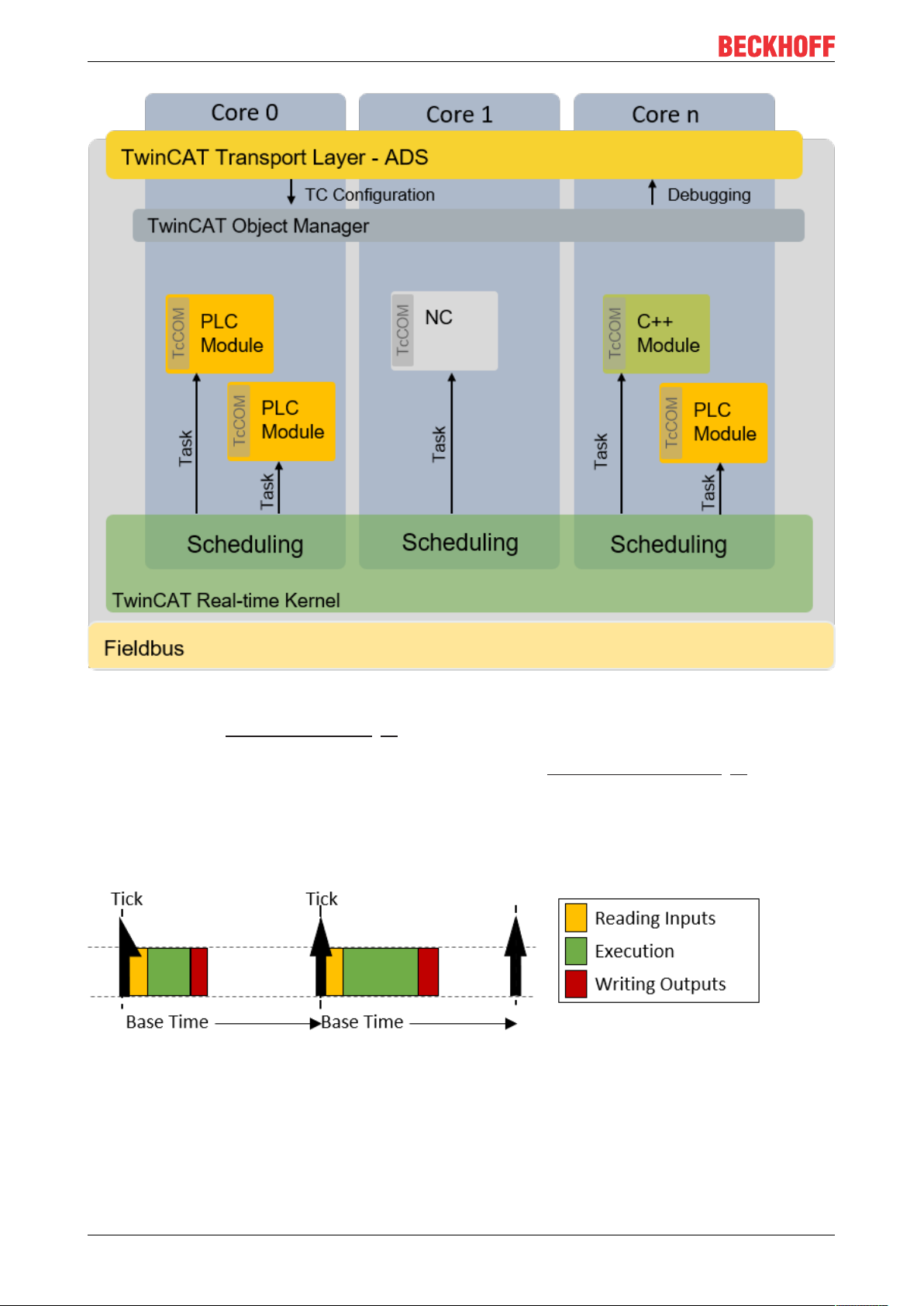
The figure shows the call of a PLC task. After the real-time tick has occurred, the PLC task is called by the
scheduler. This makes the current input values available to the PLC application (input update), followed by
processing of the application program (cycle update). Finally the results are written to the outputs (output
update). Once this has been completed, the device switches to non-real-time mode (double-tick). As shown
in the figure, the execution time of the user program may vary depending on which code is executed (based
on the internal state of the program). Thus the time when the outputs are written also varies. Depending on
which task a bus system is driven, this can cause the sending of the bus telegrams to vary (jitter) to the same
extent.
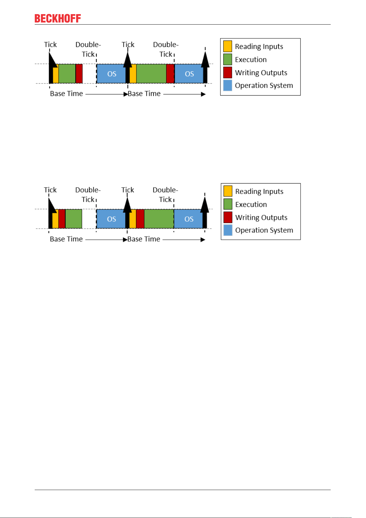
Sample call of a task with "IO at task start“
By using the "IO at task start" option, the processing sequence within a task can be changed so that after
reading the inputs, the outputs (of the previous cycle) are written directly before the application program is
executed. Although the outputs are not written until the next cycle, this setting has the advantage that the
time at which the outputs are written to the process/bus is exactly the same in each cycle.
Preemptive multitasking:
Preemptive multitasking means that the current state of a process (the CPU and floating point registers) is
saved in the event of an interrupt (e.g. by higher-priority processes), and the current process is paused. If
this happens, the scheduler determines the (new) process to be executed, based on the task priorities. Once
the process to be interrupted is complete, the process context is restored and the "old" process continues.
Direct hardware access:
In order to achieve deterministic (reproducible) real-time behavior, TwinCAT 3 Real-Time requires direct
hardware access. For this to be possible, TwinCAT 3 Real-Time must be executed in Windows kernel mode.
This makes it possible, among other things, for TwinCAT Real-Time to access the network ports directly and
send and receive real-time Ethernet telegrams (e.g. EtherCAT).
Schematic representation of the TwinCAT 3 runtime environment:
The following figure illustrates the structure of the TwinCAT 3.1 runtime environment in relation to
scheduling. The TwinCAT 3 runtime environment enables user modules to be executed in real-time. An
essential part of the TwinCAT 3 runtime environment therefore is the real-time driver, which is executed on
the cores that are activated for TwinCAT and handles the scheduling there. The latter takes place
independently on the individual cores.
TE1010 9Version: 1.3
Page 10
Basic principles
Isolated cores:
As described under Realtime scheduling [}8], TwinCAT uses a double-tick procedure to switch back to nonreal-time mode at a specified point in time. When switching between real-time mode and non-real-time
mode, the preceding process state is restored, as described under Preemptive multitasking [}9]. The
restoration takes some time, depending on how intensively the real-time and non-real-time programs use the
memory and in particular the cache. In order to eliminate these temporal effects, TwinCAT 3.1 Real-Time
allows cores to be isolated from the guest operating system. This eliminates the need to switch back,
resulting in more computing time for the real-time user program and better real-time quality (less jitter) by
avoiding the time effects associated with restoring the "old" process state.
Behavior when the cycle time is exceeded:
If the defined cycle time of a task is exceeded, processing of the "old" cycle continues in the next cycle. In
addition, the task exceed counter is incremented. Once processing of the old / previous cycle is complete,
the system immediately tries to start processing the tasks of the current cycle. If this is completed within the
current cycle, further processing is carried out as shown above.
TE101010 Version: 1.3
Page 11
Basic principles
If the second cycle that follows directly is also exceeded (in this case it is irrelevant whether the system is still
processing the first cycle or whether the second cycle has commenced), the current processing task is
completed, and processing of the next task does not commence until the next possible scheduled cycle start.
This means that several cycles may be lost. The exceedance counter is incremented accordingly.
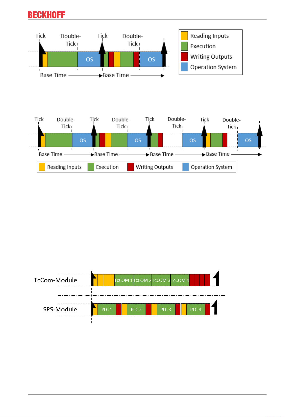
Differences in execution between PLC and "TcCom" runtime modules:
Processing of a TwinCAT task, in relation to the execution of runtime modules, is based on the following
sequence:
1. Copying of the inputs to the process images of the runtime modules called by the task.
2. Executing the modules according to the sort order (in ascending order).
3. Output update, which makes the outputs available accordingly. If this task drives an EtherCAT fieldbus, the frame is provided and sent during the output process image.
4. Post-cycle update: this is used, among other things, to trigger a cycle update when the "I/O at task
start" option is active.
If runtime modules are added to a task, they "log on" to the respective calls of the task. The only exceptions
are PLC runtime modules. For reasons of compatibility with TwinCAT 2, the PLC runtime modules directly
update the inputs and outputs. The difference between the two behaviors is shown in the following figure.
Four runtime modules can be seen in each case. Standard TwinCAT 3 runtime modules log on to the
corresponding method calls of the task. This means that all input updates (yellow) and output updates (red)
are triggered by the task and take place one after the other directly at the start or end of task processing. If
two of these modules communicate with each other via a mapping, they do not receive the current values
until the next cycle.
The PLC runtime modules independently perform an input and output update. If two PLC runtimes
communicate with each other, the runtime module that is executed second directly receives the current
values from the first runtime module. Thus, there is no cycle offset in the communication direction from first
runtime module to second runtime module, but there such an offset does exist in the other direction.
TE1010 11Version: 1.3
Page 12

Basic principles
3.2 Display in the Real-time Monitor
In simple terms, the TwinCAT 3 Real-time Monitor enables the display of grouped events. In order to avoid
confusion with the messages or alarms stored in the TwinCAT EventLogger, the data handled by the
TwinCAT 3 Real-time Monitor are referred to as (time) markers.
These markers can be used to represent the temporal behavior of tasks or user processes. For this purpose,
the markers are assigned an ID, a marker type, a context and a timestamp. In addition, if required a userdefined date formatted as UINT can be provided, in order to include additional information in the display in
the real-time monitor (e.g. error number, state of a state machine etc.).
Marker ID:
The marker ID is used to identify the displayed task / process. In other words, all markers relating to the
same task/process should use the same marker ID.
Marker type:
The TwinCAT 3 Real-time Monitor enables the display of events or processes / operations over time. For the
representation of processes / operations, these are marked as a sequence. A sequence can be divided into
one or more intervals. Markers can be typed to define the start or end of sequences or intervals. In addition,
they can also show events within an application over time. A distinction is therefore made between the
following types of markers:
1. Marker:
The marker can be used to log an event, e.g. the time of an alarm or the change of a state etc.
2. Sequence start:
A sequence start indicates the time when a task / process is allowed to start (higher-priority tasks /
processes may result in a delay).
3. Interval start:
An interval start specifies the time when a task / process actually starts. Due to interruptions etc., a sequence may contain several interval starts.
4. Interval stop:
An interval stop specifies the time when a task / process is no longer executed. This can happen, for
example, due to interruptions caused by higher-priority tasks or unfulfilled dependencies.
5. Sequence stop:
A sequence stop indicates the point in time at which a task may no longer run or a process is terminated.
Context:
A context describes a summary of markers or marker groups.
For the system tasks, all tasks that are processed on a core are combined into one context (e.g. core 0).
Such a (real-time) context thus maps the scheduling within a real-time kernel. For these real-time contexts,
only one of the tasks assigned to a context is active at any one time. This restriction does not apply to userspecific marker groups.
When using simple markers (by using FB_Mark), the user-specific marker groups are automatically grouped
according to their application ports. For example, all markers stored from within a PLC project with port 851
are assigned to a context with context ID 851 (hexadecimal 0x353).
When using more complex markers (based on the function block FB_RTMon_LogMarkBase [}36]), contexts
(i.e. correlations) can be defined independently. This could be, for example, a grouping by process type or by
machine modules (functional units).
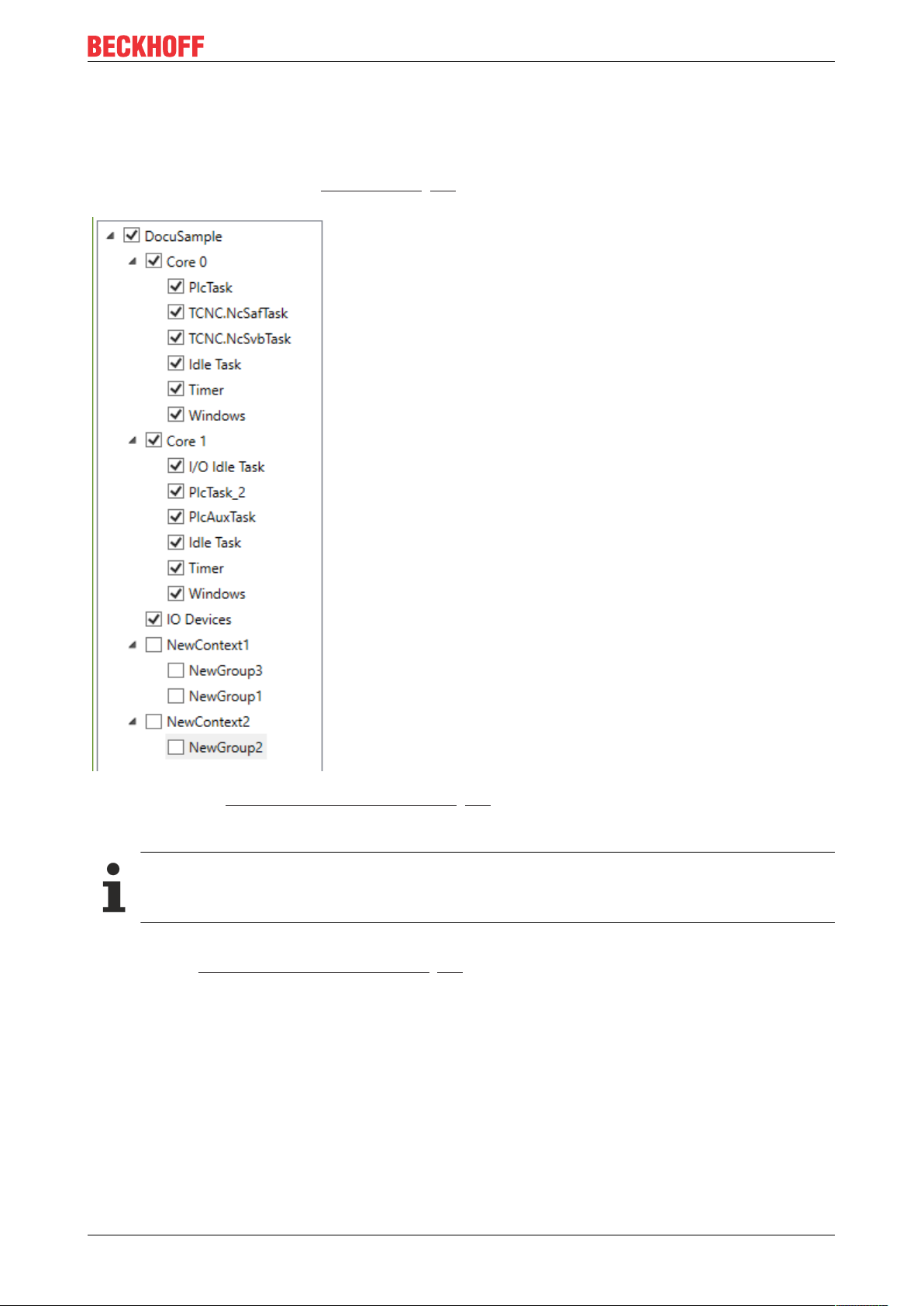
Display in the tree view:
As described above, all markers that describe the same task / process use the same marker ID. These
markers are combined into a marker group and are assigned an entry in the tree view of the TwinCAT 3
Real-time Monitor.
TE101012 Version: 1.3
Page 13
Basic principles
An entry with the corresponding task name is automatically created in the tree for the system tasks.
For user-related marker groups that describe processes, for example, this must be done manually. For each
detected user-specific marker group an entry NewGroup automatically appears in the tree, which can be
identified by the marker ID (corresponds to the group ID in the Properties window of the group). This group
can be renamed as required (see Context node [}30]).
As described under Display in the Real-time Monitor [}12], the individual marker groups are combined into
contexts. This happens automatically for the system tasks and when simple markers are used. When using
extended markers, the context ID that is transferred in the application code is used for this purpose.
The names of marker IDs (group IDs) and contexts can be exported for later reuse and subsequently re-imported.
In the chart display, a marker group (i.e. all markers of a task / process) is shown within one row. For more
information see Display in the Real-time Monitor [}13].
Chart display:
Symbols in the chart display:
TE1010 13Version: 1.3
Page 14

Basic principles
Sequence start
Sequence stop
Indicates an interval start or stop.
Marker
Example display:
The following diagram shows an example of a possible temporal behavior of a task. At time (1), the task
receives "permission" to run based on the set cycle time. The start may be delayed until time (2) due to
missing dependencies or due to higher priority tasks that are still active. At time (3) a marker was transferred.
This can be a "system event" marker or a user-defined marker. Detailed information is provided by a tooltip
associated with the marker. The marker itself has no influence on the temporal behavior of the task /
process. At time (4) the task is interrupted (once again for example due to an interlock or a higher-priority
task). At time (5) the task continues to run. At time (6) the task is finished.
Illustration of the processing of a PLC runtime module:
As described in section TwinCAT 3 Real-Time [}11], each PLC runtime module calls the update of the inputs
and outputs itself. The complete processing of the PLC takes place in the cyclic update of the task calling it.
For this reason, if detailed logging is activated, processing of the PLC is mapped in the cyclic update of a
task. The following figure illustrates this by means of an example. Time (1) shows the execution of the input
update of the PLC runtime module. Cyclic processing of the PLC code takes place in area (2), which is
interrupted by another task in the example shown here. Once processing is completed, the output update of
the PLC runtime module takes place at time (3). In the example shown here, the task itself does not perform
an input or output update.
Detailed logging:
TE101014 Version: 1.3
Page 15

Basic principles
The option "detailedLogging" (see Project node [}29] or Context node [}30]) offers a detailed
representation of the execution of real-time tasks (also within a task). The following two figures illustrate the
difference.
Standard logging enabled:
DetailedLogging enabled:
Representation of the task references:
The option Show Task Reference (see Marker group element [}31]) enables the assignment of user
processes to the tasks on which they are executed to be made visible in the TwinCAT 3 Real-time Monitor.
This is represented by dashed lines. The following figure shows the assignment of the user process shown in
orange to a PLC task.
TE1010 15Version: 1.3
Page 16

Basic principles
3.3 Use of cursors
In order to measure times or to display all (system) events that occur at a particular time, cursors can be
used in the TwinCAT 3 Real-time Monitor.
Adding cursors
To add a cursor, proceed as follows:
1. Right-click within the display area of the chart.
ð A context menu opens, which contains the command Add Cursor as well as a command to delete all
existing cursors.
ð
2. Click Add Cursor.
ð A new cursor is created in the center of the chart.
TE101016 Version: 1.3
Page 17

Basic principles
Deleting cursors
There are two ways to delete a cursor:
Inside the chart
1. Right-click within the display area of the chart
ð A context menu opens which contains a command to delete all existing cursors.
2. Use the Remove Cursor command of the cursor you want to delete.
ð The cursor is deleted.
Inside the cursor window
1. Right-click the cursor you want to delete.
ð A context menu opens with a command to remove the cursor.
2. Use the command Remove Cursor to delete this cursor.
ð The cursor is deleted.
Navigating using the cursors
All cursors that were created are displayed in the cursor window.
TE1010 17Version: 1.3
Page 18

Basic principles
Double-clicking a cursor causes the display within the chart to jump to the exact position where the cursor is
positioned. The cursor is centered in the display area.
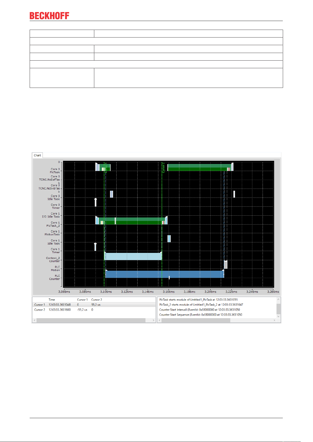
Measuring times
The cursors can be used to precisely determine the execution times of processes or the time of occurrence
of a user event. To do this, move one cursor to a relevant time within the display. The cursor automatically
"latches" to events and displays the events occurring at that time for the active cursor in the cursor window.
In the following figure, this is the application event Counter Start Interval for cursor 1.
To measure the duration of the process "Context_2_Counter", proceed as follows:
1. Create a cursor for the process start or use an existing cursor.
2. Move the cursor to the sequence / interval start marker of the process "Context_2_Counter" so that this
event is displayed in the Event window (see figure above).
3. Proceed accordingly with another cursor and move it to the sequence / interval stop marker of the
process "Context_2_Counter“.
ð The differences between all existing cursors are now displayed in tabular form in the cursor window.
4. Read the value for the cursor you are using directly from the table. For the example shown here, the
execution time is 55.5µs.
Cursor properties
The following properties are available for cursors.
TE101018 Version: 1.3
Page 19
Basic principles
Property Meaning
Cursor info
Color Allows you to change the color of the active cursor.
Text Shows the text displayed at the cursor.
Information
TriggerCursor Activates the property TriggerCursor, which causes a cursor in trigger mode to
remain at the same position in the chart window, rather than being latched to a
point in time (which would cause it to disappears from the display area).
Event window
The Event window shows all events taking place at this time for the active cursor. In the following figure,
these are the following events for cursor 1:
• The PlcTask starts processing of the runtime module Untitled1.
• PlcTask_2 also starts processing of the runtime module Untitled2.
• The Counter application process starts both the sequence and the interval.
TE1010 19Version: 1.3
Page 20
Quick start
4 Quick start
The following chapter is intended to provide an introduction to using the TwinCAT 3 Real-time Monitor.
ü The starting point is a project running on a TwinCAT 3.1 runtime version 3.1.4024.0 or later.
1. Open the Real-time Monitor.
2. Create a new project.
To do this, use the New Project option in the Project menu of the TwinCAT 3 Real-time Monitor. The
project name can be changed via the project properties (see Project node [}29]).
3. Now select the target system that you want to analyze. This is done via the toolbar of the TwinCAT 3
Real-time Monitor.
4. A prompt appears asking whether you want to load the configuration from the target system. Confirm
with "Yes“
ð The active configuration of the target system has been loaded and the contexts are displayed
hierarchically as a tree.
5. Select the tasks that you want displayed in the TwinCAT Real-time Monitor
6. Select the project in the tree view and set the Detailed Logging option in the Properties window to
"True" (see also Marker group element [}31]).
7. If you also want to automatically read the user contexts that may have been set in an application
program, set the AutoCreateUserContexts option to "True" as well.
8. Click the Start Log button in the toolbar of the TwinCAT 3 Real-time Monitor.
TE101020 Version: 1.3
Page 21
ð Recording of the real-time behavior begins.
Quick start
TE1010 21Version: 1.3
Page 22
Reference, user interface
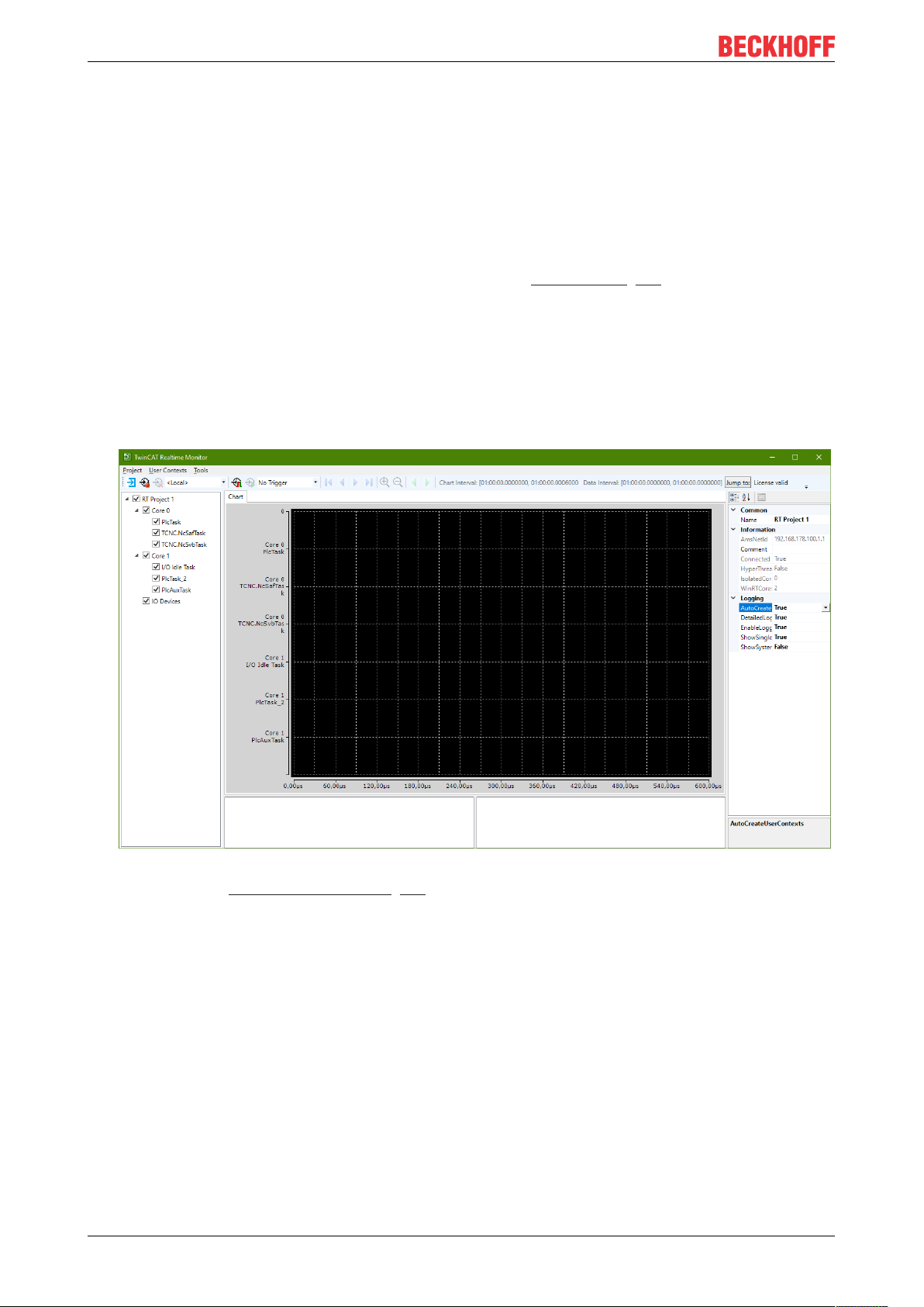
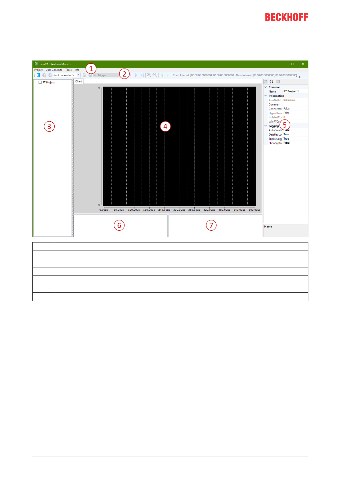
5 Reference, user interface
The user interface of the TwinCAT 3 Real-time Monitor consists of the following components:
1 Menu bar
2 Toolbar
3 Project tree
4 Display window
5 Properties window
6 Cursor window
7 Event window
Project tree: The various time contexts are displayed in the project tree of the TwinCAT 3 Real-time Monitor.
5.1 Menu bar
5.1.1 Project
new Project
Function: This command creates a new TwinCAT 3 Real-time Monitor project.
Call: Menu Project > new Project
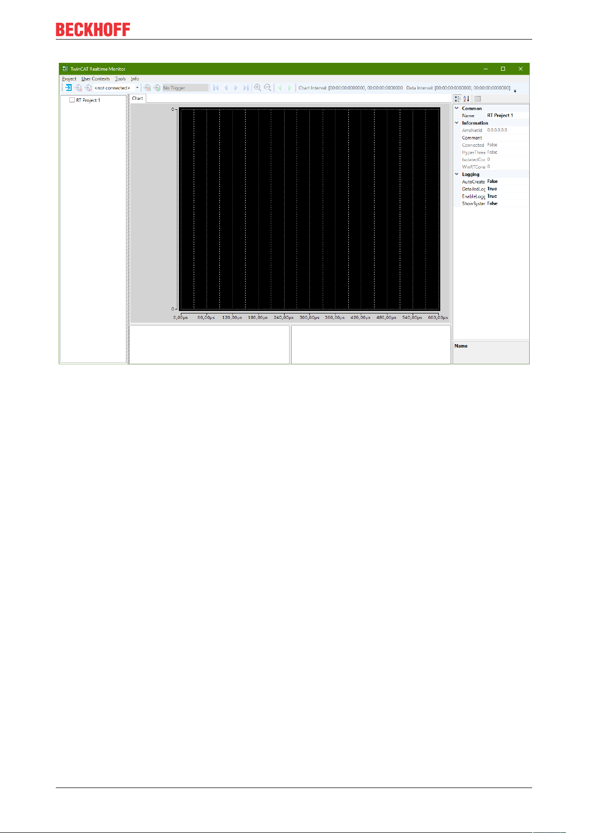
After a new project has been created, the TwinCAT 3 Real-time Monitor appears as follows:
TE101022 Version: 1.3
Page 23
Reference, user interface
open Project
Function: This command opens an existing TwinCAT 3 Real-time Monitor project.
Call: Menu Project > open Project
save Project
Function: This command saves an existing TwinCAT 3 Real-time Monitor project.
Call: Menu Project > save Project
close Project
Function: This command closes an existing TwinCAT 3 Real-time Monitor project.
Call: Menu Project > close Project
5.1.2 User contexts
Import User Contexts
Function: This command imports existing user contexts into a TwinCAT 3 Real-time Monitor project. If the
project contains previously (automatically) found contexts with the same event groups and event IDs, the
user is asked whether these should be replaced by the saved names and settings.
Call: Menu User Contexts > Import User Contexts
Export User Contexts
Function: This command exports existing user contexts from an open TwinCAT 3 Real-time Monitor project.
Call: Menu User Contexts > Export User Contexts
TE1010 23Version: 1.3
Page 24
Reference, user interface
Scan User Contexts
Function: This command scans for existing user contexts and inserts them into a TwinCAT 3 Real-time
Monitor project.
Call: Menu User Contexts > Scan User Contexts
5.1.3 Tools
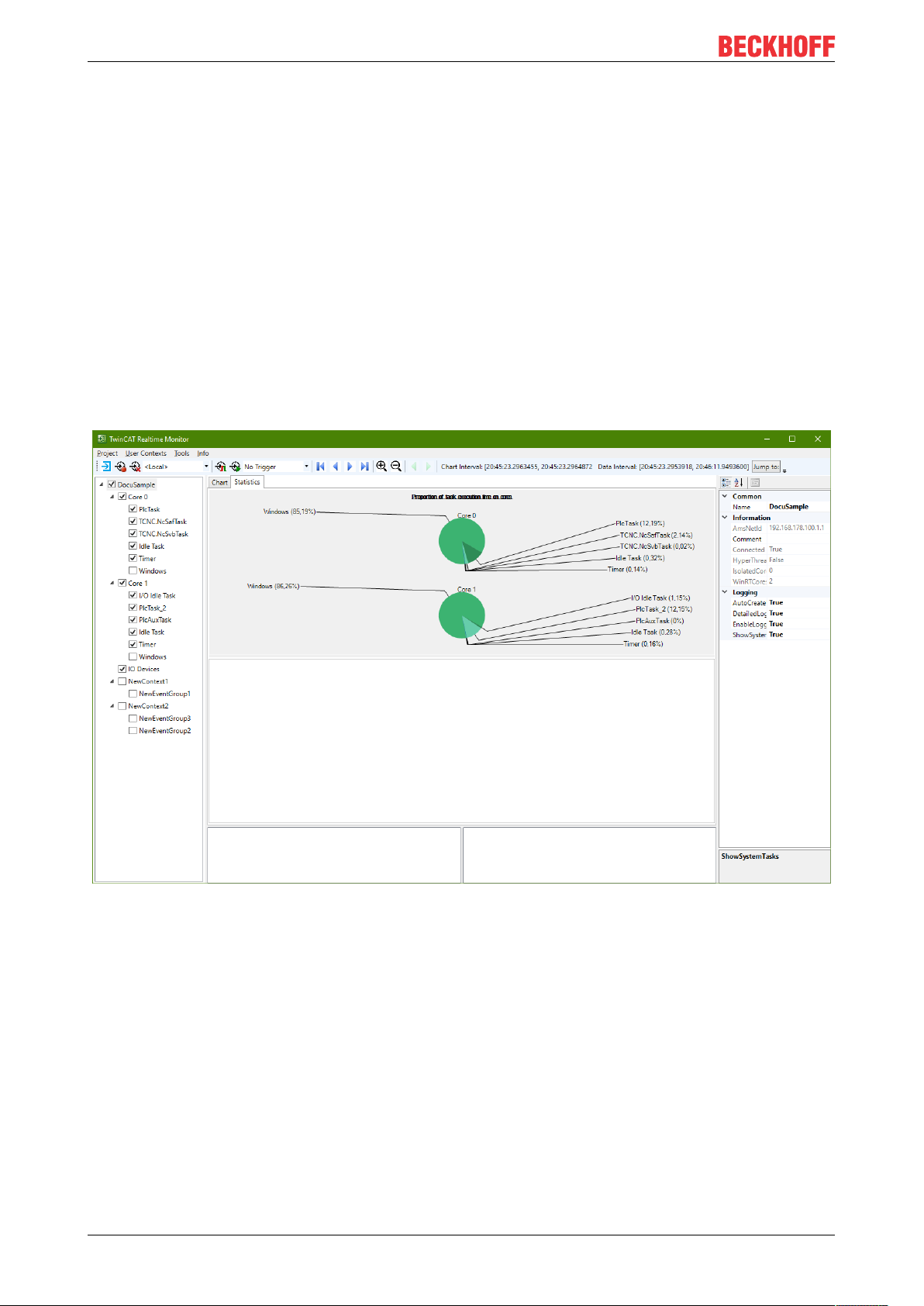
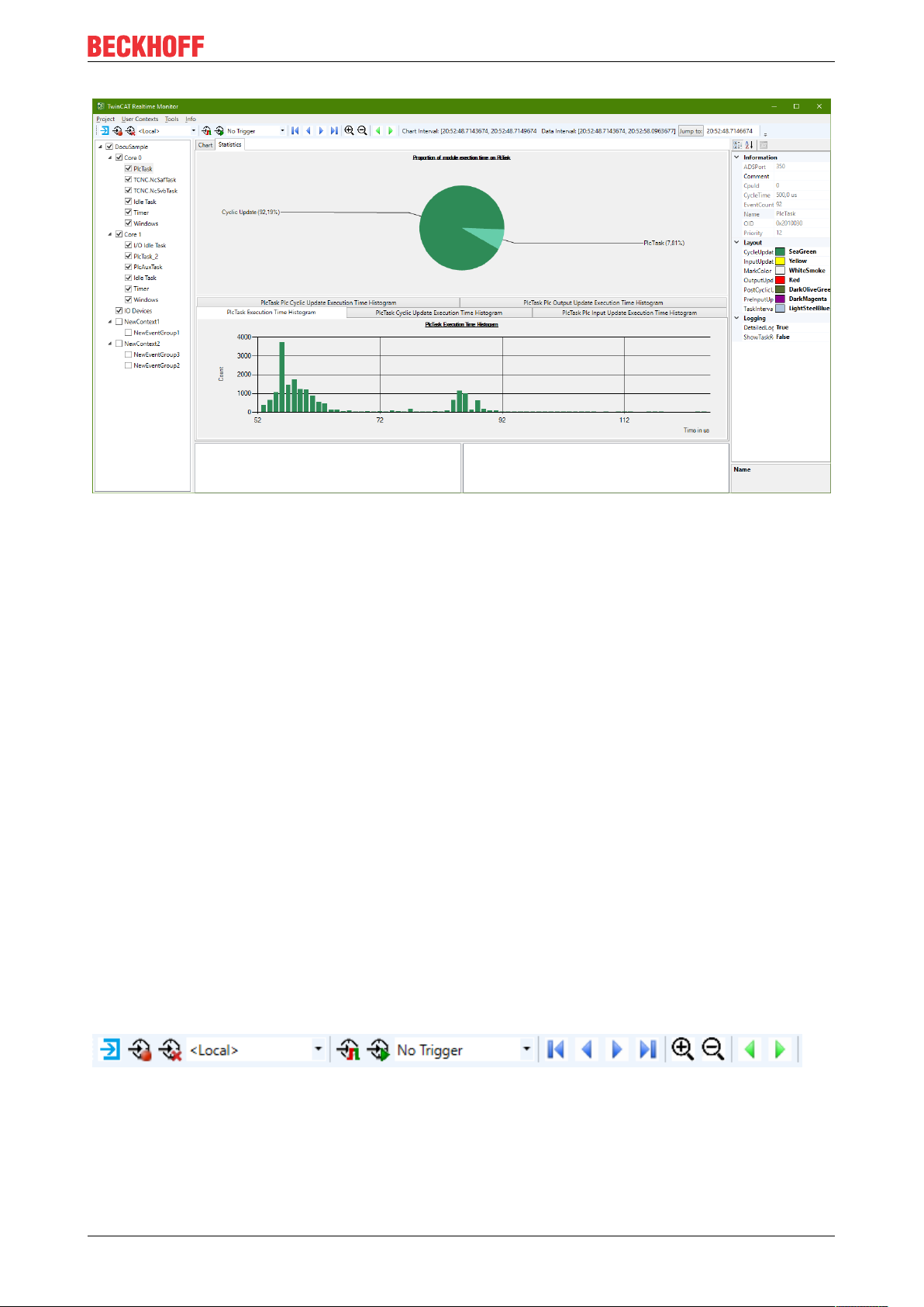
Create Statistics
Function: The command evaluates the markers recorded with the TwinCAT 3 Real-time Monitor and
generates a statistic. This is displayed in the Statistics tab.
Call: Menu Tools > create Statistics
Examples of generated statistics:
TE101024 Version: 1.3
Page 25
Reference, user interface
Export Statistics
Function: The command exports the selected statistics to a CSV file.
Call: Menu Tools > Export Statistics
Set Trigger Prelude
Function: The command determines the prelude of a trigger. The values 1s, 10s, 30s and 1 min are
available.
Call: Menu Tools > Set Trigger Prelude
5.1.4 Info
Real-time Monitor
Function: The command opens a dialog window showing the version number of the installed TwinCAT 3
Real-time Monitor version.
Call: Menu Info > Real-time Monitor
5.2 Toolbar - Real-time Monitor toolbar
The TwinCAT 3 Real-time Monitor toolbar provides the following commands.
TE1010 25Version: 1.3
Page 26

Reference, user interface
Loading the project configuration from the set target system
Start recording
Stop recording
Deleting the displayed data and deleting the recorded data
Choose Target System
Start triggering on live data
Start triggering on recorded data
Selecting a trigger
Manual jump to next trigger event
Manual jump to previous trigger event
Jump to the start of the display
Move the display to the left
Move the display to the right
Jump to the end of the display
Zoom In
Zoom Out
Chart Interval Time interval of the area displayed in the current section
Data Interval Time interval of the recorded data
Jump to the time specified in the selection field after it
Input field for entering a time
5.3 Project tree
The project tree hierarchically displays all marker groups and their assignment to contexts. An entry with the
corresponding task name is automatically created in the tree for the system tasks. System tasks are grouped
into corresponding contexts once they have been assigned to cores.
An entry is also created in the project tree for user-related marker groups. Depending on the call used, the
assignment to contexts in the user program (see FB_RTMon_LogMark [}33] or FB_RTMon_LogMarkBase
[}36]) is made either in relation to the ADS port of the user program or based on a user-defined context ID.
TE101026 Version: 1.3
Page 27

Reference, user interface
The user-related nodes are created either manually by using the context menu entries (see Project tree
[}27]) or automatically if the AutoCreateUserContexts option (see Project node [}29]) is enable or the
User contexts [}24] option is called.
User-related nodes are named according to their Properties page (see Context node [}30] or Marker group
element [}31]).
Context menu entries in the project tree
The following table shows all context menu entries in the project tree (and the node type on which they are
available).
Command Node type Meaning
Add New User Context Project node Adds a user context.
Import User Context Project node Imports a user-related context including all
subelements.
Add New User Group User-related context node Adds a user-related marker group.
Remove User Context User-related context node Deletes a user-related context.
Export User Context User-related context node Exports a user-related context including all
subelements.
Remove User Group User-related marker group
node
Deletes a user-related marker group.
Example:
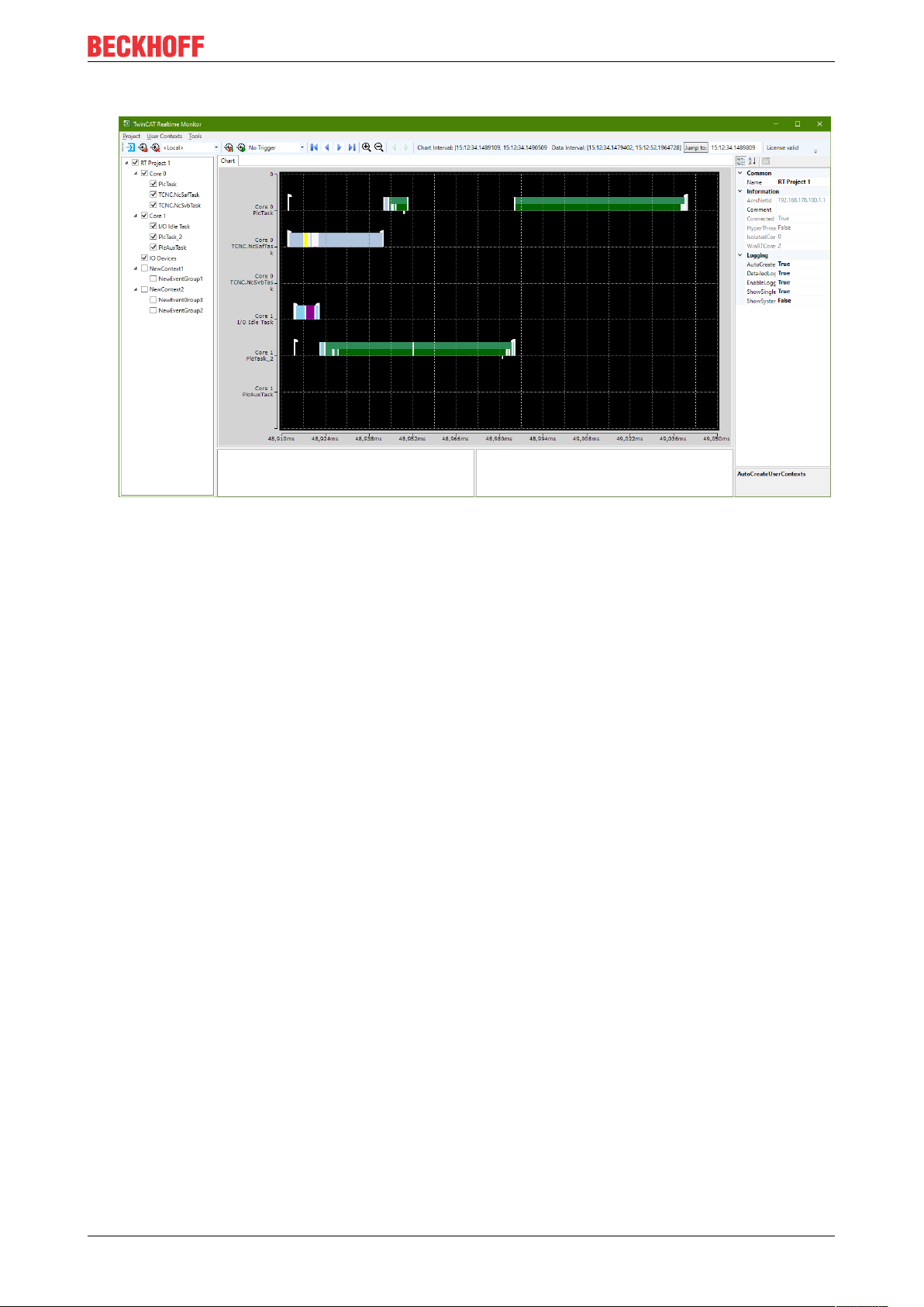
The following figure shows the representation of a project tree as it is automatically generated after the
recording is started (with the AutoCreateUserContexts option activated). In addition to the system tasks
distributed over Core 0 and Core 1, three user-related marker groups are generated, which have not yet
been named here.
TE1010 27Version: 1.3
Page 28

Reference, user interface
5.4 Display window
In the display window (chart) the (time) markers are displayed over time, sorted according to the individual
marker groups.
With the help of the functions in the toolbar (see Toolbar - Real-time Monitor toolbar [}25]) or accordingly
using the mouse or similar operating devices, you can navigate within the display window or enlarge / reduce
the display.
TE101028 Version: 1.3
Page 29

Reference, user interface
Via context menu entries in the display window it is possible to set, delete or move cursors to perform time
measurements or analyses (see Use of cursors [}16]).
5.5 Properties window
The Properties window shows the properties of the currently active (selected) element of the project tree.
The properties listed in the Logging area always apply to all subelements of the tree. The Different
Settings value indicates that the values of the subelements are different. By changing the value, the values
of the subelements are also changed.
5.5.1 Project node
The following settings are available on the project node of the TwinCAT 3 Real-time Monitor:
TE1010 29Version: 1.3
Page 30

Reference, user interface
Property Meaning
Common
Name Name of the project
Information
AmsNetId AmsNetId of the target system
Comment Comment on the project
Connected Connection status to target system
HyperThreading Indicates whether hyperthreading is active
Isolated cores Displays the number of isolated cores used in the project
WinRTCores Displays the number of Windows real-time cores used in
the project
Logging
DetailedLogging Enables detailed logging
EnableLogging Enables logging
ReduceOnZoom Reduces the display depth when zooming out (markers
lying directly adjacent to one another are combined as a
bar) in order to increase performance.
ShowSystemTasks Also shows the system tasks
The properties listed in the Logging area always apply to all subelements. In other words, these properties at
the project level apply to the entire Real-time Monitor project. If the value after one of the properties in the
Logging area is a "Different Settings", this means that the values in the individual sub-nodes differ. Changing
the value at the project level sets the values for all subelements.
5.5.2 Context node
The following settings are available on the context node of the TwinCAT 3 Real-time Monitor. These differ
according to real-time contexts (here the context corresponds to a computer core) and application contexts.
Real-time context:
Property Meaning
Information
BaseTime Base time of the core
Comment Comment
DefaultCore Indicates whether the core is the default core
Id Shows the ID of the core
Name Shows the name of the core
RT_Percentage Shows the set maximum real-time load
Type Shows the type of core (WindowsRT/ isolated core)
Logging
DetailedLogging Enables detailed logging
EnableLogging Turns logging on / off
Application context:
Property Meaning
Information
Comment Comment
ContextId ContextId that was transferred at the markers
Name Name of the context
TE101030 Version: 1.3
Page 31

Reference, user interface
If the function block FB_RTMon_LogMark [}33] is used, the port number of the PLC runtime module is automatically set as ContextId.
5.5.3 Marker group element
The following settings are available on the marker group / process nodes of the TwinCAT 3 Real-time
Monitor. They differ according to real-time tasks and application processes / markers.
Real-time tasks:
Property Meaning
Information
ADSPort ADS port of the task
Comment Comment
CpuId CpuId on which the task is executed
CycleTime Task cycle time
EventCount Number of executions (within the recording time)
Name Name of the task
OID ObjectId of the task
Priority Set priority
Layout
CycleUdateColor Color of the CycleUpdate of a task (default: green)
InputUpdateColor Color of the InputUpdate of a task (default: yellow)
MarkColor Marker color (default: white)
OutputUpdateColor Color of the output update of the task (default: red)
PostCyclicUpdateColor Color of the PostCyclicUpdate of the task (default: dark green)
PreInputUpdateColor Color of the PreInputUpdate of the task (default: magenta)
TaskIntervalColor Color of the task interval marker (default: light blue)
Logging
DetailedLogging Activate detailed logging
ShowTaskReference Displaying the task references
User processes:
Property Meaning
Information
Comment Comment
EventCount Number of executions (within the recording time)
GroupId ID of the marker group / process
Name Name of the process to be displayed
Layout
EventIntervalColor Color for the interval / active execution of the process (default: blue)
MarkColor Color of the markers (default: white)
Logging
ShowSingleMarker Enables the display of individual markers
ShowTaskReference Enables the display of task references (assignment of process markers to
real-time tasks by dashed lines)
TE1010 31Version: 1.3
Page 32

Reference, user interface
5.6 Cursor window
All cursors that were created are displayed in the cursor window.
Double-clicking a cursor causes the display within the chart to jump to the exact position where the cursor is
positioned. The cursor is centered in the display area.
The selected cursor can be deleted using the context menu entry Remove Cursor.
The use of cursors is described in detail under Use of cursors [}16].
5.7 Event window
The Event window shows all events taking place at this time for the active cursor. In the following figure,
these are the following events for cursor 1:
• The PlcTask starts processing of the runtime module Untitled1.
• PlcTask_2 also starts processing of the runtime module Untitled1.
• The Counter application process starts both the sequence and the interval.
TE101032 Version: 1.3
Page 33
PLC API
6 PLC API
6.1 Function blocks
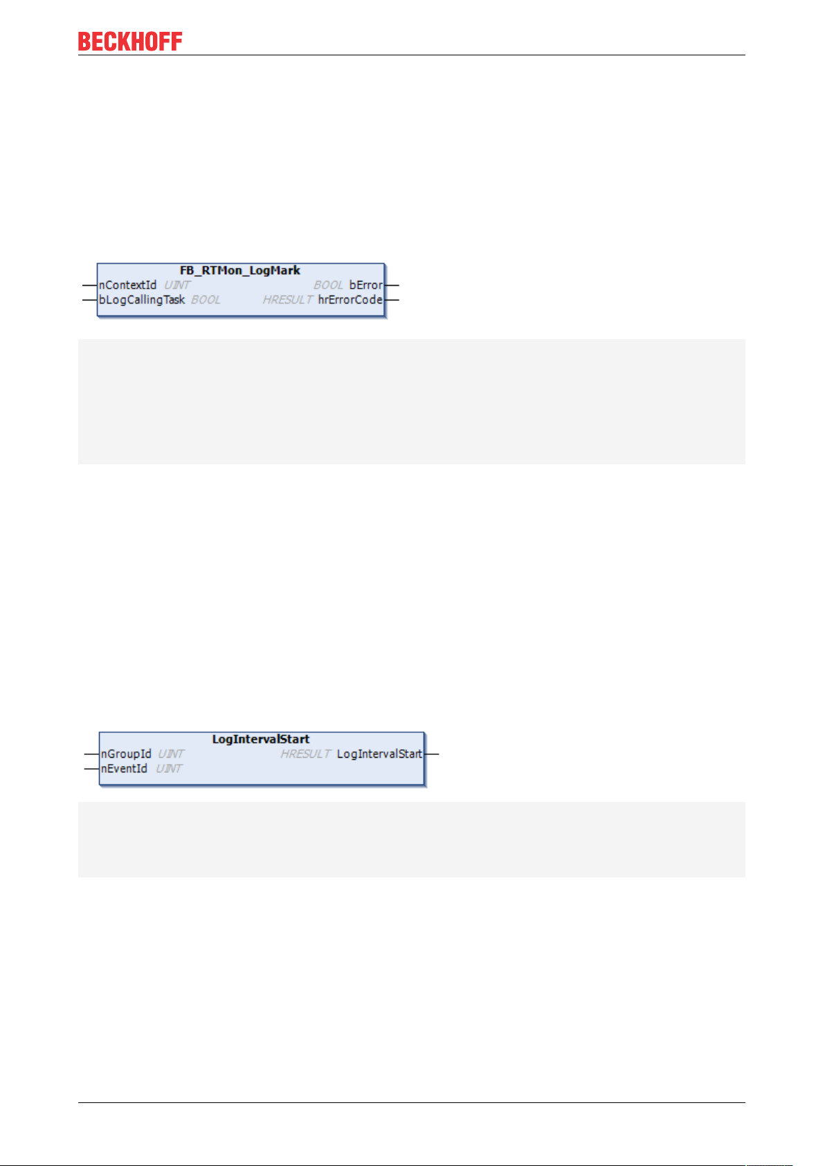
6.1.1 FB_RTMon_LogMark
FUNCTION_BLOCK FB_RTMon_LogMark
VAR_INPUT
nContextId: UINT := TwinCAT_SystemInfoVarList._AppInfo.AdsPort;
bLogCallingTask: BOOL:= TRUE; // specifies whether a reference to the calling task should be
set with each mark
END_VAR
VAR_OUTPUT
bError: BOOL; // TRUE if an error occurred
hrErrorCode: HRESULT; // outputs the error code which occurred
END_VAR
Description:
The FB_RTMon_LogMark is an extended function block that enables the setting of "simple" (time) markers.
For "simple" markers, the context of the calling user program is used automatically. The possible marker
types (sequence start & stop, interval start & stop or marker) are made available via individual methods. Only
the marker ID (marker group) must be transferred by the user. This is used to identify the process to be
displayed.
Optionally, an event ID is also available in which the user can transfer a user record (e.g. status of a state
machine, error message …)
6.1.1.1 LogIntervalStart
// Starts logging interval
METHOD LogIntervalStart : HRESULT
VAR_INPUT
nGroupId: UINT; // Defines the group to which the interval belongs
nEventId: UINT; // Set to distinguish different events inside the group
END_VAR
Description
The method creates a marker with an interval start for the transferred marker ID.
Parameter:
nGroupId: Marker ID (marker group) for which the marker is to be written.
nEventId: optional EventId.
TE1010 33Version: 1.3
Page 34
PLC API
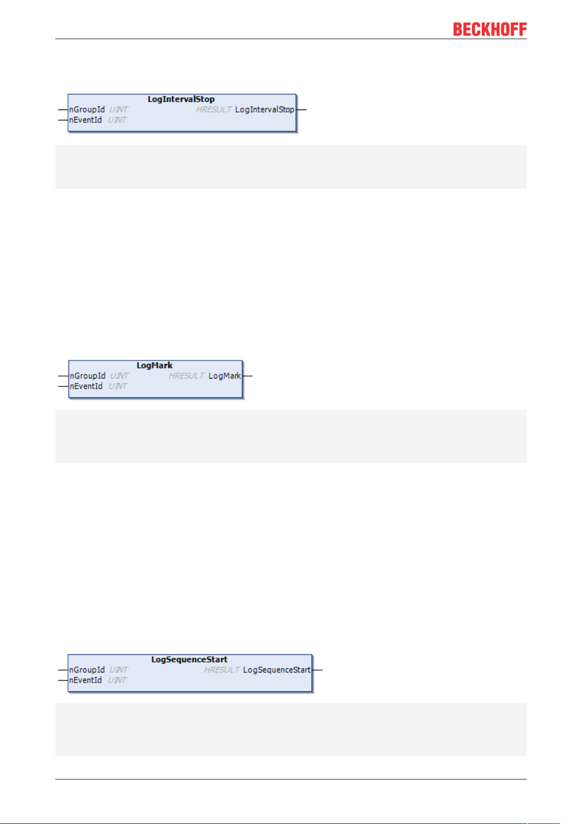
6.1.1.2 LogIntervalStop
METHOD LogIntervalStop : HRESULT
VAR_INPUT
nGroupId: UINT; // Defines the group to which the interval belongs
nEventId: UINT; // Set to distinguish different events inside the group
END_VAR
Description
The method creates a marker with an interval stop for the transferred marker ID.
Parameter:
nGroupId: Marker ID (marker group) for which the marker is to be written.
nEventId: optional EventId.
6.1.1.3 LogMark
// Logs a mark without start/stop
METHOD LogMark : HRESULT
VAR_INPUT
nGroupId: UINT; // Defines the group to which the mark belongs
nEventId: UINT; // Set to distinguish different events inside the group
END_VAR
Description
The method creates a marker for the marker ID that was transferred. Optionally, the event ID can be used to
distinguish between different user events or to display additional data (formatted as UINT) in the TwinCAT 3
Real-time Monitor display.
Parameter:
nGroupId: Marker ID (marker group) for which the marker is to be written.
nEventId: optional EventId.
6.1.1.4 LogSequenceStart
// Starts logging sequence
METHOD LogSequenceStart : HRESULT
VAR_INPUT
nGroupId: UINT; // Defines the group to which the sequence belongs
nEventId: UINT; // Set to distinguish different events inside the group
END_VAR
TE101034 Version: 1.3
Page 35

Description
The method creates a marker with a sequence start for the marker ID that was transferred.
Parameter:
nGroupId: Marker ID (marker group) for which the marker is to be written.
nEventId: optional EventId.
6.1.1.5 LogSequenceStop
// Stops logging sequence
METHOD LogSequenceStop : HRESULT
VAR_INPUT
nGroupId: UINT; // Defines the group to which the sequence belongs
nEventId: UINT; // Set to distinguish different events inside the group
END_VAR
PLC API
Description
The method creates a marker with a sequence stop for the marker ID that was transferred.
Parameter:
nGroupId: Marker ID (marker group) for which the marker is to be written.
nEventId: optional EventId.
6.1.1.6 LogStart
// Starts logging sequence and interval
METHOD LogStart : HRESULT
VAR_INPUT
nGroupId: UINT; // Defines the group to which the sequence and intervall belong
nEventId: UINT; // Set to distinguish different events inside the group
END_VAR
Description
The method creates a marker with a sequence and interval start for the transferred marker ID.
Thus this marker represents the time of a process at which it is immediately active / started.
Parameter:
nGroupId: Marker ID (marker group) for which the marker is to be written.
nEventId: optional EventId.
TE1010 35Version: 1.3
Page 36
PLC API
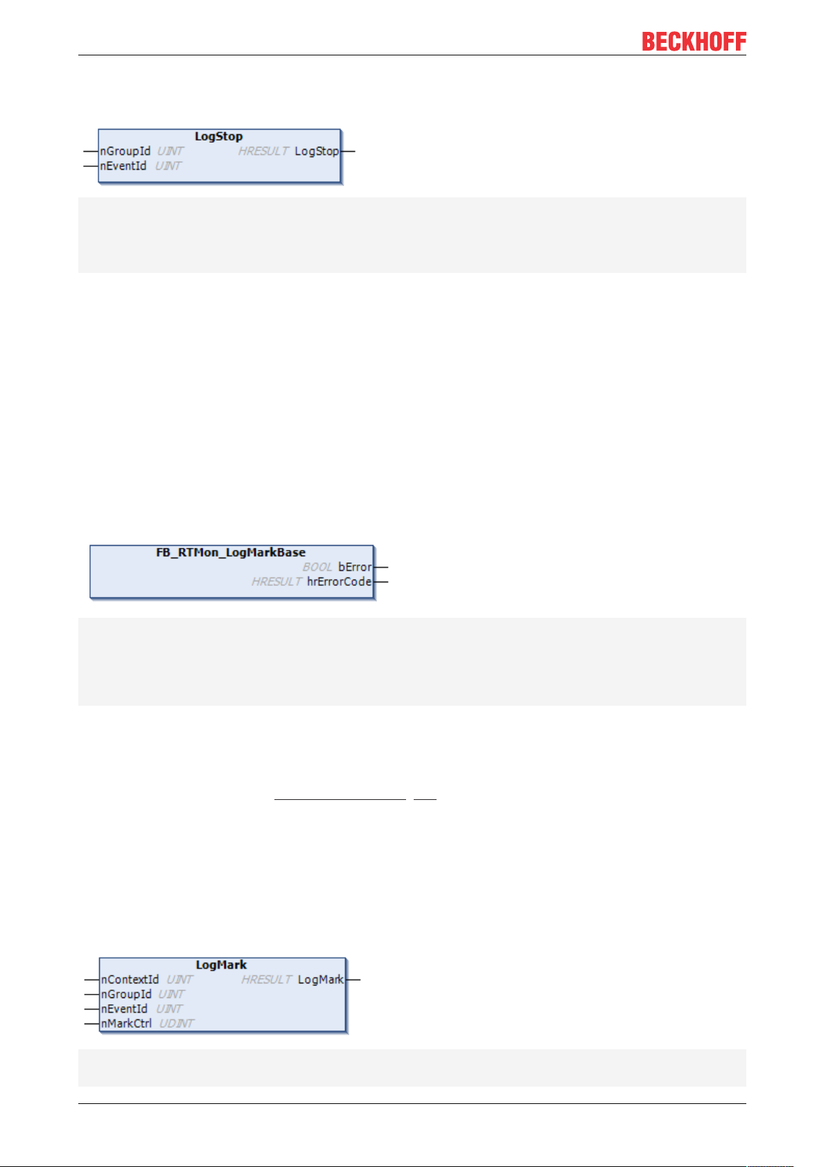
6.1.1.7 LogStop
// Stops logging sequence and interval
METHOD LogStop : HRESULT
VAR_INPUT
nGroupId: UINT; // Defines the group to which the sequence and intervall belong
nEventId: UINT; // Set to distinguish different events inside the group
END_VAR
Description
The method creates a marker with a sequence and interval stop for the transferred marker ID.
Thus, this marker represents the point in time of a process at which it is terminated directly.
Parameter:
nGroupId: Marker ID (marker group) for which the marker is to be written.
nEventId: optional EventId.
6.1.2 FB_RTMon_LogMarkBase
FUNCTION_BLOCK FB_RTMon_LogMarkBase
VAR_INPUT
END_VAR
VAR_OUTPUT
bError: BOOL; // TRUE if an error occurred
hrErrorCode: HRESULT; // outputs the error code which occurred
END_VAR
Description:
FB_RTMon_LogMarkBase is a basic function block that enables the setting of (time) markers.
In contrast to the function block FB_RTMon_LogMark [}33], the context ID itself must be transferred here.
This makes it possible to group the processes to be displayed (for example, by process type or functional
unit).
Optionally, an event ID is also available in which the user can transfer a user record (e.g. status of a state
machine, error message).
6.1.2.1 LogMark
METHOD LogMark : HRESULT
VAR_INPUT
nContextId: UINT; // defines the context
TE101036 Version: 1.3
Page 37
PLC API
nGroupId: UINT; // defines the group inside the context
nEventId: UINT; // defines the specific event inside the group
nMarkCtrl: UDINT; // mask for mark options (listed in TcMarkOption)
END_VAR
Description
The method creates a marker for the transferred marker group ID. The marker type is transferred using the
parameter nMarkCtrl (see TcMarkOption [}38]).
Optionally, the event ID can be used to distinguish between different user events or to display additional data
(formatted as UINT) in the TwinCAT 3 Real-time Monitor display.
Parameter:
nContextId: defines the context ID under which the marker is to be grouped in the TwinCAT 3 Real-time
Monitor.
nGroupId: Marker ID (marker group) for which the marker is to be written.
nEventId: optional EventId.
nMarkCtrl: defines the marker type.
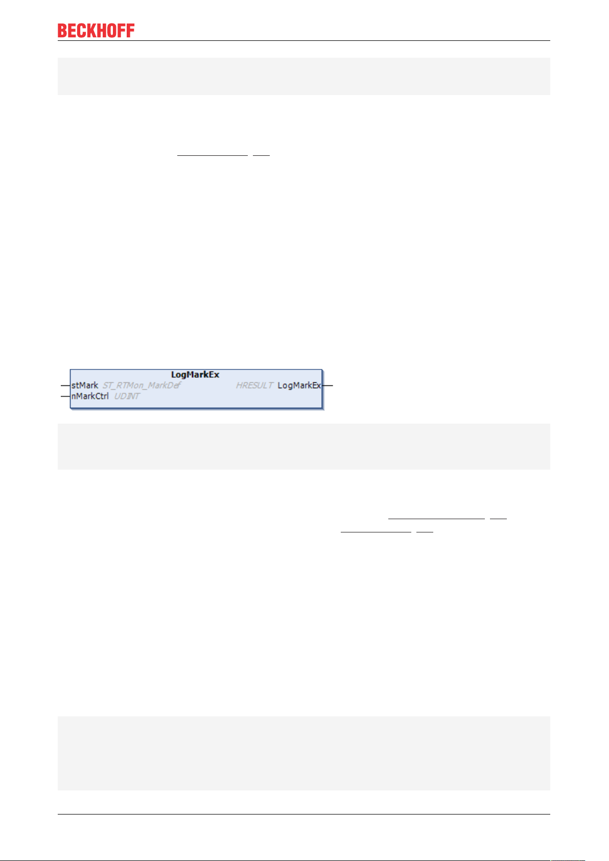
6.1.2.2 LogMarkEx
METHOD LogMarkEx: HRESULT
VAR_INPUT
stMark: ST_RTMon_MarkDef;
nMarkCtrl: UDINT; // mask for mark options (listed in TcMarkOption)
END_VAR
Description
The method creates a marker. The marker is defined using the data type ST_RTMon_MarkDef [}37]. The
marker type is transferred using the parameter nMarkCtrl (see TcMarkOption [}38]).
Parameter:
stMark: Transfer parameter for a defined marker that is to be written.
nMarkCtrl: defines the marker type.
6.2 Data types
6.2.1 ST_RTMon_MarkDef
Data type that represents a marker.
// defines a mark
TYPE ST_RTMon_MarkDef:
STRUCT
nContextId: UINT; // defines the context
nGroupId : UINT; // defines the group inside the context
nEventId : UINT; // defines the specific event inside the group
END_STRUCT
END_TYPE
TE1010 37Version: 1.3
Page 38

PLC API
Description
Using this data type, it is possible to define a generic marker (without type). This is then transferred in the
method LogMarkEx [}37] of the function block FB_RTMon_LogMarkBase [}36] in addition to the marker type.
nContextId: Using the ContextId, marker groups, i.e. processes to be displayed, can be grouped (e.g. by
process type or functional unit).
nGroupId: Defines the process/ process event to be displayed.
nEventId: Optional user record. This can be used, for example, to display the status of a state machine or
error codes in the TwinCAT 3 Real-time Monitor.
Both the ContextId and the GroupId can be given names in the TwinCAT 3 Real-time Monitor.
These can be exported or imported using the User contexts [}23] or User contexts [}23] functions,
so that they are available for a further recording.
6.3 Global constants
6.3.1 TcMarkOption
The constants in this global variable list define the possible marker types (see Display in the Real-time
Monitor [}12]).
VAR_GLOBAL CONSTANT
Start: UDINT := 16#E0000000;
Stop: UDINT := 16#C0000000;
SequenceStart: UDINT := 16#A0000000;
SequenceStop: UDINT := 16#80000000;
IntervalStart: UDINT := 16#60000000;
IntervalStop: UDINT := 16#40000000;
RefToCaller: UDINT := 16#08000000; // reference to caller
END_VAR
In addition to the marker types, the option RefToCaller is defined, which enables the task references to be
displayed in the TwinCAT3 Real-Time Monitor. If this option is activated it must be ORed with the desired
marker type.
Sample:
fbLogMark.LogMarkEx(markCounter, TcMarkOption.Start OR TcMarkOption.RefToCaller);
The sample shows the setting of a marker, "markCounter", with the marker type "Start" and the option
"RefToCaller".
The option Show Task Reference (see Marker group element [}31]) must be activated if the task
references are to be displayed in the TwinCAT3 Real-Time Monitor.
Also see about this
2 FB_RTMon_LogMarkBase [}36]
TE101038 Version: 1.3
Page 39

C++ API
7 C++ API
7.1 Data types
7.1.1 TcMark16
Data type that represents a marker.
typedef struct {
USHORT ContextId;
USHORT GroupId;
USHORT EventId;
} TcMark16;
Description:
Using this data type, it is possible to define a generic marker (without type).
ContextId: Using the ContextId, marker groups, i.e. processes to be displayed, can be grouped (e.g. by
process type or functional unit).
GroupId: Defines the process/ process event to be displayed.
EventId: Optional user record. This can be used, for example, to display the status of a state machine or
error codes in the TwinCAT 3 Real-time Monitor.
Both the ContextId and the GroupId can be given names in the TwinCAT 3 Real-time Monitor.
These can be exported or imported using the User contexts [}23] or User contexts [}23] functions,
so that they are available for a further recording.
7.2 Classes
7.2.1 CTcLogMark
CTcLogMark(USHORT nContextId, ITComObjectServer* ipSrv = NULL);
Description:
The class CTcLogMark is a C++ class that makes it possible to set (time) markers from C++ application code
so that they can be displayed with the TwinCAT 3 Real-time Monitor.
7.2.1.1 LogIntervalStart
virtual HRESULT LogIntervalStart(USHORT GroupId, USHORT EventId);
Description:
The method creates a marker with an interval start for the transferred marker ID.
Parameter:
GroupId: Marker ID (marker group) for which the marker is to be written.
EventId: optional EventId.
TE1010 39Version: 1.3
Page 40

C++ API
7.2.1.2 LogIntervalStop
virtual HRESULT LogIntervalStop(USHORT GroupId, USHORT EventId);
Description:
The method creates a marker with an interval stop for the transferred marker ID.
7.2.1.3 LogMark
virtual HRESULT LogMark(USHORT GroupId, USHORT EventId, ULONG CtrlId);
Description:
The method creates a marker for the transferred marker group ID. The marker type is determined using the
constants from TcLogMark.h (see Constants [}41]).
Optionally, the event ID can be used to distinguish between different user events or to display additional data
(formatted as USHORT) in the TwinCAT 3 Real-time Monitor display.
Also see about this
2 TcMarkOption [}38]
7.2.1.4 LogMarkEx
virtual HRESULT LogMarkEx(TcMark16* pMark, ULONG CtrlId);
Description
The method creates a marker. The marker is defined using the data type TcMark16 [}39]. The marker type
is determined using the constants from TcLogMark.h (see Constants [}41]).
Also see about this
2 ST_RTMon_MarkDef [}37]
7.2.1.5 LogSequenceStart
virtual HRESULT LogSequenceStart(USHORT GroupId, USHORT EventId);
Description:
The method creates a marker with a sequence start for the marker ID that was transferred.
7.2.1.6 LogSequenceStop
virtual HRESULT LogSequenceStop(USHORT GroupId, USHORT EventId);
Description:
The method creates a marker with a sequence stop for the marker ID that was transferred.
7.2.1.7 LogStart
virtual HRESULT LogStart(USHORT GroupId, USHORT EventId);
TE101040 Version: 1.3
Page 41

Description:
The method creates a marker with a sequence and interval start for the transferred marker ID.
Thus this marker represents the time of a process at which it is immediately active / started.
7.2.1.8 LogStop
virtual HRESULT LogStop(USHORT GroupId, USHORT EventId);
Description
The method creates a marker with a sequence and interval stop for the transferred marker ID.
Thus, this marker represents the point in time of a process at which it is terminated directly.
7.2.1.9 SetContextId
virtual void SetContextId(USHORT nContextId);
Description:
C++ API
This method sets the context ID used.
7.2.1.10 InitLogMark
virtual HRESULT InitLogMark(ITComObjectServer* ipSrv);
Description:
Initializes the instance of the CTcLog marker class.
Parameter:
ipSrv: Interface pointer to the TcObjectServer.
7.2.1.11 ReleaseLogMark
virtual HRESULT ReleaseLogMark();
Description:
Releases the resources of the instance of the CTcLogMark class.
7.3 Constants
These constants - defined in TcLogMark.h - define the possible marker types [}12].
#define TCMARK_START 0xE0000000
#define TCMARK_STOP 0xC0000000
#define TCMARK_SEQ_START 0xA0000000
#define TCMARK_SEQ_STOP 0x80000000
#define TCMARK_IVAL_START 0x60000000
#define TCMARK_IVAL_STOP 0x40000000
#define TCMARK_REF_CALLER 0x08000000
TE1010 41Version: 1.3
Page 42

Page 43

More Information:
www.beckhoff.com/te1010
Beckhoff Automation GmbH & Co. KG
Hülshorstweg 20
33415 Verl
Germany
Phone: +49 5246 9630
info@beckhoff.com
www.beckhoff.com
 Loading...