

Page 1
Documentation | EN
SCT2xxx
Ring-type current transformer
2021-04-12 | Version: 1.3
Page 2

Page 3

Table of contents
Table of contents
1 Foreword ....................................................................................................................................................5
1.1 Notes on the documentation..............................................................................................................5
1.2 Safety instructions .............................................................................................................................6
2 Product overview.......................................................................................................................................8
2.1 Introduction........................................................................................................................................8
2.2 Basics current transformers...............................................................................................................9
2.3 Product categories – SCTxxxx current transformer.........................................................................12
2.4 Notes on class accuracy SCT transformers ....................................................................................20
3 Technical data..........................................................................................................................................21
3.1 SCT21xx | Ring-type current transformer, size 1.............................................................................21
3.1.1 SCT21xx | General .......................................................................................................... 21
3.1.2 SCT2111 | Ring-type current transformer for primary currents 0...60 A to 0...500 A, accu-
racy class 1, size 1 .......................................................................................................... 23
3.1.3 SCT2121 | Ring-type current transformer for primary currents 0…125 A to 0…600 A, ac-
curacy class 0.5, size 1.................................................................................................... 24
3.2 SCT22xx | Ring-type current transformer, size 2.............................................................................25
3.2.1 SCT22xx | General .......................................................................................................... 25
3.2.2 SCT2211 | Ring-type current transformer for primary currents 0...600 A/0...750 A, accu-
racy class 1, size 2 .......................................................................................................... 27
3.2.3 SCT2221 | Ring-type current transformer for primary currents 0…600 A/0…750 A, accu-
racy class 0.5, size 2 ....................................................................................................... 28
3.3 SCT23xx | Ring-type current transformer, size 3.............................................................................29
3.3.1 SCT23xx | General .......................................................................................................... 29
3.3.2 SCT2311 | Ring-type current transformer for primary currents 0…800 A/0…1000 A, accu-
racy class 1, size 3 .......................................................................................................... 31
3.3.3 SCT2321 | Ring-type current transformer for primary currents 0…800 A/0…1000 A, accu-
racy class 0.5, size 3 ....................................................................................................... 32
3.4 SCT24xx | Ring-type current transformer, size 4.............................................................................33
3.4.1 SCT24xx | General .......................................................................................................... 33
3.4.2 SCT2411 | Ring-type current transformer for primary currents 0…1250 A/0…1500 A, ac-
curacy class 1, size 4....................................................................................................... 35
3.4.3 SCT2421 | Ring-type current transformer for primary currents 0…1250 A/0…1500 A, ac-
curacy class 0.5, size 4.................................................................................................... 36
3.5 SCT25xx | Ring-type current transformer, size 5.............................................................................37
3.5.1 SCT25xx | General .......................................................................................................... 37
3.5.2 SCT2515 | Ring-type current transformers for primary current 0…2000 A, accuracy class
1, size 5 ........................................................................................................................... 39
3.5.3 SCT2525 | Ring-type current transformers for primary current 0…2000 A, accuracy class
0.5, size 5 ........................................................................................................................ 40
3.6 SCT26xx | Ring-type current transformer, size 6.............................................................................41
3.6.1 SCT26xx | General .......................................................................................................... 41
3.6.2 SCT2615 | Ring-type current transformers for primary current 0…2500 A, accuracy class
1, size 6 ........................................................................................................................... 43
3.6.3 SCT2625 | Ring-type current transformers for primary current 0...2500 A, accuracy class
0.5, size 6 ........................................................................................................................ 44
4 Commissioning........................................................................................................................................45
SCT2xxx 3Version: 1.3
Page 4

Table of contents
5 Application example................................................................................................................................50
5.1 Power measurement at a machine..................................................................................................50
6 Appendix ..................................................................................................................................................52
6.1 Documentation issue status ............................................................................................................52
6.2 UL notes ..........................................................................................................................................53
6.3 Support and Service ........................................................................................................................54
SCT2xxx4 Version: 1.3
Page 5

Foreword
1 Foreword
1.1 Notes on the documentation
Copyright
© Beckhoff Automation GmbH & Co. KG, Germany.
The reproduction, distribution and utilization of this document as well as the communication of its contents to
others without express authorization are prohibited.
Offenders will be held liable for the payment of damages. All rights reserved in the event of the grant of a
patent, utility model or design.
Disclaimer
The documentation has been prepared with care. The products described are, however, constantly under
development.
We reserve the right to revise and change the documentation at any time and without prior announcement.
No claims for the modification of products that have already been supplied may be made on the basis of the
data, diagrams and descriptions in this documentation.
EtherCAT® is registered trademark and patented technology, licensed by Beckhoff Automation GmbH,
Germany.
Trademarks
Beckhoff®, TwinCAT®, EtherCAT®, EtherCATG®, EtherCATG10®, EtherCATP®, SafetyoverEtherCAT®,
TwinSAFE®, XFC®, XTS® and XPlanar® are registered trademarks of and licensed by Beckhoff Automation
GmbH. Other designations used in this publication may be trademarks whose use by third parties for their
own purposes could violate the rights of the owners.
Patent Pending
The EtherCAT Technology is covered, including but not limited to the following patent applications and
patents: EP1590927, EP1789857, EP1456722, EP2137893, DE102015105702 with corresponding
applications or registrations in various other countries.
Intended audience
This description is only intended for the use of trained specialists in control and automation engineering who
are familiar with the applicable national standards.
It is essential that the documentation and the following notes and explanations are followed when installing
and commissioning these components.
It is the duty of the technical personnel to use the documentation published at the respective time of each
installation and commissioning.
The responsible staff must ensure that the application or use of the products described satisfy all the
requirements for safety, including all the relevant laws, regulations, guidelines and standards.
SCT2xxx 5Version: 1.3
Page 6
Foreword
1.2 Safety instructions
Description of instructions
In this documentation the following instructions are used.
These instructions must be read carefully and followed without fail!
DANGER
Serious risk of injury!
Failure to follow this safety instruction directly endangers the life and health of persons.
WARNING
Risk of injury!
Failure to follow this safety instruction endangers the life and health of persons.
CAUTION
Personal injuries!
Failure to follow this safety instruction can lead to injuries to persons.
NOTE
Damage to environment/equipment or data loss
Failure to follow this instruction can lead to environmental damage, equipment damage or data loss.
Tip or pointer
This symbol indicates information that contributes to better understanding.
Exclusion of liability
All the components are supplied in particular hardware and software configurations appropriate for the
application. Modifications to hardware or software configurations other than those described in the
documentation are not permitted, and nullify the liability of Beckhoff Automation GmbH & Co. KG.
Personnel qualification
This description is only intended for trained specialists in control, automation and drive engineering who are
familiar with the applicable national standards.
Intended use
If the equipment is used in a manner not specified by the manufacturer, the protection provided by the
equipment may be impaired
Safety regulations
Please note the following safety instructions and explanations!
Product-specific safety instructions can be found on following pages or in the areas mounting, wiring,
commissioning etc.
Current transformer safety instructions
The following points must be noted:
• The applicable laws, standards and regulations.
• The state of the art at the time of installation.
• The technical rules.
SCT2xxx6 Version: 1.3
Page 7

Foreword
• The operating instructions.
• The fact that operating instructions can only list general regulations and that these regulations must be
followed.
• Check the device carefully for transport damage prior to commissioning. The device must not be put
into operation if it is mechanically damaged.
• The devices described are intended for installation by qualified electricians and may only be installed in
electrical plant rooms or in closed housings. Any other use or the disregard of these application notes
will result in the loss of the warranty/guarantee.
• The devices may only be installed in dry indoor rooms.
• Do not mount on highly flammable materials.
• Operation with a higher current than the rated current specified on the name plate can lead to
overheating of the current transformer and thus to burns.
SCT2xxx 7Version: 1.3
Page 8
Product overview
2 Product overview
2.1 Introduction
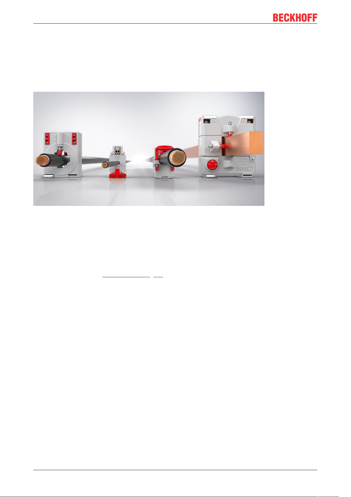
SCTxxxx | Current transformers (CT) for energy measurement
Fig.1: SCT current transformers
With its SCT current transformers, Beckhoff makes it possible to implement reliable power sensor technology
in the field, which is directly integrated into the PC-based control system. Users can select from two device
concepts, each with various designs and performance categories that are highly scalable and therefore
suitable for any application. The SCT portfolio is extremely broad-based, ranging from low-cost 3-phase CT
sets for building technology to standard industrial transformers for machines through to solutions for
inspection and test stands with extra-high accuracy requirements.
The choice of the suitable product category [}12] depends on the type of use. While ring-type CTs are
predestined for cost-effective and accurate data acquisition in new installations, split-core CTs provide the
ideal solution for retrofit solutions due to their easy installation.
SCT2xxx8 Version: 1.3
Page 9
Product overview
2.2 Basics current transformers
Function and design
A current transformer is a transforming device that transforms an input current into a processable current
signal at the output. A current transformer is mainly used to transform currents of large magnitudes to directly
measurable, smaller values in the milliampere or small ampere range. With a classic current transformer, the
input current is proportional to the output current. Due to the physical principle and the mechanical
construction, the current signal is transmitted galvanically isolated to the evaluation electronics.
A current transformer basically consists of a small number of windings on the primary side and a larger
number of windings on the secondary side. The current to be converted flows through the primary side. The
windings are usually wound on an alternating magnetic ferrite ring core.
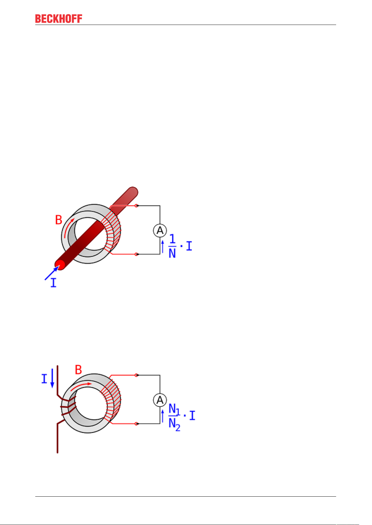
A typical transformer type is the ring core or ring-type current transformer. The current rail or current-carrying
cable is often used as the primary winding, which is guided through the toroidal core of the transformer.
Thus, the rail or line forms the primary winding with one turn. The secondary winding is located on the ring
core. The transformation is determined by the ratio of the number of primary and secondary windings. The
classic structure of a ring-type current transformer is shown in the following figure.
Fig.2: Principle ring-type current transformer
Another classic type is the coiled current transformer. In this type of transformer, the primary winding is a
current-carrying wire which is wound around the ring core on the primary side. In this case, the primary
winding number is >1, but smaller than the secondary winding number. The principle is shown in the
following figure
Fig.3: Principle coil current transformer
SCT2xxx 9Version: 1.3
Page 10

Product overview
WARNING
Dangerous voltages with secondary side not connected
The secondary winding must be connected to a current measuring device or short-circuited, otherwise high
core losses or dangerous voltages may occur on the secondary side. Before replacing the measuring electronics in the secondary circuit, the current transformer must therefore be short-circuited at its secondary
terminals.
Grounding of secondary terminals
According to DIN VDE 0141 (01/2000) paragraph 5.3.4, current and voltage transformers for nominal voltages from Um = 3.6 kV must be grounded on the secondary side. For low voltages (Um ≤
1.2 kV), grounding is not required if the transformer housings do not have any metal surfaces with
large contact areas.
Characteristic values and calculation
In principle, the construction, and thus also the calculation, correspond to a normal transformer. The basic
relationship between input and output current is determined by the ratio of the number of turns N of the
primary and secondary sides. An important characteristic value in the design of a current transformer is
therefore the transformer ratio.
I
= N1/N2 * I
Out
In
SCT2xxx10 Version: 1.3
Page 11

Product overview
Technical terms of current transformers
Term Explanation
Primary rated current Ipr
Value of the rated current on the primary side.
(alternative formula symbol IN)
Secondary rated current I
Rated power S
r
sr
Value of the rated current on the secondary side.
Value of apparent power (in [VA]) that the transformer can deliver
to the secondary circuit at secondary rated current and rated load.
Rated frequency f
R
Value of the rated frequency.
Accuracy class Indication that the measurement deviations are within specified
limits under prescribed application conditions.
Rated insulation level U
m
Maximum voltage; RMS value of the highest conductor-toconductor voltage for which a instrument transformer is rated with
respect to its insulation.
Specified is the value of the rated insulation level in three values:
1. maximum value of the conductor-to-conductor voltage for which
the isolation of the transducers is rated;
2. value of the rated AC voltage (50 Hz, 1 min) with which the
insulation safety of the equipment is tested
3. value of the surge voltage level (this specification is mostly
unoccupied here, since IEC 61869/1 only requires a specification
for transformers with a conductor-to-conductor voltage of >1.2 kV)
Overcurrent limiting factor (FS) Ratio of the rated limiting current to the primary rated current.
Thermal rated continuous current I
Value of the continuous current in the primary winding at which the
cth
overtemperature does not exceed the value specified in the
standard, with the secondary winding loaded with the rated load.
Rated short-time thermal current IthValue of short-time current for a limited time in the primary winding
at which the excess temperature does not exceed the value
specified in the standard, with the secondary winding loaded with
the rated load.
Rated impulse current I
dyn
Maximum value of the primary current, the electromagnetic force
effect of which does not cause any electrical and mechanical
damage to the current transformer with short-circuited secondary
winding.
“Open voltage" of
current transformers
Current transformers which are not directly connected to a load
must be short-circuited on the secondary side for safety reasons!
A current transformer operated open on the secondary side induces
very high peak voltage values at its secondary terminals. The
magnitudes of these voltages can reach values of up to several
kilovolts, depending on the dimensioning of the current transformer,
and thus represent a danger to persons and the functional safety of
the transformer. For safety reasons, and to avoid magnetization of
the core iron during secondary-side open operation, open operation
should generally be avoided.
Grounding of secondary terminals According to DIN VDE 0141 (01/2000) paragraph 5.3.4, current and
voltage transformers for nominal voltages from Um = 3.6 kV must
be grounded on the secondary side. For low voltages (Um ≤ 1.2
kV), grounding is not required if the transformer housings do not
have any metal surfaces with large contact areas.
SCT2xxx 11Version: 1.3
Page 12
Product overview
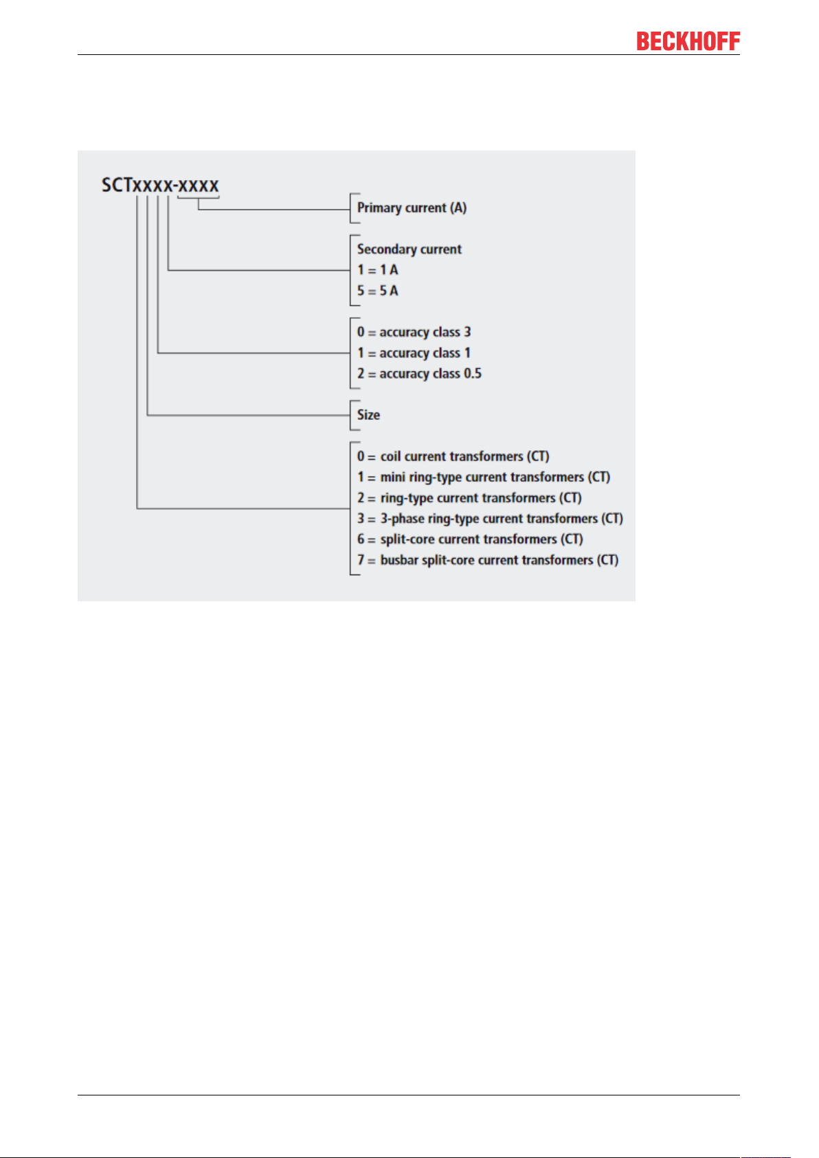
2.3 Product categories – SCTxxxx current transformer
Breakdown of the type designation of the SCT current transformer
Fig.4: Designation key of the SCT current transformers
SCT2xxx12 Version: 1.3
Page 13
Product overview
Coil current transformers
Fig.5: SCT0xxx
In order to guarantee the power transmission, current transformers need a correspondingly large measuring
core volume with decreasing primary rated currents. The dimensions of standard current transformers would
quickly hit their limits on the basis of this physical principle. The SCT0xxx coil current transformers with
electrical isolation are specially designed for these low primary rated currents and are used in corresponding
applications.
Coil current transformers
SCT0111 Accuracy class 1,
SCT0121 Accuracy class 0.5,
primary current 0…1 A AC to 0…30 A AC,
secondary current 1 A AC
primary current 0…1 A AC to 0…30 A AC,
secondary current 1 A AC
SCT2xxx 13Version: 1.3
Page 14
Product overview
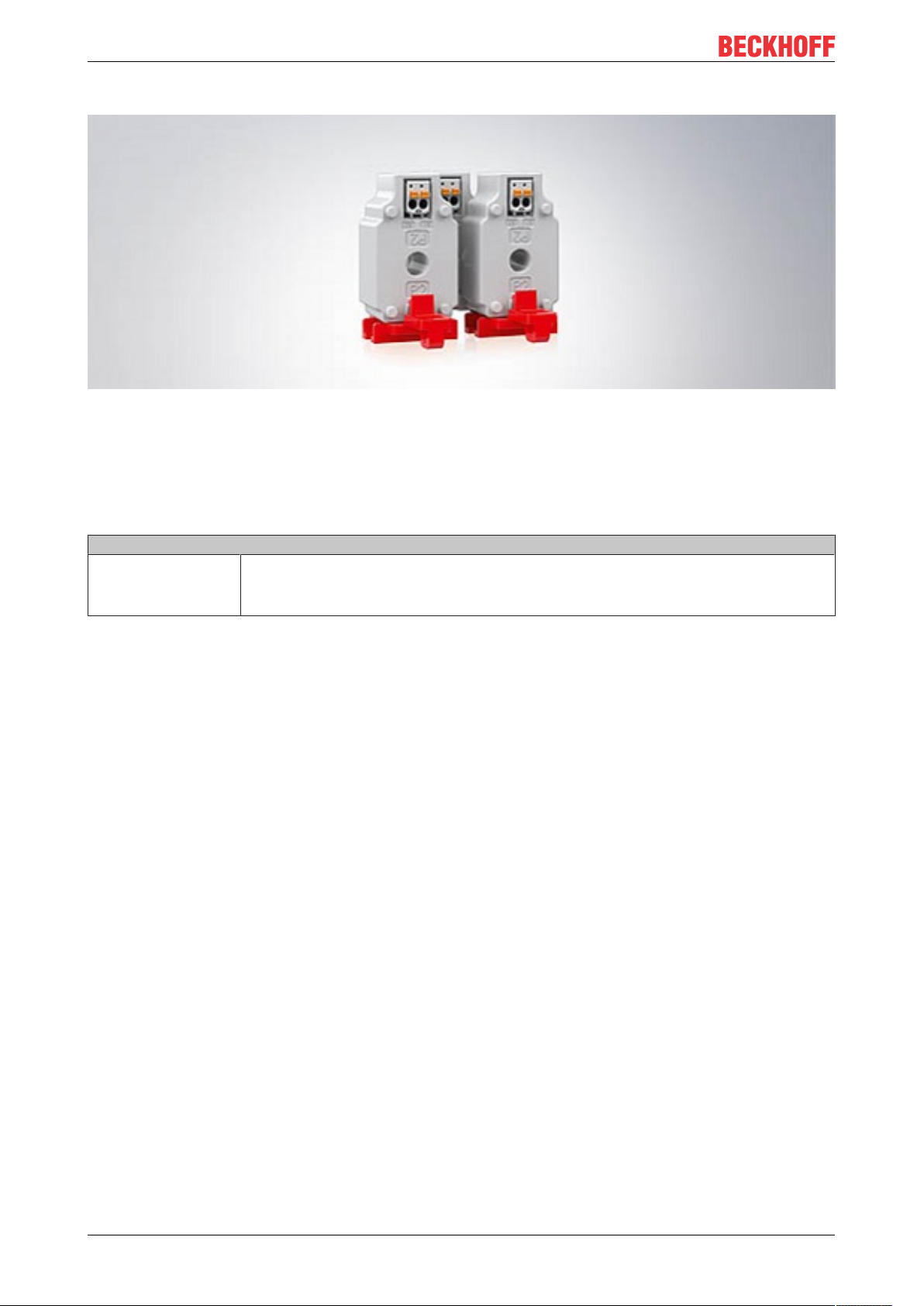
Mini ring-type current transformer
Fig.6: SCT1xxx
The SCT1111 mini ring-type current transformer can be positioned on a DIN rail by means of snap-on
fastening and is thus suitable for measurements in very tight installation spaces, e.g. directly in the subdistribution unit. Two current transformers are attached to the DIN rail, while the third current transformer in
plugged into the fastened current transformers.
The connection is realized via removable picoMAX® connectors, which enables pre-wiring.
Mini ring-type current transformer
SCT1111 Accuracy class 1,
primary current 0…32 A AC to 0…64 A AC,
secondary current 1 A AC,
max. diameter round conductor 7.6 mm (size 1)
SCT2xxx14 Version: 1.3
Page 15
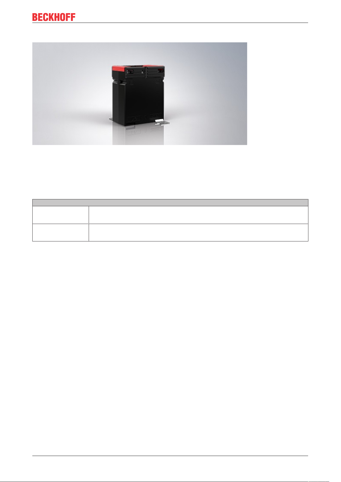
Ring-type current transformer
Fig.7: SCT2xxx
Product overview
The SCT2xxx series offers a large selection of ring-type current transformers for primary currents from 60 to
2500 A in six sizes and two accuracy classes. The innovative screwless connection technology for rigid and
flexible conductors saves time – ferrules can be dispensed with here.
SCT2xxx 15Version: 1.3
Page 16

Product overview
Ring-type current transformer
SCT2111 Accuracy class 1,
SCT2121 Accuracy class 0.5,
SCT2211 Accuracy class 1,
SCT2221 Accuracy class 0.5,
SCT2311 Accuracy class 1,
SCT2321 Accuracy class 0.5,
SCT2411 Accuracy class 1,
SCT2421 Accuracy class 0.5,
SCT2515 Accuracy class 1,
SCT2525 Accuracy class 0.5,
SCT2615 Accuracy class 1,
SCT2625 Accuracy class 0.5,
primary current 0…60 A AC to 0…500 A AC,
secondary current 1 A AC,
max. diameter round conductor 25.7 mm (size 1)
primary current 0…125 A AC to 0…600 A AC,
secondary current 1 A AC,
max. diameter round conductor 25.7 mm (size 1)
primary current 0…600 A AC / 0…750 A AC,
secondary current 1 A AC,
max. diameter round conductor 31.8 mm (size 2)
primary current 0…600 A AC / 0…750 A AC,
secondary current 1 A AC,
max. diameter round conductor 31.8 mm (size 2)
primary current 0…800 A AC / 0…1000 A AC,
secondary current 1 A AC,
max. diameter round conductor 43.7 mm (size 3)
primary current 0…800 A AC / 1000 A AC,
secondary current 1 A AC,
max. diameter round conductor 43.7 mm (size 3)
primary current 0…1250 A AC / 0…1500 A AC,
secondary current 1 A AC,
max. diameter round conductor 43.7 mm (size 4)
primary current 0…1250 A AC / 0…1500 A AC,
secondary current 1 A AC,
max. diameter round conductor 43.7 mm (size 4)
primary current 0…2000 A AC,
secondary current 5 A AC,
max. diameter round conductor 54.7 mm (size 5)
primary current 0…2000 A AC,
secondary current 5 A AC,
max. diameter round conductor 54.7 mm (size 5)
primary current 0…2500 A AC,
secondary current 5 A AC,
max. diameter round conductor 70 mm (size 6)
primary current 0…2500 A AC,
secondary current 5 A AC,
max. diameter round conductor 70 mm (size 6)
SCT2xxx16 Version: 1.3
Page 17
Product overview
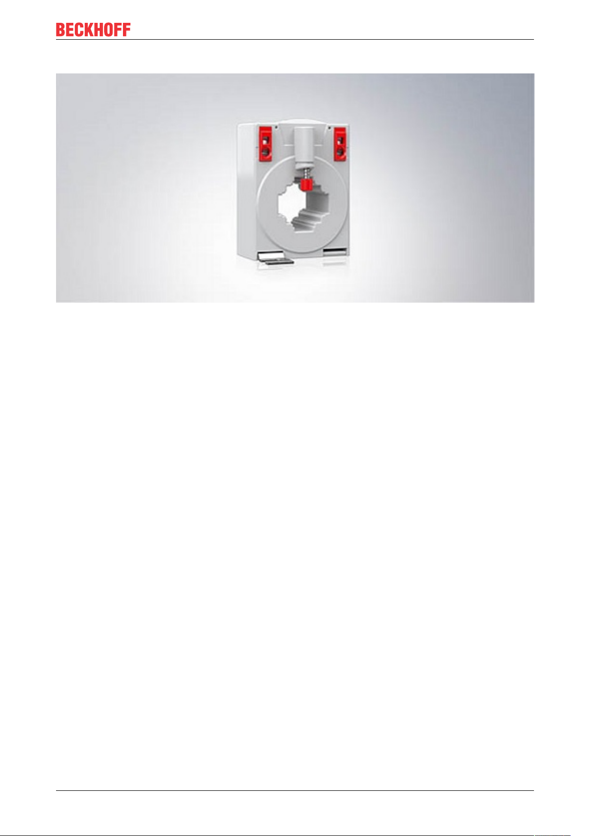
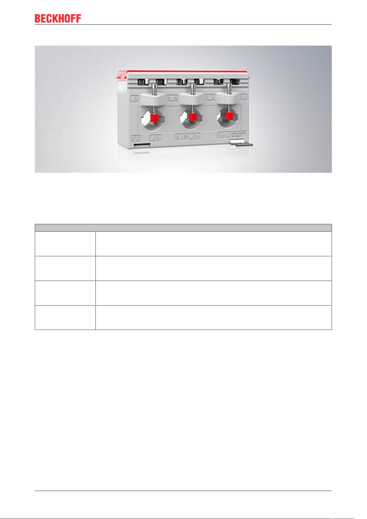
3-phase ring-type current transformers
Fig.8: SCT3xxx
The compact SCT3xxx 3-phase ring-type current transformers for direct mounting under commonly used
power switches measure primary currents from 3 x 50 to 3 x 600 A, with secondary currents of 1 or 5 A. The
whole of the SCT3xxx series is available in accuracy class 1 and is supplemented by the SCT3121-0125 and
SCT3121-0150 current transformers in accuracy class 0.5.
3-phase ring-type current transformers
SCT3111 Accuracy class 1,
SCT3121 Accuracy class 0.5,
SCT3215 Accuracy class 1,
SCT3315 Accuracy class 1,
primary current 3 x 0…50 A AC to 3 x 0…150 A AC,
secondary current 1 A AC,
max. diameter round conductor 13.5 mm (size 1)
primary current 3 x 0…125 A AC / 3 x 0…150 A AC,
secondary current 1 A AC,
max. diameter round conductor 13.5 mm (size 1)
primary current 3 x 0…100 A AC to 3 x 0…250 A AC,
secondary current 5 A AC,
max. diameter round conductor 18 mm (size 2)
primary current 3 x 0…250 A AC to 3 x 0…600 A AC,
secondary current 5 A AC,
max. diameter round conductor 22 mm (size 3)
SCT2xxx 17Version: 1.3
Page 18
Product overview
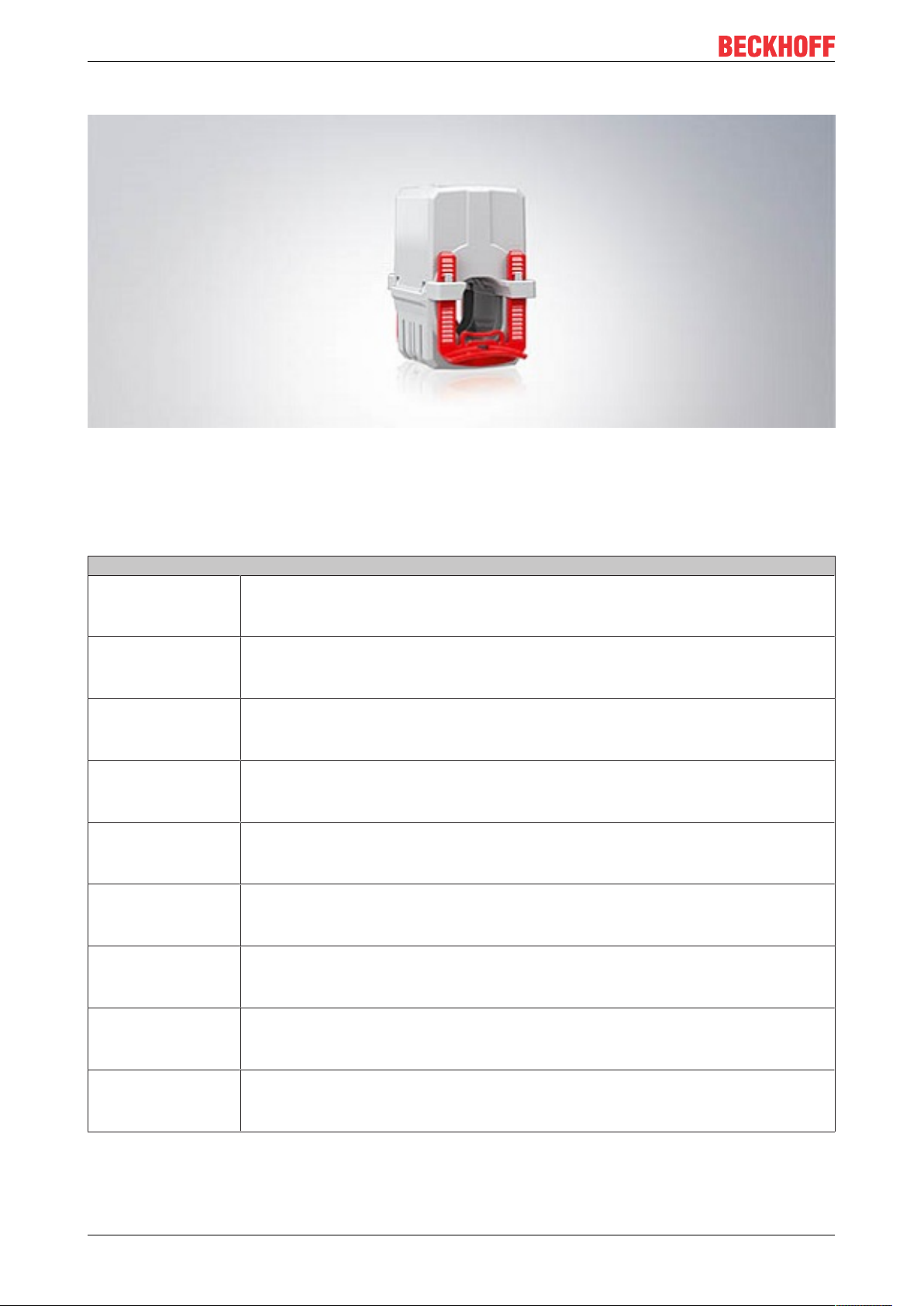
Split-core current transformers
Fig.9: SCT6xxx
The separable measuring system of the SCT6xxx split-core current transformers enables flexible retrofitting
without disconnecting the primary conductor. Due to the minimal installation effort, they are suitable for use
in places that are difficult to access or where space is limited. Four sizes are available. Accuracy class 3 is
suitable for primary currents from 60 to 150A, accuracy class 1 for 200 to 1000A.
Split-core current transformers
SCT6101 Accuracy class 3,
SCT6311 Accuracy class 1,
SCT6321 Accuracy class 0.5,
SCT6411 Accuracy class 1,
SCT6421 Accuracy class 0.5,
SCT6615 Accuracy class 1,
SCT6625 Accuracy class 0.5,
SCT6715 Accuracy class 1,
SCT6725 Accuracy class 0.5,
primary current 0…60 A AC to 0…150 A AC,
secondary current 1 A AC,
max. diameter round conductor 18.5 mm (size 1)
primary current 0…200 A AC / 0…250 A AC,
secondary current 1 A AC,
max. diameter round conductor 18.5 mm (size 3)
primary current 0…200 A AC / 0…250 A AC,
secondary current 1 A AC,
max. diameter round conductor 18.5 mm (size 3)
primary current 0…300 A AC to 0…500 A AC,
secondary current 1 A AC,
max. diameter round conductor 27.9 mm (size 4)
primary current 0…400 A AC / 0…500 A AC,
secondary current 1 A AC,
max. diameter round conductor 27.9 mm (size 4)
primary current 0…600 A AC / 0…750 A AC,
secondary current 5 A AC,
max. diameter round conductor 42.4 mm (size 6)
primary current 0…600 A AC / 0…750 A AC,
secondary current 5 A AC,
max. diameter round conductor 42.4 mm (size 6)
primary current 0…800 A AC / 0…1000 A AC,
secondary current 5 A AC,
max. diameter round conductor 2 x 42.4 mm (size 7)
primary current 0…800 A AC / 0…1000 A AC,
secondary current 5 A AC,
max. diameter round conductor 2 x 42.4 mm (size 7)
SCT2xxx18 Version: 1.3
Page 19

Product overview
Busbar split-core current transformers
Fig.10: SCT71xx
Like the SCT6xxx series, the SCT7xxx busbar split-core current transformers for primary currents up to
5000A can be retrofitted to existing systems with no great mounting effort. From 500A, there is a choice
between accuracy class 0.5 and 1 for each primary current. The SCT7105-0100 and SCT7105-200 current
transformers support accuracy class 3.
Busbar split-core current transformers
SCT7105 Accuracy class 3,
SCT7115 Accuracy class 1,
SCT7125 Accuracy class 0.5,
SCT7215 Accuracy class 1,
SCT7225 Accuracy class 0.5,
SCT7315 Accuracy class 1,
SCT7325 Accuracy class 0.5,
SCT7415 Accuracy class 1,
SCT7425 Accuracy class 0.5,
primary current 0…100 A AC / 0…200 A AC,
secondary current 5 A AC,
max. diameter round conductor 20 mm (size 1)
primary current 0…200 A AC / 450 A AC,
secondary current 5 A AC,
max. diameter round conductor 20 mm (size 1)
primary current 0…400 A AC,
secondary current 5 A AC,
max. diameter round conductor 20 mm (size 1)
primary current 0…500 A AC / 0…600 A AC,
secondary current 5 A AC,
max. diameter round conductor 50 mm (size 2)
primary current 0…500 A AC / 0…600 A AC,
secondary current 5 A AC,
max. diameter round conductor 50 mm (size 2)
primary current 0…750 A AC to 0…1500 A AC,
secondary current 5 A AC,
max. diameter round conductor 80 mm (size 3)
primary current 0…750 A AC to 0…1500 A AC,
secondary current 5 A AC,
max. diameter round conductor 80 mm (size 3)
primary current 0…1500 A AC to 0…5000 A AC,
secondary current 5 A AC,
max. diameter round conductor 80 mm (size 4)
primary current 0…1500 A AC to 0…5000 A AC,
secondary current 5 A AC,
max. diameter round conductor 80 mm (size 4)
SCT2xxx 19Version: 1.3
Page 20

Product overview
2.4 Notes on class accuracy SCT transformers
Current transformers are divided into classes according to their accuracy. The Beckhoff SCT current
transformers are available in the standard accuracy classes 0.5; 1 and 3, depending on the product
category. The class designation corresponds to an error curve with regard to current amplitude and angular
error. Beckhoff SCT current transformers conform to the IEC 61869 standard.
The accuracy classes of current transformers are related to the rated current. If current transformers are
operated with a current that is low in relation to the rated current, the measuring accuracy decreases. The
following tables show the fault limit values taking into account the rated current values:
Class accuracy Current error (±) in % at % of rated current
5 % 20 % 50 % 100 % 120 %
0,5 1,5 % 0,75 % - 0,5 % 0,5 %
1 3,0 % 1,5 % - 1,0 % 1,0 %
3 - - 3 % - 3 %
Class accuracy Phase shift/error angle (±) at % of rated current
Angular minutes [ ´ ] Radians [rad]
5 % 20 % 50 % 100 % 120 % 5 % 20 % 50 % 100 % 120 %
0,5 90‘ 45‘ - 30‘ 30‘ 2,7 rad 1,35 rad - 0,9 rad 0,9 rad
1 180‘ 90‘ - 60‘ 60‘ 5,4 rad 2,7 rad - 1,8 rad 1,8 rad
3 - - - - - - - - - -
Fig.11: Characteristic curves accuracy classes/primary current
Adjusting the transducer rating
In order to use the optimum accuracy of the transducer, you must ensure a suitable transducer rating in your application through the wiring between the transducer and the measuring terminal. This
is done by using 0.25 to 1.0 times the rated power of the transducer.
Additional resistors in the secondary path can be used to match the transducer and measuring terminal to each other.
SCT2xxx20 Version: 1.3
Page 21

Technical data
3 Technical data
3.1 SCT21xx | Ring-type current transformer, size 1
3.1.1 SCT21xx | General
Primary side SCT21xx-xxxx
Thermal rated continuous current I
Rated short-time thermal current I
Rated impulse current I
Rated frequency f
dyn
R
cth
th
Secondary side SCT21xx-xxxx
Secondary rated current I
sr
Overcurrent limiting factor FS5
≤2000A: 1,2 * I
>2000A: 1,0 * I
N
N
60 * IN /1 s (max. 100 kA)
2,5 * I
th
50..60 Hz
1 A
Operating conditions SCT21xx-xxxx
Permissible ambient temperature range during
-5…+50 °C
operation
Permissible ambient temperature range during
-25 … +70 °C
storage
Permissible relative humidi 5 … 85 %
Operating height Up to 1000 m
Protection class IP20
Insulation characteristics SCT21xx-xxxx
Rated insulation level U
m
Surge voltage resistance according to DIN EN 61439
1,2/6/- kV
12 kV (1,2/50 µs)
1:2012-06
Insulation class E
Gerneral data SCT21xx-xxxx
Max. Diameter conductor bushing primary conductor 25,7 mm
Rail dimensions primary conductor 30 mm x 10 mm / 25 mm x 12 mm / 20 mm x 20mm
Connection technology secondary CAGE CLAMP ®
Conductor cross section secondary 2,5 … 4 mm² / 14-12 AWG
Stripping length 9 – 10 mm / 0,37 in
Size 1
Dimensions (W x H x D) 60 mm x 81 mm x 52 mm
Weight 305 g
Standards and regulations SCT21xx-xxxx
Approvals/Markings CE, UL
Standards/Regulations IEC 61869-1; IEC 61869-2
SCT2xxx 21Version: 1.3
Page 22

Technical data
SCT21xx dimensions, size 1
Fig.12: Isometric view, top view; all dimensions in mm
Fig.13: Right side view, front view, left side view; all dimensions in mm
Conductor bushing of the primary conductor, size 1
Rail 1 [mm] 30 x 10
Rail 2 [mm] 25 x 12
Rail 3 [mm] 20 x 20
Round conductor [mm] Ø 25,7
SCT2xxx22 Version: 1.3
Page 23

3.1.2 SCT2111 | Ring-type current transformer for primary currents 0...60 A to 0...500 A, accuracy class 1, size 1
Technical data SCT2111-xxxx
Accuracy class 1
Primary current I
Secondary current I
N
sr
Versions
SCT2111-0060 ratio60/1,
rated power 1.25VA
SCT2111-0075 ratio75/1,
rated power 2.5VA
SCT2111-0080 ratio80/1,
rated power 2.5VA
SCT2111-0100 ratio100/1,
rated power 2.5VA
SCT2111-0125 ratio125/1,
rated power 2.5VA
SCT2111-0150 ratio150/1,
rated power 5VA
SCT2111-0200 ratio200/1,
rated power 5VA
SCT2111-0250 ratio250/1,
rated power 5VA
SCT2111-0300 ratio 300/1,
rated power 10VA
SCT2111-0400 ratio 400/1,
rated power 10VA
SCT2111-0500 ratio500/1,
rated power 10VA
0…60 A AC to 0…500 A AC
1 A AC
Technical data
SCT2xxx 23Version: 1.3
Page 24

Technical data
3.1.3 SCT2121 | Ring-type current transformer for primary currents 0…125 A to 0…600 A, accuracy class 0.5, size 1
Technical data SCT2121-xxxx
Accuracy class 0.5
Primary current I
Secondary current I
N
sr
Versions
SCT2121-0125 ratio125/1,
rated power 1.5VA
SCT2121-0150 ratio150/1,
rated power 2.5VA
SCT2121-0200 ratio200/1,
rated power 2.5VA
SCT2121-0250 ratio250/1,
rated power 5VA
SCT2121-0300 ratio300/1,
rated power 5VA
SCT2121-0400 ratio400/1,
rated power 10VA
SCT2121-0500 ratio500/1,
rated power 10VA
SCT2121-0600 ratio600/1,
rated power 10VA
0…125 A AC to 0…600A AC
1 A AC
SCT2xxx24 Version: 1.3
Page 25

Technical data
3.2 SCT22xx | Ring-type current transformer, size 2
3.2.1 SCT22xx | General
Primary side SCT22xx-xxxx
Thermal rated continuous current I
Rated short-time thermal current I
Rated impulse current I
Rated frequency f
dyn
R
cth
th
Secondary side SCT22xx-xxxx
Secondary rated current I
sr
Overcurrent limiting factor FS5
Operating conditions SCT22xx-xxxx
Permissible ambient temperature range during
operation
Permissible ambient temperature range during
storage
Permissible relative humidi 5 … 85 %
Operating height Up to 1000 m
Protection class IP20
≤2000A: 1,2 * I
>2000A: 1,0 * I
N
N
60 * IN /1 s (max. 100 kA)
2,5 * I
th
50..60 Hz
1 A
-5…+50 °C
-25 … +70 °C
Insulation characteristics SCT22xx-xxxx
Rated insulation level U
m
Surge voltage resistance according to DIN EN 61439
1,2/6/- kV
12 kV (1,2/50 µs)
1:2012-06
Insulation class E
Gerneral data SCT22xx-xxxx
Max. Diameter conductor bushing primary conductor 31,8 mm
Rail dimensions primary conductor 40 mm x 10 mm / 30 mm x 15 mm
Connection technology secondary CAGE CLAMP ®
Conductor cross section secondary 2,5 … 4 mm² / 14-12 AWG
Stripping length 9 – 10 mm / 0,37 in
Size 2
Dimensions (W x H x D) 70 mm x 91 mm x 52 mm
Weight 315 g
Standards and regulations SCT22xx-xxxx
Approvals/Markings CE, UL
Standards/Regulations IEC 61869-1; IEC 61869-2
SCT2xxx 25Version: 1.3
Page 26
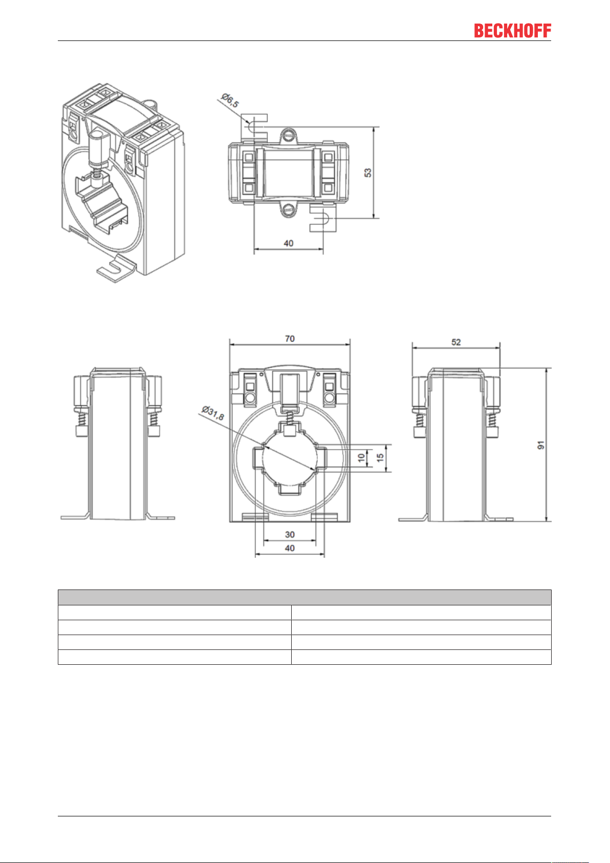
Technical data
SCT22xx dimensions, size 2
Fig.14: Isometric view, top view; all dimensions in mm
Fig.15: Right side view, front view, left side view; all dimensions in mm
Conductor bushing of the primary conductor, size 2
Rail 1 [mm] 40 x 10
Rail 2 [mm] 30 x 15
Rail 3 [mm] /
Round conductor [mm] Ø 31,8
SCT2xxx26 Version: 1.3
Page 27

3.2.2 SCT2211 | Ring-type current transformer for primary currents 0...600 A/0...750 A, accuracy class 1, size 2
Technical data SCT2211-xxxx
Accuracy class 1
Primary current I
Secondary current I
N
sr
Versions
SCT2211-0400 ratio400/1,
rated power 5VA
SCT2211-0600 ratio600/1,
rated power 10VA
SCT2211-0750 ratio750/1,
rated power 10VA
600 A AC / 750A AC
1 A AC
Technical data
SCT2xxx 27Version: 1.3
Page 28

Technical data
3.2.3 SCT2221 | Ring-type current transformer for primary currents 0…600 A/0…750 A, accuracy class 0.5, size 2
Technical data SCT2221-xxxx
Accuracy class 0.5
Primary current I
Secondary current I
N
sr
Versions
SCT2221-0400 ratio400/1,
rated power 5VA
SCT2221-0600 ratio600/1,
rated power 10VA
SCT2221-0750 ratio750/1,
rated power 10VA
600 A AC / 750A AC
1 A AC
SCT2xxx28 Version: 1.3
Page 29

Technical data
3.3 SCT23xx | Ring-type current transformer, size 3
3.3.1 SCT23xx | General
Primary side SCT23xx-xxxx
Thermal rated continuous current I
Rated short-time thermal current I
Rated impulse current I
Rated frequency f
dyn
R
cth
th
Secondary side SCT23xx-xxxx
Secondary rated current I
sr
Operating conditions SCT23xx-xxxx
Permissible ambient temperature range during
operation
Permissible ambient temperature range during
storage
Permissible relative humidi 5 … 85 %
Operating height Up to 1000 m
Protection class IP20
≤2000A: 1,2 * I
>2000A: 1,0 * I
N
N
60 * IN /1 s (max. 100 kA)
2,5 * I
th
50..60 Hz
1 A
-5…+50 °C
-25 … +70 °C
Insulation characteristics SCT23xx-xxxx
Rated insulation level U
m
Surge voltage resistance according to DIN EN 61439
1,2/6/- kV
12 kV (1,2/50 µs)
1:2012-06
Insulation class E
Gerneral data SCT23xx-xxxx
Max. Diameter conductor bushing primary conductor 43,7 mm
Rail dimensions primary conductor 50 mm x 12 mm / 40 mm x 30 mm
Connection technology secondary CAGE CLAMP ®
Conductor cross section secondary 2,5 … 4 mm² / 14-12 AWG
Stripping length 9 – 10 mm / 0,37 in
Size 3
Dimensions (W x H x D) 85 mm x 105 mm x 52 mm
Weight 340 g
Standards and regulations SCT23xx-xxxx
Approvals/Markings CE, UL
Standards/Regulations IEC 61869-1; IEC 61869-2
SCT2xxx 29Version: 1.3
Page 30
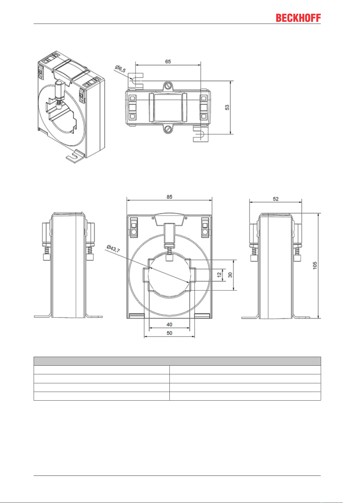
Technical data
SCT23xx dimensions, size 3
Fig.16: Isometric view, top view; all dimensions in mm
Fig.17: Right side view, front view, left side view; all dimensions in mm
Conductor bushing of the primary conductor, size 3
Rail 1 [mm] 50 x 12
Rail 2 [mm] 40 x 30
Rail 3 [mm] /
Round conductor [mm] Ø 43,7
SCT2xxx30 Version: 1.3
Page 31

3.3.2 SCT2311 | Ring-type current transformer for primary currents 0…800 A/0…1000 A, accuracy class 1, size 3
Technical data SCT2311-xxxx
Accuracy class 1
Primary current I
Secondary current I
N
sr
Versions
SCT2311-0800 ratio800/1,
rated power 10VA
SCT2311-1000 ratio1000/1,
rated power 10VA
800 A AC / 1000A AC
1 A AC
Technical data
SCT2xxx 31Version: 1.3
Page 32

Technical data
3.3.3 SCT2321 | Ring-type current transformer for primary currents 0…800 A/0…1000 A, accuracy class 0.5, size 3
Technical data SCT2321-xxxx
Accuracy class 0.5
Primary current I
Secondary current I
N
sr
Versions
SCT2321-0800 ratio800/1,
rated power 10VA
SCT2321-1000 ratio1000/1,
rated power 10VA
800 A AC / 1000A AC
1 A AC
SCT2xxx32 Version: 1.3
Page 33

Technical data
3.4 SCT24xx | Ring-type current transformer, size 4
3.4.1 SCT24xx | General
Primary side SCT24xx-xxxx
Thermal rated continuous current I
Rated short-time thermal current I
Rated impulse current I
Rated frequency f
dyn
R
cth
th
Secondary side SCT24xx-xxxx
Secondary rated current I
sr
Overcurrent limiting factor FS5
Operating conditions SCT24xx-xxxx
Permissible ambient temperature range during
operation
Permissible ambient temperature range during
storage
Permissible relative humidi 5 … 85 %
Operating height Up to 1000 m
Protection class IP20
≤2000A: 1,2 * I
>2000A: 1,0 * I
N
N
60 * IN /1 s (max. 100 kA)
2,5 * I
th
50..60 Hz
1 A
-5…+50 °C
-25 … +70 °C
Insulation characteristics SCT24xx-xxxx
Rated insulation level U
m
Surge voltage resistance according to DIN EN 61439
1,2/6/- kV
12 kV (1,2/50 µs)
1:2012-06
Insulation class E
Gerneral data SCT24xx-xxxx
Max. Diameter conductor bushing primary conductor 43,7 mm
Rail dimensions primary conductor 63 mm x 10 mm / 50 mm x 30 mm
Connection technology secondary CAGE CLAMP ®
Conductor cross section secondary 2,5 … 4 mm² / 14-12 AWG
Stripping length 9 – 10 mm / 0,37 in
Size 4
Dimensions (W x H x D) 95 mm x 115 mm x 52 mm
Weight 470 g
Standards and regulations SCT24xx-xxxx
Approvals/Markings CE, UL
Standards/Regulations IEC 61869-1; IEC 61869-2
SCT2xxx 33Version: 1.3
Page 34

Technical data
SCT24xx dimensions, size 4
Fig.18: Isometric view, top view; all dimensions in mm
Fig.19: Right side view, front view, left side view; all dimensions in mm
Conductor bushing of the primary conductor, size 4
Rail 1 [mm] 63 x 10
Rail 2 [mm] 50 x 30
Rail 3 [mm] /
Round conductor [mm] Ø 43,7
SCT2xxx34 Version: 1.3
Page 35

3.4.2 SCT2411 | Ring-type current transformer for primary currents 0…1250 A/0…1500 A, accuracy class 1, size 4
Technical data SCT2411-xxxx
Accuracy class 1
Primary current I
Secondary current I
N
sr
Versions
SCT2411-1250 ratio1250/1,
rated power 10VA
SCT2411-1500 ratio1500/1,
rated power 10VA
0…1250 A AC / 0…1500A AC
1 A AC
Technical data
SCT2xxx 35Version: 1.3
Page 36

Technical data
3.4.3 SCT2421 | Ring-type current transformer for primary currents 0…1250 A/0…1500 A, accuracy class 0.5, size 4
Technical data SCT2421-xxxx
Accuracy class 0.5
Primary current I
Secondary current I
N
sr
Versions
SCT2421-1250 ratio1250/1,
rated power 10VA
SCT2421-1500 ratio1500/1,
rated power 10VA
0…1250 A AC / 0…1500A AC
1 A AC
SCT2xxx36 Version: 1.3
Page 37

Technical data
3.5 SCT25xx | Ring-type current transformer, size 5
3.5.1 SCT25xx | General
Primary side SCT25xx-xxxx
Thermal rated continuous current I
Rated short-time thermal current I
Rated impulse current I
Rated frequency f
dyn
R
cth
th
Secondary side SCT25xx-xxxx
Secondary rated current I
sr
Overcurrent limiting factor FS5
Operating conditions SCT25xx-xxxx
Permissible ambient temperature range during
operation
Permissible ambient temperature range during
storage
Permissible relative humidi 5 … 85 %
Operating height Up to 1000 m
Protection class IP20
≤2000A: 1,2 * I
>2000A: 1,0 * I
N
N
60 * IN /1 s (max. 100 kA)
2,5 * I
th
50..60 Hz
5 A
-5…+50 °C
-25 … +70 °C
Insulation characteristics SCT25xx-xxxx
Rated insulation level U
m
Surge voltage resistance according to DIN EN 61439
1,2/6/- kV
12 kV (1,2/50 µs)
1:2012-06
Insulation class E
Gerneral data SCT25xx-xxxx
Max. Diameter conductor bushing primary conductor 54,7 mm
Rail dimensions primary conductor 80 mm x 10 mm / 60 mm x 30 mm
Connection technology secondary CAGE CLAMP ®
Conductor cross section secondary 2,5 … 4 mm² / 14-12 AWG
Stripping length 9 – 10 mm / 0,37 in
Size 5
Dimensions (W x H x D) 120 mm x 135 mm x 52 mm
Weight 660 g
Standards and regulations SCT25xx-xxxx
Approvals/Markings CE, UL
Standards/Regulations IEC 61869-1; IEC 61869-2
SCT2xxx 37Version: 1.3
Page 38

Technical data
SCT25xx dimensions, size 5
Fig.20: Isometric view, top view; all dimensions in mm
Fig.21: Right side view, front view, left side view; all dimensions in mm
Conductor bushing of the primary conductor, size 5
Rail 1 [mm] 80 x 10
Rail 2 [mm] 60 x 30
Rail 3 [mm] /
Round conductor [mm] Ø 54,7
SCT2xxx38 Version: 1.3
Page 39

Technical data
3.5.2 SCT2515 | Ring-type current transformers for primary current 0…2000 A, accuracy class 1, size 5
Technical data SCT2515-xxxx
Accuracy class 1
Primary current I
Secondary current I
N
sr
Versions
SCT2515-2000 ratio2000/5,
rated power 15VA
0…2000A AC
5 A AC
SCT2xxx 39Version: 1.3
Page 40

Technical data
3.5.3 SCT2525 | Ring-type current transformers for primary current 0…2000 A, accuracy class 0.5, size 5
Technical data SCT2525-xxxx
Accuracy class 0.5
Primary current I
Secondary current I
N
sr
Versions
SCT2525-2000 ratio2000/5,
rated power 15VA
0…2000A AC
5 A AC
SCT2xxx40 Version: 1.3
Page 41

Technical data
3.6 SCT26xx | Ring-type current transformer, size 6
3.6.1 SCT26xx | General
Primary side SCT26xx-xxxx
Thermal rated continuous current I
Rated short-time thermal current I
Rated impulse current I
Rated frequency f
dyn
R
cth
th
Secondary side SCT26xx-xxxx
Secondary rated current I
sr
Overcurrent limiting factor FS5
Operating conditions SCT26xx-xxxx
Permissible ambient temperature range during
operation
Permissible ambient temperature range during
storage
Permissible relative humidi 5 … 85 %
Operating height Up to 1000 m
Protection class IP20
≤2000A: 1,2 * I
>2000A: 1,0 * I
N
N
60 * IN /1 s (max. 100 kA)
2,5 * I
th
50..60 Hz
5 A
-5…+50 °C
-25 … +70 °C
Insulation characteristics SCT26xx-xxxx
Rated insulation level U
m
Surge voltage resistance according to DIN EN 61439
1,2/6/- kV
12 kV (1,2/50 µs)
1:2012-06
Insulation class E
Gerneral data SCT26xx-xxxx
Max. Diameter conductor bushing primary conductor 70 mm
Rail dimensions primary conductor 100 mm x 10 mm / 80 mm x 30 mm
Connection technology secondary CAGE CLAMP ®
Conductor cross section secondary 2,5 … 4 mm² / 14-12 AWG
Stripping length 9 – 10 mm / 0,37 in
Size 6
Dimensions (W x H x D) 130 mm x 147 mm x 52 mm
Weight 710 g
Standards and regulations SCT26xx-xxxx
Approvals/Markings CE, UL
Standards/Regulations IEC 61869-1; IEC 61869-2
SCT2xxx 41Version: 1.3
Page 42
Technical data
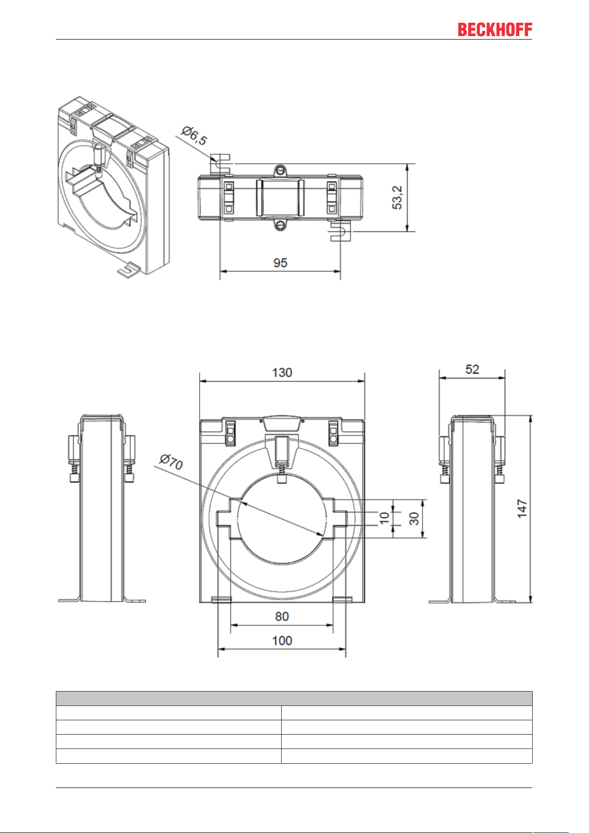
SCT26xx dimensions, size 6
Fig.22: Isometric view, top view; all dimensions in mm
Fig.23: Right side view, front view, left side view; all dimensions in mm
Conductor bushing of the primary conductor, size 6
Rail 1 [mm] 100 x 10
Rail 2 [mm] 80 x 30
Rail 3 [mm] /
Round conductor [mm] Ø 70
SCT2xxx42 Version: 1.3
Page 43

Technical data
3.6.2 SCT2615 | Ring-type current transformers for primary current 0…2500 A, accuracy class 1, size 6
Technical data SCT2615-xxxx
Accuracy class 1
Primary current I
Secondary current I
N
sr
Versions
SCT2615-2500 ratio2500/5A,
rated power 15VA
0…2500A AC
5 A AC
SCT2xxx 43Version: 1.3
Page 44

Technical data
3.6.3 SCT2625 | Ring-type current transformers for primary current 0...2500 A, accuracy class 0.5, size 6
Technical data SCT2625-xxxx
Accuracy class 0.5
Primary current I
Secondary current I
N
sr
Versions
SCT2625-2500 ratio2500/5,
rated power 15VA
0…2500A AC
5 A AC
SCT2xxx44 Version: 1.3
Page 45

Commissioning
4 Commissioning
DANGER
Open transformer circuits lead to electric shock and arc flashover!
Disregarding this will result in death, physical injury or considerable damage to property!
• Never open the secondary circuit of the current transformer under load.
• Short-circuit the secondary current terminals of the current transformer before removing the device.
WARNING
Hazardous voltage can lead to electric shock and burns!
• Make sure that the details on the name plate and in the "Technical data" correspond to the operating parameters of the system.
• Switch the system off before commencing with the installation!
WARNING
Induction of high voltages into the secondary circuit!
• If the secondary circuit of the current transformer is not under load (open), high voltages are induced on
its secondary terminals. The voltage values occurring there represent a danger to persons and the functional safety of the current transformer.
• "Open operation", i.e. operation of the current transformer without secondary wiring, must be avoided at
all costs.
• Make sure that the working environment is safe during assembly, maintenance and installation work.
Interrupt the power supply of the primary conductor and secure against being switched on again
inadvertently.
• Install the current transformer on the primary conductor.
• To do this, feed the primary conductor (copper bar or round conductor) through the window aperture of
the current transformer housing. The window aperture is marked with "K-P1" or "L-P2" respectively.
• The device can be fastened directly to the primary conductor or alternatively to a mounting plate. Use
the fastening materials included in the scope of delivery for this.
• Direct fastening to the primary conductor is done by screwing the fastening screws included in the
accessories pack into the screw bosses on the transformer housing or with the optionally available
quick-fix cable fastening (ZB8203-0210/ZB8203-0211 [}49]).
• Mounting on a mounting plate takes place with the base brackets also included in the accessories
pack.
• Current transformers of the types SCT21xx and SCT22xx can also be fastened to 35 mm DIN rails by
means of a snap-on mounting (ZB8201-0210 [}49]), which is available as an accessory.
• Make the secondary connections. Observe the markings "k-S1" and "l-S2" of the secondary terminals.
SCT2xxx 45Version: 1.3
Page 46

Commissioning
Measuring circuit
Fig.24: Measuring circuit - SCT0xxx/SCT1xxx/SCT2xxx transformer
SCT2xxx46 Version: 1.3
Page 47

Assembly notes
Fig.25: Actuation of the secondary connecting terminals (CAGE CLAMP®)
Commissioning
Fig.26: Mounting the fastening screws
Fig.27: Mounting on copper bar or round conductor
Fig.28: Mounting with quick-fix cable fastening (ZB8203-0210, ZB8203-0211)
SCT2xxx 47Version: 1.3
Page 48
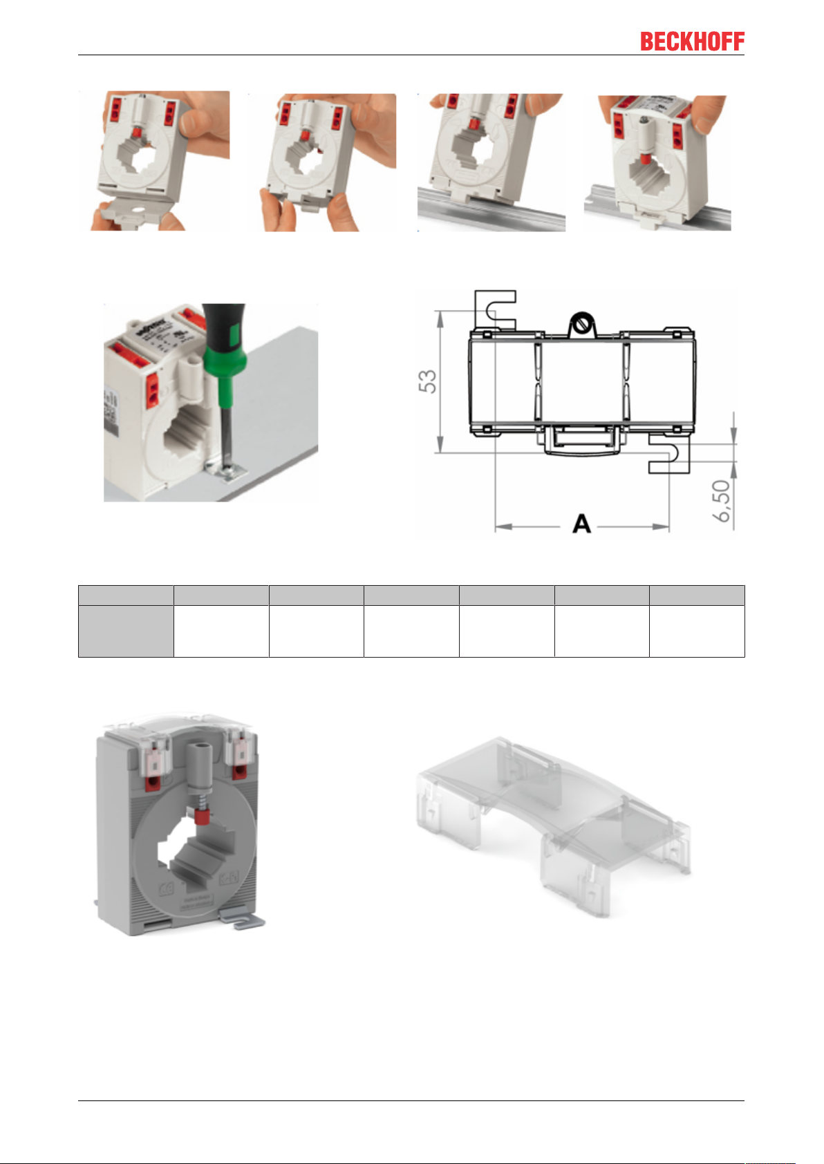
Commissioning
Fig.29: Mounting on 35 mm DIN rail with snap-on mounting (ZB8201-0210)
Fig.30: Mounting on mounting plate
SCT21xx SCT22xx SCT23xx SCT24xx SCT25xx SCT26xx
Dimension
"A"
[mm]
40 40 65 65 95 95
Fig.31: Mounted sealing plate
SCT2xxx48 Version: 1.3
Page 49

Fig.32: Snap-on mounting for 35 mm DIN rail, ZB8201-0210
Commissioning
Fig.33: Quick-fix cable fastening, ZB8203-0210 or ZB8203-0211 (extra heat-resistant)
Fig.34: Sealing plate, ZB8202-0210
SCT2xxx 49Version: 1.3
Page 50

Application example
5 Application example
5.1 Power measurement at a machine
WARNING
WARNING: Risk of electric shock!
Bring the Bus Terminal system into a safe, voltage-free state before starting mounting, disassembly or
wiring of the Bus Terminals!
NOTE
Attention! Risk of device damage!
Avoid confusing the current and voltage circuit during connection, since the direct connection of mains voltage to the terminal points for the current transformers (typical input resistance 100mΩ) would destroy the
power measurement terminal!
EL3443
• The voltage is measured via connections L1, L2, L3 and N.
• The current is measured via three current transformers (e.g. from the Beckhoff SCT series) and the
connections IL1, IL2, IL3 and IN (star point of the current transformers).
Fig.35: EL3443, power measurement at a machine
**) PE as star point for 3-phase systems without neutral line
Depending on the current transformers used, PE must be connected as star point in 3-phase systems without neutral line as shown in Fig. “EL3443, power measurement at a machine ".
Observe the regulations of the manufacturer of the current transformers!
Negative power values
If negative power values are measured on a circuit, please check whether the associated current
transformer circuit is connected correctly.
EL3453
• The voltage is measured via connections L1, L2, L3 and N.
SCT2xxx50 Version: 1.3
Page 51

Application example
• The current is measured via 4 current transformers (e.g. from the Beckhoff SCT series) and the
connections IL1, IL2, IL3 and IN (star point of the current transformers).
Fig.36: EL3453, power measurement at a machine
Negative power values
If negative power values are measured on a circuit, please check whether the associated current
transformer circuit is connected correctly.
SCT2xxx 51Version: 1.3
Page 52

Appendix
6 Appendix
6.1 Documentation issue status
Version Comment
1.3 - Addenda chapter ”Notes on class accuracy SCT transformers”
1.2 - SCT2211-0400 and SCT2221-0400 added
1.1 - Addenda & corrections
1.0 - 1st public issue
- Addenda & corrections
SCT2xxx52 Version: 1.3
Page 53

6.2 UL notes
"Conditions of Acceptability" for SCT2xxx
Conditions of Acceptability
• These devices shall be used within the Recognized ratings as indicated.
• Each transformer shall be mounted within equipment that will provide a metal or noncombustible material enclosure for the transformer.
• The acceptability of the secondary terminals shall be determined in the final application.
• This transformer has not been tested for accuracy, impulse and mechanical tests per
ANSI C57.13 or CSA CAN3-13-M83. Only temperature and voltage withstand tests at 60
Hz were performed.
• These transformers are designated as ’55 deg rise transformers’, for use in an ambient
shown in the rating table.
Appendix
SCT2xxx 53Version: 1.3
Page 54

Appendix
6.3 Support and Service
Beckhoff and their partners around the world offer comprehensive support and service, making available fast
and competent assistance with all questions related to Beckhoff products and system solutions.
Beckhoff's branch offices and representatives
Please contact your Beckhoff branch office or representative for local support and service on Beckhoff
products!
The addresses of Beckhoff's branch offices and representatives round the world can be found on her internet
pages: https://www.beckhoff.com
You will also find further documentation for Beckhoff components there.
Beckhoff Support
Support offers you comprehensive technical assistance, helping you not only with the application of
individual Beckhoff products, but also with other, wide-ranging services:
• support
• design, programming and commissioning of complex automation systems
• and extensive training program for Beckhoff system components
Hotline: +49 5246 963 157
Fax: +49 5246 963 9157
e-mail: support@beckhoff.com
Beckhoff Service
The Beckhoff Service Center supports you in all matters of after-sales service:
• on-site service
• repair service
• spare parts service
• hotline service
Hotline: +49 5246 963 460
Fax: +49 5246 963 479
e-mail: service@beckhoff.com
Beckhoff Headquarters
Beckhoff Automation GmbH & Co. KG
Huelshorstweg 20
33415 Verl
Germany
Phone: +49 5246 963 0
Fax: +49 5246 963 198
e-mail: info@beckhoff.com
web:
https://www.beckhoff.com
SCT2xxx54 Version: 1.3
Page 55

Page 56

More Information:
www.beckhoff.com/SCT2xxx
Beckhoff Automation GmbH & Co. KG
Hülshorstweg 20
33415 Verl
Germany
Phone: +49 5246 9630
info@beckhoff.com
www.beckhoff.com
 Loading...