

Page 1

PT100 4-fold temperature measurement Beckhoff II/O System
PT100 4-fold temperature measurement
Technical description
Eiserstraße 5 Telephone: 05246/709-0
D-33415 Verl Fax: 05246/70980
Date : 12 March 97 Version : 1.1 Page 1 of 10
Page 2

PT100 4-fold temperature measurement Beckhoff II/O System
Table of contents
1. Hardware functional description ..................................................3
2. Software functional description.....................................................5
3. Technical specifications..................................................................7
4. Installation instructions..................................................................8
5. Terminal diagram.........................................................................10
Page 2 of 10 Version : 1.1 Date : 12 March 97
Page 3
PT100 4-fold temperature measurement Beckhoff II/O System
1. Hardware functional description
PT100
General information
The PT100 module is a temperature measurement module for use in an II/O system. Up to
four sensors (PT100) may be connected to each module.
A diagnostic LED is furnished for the II/O optical fibre guide ring:
LD1 The red ’ERROR’ LED is switched on after detection of an error message (check
sum, frame) and switched off after running three successive correct messages
(check sum, frame) have been run.
A match LED is furnished for initial matching:
LD2 The second (green) LED is used for control purposes when matching newly
connected sensors.
Date : 12 March 97 Version : 1.1 Page 3 of 10
Page 4

PT100 4-fold temperature measurement Beckhoff II/O System
Opt.Fibre
Opt.Fibre
Periphery controller
Processor
Converter
Block diagram
Page 4 of 10 Version : 1.1 Date : 12 March 97
Page 5

PT100 4-fold temperature measurement Beckhoff II/O System
2. Software functional description
Timing diagram:
Explanation of the timing diagram:
Signal assignment to II/O message data bytes:
Reset: D2.7
Select1 (priority 1): D2.0
Select2 (priority 2): D2.1
Select4 (priority 3): D2.2
Valid: D2.3
Data: D0.0 to D0.7
D1.0 to D1.7
The restart signal is used to reset the processor to the PT100 module. The signal remains at
"1" for continuous operation.
Date : 12 March 97 Version : 1.1 Page 5 of 10
Page 6

PT100 4-fold temperature measurement Beckhoff II/O System
Channels are pre-selected in accordance with Select 1-4 priorities.
Select1 Select2 Select4 Significance D0, D1
0 0 0 Measurement channel 1 is
selected.
1 0 0 Measurement channel 2 is
selected.
0 1 0 Measurement channel 3 is
selected.
1 1 0 Measurement channel 4 is
selected.
0 0 1 Control channel a is selected.
1 0 1 Control channel b is selected.
Pre-selection is valid with the falling edge (1=>0) of signal "Valid" D2.3.
Control channels a and b provide a specific bit pattern at selection. This allows for monitoring
of whether or not the microprocessor is active and properly operating.
Set value for control channel a: AA55 hex
Set value for control channel b: 55AA hex
The processor may be restarted by means of the D2.7 reset key if this alternating bit pattern is
not provided.
Page 6 of 10 Version : 1.1 Date : 12 March 97
Page 7

PT100 4-fold temperature measurement Beckhoff II/O System
3. Technical specifications
Number of channels
Resolution
Measurement value display
Converter range temperature
Monitoring
Connections
Data port
Transmission rate
Supply voltage
Four, (multiplex)
12 bit
2 byte, (ϑ x 10)
-50 to +150 degrees C
0 to +512 degrees C in progress
Display of two control channels for
monitoring the module,
reset via fibre-optic bus
Plug-in for PT100 sensor
(2-wire, 4-wire)
II/O system fibre-optic light guide
2.5 Mbaud, 25 µs for 32 bit
24 VDC (± 10%)
Power consumption
Casing type
Dimensions (W * H * D)
Weight
Operating temperature
Storage temperature
0.1 A
Open card carrier, snap-on device mounting
rail as specified in DIN EN 50022, 50035
168 * 111 * 65 mm
Approximately 550 g
±0..+55 øC
-20..+70 øC
Date : 12 March 97 Version : 1.1 Page 7 of 10
Page 8

PT100 4-fold temperature measurement Beckhoff II/O System
4. Installation instructions
Assembly
The PT100 module is connected to the II/O fibre-optical guide ring by means of fibre-optics
cable plug-in connectors (Toshiba). The maximum fibre-optical cable length to the adjacent
boxes should not exceed 45 m if plastic fibre-optical light guides are used and 600 m in the
case of glass-fibre. These values are only valid if bending radii of at least 30 mm are complied
with when running the fibre-optical cable. No special tools are required for attaching the
connectors if plastic fibre-optical light guides are used.
The Pt100 sensors are directly connected to the inputs (connecto r X 20) using two- or fourconductor cable (cf. wiring diagram).
Assembly of the PT100 module is performed by means of distributed configuration on the
unit or in the switchgear cabinet by simply snapping it onto a device mounting rail as
specified in DIN EN 50022 or DIN EN 50035.
Configuration
The D0 and D1 data bytes are entered into the configuration list as inputs and the D2 and D3
are entered as outputs.
The D0 and D1 data bytes of the II/O message contain the data of the four measurement
values (multiplexed).
Data byte D2 is used for selection and acceptance of the data of a m easurement channel. In
addition, the D2.7 key may be used to reset the microprocessor.
Data byte D3 is presently unassigned (spare slot).
Supply voltage
A tripolar connection terminal with ports for the control logic / analog portion is provided for
connecting 24V supply voltage (+) and ground (-) (connector X10). Connector X10 pin 3 is
unassigned.
Page 8 of 10 Version : 1.1 Date : 12 March 97
Page 9

Date : 12 March 97 Version : 1.1 Page 9 of 10
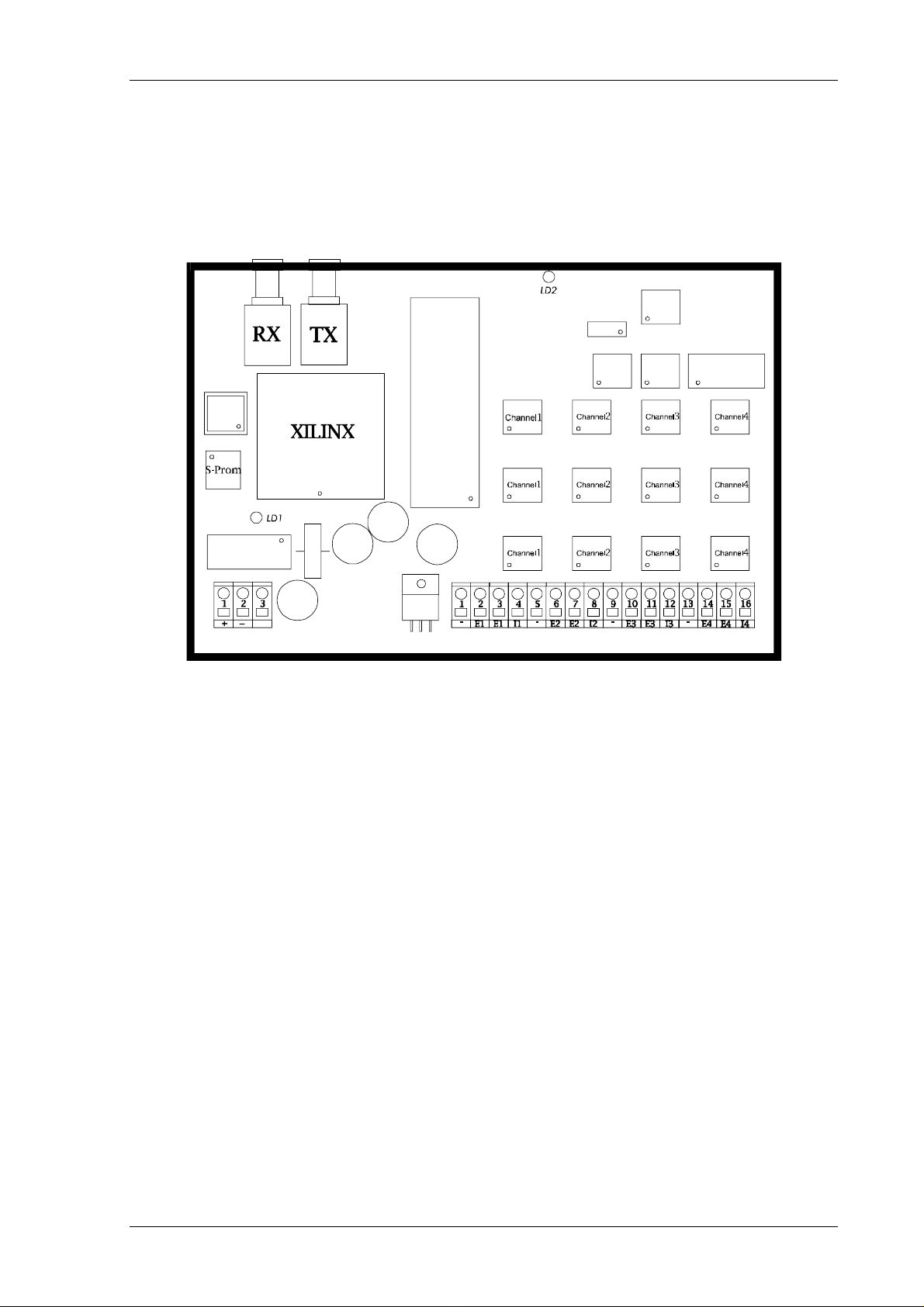
PT100 4-fold temperature measurement Beckhoff II/O System
PT100 4-fold temperature measurement
Optical-fibre transmitter
Optical-fibre receiver
Diagnose-LED
/' /('(UURU
S-Prom
/'
Channel
Channel
Channel
1
1
1
/'
LED alignment
/'
Channel
2
Channel
2
Channel
2
Channel
Channel
Channel
3
Channel
4
Channel
Channel
4
4
3
3
Plug-in connector
+24V
control logic/analog portion
Ground
Unassigned
Plug-in connector
GND for PT100 sensor
Input, PT100 sensor pick-off
Input, PT100 sensor pick-off
Constant-current source for PT100 sensor
Page 10

PT100 4-fold temperature measurement Beckhoff II/O System
5. Terminal diagram
Plug connection assignment and signal description
CONNECTOR X10
Plug Pin Signal
X10 1 +
X10 2 -
X10 3
Description
+24V supply voltage, control logic/analog
portion
Ground
Unassigned
CONNECTOR X10
Plug Pin Signal Description
X20 1 X20 2 E1
X20 3 E1
X20 4 I1
X20 5 X20 6 E2
X20 7 E2
X20 8 I2
X20 9 X20 10 E3
X20 11 E3
X20 12 I3
X20 13 X20 14 E4
X20 15 E4
X20 16 I4
GND for PT100 sensor
Input, PT100 se nsor pick-off
Input, PT100 se nsor pick-off
Constant-current source for PT100 sens or
(1mA)
GND for PT100 sensor
Input, PT100 se nsor pick-off
Input, PT100 se nsor pick-off
Constant-current source for PT100 sens or
(1mA)
GND for PT100 sensor
Input, PT100 se nsor pick-off
Input, PT100 se nsor pick-off
Constant-current source for PT100 sens or
(1mA)
GND for PT100 sensor
Input, PT100 se nsor pick-off
Input, PT100 se nsor pick-off
Constant-current source for PT100 sens or
(1mA)
Important: A bridge has to be inserted at the input for all of the unused channels. Open
inputs are capable of affecting the values of the other channels.
Example: If a PT100 sensor is not connected to channels 2 and 4, then pin 6 has to be
bridged with pin 7 and pin 14 with pin 15.
Page 10 of 10 Version : 1.1 Date : 12 March 97
 Loading...