

Page 1
Documentation | EN
PS2031-2410-0000
Power supply 24 V DC, 10 A, 3-phase
2020-10-08 | Version: 1.0
Page 2

Page 3

Table of contents
Table of contents
1 Overview.....................................................................................................................................................5
2 Foreword ....................................................................................................................................................6
2.1 Notes on the documentation..............................................................................................................6
2.2 Safety instructions .............................................................................................................................7
2.3 Terminology and abbreviations .......................................................................................................10
3 Technical data, mounting, wiring...........................................................................................................11
3.1 AC input...........................................................................................................................................11
3.2 DC input...........................................................................................................................................13
3.3 Input inrush current..........................................................................................................................14
3.4 Output..............................................................................................................................................15
3.5 Hold-up time ....................................................................................................................................16
3.6 Efficiency and losses .......................................................................................................................17
3.7 Lifetime expectancy.........................................................................................................................18
3.8 MTBF...............................................................................................................................................19
3.9 Terminals and wiring .......................................................................................................................20
3.10 Functional wiring diagram................................................................................................................21
3.11 Front side and operating elements ..................................................................................................22
3.12 EMC.................................................................................................................................................23
3.13 Environment ....................................................................................................................................24
3.14 Protective functions .........................................................................................................................25
3.15 Safety features ................................................................................................................................25
3.16 Dielectric strength............................................................................................................................26
3.17 Declaration of conformity and approvals .........................................................................................27
3.18 Dimensions and weight ...................................................................................................................28
4 Application notes.....................................................................................................................................29
4.1 Peak current capability ....................................................................................................................29
4.2 Output circuit breakers ....................................................................................................................30
4.3 Charging batteries ...........................................................................................................................31
4.4 Series connection ............................................................................................................................31
4.5 Parallel use to increase power ........................................................................................................31
4.6 Operation on two phases.................................................................................................................32
4.7 Use in a tightly sealed enclosure.....................................................................................................33
4.8 Installation positions ........................................................................................................................34
5 Appendix ..................................................................................................................................................36
5.1 Accessories .....................................................................................................................................36
5.2 Documentation issue status ............................................................................................................38
5.3 Support and Service ........................................................................................................................39
PS2031-2410-0000 3Version: 1.0
Page 4

Table of contents
PS2031-2410-00004 Version: 1.0
Page 5
1 Overview
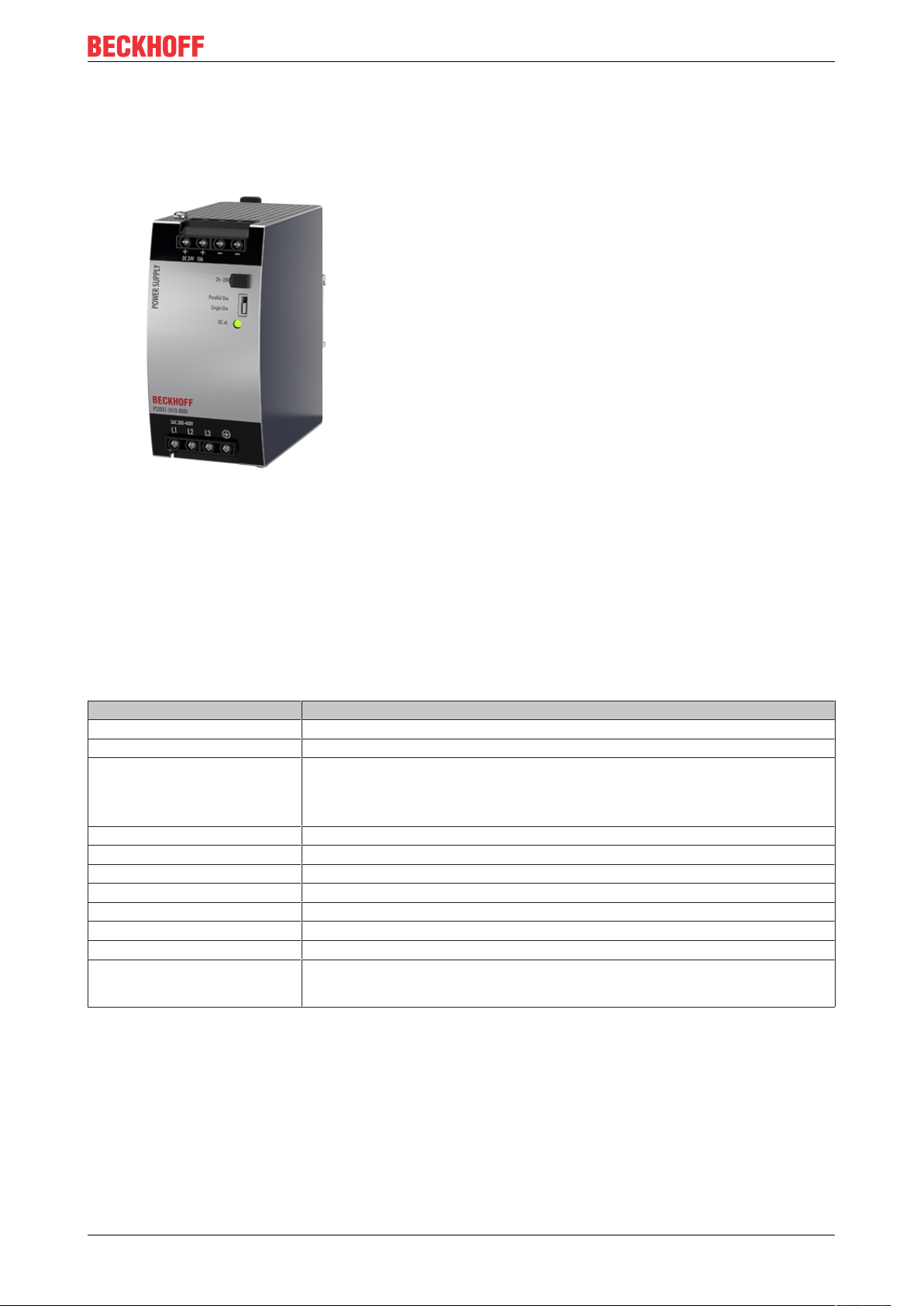
PS2031-2410-0000 | Power supply 24V, 10A, 3-phase, Extra Power
• 3AC 380-480V wide-range input
• 2- or 3-phase operation possible
• Width only 62mm
• Efficiency up to 92.9% thanks to synchronous rectifier
• Excellent part-load efficiency
• 120% peak power, 288W
• Precise triggering of fuses through high overload / peak current
• Integrated input transient suppression circuit
• Minimum inrush current surge
• 3 integrated input fuses
• Current-sharing function for parallel use
• Full output between -25°C and +60°C
Overview
The PS2031-2410-0000 is a 3-phase 24V power supply unit with an output current of 10A and an output
power of 240W.
On the input side, the device features a wide-range input, harmonic correction (PFC) and inrush current
limitation.
The PS2031-2410-0000 features an Extra Power output with a continuous maximum output power of 120%
and is able to trigger fuses precisely with a short-term peak current.
The power supply unit is part of the PS2000 family and has a width of 62 mm. A DC OK LED monitors the
status of the output voltage
Overview of technical data
Overview of technical data PS2031-2410-0000
Output voltage DC 24V (nominal factory setting 24.1V)
Adjustment range 24 - 28V
Output current 12.0-10.3A (amb. below +45°C)
Input voltage AC 3AC 380-480V -15%/+20%
Mains frequency 50-60Hz ±6%
Input current AC 0.7 / 0.6A at 3x400 / 480Vac
Efficiency 92.8 / 92.9% at 3x400 / 480Vac
Temperature range -25°C to +70°C
Size (W x H x D) 62 x 124 x 117mm (without DIN rail)
Weight 750g
Approvals/markings CE
*)
10.0-8.6A (amb. at +60°C)
7.5-6.5A (amb. at +70°C)
Linear load reduction between +45°C and +70°C
cULus
EAC
*) All values typical for 24V, 10A, 3x 400Vac, 50Hz, symmetrical mains voltages, 25°C ambient temperature and after a warm-up
time of five minutes, unless otherwise stated
PS2031-2410-0000 5Version: 1.0
Page 6

Foreword
2 Foreword
2.1 Notes on the documentation
Copyright
© Beckhoff Automation GmbH & Co. KG, Germany.
The reproduction, distribution and utilization of this document as well as the communication of its contents to
others without express authorization are prohibited.
Offenders will be held liable for the payment of damages. All rights reserved in the event of the grant of a
patent, utility model or design.
Disclaimer
The documentation has been prepared with care. The products described are, however, constantly under
development.
We reserve the right to revise and change the documentation at any time and without prior announcement.
No claims for the modification of products that have already been supplied may be made on the basis of the
data, diagrams and descriptions in this documentation.
Trademarks
Beckhoff®, TwinCAT®, EtherCAT®, EtherCATG®, EtherCATG10®, EtherCATP®, SafetyoverEtherCAT®,
TwinSAFE®, XFC®, XTS® and XPlanar® are registered trademarks of and licensed by Beckhoff Automation
GmbH. Other designations used in this publication may be trademarks whose use by third parties for their
own purposes could violate the rights of the owners.
Patent Pending
The EtherCAT Technology is covered, including but not limited to the following patent applications and
patents: EP1590927, EP1789857, EP1456722, EP2137893, DE102015105702 with corresponding
applications or registrations in various other countries.
Intended audience
This description is only intended for the use of trained specialists in control and automation engineering who
are familiar with the applicable national standards.
It is essential that the documentation and the following notes and explanations are followed when installing
and commissioning these components.
It is the duty of the technical personnel to use the documentation published at the respective time of each
installation and commissioning.
The responsible staff must ensure that the application or use of the products described satisfy all the
requirements for safety, including all the relevant laws, regulations, guidelines and standards.
PS2031-2410-00006 Version: 1.0
Page 7

2.2 Safety instructions
Description of instructions
In this documentation the following instructions are used.
These instructions must be read carefully and followed without fail!
DANGER
Serious risk of injury!
Failure to follow this safety instruction directly endangers the life and health of persons.
WARNING
Risk of injury!
Failure to follow this safety instruction endangers the life and health of persons.
CAUTION
Personal injuries!
Failure to follow this safety instruction can lead to injuries to persons.
Foreword
NOTE
Damage to environment/equipment or data loss
Failure to follow this instruction can lead to environmental damage, equipment damage or data loss.
Tip or pointer
This symbol indicates information that contributes to better understanding.
Intended use
This device is designed for installation in a housing and is intended for general professional use, for example
in industrial control systems or office, communication and measuring equipment.
Do not use this power supply in installations where a malfunction could cause serious injury or danger to
human life.
Exclusion of liability
All the components are supplied in particular hardware and software configurations appropriate for the
application. Modifications to hardware or software configurations other than those described in the
documentation are not permitted, and nullify the liability of Beckhoff Automation GmbH & Co. KG.
Personnel qualification
This description is only intended for trained specialists in control, automation and drive engineering who are
familiar with the applicable national standards.
Safety regulations
Please note the following safety instructions and explanations!
Product-specific safety instructions can be found on following pages or in the areas mounting, wiring,
commissioning etc.
PS2031-2410-0000 7Version: 1.0
Page 8

Foreword
Safety instructions and installation requirements for PS2031-2410-0000 power supply unit
DANGER
Danger of electric shock, fire, injuries, injuries resulting in death!
• Do not use the power supply without proper earthing (protective conductor). Use the terminal at the input
terminal strip for the earth connection, not one of the screws on the housing.
• Switch off the power supply before working on the device. Provide protection against unintentional reconnection.
• Ensure proper wiring by following all local and national regulations.
• Do not modify or attempt to repair the device.
• Do not open the device, as high voltages are present inside.
• Avoid foreign bodies entering the housing.
• Do not use the device in damp locations or in areas where moisture or condensation is likely to occur.
• Do not touch the device when it is switched on or immediately after it has been switched off. Hot surfaces can cause burns.
PS2031-2410-00008 Version: 1.0
Page 9

Foreword
Further notes on installation requirements
• This device contains no serviceable parts. In the event of damage or malfunction during installation or operation, switch off the device immediately and return it to the factory for inspection. Triggering of an internal fuse indicates an internal defect.
• Install the device in a housing that provides protection against electrical, mechanical and fire
hazards.
• Install the device on a DIN rail according to EN 60715, with the input terminals at the bottom of
the device. Other mounting positions require a reduction of the output current.
• Make sure that the wiring is correct. Make sure that all individual wires of a strand enter the terminal connection.
• Unused screw terminals should be tightened firmly.
• The device is designed for areas with contamination level 2 in controlled environments. No condensation or frost is allowed.
• The device housing offers IP20 protection.
• The device insulation is designed to withstand surge voltages of overvoltage category III according to IEC 60664-1. For delta protective conductor systems, the overvoltage category is reduced
to level II.
• The device is designed to meet the requirements of protection class I according to IEC 61140.
• Do not use the device without a proper PE connection (protective earth).
• The device is suitable for supply from TN, TT and IT networks. The voltage between the L or N
terminal and the PE terminal must not exceed 500Vac continuously.
• An isolating device must be provided for the device input.
• This device is designed for convection cooling and does not require an external fan. Do not obstruct the air circulation.
• The device is designed for altitudes up to 6000m (19685ft). Above 2000m (6560ft) a reduction of
the output current and overvoltage category is required.
• Maintain the following installation distances: 40mm at the top, 20mm at the bottom and 5mm
on the left and right are recommended if the device continuously runs at more than 50% of the
rated output. Increase this distance to 15mm if the adjacent device is a heat source (e.g. another power supply unit). If the device continuously runs at less than 50%, the 5mm distance
can be reduced to zero.
• The device is designed, tested and approved for branch-circuit currents up to 32A (IEC) and
30A (UL) without additional protection. If an external fuse is used, do not use circuit breakers
smaller than 6A (B or C characteristic) to avoid unwanted tripping of the circuit breaker.
• The maximum ambient air temperature is +70°C (+158°F). The operating temperature corresponds to the ambient or ambient air temperature, per definition at 2 cm below the device.
• The device is designed for operation in the relative humidity range between 5% and 95%.
PS2031-2410-0000 9Version: 1.0
Page 10

Foreword
2.3 Terminology and abbreviations
PE and the earthing
symbol
Earth, ground The terms earth and ground are synonymous and are used interchangeably in this
T.b.d. Still to be defined, value or description will follow in due course.
AC 400V A value preceded by "AC" or "DC" represents a nominal voltage or a nominal
400Vac A value followed by the unit Vac or Vdc is an instantaneous value that does not
50Hz vs. 60Hz Unless otherwise specified, AC 230V parameters are valid at a mains frequency of
may A keyword indicating a choice without implied preference.
shall A keyword indicating a mandatory requirement.
should A keyword indicating a choice with a clearly preferred method of implementation.
PE is the abbreviation for "protective earth" and has the same meaning as the
earthing symbol
document.
voltage range. The nominal voltage or the nominal voltage range may be provided
with tolerances. (e.g., AC380 - 480V ±15%). The calculated total range then
indicates the working range of the device.
Example:
DC 12V refers to a 12V battery, regardless of whether it is fully charged
(13.7Vdc) or discharged (10Vdc).
contain any additional tolerances.
50Hz.
PS2031-2410-000010 Version: 1.0
Page 11
Technical data, mounting, wiring
3 Technical data, mounting, wiring
3.1 AC input
The device is suitable for being supplied with AC voltage from TN, TT and IT networks. Earthing of one
phase is permitted, except for UL508 applications.
The device can also be operated at only two phases of a three-phase system. For further information see
chapter Two-phase operation [}32].
AC input
AC input Nom. 3AC 380-480V Suitable for TN, TT and IT networks
AC input range Min. 3x 323-576Vac Continuous operation
Min. 3x 576-700Vac For up to 1000ms max.
Permissible voltage L or N to earth Max. 500Vac Continuous according to IEC 62477-1
Input frequency Nom. 50–60Hz ±6%
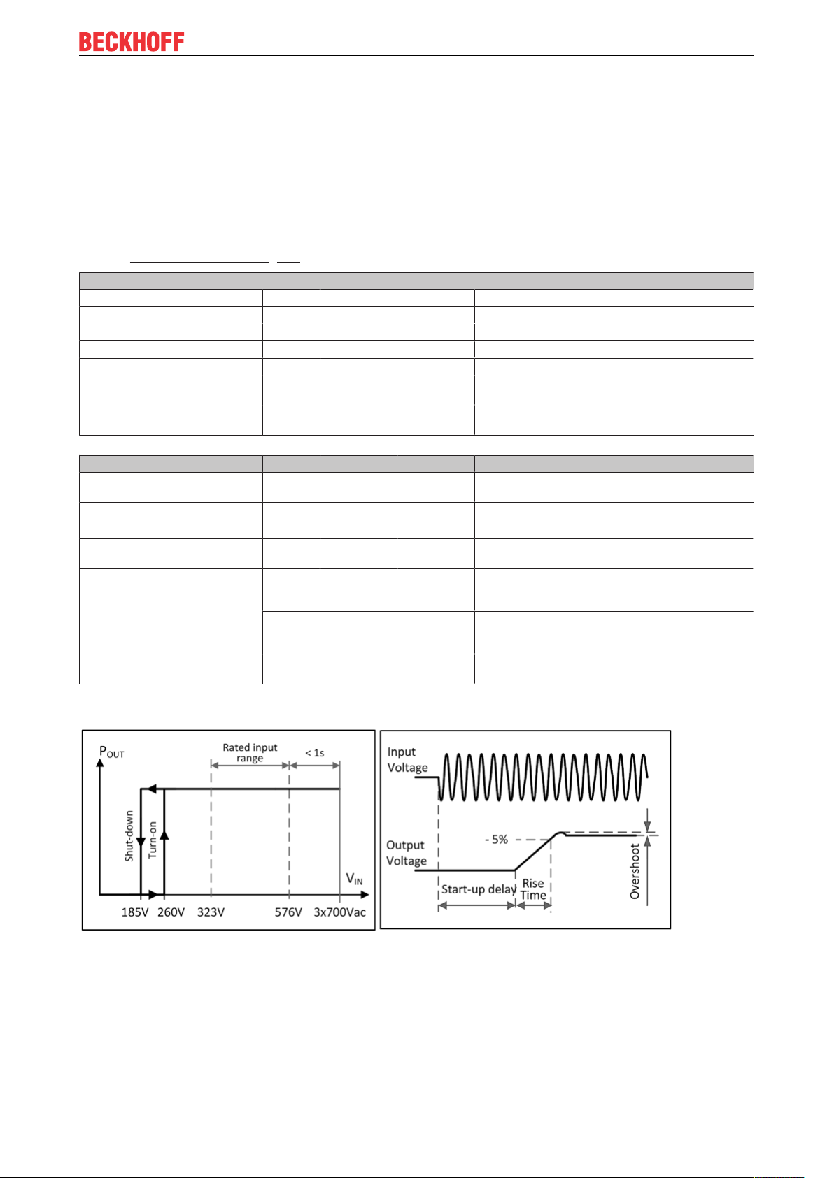
Turn-on voltage Typ. 3x 260Vac Static, see Fig. Input voltage range; switch-on behavior
Shut-down voltage Typ. 3x 185Vac Static, see Fig. Input voltage range; switch-on behavior
definitions
definitions
AC input 3AC 400V 3AC 480V
Input current Typ. 0.7A 0.6A At 24V, 10A per phase, see Fig. Input current over
Power factor*) Typ. 0.53 0.52 At 24V, 10A, see Fig. Input current over output cur-
Start-up delay Typ. 90ms 90ms See Fig. Input voltage range; switch-on behavior defini-
Rise time Typ. 40ms 40ms At 24V, 10A constant current load, 0mF load capac-
Typ. 85ms 85ms At 24V, 10A constant current load, 10mF load capac-
Turn-on overshoot Max. 200mV 200mV See Fig. Input voltage range; switch-on behavior defini-
output current; power factor over output current
rent; power factor over output current
tions
ity, see Fig. Input voltage range; switch-on behavior
definitions
ity, see Fig. Input voltage range; switch-on behavior
definitions
tions
*) The power factor is the ratio of real (or active) power to apparent power in an AC circuit.
Fig.1: Input voltage range; switch-on behavior definitions
PS2031-2410-0000 11Version: 1.0
Page 12

Technical data, mounting, wiring
Fig.2: Input current over output current; power factor over output current
PS2031-2410-000012 Version: 1.0
Page 13

3.2 DC input
Do not use the power supply unit with DC input voltages!
Technical data, mounting, wiring
PS2031-2410-0000 13Version: 1.0
Page 14

Technical data, mounting, wiring
3.3 Input inrush current
Active inrush current limitation limits the inrush current surge after the input voltage is switched on.
The charge current of the interference suppression capacitors during the first few microseconds after
switching on is not taken into account.
3AC 400V 3AC 480V
Input inrush
current
Inrush energy Max. 0.5A²s 0.5A²s
Max. 10A
Typ. 4A
peak
peak
10A
4A
peak
peak
temperature-independent
Fig.3: Typical switch-on behavior at nominal load, 25°C ambient temperature
PS2031-2410-000014 Version: 1.0
Page 15

Technical data, mounting, wiring
3.4 Output
The output provides an SELV/PELV nominal voltage that is electrically isolated from the input voltage.
The device is designed to supply any type of load, including capacitive and inductive loads.
The output is electronically protected against overload, no-load and short circuit. In the event of a protection
event, audible noises may occur
Output voltage Nom. 24V
Adjustment range Min. 24-28V Guaranteed value
Max. 30.0V This is the maximum output voltage that can occur in the end position of the po-
Factory settings Typ. 24.1V ±0.2%, single use at full load (cold device)
Line regulation Max. 10mV Between 3x 323 and 3x 576Vac
Load regulation Max. 100mV Between 0 and 10A, static value, single use
Typ. 1000mV Between 0 and 10A, static value, parallel use, see Fig. Output voltage over
Residual ripple and ripple
voltage
Output current Nom. 12A
Safety
switch-off current
Overload behavior Continuous cur-
Short circuit current Max. 23A Continuous current, see Fig. Output voltage over output current, typ.
Output capacity Typ. 6500μF Included in the power supply
Load feedback Max. 35V The device is resistant to load feedback and will not indicate a malfunction if a
Max. 50mV
Nom. 10A At 24V and 60°C ambient temperature
Nom. 7.5A At 24V and 70°C ambient temperature
Nom. 10.3A
Nom. 8.6A At 28V and 60°C ambient temperature
Nom. 6.5A At 28V and 70°C ambient temperature
Linear derating between +45°C and +70°C
Typ. 23A Up to 20ms once every five seconds, see Fig. Output voltage over output cur-
SS
1)
1)
rent
tentiometer in clockwise direction due to tolerances. It is not a guaranteed
value that can be achieved.
±0.2%, parallel use at 10A (cold device)
(23.9V ±0.2% at 12A and 25.0V ±0.2% at zero load)
output current (parallel use) typ.
Bandwidth 20Hz to 20MHz, 50Ohm
At 24V and ambient temperature below 45°C
At 28V and ambient temperature below 45°C
rent, typ.
The fuse output current is an increased transient current that contributes to the
tripping of fuses on faulty output branches. The output voltage remains above
20V.
see Fig. Output voltage over output current, typ.
load is feeding voltage back into the power supply. It does not matter whether
the power supply is switched on or off. The absorbed energy can be determined by means of the built-in large-size output capacitor.
1)
This current is also available for temperatures up to +70°C with a duty cycle of 10% and/or no more than 1
minute every 10 minutes.
Fig.4: Output voltage over output current (single use); output voltage over output current (parallel use).
PS2031-2410-0000 15Version: 1.0
Page 16

Technical data, mounting, wiring
3.5 Hold-up time
3AC 400V 3AC 480V
Power failure
Hold-up time
Typ. 34ms 54ms At 24V, 10A, see Fig. Hold-up time over
Typ. 68ms 108ms At 24V, 5A, see Fig. Hold-up time over input
Min. 28ms 44ms At 24V, 10A, see Fig. Hold-up time over
Min. 56ms 87ms At 24V, 5A, see Fig. Hold-up time over input
input voltage
voltage
input voltage
voltage
Fig.5: Hold-up time over input voltage; switch-off behavior, definitions
PS2031-2410-000016 Version: 1.0
Page 17

Technical data, mounting, wiring
3.6 Efficiency and losses
3AC 400V 3AC 480V
Efficiency Typ. 92.8% 92.9% At 24V, 10A, 3-phase operation
Typ. 92.4% 92.6% At 24V, 10A, 2 phase operation in a 3-phase system,
see chapter Two-phase operation [}32]
Average efficiency*)Typ. 92.2% 92.0% 25% at 2.5A, 25% at 5A,
25% at 7.5A, 25% at 10A, 3-phase operation
Losses Typ. 2.3W 2.6W At 24V, 0A, 3-phase operation
Typ. 11.8W 11.8W At 24V, 5A, 3-phase operation
Typ. 18.6W 18.3W At 24V, 10A, 3-phase operation
Typ. 23.5W 22.8W At 24V, 12A, 3-phase operation
*)
The average efficiency is based on assumptions for a typical application with the power supply unit
operating at 25% of the nominal load during 25% of the time, 50% of the nominal load during 25% of the
time, 75% of the nominal load during 25% of the time and 100% of the nominal load during the remaining
time.
Fig.6: Efficiency over output current; losses over output current
Fig.7: Efficiency over input voltage; losses over input voltage
PS2031-2410-0000 17Version: 1.0
Page 18

Technical data, mounting, wiring
3.7 Lifetime expectancy
The lifetime expectancy shown in the table indicates the minimum number of operating hours (service life)
and is determined by the lifetime expectancy of the built-in electrolytic capacitors. The lifetime expectancy is
stated in operating hours and is calculated according to the specifications of the capacitor manufacturer. The
manufacturer of the electrolytic capacitors only guarantees a maximum life of up to 15 years (131,400h). Any
number exceeding this value represents a calculated theoretical lifetime which can be used to compare
devices.
3AC 400V 3AC 480V
Lifetime
expectancy
Lifetime
expectancy
54,000h 62,000h At 24V, 10A and +40°C, 3-phase operation
133,000h 134,000h At 24V, 5A and +40°C, 3-phase operation
41,000h 47,000h At 24V, 12A and +40°C, 3-phase operation
151,000h 176,000h At 24V, 10A and +25°C, 3-phase operation
376,000h 379,000h At 24V, 5A and +25°C, 3-phase operation
116,000h 133,000h At 24V, 12A and +25°C, 3-phase operation
48,000h 58,000h At 24V, 10A and +40°C, 2-phase operation
134,000h 145,000h At 24V, 5A and +40°C, 2-phase operation
36,000h 42,000h At 24V, 12A and +40°C, 2-phase operation
135,000h 164,000h At 24V, 10A and +25°C, 2-phase operation
379,000h 410,000h At 24V, 5A and +25°C, 2-phase operation
102,000h 119,000h At 24V, 12A and +25°C, 2-phase operation
PS2031-2410-000018 Version: 1.0
Page 19

Technical data, mounting, wiring
3.8 MTBF
MTBF stands for Mean Time Between Failure, which is calculated from the statistical failure rate of the
components and indicates the reliability of a device. It is a statistical representation of the probability of
equipment failure and does not necessarily represent the service life of a product.
The MTBF number is a statistical representation of the probability of equipment failure. An MTBF number of
1,000,000h, for example, means that statistically, if there are 10,000 devices in use, one device will fail every
100 hours. However, it is not possible to say whether the failed device has been in operation for 50,000
hours or only 100 hours.
For these device types the MTTF value (Mean Time To Failure) is identical to the MTBF value.
3AC 400V 3AC 480V
MTBF SN 29500,
IEC 61709
MTBF MIL HDBK
217F
975,000h 985,000h At 24V, 10A and 40°C, 3-phase operation
1,706,000h 1,723,000h At 24V, 10A and 25°C, 3-phase operation
925,000h 939,000h At 24V, 10A and 40°C, 2-phase operation
1,633,000h 1,656,000h At 24V, 10A and 25°C, 2-phase operation
444,000h 428,000h At 24V, 10A and 40°C, 3-phase operation, Ground Benign
GB40
584,000h 563,000h At 24V, 10A and 25°C, 3-phase operation, Ground Benign
GB25
100,000h 100,000h At 24V, 10A and 40°C, 3-phase operation, Ground Fixed GF40
132,000h 132,000h At 24V, 10A and 25°C, 3-phase operation, Ground Fixed GF25
436,000h 423,000h At 24V, 10A and 40°C, 2-phase operation, Ground Benign
GB40
555,000h 572,000h At 24V, 10A and 25°C, 2-phase operation, Ground Benign
GB25
98,000h 98,000h At 24V, 10A and 40°C, 2-phase operation, Ground Fixed GF40
129,000h 129,000h At 24V, 10A and 25°C, 2-phase operation, Ground Fixed GF25
PS2031-2410-0000 19Version: 1.0
Page 20

Technical data, mounting, wiring
3.9 Terminals and wiring
The terminals are designed to be finger-safe according to IP20 and are suitable for field or factory wiring.
Technical data Input Output
Connection cross-section e*: max. 6mm²
f*: max. 4mm²
a*: max. 4mm² (d<2.8mm)
Connection cross section
(AWG)
Strip length 7mm / 0.28inch 7mm / 0.28inch
e* = solid single wire
f* = stranded wire
a* = with ferrule
Wiring instructions:
• Use suitable copper cables that are designed for at least the following operating temperatures: +60°C
for ambient temperatures up to +45°C, +75°C for ambient temperatures up to +60°C, and +90°C for
ambient temperatures up to +70°C.
• Observe the national installation rules and regulations!
• Make sure that all single wires of a strand are connected to the terminal!
• Unused terminals should be tightened firmly.
• Ferrules are permitted.
e*: AWG 20-10
f*: AWG 20-10
a* AWG 20-10 (d<2.8mm)
e*: max. 6mm²
f*: max. 4mm²
a*: max 4mm² (d<2.8mm)
e*: AWG 20-10
f*: AWG 20-10
a* AWG 20-10 (d<2.8mm)
Series connection of power supply units:
Series connection (looping from one power supply output to the next) is permitted as long as the average
output current flowing through a connection pin does not exceed 25A. For higher currents please use a
separate distributor terminal strip as shown in Fig. Using distribution terminals.
Fig.8: Series connection of outputs; use of distribution terminals
PS2031-2410-000020 Version: 1.0
Page 21

3.10 Functional wiring diagram
Fig.9: Functional wiring diagram
Technical data, mounting, wiring
PS2031-2410-0000 21Version: 1.0
Page 22

Technical data, mounting, wiring
3.11 Front side and operating elements
Fig.10: Front PS2031-2410-0000
Input terminals (screw terminals)
Designation (A) Description
L1, L2, L3 Mains input L1, L2, L3
PE input (protective conductor)
Output terminals (screw terminals)
Designation (B) Description
+ two identical positive poles, positive output
- two identical negative poles, negative output
Potentiometer for the output voltage
Designation (C) Description
Potentiometer cover Open the flap to adjust the output voltage. Factory setting: 24.1V
"Parallel Use" or "Single Use" mode
Designation (D) Description
Jumper for "Single Use"
or "Parallel Use"
Set the jumper to "Parallel Use" if devices are connected in parallel to increase the output power.
In order to distribute the load current among the individual power supply units, the "Parallel Use" mode
regulates the output voltage so that the voltage at zero load is approx. 4% higher than at nominal load.
A missing jumper corresponds to "Single Use" mode, which is the factory setting.
DC OK LED
Designation (E) Description
Push-in terminals
13 / 14
Monitors the output voltage of the active power supply.
See chapter on DC OK relay contact for more information.
PS2031-2410-000022 Version: 1.0
Page 23

Technical data, mounting, wiring
3.12 EMC
The EMC behavior of the device is designed for applications in industrial environments as well as residential,
commercial or small business environments. The output may be earthed or non-earthed.
The device was tested according to EN 61000-6-1, EN 61000-6-2, EN 61000-6-3 and EN 61000-6-4.
Without additional measures to reduce emissions at the output (e.g. by using a filter), the device is not
suitable for supplying a local DC power network in residential, commercial or small business environments.
There are no restrictions for local DC power networks in industrial environments.
EMC interference immunity
Strong transients VDE 0160 Over the entire load
EMC interference emission
Cable-related interference emission, input
lines
Interference emission EN 55011, EN 55022 Class B
Harmonic input current EN 61000-3-2 Class A requirements met
Voltage fluctuations, flicker EN 61000-3-3 Requirements met
This device complies with FCC Part 15.
Operation is subject to the following two conditions: (1) This device may not cause harmful interference, and (2) this device must be
able to deal with any interference received, including interference that may cause undesired operation.
EN 55011, EN 55022, FCC Part 15,
CISPR 11, CISPR 22
range
1550V; 1.3ms
Class B
1)
1)
Tested with constant current loads, non-pulsating
Switching frequencies
Main converter 80kHz to 140kHz Output load and input voltage dependent
PS2031-2410-0000 23Version: 1.0
Page 24

Technical data, mounting, wiring
3.13 Environment
Environment
Operating temperature
Storage temperature -40°C to +85°C For storage and transport
Output load reduction
(derating)
Moisture 5 to 95% r.h. According to IEC 60068-2-30
Atmospheric pressure 110-47kPa see Fig. Output current over installation altitude
Installation altitude up to 6000m see Fig. Output current over installation altitude
Overvoltage category III According to IEC 60664 -1, installation altitudes up to
Degree of pollution 2 According to IEC 62477-1, non-conductive
Oscillation, sinusoidal
Impacts
LABS-free The device does not release any silicones or other paint-wetting impairment substances and is
Corrosive gas Tested according to ISA-71.04-1985, Severity Level G3, IEC 60068-2-60 Test Ke Method 4 for a
Audible noises In the event of no-load, overload or short circuit, the power supply unit emits audible noises.
2)
1)
2)
-25°C to +70°C Reduction of the output power according to Fig. Output
3.2W/°C / 6W/°C +45°C to +60°C / +60°C to +70°C
15W/1000m or 5°C/1000m For altitudes >2000m, see Fig. Output current over in-
9W/-5kPa or 3°C/-5kPa For atmospheric pressures <80kPa, see Fig. Output cur-
The derating is not hardware-controlled. The user must take this into account in order to stay below the reduced current limits, so that device overload is avoided.
II According to IEC 60664 -1, installation altitudes above
2–17.8Hz: ±1.6mm;
17.8–500Hz: 2g
2 hours/axis
30g 6ms, 20g 11ms
3 impacts/direction, 18 impacts in total
suitable for use in paint shops.
service life of at least 10 years in these environments.
current over ambient temperature
stallation altitude
rent over installation altitude
Do not energize if there is condensation.
2000m
2000m and atmospheric pressures between 80 and
47kPa
According to IEC 60068-2-6
According to IEC 60068-2-27
1)
The working temperature is identical to the room temperature or the ambient temperature and is defined as
the air temperature 2cm below the device.
2)
Tested in conjunction with DIN rails according to EN 60715 with a height of 15mm and a thickness of
1.3mm and standard mounting position.
Fig.11: Output current over ambient temperature; output current over installation altitude
PS2031-2410-000024 Version: 1.0
Page 25

Technical data, mounting, wiring
3.14 Protective functions
Protective functions
Output overvoltage protection Typ. 30.5Vdc
Max. 32Vdc
Protection class IP 20 EN/IEC 60529
Overtemperature protection Yes Output shutdown with automatic restart. The temperature sensor is
Protection against input transients MOV (metal oxide varis-
tor)
Input fuse Included Non-replaceable slow-blow fuse with high load capacity
In the event of an internal power supply fault, a redundant circuit
limits the maximum output voltage. The output switches off and automatically tries to switch on again.
installed at critical components within the device and switches off
the device in safety-critical situations (e.g. load reduction requirements not met, excessive ambient temperature, ventilation blocked
or load reduction not observed if the mounting direction is different).
There is no correlation between the operating temperature and the
switch-off temperature, since the latter depends on the input voltage, the load and the installation type.
For information on protection see chapter on EMC [}23].
3.15 Safety features
Safety features
Protection class I Conforms to IEC 61140
Insulation resistance > 500MOhm Under given conditions between input and output, measured with
> 500MOhm Under given conditions between input and protective conductor,
> 500MOhm Under given conditions between output and protective conductor,
> 500MOhm Under given conditions between output and DC OK contacts, mea-
PE resistance < 0.1Ohm Resistance between the protective conductor connection and the
Leakage current Typ. 0.17mA With 3x 400Vac, 50Hz, TN, TT network
Typ. 0.24mA With 3x 480Vac, 60Hz, TN, TT network
Max. 0.22mA With 3x 440Vac, 50Hz, TN, TT network
Max. 0.31mA With 3x 528Vac, 50Hz, TN, TT network
PE (protective conductor) connection required
500Vdc
measured with 500Vdc
measured with 500Vdc
sured with 500Vdc
housing near the DIN rail mounting bracket.
PS2031-2410-0000 25Version: 1.0
Page 26

Technical data, mounting, wiring
3.16 Dielectric strength
The output voltage is earth-free and has no ohmic connection to earth.
The output is isolated from the input by double or reinforced insulation.
Type and component tests are carried out by the manufacturer. Field tests can be performed in the field
using suitable test equipment that ramps up the voltage with a slow ramp (2s rising and 2s falling). Connect
all input terminals and all output poles to each other before performing the tests. During the test, set the cutoff current to the value shown in the table below.
We recommend connecting either the positive pole, the negative pole or another part of the output circuit to
the protective conductor system. This avoids situations in which the load starts unexpectedly or cannot be
disconnected if an unnoticed earth leakage occurs.
Fig.12: Dielectric strength
A B C
Type test 60s 2500Vac 3000Vac 500Vac
Component test 5s 2500Vac 2500Vac 500Vac
Field test 5s 2000Vac 2000Vac 500Vac
Setting the cut-off current > 10mA > 10mA > 30mA
PS2031-2410-000026 Version: 1.0
Page 27

Technical data, mounting, wiring
3.17 Declaration of conformity and approvals
EU declaration of conformity
UL Certificate:
UL 508,
Applicable for US and Canada
PS2031-2410-0000 27Version: 1.0
Page 28

Technical data, mounting, wiring
3.18 Dimensions and weight
Dimensions and weight
Overall width 62mm
Height 124mm
Depth 127mm
The height of the DIN rails must be added to the depth of the device to
calculate the total installation depth required
Weight 750g
DIN rail Use 35 mm DIN rails according to EN 60715 or EN 50022 with a height of 7.5
or 15mm.
Housing material Housing: Aluminum alloy Cover: Galvanized steel
Ingress protection Small parts such as screws, nuts, etc. with a diameter greater than 3.5 mm
Installation clearances
See chapter on Safety instructions and installation requirements [}9]
Fig.13: Front/side view PS2031-2410-0000
PS2031-2410-000028 Version: 1.0
Page 29

Application notes
4 Application notes
4.1 Peak current capability
The device can deliver peak currents (for up to several milliseconds) that are higher than the specified shortterm currents.
This helps when starting loads with high current intensity. Magnetic coils, contactors and pneumatic modules
often have a stationary coil and a pick-up coil. The inrush current requirement of the pick-up coil is several
times higher than the stationary current and usually exceeds the rated output current (including extra power).
The situation is exactly the same when starting a capacitive load.
The peak current capability also ensures safe operation of downstream circuit breakers of load circuits. The
load circuits are often individually fused with circuit breakers or fuses. In the event of a short circuit or
overload in a circuit, the fuse or circuit breaker needs a certain amount of overcurrent to open in time. This
prevents a voltage drop in adjacent circuits.
The additional current (peak current) is supplied by the power converter and the built-in large-size output
capacitors of the power supply unit. The capacitors are discharged during such an event, which leads to a
voltage drop at the output. The following two examples show typical voltage drops for ohmic loads:
Fig.14: 20A peak current for 50ms, typ. (2x nominal current)
Fig.15: 50A peak current for 5ms, typ. (5x nominal current)
PS2031-2410-0000 29Version: 1.0
Page 30

Application notes
Peak current voltage drops
Typically from 24V to 6V At 20A for 50ms, ohmic load
Typically from 24V to 12V At 50A for 2ms, ohmic load
Typically from 24V to 3V At 50A for 5ms, ohmic load
4.2 Output circuit breakers
Standard circuit breakers (or UL1077 circuit breakers) are generally used for AC supply systems and can
also be used for 24V branches.
Circuit breakers are used to protect wires and circuits. If the ampere value and the characteristics of the
circuit breaker are matched to the wire thickness used, the wiring is considered thermally safe, regardless of
whether the circuit breaker opens or not.
To avoid voltage drops and situations with undervoltage in adjacent 24V branches fed from the same source,
a fast (magnetic) trip of the circuit breaker is desirable. Fast switch-off within 10ms is required, which
approximately corresponds to the bridging time of PLC. This requires power supplies with high reserve
current and large output capacitors. In addition, the impedance of the faulty branch must be sufficiently small
for the current to actually flow. The strongest power supply is of no use if the ohmic law does not allow
current to flow. The following table contains typical test results that show which circuit breakers with B and C
characteristics trip magnetically, depending on the wire cross-section and the wire length.
Fig.16: Test circuit
Maximum wire length*) for fast (magnetic) tripping:
0.75mm
2
1.0mm
2
1.5mm
2
2.5mm
2
C-2A 23m 28m 43m 69m
C-3A 18m 23m 34m 54m
C-4A 6m 12m 18m 28m
C-6A 3m 4m 6m 7m
C-8A 2m 3m 4m 5m
C-10A 1m 2m 3m 4m
0.75mm
2
1.0mm
2
1.5mm
2
2.5mm
2
B-6A 9m 14m 19m 33m
B-10A 4m 5m 6m 9m
B-13A 3m 4m 5m 8m
*)
Don't forget to double the distance to the load (or the cable length) when calculating the total cable length
(plus and minus cable).
PS2031-2410-000030 Version: 1.0
Page 31

Application notes
4.3 Charging batteries
The power supply can be used to charge lead-acid batteries or maintenance-free batteries (SLA or VRLA
batteries). Two 12V batteries connected in series are required.
Instructions for charging batteries:
• Make sure that the ambient temperature of the power supply remains below 45°C.
• Adjust the output voltage, measured at no load and at the battery end of the cable, very precisely to the
end-of-charge voltage.
End-of-charge voltage 27.8V 27.5V 27.15V 26.8V
Battery temperature 10°C 20°C 30°C 40°C
• Use a 16A protective circuit breaker or a decoupling diode between the power supply and the battery.
• Make sure that the output current of the power supply is below the permissible charging current of the
battery.
• Only use matched batteries when connecting 12V types in series.
• The reverse current to the power supply is typically 8mA. This reverse current can discharge the
battery when the power supply is switched off, unless a decoupling diode is used.
4.4 Series connection
Power supplies of the same type can be connected in series to increase the output voltages. As many
devices can be connected in series as necessary, as long as the sum of the output voltages does not exceed
150Vdc. Voltages with a potential higher than 60Vdc are no longer regarded as safety extra-low voltage and
can be dangerous. Such voltages must be protected with a touch guard.
Avoid application of return voltage (e.g. from a braking motor or battery) to the output terminals.
Restrictions: Keep a mounting distance of 15mm (left/right) between two power supplies and do not install
the power supplies above each other. Power supplies connected in series should only be used in the
standard installation position (terminals on the underside of the device).
Remember that leakage current, electromagnetic interference, inrush current and harmonics increase when
using multiple power supplies.
Fig.17: Series connection
4.5 Parallel use to increase power
PS2031-2410-0000 power supplies can be connected in parallel to increase the output power. The output
voltage of all power supplies must be set to the same value (±100mV) in "Single Use" mode and with the
same load conditions on all devices, or the factory settings of the devices can be retained. After making
adjustments, set the unit to "Parallel Use" mode to achieve load sharing. "Parallel Use" mode regulates the
output voltage so that the voltage at no load is approx. 4% higher than at nominal load. See also Output
chapter [}15]
PS2031-2410-0000 31Version: 1.0
Page 32

Application notes
The ambient temperature may not exceed +60°C.
If more than three devices are connected in parallel, a fuse or circuit breaker with a rated current of 15A or
16A is required at each output. Alternatively a diode can be used.
Restrictions: Keep a mounting distance of 15mm (left/right) between two power supplies and do not install
the power supplies above each other. In parallel mode power supplies should only be used in the standard
installation position (terminals on the underside of the device), not in other installation positions or under
other conditions that require a reduction in the output current (e.g. installation altitude ...).
Remember that leakage current, electromagnetic interference, inrush current and harmonics increase when
using multiple power supplies.
Fig.18: Parallel connection
4.6 Operation on two phases
No external protective device is required to protect against phase failure.
The power supply may only be operated continuously on two strands of a three-phase system if the output
power is reduced according to the curves shown below. Exceedance of these limit values over extended
periods leads to thermal shutdown of the device.
Fig.19: Operation on two phases
Make sure the EMC performance, Hold-up time and losses are different from three-phase operation.
Therefore check the suitability of your individual application.
The use of only two strands of a three-phase system is not covered by the official approval. Therefore,
additional examinations may be required during the approval process of the final system.
PS2031-2410-000032 Version: 1.0
Page 33

Fig.20: When using only two phases: Permissible output current; Hold-up time
Application notes
Fig.21: When using only two phases: Efficiency relative to output current at 24 V; losses relative to output
current at 24 V
4.7 Use in a tightly sealed enclosure
When the power supply is installed in a tightly sealed enclosure, the temperature inside the enclosure is
higher than outside. In this case, the temperature inside the enclosure is considered the ambient
temperature for the power supply.
In the following test arrangement, the device is placed at the center of the enclosure, and there are no other
heat-generating objects in the enclosure. The load is placed outside the box.
The temperature sensor inside the box is placed at the center of the right side of the power supply at a
distance of 1 cm.
The following measurement results can be used as a reference to estimate the temperature rise within the
enclosure.
PS2031-2410-0000 33Version: 1.0
Page 34

Application notes
Case A Case B
Housing size 180x180x165mm
Rittal housing,
protection class IP66
PK 9519 100, plastic
Input voltage 3x 400Vac 3x 400Vac
Load 24V, 8A; (=80%) 24V, 10A; (=100%)
Temperature inside
the housing
Temperature outside
the housing
Temperature
increase
48.4°C 54.7C
24.5°C 24.9°C
23.9K 29.8K
180x180x165mm
Rittal housing,
protection class IP66
PK 9519 100, plastic
4.8 Installation positions
Installation positions other than the input connections at the bottom and the output at the top require a
reduction of the continuous output power or a limitation of the maximum permissible ambient temperature.
The values for service life and MTBF given in this data sheet are only valid for the standard mounting
orientation.
The following curves give an indication of permissible output currents for altitudes up to 2000m.
Fig.22: Mounting position A (standard mounting position)
Fig.23: Mounting position B (upside down)
Fig.24: Mounting position C (table mounting)
PS2031-2410-000034 Version: 1.0
Page 35

Fig.25: Mounting position D (horizontal clockwise)
Fig.26: Mounting position E (horizontal counterclockwise)
Application notes
PS2031-2410-0000 35Version: 1.0
Page 36

Appendix
5 Appendix
5.1 Accessories
ZS5301-0003 – Bracket for wall mounting
This bracket is used to mount the devices to a wall or panel without using a DIN rail. The bracket can be
mounted without loosening the DIN rail brackets.
For more information please refer to the ZS5301-0003 documentation.
Fig.27: Isometric view, with example product PS2001-2405-0000
Fig.28: Wall mounting: Front view, side view, hole pattern, with example product PS2001-2405-0000
ZS5301-0006 – Bracket for side mounting
This bracket is used to mount the power supply unit laterally with or without the use of a DIN rail to save
installation depth.
The two aluminum brackets and the black plastic slider of the device must be removed to allow the steel
brackets to be mounted.
For lateral DIN rail mounting, the previously removed aluminum brackets and the plastic slider must be
mounted on the steel bracket.
For more information please refer to the ZS5301-0006 documentation.
PS2031-2410-000036 Version: 1.0
Page 37

Fig.29: Mounting information
Appendix
Fig.30: Lateral mounting with and without DIN rail brackets
Fig.31: Installation dimensions Angle for side mounting
PS2031-2410-0000 37Version: 1.0
Page 38

Appendix
5.2 Documentation issue status
Version Comment
1.0 - First public issue
0.3 - Complements, corrections
0.2 - Complements, corrections
0.1 - Preliminary documentation for PS2031-2410-0000
PS2031-2410-000038 Version: 1.0
Page 39

Appendix
5.3 Support and Service
Beckhoff and their partners around the world offer comprehensive support and service, making available fast
and competent assistance with all questions related to Beckhoff products and system solutions.
Beckhoff's branch offices and representatives
Please contact your Beckhoff branch office or representative for local support and service on Beckhoff
products!
The addresses of Beckhoff's branch offices and representatives round the world can be found on her internet
pages: https://www.beckhoff.com/english/beckhoff/world.htm
You will also find further documentation for Beckhoff components there.
Beckhoff Support
Support offers you comprehensive technical assistance, helping you not only with the application of
individual Beckhoff products, but also with other, wide-ranging services:
• support
• design, programming and commissioning of complex automation systems
• and extensive training program for Beckhoff system components
Hotline: +49 5246 963 157
Fax: +49 5246 963 9157
e-mail: support@beckhoff.com
Beckhoff Service
The Beckhoff Service Center supports you in all matters of after-sales service:
• on-site service
• repair service
• spare parts service
• hotline service
Hotline: +49 5246 963 460
Fax: +49 5246 963 479
e-mail: service@beckhoff.com
Beckhoff Headquarters
Beckhoff Automation GmbH & Co. KG
Huelshorstweg 20
33415 Verl
Germany
Phone: +49 5246 963 0
Fax: +49 5246 963 198
e-mail: info@beckhoff.com
web:
PS2031-2410-0000 39Version: 1.0
https://www.beckhoff.com
Page 40

Page 41

More Information:
www.beckhoff.com/ps2031-2410-0000
Beckhoff Automation GmbH & Co. KG
Hülshorstweg 20
33415 Verl
Germany
Phone: +49 5246 9630
info@beckhoff.com
www.beckhoff.com
 Loading...