

Page 1
INDUSTRIE
INDUSTRIE ELEKTRONIK
M6330 Control Unit Page 1
INDUSTRIEINDUSTRIE
ELEKTRONIK Eiserstraße 5 / D-33415 Verl / Phone 05246/963-0 / Fax 05246/963-149
ELEKTRONIK ELEKTRONIK
Operating and Display Elements
for the Industrial PC
M6330: Control Unit with II/O Lightbus Connection
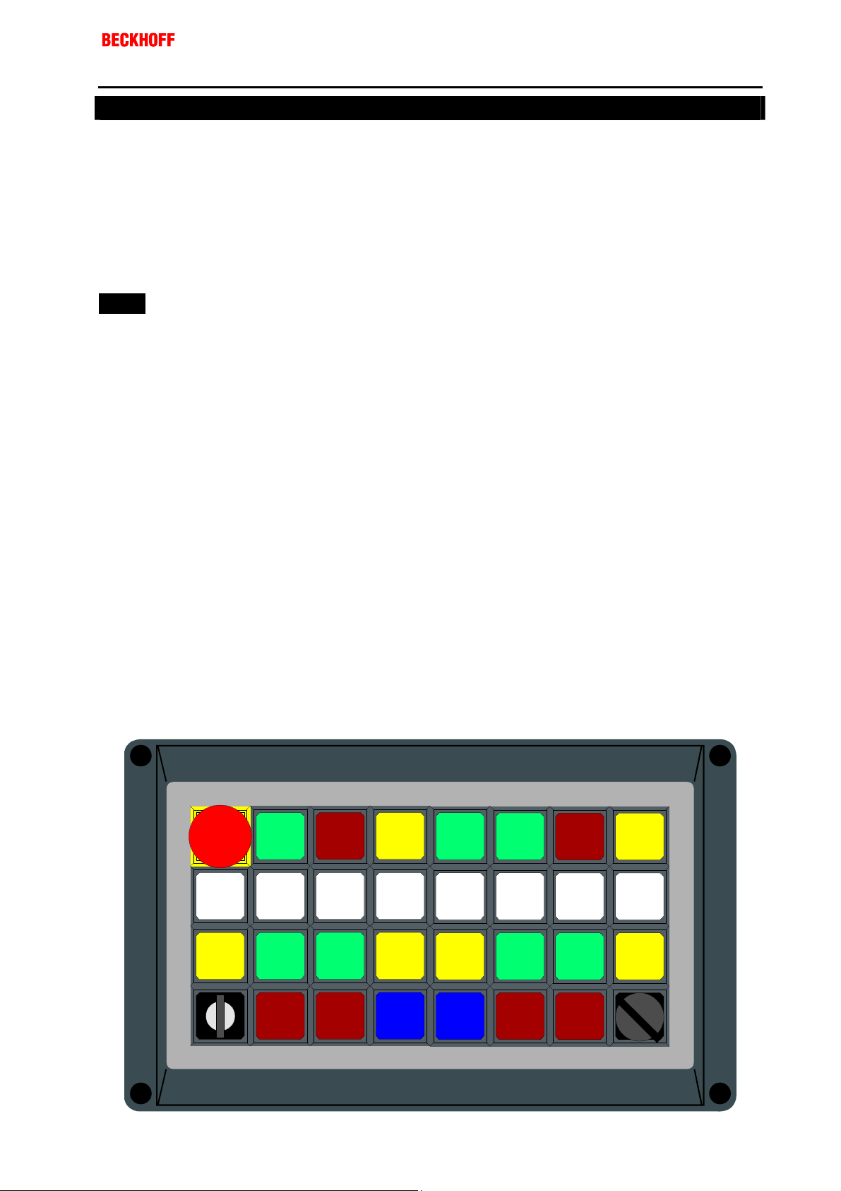
The M6330 control unit is fitted with a choice of switching elements. Switch
positions are read via the II/O Lightbus, and indicator lights are driven by
the central controller.
Some of the switching elements are wired to screw terminals, to control, for
instance, emergency off switches or a main contactor.
- Stackable 8 * 4 keypad to be fitted with a choice
of keyswitches, indicator lights, emergency off
switches etc.
- 32 electromechanical illuminated switches, wired
to the II/O Lightbus as make contact inputs and
indicator light outputs, of which 8 are additionally
wired as changeover contacts to screw terminals
- Keys and switching elements: Manufactured by
Schlegel
- In aluminium housing (M6330)
or as built-in panel (M6331)
- optionally with 32 keys (M6330-000),
with 31 keys + emergency off (M6330-001),
without keys (M6330-010),
or customer-specific (M6330-030)
Page 2
INDUSTRIE
INDUSTRIE ELEKTRONIK
INDUSTRIEINDUSTRIE
ELEKTRONIK Eiserstraße 5 / D-33415 Verl / Phone 05246/963-0 / Fax 05246/963-149
ELEKTRONIK ELEKTRONIK
M6330 Control Unit Page 2
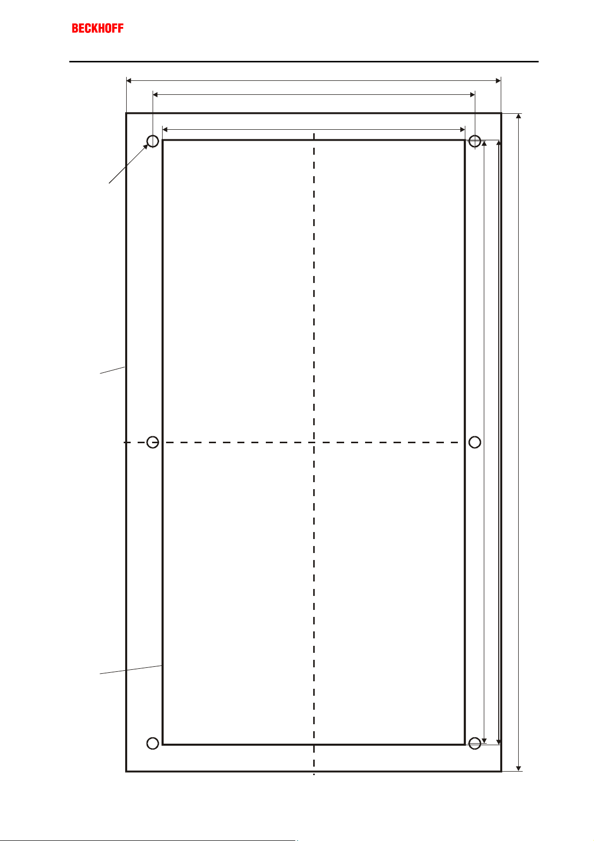
134.0
115.0
108.0
M4 thread
or throughhole
Outside
contour of
the key
module
Cut-out in
carrier
plate
215.0
216.0
243.0
Assembly hole for the M6331 built-in panel
Page 3
INDUSTRIE
INDUSTRIE ELEKTRONIK
INDUSTRIEINDUSTRIE
ELEKTRONIK Eiserstraße 5 / D-33415 Verl / Phone 05246/963-0 / Fax 05246/963-149
ELEKTRONIK ELEKTRONIK
M6330 Control Unit Page 3
Mechanical Features
- External dimensions of aluminium diecast housing: 240 * 160 * 117 mm, type ROLEC
- Built-in panel: External dimensions of built-in plate: 243 * 134 mm
Hole required: 216 * 108 mm, page 2
- If the rear of the device will no longer be accessible after assembly, making it mechanically necessary to
plug in the connecting strip before the built-in panel is fitted, the hole needs to be 226 * 108 mm large.
An appropriate drawing can be requested.
- Mounting depth: 78 mm under the front panel
- Key arrangement: see page 1
- Protection type: for version mounted in housing, IP65 on all sides
for built-in panel, IP65 to the front
- Fitting to customer-specific housings is a possible option
Fittings
- All actuators in the SCHLEGEL OKTRON range that can be combined with normal contact makers can be
used
- Key cap colours optionally white, green, yellow, blue or red
- Marking with standard symbols using ready-made labelling inserts or blank inserts for special signs
General Electrical Properties
- 32 electro-mechanical keys from the SCHLEGEL OKTRON series, illuminated, pre-wired as make contact.
The upper 8 keys are optionally connected to a terminal strip for 24 V wiring. They are pre-wired as
changeover contacts. One of these keys is wired specially (to a single-terminal connection) for an
emergency off function
In 24 V applications the 8 switches are electrically galvanically isolated from the electronics
- Power supply 24 V DC, 400 mA + 30 mA per lamp
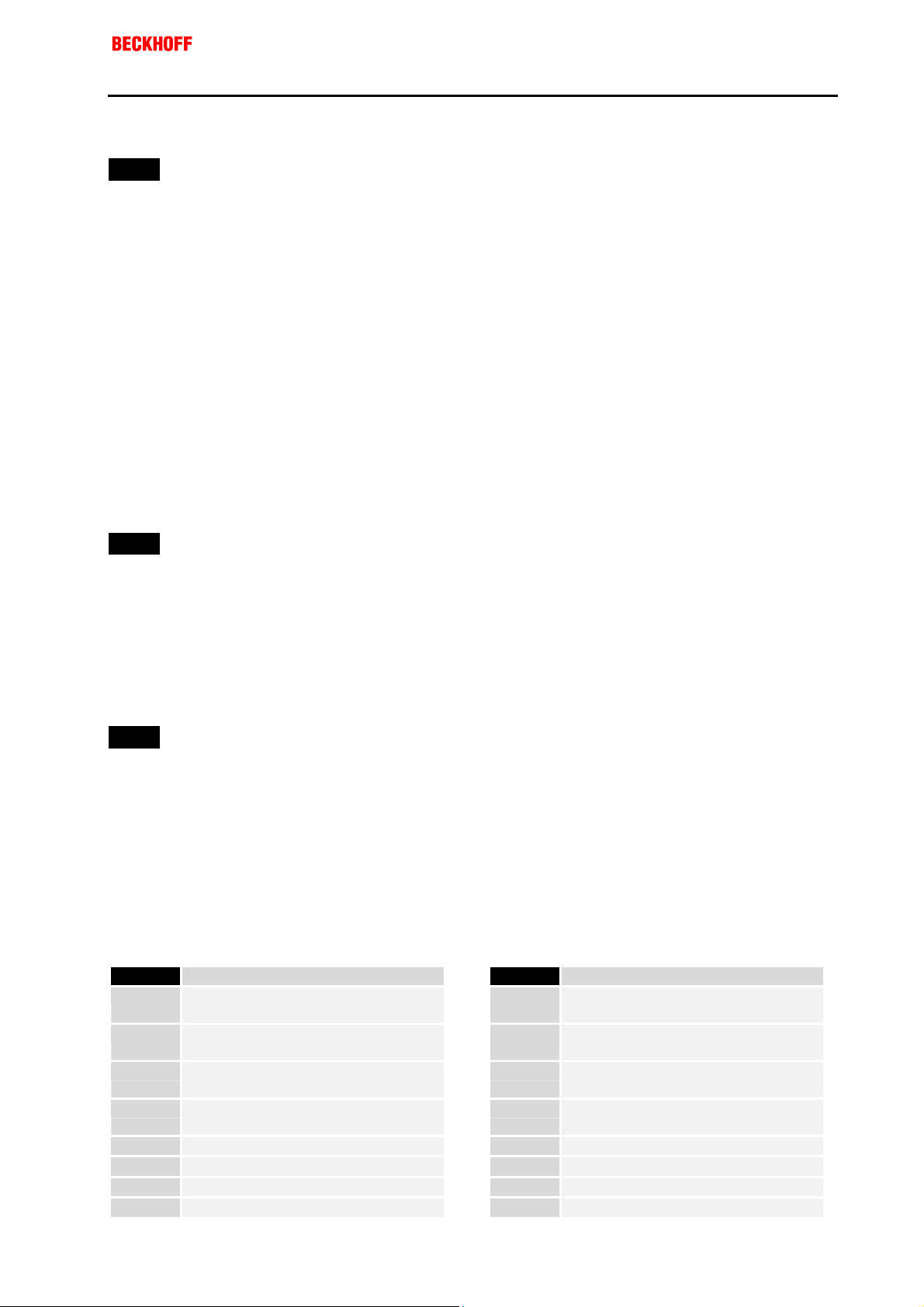
Terminal no. Function Terminal no. Function
13 from emergency off switch /
A/B 1
switch B 100
14 from emergency off switch /
A/B 2
switch B 100
21 from emergency off switch /
A/B 3
switch B 100
22 from emergency off switch /
A/B 4
switch B 100
A/B 5 13/21 from switch A / B 101 A/B 13 22 from switch A / B 103
A/B 6 14 from switch A / B 101 A/B 14 0 V
A/B 7 22 from switch A / B 101 A/B 15 +24 V power supply
A/B 8 13/21 from switch A / B 102
A/B 9 14 from switch A / B 102
A/B 10 22 from switch A / B 102
A/B 11 13/21 from switch A / B 103
A/B 12 14 from switch A / B 103
Page 4

INDUSTRIE
INDUSTRIE ELEKTRONIK
INDUSTRIEINDUSTRIE
ELEKTRONIK Eiserstraße 5 / D-33415 Verl / Phone 05246/963-0 / Fax 05246/963-149
ELEKTRONIK ELEKTRONIK
M6330 Control Unit Page 4
Wiring Instructions
- The upper row of keys is configured for 5 V operation as standard. Operation with 24 V is possible
without modification. It should be noted here that the working voltage is brought to contact 13/21 of the
changeover switch, and the related load is connected to the make contact 14 and/or to the break contact
22.
- All 4 contacts on the optional EMERGENCY OFF switch are accessible at the terminal strip. If, for a special
application, the 5 V supply at contact 13.0 is not desired, it can be disconnected by opening a soldering
jumper. The position of the soldering jumper on the board can be seen in the diagram on page 3.
The make contact 14.0 remains connected to input D0.0, while break contacts 21-22 are available and
without voltage.
II/O Lightbus Telegram Assignments
The two modules are to be connected in series. The output from module A is usually connected to the input
of module B. This means that module A is to be entered first in the S1000 software II/O setup.
The tables on the following page apply to both of the modules.
M6330 D0 D1 D2 D3
Inputs for keys 100 - 103 and 200 - 211 Outputs for lamps 100 - 103 and 200 - 211
Signal Function Signal Function
D0.0 Input key 100 D2.0 Output lamp 100
D0.1 Input key 101 D2.1 Output lamp 101
D0.2 Input key 102 D2.2 Output lamp 102
D0.3 Input key 103 D2.3 Output lamp 103
D0.4 Input key 200 D2.4 Output lamp 200
D0.5 Input key 201 D2.5 Output lamp 201
D0.6 Input key 202 D2.6 Output lamp 202
D0.7 Input key 203 D2.7 Output lamp 203
D1.0 Input key 204 D3.0 Output lamp 204
D1.1 Input key 205 D3.1 Output lamp 205
D1.2 Input key 206 D3.2 Output lamp 206
D1.3 Input key 207 D3.3 Output lamp 207
D1.4 Input key 208 D3.4 Output lamp 208
D1.5 Input key 209 D3.5 Output lamp 209
D1.6 Input key 210 D3.6 Output lamp 210
D1.7 Input key 211 D3.7 Output lamp 211
Page 5

INDUSTRIE
INDUSTRIE ELEKTRONIK
INDUSTRIEINDUSTRIE
ELEKTRONIK Eiserstraße 5 / D-33415 Verl / Phone 05246/963-0 / Fax 05246/963-149
ELEKTRONIK ELEKTRONIK
M6330 Control Unit Page 5
II/O Lightbus
BECKHOFF M6321
input
II/O Lightbus
XILINX
®
output
XILINX
®
Soldering jumper for
EMERGENCY OFF key
Terminal st rip A
Termi nal st rip B
 Loading...